US8343112B2 - Disinfecting caps having an extendable feature and related systems and methods - Google Patents
Disinfecting caps having an extendable feature and related systems and methodsDownload PDFInfo
- Publication number
- US8343112B2 US8343112B2US12/956,704US95670410AUS8343112B2US 8343112 B2US8343112 B2US 8343112B2US 95670410 AUS95670410 AUS 95670410AUS 8343112 B2US8343112 B2US 8343112B2
- Authority
- US
- United States
- Prior art keywords
- cap
- inner housing
- housing
- outer housing
- male
- Prior art date
- Legal status (The legal status is an assumption and is not a legal conclusion. Google has not performed a legal analysis and makes no representation as to the accuracy of the status listed.)
- Active, expires
Links
Images


Classifications
- A—HUMAN NECESSITIES
- A61—MEDICAL OR VETERINARY SCIENCE; HYGIENE
- A61M—DEVICES FOR INTRODUCING MEDIA INTO, OR ONTO, THE BODY; DEVICES FOR TRANSDUCING BODY MEDIA OR FOR TAKING MEDIA FROM THE BODY; DEVICES FOR PRODUCING OR ENDING SLEEP OR STUPOR
- A61M39/00—Tubes, tube connectors, tube couplings, valves, access sites or the like, specially adapted for medical use
- A61M39/10—Tube connectors; Tube couplings
- A61M39/16—Tube connectors; Tube couplings having provision for disinfection or sterilisation
- A61M39/165—Shrouds or protectors for aseptically enclosing the connector
- A—HUMAN NECESSITIES
- A61—MEDICAL OR VETERINARY SCIENCE; HYGIENE
- A61L—METHODS OR APPARATUS FOR STERILISING MATERIALS OR OBJECTS IN GENERAL; DISINFECTION, STERILISATION OR DEODORISATION OF AIR; CHEMICAL ASPECTS OF BANDAGES, DRESSINGS, ABSORBENT PADS OR SURGICAL ARTICLES; MATERIALS FOR BANDAGES, DRESSINGS, ABSORBENT PADS OR SURGICAL ARTICLES
- A61L2/00—Methods or apparatus for disinfecting or sterilising materials or objects other than foodstuffs or contact lenses; Accessories therefor
- A61L2/16—Methods or apparatus for disinfecting or sterilising materials or objects other than foodstuffs or contact lenses; Accessories therefor using chemical substances
- A61L2/18—Liquid substances or solutions comprising solids or dissolved gases
- A—HUMAN NECESSITIES
- A61—MEDICAL OR VETERINARY SCIENCE; HYGIENE
- A61M—DEVICES FOR INTRODUCING MEDIA INTO, OR ONTO, THE BODY; DEVICES FOR TRANSDUCING BODY MEDIA OR FOR TAKING MEDIA FROM THE BODY; DEVICES FOR PRODUCING OR ENDING SLEEP OR STUPOR
- A61M39/00—Tubes, tube connectors, tube couplings, valves, access sites or the like, specially adapted for medical use
- A61M39/10—Tube connectors; Tube couplings
- A61M39/16—Tube connectors; Tube couplings having provision for disinfection or sterilisation
- A61M39/162—Tube connectors; Tube couplings having provision for disinfection or sterilisation with antiseptic agent incorporated within the connector
- A—HUMAN NECESSITIES
- A61—MEDICAL OR VETERINARY SCIENCE; HYGIENE
- A61M—DEVICES FOR INTRODUCING MEDIA INTO, OR ONTO, THE BODY; DEVICES FOR TRANSDUCING BODY MEDIA OR FOR TAKING MEDIA FROM THE BODY; DEVICES FOR PRODUCING OR ENDING SLEEP OR STUPOR
- A61M39/00—Tubes, tube connectors, tube couplings, valves, access sites or the like, specially adapted for medical use
- A61M39/20—Closure caps or plugs for connectors or open ends of tubes
- A—HUMAN NECESSITIES
- A61—MEDICAL OR VETERINARY SCIENCE; HYGIENE
- A61M—DEVICES FOR INTRODUCING MEDIA INTO, OR ONTO, THE BODY; DEVICES FOR TRANSDUCING BODY MEDIA OR FOR TAKING MEDIA FROM THE BODY; DEVICES FOR PRODUCING OR ENDING SLEEP OR STUPOR
- A61M2207/00—Methods of manufacture, assembly or production
- B—PERFORMING OPERATIONS; TRANSPORTING
- B65—CONVEYING; PACKING; STORING; HANDLING THIN OR FILAMENTARY MATERIAL
- B65D—CONTAINERS FOR STORAGE OR TRANSPORT OF ARTICLES OR MATERIALS, e.g. BAGS, BARRELS, BOTTLES, BOXES, CANS, CARTONS, CRATES, DRUMS, JARS, TANKS, HOPPERS, FORWARDING CONTAINERS; ACCESSORIES, CLOSURES, OR FITTINGS THEREFOR; PACKAGING ELEMENTS; PACKAGES
- B65D41/00—Caps, e.g. crown caps or crown seals, i.e. members having parts arranged for engagement with the external periphery of a neck or wall defining a pouring opening or discharge aperture; Protective cap-like covers for closure members, e.g. decorative covers of metal foil or paper
- B65D41/02—Caps or cap-like covers without lines of weakness, tearing strips, tags, or like opening or removal devices
- Y—GENERAL TAGGING OF NEW TECHNOLOGICAL DEVELOPMENTS; GENERAL TAGGING OF CROSS-SECTIONAL TECHNOLOGIES SPANNING OVER SEVERAL SECTIONS OF THE IPC; TECHNICAL SUBJECTS COVERED BY FORMER USPC CROSS-REFERENCE ART COLLECTIONS [XRACs] AND DIGESTS
- Y10—TECHNICAL SUBJECTS COVERED BY FORMER USPC
- Y10S—TECHNICAL SUBJECTS COVERED BY FORMER USPC CROSS-REFERENCE ART COLLECTIONS [XRACs] AND DIGESTS
- Y10S604/00—Surgery
- Y10S604/905—Aseptic connectors or couplings, e.g. frangible, piercable
Definitions
- the present disclosuregenerally relates to caps for medical connectors and more specifically relates to caps that can be used to protect the cleanliness of unconnected medical connectors, such as connectors that may be used for fluid flow or for fluid delivery systems. Some embodiments are directed to caps for medical connectors that include elongated male portions.
- Bloodstream infectionssuch as may be caused by microorganisms that enter patients via intravascular catheters, are a significant cause of illness and excess medical costs. A substantial number of such infections occur in U.S. intensive care units annually. Additionally, a significant fraction of these infections result in death.
- Impregnating catheters with various antimicrobial agentsis one approach for reducing these infections. Impregnated catheters, however, provide less than satisfactory results. Additionally, some microbes have developed resistance to the various antimicrobial agents used in the catheters. Other systems and approaches have also been developed, but these likewise suffer from a variety of limitations and drawbacks.
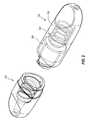
- FIG. 1is a perspective view of an embodiment of an assembly that includes an embodiment of a male cap and an embodiment of a female cap that are coupled with each other in a closed or pre-use configuration;
- FIG. 2is a perspective view of the system of FIG. 1 in an open configuration in which the male and female caps are separated from each other;
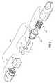
- FIG. 3is an exploded perspective view of the system of FIG. 1 ;
- FIG. 4Ais a top plan view of an embodiment of a housing portion of a female cap that is compatible with the assembly of FIG. 1 ;
- FIG. 4Bis a side elevation view of the housing portion of the female cap of FIG. 4A ;
- FIG. 4Cis a front elevation view of the housing portion of the female cap of FIG. 4A ;
- FIG. 5Ais a top plan view of an embodiment of a housing portion of a male cap that is compatible with the assembly of FIG. 1 ;
- FIG. 5Bis a side elevation view of the housing portion of the male cap of FIG. 5A ;
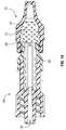
- FIG. 5Cis a cutaway perspective view of the housing portion of the male cap of FIG. 5A ;
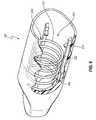
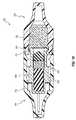
- FIG. 6is a cutaway perspective view of the housing portion of the male cap, as shown in FIG. 5C , with an embodiment of a biasing element disposed therein;
- FIG. 7is a cutaway perspective view of the housing portion of the male cap, as shown in FIG. 5C , with both an embodiment of a biasing element and an embodiment of a carriage disposed therein;
- FIG. 8is a rear perspective view of the carriage that is also shown in FIG. 7 ;
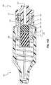
- FIG. 9is a cross-sectional view of the assembly of FIG. 1 in the pre-use state
- FIG. 10Ais a top plan view of the assembly of FIG. 1 in the pre-use state with an arrow indicating rotation of the female cap relative to the male cap to assist in transitioning the assembly to the open state;
- FIG. 10Bis another top plan view of the assembly of FIG. 1 showing the female cap having been rotated relative to the male cap so as to assist in translating the female cap away from the male cap;
- FIGS. 11A-11Dare cross-sectional views that depict various stages of an illustrative method for coupling a medical connector with the male cap of FIG. 1 ;
- FIG. 12is a cross-sectional view of the female cap of FIG. 1 coupled with an embodiment of a needleless injection site;
- FIG. 13is a cross-sectional view of the female cap of FIG. 1 coupled with another embodiment of a needleless injection site;
- FIG. 14is a cross-sectional view of the female cap of FIG. 1 coupled with another embodiment of a needleless injection site;
- FIG. 15is a cross-sectional view of another embodiment of an assembly that includes an embodiment of a male cap and an embodiment of a female cap that are coupled with each other in a closed or pre-use configuration;
- FIG. 16is an expanded view of the cross-sectional view shown in FIG. 15 ;
- FIG. 17is a cutaway perspective view of an embodiment of a housing portion of another embodiment of a male cap
- FIG. 18is a cross-sectional view of another embodiment of an assembly that includes an embodiment of a male cap coupled with an embodiment of a female cap;
- FIG. 19is a cross-sectional view of another embodiment of an assembly that includes an embodiment of a male cap coupled with an embodiment of a female cap;
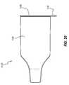
- FIG. 20is a side elevation view of another embodiment of a male cap.
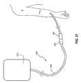
- FIG. 21is a perspective view of a fluid line that includes a coupled set of connectors that are amenable to being coupled with male and female caps, respectively.
- capsthat can be used to protect and/or disinfect medical connectors. Systems and methods related to such caps are also disclosed. The caps, systems, and methods can reduce the threat of microorganisms entering the bloodstream of a patient via fluid flow or fluid delivery systems, such as, for example, needleless injection sites and/or fluid transfer devices having an elongated male portion or male protrusion, such as, for example, a male luer.
- a capis configured to couple with and disinfect a medical connector having a male protrusion.
- the capcan include an antiseptic, and can be configured to create a seal with the male protrusion so as prevent antiseptic from entering a lumen of the male protrusion.
- the antisepticmay be contained within a pad prior to the coupling of the cap to the medical connector, and the act of coupling the cap to the medical connector can force at least a portion of the antiseptic from the pad and into contact with the male protrusion.
- the male capcan be coupled with a female cap to form an assembly.
- the male capcan include a translatable portion that is retained in a retracted position when the assembly is in a pre-use state. Separation of the male and female caps can result in translation of the translatable portion to an extended position that is more readily accessible by a medical connector.
- FIG. 21illustrates an example of medical connectors 300 , 360 for which caps disclosed herein may be used.
- Any suitable variety of medical connectors 300 , 360is possible, such as, for example, luer lock connectors.
- the connectors 300 , 360are associated with a fluid pathway 1200 , such as a fluid line 1205 of any suitable variety, which may be coupled with an IV bag 1210 or other suitable fluid delivery system.
- the fluid pathway 1200can be used to intermittently administer medications to a patient P.
- the connector 360 of the fluid pathway 1200which communicates fluids with a patient's blood stream, may be selectively disconnected from the connector 300 .
- One or more of the connectors 300 , 360may be connected to other connectors (not shown), such as a connector associated with a central line.
- the medical connectors 300 , 360may be connected and disconnected at various times, and may remain disconnected for several minutes or hours.
- Medical connector caps disclosed hereincan be used to cover and protect the various medical connectors 300 , 360 while the connectors are separated from one another.
- each separated connectorcan benefit from being covered by a cap. Therefore, in some cases, it can be advantageous to have a single connector set or assembly that includes both a male cap and a female cap that can be used to provide protection for both ends of a separated connection.
- a capcan include an antiseptic for disinfecting a medical connector. In some cases, it can be advantageous for the cap to form a seal with a portion of the medical connector to thereby prevent the antiseptic from exiting the cap into the fluid pathway.
- a male capincludes a translatable portion that is retained in a retracted position when the cap assembly is in a pre-use state. Separation of the male and female caps can result in translation of the translatable portion to an extended position that is more readily accessible by a medical connector.
- FIGS. 1-3illustrate an embodiment of a set or assembly 100 that includes an embodiment of a female cap 102 and an embodiment of a male cap 104 , each of which can be used to cover a separated connector 360 , 300 , respectively.
- the assembly 100can be provided in a pre-use, assembled, or closed state in which the female and male caps 102 , 104 are coupled with each other, as shown in FIG. 1 .
- the caps 102 , 104when the caps 102 , 104 are coupled with each other, they may form a fluid-tight seal, which can prevent antiseptic from evaporating from an interior of the assembly 100 to an exterior thereof.
- the female and male caps 102 , 104can be coupled with each other via a sealing mechanism 189 .
- the sealing mechanism 189comprises a sealing sleeve 191 , which is fixedly connected to (e.g., integrally formed with) the male cap 104 .
- the terms “coupled” and variants thereofare used in their ordinary sense and include arrangements such as that illustrated in FIG. 1 , in which the caps 102 , 104 directly engage one another when the assembly 100 is in the assembled or pre-use state.
- the female and male caps 102 , 104can be separated from each other. It may be said that the assembly 100 is in an open or operational state when it is in such an arrangement. In the illustrated embodiment, all components of the assembly 100 are contained in or otherwise embodied by one of the female and male caps 102 , 104 . Accordingly, in some embodiments, the assembly 100 can be devoid of pieces or parts that are readily separable from either of the female and male caps 102 , 104 during or after a transition of the assembly 100 from the closed to the open state.
- the female and male caps 102 , 104each can comprise separate, self-contained, or individual assemblies that may be directly joined to each other, thereby resulting in the composite assembly 100 it its closed state (shown in FIG. 1 ), and that may be separated from each other, thereby resulting in the disassembled assembly 100 in its open state (shown in FIG. 2 ).
- a lack of separate, additional parts when the female and male caps 102 , 104 are disconnected from each othercan have a variety of advantages. For example, such arrangements can, among other things, provide for a less cluttered work space or environment when one or more of the caps 102 , 104 are in use.
- the male cap 104can include an outer housing 150 , which can receive a translating or telescoping member, shuttle, or carriage 200 .
- the carriage 200can be configured to transition between a retracted (e.g., distal) position and an extended (e.g., proximal) position. In FIG. 2 , the carriage 200 is in the extended position, whereas it is in the retracted position in FIG. 9 , as discussed further below.
- the male cap 104can include a biasing member 202 , which can be configured to urge or bias the carriage 104 proximally toward the extended position.
- proximal and distalwhen used herein relative to a cap, or components thereof, are used relative to the coupling of the cap with a medical device, such that the medical device is inserted into a proximal end of the cap, or component thereof and advanced toward a distal end of the cap or component. Accordingly, in the illustrated embodiment, the proximal ends of the caps 102 , 104 are directed toward each other and the distal ends of the caps 102 , 104 are directed away from each other when the assembly 100 is in the pre-use configuration (see FIG. 1 ).
- FIG. 3is an exploded view of the assembly 100 .
- the female cap 102can include a housing 110 into which an antiseptic reservoir or pad 132 is received.
- the male cap 104can include a carriage 200 , which can be configured to receive a resilient support 177 , an antiseptic reservoir or pad 170 , and a sealing member 190 .
- the resilient support 177 and the pad 170may be considered as a multi-part biasing member 176 that is configured to urge the sealing member 190 toward a proximal end of the carriage 200 .
- the housing 150 of the cap 104can be configured to receive the biasing member 202 and the carriage 200 .
- the carriage 200comprises a movable, translatable, or inner housing 210
- the biasing member 202comprises a coil spring 212 .
- the coil spring 212can be configured to urge the inner housing 210 in the proximal direction, or toward a proximal end of the shell or outer housing 150 .
- the housing 110 of the female cap 102can extend between a closed distal end and an open proximal end.
- the closed distal enddoes not permit any fluid flow therethrough and serves as a barrier between an interior of the housing 110 and an exterior environment.
- the open proximal end of the housing 110is configured to receive at least a portion of a medical connector therein, as further discussed below with respect to FIGS. 12-14 .
- the housing 110can include a sidewall 112 , which defines the open proximal end, and a base wall 113 , which defines at least a portion of the closed distal end.
- the housing 110can include a body region 136 near a proximal end thereof, which is substantially cylindrically shaped in the illustrated embodiment.
- a handle 137can extend from the body region 136 so as to be positioned at the distal end of the cap 102 .
- the handle 137can comprise any suitable gripping features 103 , which, in the illustrated embodiment, comprise opposing gripping regions or grasping platforms 138 that are configured to provide a convenient surface against which a user can press so as to hold and/or twist the cap 102 .
- the illustrated grasping platforms 138are mirrored about a longitudinal plane LP that extends along a central longitudinal axis A (shown in FIG. 4A ) of the housing 110 .
- Each grasping platform 138angles radially inwardly from the body region 136 toward the longitudinal plane LP, in a proximal-to-distal direction.
- the grasping platforms 138are more steeply angled at their proximal ends than they are at their distal ends.
- the angled platforms 138and particularly the steeply angled portions thereof, provide convenient surfaces to which forces may be applied in a distal-to-proximal direction.
- the platforms 138define two substantially planar regions that are smoothly joined to each other at a rounded transition.
- the platforms 138can define a contour that is substantially complementary to fingertips that are pointed in the proximal direction.
- the illustrated grasping platforms 138also taper inwardly toward the central longitudinal axis A of the housing 110 in a proximal-to-distal direction.
- the platforms 138are substantially ovoid.
- the platforms 138are sized and shaped to be held between the fingertips of a thumb and another finger (e.g., the index finger) of a user, although other grasping configurations may also be efficiently employed with the illustrated arrangement.
- the platforms 138provide convenient surfaces to which torque may be applied so as to rotate the cap 102 about the longitudinal axis A.
- the cap 102can include a lip, rim, or flange 115 that extends radially inwardly at a proximal end of the body region 136 .
- the flange 115can define one or more recesses 116 , which can be complementary to features of the male cap 104 so as to define at least a portion of a separation assisting cam, as discussed further below.
- the flange 115also can contact an edge of the sleeve 191 portion of the male cap 104 to ensure the desired insertion depth of the cap 102 within the sleeve 191 .
- each recess 116can be at least partially defined by a pair of faces 116 a , 116 b of the flange 115 that are angled in opposite directions.
- the anglescan be any suitable non-zero, non-180-degree angles relative to a transverse cross-sectional plane TP that passes perpendicularly through the a central axis A of the housing 110 .
- the faces 116 acan define an angle ⁇ relative to the transverse plane TP
- the faces 116 bcan define an angle ⁇ relative to the transverse plane TP.
- the angles ⁇ , ⁇are the same, although other arrangements are possible (as discussed further below).
- the faces 116 a , 116 bcan be substantially planar over at least a portion thereof, and can be configured to complementarily contact faces of the sleeve 191 . Additional discussion of the faces 116 a , 116 b is provided below with respect to FIGS. 10A-10B .
- the housing 110defines an external surface 118 and an internal surface 119 , each of which extends away from the flange 115 .
- the internal surface 119 of the cap 102can include an outwardly directed surface of the sidewall 112 , a proximal end 124 of the sidewall 112 , and an inwardly directed surface of the sidewall 112 (see FIGS. 4C and 9 ).
- the outwardly directed portion of the internal surface 119can define a connection interface 140 that is configured to interact with or engage a connection interface 195 of the sleeve 191 (see FIG. 5C ) so as to connect the cap 102 to the sleeve 191 .
- connection interfaces 140 , 195couple with each other via a friction-fit engagement.
- an inner diameter of the connection interface 195 of the sleeve 191can be slightly smaller than an outer diameter of the connection interface 140 of the cap 102 .
- the friction fitcan be sufficiently strong to provide a fluid-tight seal between the cap 102 and the sleeve 191 , yet can allow the cap 102 to be removed from the sleeve 191 via manipulation by a user (e.g., without the use of ancillary tools).
- the fluid-tight sealcan prevent evaporative loss of antiseptic from an interior of the assembly 100 when it is in the pre-use configuration and/or can maintain the sterility of the internal portions of the assembly 100 .
- connection interfaces 140 , 195can include snap-fit devices, threads, and/or any other suitable attachment features.
- a proximal portion of the connection interface 140includes a chamfer 120 , which can assist in centering the cap 102 relative to the sleeve 191 when connecting the cap 102 to the sleeve 191 .
- the proximal end 124 of the housing 110(which is also a proximal end of the internal surface 119 , or more generally, of the sidewall 112 ), can define a seal inhibitor 125 , which can include one or more contact regions 126 and one or more venting regions 127 .
- the seal inhibitor 125includes two contact regions 126 that are diametrically opposite from each other, and also includes two venting regions 127 that are diametrically opposite from each other and are angularly spaced from the contact regions.
- Other configurations of the seal inhibitor 125are also possible, such as, for example, the seal inhibitors discussed in U.S. patent application Ser. No.
- the inwardly directed portion of the internal surface 119 of the sidewall 112can define a disinfection chamber 122 , which can include a connection interface 130 .
- a connection interface 130Any suitable connection system may be used for the connection interface 130 .
- the connection interfaceincludes threads 131 .
- the connection interface 130can be configured to attach the cap 102 to a medical connector in a secure yet selectively removable manner.
- the cap 102can be connected in any suitable manner with any suitable medical connector.
- connection interface 130may include latches or prongs that are configured to snap over an outwardly extending rib of a connector, or may include one or more outwardly extending ribs over which one or more latches or prongs of the medical connector may snap.
- Other interfacing arrangementsare also possible, which may include friction-fit, snap-fit, or other suitable mechanisms.
- a proximal portion of the disinfection chamber 122can be larger than a distal extension 123 of the chamber.
- the disinfection chamber 122defines three substantially frustoconical regions.
- the proximal regionhas a slightly tapered outer boundary that decreases in cross-sectional area in the distal direction;
- the intermediate regionhas a more pronounced tapered outer boundary that more rapidly decreases in cross-sectional area in the distal direction;
- the distal region or distal extension 123has a slightly tapered outer boundary that decreases in cross-sectional area in the distal direction at about the same rate as the proximal region.
- the intermediate and distal regionscorrespond with the proximal and distal regions, respectively, of the grasping platforms.
- the constricted intermediate region of the disinfection chamber 122can provide a reactive force to a distal end of the pad 132 when the cap 102 is secured to a medical connector.
- the reactive forcecan be sufficient to prevent the pad 132 from being forced into the distal extension 123 .
- the threads 131also provide resistive forces.
- Axial compression of the pad 132 as the cap 102 is coupled to a medical connectorcan swab the connector and deliver antiseptic 133 from the pad 132 into contact with the medical connector, as further discussed below.
- the pad 132may be resiliently deformable so as to regain a pre-use shape after a medical connector is decoupled from the cap 102 .
- the pad 132may instead be plastically deformable.
- the pad 132can be configured to retain an antiseptic 133 .
- the pad 132can comprise any suitable sponge-like material, such as an elastomeric foam, any open-cell foam, felt, or non-woven fiber matrix, and can be configured to conform to the contours of a portion of a medical connector that is introduced into the disinfection chamber 122 (e.g., uneven surfaces of an end of a needleless injection site; see also FIGS. 12-14 and the associated written description).
- the pad 132can also comprise any closed-cell foam, as well as a solid elastomeric material, such as silicone or the like.
- the pad 132can have a series or network of openings or spaces therein that can retain the antiseptic 133 when the pad 132 is in an expanded state.
- the antiseptic 133can be received within, occupy, fill (or partially fill), wet, soak, or saturate at least a fraction of the pad 132 , or stated otherwise, can fill the pad 132 to a given concentration level. Compression of the pad 132 can cause antiseptic 133 to egress from the pad 132 so as to contact the medical connector. Resilient expansion of the foam upon removal of a compressive force can allow the pad 132 to soak up or absorb at least some of the antiseptic 133 that had previously been forced from the pad 132 .
- the antiseptic 133can comprise any liquid antiseptic, such as, for example, alcohol (e.g., isopropyl alcohol) at various concentrations (e.g., ranging from 50-90%), ethanol at various concentrations (e.g., ranging from 50-95%), and combinations of any alcohols with any antiseptics, or a dry material, such as chlorhexidine, ethylenediaminetetraacetic acid (EDTA), lodaphors, or any suitable combination thereof.
- alcohole.g., isopropyl alcohol
- ethanole.g., ranging from 50-95%
- combinations of any alcohols with any antisepticse.g., ranging from 50-95%
- a dry materialsuch as chlorhexidine, ethylenediaminetetraacetic acid (EDTA), lodaphors, or any suitable combination thereof.
- EDTAethylenediaminetetraacetic acid
- the pad 132when the assembly 100 is in the pre-use condition, the pad 132 is in a relaxed, expanded, or uncompressed state in a longitudinal direction. It is noted that the pad 132 may be uncompressed in one or more dimensions, yet compressed in one or more other dimensions, when the assembly 100 is in the pre-use state. For example, the pad 132 can be expanded or in a relaxed state in a longitudinal direction, yet compressed radially inwardly via the sidewall 112 , when the assembly 100 is in the pre-use state.
- the pad 132is substantially square in cross-section along its full longitudinal length when the pad 132 is in a relaxed orientation (see FIG. 3 ). Such an arrangement can facilitate and/or reduce material costs associated with the manufacture of the pad 132 . At least a portion of the pad 132 (e.g., the corners thereof) may be compressed radially when the pad 132 is positioned within the housing 112 . Other rectangular cross-sections are also possible for the pad 132 , and in other or further embodiments, the pad 132 may define a rectangular cross-section along only a portion of the longitudinal length thereof. In other embodiments, at least a portion of the pad 132 may define a round cross-section, such as a circular, elliptical, or other ovoid shape. For example, the pad 132 can be cylindrical so as to have a circular cross-section. The pad 132 may define any other suitable shape, and may or may not be radially compressed when the assembly 100 is in the pre-use state.
- the housing 150 of the male cap 104can extend between a closed distal end and an open proximal end.
- the closed distal enddoes not permit any fluid flow therethrough and serves as a barrier between an interior of the housing 150 and an exterior environment.
- the open proximal end of the housing 150is configured to receive at least a portion of a medical connector therein and/or to permit passage of at least a portion of the carriage 200 therethrough.
- a shape and/or configuration of the distal end of the housing 150can be similar or identical to the distal end of the housing 110 of the female cap 102 , which is discussed above.
- the housing 150includes a body region 136 and a handle 137 with grasping platforms 138 , which when viewed exteriorly, are identical to the identically numbered features of the cap 102 .
- distal ends of an exterior thereofcan be symmetrical about three mutually perpendicular planes. Other arrangements are also possible.
- the housing 150can include one or more protrusions 197 that are configured to mate or cooperate with the recesses 116 of the female cap 102 .
- each pair of coupled protrusions 197 and recesses 116 , or portions thereof,can operate as a separation assist 107 , as further discussed below with respect to FIGS. 10A and 10B .
- the housing 150can include a lip, rim, or flange 198 that extends radially inwardly at a proximal end of the sleeve 191 .
- the housing 150can define an external surface 165 and an internal surface 166 , each of which extends away from the flange 198 .
- the internal surface 166 of the cap 104can define the connection interface 195 discussed above.
- the flange 198can contact the flange 115 of the female cap 102 , which can ensure the desired insertion depth of the cap 102 within the sleeve 191 . At least a portion of the flange 198 can be shaped complementarily to the flange 115 of the cap 102 . With reference to FIGS. 5A and 5B , the flange 198 can define a pair of faces 199 a , 199 b that are angled in opposite directions.
- the housing 150can define a receptacle or cavity 220 within which the carriage 200 may move between the retracted and extended positions.
- the housing 150can further define one or more movement constraining members 230 , which may extend inwardly from (e.g., project inwardly) or extend outwardly from (e.g., be recessed relative to) the interior surface 166 of the housing 150 .
- the housing 150can include one or more, two or more, three or more, or four or more movement constraining members 230 .
- the illustrated embodimentincludes four movement constraining members 230 (only two of which are shown in FIG. 5C ) that are angularly spaced from each other at approximately 90 degree intervals. Other suitable arrangements are also possible.
- each constraining member 230comprises an inwardly projecting track, protrusion, or spline 232 .
- Each illustrated spline 232includes a proximal stopping member or stop 233 , which can comprise a lock, latch, detent, or any other suitable stopping mechanism.
- each proximal stop 233is substantially wedge shaped and includes a distally angled entry face 234 , which can facilitate an overriding force or snap fit during manufacturing, and a transversely extending locking face 235 .
- the splines 232also can include transversely extending distal stopping faces 237 , 238 .
- the splines 232are elongated structures (e.g., ribs) that extend substantially parallel to each other.
- the splines 232are elongated in the longitudinal direction, and each may be substantially parallel to a longitudinal axis defined by the housing 150 .
- the splines 232can have a helical configuration, which can resist distal movement of the carriage 200 when the male cap 104 is coupled with a medical connector.
- Other suitable arrangements of the splines 232are also contemplated.
- the biasing member 202which is a coil spring 212 in the illustrated embodiment, can be received within the cavity 220 .
- a distal end of the coil spring 212can contact the distal stopping surface 238 , such that the distal stopping surface 238 can act as a resistive surface against which, or toward which, the coil spring 212 can be compressed.
- the biasing member 202can comprise any other suitable device that is configured to urge the carriage 200 in the proximal direction.
- the biasing member 202can comprise a resiliently deformable pad or support post of any suitable material, such as those described elsewhere herein.
- the biasing member 202can comprise one or more springs that are in forms other than helical, such as, for example, beam, leaf, conical, torsion, etc. Such springs may comprise any suitable material, such as, for example, metals and/or polymers. In some embodiments, the biasing member 202 may be formed integrally with the outer housing 150 and/or the inner housing 210 .
- the carriage 200can be received within the cavity 220 and positioned at a proximal end of the spring 212 .
- the inner housing 210 of the carriage 200can comprise a body or base 250 that is sized and shaped to translate along a longitudinal path through the cavity 220 .
- the base 250is substantially cylindrical.
- the base 250can include a proximal extension 252 , which may define a smaller outer diameter than the base 250 .
- the illustrated proximal extension 252is also substantially cylindrical, and is coaxial with the base 250 .
- the inner housing 210can include one or more movement constraining members 253 , which can be configured to cooperate with the movement constraining members 230 of the outer housing 150 in order to constrain, guide, or otherwise control movement of the inner housing 210 within the outer housing 150 .
- the constraining members 253 of the inner housing 210can be complementarily shaped relative to the constraining member 230 of the outer housing 150 .
- each constraining member 253 of the inner housing 210comprises a groove or channel 254 that is sized to receive at least a portion of a spline 232 .
- the inner housing 210comprises four channels 254 that are angularly spaced from each other by about 90 degrees.
- the channels 254can be configured to readily slide, glide, or otherwise translate over the splines 232 .
- Each channel 254can be defined by sidewalls 255 , which may be substantially planar so as to smoothly pass over substantially planar walls of the splines 232 .
- the sidewalls 255may cooperate with the walls of the splines 232 to limit, inhibit, or prevent rotation of the inner housing 210 relative to the outer housing 150 .
- Other suitable arrangements for the constraining members 230 , 253are also possible.
- the constraining members 230 of the outer housing 150may comprise channels, whereas the constraining members 253 of the inner housing 210 can comprise outwardly projecting splines that can translate within the channels.
- the movement constraining members 230 , 253may also be referred to as anti-rotation members.
- the splines 232may be substantially helical.
- the channels 254 and sidewalls 255thus may likewise define a substantially helical shape so as to appropriately interface with the helical splines 232 .
- the movement constraining members 230 , 253thus may permit rotational movement between the inner housing 210 and the outer housing 150 , although the path of this rotational movement can be controlled by the movement constraining members 230 , 253 .
- the movement constraining members 230 , 253can be configured to permit controlled, constrained, or limited rotational movement of the inner housing 210 relative to the outer housing 150 .
- a pitch of the helical constraining members 230 , 253can be selected to achieve a desired operation of the male cap 104 .
- the pitchmay be selected so as to allow the biasing member 202 to move the carriage 200 proximally.
- each channel 254includes a distal stopping member or stop 256 , which can comprise a lock, latch, or any other suitable stopping mechanism.
- each distal stop 256includes a substantially transversely extending face that is configured to contact the transversely extending locking faces 235 of the proximal stops 233 .
- the distal stops 256 of the inner housing 210thus can cooperate with the proximal stops 233 of the outer housing 150 to limit the translational movement of the inner housing 210 .
- the stops 233 , 256can cooperate to prevent the inner housing 150 from being pushed proximally out of the housing 150 by the coil spring 212 .
- the base 250 of the inner housing 210can include a distal surface 257 .
- a distal projection 258can extend distally from the surface 257 .
- the distal projection 258is substantially cylindrical and is sized to be received within the coil spring 212 .
- the distal projection 258can maintain the inner housing 210 in a centered orientation relative to the spring 212 .
- the base 250 of the inner housing 210includes a chamfer 260 , which can assist in assembly of the male cap 104 .
- the chamfer 260can aid in centering the inner housing 210 relative to the outer housing 150 when the inner housing 210 is inserted into the outer housing 150 .
- An open proximal end of the inner housing 210can be sized and shaped to receive at least a portion of a male protrusion of a medical connector.
- the open proximal end of the housing 210can be configured to receive at least a portion of a male luer.
- the open end of the housing 210 and the male luercan comply with ISO standards (e.g., ISO 594-1:1986 and ISO 594-2:1998). Other arrangements are also possible.
- the proximal extension 252 described abovemay also be referred to more generally as a male projection 241 portion of the inner housing 210 .
- the projection 241can be configured to couple with a medical connector that includes a male protrusion.
- the projection 241includes a connection interface 242 that is configured to effect the coupling.
- the projection 241is substantially cylindrical, and the connection interface 242 comprises one or more threads 243 that are positioned at an outwardly facing surface of the cylinder. Any other suitable connection interface 242 , such as any of those described above, is possible. As can be seen in FIGS.
- connection interface 242can be at an interior of the outer housing 150 when the inner housing 210 is in the retracted position, and at least a portion of the connection interface 242 can be at an exterior of the outer housing 150 when the inner housing 210 is in the extended position.
- an inner surface 264 of the inner housing 210can define a disinfection chamber 268 .
- a proximal portion of the disinfection chamber 268can include a proximal seal region 271 , which can be configured to form a fluid-tight seal with the male protrusion portion of a medical connector.
- the seal region 271may be shaped complementarily to an outer surface of a male protrusion of a medical connector with which the male cap 104 is configured to be used.
- the proximal seal region 271comprises a substantially frustoconical surface 272 that complies with ISO luer standards, as discussed above, such that a portion of a male luer can form a seal with the seal region 271 .
- the frustoconical surface 272can be tapered so as to decrease in diameter in a distal direction.
- the proximal portion of the disinfection chamber 268may not be configured to form a fluid-tight seal with a male protrusion of a medical connector.
- the disinfection chamber 268can further include an intermediate seal region 273 .
- the intermediate seal regionis formed by a rim, ridge, lip, or shelf 274 , which is defined by a short, substantially frustoconical portion of the inner housing 210 that increases in diameter in the distal direction.
- An outer edge of a proximal surface of the sealing member 190can define a greater outer diameter than a minimum inner diameter of the shelf 274 such that the shelf 274 can maintain the sealing member 190 within the chamber 268 .
- the shelf 274also can cooperate with the sealing member 190 to seal the chamber 268 when the assembly 100 is in the pre-use state, as further discussed below.
- a distal end of the resilient support 177which may also be referred to as a post or a base element, can abut an inner surface of the distal projection 258 of the inner housing 210 .
- the resilient support 177can be configured to provide a base against which the antiseptic reservoir or pad 170 can be compressed so as to force antiseptic 133 thereform. Accordingly, the resilient support 177 can be harder, stiffer, or less compliant than the pad 170 , and can be configured to compress, under a given force, to a smaller extent than the pad 170 does under the same force. For example, in various embodiments, the resilient support 177 can be no less than about 2, 3, or 4 times harder than the pad 170 .
- the resilient support 177can be elastically deformable such that compression of the support 177 from a relaxed orientation gives rise to a restorative force. The resilient support 177 can naturally return to the relaxed orientation upon removal of the compressive force.
- the resilient support 177can comprise any suitable elastically deformable material.
- the resilient support 177comprises an elastomeric material, such as silicone.
- the resilient support 177comprises a closed configuration (e.g., closed cell foam) or is otherwise nonabsorbent such that little or no antiseptic 133 that is expelled from the pad 170 is received into the resilient support 177 .
- the resilient support 177may comprise a spring (e.g., a compression coil spring). In other embodiments, such as mentioned elsewhere herein, a resilient support 177 is not used.
- the pad 170can comprise any suitable material, such as those described above with respect to other pads (including plastically deformable materials, in some instances), and may be elastically or resiliently deformable.
- the pad 170is attached to the resilient support 177 via any suitable adhesive or other attachment mechanism, although in other embodiments, no such attachment mechanisms are used.
- the pad 170 and the resilient support 177may be maintained in contact with each other due to a slight longitudinal compression of one or more of these components once the cap 104 is assembled (e.g., once the support 177 , the pad 170 , and the sealing member 190 are positioned between the support post 168 and the shelf 174 ).
- the pad 170may be attached to the sealing member 190 , or it may maintain a substantially fixed orientation relative to the sealing member 190 without such attachment due to the resilience of the pad 170 and/or the support 177 , which are in a slightly compressed state.
- the pad 170is substantially square in cross-section along its full longitudinal length when the pad 170 is in a relaxed orientation (see FIG. 3 ). Such an arrangement can facilitate and/or reduce material costs associated with the manufacture of the pad 170 . At least a portion of the pad 170 (e.g., the corners thereof) may be compressed radially when the pad 170 is positioned within the inner housing 210 . Other rectangular cross-sections are also possible for the pad 170 , and in other or further embodiments, the pad 170 may define a rectangular cross-section along only a portion of the longitudinal length thereof.
- the pad 170may define a round cross-section, such as a circular, elliptical, or other ovoid shape.
- the pad 170can be cylindrical so as to have a circular cross-section.
- the pad 170may define any other suitable shape, and may or may not be radially compressed when the assembly 100 is in the pre-use state.
- the pad 170 and the support 177can, in some embodiments, cooperate as a two-part biasing member 176 . It is to be understood that any other suitable biasing member 176 may be used, such as those described above.
- the biasing member 176can urge the sealing member 190 in the proximal direction into sealing contact with the shelf 274 .
- the seal thus formedmay be fluid-tight, and may prevent antiseptic 133 , whether in liquid or vapor form, from exiting the disinfecting chamber 268 prior to coupling of the male cap 104 to a medical connector. This proximal seal may be in place when the assembly 100 is in the pre-use configuration, as well as after the separation of the male and female caps 104 , 102 when the assembly 100 is opened.
- the illustrated sealing member 190comprises unitary piece of material that includes a cylindrical region and a conical region.
- the conical regioncan be well-suited to form a seal with a tip of the projection of a male medical connector.
- an apex of the conical regioncan be received within a lumen 322 of a luer 320 when a medical connector is coupled with the cap 104 (see, e.g., FIG. 11A ).
- the sealing member 190can be formed of any suitable material, such as, for example, an elastomer (e.g., silicone) or a thermoplastic, such as polypropylene, polycarbinate, acrylonitrile butadiene styrene (ABS), polyvinyl chloride (PVC), or rigid or semi-rigid thermoset plastic.
- the sealing member 190can be formed in any suitable fashion, such as via molding or die cutting. In some embodiments, the sealing member 190 can be harder, more rigid, and/or less compliant than the pad 170 .
- the sealing member 190may be integral to the pad 170 .
- the sealing member 190may comprise a skin that is applied to the pad 170 , or may comprise a modification of a surface of the pad 170 (e.g., melting, heat forming, or the like).
- Other shapes of the sealing member 190are possible, including, for example, flat or planar, disk-shaped, spherical, etc.
- the coil spring 212can be in a compressed state such that a biasing force tends to urge the carriage 200 in the proximal direction.
- This biasing forcecan be countered by interacting or cooperating surfaces of the inner male housing 210 and the female housing 110 .
- a proximal end or portion of the threads 243 of the inner male housing 210 and a proximal end or portion of the threads 131 of the female housing 110contact each other and thereby cooperate to prevent proximal movement of the carriage 200 .
- the proximal portions of the threads 131 , 243may engage one another.
- the caps 102 , 104may be rotated relative to each other during the manufacture of the assembly 100 so as to cause the threads 131 , 243 to engage each other.
- cooperating tabs or flangesthat are separate from the threads 131 , 243 may be used.
- connection interface 195 of the male cap 104 and the connection interface 140 of the female cap 102can cooperate with each other to maintain the assembly 100 in the pre-use configuration. Any suitable connection interfaces may be used for this purpose.
- the connection interface 195 of the male cap 104comprises a region of the proximal end of the outer housing 150
- connection interface 140 of the female cap 102comprises a region of the proximal end of the housing 110 .
- An inner surface of the proximal region of the outer housing 150defines a similarly sized or smaller inner diameter than does an outer surface of the proximal end of the housing 110 of the female cap 102 , such that the proximal regions of the housings 150 , 110 can be tightly or securely fastened to each other in a friction fit.
- the friction fitcan be sufficiently tight to resist biasing forces provided by the compressed spring 212 that would otherwise urge the carriage 210 in a proximal direction and thereby urge the female cap 102 away from the male cap 104 .
- the friction fitalso can provide a fluid-tight seal that can prevent antiseptic 133 from evaporating from an interior of the closed assembly 100 to an exterior environment.
- FIGS. 10A and 10Billustrate stages in a method of removing the female cap 102 from the assembly 100 .
- the separation assists 107in the removal process.
- the friction-fit engagement and/or fluid-tight seal between the caps 102 , 104can be relatively tight.
- a slight vacuummay be present within the assembly 100 and/or may arise within the assembly 100 as the cap 102 is removed from or separated from the cap 104 .
- the separation assists 107thus can advantageously facilitate removal of the cap 102 .
- FIG. 10Aillustrates the assembly 100 in the pre-use state, with the faces 116 a , 199 a and 116 b , 199 b of the surfaces 115 , 198 in contact with each other.
- Each paired set of surfacesconstitutes a separation assist 107 .
- the assembly 100includes four separation assists 107 rotationally spaced from each other at intervals of approximately 90 degrees. Focusing now on an upper separation assist 107 that includes the faces 116 a , 199 a , the face 116 a can define an angle ⁇ (see FIG. 4B ) of about 20 degrees.
- the face 199 a of the sleeve 191is at the same angle, although oppositely directed.
- the cap 102can be rotated relative the sleeve 191 .
- the cap 102is rotated clockwise, which can cause the faces 116 a , 199 a to interact with each other and slide past each other.
- the cap 102thus cams relative to the sleeve 191 as the rotational motion is converted into translational movement of the cap 102 away from the sleeve 191 , as shown by the arrow in FIG. 10B .
- the separation assists 107can be configured to aid in separating the cap 102 from the sleeve 191 only when the cap 102 is rotated in one predetermined direction (e.g., either clockwise or counterclockwise).
- the pair of faces 116 a or the pair of faces 116 bmay define an angle ⁇ or ⁇ , respectively, of 20 degrees so as to allow separation as shown in FIG.
- the other pair of faces 116 a , 116 bmay be at an angle of about 90 degrees (i.e., approximately parallel to or extending through a central axis of the cap 104 ) so as to prevent rotation and separation of the cap 104 .
- the faces 116 a , 116 bmay be configured to allow the caps 102 , 104 to be rotated only in a direction that would decouple threaded portions of the caps 102 , 104 , so as to thereby prevent initial or further coupling of the threaded portions of the caps 102 , 104 (which would tend to pull the caps 102 , 104 into tighter engagement with each other, rather than allow them to separate from each other).
- one or more of the faces 116 a , 116 bmay be at larger or smaller angles ⁇ , ⁇ .
- one or more of the angles ⁇ , ⁇may be no more than about 15, 20, 1, 45, 60, or 75 degrees or no less than about 15, 20, 1, 45, 60, or 75 degrees.
- Other configurations of the separation assists 107are also possible.
- the complementary surfaces of the flanges 115 , 198can define angles as just described, but the surfaces may be rounded or otherwise non-planar.
- the separation assists 107are contemplated.
- the female capcomprises one or more protrusions and the male cap comprises corresponding recesses.
- the assembly 100may be devoid of the separation assists 107 .
- a usermay be able to separate the caps 102 , 104 from each other by pulling primarily or solely in a substantially longitudinal direction (e.g., without rotating the caps 102 , 104 relative to each other).
- FIGS. 11A-11Dillustrate consecutive stages of the male cap 104 being coupled with a medical device 300 .
- the male cap 104has been removed from the female cap 102 . Separation of the female cap 102 from the male cap 104 can reduce and eliminate opposition to the biasing force of the spring 212 , such that carriage 200 is urged from the retracted position shown in FIG. 9 to the extended position shown in FIG. 11A .
- the male projection 241can extend proximally beyond an edge of the outer housing 150 so as to be more readily accessible by the device 300 .
- the cap 104may be said to be in a connection-ready or accessible state when it is in an orientation such as that shown in FIG. 11A , as the inner housing 210 is more readily accessible to the device 300 for connection thereto than it is when the male cap 104 is in the retracted orientation.
- the proximal stops 233 of the outer housing 150can cooperate with the distal stops 256 of the inner housing 210 , as discussed above.
- the spring 212may continue to provide a biasing force to the inner housing 210 .
- the spring 212may remain somewhat compressed once the inner housing 210 has been extended. This residual biasing force can resist or oppose movement of the carriage 200 back toward the retracted position when the medical connector 300 is moved distally relative to the cap 104 during coupling, as described below.
- the sleeve 191 and/or the carriage 200may comprise a latch system or other suitable mechanism that can prevent distal movement of the carriage 200 relative to the sleeve 191 once the carriage 200 has been moved proximally past a predetermined position.
- a latch systemor other suitable mechanism that can prevent distal movement of the carriage 200 relative to the sleeve 191 once the carriage 200 has been moved proximally past a predetermined position.
- the medical device 300includes a male protrusion 319 , which in the illustrated embodiment is a male luer 320 .
- a tip 321 of the protrusion 319can be received within the disinfection chamber 268 prior to contacting the sealing member 190 .
- the sealing member 190can be recessed relative to a proximal end of the inner housing 210 by a distance that is sufficiently great to permit at least a portion of the male luer 320 to be received within the inner housing 210 before the male luer contacts the sealing member 190 .
- the luer 320has been advanced sufficiently far into the disinfection chamber 268 to contact the sealing member 190 and to form a seal therewith.
- the connection interface 242 of the inner housing 210has not yet engaged a connection interface 312 of the medical connector 300 at this stage, and the sealing member 190 is just beginning to move distally within the disinfection chamber 268 so as to break the proximal seal between the sealing member 190 and the shelf 274 .
- One or more portions of the biasing member 176may provide a biasing force to the sealing member 190 that is smaller than the biasing force that the spring 212 provides to the carriage 200 . Accordingly, distal movement of the sealing member 190 may cause compression of one or more portions of the biasing member 176 , so as to break the proximal seal between the sealing member 190 and the shelf 274 , but may cause little or no compression of the spring 212 .
- the spring 212thus may provide a suitable level of resistance to axial forces. In other or further embodiments, such as that described below with respect to FIG.
- one or more latchesmay be used, which can ultimately provide a resistive force that permits distal movement of the sealing member 190 upon insertion of a portion of medial connector and/or that otherwise provides a suitable level of resistance to axial forces so as to permit desired operation of the male cap 104 .
- the luer 320has been advanced slightly further into the disinfection chamber 268 , thereby compressing the pad 170 somewhat and forcing antiseptic 133 out of the pad 170 .
- the sealing member 190can define an outer diameter than is smaller than an inner diameter of this portion of the disinfection chamber 268 such that a fluid path is present about an exterior of the sealing member 190 . Stated otherwise, the sealing member 190 has been urged distally to a position where a periphery or outermost perimeter of the sealing member 190 is spaced from the an interior surface of the inner housing 210 such that an opening, spacing, or gap that exists between the sealing member 190 and the interior surface of the inner housing 210 . This opening may function as a fluid port.
- Antiseptic 133thus can flow about the sealing member 190 and/or any other portion of an open region that exists between the interior surface of the inner housing 210 and the outer surfaces of the resilient support 177 , the pad 170 , the sealing member 190 , and the luer 320 . Further advancement of the luer 320 into the disinfection chamber 268 can cause the antiseptic 133 to fill this open region. However, the antiseptic 133 does not enter into the lumen 322 of the luer 320 due to the seal between the luer 320 and the sealing member 190 . Further advancement of the luer 320 into the disinfection chamber 268 also can strengthen the seal between the luer 320 and the sealing member 190 due to the increasing restorative forces that arise as the pad 170 is compressed.
- the pad 170is softer or more compliant than the resilient support 177 , the pad 170 has been compressed to a much greater extent than the resilient support 177 at this stage. Indeed, in some embodiments, the resilient support 177 may compress only slightly or not at all at this stage.
- the interfaces 242 , 312have just begun coupling with each other at the stage shown in FIG. 11B .
- the threaded interfaces 242 , 312are configured to be rotated relative to each other for purposes of engagement and disengagement.
- the movement constraining members 230 , 253can cooperate with each other to limit or prevent rotation of the inner housing 210 relative to the outer housing 150 , which thus can facilitate coupling and/or decoupling of the medical connector 300 to/from the male cap 104 .
- rotation of the housing 150can directly impart or transmit torque to the inner housing 210 due to the movement constraining members 230 , 253 , which can provide a natural feel to a user.
- the handle 137 portion and/or the sleeve 191 portion of the male cap 104thus can readily serve as a grip for rotationally coupling the male cap 104 to a medical connector. Moreover, in certain embodiments, upon engagement of the threaded interfaces 242 , 312 with each other, rotational motion of the medical connector 300 relative to the male cap 104 can draw the luer 320 into the disinfection chamber 268 without giving rise to any or significant longitudinally directed forces that would tend to urge the carriage 200 distally toward the retracted position.
- the handle 137 portion of the male cap 104can conveniently be used for imparting or opposing rotational movement relative to the medical connector 300 .
- the luer 320has been advanced even further into the disinfection chamber 268 , thereby compressing the pad 170 to a greater extent and forcing additional antiseptic 133 into the interior regions of the disinfection chamber 268 .
- the resilient support 177is shown as having been slightly compressed relative to its configuration in the stage shown in FIG. 66C , whereas the pad 170 has been nearly completely compressed, such that all or nearly all of the antiseptic 133 has been forced therefrom.
- Cooperation between the connection interfaces 142 , 312can facilitate compression of the pad 170 and/or the resilient support 177 .
- the antiseptic 133may be permitted to cover the portion of the luer 320 that is within the chamber 268 , while in some embodiments, a small portion of antiseptic 133 may also be permitted to exit from the disinfection chamber 268 . The portion of the luer 320 that is within the disinfection chamber 268 thus may contact the antiseptic 133 so as to be disinfected thereby.
- FIG. 11Dillustrates a final or fully coupled stage, or an end-of-stroke orientation, in which the luer 320 has been advanced even further into the disinfection chamber 268 such that the luer 320 forms a seal with the luer-tapered surface 272 of the inner housing 210 .
- Antiseptic 133can be retained in all open portions of the disinfection chamber 268 that are between the seal formed by the luer 320 and the sealing member 190 and the seal formed by the luer 320 and the inner housing 210 .
- a relatively large portion of the luer 320which includes all or most of the tip 321 , is in continual contact with the portion of the antiseptic 133 thus retained. This portion of the luer 320 can be bathed by the antiseptic 133 and disinfected thereby. In other embodiments, larger portions of the luer 320 can be bathed.
- the deformable nature of the resilient support 177can allow for distal movement of the pad 170 , even after the pad 170 has been fully compressed. Such an arrangement can allow for a range of acceptable lengths and diameters for the luer 320 . For example, shorter luers 320 than that illustrated in the drawings may still be able to fully compress the pad 170 so as to expel all antiseptic therefrom.
- the medical connector 300may include a male protrusion other than a luer 320 , such as a male protrusion that is shaped substantially as a cylinder or in some other configuration, such as a taper having dimensions other than those used for luer systems.
- the surface 272may be shaped complementarily to the outer surface of such protrusions so as to for a seal therewith.
- the inner housing 210may not form a seal with the protrusion.
- the restoration forces of the pad 170 and/or the resilient support 177i.e., the biasing member 176
- the restoration forces of the pad 170 and/or the resilient support 177can maintain the seal between the luer 320 and the sealing member 190 , which can prevent antiseptic from entering into the lumen 322 of the luer 320 .
- FIGS. 12-14illustrates the female cap 102 coupled with a separate needleless injection site 340 , 360 , 380 .
- the cap 102can be versatile so as to couple with a variety of different types of medical connectors in a secure fashion that disinfects each type of medical connector.
- coupling of the needleless injection sites 340 , 360 , 380 with the cap 102can effect compression of one end of the pad 132 .
- This compression, along with rotation of the needleless injection site 340 , 360 , 380can effect rubbing, swabbing, or scrubbing of the needleless injection site and disinfection thereof via the antiseptic 133 .
- the needleless injection site 340can comprise a Clave® port available from ICU Medical, Inc.
- the needleless injection site 340can include a housing 342 that defines a connection interface 344 .
- the needleless injection site 340can further include an elastomeric seal 346 , which is shown in a closed configuration in which fluid access is not permitted into a fluid passageway 348 . Small crevices can exist between the housing 342 and the elastomeric seal 346 at an end of the needleless injection site 340 that is inserted into disinfection chamber 1922 .
- connection interface 344cooperates with the connection interface 1930 defined by the sidewall 112 to draw the tip of the needleless injection site 340 into the disinfection chamber 122
- the pad 132can be compressed so as to generally conform to the crevices. Compression of the pad 132 likewise can expel antiseptic 133 , which, in some instances, can fill in portions of the crevices that the pad 132 may not be able to contact directly.
- the seal 346can remain closed so as to prevent antiseptic 133 from entering the fluid passageway 348 .
- the needleless injection site 360can comprise a Q-Syte® port available from Becton, Dickinson and Company.
- the needleless injection site 360can include a housing 362 and an elastomeric seal 366 , which is shown in a closed configuration in which fluid access is not permitted into a fluid passageway 368 .
- small crevicescan exist between the housing 362 and the elastomeric seal 366 .
- the crevicescan exist at a side portion of the needleless injection site 360 , rather than at its tip.
- the pad 132can be compressed so as to generally conform to these differently shaped crevices. Compression of the pad 132 likewise can expel antiseptic 133 , which, in some instances, can fill in portions of the crevices that the pad 132 may not be able to contact directly.
- the seal 366can be maintained in the closed position during the coupling procedure, so as to prevent any of the antiseptic 133 from entering the fluid passageway 368 .
- the needleless injection site 380can comprise a SmartSite® port available from Cardinal Health, Inc.
- the needleless injection site 380can include a housing 382 and an elastomeric seal 386 , which is shown in a closed configuration in which fluid access is not permitted into a fluid passageway 388 .
- small crevicescan exist between the housing 382 and the elastomeric seal 386 .
- these crevicescan be in yet different positions than those of the needleless injection sites 340 , 360 .
- the pad 132can be compressed so as to generally conform to these differently shaped crevices. Compression of the pad 132 likewise can expel antiseptic 133 .
- Each of the needleless injection sites 340 , 360 , 380may advance into the cap 102 by different amounts.
- the cap 102thus can be adaptable and versatile. Additional, non-limiting examples of needleless injection sites with which the cap 102 can selectively couple include the Clearlink® Site available from Baxter and the InVision-Plus® available from Rymed.
- a portion of the seal inhibitor 125can contact an outwardly projecting surface 369 of a needleless injection site 360 .
- the proximal end 124 of the cap 102can contact the surface 369 at two separate contact regions 126 when the cap 102 is fully coupled with the needleless injection site 360 .
- the venting regions 127(not shown in FIG. 13 , see FIGS. 4A and 4B ), the proximal end 124 of the cap 102 can be spaced from the surface 369 .
- Such an arrangementcan allow venting of antiseptic from the disinfecting chamber 122 through the venting regions 127 into the surrounding environment.
- FIGS. 15 and 16illustrate another embodiment of an assembly 400 that includes an embodiment of a female cap 402 and an embodiment of a male cap 404 , which can resemble the assembly 100 and caps 102 , 104 described above in certain respects. Accordingly, like features are designated with like reference numerals, with the leading digits “1” incremented to “4,” and the leading digit “2” incremented to “5.” Relevant disclosure set forth above regarding similarly identified features thus may not be repeated hereafter. Moreover, specific features of the assembly 400 may not be shown or identified by a reference numeral in the drawings or specifically discussed in the written description that follows. However, such features may clearly be the same, or substantially the same, as features depicted in other embodiments and/or described with respect to such embodiments.
- the female cap 402includes a housing 410 that contains a pad 432 .
- the housing 410includes a sidewall 412 that defines a connection interface 440 .
- the male cap 404includes an outer housing 450 that includes a telescoping carriage 500 therein.
- the outer housing 450includes a sleeve 491 that defines a connection interface 495 .
- the connection interface 495 of the sleeve 491is configured to cooperate with the connection interface 440 of the sidewall 412 to couple the male cap 404 to the female cap 402 so as to maintain the assembly 400 in the pre-use configuration.
- the coupled connection interfaces 440 , 495may form a fluid-tight seal, such as described above.
- connection interfaces 495comprises an annular projection 496 that extends radially inwardly
- the connection interfaces 440comprise a complementary annular recess 441 that also extends radially inwardly.
- Each of the projection 496 and the recess 441can extend about at least a portion of the respective caps 402 , 404 and can function as a snap-fit connection interface.
- the connection interface 495may instead comprise a recess and the connection interface 440 may instead comprise a complementary projection.
- Other suitable connection interfacesare also contemplated.
- An inner housing 510 of the carriage 500can be somewhat shorter than the inner housing 210 described above.
- the inner housing 510may be devoid of a distal extension portion (such as the distal extension 258 ).
- a disinfecting chamber 568 defined by the inner housing 510may be shorter than the disinfecting chamber 268 .
- a biasing member 476may comprise only a single piece, which in the illustrated embodiment is a resilient pad 470 that comprises an antiseptic therein.
- a sealing member 490can be attached to or otherwise positioned at a proximal end of the pad 470 , and may function in a manner similar to the sealing member 190 described above.
- the outer housing 450can include one or more movement constraining members 530 that are configured to cooperate with one or more movement constraining members 553 of the inner housing 510 in manners such as described above.
- the movement constraining members 530 of the outer housing 450can comprise splines 532 that are similar to the splines 232 describe above. However, in the illustrated embodiment, the splines 532 do not include stops (such as the stops 232 ) at the proximal ends thereof.
- the movement constraining members 553 of the inner housing 510can comprise channels 554 that are defined by sidewalls 555 . However, the movement channels 554 may not include stops (such as the stops 256 ) at the distal ends thereof.
- the movement constraining members 530 , 553may be configured primarily to limit rotational movement of the inner housing 510 relative to the outer housing 450 , without limiting longitudinal (e.g., translational) movement between the inner and outer housings 510 , 450 .
- movement of the carriage 510 in the longitudinal directionmay be controlled or limited by a biasing member 502 .
- the biasing member 502can comprise a spring 512 that is attached to a distal end of the carriage 512 .
- the compressed spring 512can move the carriage 500 from the retracted position shown in FIG. 15 to an extended position (such as that shown in FIG. 11A ).
- the spring 512may be in a natural or uncompressed state, such that the spring 512 naturally maintains the carriage 500 in the extended position.
- one or more of the inner and outer housings 510 , 450can comprise latching or locking features that secure the carriage 500 in the extended position once it has been moved thereto.
- any suitable arrangement of antiseptic, pads, and/or sealing membersmay be used within the disinfecting chamber 568 .
- Examples of various suitable arrangementscan be found in U.S. patent application Ser. No. 12/917,336, titled DISINFECTING CAPS AND SYSTEMS AND ASSOCIATED METHODS, filed Nov. 1, 2010, the entire contents of which were previously incorporated by reference herein.
- FIG. 17illustrates an embodiment of an outer housing 650 that can be used in a male cap, which may be used with an assembly 600 .
- the assembly 600can resemble any of the assemblies discussed above.
- the outer housing 650can particularly resemble the outer housing 150 , and can include one or more movement constraining members 630 such as the movement constraining members 230 described above.
- the movement constraining members 630can include splines 632 that include proximal stops 633 , and the stops can be configured to prevent a carriage 200 , 500 from being fully extracted or urged from the outer housing 650 .
- the assembly 600can further include an additional movement constraining member 631 that is configured to maintain a carriage 200 , 500 in the extended position, or stated otherwise, that is configured to prevent a carriage 200 , 500 from being moved distally past a predetermined position once the carriage 200 , 500 has been moved from the retracted position to the extended position.
- Any suitable locking, latching, or retaining systemmay be used for the movement constraining member 631 .
- the outer housing 650includes resilient arms 680 that are configured to move into a recess 681 . Only one arm 680 /recess 681 system is shown in FIG. 17 , but additional such systems may be distributed about the outer housing 650 .
- the additional systemsmay be at the same longitudinal position, but angularly spaced about the housing 650 .
- the resilient arms 680naturally angle inwardly toward an axial center of the outer housing 650 in a proximal direction. Movement of the carriage 200 , 500 in a proximal direction can urge the resilient arms radially outwardly into the recesses 681 . Once the carriage 200 , 500 has passed the resilient arms 680 , the arms 680 can return to their natural inwardly projecting orientation, and proximal surfaces of the arms can contact one or more distal surfaces of the carriage 200 , 500 (e.g., the distal surface 257 shown in FIG. 8 ) so as to prevent the carriage 200 , 500 from thereafter moving distally within the outer housing 650 .
- the resilient arm 680 /recess 681 pairmay be referred to as a latching system 682 . Any suitable arrangement of the latching system is contemplated, and the system may include detents or other locking features.
- a biasing member 202may include at least a portion of the latching system 682 .
- the biasing member 202may include the resilient arm 680 or another suitable locking feature that is forced into the recess 681 once the biasing member 202 has been moved proximally to a predetermined position.
- the movement constraining members 630 , 631are separate from each other. In other embodiments, they may be integral to each other.
- the resilient arm 680may be incorporated into a spline 632 .
- the spline 632may include an additional stop, similar to the stop 633 .
- the additional stopmay be at a longitudinal position similar to that of the arm 680 shown in FIG. 17 .
- the stopmay be configured to allow the carriage 200 , 500 to pass by it in the proximal direction so as to move from the retracted to the extended position, but may be configured to prevent the carriage 200 , 500 from moving distally past the stop thereafter.
- the stopmay comprise a detent or any other suitable mechanism.
- FIG. 18illustrates another embodiment of an assembly 700 that includes an embodiment of a female cap 702 and an embodiment of a male cap 704 .
- the assembly 700can particularly resemble the assembly 100 , but can be devoid of a biasing member.
- a selective engagementis established between a carriage 800 and the female cap 702 such that when the male and female caps 704 , 702 are separated for use, the carriage 800 is drawn by this selective engagement from the retracted position to the extended position. Once the carriage 800 has been drawn to the extended position, the selective engagement can be broken.
- the selective engagement between the female cap 702 and the carriage 800may comprise an interfacing or interlocking of threads 731 of the female cap 702 and the threads 843 of the carriage 800 .
- a larger portion of the proximal portions of the threads 731 , 843 that are shown in FIG. 18may be engaged with each other so as to both maintain the carriage 800 in the retracted position and draw the carriage 800 from the retraced position when the female cap 702 is pulled away from an outer housing 750 of the male cap 704 .
- the female cap 702may be rotated relative to the carriage 800 (and, due to motion constraining members 830 , 853 , relative to the outer housing 750 as well) so as to disengage the threading 731 , 843 and fully separate the female cap 702 from the male cap 704 .
- a proximal end of the carriage 800compresses a proximal end of a pad 732 that is within the female cap 702 when the assembly 700 is in the pre-use state.
- the proximal end of the carriage 800may be spaced from the pad 732 when the assembly is in the pre-use state so as not to compress the pad 732 .
- selective engagement between the female cap 702 and the carriage 800can be effected by snap fitting, friction fitting, heat stake, and/or other suitable approaches.
- the carriage 800may be retained in the extended position, once it has been drawn thereto, by locks, detents, or other suitable features, as described above with respect to FIG. 17 .
- the carriage 800 and/or the outer housing 750may comprise a latch such that, once the carriage has been moved to the proximal position, the latch prevents distal motion of the carriage relative to the outer housing 150 .
- FIG. 19illustrates another embodiment of an assembly 900 that includes an embodiment of a female cap 902 and an embodiment of a male cap 904 .
- the assembly 900can be devoid of a biasing member that is configured to move a carriage 1000 from a retracted position to an extended position.
- the assembly 900may further be devoid of features that couple the female cap 902 to the carriage 1000 so as to move the carriage 1000 from the retracted position to the extended position. Coupling of a medical connector (such as the connector 300 discussed above) to a connection interface 1042 of the carriage 1000 may draw the carriage 1000 from the retracted position to the extended position.
- a medical connectorsuch as the connector 300 discussed above
- a sleeve portion 991 of an outer housing 950 of the male cap 904can be sufficiently shallow to permit at least a portion of the connection interface 312 of the connector 300 (see FIG. 11A ) to engage a proximal portion of the connection interface 1042 . Tightening of the connector 300 onto the carriage 1000 , such as via rotation of the connector 300 relative to the carriage 1000 , can draw the carriage 1000 from the retracted position to the extended position. In particular, the carriage 1000 can translate relative to the outer housing as the threaded connection interface 312 is advanced onto threads 1043 of the connection interface 1042 .
- a set of movement constraining members 1030 , 1053can prevent the carriage 1000 from rotating relative to the outer housing 950 and can ensure that the only or primary relative movement between the outer housing 950 and the carriage 1000 is translational in a longitudinal direction.
- a male capcan be packaged independently of any female caps when in a pre-use state, such that it may not be part of an assembly.
- a proximal end of a male cap 1104may be substantially flat or planar (e.g., devoid of the protrusions 197 ), and a removable cover 1186 may be secured to an outer housing 1150 of the cap 1104 in any suitable manner, such as, for example, via an adhesive.
- the cover 1186can be readily removed by a practitioner.
- the cover 1186may include a graspable tab 1187 to aid in the removal thereof.
- the adhesivemay be sufficiently strong to maintain the cover hermetically sealed about the proximal end of the outer housing 1150 , and the cover and adhesive may be sufficiently strong to counter the biasing force of a biasing member (e.g., the biasing member 202 ) so as to maintain an inner housing in the retracted position.
- the removable cover 1186can be formed of any suitable material, such as, for example, an impervious pliable material (e.g., foil, plastic, metallized-surface mylar). Examples of suitable covers are illustrated in U.S. patent application Ser. No. 12/917,336, titled DISINFECTING CAPS AND SYSTEMS AND ASSOCIATED METHODS, filed Nov. 1, 2010.
- the female caps 102 , 402 , 702 , 902which can be configured for use with medical connectors, may be replaced with caps having a sole or primary purpose of covering the male caps 104 , 404 , 704 , 904 prior to use so as to maintain the sterility of the male caps, so as to prevent evaporative loss from the male caps, and/or so as to maintain the carriage portions of the male caps in the retracted position. Additionally, as previously discussed with respect to the assembly 100 , in some embodiments, cooperation between the sealing member 190 and the inner housing 210 can form a seal that is sufficient to prevent evaporative loss from the male cap 104 .
- the caps described herein, and components thereof,can be formed of, or coated with various colored materials or coatings.
- the capseach include the same color.
- the capsinclude different colors. Coloring the caps can, in some instances, provide advantages, such as ready identification of the type of cap, ready matching of a particularly colored cap with a particular type of medical connector, and the like.
- capsthat are configured to disinfect medical connectors.
- Certain of such capscan include an outer housing and an inner housing disposed within the outer housing.
- Illustrative examples of means for transitioning the inner housing from a retracted position to an extended position relative to the outer housinginclude the biasing members 202 , 502 , the threading 731 , 843 , and the connection interface 1042 .
- Illustrative examples of means for constraining movement of the inner housing relative to the outer housinginclude the movement constraining members 230 , 253 , 530 , 553 , 630 , 631 , 830 , 853 , 1030 , 1053 .
- Any methods disclosed hereincomprise one or more steps or actions for performing the described method.
- the method steps and/or actionsmay be interchanged with one another.
- the order and/or use of specific steps and/or actionsmay be modified.
Landscapes
- Health & Medical Sciences (AREA)
- Heart & Thoracic Surgery (AREA)
- Veterinary Medicine (AREA)
- Life Sciences & Earth Sciences (AREA)
- Public Health (AREA)
- General Health & Medical Sciences (AREA)
- Animal Behavior & Ethology (AREA)
- Biomedical Technology (AREA)
- Hematology (AREA)
- Pulmonology (AREA)
- Anesthesiology (AREA)
- Engineering & Computer Science (AREA)
- Epidemiology (AREA)
- Chemical & Material Sciences (AREA)
- Chemical Kinetics & Catalysis (AREA)
- General Chemical & Material Sciences (AREA)
- Infusion, Injection, And Reservoir Apparatuses (AREA)
Abstract
Description
Claims (34)
Priority Applications (7)
| Application Number | Priority Date | Filing Date | Title |
|---|---|---|---|
| US12/956,704US8343112B2 (en) | 2009-10-30 | 2010-11-30 | Disinfecting caps having an extendable feature and related systems and methods |
| US13/678,057US9242084B2 (en) | 2009-10-30 | 2012-11-15 | Disinfecting caps having an extendable feature |
| US14/162,207US9809355B2 (en) | 2007-01-16 | 2014-01-23 | Assembly of medical connector caps |
| US14/275,296US9079692B2 (en) | 2007-01-16 | 2014-05-12 | Assembly of medical connector caps |
| US14/277,885US9114915B2 (en) | 2007-01-16 | 2014-05-15 | Disinfecting caps for medical male luer connectors |
| US14/845,004US10155056B2 (en) | 2007-01-16 | 2015-09-03 | Disinfecting caps for medical male luer connectors |
| US14/978,925US10493261B2 (en) | 2009-10-30 | 2015-12-22 | Disinfecting caps having an extendable feature |
Applications Claiming Priority (4)
| Application Number | Priority Date | Filing Date | Title |
|---|---|---|---|
| US12/610,141US8172825B2 (en) | 2007-01-16 | 2009-10-30 | Methods for disinfecting medical connectors |
| US26520709P | 2009-11-30 | 2009-11-30 | |
| US12/917,336US8523830B2 (en) | 2007-01-16 | 2010-11-01 | Disinfecting caps for medical female luer connectors |
| US12/956,704US8343112B2 (en) | 2009-10-30 | 2010-11-30 | Disinfecting caps having an extendable feature and related systems and methods |
Related Parent Applications (2)
| Application Number | Title | Priority Date | Filing Date |
|---|---|---|---|
| US12/610,141Continuation-In-PartUS8172825B2 (en) | 2007-01-16 | 2009-10-30 | Methods for disinfecting medical connectors |
| US12/917,336Continuation-In-PartUS8523830B2 (en) | 2007-01-16 | 2010-11-01 | Disinfecting caps for medical female luer connectors |
Related Child Applications (1)
| Application Number | Title | Priority Date | Filing Date |
|---|---|---|---|
| US13/678,057ContinuationUS9242084B2 (en) | 2007-01-16 | 2012-11-15 | Disinfecting caps having an extendable feature |
Publications (2)
| Publication Number | Publication Date |
|---|---|
| US20110217212A1 US20110217212A1 (en) | 2011-09-08 |
| US8343112B2true US8343112B2 (en) | 2013-01-01 |
Family
ID=44066960
Family Applications (3)
| Application Number | Title | Priority Date | Filing Date |
|---|---|---|---|
| US12/956,704Active2030-04-01US8343112B2 (en) | 2007-01-16 | 2010-11-30 | Disinfecting caps having an extendable feature and related systems and methods |
| US13/678,057Active2030-02-20US9242084B2 (en) | 2007-01-16 | 2012-11-15 | Disinfecting caps having an extendable feature |
| US14/978,925Active2030-07-28US10493261B2 (en) | 2009-10-30 | 2015-12-22 | Disinfecting caps having an extendable feature |
Family Applications After (2)
| Application Number | Title | Priority Date | Filing Date |
|---|---|---|---|
| US13/678,057Active2030-02-20US9242084B2 (en) | 2007-01-16 | 2012-11-15 | Disinfecting caps having an extendable feature |
| US14/978,925Active2030-07-28US10493261B2 (en) | 2009-10-30 | 2015-12-22 | Disinfecting caps having an extendable feature |
Country Status (2)
| Country | Link |
|---|---|
| US (3) | US8343112B2 (en) |
| WO (1) | WO2011066565A1 (en) |
Cited By (45)
| Publication number | Priority date | Publication date | Assignee | Title |
|---|---|---|---|---|
| US20130072909A1 (en)* | 2009-10-30 | 2013-03-21 | The University Of Utah Research Foundation | Disinfecting caps having an extendable feature |
| US8784388B2 (en) | 2011-09-30 | 2014-07-22 | Becton, Dickinson And Company | Syringe with disinfecting tip feature |
| US20150094694A1 (en)* | 2013-10-01 | 2015-04-02 | James W. Stone | Catheter Sterilization Cap |
| US9079692B2 (en) | 2007-01-16 | 2015-07-14 | Catheter Connections, Inc. | Assembly of medical connector caps |
| US9186707B2 (en) | 2007-04-02 | 2015-11-17 | C. R. Bard, Inc. | Insert for a microbial scrubbing device |
| US9192449B2 (en) | 2007-04-02 | 2015-11-24 | C. R. Bard, Inc. | Medical component scrubbing device with detachable cap |
| US9440062B2 (en) | 2014-03-28 | 2016-09-13 | iMed Technology, Inc. | Medical site cover |
| US9561298B2 (en) | 2008-05-06 | 2017-02-07 | Michael J. Ferlic | Universal sterilizing tool |
| US9572904B2 (en) | 2008-05-06 | 2017-02-21 | Michael J. Ferlic | Sterilizing device with pinch actuated cap and housing |
| US9700710B2 (en) | 2006-06-22 | 2017-07-11 | Excelsior Medical Corporation | Antiseptic cap equipped syringe |
| US9700677B2 (en) | 2006-06-22 | 2017-07-11 | Excelsior Medical Corporation | Antiseptic cap with antiseptic |
| US9707350B2 (en) | 2006-06-22 | 2017-07-18 | Excelsior Medical Corporation | Antiseptic cap equipped syringe |
| US9707308B2 (en) | 2008-05-06 | 2017-07-18 | Michael J. Ferlic | Universal sterilizing tool |
| US9867975B2 (en) | 2011-05-23 | 2018-01-16 | Excelsior Medical Corporation | Antiseptic line cap |
| US10016587B2 (en) | 2011-05-20 | 2018-07-10 | Excelsior Medical Corporation | Caps for needleless connectors |
| US10046156B2 (en) | 2014-05-02 | 2018-08-14 | Excelsior Medical Corporation | Strip package for antiseptic cap |
| USD834187S1 (en) | 2016-01-18 | 2018-11-20 | Becton, Dickinson And Company | Disinfecting cap |
| US10159828B2 (en) | 2005-11-17 | 2018-12-25 | Becton, Dickinson And Company | Patient fluid line access valve antimicrobial cap/cleaner |
| US10166381B2 (en) | 2011-05-23 | 2019-01-01 | Excelsior Medical Corporation | Antiseptic cap |
| US10166339B2 (en) | 2014-11-24 | 2019-01-01 | Merit Medical Systems, Inc. | Disinfecting cap for medical connectors |
| US10182968B2 (en) | 2017-03-06 | 2019-01-22 | Drma Group International Llc | Disinfecting capping device for sharp medical objects |
| US10195110B2 (en) | 2016-09-08 | 2019-02-05 | Drma Group International Llc | Capping device for disinfecting medical container |
| US10213589B2 (en) | 2012-08-01 | 2019-02-26 | Merit Medical Systems, Inc. | Carrier assembly with caps for medical connectors |
| US10251964B2 (en) | 2016-08-23 | 2019-04-09 | Drma Group International Llc | Self-disinfecting needleless device |
| US10391294B2 (en) | 2016-09-12 | 2019-08-27 | Drma Group International Llc | Disinfecting cap |
| USD864385S1 (en) | 2017-07-13 | 2019-10-22 | iMed Technology, Inc. | Medical site cover mounting device |
| US10524982B2 (en) | 2015-05-08 | 2020-01-07 | Icu Medical, Inc. | Medical connectors configured to receive emitters of therapeutic agents |
| US10589080B2 (en) | 2015-11-16 | 2020-03-17 | Merit Medical Systems, Inc. | Disinfecting cap for male luers |
| US10603481B2 (en) | 2017-01-27 | 2020-03-31 | Merit Medical Systems, Inc. | Disinfecting luer cap and method of use |
| US10610676B2 (en) | 2016-09-26 | 2020-04-07 | Drma Group International Llc | Disinfecting luer connector |
| US10744316B2 (en) | 2016-10-14 | 2020-08-18 | Icu Medical, Inc. | Sanitizing caps for medical connectors |
| US10828484B2 (en) | 2015-08-21 | 2020-11-10 | Medline Industries, Inc. | Disinfecting cap |
| US11058858B2 (en) | 2017-10-04 | 2021-07-13 | Merit Medical Systems, Inc. | Disinfecting cap for valved connectors and method of use |
| US11351353B2 (en) | 2008-10-27 | 2022-06-07 | Icu Medical, Inc. | Packaging container for antimicrobial caps |
| US11389634B2 (en) | 2011-07-12 | 2022-07-19 | Icu Medical, Inc. | Device for delivery of antimicrobial agent into trans-dermal catheter |
| US11400195B2 (en) | 2018-11-07 | 2022-08-02 | Icu Medical, Inc. | Peritoneal dialysis transfer set with antimicrobial properties |
| US11433215B2 (en) | 2018-11-21 | 2022-09-06 | Icu Medical, Inc. | Antimicrobial device comprising a cap with ring and insert |
| US11517733B2 (en) | 2017-05-01 | 2022-12-06 | Icu Medical, Inc. | Medical fluid connectors and methods for providing additives in medical fluid lines |
| US11517732B2 (en) | 2018-11-07 | 2022-12-06 | Icu Medical, Inc. | Syringe with antimicrobial properties |
| US11534595B2 (en) | 2018-11-07 | 2022-12-27 | Icu Medical, Inc. | Device for delivering an antimicrobial composition into an infusion device |
| US11541221B2 (en) | 2018-11-07 | 2023-01-03 | Icu Medical, Inc. | Tubing set with antimicrobial properties |
| US11541220B2 (en) | 2018-11-07 | 2023-01-03 | Icu Medical, Inc. | Needleless connector with antimicrobial properties |
| US11541219B2 (en) | 2017-07-10 | 2023-01-03 | Drma Group International Llc | Capping device for disinfecting medical injection membranes |
| US11628288B1 (en) | 2014-07-14 | 2023-04-18 | Merit Medical Systems, Inc. | Disinfecting cap for needleless injection sites |
| US11944776B2 (en) | 2020-12-07 | 2024-04-02 | Icu Medical, Inc. | Peritoneal dialysis caps, systems and methods |
Families Citing this family (28)
| Publication number | Priority date | Publication date | Assignee | Title |
|---|---|---|---|---|
| US11229746B2 (en) | 2006-06-22 | 2022-01-25 | Excelsior Medical Corporation | Antiseptic cap |
| US8523830B2 (en)* | 2007-01-16 | 2013-09-03 | Catheter Connections | Disinfecting caps for medical female luer connectors |
| US8523831B2 (en) | 2009-10-30 | 2013-09-03 | Catheter Connections, Inc. | Disinfecting caps having sealing features and related systems and methods |
| US8172825B2 (en)* | 2007-01-16 | 2012-05-08 | The University Of Utah Research Foundation | Methods for disinfecting medical connectors |
| US8197749B2 (en)* | 2007-01-16 | 2012-06-12 | The University Of Utah Research Foundation | Methods for cleaning luer connectors |
| US8647326B2 (en)* | 2007-01-16 | 2014-02-11 | Catheter Connections, Inc. | System for cleaning luer connectors |
| US8696820B2 (en) | 2008-03-31 | 2014-04-15 | Bard Access Systems, Inc. | Method of removing a biofilm from a surface |
| EP2413978B1 (en) | 2009-04-01 | 2014-07-09 | C.R. Bard, Inc. | Microbial scrubbing device |
| USD695398S1 (en) | 2009-10-30 | 2013-12-10 | Catheter Connections, Inc. | Cap for use with one or more medical connectors |
| US10245342B2 (en) | 2012-06-22 | 2019-04-02 | Health Line International Corp. | Antimicrobial devices for use with medical devices and related assemblies and methods |
| US9399125B2 (en) | 2013-02-13 | 2016-07-26 | Becton, Dickinson And Company | Needleless connector and access port disinfection cleaner and antimicrobial protection cap |
| EP2862587A1 (en)* | 2013-10-15 | 2015-04-22 | Becton Dickinson France | Tip cap assembly for closing an injection system |
| US10569075B2 (en) | 2014-09-19 | 2020-02-25 | Children's Medical Center Corporation | Apparatuses for cleaning catheter ports |
| US11123536B2 (en)* | 2017-03-09 | 2021-09-21 | Professional Disposables International, Inc. | Antimicrobial cap for disinfecting a port and method |
| US11123535B2 (en)* | 2017-03-09 | 2021-09-21 | Professional Disposables International, Inc. | Method and antimicrobial cap for disinfecting a port |
| US10842986B1 (en)* | 2017-07-31 | 2020-11-24 | Hal Rucker | Single-use cap |
| FR3078324B1 (en)* | 2018-02-27 | 2020-02-28 | Maitrise Et Innovation | PACKAGING DEVICE PROVIDED WITH A MAGNETIC CLOSING SYSTEM |
| AU2019251203B2 (en)* | 2018-04-10 | 2021-11-11 | Becton, Dickinson And Company | Universal single-use cap for male and female connectors |
| US11247035B2 (en)* | 2018-05-15 | 2022-02-15 | Baxter International Inc. | Disinfectant caps for Luer access devices |
| US11672967B2 (en) | 2018-06-13 | 2023-06-13 | Grove Group, LLC | Self-cleaning needleless connector |
| MX2021006325A (en)* | 2018-11-30 | 2021-08-11 | Becton Dickinson Co | Rotary activated universal connector cap. |
| USD904684S1 (en)* | 2018-12-20 | 2020-12-08 | Stryx Men, LLC | Concealer pen |
| US12150627B2 (en) | 2019-12-11 | 2024-11-26 | Merit Medical Systems, Inc. | Bone biopsy device and related methods |
| USD930825S1 (en)* | 2020-02-03 | 2021-09-14 | Merit Medical Systems, Inc. | Medical connector cap |
| US20220054817A1 (en)* | 2020-08-18 | 2022-02-24 | Baylis Medical Company Inc. | Cover for use with sheath hub and dilator hub |
| CA204690S (en)* | 2020-12-15 | 2022-10-21 | Jonix S R L | Disinfection equipment for premises |
| CN115282307B (en)* | 2022-07-25 | 2024-06-25 | 江苏苏云医疗器材有限公司 | Disinfection protection device and method for needleless connector |
| US20240139356A1 (en)* | 2022-11-02 | 2024-05-02 | Becton, Dickinson And Company | Disinfecting Cap for Male and Female Connectors |
Citations (79)
| Publication number | Priority date | Publication date | Assignee | Title |
|---|---|---|---|---|
| US2351804A (en) | 1942-04-10 | 1944-06-20 | Fibre Forming Corp | Container |
| US3446596A (en) | 1965-04-02 | 1969-05-27 | Mallinckrodt Chemical Works | Analytical package and method |
| US3987930A (en) | 1974-09-26 | 1976-10-26 | Ethicon, Inc. | Dual-ended tubing cap |
| US4232677A (en) | 1977-06-07 | 1980-11-11 | Saul Leibinsohn | Microbe-barrier drainage device |
| US4324239A (en) | 1980-06-20 | 1982-04-13 | Whitman Medical Corp. | Safety valve for preventing air embolism and hemorrhage |
| US4340052A (en) | 1980-10-07 | 1982-07-20 | Baxter Travenol Laboratories, Inc. | Connection site protector |
| US4346703A (en) | 1979-01-23 | 1982-08-31 | Baxter Travenol Laboratories, Inc. | Solution container for continuous ambulatory peritoneal dialysis |
| US4354490A (en) | 1980-06-09 | 1982-10-19 | Rogers Phillip P | Connector for ambulatory dialysis system |
| US4369781A (en) | 1981-02-11 | 1983-01-25 | Sherwood Medical Industries Inc. | Luer connector |
| US4402691A (en) | 1981-07-24 | 1983-09-06 | The Clinipad Corporation | Aseptic connection barrier system and method |
| US4432764A (en) | 1980-11-05 | 1984-02-21 | Societe De Materials Annexed De Dialyse S.M.A.D. | Antiseptic end cap for catheter |
| US4432766A (en) | 1981-07-29 | 1984-02-21 | Baxter Travenol Laboratories, Inc. | Conduit connectors having antiseptic application means |
| US4440207A (en) | 1982-05-14 | 1984-04-03 | Baxter Travenol Laboratories, Inc. | Antibacterial protective cap for connectors |
| US4450624A (en) | 1978-09-22 | 1984-05-29 | Burndy Corporation | Method of forming electrical connectors |
| US4778447A (en) | 1983-05-20 | 1988-10-18 | Travenol European Research & Development Center | Connectors |
| US4838875A (en) | 1987-12-09 | 1989-06-13 | Somor Andrew T | Method and apparatus for dealing with intravenous fluids |
| US5205821A (en) | 1991-11-01 | 1993-04-27 | Abbott Laboratories | Terminal self-releasing fluid reservoir |
| US5242425A (en) | 1991-11-14 | 1993-09-07 | Gish Biomedical, Inc. | Antiseptic catheter coupling septum |
| US5439451A (en)* | 1994-03-22 | 1995-08-08 | B. Braun Medical, Inc. | Capless medical backcheck valve |
| US5466219A (en) | 1987-07-31 | 1995-11-14 | Lawrence A. Lynn | Blood aspiration assembly components and blunt needle aspirators |
| US5492147A (en)* | 1995-01-17 | 1996-02-20 | Aeroquip Corporation | Dry break coupling |
| US5536258A (en)* | 1994-02-14 | 1996-07-16 | Fresenius Usa, Inc. | Antibacterial medical tubing connector |
| US5554135A (en) | 1995-02-17 | 1996-09-10 | Menyhay; Steve Z. | Sterile medical injection port and cover method and apparatus |
| US5694978A (en) | 1994-12-09 | 1997-12-09 | Fresenius Ag | Protective cap assembly for protecting and sealing a tubing |
| US5738663A (en)* | 1995-12-15 | 1998-04-14 | Icu Medical, Inc. | Medical valve with fluid escape space |
| US5894015A (en) | 1993-04-07 | 1999-04-13 | Rechtin; Michael D. | Disinfection of medical sharps |
| US5951519A (en) | 1997-04-25 | 1999-09-14 | Dsu Medical Corporation | Aseptic female connector |
| US6171287B1 (en) | 1998-05-29 | 2001-01-09 | Lawrence A. Lynn | Luer receiver and method for fluid transfer |
| US20020093192A1 (en) | 1992-10-02 | 2002-07-18 | Pall Corporation | Fluid delivery systems and methods and assemblies for making connections |
| US20030140441A1 (en) | 2002-01-30 | 2003-07-31 | Stafford Bryan W. | Addition of a removable scrubbing pad to a mop holder and to a scrub applicator |
| US20030153865A1 (en) | 2002-02-11 | 2003-08-14 | Brian Connell | Dialysis connector and cap having an integral disinfectant |
| US20030198502A1 (en) | 2002-04-22 | 2003-10-23 | Seaquist Closures Foreign, Inc. | Scrubbing structure |
| US20040201216A1 (en) | 1998-06-08 | 2004-10-14 | Qd Enterprises, Llc | Fastening mechanism for medical connectors |
| US20040214316A1 (en) | 2003-04-24 | 2004-10-28 | O'connell David | Personal cell sampling kit |
| US20050033267A1 (en) | 2003-08-06 | 2005-02-10 | Kimberly-Clark Worldwide, Inc. | Connector with connection mechanism adapted for releasable interconnection with tube |
| US20050038397A1 (en)* | 2003-07-31 | 2005-02-17 | Newton Brian L. | Anti-drawback medical valve |
| US20050124970A1 (en) | 2003-12-05 | 2005-06-09 | Medical Components, Inc. | Luer cap with antibacterial property |
| US6932795B2 (en)* | 1996-12-16 | 2005-08-23 | Icu Medical, Inc. | Positive flow valve |
| US20050203460A1 (en) | 2002-08-09 | 2005-09-15 | Yong-Nyun Kim | Cap of tube for supplying liquid |
| US6960191B2 (en) | 2002-12-10 | 2005-11-01 | Infusion Advancements, Llc | Over-the-needle safety midline catheter |
| US20050245883A1 (en) | 2002-08-22 | 2005-11-03 | Baldwin Brian E | Apparatus and method for administration of IV liquid medication and IV flush solutions |
| US20050266714A1 (en) | 2003-12-09 | 2005-12-01 | Higgins Sidney A | Multi-environment in-line connector |
| US20060030827A1 (en) | 2004-07-14 | 2006-02-09 | Medical Components, Inc. | Luer cleaner |
| US7014169B2 (en)* | 2000-10-23 | 2006-03-21 | Nypro Inc. | Anti-drawback medical valve |
| US7040598B2 (en) | 2003-05-14 | 2006-05-09 | Cardinal Health 303, Inc. | Self-sealing male connector |
| WO2006099306A2 (en) | 2005-03-10 | 2006-09-21 | Custom Medical Applications, Inc. | Catheter connection hub |
| US20070112333A1 (en) | 2005-11-17 | 2007-05-17 | Becton, Dickinson And Company | Patient fluid line access valve antimicrobial cap/cleaner |
| USD547446S1 (en) | 2005-03-07 | 2007-07-24 | Custom Medical Applications, Inc. | Catheter connector |
| US20070202177A1 (en) | 2006-02-28 | 2007-08-30 | Becton, Dickinson And Company | Antimicrobial Compositions and Methods for Locking Catheters |
| USD550355S1 (en) | 2005-03-07 | 2007-09-04 | Custom Medical Applications, Inc. | Catheter connector |
| US20070287989A1 (en) | 2006-05-08 | 2007-12-13 | Becton, Dickinson & Company | Vascular access device pathogenic status indication |
| US20070293822A1 (en) | 2006-05-08 | 2007-12-20 | Becton, Dickinson & Company | Vascular access device time sensitive status indication |
| US7316669B2 (en) | 2002-08-22 | 2008-01-08 | Baxa Corporation | Protective cap for medical male luer fittings |
| US20080021381A1 (en) | 2006-07-20 | 2008-01-24 | Baxter International Inc. | Medical fluid access device with antiseptic indicator |
| US20080027399A1 (en) | 2006-07-28 | 2008-01-31 | Becton, Dickinson And Company | Antimicrobial vascular access device |
| US20080039803A1 (en) | 2006-08-09 | 2008-02-14 | Lawrence Allan Lynn | Luer protection pouch™ and luer valve/male luer protection method |
| US20080038167A1 (en) | 2006-08-09 | 2008-02-14 | Lawrence Allan Lynn | Luer valve disinfectant swab-pouch |
| US20080086091A1 (en) | 2006-06-22 | 2008-04-10 | William Anderson | Antiseptic cap and antiseptic cap equipped plunger and syringe barrel assembly |
| US20080095680A1 (en) | 2005-05-19 | 2008-04-24 | Sage Products, Inc. | Needleless Hub Disinfection Device |
| US20080105704A1 (en) | 2006-11-06 | 2008-05-08 | Fres-Co System Usa, Inc. | Volumetric dispensing fitment and package including the same |
| US20080132880A1 (en)* | 2006-02-17 | 2008-06-05 | Buchman Alan L | Catheter cleaning devices |
| US20080147047A1 (en) | 2006-12-18 | 2008-06-19 | Sage Products, Inc. | Needleless Hub Disinfection Device and Method |
| WO2008089196A2 (en) | 2007-01-16 | 2008-07-24 | University Of Utah Research Foundation | Nestable sterility-protecting caps for separated connectors |
| US20080190485A1 (en)* | 2004-07-27 | 2008-08-14 | Industrie Borla S.P.A. | Valve Connector For Medical Infusion Lines |
| WO2008100950A2 (en) | 2007-02-12 | 2008-08-21 | Ivera Medical Corporation | Medical implement cleaning device |
| US20080235888A1 (en) | 2007-04-02 | 2008-10-02 | Vaillancourt Michael J | Microbial scrub brush |
| US20090008393A1 (en) | 2007-01-16 | 2009-01-08 | Howlett Michael W | Nestable sterility-protecting caps with fluid reservoir for separated connectors |
| US20090062766A1 (en) | 2007-01-16 | 2009-03-05 | Howlett Michael W | Sterility-protecting caps with fluid reservoir for separated connectors |
| US20090205151A1 (en) | 2008-02-19 | 2009-08-20 | Medical Components, Inc | Luer Cleaner with Self-Puncturing Reservoir |
| USD607325S1 (en) | 2008-09-05 | 2010-01-05 | Ivera Medical Corporation | Cleaning cap |
| US20100049170A1 (en) | 2007-01-16 | 2010-02-25 | The University Of Utah Research Foundation | Sterilization caps and systems and associated methods |
| US20100047123A1 (en) | 2007-01-16 | 2010-02-25 | The University Of Utah Research Foundation | Sterilization caps and systems and associated methods |
| US20100063482A1 (en)* | 2008-09-05 | 2010-03-11 | Medegen, Inc. | Closed male luer device for minimizing leakage during connection and disconnection |
| US7762524B2 (en)* | 2008-10-20 | 2010-07-27 | Baxter International Inc. | Barrier assembly for use with needleless connector |
| US20100306938A1 (en) | 2009-06-01 | 2010-12-09 | Ivera Medical Corporation | Medical implement cleaning device with friction-based fitting |
| US20110044850A1 (en) | 2007-01-16 | 2011-02-24 | Catheter Connections, Inc. | Disinfecting caps and systems and associated methods |
| WO2011053924A1 (en) | 2009-10-30 | 2011-05-05 | Catheter Connections, Inc. | Disinfecting caps and systems and associated methods |
| WO2011066565A1 (en) | 2009-11-30 | 2011-06-03 | Catheter Connections, Inc. | Disinfecting caps having an extendable feature and related systems and methods |
| WO2011066586A1 (en) | 2009-11-30 | 2011-06-03 | Catheter Connections, Inc. | Disinfecting caps having sealing features and related systems and methods |
Family Cites Families (92)
| Publication number | Priority date | Publication date | Assignee | Title |
|---|---|---|---|---|
| US1744026A (en) | 1926-10-11 | 1930-01-21 | Oren F Baltzley | Jar and bottle closure |
| US1868200A (en) | 1931-01-17 | 1932-07-19 | Hudson Holding Corp | Lip stick holder |
| US2299037A (en) | 1939-03-20 | 1942-10-13 | V G Mfg Company Ltd | Connector for electrical conductors or the like |
| US2356969A (en) | 1942-05-29 | 1944-08-29 | Fibre Forming Corp | Container |
| NL135644C (en) | 1964-02-27 | |||
| US3315830A (en)* | 1965-10-18 | 1967-04-25 | Flyndustries Inc | Cap and closure for containers |
| US3976311A (en) | 1973-03-19 | 1976-08-24 | Spendlove Ray E | Tubing connector apparatus and method |
| US4121727A (en) | 1978-02-06 | 1978-10-24 | Mark Iv Industries, Inc. | Vial construction having safety closure |
| US4334551A (en)* | 1979-04-30 | 1982-06-15 | Becton Dickinson & Company | Connector |
| US4299330A (en) | 1979-10-03 | 1981-11-10 | The Continental Group, Inc. | Container closure device |
| US4810241A (en) | 1980-06-09 | 1989-03-07 | Rogers Phillip P | Ambulatory dialysis system and connector |
| US4344551A (en) | 1980-06-19 | 1982-08-17 | Equipment Company Of America | Transportable apparatus for cutting and dispensing roll material |
| US4597758A (en) | 1982-09-21 | 1986-07-01 | Baxter Travenol Laboratories, Inc. | Sealing closure for a Luer fitting in open communication with a pressurized liquid supply |
| US4671306A (en) | 1982-10-25 | 1987-06-09 | Donald Spector | Nail-polish-removing thimble |
| SE8302292L (en) | 1983-04-22 | 1984-10-23 | Johansson Jan Erik | BEAUTY FOR MEDICINE |
| US4624664A (en) | 1985-07-22 | 1986-11-25 | Travenol European Research And Development Centre (Teradec) | Antibacterial closure system |
| CA1248832A (en) | 1985-07-22 | 1989-01-17 | Francesco Peluso | Antibacterial closure system |
| US4667837A (en) | 1986-06-05 | 1987-05-26 | International Medical Industries, Incorporated | Tamper proof cap |
| USD303631S (en) | 1986-10-03 | 1989-09-26 | S. C. Johnson & Son, Inc. | Container and cap |
| AU102856S (en) | 1986-11-28 | 1989-02-09 | Reynolds | A ball point pen |
| US4798303A (en) | 1987-04-15 | 1989-01-17 | Chesebrough-Pond's Inc. | Continuous thread closure assembly |
| JPS642760A (en) | 1987-06-26 | 1989-01-06 | Sugitani Kinzoku Kogyo Kk | Lost foam core |
| DE8817024U1 (en) | 1987-09-25 | 1991-12-12 | Industrie Borla S.p.A., Moncalieri, Turin/Torino | Gas-tight closure device for the connecting ends of tubes for biomedical fluid transport devices, in particular haemodialytic chains, which are sterilized by means of sterilizing gas |
| US5006114A (en) | 1990-04-20 | 1991-04-09 | Rogers Bobby E | Medical valve assembly |
| US5184742A (en)* | 1990-06-18 | 1993-02-09 | Boc Health Care, Inc. | Deadender cap for luer fitting |
| US5190534A (en) | 1990-12-07 | 1993-03-02 | Delmed, Inc. | Prefilled sterilant fluid releasable coupling connector apparatus for catheter applications |
| USD333788S (en) | 1990-12-26 | 1993-03-09 | Geschwender Robert C | Dispenser cap |
| US5195957A (en) | 1991-02-01 | 1993-03-23 | Tollini Dennis R | Sterilant cartridge-cap and associated connection |
| USD340112S (en) | 1991-03-15 | 1993-10-05 | Zeman Michael G | Ear syringe tip |
| USD341227S (en) | 1992-04-13 | 1993-11-09 | Federal Package Ltd. | Dispensing container for cosmetic product |
| US5385372A (en) | 1993-01-08 | 1995-01-31 | Utterberg; David S. | Luer connector with integral closure |
| US5269771A (en)* | 1993-02-24 | 1993-12-14 | Thomas Medical Products, Inc. | Needleless introducer with hemostatic valve |
| FR2704527B1 (en) | 1993-04-26 | 1995-06-30 | Oreal | COMBINATION OF A CONTAINER BATTERY AND A CAP CAP, AND A CONTAINER AND A CAP ASSEMBLY. |
| US5954657A (en) | 1993-06-08 | 1999-09-21 | Rados; Stephen E. | Captive deadender for luer fitting |
| DE9310258U1 (en) | 1993-07-09 | 1993-08-26 | Carl Roth GmbH & Co, 76185 Karlsruhe | Packaging unit for pipette tips |
| US5451113A (en) | 1993-12-10 | 1995-09-19 | Maybelline Intermediate Corp. | Protective undercap and method |
| US5620427A (en) | 1995-04-27 | 1997-04-15 | David R. Kipp | Luer lock system |
| JP2941204B2 (en) | 1995-07-03 | 1999-08-25 | アルシン・メディカル・インコーポレーテッド | Medical device cap |
| US6499595B1 (en) | 1999-07-29 | 2002-12-31 | The Gillette Company | Container for shaving cartridge or other stored item |
| KR200176899Y1 (en) | 1999-10-28 | 2000-04-15 | 배성우 | Case for a golf ball |
| USD468015S1 (en) | 2001-01-22 | 2002-12-31 | Astra Tech Ab | Combined connector with valve and non-return valve for medical equipment |
| USD456668S1 (en) | 2001-03-09 | 2002-05-07 | Isis Technology Limited | Handle for wine bottle stopper |
| US6585691B1 (en) | 2001-05-11 | 2003-07-01 | Jonathan J. Vitello | Tamper evident end cap assembly for a loaded syringe and process |
| US6829876B1 (en) | 2002-02-05 | 2004-12-14 | Robert W. Young | Process for splicing a continuous strip of packets |
| US7232419B2 (en) | 2002-02-11 | 2007-06-19 | Baxter International Inc. | Enclosure with cam action snap release |
| USD470888S1 (en) | 2002-04-15 | 2003-02-25 | Florex Co., Ltd. | Adhesive container |
| ITBS20020088A1 (en) | 2002-10-04 | 2004-04-05 | Meccanica Bassi Spa | MELTING PROCEDURE, IN PARTICULAR FOR ENGINE CYLINDER HEAD |
| JP2004156459A (en) | 2002-11-01 | 2004-06-03 | Asteer Co Ltd | Connection structure between fuel supply pipe and fuel tank |
| US7282186B2 (en) | 2003-06-20 | 2007-10-16 | Lake Jr Robert F | Decontamination device |
| US20050147524A1 (en) | 2004-01-06 | 2005-07-07 | Bousquet Gerald G. | Sterile tubing termination assembly |
| US7478962B2 (en) | 2004-05-26 | 2009-01-20 | L'oreal | Device for packaging and application of a product |
| USD545964S1 (en) | 2004-07-09 | 2007-07-03 | Erblan Surgical, Inc. | Combined seal and valve assembly |
| JP4549199B2 (en) | 2005-02-08 | 2010-09-22 | キヤノン株式会社 | Image heating device |
| US8162899B2 (en) | 2006-05-18 | 2012-04-24 | Hyprotek, Inc. | Intravascular line and port cleaning methods, methods of administering an agent intravascularly, methods of obtaining/testing blood, and devices for performing such methods |
| US20080033371A1 (en) | 2006-06-26 | 2008-02-07 | Updegraff Debra K | Cover for catheter assembly |
| US20080097407A1 (en) | 2006-10-18 | 2008-04-24 | Michael Plishka | Luer activated device with compressible valve element |
| US8419713B1 (en) | 2012-08-01 | 2013-04-16 | The University Of Utah Research Foundation | Carrier assembly with caps for medical connectors |
| US8328767B2 (en) | 2007-01-16 | 2012-12-11 | Catheter Connections, Inc. | Disinfecting caps for medical male luer connectors |
| USD573643S1 (en) | 2007-02-20 | 2008-07-22 | Omx, Inc. | Cap for marker |
| US9192449B2 (en) | 2007-04-02 | 2015-11-24 | C. R. Bard, Inc. | Medical component scrubbing device with detachable cap |
| CA2644187A1 (en) | 2007-12-05 | 2009-06-05 | Tyco Healthcare Group Lp | Device for reducing microbial contamination |
| US9572904B2 (en) | 2008-05-06 | 2017-02-21 | Michael J. Ferlic | Sterilizing device with pinch actuated cap and housing |
| US8273303B2 (en)* | 2008-05-06 | 2012-09-25 | Michael J. Ferlic | Universal sterilizing tool |
| US8252247B2 (en)* | 2008-05-06 | 2012-08-28 | Ferlic Michael J | Universal sterilizing tool |
| EP2303339B1 (en) | 2008-06-17 | 2014-07-16 | Gambro Lundia AB | Maintaining sterile conditions in a fluid transportation system |
| US8244520B2 (en)* | 2008-07-01 | 2012-08-14 | International Business Machines Corporation | Use of defining ignorable rectangles to assist with iterative translation testing |
| US20110064512A1 (en) | 2008-07-03 | 2011-03-17 | Shaw Thomas J | Cleaning Tool |
| US8777504B2 (en) | 2008-07-03 | 2014-07-15 | Retractable Technologies, Inc. | Cleaning tool |
| CA130987S (en) | 2008-12-12 | 2010-01-22 | Nipro Corp | Pourer for medical container |
| WO2010129726A1 (en) | 2009-05-06 | 2010-11-11 | 3M Innovative Properties Company | Articles with matrix comprising a cell extractant and biodetection methods thereof |
| US9149624B2 (en) | 2009-09-02 | 2015-10-06 | Carefusion 303, Inc. | Disinfecting male luer connector caps |
| USD632574S1 (en) | 2009-10-14 | 2011-02-15 | Johnson & Johnson Vision Care, Inc. | Bottle for ophthalmic lens solutions |
| JP2013523222A (en) | 2010-03-26 | 2013-06-17 | イベラ・メディカル・コーポレイション | Medical device cleaning device with friction fit and energy director |
| DE102010020325B4 (en) | 2010-05-12 | 2012-09-06 | Christian Daublebsky von Eichhain | Heat engine |
| WO2011163124A1 (en) | 2010-06-23 | 2011-12-29 | Medical Components, Inc. | Cleaner for medical device |
| US9480833B2 (en) | 2010-07-15 | 2016-11-01 | Becton, Dickinson And Company | Antimicrobial IV access cap |
| US20120216359A1 (en) | 2011-02-18 | 2012-08-30 | Ivera Medical Corporation | Medical Implement Cleaning System |
| US10166381B2 (en) | 2011-05-23 | 2019-01-01 | Excelsior Medical Corporation | Antiseptic cap |
| US8832894B2 (en) | 2011-07-19 | 2014-09-16 | Ivera Medical Corporation | Cleaning device for male end of intraveneous set |
| US8784388B2 (en) | 2011-09-30 | 2014-07-22 | Becton, Dickinson And Company | Syringe with disinfecting tip feature |
| US9999471B2 (en) | 2012-06-04 | 2018-06-19 | 3M Innovative Properties Company | Male medical implement cleaning device |
| NL2009109C2 (en) | 2012-07-03 | 2014-01-06 | Ipn Ip Bv | A closure assembly. |
| US9039989B2 (en) | 2013-02-13 | 2015-05-26 | Becton, Dickinson And Company | Disinfection cap for disinfecting a male luer end of an infusion therapy device |
| US9283369B2 (en) | 2014-02-20 | 2016-03-15 | Becton, Dickinson And Company | IV access port cap for providing antimicrobial protection |
| US9440062B2 (en) | 2014-03-28 | 2016-09-13 | iMed Technology, Inc. | Medical site cover |
| EP3142711B1 (en) | 2014-05-14 | 2019-01-09 | Health Line International Corp. | Antimicrobial devices for use with medical devices and related assemblies and methods |
| CN205252243U (en) | 2014-08-08 | 2016-05-25 | 康尔福盛2200公司 | A washing port valve module for air flue adapter |
| AU2015301609B2 (en) | 2014-08-13 | 2020-03-26 | Excelsior Medical Corporation | Disinfectant caps |
| DK3223902T3 (en) | 2014-11-24 | 2022-01-24 | Merit Medical Systems Inc | DISINFECTING CAP FOR MEDICAL CONNECTORS |
| ITUB20160841A1 (en) | 2016-02-18 | 2017-08-18 | Andrea Perego | INNOVATIVE PACKAGING FOR FLUID PRODUCT |
| CN205549223U (en) | 2016-03-16 | 2016-09-07 | 北京万生人和科技有限公司 | Disinfectant cap |
| US11058858B2 (en) | 2017-10-04 | 2021-07-13 | Merit Medical Systems, Inc. | Disinfecting cap for valved connectors and method of use |
- 2010
- 2010-11-30USUS12/956,704patent/US8343112B2/enactiveActive
- 2010-11-30WOPCT/US2010/058404patent/WO2011066565A1/enactiveApplication Filing
- 2012
- 2012-11-15USUS13/678,057patent/US9242084B2/enactiveActive
- 2015
- 2015-12-22USUS14/978,925patent/US10493261B2/enactiveActive
Patent Citations (94)
| Publication number | Priority date | Publication date | Assignee | Title |
|---|---|---|---|---|
| US2351804A (en) | 1942-04-10 | 1944-06-20 | Fibre Forming Corp | Container |
| US3446596A (en) | 1965-04-02 | 1969-05-27 | Mallinckrodt Chemical Works | Analytical package and method |
| US3987930A (en) | 1974-09-26 | 1976-10-26 | Ethicon, Inc. | Dual-ended tubing cap |
| US4232677A (en) | 1977-06-07 | 1980-11-11 | Saul Leibinsohn | Microbe-barrier drainage device |
| US4450624A (en) | 1978-09-22 | 1984-05-29 | Burndy Corporation | Method of forming electrical connectors |
| US4346703A (en) | 1979-01-23 | 1982-08-31 | Baxter Travenol Laboratories, Inc. | Solution container for continuous ambulatory peritoneal dialysis |
| US4354490A (en) | 1980-06-09 | 1982-10-19 | Rogers Phillip P | Connector for ambulatory dialysis system |
| US4324239A (en) | 1980-06-20 | 1982-04-13 | Whitman Medical Corp. | Safety valve for preventing air embolism and hemorrhage |
| US4340052A (en) | 1980-10-07 | 1982-07-20 | Baxter Travenol Laboratories, Inc. | Connection site protector |
| US4340052B1 (en) | 1980-10-07 | 1985-07-16 | ||
| US4432764A (en) | 1980-11-05 | 1984-02-21 | Societe De Materials Annexed De Dialyse S.M.A.D. | Antiseptic end cap for catheter |
| US4369781A (en) | 1981-02-11 | 1983-01-25 | Sherwood Medical Industries Inc. | Luer connector |
| US4402691A (en) | 1981-07-24 | 1983-09-06 | The Clinipad Corporation | Aseptic connection barrier system and method |
| US4432766A (en) | 1981-07-29 | 1984-02-21 | Baxter Travenol Laboratories, Inc. | Conduit connectors having antiseptic application means |
| US4440207A (en) | 1982-05-14 | 1984-04-03 | Baxter Travenol Laboratories, Inc. | Antibacterial protective cap for connectors |
| US4778447A (en) | 1983-05-20 | 1988-10-18 | Travenol European Research & Development Center | Connectors |
| US5466219A (en) | 1987-07-31 | 1995-11-14 | Lawrence A. Lynn | Blood aspiration assembly components and blunt needle aspirators |
| US4838875A (en) | 1987-12-09 | 1989-06-13 | Somor Andrew T | Method and apparatus for dealing with intravenous fluids |
| US5205821A (en) | 1991-11-01 | 1993-04-27 | Abbott Laboratories | Terminal self-releasing fluid reservoir |
| US5242425A (en) | 1991-11-14 | 1993-09-07 | Gish Biomedical, Inc. | Antiseptic catheter coupling septum |
| US20020093192A1 (en) | 1992-10-02 | 2002-07-18 | Pall Corporation | Fluid delivery systems and methods and assemblies for making connections |
| US5894015A (en) | 1993-04-07 | 1999-04-13 | Rechtin; Michael D. | Disinfection of medical sharps |
| US5536258A (en)* | 1994-02-14 | 1996-07-16 | Fresenius Usa, Inc. | Antibacterial medical tubing connector |
| US5439451A (en)* | 1994-03-22 | 1995-08-08 | B. Braun Medical, Inc. | Capless medical backcheck valve |
| US5694978A (en) | 1994-12-09 | 1997-12-09 | Fresenius Ag | Protective cap assembly for protecting and sealing a tubing |
| US5492147A (en)* | 1995-01-17 | 1996-02-20 | Aeroquip Corporation | Dry break coupling |
| US6045539A (en) | 1995-02-17 | 2000-04-04 | Menyhay; Steve Z. | Sterile medical injection port and cover apparatus |
| US5792120A (en) | 1995-02-17 | 1998-08-11 | Menyhay; Steve Z. | Method of using a sterile medical injection port and cover |
| US5554135A (en) | 1995-02-17 | 1996-09-10 | Menyhay; Steve Z. | Sterile medical injection port and cover method and apparatus |
| US5738663A (en)* | 1995-12-15 | 1998-04-14 | Icu Medical, Inc. | Medical valve with fluid escape space |
| US6932795B2 (en)* | 1996-12-16 | 2005-08-23 | Icu Medical, Inc. | Positive flow valve |
| US5951519A (en) | 1997-04-25 | 1999-09-14 | Dsu Medical Corporation | Aseptic female connector |
| US6171287B1 (en) | 1998-05-29 | 2001-01-09 | Lawrence A. Lynn | Luer receiver and method for fluid transfer |
| US20040201216A1 (en) | 1998-06-08 | 2004-10-14 | Qd Enterprises, Llc | Fastening mechanism for medical connectors |
| US7014169B2 (en)* | 2000-10-23 | 2006-03-21 | Nypro Inc. | Anti-drawback medical valve |
| US20030140441A1 (en) | 2002-01-30 | 2003-07-31 | Stafford Bryan W. | Addition of a removable scrubbing pad to a mop holder and to a scrub applicator |
| US20030153865A1 (en) | 2002-02-11 | 2003-08-14 | Brian Connell | Dialysis connector and cap having an integral disinfectant |
| US7198611B2 (en) | 2002-02-11 | 2007-04-03 | Baxter International Inc. | Dialysis connector and cap having an integral disinfectant |
| US20030198502A1 (en) | 2002-04-22 | 2003-10-23 | Seaquist Closures Foreign, Inc. | Scrubbing structure |
| US20050203460A1 (en) | 2002-08-09 | 2005-09-15 | Yong-Nyun Kim | Cap of tube for supplying liquid |
| US7316669B2 (en) | 2002-08-22 | 2008-01-08 | Baxa Corporation | Protective cap for medical male luer fittings |
| US20050245883A1 (en) | 2002-08-22 | 2005-11-03 | Baldwin Brian E | Apparatus and method for administration of IV liquid medication and IV flush solutions |
| US6960191B2 (en) | 2002-12-10 | 2005-11-01 | Infusion Advancements, Llc | Over-the-needle safety midline catheter |
| US20040214316A1 (en) | 2003-04-24 | 2004-10-28 | O'connell David | Personal cell sampling kit |
| US7040598B2 (en) | 2003-05-14 | 2006-05-09 | Cardinal Health 303, Inc. | Self-sealing male connector |
| US20050038397A1 (en)* | 2003-07-31 | 2005-02-17 | Newton Brian L. | Anti-drawback medical valve |
| US20050033267A1 (en) | 2003-08-06 | 2005-02-10 | Kimberly-Clark Worldwide, Inc. | Connector with connection mechanism adapted for releasable interconnection with tube |
| US20050124970A1 (en) | 2003-12-05 | 2005-06-09 | Medical Components, Inc. | Luer cap with antibacterial property |
| US20050266714A1 (en) | 2003-12-09 | 2005-12-01 | Higgins Sidney A | Multi-environment in-line connector |
| US20060030827A1 (en) | 2004-07-14 | 2006-02-09 | Medical Components, Inc. | Luer cleaner |
| US20080190485A1 (en)* | 2004-07-27 | 2008-08-14 | Industrie Borla S.P.A. | Valve Connector For Medical Infusion Lines |
| USD550355S1 (en) | 2005-03-07 | 2007-09-04 | Custom Medical Applications, Inc. | Catheter connector |
| USD547446S1 (en) | 2005-03-07 | 2007-07-24 | Custom Medical Applications, Inc. | Catheter connector |
| WO2006099306A2 (en) | 2005-03-10 | 2006-09-21 | Custom Medical Applications, Inc. | Catheter connection hub |
| US20080095680A1 (en) | 2005-05-19 | 2008-04-24 | Sage Products, Inc. | Needleless Hub Disinfection Device |
| US20100242993A1 (en) | 2005-11-17 | 2010-09-30 | Becton, Dickinson And Company | Patient fluid line access valve antimicrobial cap/cleaner |
| US20070112333A1 (en) | 2005-11-17 | 2007-05-17 | Becton, Dickinson And Company | Patient fluid line access valve antimicrobial cap/cleaner |
| US7922701B2 (en)* | 2006-02-17 | 2011-04-12 | Buchman Alan L | Catheter cleaning devices |
| US20080132880A1 (en)* | 2006-02-17 | 2008-06-05 | Buchman Alan L | Catheter cleaning devices |
| US20070202177A1 (en) | 2006-02-28 | 2007-08-30 | Becton, Dickinson And Company | Antimicrobial Compositions and Methods for Locking Catheters |
| US20070293818A1 (en) | 2006-05-08 | 2007-12-20 | Becton, Dickinson & Company | Vascular access device cleaning status indication |
| US20070287989A1 (en) | 2006-05-08 | 2007-12-13 | Becton, Dickinson & Company | Vascular access device pathogenic status indication |
| US20070293822A1 (en) | 2006-05-08 | 2007-12-20 | Becton, Dickinson & Company | Vascular access device time sensitive status indication |
| US20080086091A1 (en) | 2006-06-22 | 2008-04-10 | William Anderson | Antiseptic cap and antiseptic cap equipped plunger and syringe barrel assembly |
| US20080021381A1 (en) | 2006-07-20 | 2008-01-24 | Baxter International Inc. | Medical fluid access device with antiseptic indicator |
| US20080107564A1 (en) | 2006-07-20 | 2008-05-08 | Shmuel Sternberg | Medical fluid access site with antiseptic indicator |
| US7985302B2 (en) | 2006-07-21 | 2011-07-26 | Ivera Medical Corporation | Medical implement cleaning device |
| US20100313366A1 (en) | 2006-07-21 | 2010-12-16 | Ivera Medical Corporation | Medical implement cleaning device |
| US7780794B2 (en) | 2006-07-21 | 2010-08-24 | Ivera Medical Corporation | Medical implement cleaning device |
| US20080027399A1 (en) | 2006-07-28 | 2008-01-31 | Becton, Dickinson And Company | Antimicrobial vascular access device |
| US20080039803A1 (en) | 2006-08-09 | 2008-02-14 | Lawrence Allan Lynn | Luer protection pouch™ and luer valve/male luer protection method |
| US20080038167A1 (en) | 2006-08-09 | 2008-02-14 | Lawrence Allan Lynn | Luer valve disinfectant swab-pouch |
| US20080105704A1 (en) | 2006-11-06 | 2008-05-08 | Fres-Co System Usa, Inc. | Volumetric dispensing fitment and package including the same |
| US20080147047A1 (en) | 2006-12-18 | 2008-06-19 | Sage Products, Inc. | Needleless Hub Disinfection Device and Method |
| US20080177250A1 (en) | 2007-01-16 | 2008-07-24 | Howlett Michael W | Nestable sterility-protecting caps for separated connectors |
| US20090008393A1 (en) | 2007-01-16 | 2009-01-08 | Howlett Michael W | Nestable sterility-protecting caps with fluid reservoir for separated connectors |
| WO2008089196A2 (en) | 2007-01-16 | 2008-07-24 | University Of Utah Research Foundation | Nestable sterility-protecting caps for separated connectors |
| US20110044850A1 (en) | 2007-01-16 | 2011-02-24 | Catheter Connections, Inc. | Disinfecting caps and systems and associated methods |
| US20100049170A1 (en) | 2007-01-16 | 2010-02-25 | The University Of Utah Research Foundation | Sterilization caps and systems and associated methods |
| US20100047123A1 (en) | 2007-01-16 | 2010-02-25 | The University Of Utah Research Foundation | Sterilization caps and systems and associated methods |
| US20090062766A1 (en) | 2007-01-16 | 2009-03-05 | Howlett Michael W | Sterility-protecting caps with fluid reservoir for separated connectors |
| WO2008100950A2 (en) | 2007-02-12 | 2008-08-21 | Ivera Medical Corporation | Medical implement cleaning device |
| US20080235888A1 (en) | 2007-04-02 | 2008-10-02 | Vaillancourt Michael J | Microbial scrub brush |
| US20090205151A1 (en) | 2008-02-19 | 2009-08-20 | Medical Components, Inc | Luer Cleaner with Self-Puncturing Reservoir |
| WO2010002808A1 (en) | 2008-06-30 | 2010-01-07 | University Of Utah Research Foundation | Sterility-protecting caps with fluid reservoir for separated connectors |
| US20100063482A1 (en)* | 2008-09-05 | 2010-03-11 | Medegen, Inc. | Closed male luer device for minimizing leakage during connection and disconnection |
| USD607325S1 (en) | 2008-09-05 | 2010-01-05 | Ivera Medical Corporation | Cleaning cap |
| US7762524B2 (en)* | 2008-10-20 | 2010-07-27 | Baxter International Inc. | Barrier assembly for use with needleless connector |
| US20100306938A1 (en) | 2009-06-01 | 2010-12-09 | Ivera Medical Corporation | Medical implement cleaning device with friction-based fitting |
| WO2010141508A1 (en) | 2009-06-01 | 2010-12-09 | Ivera Medical Corporation | Medical implement cleaning device with friction-based fitting |
| WO2011053924A1 (en) | 2009-10-30 | 2011-05-05 | Catheter Connections, Inc. | Disinfecting caps and systems and associated methods |
| US20110213341A1 (en) | 2009-10-30 | 2011-09-01 | Catheter Connections, Inc. | Disinfecting caps having sealing features and related systems and methods |
| WO2011066565A1 (en) | 2009-11-30 | 2011-06-03 | Catheter Connections, Inc. | Disinfecting caps having an extendable feature and related systems and methods |
| WO2011066586A1 (en) | 2009-11-30 | 2011-06-03 | Catheter Connections, Inc. | Disinfecting caps having sealing features and related systems and methods |
Non-Patent Citations (51)
| Title |
|---|
| Amendment and Response to Office Action filed Feb. 16, 2011 in co-pending U.S. Appl. No. 12/164,310, now published as US 2009/0008393. |
| Amendment and Response to Office Action filed Oct. 19, 2010 in U.S. Appl. No. 12/014,388, now abandoned. |
| Amendment and Response to Office Action filed Oct. 2, 2009 in U.S. Appl. No. 12/014,388, now abandoned. |
| Amendment and Response to Office Action filed Oct. 29, 2010 in co-pending U.S. Appl. No. 12/164,310, now published as US 2009/0008393. |
| Amendment and Response to Office Action filed Sep. 4, 2009 in U.S. Appl. No. 12/014,388, now abandoned. |
| Amendment and Response to Restriction Requirement filed Jun. 21, 2010 in co-pending U.S. Appl. No. 12/164,310, now published as US 2009/0008393. |
| Amendment and Response to Restriction Requirement filed Mar. 24, 2009 in U.S. Appl. No. 12/014,388, now abandoned. |
| Baxa Corporation Launches PadLock Set Saver for IV Safety press release, Oct. 10, 2007, http://www.pr.com/press-release/555432. |
| Baxa Corporation Padlock catalog page, Copyright 2009, http://www.baxa.com/SearchResults/ProductDetail/?id=6452BFB9-3048-7B87-701697FB93902BA6. |
| Baxa Corporation Padlock Microbial Testing Technical Paper, Copyright 2007, http://www.baxa.com/resources/docs/technicalPaper/PadlockMicrobialChallengeTechPaper.pdf. |
| Baxa Corporation Padlock product brochure, Copyright 2007, http://www.baxa.com/resources/docs/5300104405A.pdf. |
| Baxa Corporation PadLock Set Saver Specifications and Instructions for Use, Copyright 2007, http://www.baxa.com/resources/docs/5300103905C.pdf. |
| BD Q-Syte Luer Access Split Septum product brochure, circa Nov. 2008, http://www.bd.com/infusion/pdfs/D16333.pdf. |
| Braum product catalog, circa Aug. 2008. |
| Buchman, et al., "A New Central Venous Catheter Cap: Decreased Microbial Growth and Risk for Catheter-Related Bloodstream Infection," The Journal of Vascular Access 2009, 10: pp. 11-21. |
| Co-pending U.S. Appl. No. 12/917,336 titled Disinfecting Caps and Systems and Associated Methods, filed Nov. 1, 2010. |
| Co-pending U.S. Appl. No. 12/957,263 titled Disinfecting Caps Having Sealing Features and Related Systems and Methods, filed Nov. 30, 2010. |
| Co-pending U.S. Appl. No. 29/383,403 titled Capping System for Use With One or More Medical Connectors, filed Jan. 17, 2011. |
| Curos Port Protector product brochure, circa Nov. 2008, http://www.iveramed.com/docs/Curos%20Brochure-FINAL.pdf. |
| Curos Port Protector web page from http://www.iveramed.com./, dated Jul. 11, 2008. |
| Express Abandonment filed Feb. 15, 2011 in U.S. Appl. No. 12/014,388, now abandoned. |
| Final Office Action mailed Apr. 22, 2011 in co-pending U.S. Appl. No. 12/164,310, now published as U.S. Publication No. US-2009/0008393. |
| Final Office Action mailed Dec. 23, 2010 in U.S. Appl. No. 12/014,388, now abandoned. |
| Final Office Action mailed Jan. 27, 2010 in U.S. Appl. No. 12/014,388, now abandoned. |
| Hospira Male/Female Sterile Cap product packaging insert and brochure, circa Aug. 2004. |
| Interview Summary mailed Oct. 25, 2010 in co-pending U.S. Appl. No. 12/164,310, now published as US 2009/0008393. |
| Interview Summary mailed Oct. 25, 2010 in U.S. Appl. No. 12/014,388, now abandoned. |
| Interview Summary mailed Sep. 1, 2009 in U.S. Appl. No. 12/014,388, now abandoned. |
| Maki, Dennis G., "In Vitro Studies of a Novel Antimicrobial Luer-Activated Needleless Connector for Prevention of Catheter-Related Blookstream Infection," Clinical Infection Diseases, Jun. 15, 2010, vol. 50, Issue 12, pp. 1580-1587. |
| Notice of Non-Compliance Amendment mailed Sep. 28, 2009 in U.S. Appl. No. 12/014,388, now abandoned. |
| Notice of Non-Compliant Amendment mailed Nov. 3, 2010 in co-pending U.S. Appl. No. 12/164,310, now published as US 2009/0008393. |
| Notification of Transmittal of the International Search Report and the Written Opinion of the International Searching Authority issued Aug. 1, 2008 in International Application No. PCT/US2008/051087. |
| Notification of Transmittal of the International Search Report and the Written Opinion of the International Searching Authority issued Aug. 31, 2009 in International Application No. PCT/US2009/049094. |
| Notification of Transmittal of the International Search Report and the Written Opinion of the International Searching Authority issued Feb. 7, 2011 in International Application No. PCT/US2010/058453. |
| Notification of Transmittal of the International Search Report and the Written Opinion of the International Searching Authority issued Jan. 26, 2011 in International Application No. PCT/US2010/058404. |
| Notification of Transmittal of the International Search Report and the Written Opinion of the International Searching Authority issued Jan. 6, 2011 in International Application No. PCT/US2010/054995. |
| Office Action mailed Aug. 16, 2010 in co-pending U.S. Appl. No. 12/164,310, now published as US 2009/0008393. |
| Office Action mailed Jun. 21, 2010 in U.S. Appl. No. 12/014,388, now abandoned. |
| Office Action mailed Jun. 9, 2011 in co-pending U.S. Appl. No. 12/171,997, now published as U.S. Publication No. US-2009/0062766. |
| Office Action mailed May 5, 2009 in U.S. Appl. No. 12/014,388, now abandoned. |
| One Less Problem, Managing Infection Control, Jun. 2008, http://www.baxa.com/resources/docs/OneLessProbPaper.pdf. |
| Preliminary Amendment filed Dec. 7, 2010 in co-pending U.S. Appl. No. 12/171,997, now published as US 2009/0062766. |
| Preliminary Amendment filed Jun. 13, 2011 in co-pending U.S. Appl. No. 29/383,403. |
| Preliminary Amendment filed May 13, 2011 in co-pending U.S. Appl. No. 12/957,263. |
| RCE and Amendment and Response to Office Action filed Apr. 26, 2010 in U.S. Appl. No. 12/014,388, now abandoned. |
| Response to Requirement for Election of Species filed Apr. 1, 2011 in co-pending U.S. Appl. No. 12/171,997, now published as U.S. Publication No. US-2009/0062766. |
| Restriction Requirement mailed Dec. 9, 2010 in co-pending U.S. Appl. No. 12/171,997, now published as US 2009/0062766. |
| Restriction Requirement mailed May 21, 2010 in co-pending U.S. Appl. No. 12/164,310, now published as US 2009/0008393. |
| Restriction Requirement mailed Nov. 13, 2008 in U.S. Appl. No. 12/014,388, now abandoned. |
| Tego Connector product brochure, circa Nov. 2008, http://www.icumed.com/Docs-Tego/M1-1148%20TEGO%20Folder%20Brochure%20Rev.3.pdf. |
| Unomedical Medical Products catalog, circa Jan. 2006, http://www.unomedical.net/au/section05/section10/LocalSSI/..%5C..%5Cpdf%5Cmedical.pdf. |
Cited By (84)
| Publication number | Priority date | Publication date | Assignee | Title |
|---|---|---|---|---|
| US10159828B2 (en) | 2005-11-17 | 2018-12-25 | Becton, Dickinson And Company | Patient fluid line access valve antimicrobial cap/cleaner |
| US11331464B2 (en) | 2005-11-17 | 2022-05-17 | Becton, Dickinson And Company | Patient fluid line access valve antimicrobial cap/cleaner |
| US10406343B2 (en) | 2005-11-17 | 2019-09-10 | Becton, Dickinson And Company | Patient fluid line access valve antimicrobial cap/cleaner |
| US10335584B2 (en) | 2005-11-17 | 2019-07-02 | Becton, Dickinson And Company | Patient fluid line access valve antimicrobial cap/cleaner |
| US10335585B2 (en) | 2005-11-17 | 2019-07-02 | Becton, Dickinson And Company | Patient fluid line access valve antimicrobial cap/cleaner |
| US9707350B2 (en) | 2006-06-22 | 2017-07-18 | Excelsior Medical Corporation | Antiseptic cap equipped syringe |
| US9700710B2 (en) | 2006-06-22 | 2017-07-11 | Excelsior Medical Corporation | Antiseptic cap equipped syringe |
| US9700677B2 (en) | 2006-06-22 | 2017-07-11 | Excelsior Medical Corporation | Antiseptic cap with antiseptic |
| US9707349B2 (en) | 2006-06-22 | 2017-07-18 | Excelsior Medical Corporation | Antiseptic cap |
| US9114915B2 (en) | 2007-01-16 | 2015-08-25 | Catheter Connections, Inc. | Disinfecting caps for medical male luer connectors |
| US10155056B2 (en) | 2007-01-16 | 2018-12-18 | Merit Medical Systems, Inc. | Disinfecting caps for medical male luer connectors |
| US9079692B2 (en) | 2007-01-16 | 2015-07-14 | Catheter Connections, Inc. | Assembly of medical connector caps |
| US9809355B2 (en) | 2007-01-16 | 2017-11-07 | Merit Medical Systems, Inc. | Assembly of medical connector caps |
| US9192449B2 (en) | 2007-04-02 | 2015-11-24 | C. R. Bard, Inc. | Medical component scrubbing device with detachable cap |
| US9352140B2 (en) | 2007-04-02 | 2016-05-31 | C. R. Bard, Inc. | Medical component scrubbing device with detachable cap |
| US9186707B2 (en) | 2007-04-02 | 2015-11-17 | C. R. Bard, Inc. | Insert for a microbial scrubbing device |
| US9707308B2 (en) | 2008-05-06 | 2017-07-18 | Michael J. Ferlic | Universal sterilizing tool |
| US9572904B2 (en) | 2008-05-06 | 2017-02-21 | Michael J. Ferlic | Sterilizing device with pinch actuated cap and housing |
| US9561298B2 (en) | 2008-05-06 | 2017-02-07 | Michael J. Ferlic | Universal sterilizing tool |
| US11590335B2 (en) | 2008-05-06 | 2023-02-28 | 1Worldvista Medical, Inc. | Sterilizing device with pinch actuated cap and housing |
| US11065353B2 (en) | 2008-05-06 | 2021-07-20 | 1Worldvista Medical, Inc. | Universal sterilizing tool |
| US11351353B2 (en) | 2008-10-27 | 2022-06-07 | Icu Medical, Inc. | Packaging container for antimicrobial caps |
| US20130072909A1 (en)* | 2009-10-30 | 2013-03-21 | The University Of Utah Research Foundation | Disinfecting caps having an extendable feature |
| US10493261B2 (en) | 2009-10-30 | 2019-12-03 | Merit Medical Systems, Inc. | Disinfecting caps having an extendable feature |
| US9242084B2 (en)* | 2009-10-30 | 2016-01-26 | Catheter Connections, Inc. | Disinfecting caps having an extendable feature |
| US10695550B2 (en) | 2011-05-20 | 2020-06-30 | Excelsior Medical Corporation | Caps for needleless connectors |
| US10016587B2 (en) | 2011-05-20 | 2018-07-10 | Excelsior Medical Corporation | Caps for needleless connectors |
| US9867975B2 (en) | 2011-05-23 | 2018-01-16 | Excelsior Medical Corporation | Antiseptic line cap |
| US12076521B2 (en) | 2011-05-23 | 2024-09-03 | Excelsior Medical Corporation | Antiseptic cap |
| US10166381B2 (en) | 2011-05-23 | 2019-01-01 | Excelsior Medical Corporation | Antiseptic cap |
| US10806919B2 (en) | 2011-05-23 | 2020-10-20 | Excelsior Medical Corporation | Antiseptic cap |
| US12186520B2 (en) | 2011-07-12 | 2025-01-07 | Icu Medical, Inc. | Device for delivery of antimicrobial agent into a medical device |
| US11389634B2 (en) | 2011-07-12 | 2022-07-19 | Icu Medical, Inc. | Device for delivery of antimicrobial agent into trans-dermal catheter |
| US11826539B2 (en) | 2011-07-12 | 2023-11-28 | Icu Medical, Inc. | Device for delivery of antimicrobial agent into a medical device |
| US8784388B2 (en) | 2011-09-30 | 2014-07-22 | Becton, Dickinson And Company | Syringe with disinfecting tip feature |
| US10953218B2 (en) | 2011-09-30 | 2021-03-23 | Becton, Dickinson And Company | Syringe with disinfecting tip feature |
| US10806918B2 (en) | 2011-09-30 | 2020-10-20 | Becton, Dickinson And Company | Syringe with disinfecting tip feature |
| US10213589B2 (en) | 2012-08-01 | 2019-02-26 | Merit Medical Systems, Inc. | Carrier assembly with caps for medical connectors |
| US20150094694A1 (en)* | 2013-10-01 | 2015-04-02 | James W. Stone | Catheter Sterilization Cap |
| US9440062B2 (en) | 2014-03-28 | 2016-09-13 | iMed Technology, Inc. | Medical site cover |
| US11998715B2 (en) | 2014-05-02 | 2024-06-04 | Excelsior Medical Corporation | Strip package for antiseptic cap |
| US10046156B2 (en) | 2014-05-02 | 2018-08-14 | Excelsior Medical Corporation | Strip package for antiseptic cap |
| US10821278B2 (en) | 2014-05-02 | 2020-11-03 | Excelsior Medical Corporation | Strip package for antiseptic cap |
| US11628288B1 (en) | 2014-07-14 | 2023-04-18 | Merit Medical Systems, Inc. | Disinfecting cap for needleless injection sites |
| US10166339B2 (en) | 2014-11-24 | 2019-01-01 | Merit Medical Systems, Inc. | Disinfecting cap for medical connectors |
| US11266784B2 (en) | 2014-11-24 | 2022-03-08 | Merit Medical Systems, Inc. | Disinfecting cap for medical connectors |
| US11559467B2 (en) | 2015-05-08 | 2023-01-24 | Icu Medical, Inc. | Medical connectors configured to receive emitters of therapeutic agents |
| US10524982B2 (en) | 2015-05-08 | 2020-01-07 | Icu Medical, Inc. | Medical connectors configured to receive emitters of therapeutic agents |
| US12083309B2 (en) | 2015-08-21 | 2024-09-10 | Medline Industries, Lp | Disinfecting cap |
| US10828484B2 (en) | 2015-08-21 | 2020-11-10 | Medline Industries, Inc. | Disinfecting cap |
| US11464962B2 (en) | 2015-08-21 | 2022-10-11 | Medline Industries, Lp | Disinfecting cap |
| US12186522B2 (en) | 2015-08-21 | 2025-01-07 | Medline Industries, Inc. | Disinfecting cap |
| US10589080B2 (en) | 2015-11-16 | 2020-03-17 | Merit Medical Systems, Inc. | Disinfecting cap for male luers |
| USD834187S1 (en) | 2016-01-18 | 2018-11-20 | Becton, Dickinson And Company | Disinfecting cap |
| US11229783B2 (en) | 2016-01-18 | 2022-01-25 | Becton, Dickinson And Company | Disinfection cap for IV needleless connectors |
| US11083883B2 (en) | 2016-01-18 | 2021-08-10 | Becton, Dickinson And Company | Disinfection cap for IV needleless connectors |
| US12186523B2 (en) | 2016-01-18 | 2025-01-07 | Becton, Dickinson And Company | Disinfection cap for IV needleless connectors |
| US10391295B2 (en) | 2016-01-18 | 2019-08-27 | Becton, Dickinson And Company | Disinfection cap for IV needleless connectors |
| US11911586B2 (en) | 2016-01-18 | 2024-02-27 | Becton, Dickinson And Company | Disinfection cap for IV needleless connectors |
| US12318570B2 (en) | 2016-01-18 | 2025-06-03 | Becton, Dickinson And Company | Disinfection cap for IV needleless connectors |
| US10617862B2 (en) | 2016-08-23 | 2020-04-14 | Drma Group International Llc | Self-disinfecting needleless device |
| US10251964B2 (en) | 2016-08-23 | 2019-04-09 | Drma Group International Llc | Self-disinfecting needleless device |
| US10195110B2 (en) | 2016-09-08 | 2019-02-05 | Drma Group International Llc | Capping device for disinfecting medical container |
| US10391294B2 (en) | 2016-09-12 | 2019-08-27 | Drma Group International Llc | Disinfecting cap |
| US10610676B2 (en) | 2016-09-26 | 2020-04-07 | Drma Group International Llc | Disinfecting luer connector |
| US10744316B2 (en) | 2016-10-14 | 2020-08-18 | Icu Medical, Inc. | Sanitizing caps for medical connectors |
| US11497904B2 (en) | 2016-10-14 | 2022-11-15 | Icu Medical, Inc. | Sanitizing caps for medical connectors |
| US10603481B2 (en) | 2017-01-27 | 2020-03-31 | Merit Medical Systems, Inc. | Disinfecting luer cap and method of use |
| US11752318B2 (en) | 2017-01-27 | 2023-09-12 | Merit Medical Systems, Inc. | Disinfecting luer cap and method of use |
| US10182968B2 (en) | 2017-03-06 | 2019-01-22 | Drma Group International Llc | Disinfecting capping device for sharp medical objects |
| US10813834B2 (en) | 2017-03-06 | 2020-10-27 | Drma Group International Llc | Disinfecting capping device for sharp medical objects |
| US11517733B2 (en) | 2017-05-01 | 2022-12-06 | Icu Medical, Inc. | Medical fluid connectors and methods for providing additives in medical fluid lines |
| US11541219B2 (en) | 2017-07-10 | 2023-01-03 | Drma Group International Llc | Capping device for disinfecting medical injection membranes |
| USD864385S1 (en) | 2017-07-13 | 2019-10-22 | iMed Technology, Inc. | Medical site cover mounting device |
| US11058858B2 (en) | 2017-10-04 | 2021-07-13 | Merit Medical Systems, Inc. | Disinfecting cap for valved connectors and method of use |
| US11541221B2 (en) | 2018-11-07 | 2023-01-03 | Icu Medical, Inc. | Tubing set with antimicrobial properties |
| US11541220B2 (en) | 2018-11-07 | 2023-01-03 | Icu Medical, Inc. | Needleless connector with antimicrobial properties |
| US11534595B2 (en) | 2018-11-07 | 2022-12-27 | Icu Medical, Inc. | Device for delivering an antimicrobial composition into an infusion device |
| US11517732B2 (en) | 2018-11-07 | 2022-12-06 | Icu Medical, Inc. | Syringe with antimicrobial properties |
| US12201760B2 (en) | 2018-11-07 | 2025-01-21 | Icu Medical, Inc | Medical device with antimicrobial properties |
| US11400195B2 (en) | 2018-11-07 | 2022-08-02 | Icu Medical, Inc. | Peritoneal dialysis transfer set with antimicrobial properties |
| US11433215B2 (en) | 2018-11-21 | 2022-09-06 | Icu Medical, Inc. | Antimicrobial device comprising a cap with ring and insert |
| US12109365B2 (en) | 2018-11-21 | 2024-10-08 | Icu Medical, Inc | Antimicrobial device comprising a cap with ring and insert |
| US11944776B2 (en) | 2020-12-07 | 2024-04-02 | Icu Medical, Inc. | Peritoneal dialysis caps, systems and methods |
Also Published As
| Publication number | Publication date |
|---|---|
| US10493261B2 (en) | 2019-12-03 |
| US20110217212A1 (en) | 2011-09-08 |
| US20130072909A1 (en) | 2013-03-21 |
| US9242084B2 (en) | 2016-01-26 |
| US20160106968A1 (en) | 2016-04-21 |
| WO2011066565A1 (en) | 2011-06-03 |
Similar Documents
| Publication | Publication Date | Title |
|---|---|---|
| US10493261B2 (en) | Disinfecting caps having an extendable feature | |
| US8523831B2 (en) | Disinfecting caps having sealing features and related systems and methods | |
| US10155056B2 (en) | Disinfecting caps for medical male luer connectors | |
| EP2493528B1 (en) | Disinfecting caps and systems and associated methods | |
| US8523830B2 (en) | Disinfecting caps for medical female luer connectors | |
| US8172825B2 (en) | Methods for disinfecting medical connectors | |
| US8647326B2 (en) | System for cleaning luer connectors | |
| JP2023502090A (en) | disinfectant cap | |
| JP7697967B2 (en) | Caps for male and female threaded joints | |
| JP7664257B2 (en) | Disinfecting the syringe tip | |
| JP2023517184A (en) | disinfection cap | |
| JP2025156574A (en) | Disinfection Cap | |
| CN120152758A (en) | Sterile caps for intravenous catheter luer connectors |
Legal Events
| Date | Code | Title | Description |
|---|---|---|---|
| AS | Assignment | Owner name:THE UNIVERSITY OF UTAH RESEARCH FOUNDATION, UTAH Free format text:ASSIGNMENT OF ASSIGNORS INTEREST;ASSIGNOR:THE UNIVERSITY OF UTAH;REEL/FRAME:026281/0828 Effective date:20110513 Owner name:CATHETER CONNECTIONS, INC., UTAH Free format text:ASSIGNMENT OF ASSIGNORS INTEREST;ASSIGNORS:SOLOMON, DONALD D.;FERGUSON, F. MARK;BANDIS, STEVEN;AND OTHERS;SIGNING DATES FROM 20110303 TO 20110419;REEL/FRAME:026281/0749 Owner name:THE UNIVERSITY OF UTAH, UTAH Free format text:ASSIGNMENT OF ASSIGNORS INTEREST;ASSIGNOR:HITCHCOCK, ROBERT;REEL/FRAME:026281/0797 Effective date:20110418 | |
| STCF | Information on status: patent grant | Free format text:PATENTED CASE | |
| AS | Assignment | Owner name:MARCORP FINANCIAL LLC, AS AGENT, ILLINOIS Free format text:PATENT SECURITY AGREEMENT;ASSIGNOR:CATHETER CONNECTIONS, INC.;REEL/FRAME:031589/0125 Effective date:20131105 | |
| AS | Assignment | Owner name:CATHETER CONNECTIONS, INC., UTAH Free format text:ASSIGNMENT OF ASSIGNORS INTEREST;ASSIGNOR:UNIVERSITY OF UTAH RESEARCH FOUNDATION;REEL/FRAME:032129/0561 Effective date:20131106 | |
| AS | Assignment | Owner name:THE PRIVATEBANK AND TRUST COMPANY, ILLINOIS Free format text:SECURITY INTEREST;ASSIGNOR:MARCORP FINANCIAL LLC;REEL/FRAME:035423/0126 Effective date:20150317 | |
| FEPP | Fee payment procedure | Free format text:PAT HOLDER NO LONGER CLAIMS SMALL ENTITY STATUS, ENTITY STATUS SET TO UNDISCOUNTED (ORIGINAL EVENT CODE: STOL); ENTITY STATUS OF PATENT OWNER: LARGE ENTITY | |
| REMI | Maintenance fee reminder mailed | ||
| FEPP | Fee payment procedure | Free format text:PAYOR NUMBER ASSIGNED (ORIGINAL EVENT CODE: ASPN); ENTITY STATUS OF PATENT OWNER: LARGE ENTITY | |
| FPAY | Fee payment | Year of fee payment:4 | |
| SULP | Surcharge for late payment | ||
| AS | Assignment | Owner name:MERIT MEDICAL SYSTEMS, INC, UTAH Free format text:ASSIGNMENT OF ASSIGNORS INTEREST;ASSIGNOR:CATHETER CONNECTIONS, INC.;REEL/FRAME:041204/0341 Effective date:20170131 | |
| AS | Assignment | Owner name:WELLS FARGO BANK, NATIONAL ASSOCIATION, AS ADMINISTRATIVE AGENT, NORTH CAROLINA Free format text:SECURITY INTEREST;ASSIGNOR:MERIT MEDICAL SYSTEMS, INC.;REEL/FRAME:042711/0392 Effective date:20170607 Owner name:WELLS FARGO BANK, NATIONAL ASSOCIATION, AS ADMINIS Free format text:SECURITY INTEREST;ASSIGNOR:MERIT MEDICAL SYSTEMS, INC.;REEL/FRAME:042711/0392 Effective date:20170607 | |
| AS | Assignment | Owner name:MARCORP FINANCIAL LLC, ILLINOIS Free format text:RELEASE BY SECURED PARTY;ASSIGNOR:THE PRIVATEBANK AND TRUST COMPANY;REEL/FRAME:045640/0373 Effective date:20170407 | |
| AS | Assignment | Owner name:MERIT MEDICAL SYSTEMS, INC., UTAH Free format text:RELEASE BY SECURED PARTY;ASSIGNOR:MARCORP FINANCIAL LLC;REEL/FRAME:045286/0456 Effective date:20170407 Owner name:CATHETER CONNECTIONS, INC., UTAH Free format text:RELEASE BY SECURED PARTY;ASSIGNOR:MARCORP FINANCIAL LLC;REEL/FRAME:045286/0456 Effective date:20170407 | |
| FEPP | Fee payment procedure | Free format text:7.5 YR SURCHARGE - LATE PMT W/IN 6 MO, LARGE ENTITY (ORIGINAL EVENT CODE: M1555); ENTITY STATUS OF PATENT OWNER: LARGE ENTITY | |
| MAFP | Maintenance fee payment | Free format text:PAYMENT OF MAINTENANCE FEE, 8TH YEAR, LARGE ENTITY (ORIGINAL EVENT CODE: M1552); ENTITY STATUS OF PATENT OWNER: LARGE ENTITY Year of fee payment:8 | |
| MAFP | Maintenance fee payment | Free format text:PAYMENT OF MAINTENANCE FEE, 12TH YEAR, LARGE ENTITY (ORIGINAL EVENT CODE: M1553); ENTITY STATUS OF PATENT OWNER: LARGE ENTITY Year of fee payment:12 |