US8343074B2 - Fluid handling devices - Google Patents
Fluid handling devicesDownload PDFInfo
- Publication number
- US8343074B2 US8343074B2US10/883,026US88302604AUS8343074B2US 8343074 B2US8343074 B2US 8343074B2US 88302604 AUS88302604 AUS 88302604AUS 8343074 B2US8343074 B2US 8343074B2
- Authority
- US
- United States
- Prior art keywords
- fluid
- sensor
- disk
- chamber
- analyte
- Prior art date
- Legal status (The legal status is an assumption and is not a legal conclusion. Google has not performed a legal analysis and makes no representation as to the accuracy of the status listed.)
- Expired - Fee Related, expires
Links
Images


Classifications
- G—PHYSICS
- G01—MEASURING; TESTING
- G01N—INVESTIGATING OR ANALYSING MATERIALS BY DETERMINING THEIR CHEMICAL OR PHYSICAL PROPERTIES
- G01N27/00—Investigating or analysing materials by the use of electric, electrochemical, or magnetic means
- G01N27/26—Investigating or analysing materials by the use of electric, electrochemical, or magnetic means by investigating electrochemical variables; by using electrolysis or electrophoresis
- B—PERFORMING OPERATIONS; TRANSPORTING
- B01—PHYSICAL OR CHEMICAL PROCESSES OR APPARATUS IN GENERAL
- B01L—CHEMICAL OR PHYSICAL LABORATORY APPARATUS FOR GENERAL USE
- B01L3/00—Containers or dishes for laboratory use, e.g. laboratory glassware; Droppers
- B01L3/50—Containers for the purpose of retaining a material to be analysed, e.g. test tubes
- B01L3/502—Containers for the purpose of retaining a material to be analysed, e.g. test tubes with fluid transport, e.g. in multi-compartment structures
- B01L3/5027—Containers for the purpose of retaining a material to be analysed, e.g. test tubes with fluid transport, e.g. in multi-compartment structures by integrated microfluidic structures, i.e. dimensions of channels and chambers are such that surface tension forces are important, e.g. lab-on-a-chip
- B01L3/50273—Containers for the purpose of retaining a material to be analysed, e.g. test tubes with fluid transport, e.g. in multi-compartment structures by integrated microfluidic structures, i.e. dimensions of channels and chambers are such that surface tension forces are important, e.g. lab-on-a-chip characterised by the means or forces applied to move the fluids
- A—HUMAN NECESSITIES
- A61—MEDICAL OR VETERINARY SCIENCE; HYGIENE
- A61B—DIAGNOSIS; SURGERY; IDENTIFICATION
- A61B5/00—Measuring for diagnostic purposes; Identification of persons
- A61B5/145—Measuring characteristics of blood in vivo, e.g. gas concentration or pH-value ; Measuring characteristics of body fluids or tissues, e.g. interstitial fluid or cerebral tissue
- A61B5/14507—Measuring characteristics of blood in vivo, e.g. gas concentration or pH-value ; Measuring characteristics of body fluids or tissues, e.g. interstitial fluid or cerebral tissue specially adapted for measuring characteristics of body fluids other than blood
- A61B5/1451—Measuring characteristics of blood in vivo, e.g. gas concentration or pH-value ; Measuring characteristics of body fluids or tissues, e.g. interstitial fluid or cerebral tissue specially adapted for measuring characteristics of body fluids other than blood for interstitial fluid
- A61B5/14514—Measuring characteristics of blood in vivo, e.g. gas concentration or pH-value ; Measuring characteristics of body fluids or tissues, e.g. interstitial fluid or cerebral tissue specially adapted for measuring characteristics of body fluids other than blood for interstitial fluid using means for aiding extraction of interstitial fluid, e.g. microneedles or suction
- A—HUMAN NECESSITIES
- A61—MEDICAL OR VETERINARY SCIENCE; HYGIENE
- A61B—DIAGNOSIS; SURGERY; IDENTIFICATION
- A61B5/00—Measuring for diagnostic purposes; Identification of persons
- A61B5/145—Measuring characteristics of blood in vivo, e.g. gas concentration or pH-value ; Measuring characteristics of body fluids or tissues, e.g. interstitial fluid or cerebral tissue
- A61B5/14532—Measuring characteristics of blood in vivo, e.g. gas concentration or pH-value ; Measuring characteristics of body fluids or tissues, e.g. interstitial fluid or cerebral tissue for measuring glucose, e.g. by tissue impedance measurement
- A—HUMAN NECESSITIES
- A61—MEDICAL OR VETERINARY SCIENCE; HYGIENE
- A61B—DIAGNOSIS; SURGERY; IDENTIFICATION
- A61B5/00—Measuring for diagnostic purposes; Identification of persons
- A61B5/15—Devices for taking samples of blood
- A61B5/150007—Details
- A61B5/150015—Source of blood
- A61B5/150022—Source of blood for capillary blood or interstitial fluid
- A—HUMAN NECESSITIES
- A61—MEDICAL OR VETERINARY SCIENCE; HYGIENE
- A61B—DIAGNOSIS; SURGERY; IDENTIFICATION
- A61B5/00—Measuring for diagnostic purposes; Identification of persons
- A61B5/15—Devices for taking samples of blood
- A61B5/150007—Details
- A61B5/150206—Construction or design features not otherwise provided for; manufacturing or production; packages; sterilisation of piercing element, piercing device or sampling device
- A61B5/150213—Venting means
- A—HUMAN NECESSITIES
- A61—MEDICAL OR VETERINARY SCIENCE; HYGIENE
- A61B—DIAGNOSIS; SURGERY; IDENTIFICATION
- A61B5/00—Measuring for diagnostic purposes; Identification of persons
- A61B5/15—Devices for taking samples of blood
- A61B5/150007—Details
- A61B5/150206—Construction or design features not otherwise provided for; manufacturing or production; packages; sterilisation of piercing element, piercing device or sampling device
- A61B5/150221—Valves
- A—HUMAN NECESSITIES
- A61—MEDICAL OR VETERINARY SCIENCE; HYGIENE
- A61B—DIAGNOSIS; SURGERY; IDENTIFICATION
- A61B5/00—Measuring for diagnostic purposes; Identification of persons
- A61B5/15—Devices for taking samples of blood
- A61B5/150007—Details
- A61B5/150206—Construction or design features not otherwise provided for; manufacturing or production; packages; sterilisation of piercing element, piercing device or sampling device
- A61B5/150229—Pumps for assisting the blood sampling
- A—HUMAN NECESSITIES
- A61—MEDICAL OR VETERINARY SCIENCE; HYGIENE
- A61B—DIAGNOSIS; SURGERY; IDENTIFICATION
- A61B5/00—Measuring for diagnostic purposes; Identification of persons
- A61B5/15—Devices for taking samples of blood
- A61B5/150007—Details
- A61B5/150358—Strips for collecting blood, e.g. absorbent
- A—HUMAN NECESSITIES
- A61—MEDICAL OR VETERINARY SCIENCE; HYGIENE
- A61B—DIAGNOSIS; SURGERY; IDENTIFICATION
- A61B5/00—Measuring for diagnostic purposes; Identification of persons
- A61B5/15—Devices for taking samples of blood
- A61B5/150007—Details
- A61B5/150374—Details of piercing elements or protective means for preventing accidental injuries by such piercing elements
- A61B5/150381—Design of piercing elements
- A61B5/150389—Hollow piercing elements, e.g. canulas, needles, for piercing the skin
- A—HUMAN NECESSITIES
- A61—MEDICAL OR VETERINARY SCIENCE; HYGIENE
- A61B—DIAGNOSIS; SURGERY; IDENTIFICATION
- A61B5/00—Measuring for diagnostic purposes; Identification of persons
- A61B5/15—Devices for taking samples of blood
- A61B5/150007—Details
- A61B5/150374—Details of piercing elements or protective means for preventing accidental injuries by such piercing elements
- A61B5/150381—Design of piercing elements
- A61B5/150503—Single-ended needles
- A—HUMAN NECESSITIES
- A61—MEDICAL OR VETERINARY SCIENCE; HYGIENE
- A61B—DIAGNOSIS; SURGERY; IDENTIFICATION
- A61B5/00—Measuring for diagnostic purposes; Identification of persons
- A61B5/15—Devices for taking samples of blood
- A61B5/150007—Details
- A61B5/150755—Blood sample preparation for further analysis, e.g. by separating blood components or by mixing
- A—HUMAN NECESSITIES
- A61—MEDICAL OR VETERINARY SCIENCE; HYGIENE
- A61B—DIAGNOSIS; SURGERY; IDENTIFICATION
- A61B5/00—Measuring for diagnostic purposes; Identification of persons
- A61B5/15—Devices for taking samples of blood
- A61B5/150007—Details
- A61B5/150847—Communication to or from blood sampling device
- A61B5/150862—Communication to or from blood sampling device intermediate range, e.g. within room or building
- A—HUMAN NECESSITIES
- A61—MEDICAL OR VETERINARY SCIENCE; HYGIENE
- A61B—DIAGNOSIS; SURGERY; IDENTIFICATION
- A61B5/00—Measuring for diagnostic purposes; Identification of persons
- A61B5/15—Devices for taking samples of blood
- A61B5/150969—Low-profile devices which resemble patches or plasters, e.g. also allowing collection of blood samples for testing
- A—HUMAN NECESSITIES
- A61—MEDICAL OR VETERINARY SCIENCE; HYGIENE
- A61B—DIAGNOSIS; SURGERY; IDENTIFICATION
- A61B5/00—Measuring for diagnostic purposes; Identification of persons
- A61B5/15—Devices for taking samples of blood
- A61B5/151—Devices specially adapted for taking samples of capillary blood, e.g. by lancets, needles or blades
- A61B5/15101—Details
- A61B5/15103—Piercing procedure
- A61B5/15107—Piercing being assisted by a triggering mechanism
- A61B5/15109—Fully automatically triggered, i.e. the triggering does not require a deliberate action by the user, e.g. by contact with the patient's skin
- A—HUMAN NECESSITIES
- A61—MEDICAL OR VETERINARY SCIENCE; HYGIENE
- A61B—DIAGNOSIS; SURGERY; IDENTIFICATION
- A61B5/00—Measuring for diagnostic purposes; Identification of persons
- A61B5/15—Devices for taking samples of blood
- A61B5/151—Devices specially adapted for taking samples of capillary blood, e.g. by lancets, needles or blades
- A61B5/15101—Details
- A61B5/15103—Piercing procedure
- A61B5/15107—Piercing being assisted by a triggering mechanism
- A61B5/15113—Manually triggered, i.e. the triggering requires a deliberate action by the user such as pressing a drive button
- A—HUMAN NECESSITIES
- A61—MEDICAL OR VETERINARY SCIENCE; HYGIENE
- A61B—DIAGNOSIS; SURGERY; IDENTIFICATION
- A61B5/00—Measuring for diagnostic purposes; Identification of persons
- A61B5/15—Devices for taking samples of blood
- A61B5/151—Devices specially adapted for taking samples of capillary blood, e.g. by lancets, needles or blades
- A61B5/15146—Devices loaded with multiple lancets simultaneously, e.g. for serial firing without reloading, for example by use of stocking means.
- A—HUMAN NECESSITIES
- A61—MEDICAL OR VETERINARY SCIENCE; HYGIENE
- A61B—DIAGNOSIS; SURGERY; IDENTIFICATION
- A61B5/00—Measuring for diagnostic purposes; Identification of persons
- A61B5/15—Devices for taking samples of blood
- A61B5/155—Devices specially adapted for continuous or multiple sampling, e.g. at predetermined intervals
- A—HUMAN NECESSITIES
- A61—MEDICAL OR VETERINARY SCIENCE; HYGIENE
- A61B—DIAGNOSIS; SURGERY; IDENTIFICATION
- A61B5/00—Measuring for diagnostic purposes; Identification of persons
- A61B5/15—Devices for taking samples of blood
- A61B5/157—Devices characterised by integrated means for measuring characteristics of blood
- B—PERFORMING OPERATIONS; TRANSPORTING
- B01—PHYSICAL OR CHEMICAL PROCESSES OR APPARATUS IN GENERAL
- B01L—CHEMICAL OR PHYSICAL LABORATORY APPARATUS FOR GENERAL USE
- B01L3/00—Containers or dishes for laboratory use, e.g. laboratory glassware; Droppers
- B01L3/50—Containers for the purpose of retaining a material to be analysed, e.g. test tubes
- B01L3/502—Containers for the purpose of retaining a material to be analysed, e.g. test tubes with fluid transport, e.g. in multi-compartment structures
- B01L3/5027—Containers for the purpose of retaining a material to be analysed, e.g. test tubes with fluid transport, e.g. in multi-compartment structures by integrated microfluidic structures, i.e. dimensions of channels and chambers are such that surface tension forces are important, e.g. lab-on-a-chip
- B01L3/502715—Containers for the purpose of retaining a material to be analysed, e.g. test tubes with fluid transport, e.g. in multi-compartment structures by integrated microfluidic structures, i.e. dimensions of channels and chambers are such that surface tension forces are important, e.g. lab-on-a-chip characterised by interfacing components, e.g. fluidic, electrical, optical or mechanical interfaces
- F—MECHANICAL ENGINEERING; LIGHTING; HEATING; WEAPONS; BLASTING
- F04—POSITIVE - DISPLACEMENT MACHINES FOR LIQUIDS; PUMPS FOR LIQUIDS OR ELASTIC FLUIDS
- F04B—POSITIVE-DISPLACEMENT MACHINES FOR LIQUIDS; PUMPS
- F04B43/00—Machines, pumps, or pumping installations having flexible working members
- F04B43/02—Machines, pumps, or pumping installations having flexible working members having plate-like flexible members, e.g. diaphragms
- F04B43/04—Pumps having electric drive
- F04B43/043—Micropumps
- F—MECHANICAL ENGINEERING; LIGHTING; HEATING; WEAPONS; BLASTING
- F04—POSITIVE - DISPLACEMENT MACHINES FOR LIQUIDS; PUMPS FOR LIQUIDS OR ELASTIC FLUIDS
- F04B—POSITIVE-DISPLACEMENT MACHINES FOR LIQUIDS; PUMPS
- F04B43/00—Machines, pumps, or pumping installations having flexible working members
- F04B43/12—Machines, pumps, or pumping installations having flexible working members having peristaltic action
- F04B43/14—Machines, pumps, or pumping installations having flexible working members having peristaltic action having plate-like flexible members
- G—PHYSICS
- G01—MEASURING; TESTING
- G01N—INVESTIGATING OR ANALYSING MATERIALS BY DETERMINING THEIR CHEMICAL OR PHYSICAL PROPERTIES
- G01N33/00—Investigating or analysing materials by specific methods not covered by groups G01N1/00 - G01N31/00
- G01N33/48—Biological material, e.g. blood, urine; Haemocytometers
- G01N33/483—Physical analysis of biological material
- G01N33/487—Physical analysis of biological material of liquid biological material
- A—HUMAN NECESSITIES
- A61—MEDICAL OR VETERINARY SCIENCE; HYGIENE
- A61B—DIAGNOSIS; SURGERY; IDENTIFICATION
- A61B2562/00—Details of sensors; Constructional details of sensor housings or probes; Accessories for sensors
- A61B2562/02—Details of sensors specially adapted for in-vivo measurements
- A61B2562/0295—Strip shaped analyte sensors for apparatus classified in A61B5/145 or A61B5/157
- A—HUMAN NECESSITIES
- A61—MEDICAL OR VETERINARY SCIENCE; HYGIENE
- A61B—DIAGNOSIS; SURGERY; IDENTIFICATION
- A61B5/00—Measuring for diagnostic purposes; Identification of persons
- A61B5/0002—Remote monitoring of patients using telemetry, e.g. transmission of vital signals via a communication network
- A—HUMAN NECESSITIES
- A61—MEDICAL OR VETERINARY SCIENCE; HYGIENE
- A61B—DIAGNOSIS; SURGERY; IDENTIFICATION
- A61B5/00—Measuring for diagnostic purposes; Identification of persons
- A61B5/15—Devices for taking samples of blood
- A61B5/150007—Details
- A61B5/150206—Construction or design features not otherwise provided for; manufacturing or production; packages; sterilisation of piercing element, piercing device or sampling device
- A61B5/150274—Manufacture or production processes or steps for blood sampling devices
- A—HUMAN NECESSITIES
- A61—MEDICAL OR VETERINARY SCIENCE; HYGIENE
- A61B—DIAGNOSIS; SURGERY; IDENTIFICATION
- A61B5/00—Measuring for diagnostic purposes; Identification of persons
- A61B5/68—Arrangements of detecting, measuring or recording means, e.g. sensors, in relation to patient
- A61B5/6801—Arrangements of detecting, measuring or recording means, e.g. sensors, in relation to patient specially adapted to be attached to or worn on the body surface
- A61B5/6813—Specially adapted to be attached to a specific body part
- A61B5/6824—Arm or wrist
- B—PERFORMING OPERATIONS; TRANSPORTING
- B01—PHYSICAL OR CHEMICAL PROCESSES OR APPARATUS IN GENERAL
- B01L—CHEMICAL OR PHYSICAL LABORATORY APPARATUS FOR GENERAL USE
- B01L2200/00—Solutions for specific problems relating to chemical or physical laboratory apparatus
- B01L2200/10—Integrating sample preparation and analysis in single entity, e.g. lab-on-a-chip concept
- B—PERFORMING OPERATIONS; TRANSPORTING
- B01—PHYSICAL OR CHEMICAL PROCESSES OR APPARATUS IN GENERAL
- B01L—CHEMICAL OR PHYSICAL LABORATORY APPARATUS FOR GENERAL USE
- B01L2300/00—Additional constructional details
- B01L2300/06—Auxiliary integrated devices, integrated components
- B01L2300/0627—Sensor or part of a sensor is integrated
- B01L2300/0645—Electrodes
- B—PERFORMING OPERATIONS; TRANSPORTING
- B01—PHYSICAL OR CHEMICAL PROCESSES OR APPARATUS IN GENERAL
- B01L—CHEMICAL OR PHYSICAL LABORATORY APPARATUS FOR GENERAL USE
- B01L2400/00—Moving or stopping fluids
- B01L2400/04—Moving fluids with specific forces or mechanical means
- B01L2400/0475—Moving fluids with specific forces or mechanical means specific mechanical means and fluid pressure
- B01L2400/0481—Moving fluids with specific forces or mechanical means specific mechanical means and fluid pressure squeezing of channels or chambers
Definitions
- a variety of medical diagnostic proceduresinvolve tests on biological fluids, such as blood, urine, or saliva, and are based on a change in a physical characteristic of such a fluid or an element of the fluid, such as interstitial fluid, blood, etc.
- a variety of deviceshave been developed for performing tests on fluids.
- fluidis introduced into the device at one location but analyzed at another.
- movement of the introduced fluid from the introduction location to the measurement locationis necessary.
- these devicesrequire a reliable way in which to move fluid from an introduction site to a measurement site easily and without adversely affecting the fluid.
- One type of devicerelies on capillary action to move fluid through the device, where the fluid paths through the device are dimensioned to provide for this capillary action.
- Other designsinclude those intended for use with gravity, those intended for use with injection of the sample under pressure, and the like.
- moving fluid using these types of devicemay not be completely reliable. For example, gravity may not provide enough force to efficiently move a fluid in a flow path or flow may not be controllable.
- Embodiments of the subject fluid handling devicesinclude a skin piercing element, at least one analyte sensing chamber and a pumping chamber having a deflectable membrane, wherein the pumping chamber is capable of transporting fluid from the skin piercing element to a sensing chamber upon deflection of the deflectable membrane. Also provided are novel kits that include the subject devices.
- FIG. 1illustrates a fluid handling device and a housing in the form of a local controller module according to an exemplary embodiment of the present invention.
- FIG. 2illustrates the fluid handling device and local controller module of FIG. 1 from another perspective.
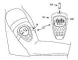
- FIG. 3illustrates the fluid handling device and local controller module of FIG. 1 retained in a fixed position on an arm of a user. Also shown is an exemplary embodiment of a remote controller module according to the present invention.
- FIG. 4is an exploded view of the fluid handling device of FIG. 1 .
- FIG. 5is perspective, partially assembled view of the fluid handling device of FIG. 1 .
- FIG. 6is another perspective, partially assembled view of the fluid handling device of FIG. 1 .
- FIG. 7is a cross sectional view of the fluid handling device of FIG. 1 taken along the section line 7 - 7 of FIG. 5 .
- FIG. 8is an exemplary embodiment of an actuator according to the subject invention.
- FIG. 9is a cross-sectional view of the actuator of FIG. 8 .
- Embodiments of the subject fluid handling devicesinclude a skin piercing element, at least one analyte sensing chamber and a pumping chamber having a deflectable membrane, wherein the pumping chamber is capable of transporting fluid from the skin piercing element to a sensing chamber upon deflection of the deflectable membrane. Also provided are novel kits that include the subject devices.
- embodiments of the subject inventioninclude fluid handling devices, where in many embodiments the fluid handling devices are employed for determining the concentration of an analyte in a fluid.
- Embodiments of the fluid handling devices of the subject inventionprovide for controlled delivery of physiological fluid extracted from a subject, e.g., such as interstitial fluid and the like, to analyte (e.g., glucose) monitoring sensors located within the device, as described below.
- physiological fluidextracted from a subject
- analytee.g., glucose
- Embodiments of the subject inventioninclude a pumping chamber that is capable of transporting fluid from a first region of the device to a second region of the device, where in many embodiments this pumping chamber may be actuated automatically, e.g., by an actuator under the control of a processor.
- the pumping chambermay be employed to controllably start and stop the flow of fluid in a flow pathway, e.g., repeatedly.
- embodimentsinclude devices that are in fluid communication with a skin piercing element, e.g., a skin piercing element may be temporarily (removably) or permanently affixed to the device.
- the pumping chamberis configured to transport fluid from the skin piercing element to a sensing chamber in the device upon actuation of the pumping chamber.
- the subject fluid handling devicesinclude fluid processing features (analyte sensing chambers) for measuring and/or analyzing or otherwise evaluating one or more aspects of a fluid introduced to the device.
- the sensing chamber of the subject fluid handling devicesmay have an electrochemical, photometric or colorimetric configuration by which to perform a measurement on a sampled fluid.
- the subject fluid handling devicesmay be used to process a variety of organic and inorganic fluids as will be apparent to those of skill in the art. It is to be understood that the subject invention is not limited to any particular liquid or type of fluid.
- the fluidsmay be naturally occurring or synthetic, and may be pre-processed or otherwise manipulated prior to use with the subject devices. That is, a wide variety of fluids may be processed (e.g., measured, detected, separated, analyze, and the like) according to the subject invention, where fluids include, but are not limited to, whole blood, interstitial liquid, plasma, buffer or buffer-containing sample, etc.
- a sample of whole blood, interstitial liquid, plasma, cell suspensions, protein solutions, serum, urine, tears, water, buffer or buffer-containing liquid, and the likemay be contacted with a subject device and processes, e.g., for analyte determination.
- the fluidis a bodily fluid such as blood or interstitial fluid.
- the size of a given fluid handling devicemay vary widely depending on the particular analytical protocol performed and, as such, may include small scale or miniaturized devices known in the art.
- the devicesare dimensioned to be comfortably worn or otherwise retained by a user, as described below.
- Embodiments of the subject devicesmay be used with submicroliter, nanoliter and even picoliter amounts of fluid.
- Such fluid handling devicesmay be characterized as microfluidic devices such that they include one or more pathways or channels of extremely small or microfluidic dimensions.
- microfluidicis meant that the device includes one or more liquid pathways or channels, conduits, or reservoirs that has at least one dimension, e.g., depth, width, length, etc., that ranges from about 5 microns to about 2500 microns.
- a fluid pathway of the subject inventionmay have a depth that ranges from about 5 microns to about 500 microns, e.g., from about 25 microns to about 500 microns, and/or a width that may range from about 25 microns to about 500 microns, and/or a length that may range from about 1,000 microns to about 5,000 microns.
- Exemplary microfluidic and other devices that may be adapted for use with the subject inventionare described, e.g., in international publication no. WO 02/49507, as well as U.S. application Ser. No.
- FIG. 1illustrates an exemplary embodiment of a fluid handling device 12 and housing structure 14 , within which device 12 may be operatively loaded, and which in this case is in the form of local controller module 14 .
- Local module 14controls certain functions of device 12 and may be a microprocessor.
- fluid handling device 12has yet to be received by (e.g., inserted partially or completely into) local controller module 14 .
- fluid handling device 12may be received in local controller module 14 .
- device 12may be coupled to the local controller module 14 to enable electrical communication between the local controller module and a device received thereby.
- embodimentsinclude fluid handling device 12 operatively coupled to (e.g., located within and controlled by) local controller module 14 .
- local controller moduleis in electrical and mechanical contact with fluid handling device 12 .
- analyte measurement controlmay be provided by module 14 and/or module 14 may receive measurement data from device 12 such as data related to the concentration determination of an analyte in a fluid contacted with device 12 .
- Connectors or contactsare provided to operatively couple the devices with a local controller module whereby the local controller module provides the requisite signals to the devices to perform the assay measurement and includes a componentry for determining the value of such measurement.
- local module 14may control the functions of device 12 , e.g., actuation of a pumping chamber of the device as will be described, and other functions of device 12 described herein.
- Local controller module 14may be capable of data storage and transmitting and receiving data from another source such as a remote source.
- Local controller module 14is programmable such that an assay protocol performed at a sensor chamber of the device and the timing thereof may be customized according to software algorithms. Such algorithms may provide for the “continuous” monitoring of concentration of an analyte in a user, i.e., for automatically measuring the concentration of an analyte in a user according to a predetermined scheduled, e.g., at two or more points over a given time period or even continuously over a period of about 24 hours, 48 hours, etc.
- embodiments of the subject devicesmay be configured to remain in intimate contact with a user and continuously or periodically obtain sample from the user and monitor one or more analyte concentrations over a given period of time, where in many embodiments sampling and analyte determination are performed automatically according to an algorithm of the device.
- Embodiments of the subject inventionmay also provide for the user to implement an assay “on demand,” thereby overriding the continuous monitoring protocol.
- Such analyte concentration measurementsmay be stored by the microprocessor of module 14 or other memory storage element (such as communicated to a remote location, e.g., to remote controller module 16 described below) for immediate or later retrieval by the user or a physician.
- fluid handling device 12 and local controller module 14may be user-retainable, e.g., they may be worn by a user, such as on the user's arm or the like, e.g., as shown in the figures.
- module 14includes straps 602 for attachment to the arm of a user.
- minutessuch as several minutes or more, e.g., an hour or multiple hours, a day or multiple days or more, etc.
- a device 12 /controller 14 systemmay be worn or retained by a subject for up to about 24 hours or longer.
- Module 14may incorporate other forms of user-retainable elements such as patches, plates, bandages, strips, wraps, sleeves, bracelets, suction cups, and the like. In this manner, embodiments of the subject devices are suited for sustained or continued use by a user. As the subject devices includes on or more analyte sensors, the present invention integrates sensor formats that are amenable to prolonged retention by a patient. Maintaining a subject device in close anatomic association with a user for an extended period through the use of an easily-retainable support allows for constant or periodic monitoring (e.g., analyte monitoring such a glucose monitoring) by a user, physician or other care provider. In many embodiments, this monitoring is accomplished automatically.
- periodic monitoringe.g., analyte monitoring such a glucose monitoring
- local controller module 14may have a skin-facing portion and/or surface which appositions fluid handling device 12 loaded within and fluid handling device 12 may have a skin piercing element affixed thereto for continuous indwelling of the skin piercing element to a section of the user's skin while module 14 /device 12 are maintained at the site of the user.
- Local controller module 14may be configured so as to be maintained against the skin for extended periods, as noted above.
- local controller module 14may have a “watchband”, “legband”, or “armband” configuration in certain embodiments to be worn by a user, e.g., worn on a limbic region, e.g., a wrist or forearm, of the user.
- Housing 14may have a configuration, such as a substantially planar configuration, for adhesive contact with a suitable location, e.g., arm, torso, thigh, hip, etc., on the user's body.
- Local controller module 14may include first data display 406 which may provide audio and/or visual indicators to a user.
- FIG. 2illustrates fluid handling device 12 prior to insertion into local controller module 14 .
- Local controller module 14may be provided with insertion cavity 704 , and may be configured to accept fluid handling device 12 .
- Local controller module 14may be in electrical communication with fluid handling device 12 by way of contact pad 706 on fluid handling device 12 and contact pin 708 located within insertion cavity 704 .
- this electrical communicationmay provide for local module control of aspects of device 12 , e.g., aspects of analyte concentration determination such as timing thereof (e.g., timing of pump actuation, assay timing, etc.).
- local module 14may control aspects of fluid transport of fluid handling device 12 such as the timing of the stop and start of fluid transport from the user through the skin piercing element and to an analyte sensor of the device.
- FIG. 3illustrates attachment of fluid handling device 12 and local controller module 14 onto the arm of a user.
- FIG. 3also illustrates optional remote controller module 16 located within communication range of local controller module 14 .
- Either a physical connection or remote/telemetry type connectionmay be employed to provide communication between remote controller module 16 and local controller module 14 .
- Communication between local controller module 14 and remote controller module 16may be by way of radio frequency (RF), or other wireless means.
- RF signals sent and received by first and second telemetry units, respectivelymay be employed.
- RFradio frequency
- An exemplary system which may be adapted for use in the subject inventionis disclosed in U.S. Pat. No. 6,083,174 to Brehmeier-Flick, the disclosure of which is herein incorporated by reference.
- telemetry units and applications thereof well known in the artare also applicable to the present invention. Regardless, transmission of data to other diagnostic and/or data storage device(s) such as to remote controller module 16 from local controller module 14 may be carried out in any suitable fashion, e.g., in burst or continuous fashion. Telemetry for use in the home is contemplated. In the case of a hospitalized patient, telemetry of data to a central Intensive Care Unit (ICU) station provides another example of use.
- ICUIntensive Care Unit
- Remote controller module 16may include a second data display 508 .
- Display 508may be an audio and/to visual display for displaying results, e.g., analyte measurement results, to a user.
- remote controller module 16may be configured to receive a test strip 516 for determining analyte concentration by way of a received test strip. In this manner, remote controller module 16 may be used with local controller module 16 and device 12 to determine analyte concentration of a fluid applied to device 12 and may be capable of analyte determination of a fluid applied to a test strip received by module 16 .
- fluid handling device 12may be mounted on an arm, or other suitable location of a user, and may be used to monitor an analyte in a bodily fluid such as blood glucose in interstitial fluid.
- a skin piercing elementas noted above may be incorporated into device 12 for piercing, cutting or lancing the skin and, in many embodiments, also includes a fluid collection channel or transfer pathway for transferring the sampled physiological fluid such as for example interstitial fluid within the skin to fluid handling device 12 with which it is operatively associated.
- Skin piercing elements and methods of using skin piercing elementswhich may be adaptable for use with the subject invention, are described for example in U.S. Ser.
- the skin piercing elementmay be any suitable element capable of accessing bodily fluid, e.g., a needle such as small gauge needle, e.g., about 25 to about 30 gauge needle. In certain embodiments, the insertion depth of a needle may range from about 1.5 mm to about 3 mm. In certain embodiments, a skin piercing element may be retractable inside device 12 and may be moved from a first retractable position to a second fluid accessing position outside the device to contact a user. This may be done repeatedly over a given time period to provide periodic analyte monitoring over a period of time.
- Actuation of a skin piercing element from a retracted position to a skin-piercing positionmay be manual or automatic, e.g., may be under the control of local module 14 or remote module 16 .
- advancement of a skin-piercing element to a position for collecting physiological fluid from a usermay be performed manually by the user or driven by a motor controlled by local controller module 14 .
- Such advancement and skin-penetrationmay be done automatically according to a preprogrammed scheduled or at the will of the user in certain embodiments.
- a skin piercing elementis provided to a user already affixed to device 14 or may be provided separately and a user may select a skin piercing element when needed and affix it to fluid handling device 12 .
- a skin piercing elementmay be affixed (e.g., at manufacture or by a user prior to use) about inlet chamber 140 .
- a plurality of skin piercing elementsmay be incorporated into a cartridge associated with fluid handling device 12 .
- a cartridgemay include a plurality of skin piercing elements.
- Device 12 (and/or local controller module 14 )may further provide componentry for operatively moving, e.g., advancing and reversing, a cartridge relative to an aperture of fluid handling device 12 (and/or local controller module 14 ) for exposing and concealing an individual skin-piercing element through the aperture to an access site on the user's skin.
- at least a portion of the apertured devicemay be moveable to expose and unexposed an individual skin-piercing element for fluid sampling.
- the movement of a skin-piercing element relative to a cartridgemay be accomplished passively such as by components fixed within the local controller module relative to the cartridge for advancing or deflecting a skin-piercing element through a device aperture towards an access site on the user, penetrating the access site with the skin-piercing element and then withdrawing or retracting the skin piercing element from the access site.
- Such componentsinclude, but are not limited to, ramp structures and clip mechanisms.
- the timing of skin piercingmay be controlled automatically for example by local controller 14 and/or remote controller 16 such that fluid sampling and analyte determination may be automated.
- suchmay be accomplished passively with respect to a user in that the user need not actively initiate skin piercing and/or physiological fluid flow and/or analyte measuring.
- Thismay be particular convenient for in instances where multiple skin piercing and/or physiological fluid flow and/or analyte measuring cycles need to be performed over a given period, e.g., over about 24 hours, for example for monitoring glucose levels over this period.
- each skin piercing elementmay be operatively attached to the cartridge device so as to be movable relative to the cartridge device so as to optimize the angle by which the skin is to be pierced by the skin-piercing means, thereby reducing pain to the patient and trauma to the skin, e.g., as described in the above-mentioned U.S. patent application Ser. No. 10/143,253.
- FIG. 4is an exploded view of fluid handling device 12 .
- fluid handling device 12includes three parts: pressure disk 10 , elastomeric disk 20 , and sensor disk 30 .
- Pressure disk 10 and sensor disk 30may be rigid, while elastomeric disk 20 may be flexible.
- “Rigid”broadly refers to a substrate which is not flexible, and is constructed such that it cannot be bent along any direction more than about 60 degrees (and often not more than 40, 20, 10, or 5 degrees) without breaking.
- pressure disk 10includes access slot 40 , assembly bosses 50 , and energy directors 55 .
- Elastomeric disk 20includes clearance holes 60 , deflectable pump membrane 70 , inlet channel 90 , sensor chamber 100 , waste channel 110 , and vent 120 .
- Sensor disk 30includes pumping chamber 150 , inlet chamber 140 , and assembly recesses 130 .
- Inlet chamber 140may be in contact with a skin piercing element as described above (not shown) that may be inserted into the tissue of the user, allowing extraction of physiological fluid such as interstitial fluid from the user.
- a skin piercingis in direct or indirect communication with inlet chamber, e.g., inlet chamber may include a skin piercing element, e.g., may be a part of the inlet chamber.
- Pressure disk 10 and sensor disk 30may be fabricated using any suitable technique.
- pressure disk 10 and/or sensor disk 30may be injection molded using thermoplastic polymers. Suitable polymers include, but are not limited to, acrylic, stryrene, polycarbonate, ABS, and polyolefins. Blends of these polymers may also be used. Certain embodiments may employ ultrasonic welding in the assembly of pressure disk 10 to sensor disk 30 . In such instances, polymers may be selected that are amorphous in structure, as opposed to crystalline, as amorphous polymers are more suitable for ultrasonic welding.
- injection moldingis capable of providing product of exacting detail, and may be employed to easily form the features of pressure disk 10 and sensor disk 30 .
- Pressure disk 10 and sensor disk 30may be used as molded, or they may be subjected to post treatment to render their surfaces more hydrophilic.
- Post processesinclude, but are not limited to, exposing the parts to reactive gas plasma or corona, or coating the surfaces with hydrophilic materials.
- Elastomeric disk 20may be fabricated using any suitable technique, e.g., elastomeric disk 20 may be molded, using injection molding or reaction injection molding. Elastomeric disk 20 may also be cast. In any of these methods, the ability to replicate fine detail is necessary. Suitable materials for construction of elastomeric disk 20 include a wide variety of natural and synthetic rubbers, including, but not limited to, silicones, polyurethanes, EPDM, and various polymer blends. In selecting the material, biocompatibility and flexibility are important attributes to consider. If necessary, post treatment may be used to render the surfaces more hydrophilic. If the parts are used as molded, tracks and channels formed in elastomeric disk 20 and sealed with surfaces on pressure disk 10 and sensor disk 30 are less likely to leak, since the parts may be hydrophobic when used as molded.
- access slot 40 in pressure disk 10allows an actuator to make contact with pump membrane 70 in elastomeric disk 20 .
- An actuatormay be provided as part of local controller 14 . Actuation may be performed manually by the user or may be performed automatically, e.g., driven by a motor or the like controlled by the local controller module 14 . Other manners and componentry that enable an actuator to make contact with pump membrane 70 may also be employed. The actuator may make contact on one end of pump membrane 70 , then slide towards the other end, in this way providing a peristaltic pumping motion. Any suitable actuator or technique for actuation may be employed.
- the pumping chamber 150(which may be dish shaped in certain embodiments) has a fixed volume, which may be in the range of nanoliters. Upstream from pumping chamber 150 is connecting channel 155 and downstream is outlet channel 90 which is located in the elastomeric disk 20 . In certain embodiments, actuation may be accomplished as now described with reference to FIGS. 8 and 9 .
- a method of handling a fluidmay include collecting fluid in pumping chamber 150 , e.g., to introduce fresh or new fluid to chamber 150 , optionally pinching pumping chamber 150 to stop the flow of the fluid, collapsing a predetermined length of pumping chamber 150 to dispense a fixed volume of fluid towards a sensor, performing a measurement on the fluid present at the sensor, de-collapse (i.e., stop the collapse of) the predetermined length of pumping chamber 150 and de-pinch (i.e., stop the pinching of) pumping chamber 150 .
- a two-step activationmay be achieved with a single movement.
- connecting channel 155will be closed with the first movement. This will stop the flow of fluid from the inlet.
- pumping membrane 70With further movement of the pinching body 210 , pumping membrane 70 will be squeezed into pumping chamber 150 and the fluid will be pumped along the outlet channel 90 and along the rest of the fluidic structure. In this manner, the pump volume of fresh fluid refreshes the sensor chamber 100 more than once.
- the fluidmay be drawn back from outlet channel 90 into pumping chamber 150 , at which point there is no mixing between “used” and “fresh” fluid, as connecting channel 155 is still closed by the deformation of the pumping membrane 70 by pinching pin 200 .
- pinching pin 200may be removed, thereby opening connecting channel 155 and letting fresh fluid flow into pumping chamber 150 .
- the dispensed volume of fluid(in the pinch-collapse mode) is at least as great as the combined volume of the connecting channel and the sensor volume. This ensures that the sensor is contacted with fresh fluid for analyte sensing.
- the dispensed volume of fluid(in the pinch-collapse mode) may be about 1.5 times or more as large as the combined volume of the connecting channel and the sensor volume, e.g., about 3 times as large, e.g., about 5 times as large, in certain embodiments.
- the amount of pressure required to deflect membrane 70may vary. In certain embodiments, the amount of pressure may range from about 0.1 N to about 10 N.
- Assembly bosses 50 on pressure disk 10include energy directors 55 that are mateable with assembly recesses 130 .
- Energy directorsmay be any suitable shape such as for example conical in shape, and are used to focus pressure and ultrasonic energy. In this way, energy directors 55 and assembly recesses 130 are fused.
- pressure disk 10 and sensor disk 30squeeze elastomeric disk 20 , sealing the channels and chambers that are formed.
- Elastomeric disk 20includes clearance holes 60 , that allow assembly bosses 50 to reach assembly recesses 130 .
- Pump membrane 70forms the top of pumping chamber 150 , thus forming a deformable channel.
- An actuatormay be introduced by way of access slot 40 , deforming pump membrane 70 and forcing fluid out of pumping chamber 150 .
- elastomeric disk 20 and sensor disk 30form inlet channel 90 , sensor chamber 100 , waste channel 110 , and vent 120 .
- Pumping chamber 150is connected to inlet channel 90 , and when actuated, causes fluid to flow from pumping chamber 150 to inlet channel 90 , sensor chamber 100 , and waste channel 110 , or other connected conduits. Air that is displaced flows out of the device by way of vent 120 , preventing a build up of back pressure.
- Sensor chamber 100(Also referred to as a reaction chamber) provides for accumulation of sample from pumping chamber 150 , and overlays a sensor located on sensor disk 30 , i.e., an electrode positioned on sensor disk 30 (e.g., printed thereon) In this particular embodiment, only one sensor chamber is shown. However a plurality of sensor chambers may be employed, e.g., for serial and/or parallel processing of a sample in a plurality of sensor chambers.
- flow of fluidmay be stopped, processed at a sensor chamber, and flow initiated again to transport the fluid to another region where the fluid may be stopped, processed at another reaction chamber, and flow initiated again to transport the fluid to another region, etc., all by way of pumping chamber actuation and de-actuation.
- Sensor chamber 100produces a signal in response to the presence, and concentration of, analyte in physiological fluid present in the chamber.
- the sensor chambermay have a volume in the range from about 25 nL to about 2000 nL.
- Sensor chamber 100may be of any suitable configuration and include any suitable componentry and/or chemicals for generating a signal in response to the presence of analyte in fluid present in the chamber. While in the broadest sense a signal that is indicative of the presence of analyte may be provided, in many embodiments a signal that is proportional to the amount of analyte in the physiological fluid may be provided.
- inlet channel 90When assembled, inlet channel 90 is formed between elastomeric disk 20 and sensor disk 30 .
- Inlet channel 90provides a conduit between pumping chamber 150 and sensor chamber 100 .
- Waste channel 110is formed down stream of sensor chamber 100 , and receives sample after it has passed through sensor chamber 100 .
- Waste channel 110provides space for accumulation of spent sample, such as sample where measurements have been made or where measurements are not desired.
- fluidmay be passed from waste channel 110 to another analyte sensor, e.g., by actuating a pumping chamber, which pumping chamber may be the same or different from one that caused fluid to flow into the waste channel.
- Vent 120is downstream of waste channel 110 , and provides for escape of displaced air to atmosphere. Vent 120 is shown as exiting the disk on its perimeter, but may also exit the assembly through its top or bottom surfaces.
- Sensor disk 30includes assembly recesses 130 that receive assembly bosses 50 when assembled. Assembly recesses 130 are sized to allow adequate clearance for assembly bosses 50 , and include a flat surface that allows contact with energy directors 55 .
- Inlet connector or chamber 140is provided, and is connected to a skin piercing element such as a sampling needle (not shown). In certain embodiments, care should be taken to minimize accumulation of liquid in connector 140 .
- Inlet chamber 140is upstream of pumping chamber 150 which provides space for accumulation of sample from the skin piercing element Accumulation of liquid takes place within chamber 150 as old liquid is replaced with new liquid, as the latter enters via 140 . Inlet chamber 140 is connected to pumping chamber 150 by way of connecting channel 155 .
- Fluidmay be collected from a subject through the skin piercing element, into inlet chamber 140 , and through connecting channel 155 .
- a peristaltic systemmay be employed to provide a negative pressure on actuation, e.g., a seal may be provided that moves across the membrane 70 of the pumping chamber.
- liquidmay flow into chamber 150 partially or solely by inherent liquid pressure.
- pumping chamber 150when actuated, pumping chamber 150 may draw sample from a sampling site of a patient, through the skin piercing element, into inlet chamber 140 , and through connecting channel 155 . But in any event, pumping chamber transports fluid along the fluidic circuit, e.g., to a sensing chamber.
- Pumping chamber 150may be of suitable geometry.
- pumping chamber 150may be convex in geometry.
- Pumping chamber 150may have a volume that ranges from about 20 to about 200 nanoliters, e.g., from about 15 to about 150 nanoliters and may have an internal radius that ranges from about 50 to about 1500 microns, and may have an overall length that ranges from about 1000 to about 5000 microns, in certain embodiments.
- FIG. 5is a partially assembled view of fluid handling device 12 , from a first perspective.
- pressure disk 10 and elastomeric disk 20have been joined.
- Access slot 40is shown and is in direct proximity to pump membrane 70 .
- Assembly bosses 50have passed through clearance holes 60 , and are aligned for contact with assembly recesses 130 .
- Inlet chamber 140 , and pumping chamber 150are shown as features of sensor disk 30 .
- FIG. 6is a partially assembled view of fluid handling device 12 from a second perspective.
- pressure disk 10 and elastomeric disk 20have been joined.
- Access slot 40is shown and is in direct proximity to pump membrane 70 .
- Assembly bosses 50have passed through clearance holes 60 , and are aligned for contact with assembly recesses 130 .
- Inlet chamber 140 , connecting channel 155 , and pumping chamber 150are shown as features of sensor disk 30 .
- Inlet channel 90 , sensor chamber 100 , waste channel 110 , and vent 120are shown in the lower surface of elastomeric disk 20 .
- inlet channel 90connects to pumping chamber 150 at channel edge 190 .
- fluidis drawn through a skin piercing element such as a needle (not shown), into inlet chamber 140 , through connecting channel 155 and into pumping chamber 150 .
- analyte measurementsmay be sensitive to flow.
- measurementsmay be sensitive to flow.
- glucoseis a limiting reactant species.
- glucoseis present in excess, and is not a limiting reactant species. This may cause difficulty when correlating current to glucose concentration in the fluid. For this reason, it may be desirable for measurements to be made when the sample has stopped flowing. Flow of sample may be started and stopped by actuating and not actuating pumping chamber 150 .
- FIG. 7is a cross sectional view of fluid handling device 12 , taken along the section line 7 - 7 of FIG. 5 .
- pressure disk 10elastomeric disk 20
- sensor disk 30have been assembled.
- method of assemblymay include ultrasonic welding, with the polymer from the assembly bosses 50 fusing with the polymer from the assembly recesses 130 . This may be facilitated by way of concentrated ultrasonic energy and pressure at energy directors 55 .
- elastomeric disk 20is compressed between pressure disk 10 and sensor disk 30 .
- Pumping chamber 150is formed between elastomeric disk 20 and sensor disk 30 , with pump membrane 70 forming the top of the chamber. Access to pump membrane 70 by an external actuator is made by way of access slot 40 .
- a subject devicemay be assembled using other methods.
- certain embodimentsmay use adhesive. By placing a layer of pressure sensitive or heat activated adhesive between pressure disk 10 and elastomeric disk 20 , and between elastomeric disk 20 and sensor disk 30 , the three disks may be adhesively joined. Certain embodiments may use external clamping elements to maintain the three components into contact with each other.
- One or more other componentswhich may be integral to the device or separated a distance therefrom, but coupled thereto, such as one or more of, but not limited to, filters, heaters, mixers, and the like, as are well known to those of skill in the art.
- At least a portion of a fluid pathwayincludes a sensing chamber 100 (an analytical portion or compartment or reaction chamber) within which processing of a fluid (e.g., analyte detection and/or measurement) may be performed.
- An analytical portion or compartment or reaction chamberis used herein to refer to a sensor chamber region of a device in which sample processing may be carried out. Examples of functions which may be served by a sensor chamber include, but are not limited to, analyte detection, analyte measurement, chromatographic separations, electrophoretic separations, electrochromatographic separations, and the like.
- a reaction chambermay be characterized as an optical, calorimetric or photometric reaction chamber.
- sensorsmay include one or more reagents of a signal producing system, e.g., on a wall of a chamber, that produces a detectable product in proportion to the amount of analyte present in the chamber. The detectable product may then be optically or photometrically detected to provide for a detection of the presence of analyte, and/or a measurement of the concentration of analyte, that is present in the fluid inside the chamber.
- Such sensorsthat may be employed in the subject invention include, but are not limited to, those described herein and in U.S.
- a signal producing systemmay be made up of a plurality of reagent components that produce a detectable product in the presence of an analyte of interest.
- the signal producing systemmay be an analyte oxidation signal producing system.
- analyte oxidation signal producing systemis meant that in generating the detectable signal from which the analyte concentration in the sample is derived, the analyte is oxidized by a suitable enzyme to produce an oxidized form of the analyte and a corresponding or proportional amount of hydrogen peroxide.
- the hydrogen peroxideis then employed, in turn, to generate the detectable product from one or more indicator compounds, e.g., dye couples, where the amount of detectable product produced by the signal producing system, i.e., the signal, is then related to the amount of analyte in the initial sample.
- indicator compoundse.g., dye couples
- the amount of detectable product produced by the signal producing systemi.e., the signal
- analyte oxidation signal producing systemsmay be characterized as hydrogen peroxide based signal producing systems or peroxide producing signal producing systems.
- the hydrogen peroxide based signal producing systemsmay include an enzyme that oxidizes the analyte and produces a corresponding amount of hydrogen peroxide, where by corresponding amount is meant that the amount of hydrogen peroxide that is produced is proportional to the amount of analyte present in the sample.
- This first enzymenecessarily depends on the nature of the analyte being assayed but is generally an oxidase.
- the enzymemay be: glucose oxidase (where the analyte is glucose); cholesterol oxidase (where the analyte is cholesterol); alcohol oxidase (where the analyte is alcohol); formaldehyde dehydrogenase (where the analyte is formaldehyde), glutamate oxidase (where the analyte is L-glutamic acid), glycerol oxidase (where the analyte is glycerol), galactose oxidase (where the analyte is galactose), a ketoamine oxidase (where the analyte is a glycated protein, e.g., fructosamine), a 3-hydroxybutyrate dehydrogenase (where the analyte is a ketone body), L-ascorbate oxidase (where the analyte is ascorbic acid), lactate oxida
- a signal producing systemsalso includes an enzyme that catalyzes the conversion of a dye substrate into a detectable product in the presence of hydrogen peroxide, where the amount of detectable product that is produced by this reaction is proportional to the amount of hydrogen peroxide that is present.
- This second enzymeis generally a peroxidase, where suitable peroxidases include: horseradish peroxidase (HRP), soy peroxidase, recombinantly produced peroxidase and synthetic analogs having peroxidative activity and the like. See e.g., Ci et al. (1990) Analytica Chimica Acta, 233:299-302.
- the dye substratesare oxidized by hydrogen peroxide in the presence of the peroxidase to produce a product that absorbs light in a predetermined wavelength range, i.e., an indicator dye.
- the indicator dyemay absorb strongly at a wavelength different from that at which the sample or the testing reagent absorbs strongly.
- the oxidized form of the indicatormay be the colored, faintly-colored, or colorless final product that evidences a change in color. That is to say, the testing reagent may indicate the presence of an analyte in a sample by a colored area being bleached or, alternatively, by a colorless area developing color.
- dye substratesinclude, but are not limited to, ANS and MBTH or analogues thereof; MBTH-DMAB; AAP-CTA; and the like. See e.g., in U.S. Pat. Nos. 5,922,530; 5,776,719; 5,563,031; 5,453,360 and 4,962,040; the disclosures of which are herein incorporated by reference.
- Electrochemical sensorsinclude an electrochemical cell that includes two electrodes and one or more reagents of an analyte determination system, where these elements work in concert to produce an electrical current in proportion to the amount of analyte present in the chamber.
- One or more of the electrodesmay be an enzyme coated electrode.
- the generated electrical currentprovides for a detection of the presence of analyte and/or measurement of the concentration of, analyte that is present in the fluid inside the chamber.
- electrochemical measurement systemswhich may be adapted for use with the subject invention are further described, e.g., in U.S. Pat. Nos. 6,521,110; 6,475,360; 6,444,115; 6,620.310; 4,224,125; 4,545,382; 5,266,179; 5,834,224; 5,942,102; and 5,972,199; as well as WO 97/18465 and WO 99/49307; and U.S. patent application Ser. Nos. 09/333,793; 09/497,269 and 09/497,304; the disclosures of which are herein incorporated by reference.
- sensor 100 located on sensor disk 30measures an analyte such as glucose electrochemically.
- the fluidmay be interstitial fluid.
- the sensormay contain a redox reagent system that includes an enzyme and redox active compounds or mediators.
- mediatorsare known in the art, such as ferricyanide, phenazine ethosulphate, phenazine methosulfate, pheylenediamine, 1-methoxy-phenazine methosulfate, 2,6-dimethyl-1,4-benzoquinone, 2,5-dichloro-1,4-benzoquinone, ferrocene derivatives, osmium bipyridyl complexes, and ruthenium complexes.
- Suitable enzymesinclude glucose oxidase and dehydrogenase (both NAD and PQQ based).
- buffering agentse.g., citraconate, citrate, malic, maleic, and phosphate buffers
- divalent cationse.g., calcium chloride, and magnesium chloride
- surfactantse.g., Triton, Macol, Tetronic, Silwet, Zonyl, and Pluronic
- stabilizing agentse.g., albumin, sucrose, trehalose, mannitol and lactose.
- analytes and indicatorsthat may be measured with the sensor include urea, hemoglobin, lactate, alcohol, cholesterol, amino acids, choline, and coagulation factors.
- Embodimentsinclude redox reagents systems that may be positioned in any suitable location of a subject device, i.e., in any flow pathway of a device.
- the enzyme component of the reagentmay be an enzyme or a plurality of enzymes that work in concert to oxidize the analyte of interest.
- the enzyme component of the reagent systemmay be made up of a single analyte oxidizing enzyme or a collection of two or more enzymes that work in concert to oxidize the analyte of interest.
- Enzymes of interestinclude, but are not limited to, oxidases, dehydrogenases, lipases, kinases, diaphorases, quinoproteins and the like.
- the specific enzyme present in the reaction areadepends on the particular analyte for which the electrochemical cell is designed to detect, where representative enzymes include, but are not limited to: glucose oxidase, glucose dehydrogenase, cholesterol esterase, cholesterol oxidase, lipoprotein lipase, glycerol kinase, glycerol-3-phosphate oxidase, lactate oxidase, lactate dehydrogenase, pyruvate oxidase, alcohol oxidase, bilirubin oxidase, uricase, and the like.
- the enzyme component of the reagent systemmay be a glucose oxidizing enzyme (e.g., a glucose oxidase or glucose dehydrogenase).
- the second optional component of a redox reagent systemis a mediator, as referred to above, and which is made up of one or more mediator agents.
- mediator agentsinclude, but are not limited to: ferricyanide, phenazine ethylsulphate, phenazine methylsulfate, phenylenediamine, 1-methoxy-phenazine methylsulfate, 2,6-dimethyl-1,4-benzoquinone, 2,5-dichloro-1,4-benzoquinone, ferrocene derivatives, osmium bipyridyl complexes, ruthenium complexes and the like.
- mediator of ferricyanidmay be employed.
- the subject devicesmay be used in a variety of applications.
- the subject methodsare employed in analyte determination assays in which the presence and/or concentration of an analyte in a fluid is determined.
- Embodiments of the subject inventionprovide a number of advantages, including precise control over initiation and/or flow of a fluid in a fluid pathway, where in many embodiments such is achieved automatically.
- Embodiments of the subject methodsinclude repeatedly (continuously or periodically) obtaining a fluid sample from a subject for analyte determination.
- Embodiments of the subject inventionalso include repeatedly stopping and starting flow of fluid in a flow pathway. In this manner, the flow of liquid in a fluidic circuit may be controlled.
- a skin piercing element in contact with the inlet chamber of a fluid handling deviceis placed in contact with a subject in a manner to pierce the subject's skin to obtain physiological sample.
- the skin piercing elementis affixed to the inlet chamber or otherwise in communication with the chamber.
- Fluidis drawn from the subject into the pumping chamber of the device, e.g., by the inherent pressure of the fluid.
- fluidmay be continuously or periodically drawn from a subject during the time period a user-retainable housing is maintained in contact with a body part of the subject, i.e., during the time period the subject wears a device.
- the fluid present in the pumping chambermay then be transported to a sensing chamber of a device by deflection of the pumping chamber's membrane, as described above.
- Fluidmay be continuously or periodically pumped from the pumping chamber to an analyte sensing chamber, e.g., fresh or new volumes of fluid (e.g., newly collected from a subject) may be continuously or periodically pumped along a fluidic circuit after previously pumped volumes.
- embodiments of the subject inventioninclude insertion of fluid handling device 12 into local controller 14 . This may be performed by a user or fluid handling device 12 may be provided already inserted into controller 14 . Local controller 14 is then placed in contact with a user so that sample may be obtained from a site of user. For example, local controller module 14 may be placed upon the arm of a user or the like and retained thereon by a user retainable support.
- a skin piercing element of fluid handling device 12penetrates into the tissue of the user. This may be achieved simply by placing the controller in contact with skin in certain embodiments (i.e., the skin piercing element may extend from the controller so as to penetrate the skin when so contacted).
- Communicationis established between the local controller 14 and remote controller 16 (if employed), by way of a physical or wireless connection.
- Controlling commandsmay be sent between the remote controller 16 and local controller 14 .
- commandssuch as the timing of the initiation of pumping chamber may be provided, which in turn draws fluid from the user to device 12 .
- An actuatore.g., in local controller 14 , makes mechanical contact with pump membrane 70 by way of access slot 40 .
- a peristaltic type motionmay be provided and sample, such as interstitial fluid, may be drawn from the user through a skin piercing element (not shown) and into inlet chamber 140 , connecting channel 155 , pumping chamber 150 , channel edge 190 , inlet channel 90 , and sensor chamber 100 .
- Representative samplesmay include, but are not limited to, whole blood and interstitial fluid.
- Measurementsmay then be made by a sensor, located on sensor disk 30 and aligned with sensor chamber 100 . Measurements may be made while sample is flowing, or when it is stationary. If it is desired to make measurements while sample is stationary, the actuator may be stopped before measurements are made. To make additional measurements, the actuator may again set in motion, and additional or “fresh” sample may be drawn from the user into the channels and chambers outlined above. Newly drawn sample displaces the previously measured sample. Previously measured sample may accumulate in waste channel 110 , while air escapes through vent 120 . Alternatively, previously measured sample may be further transported to other sensors of the device for additional measurements of the same or different analyte. This method may be repeated as necessary (drawing sample, measuring, drawing new sample measuring . . . ), and may be part of a broader monitoring method. Broader monitoring methods are described in International Application PCT/GB01/05634 (International Publication Number WO 02/49507 A1), which is hereby fully incorporated herein by reference as noted above.
- Results of measurementsmay be stored in a memory of local module 14 or may be communicated to remote controller module 16 .
- datamay be further processed, e.g., componentry may compare a measurement to a threshold value or other reference value and/or perform computations on the measurement data to provide useful information to a user (or physician) about the state of health of the user such as glucose levels.
- results of one or more measurementsare communicated to the user, physician, or the like, by way of display 406 and/or 508 .
- Kit embodimentsmay include one or more subject devices which may or may not be already coupled to a local controller module. Accordingly, certain embodiments may include one or more local controller modules for use with a subject device, where a device and a local controller module may be provided coupled or may be provided separated for coupling by a user at a later time. Embodiments may also include one or more remote controller modules.
- the subject kitsmay further include one or more skin piercing elements for obtaining a physiological sample from a subject.
- a skin piercing elementsmay be provided affixed to a device or may be provided separated for affixing to a device by a user at a later time.
- a skin piercing elementis provided affixed to a device.
- a plurality of skin piercing elementsmay be provided in a cartridge for loading into a device.
- kitsmay also include written instructions for using a device and/or local controller module and/or remote controller module for analyte determination.
- Instructions of a kitmay be printed on a substrate, such as paper or plastic, etc.
- the instructionsmay be present in the kits as a package insert, in the labeling of the container of the kit or components thereof (i.e., associated with the packaging or sub-packaging) etc.
- the instructionsare present as an electronic storage data file present on a suitable computer readable storage medium, e.g., CD-ROM, diskette, etc.
- the actual instructionsare not present in the kit, but means for obtaining the instructions from a remote source, e.g. via the Internet, are provided.
- An example of this embodimentis a kit that includes a web address where the instructions can be viewed and/or from which the instructions can be downloaded. As with the instructions, this means for obtaining the instructions is recorded on a suitable substrate.
- the components of a subject kitmay be packaged in a kit containment element to make a single, easily handled unit, where the kit containment element, e.g., box or analogous structure, may or may not be an airtight container, e.g., to further preserve the integrity (e.g., sterility) of one or more components until use.
- a kit containment elemente.g., box or analogous structure
- the integritye.g., sterility
- Embodiments of the subject inventionprovides for a number of advantages including, but not limited to one or more of, ease of use, versatility with a variety of different applications, and the ability to control the flow of fluid in a flow pathway and the ability to control fluid sampling for analyte determination. As such, the subject invention represents a significant contribution to the art.
Landscapes
- Health & Medical Sciences (AREA)
- Life Sciences & Earth Sciences (AREA)
- Engineering & Computer Science (AREA)
- Physics & Mathematics (AREA)
- General Health & Medical Sciences (AREA)
- Biomedical Technology (AREA)
- Pathology (AREA)
- Molecular Biology (AREA)
- Hematology (AREA)
- Biophysics (AREA)
- Veterinary Medicine (AREA)
- Public Health (AREA)
- Heart & Thoracic Surgery (AREA)
- Animal Behavior & Ethology (AREA)
- Surgery (AREA)
- Medical Informatics (AREA)
- Chemical & Material Sciences (AREA)
- Analytical Chemistry (AREA)
- Manufacturing & Machinery (AREA)
- Chemical Kinetics & Catalysis (AREA)
- Clinical Laboratory Science (AREA)
- Dispersion Chemistry (AREA)
- General Engineering & Computer Science (AREA)
- Mechanical Engineering (AREA)
- Optics & Photonics (AREA)
- Immunology (AREA)
- General Physics & Mathematics (AREA)
- Biochemistry (AREA)
- Emergency Medicine (AREA)
- Medicinal Chemistry (AREA)
- Urology & Nephrology (AREA)
- Food Science & Technology (AREA)
- Electrochemistry (AREA)
- Measurement Of The Respiration, Hearing Ability, Form, And Blood Characteristics Of Living Organisms (AREA)
- Measuring And Recording Apparatus For Diagnosis (AREA)
- Investigating Or Analysing Biological Materials (AREA)
Abstract
Description
Claims (10)
Priority Applications (17)
| Application Number | Priority Date | Filing Date | Title |
|---|---|---|---|
| US10/883,026US8343074B2 (en) | 2004-06-30 | 2004-06-30 | Fluid handling devices |
| US10/883,477US20060000710A1 (en) | 2004-06-30 | 2004-06-30 | Fluid handling methods |
| AU2005202511AAU2005202511A1 (en) | 2004-06-30 | 2005-06-09 | Fluid handling methods |
| AU2005202516AAU2005202516B2 (en) | 2004-06-30 | 2005-06-09 | Fluid handling devices |
| EP05253672.9AEP1611837B1 (en) | 2004-06-30 | 2005-06-14 | Fluid handling devices |
| EP05253661AEP1611836A3 (en) | 2004-06-30 | 2005-06-14 | Fluid handling methods |
| ES05253672.9TES2623951T3 (en) | 2004-06-30 | 2005-06-14 | Fluid Handling Devices |
| CA002510818ACA2510818A1 (en) | 2004-06-30 | 2005-06-22 | Fluid handling methods |
| CA2510821ACA2510821C (en) | 2004-06-30 | 2005-06-22 | Fluid handling devices |
| SG200504092ASG118405A1 (en) | 2004-06-30 | 2005-06-27 | Fluid handling methods |
| SG200504110ASG118413A1 (en) | 2004-06-30 | 2005-06-27 | Fluid handling devices |
| JP2005190289AJP4841876B2 (en) | 2004-06-30 | 2005-06-29 | Liquid handling equipment |
| CN2005100818514ACN1727893B (en) | 2004-06-30 | 2005-06-29 | Fluid treatment device |
| TW094121735ATWI433662B (en) | 2004-06-30 | 2005-06-29 | Fluid handling devices |
| KR1020050056697AKR101233126B1 (en) | 2004-06-30 | 2005-06-29 | Fluid handling device |
| CNA2005100811500ACN1888911A (en) | 2004-06-30 | 2005-06-29 | Fluid treatment method |
| KR1020050057867AKR20060049243A (en) | 2004-06-30 | 2005-06-30 | Fluid handling method |
Applications Claiming Priority (2)
| Application Number | Priority Date | Filing Date | Title |
|---|---|---|---|
| US10/883,026US8343074B2 (en) | 2004-06-30 | 2004-06-30 | Fluid handling devices |
| US10/883,477US20060000710A1 (en) | 2004-06-30 | 2004-06-30 | Fluid handling methods |
Publications (2)
| Publication Number | Publication Date |
|---|---|
| US20060004303A1 US20060004303A1 (en) | 2006-01-05 |
| US8343074B2true US8343074B2 (en) | 2013-01-01 |
Family
ID=35789871
Family Applications (2)
| Application Number | Title | Priority Date | Filing Date |
|---|---|---|---|
| US10/883,026Expired - Fee RelatedUS8343074B2 (en) | 2004-06-30 | 2004-06-30 | Fluid handling devices |
| US10/883,477AbandonedUS20060000710A1 (en) | 2004-06-30 | 2004-06-30 | Fluid handling methods |
Family Applications After (1)
| Application Number | Title | Priority Date | Filing Date |
|---|---|---|---|
| US10/883,477AbandonedUS20060000710A1 (en) | 2004-06-30 | 2004-06-30 | Fluid handling methods |
Country Status (9)
| Country | Link |
|---|---|
| US (2) | US8343074B2 (en) |
| EP (2) | EP1611836A3 (en) |
| JP (1) | JP4841876B2 (en) |
| KR (2) | KR101233126B1 (en) |
| CN (2) | CN1727893B (en) |
| AU (2) | AU2005202516B2 (en) |
| CA (2) | CA2510818A1 (en) |
| SG (2) | SG118413A1 (en) |
| TW (1) | TWI433662B (en) |
Cited By (2)
| Publication number | Priority date | Publication date | Assignee | Title |
|---|---|---|---|---|
| US8708991B2 (en)* | 2010-10-07 | 2014-04-29 | 2301142 Ontario Inc. | Tourniquet with disposable absorbent element |
| US20170007215A1 (en)* | 2014-01-30 | 2017-01-12 | SALVME, Inc. | System for saliva collection |
Families Citing this family (83)
| Publication number | Priority date | Publication date | Assignee | Title |
|---|---|---|---|---|
| US7381184B2 (en) | 2002-11-05 | 2008-06-03 | Abbott Diabetes Care Inc. | Sensor inserter assembly |
| USD902408S1 (en) | 2003-11-05 | 2020-11-17 | Abbott Diabetes Care Inc. | Analyte sensor control unit |
| US9572534B2 (en) | 2010-06-29 | 2017-02-21 | Abbott Diabetes Care Inc. | Devices, systems and methods for on-skin or on-body mounting of medical devices |
| US20090105569A1 (en) | 2006-04-28 | 2009-04-23 | Abbott Diabetes Care, Inc. | Introducer Assembly and Methods of Use |
| US10226207B2 (en) | 2004-12-29 | 2019-03-12 | Abbott Diabetes Care Inc. | Sensor inserter having introducer |
| US8029441B2 (en) | 2006-02-28 | 2011-10-04 | Abbott Diabetes Care Inc. | Analyte sensor transmitter unit configuration for a data monitoring and management system |
| US9743862B2 (en) | 2011-03-31 | 2017-08-29 | Abbott Diabetes Care Inc. | Systems and methods for transcutaneously implanting medical devices |
| US8571624B2 (en) | 2004-12-29 | 2013-10-29 | Abbott Diabetes Care Inc. | Method and apparatus for mounting a data transmission device in a communication system |
| US20090082693A1 (en)* | 2004-12-29 | 2009-03-26 | Therasense, Inc. | Method and apparatus for providing temperature sensor module in a data communication system |
| US7883464B2 (en)* | 2005-09-30 | 2011-02-08 | Abbott Diabetes Care Inc. | Integrated transmitter unit and sensor introducer mechanism and methods of use |
| US7731657B2 (en)* | 2005-08-30 | 2010-06-08 | Abbott Diabetes Care Inc. | Analyte sensor introducer and methods of use |
| US8333714B2 (en) | 2006-09-10 | 2012-12-18 | Abbott Diabetes Care Inc. | Method and system for providing an integrated analyte sensor insertion device and data processing unit |
| US9788771B2 (en) | 2006-10-23 | 2017-10-17 | Abbott Diabetes Care Inc. | Variable speed sensor insertion devices and methods of use |
| US20110190603A1 (en)* | 2009-09-29 | 2011-08-04 | Stafford Gary A | Sensor Inserter Having Introducer |
| US9398882B2 (en)* | 2005-09-30 | 2016-07-26 | Abbott Diabetes Care Inc. | Method and apparatus for providing analyte sensor and data processing device |
| US9259175B2 (en)* | 2006-10-23 | 2016-02-16 | Abbott Diabetes Care, Inc. | Flexible patch for fluid delivery and monitoring body analytes |
| US20110073475A1 (en)* | 2009-08-29 | 2011-03-31 | Abbott Diabetes Care Inc. | Analyte Sensor |
| US8512243B2 (en) | 2005-09-30 | 2013-08-20 | Abbott Diabetes Care Inc. | Integrated introducer and transmitter assembly and methods of use |
| US7697967B2 (en) | 2005-12-28 | 2010-04-13 | Abbott Diabetes Care Inc. | Method and apparatus for providing analyte sensor insertion |
| US20060263839A1 (en)* | 2005-05-17 | 2006-11-23 | Isense Corporation | Combined drug delivery and analyte sensor apparatus |
| US8636672B2 (en)* | 2007-02-28 | 2014-01-28 | Nipro Diagnostics, Inc. | Test strip with integrated lancet |
| FI121698B (en)* | 2005-07-19 | 2011-03-15 | Ihq Innovation Headquarters Oy | Health monitoring device and sensor cassette for the health monitoring device |
| US9521968B2 (en)* | 2005-09-30 | 2016-12-20 | Abbott Diabetes Care Inc. | Analyte sensor retention mechanism and methods of use |
| CA2636034A1 (en) | 2005-12-28 | 2007-10-25 | Abbott Diabetes Care Inc. | Medical device insertion |
| US11298058B2 (en) | 2005-12-28 | 2022-04-12 | Abbott Diabetes Care Inc. | Method and apparatus for providing analyte sensor insertion |
| EP3165247B1 (en)* | 2006-02-09 | 2020-10-28 | DEKA Products Limited Partnership | Pumping fluid delivery systems and methods using force application assembley |
| EP1993437A4 (en)* | 2006-02-24 | 2014-05-14 | Hmicro Inc | A medical signal processing system with distributed wireless sensors |
| US7607243B2 (en)* | 2006-05-03 | 2009-10-27 | Nike, Inc. | Athletic or other performance sensing systems |
| US20070279217A1 (en)* | 2006-06-01 | 2007-12-06 | H-Micro, Inc. | Integrated mobile healthcare system for cardiac care |
| US20080058626A1 (en)* | 2006-09-05 | 2008-03-06 | Shinichi Miyata | Analytical meter with display-based tutorial module |
| US20080058678A1 (en)* | 2006-09-05 | 2008-03-06 | Shinichi Miyata | Kit for the determination of an analyte in a bodily fluid sample that includes a meter with a display-based tutorial module |
| WO2008150917A1 (en) | 2007-05-31 | 2008-12-11 | Abbott Diabetes Care, Inc. | Insertion devices and methods |
| US9046919B2 (en) | 2007-08-20 | 2015-06-02 | Hmicro, Inc. | Wearable user interface device, system, and method of use |
| US8926509B2 (en)* | 2007-08-24 | 2015-01-06 | Hmicro, Inc. | Wireless physiological sensor patches and systems |
| US20110019824A1 (en) | 2007-10-24 | 2011-01-27 | Hmicro, Inc. | Low power radiofrequency (rf) communication systems for secure wireless patch initialization and methods of use |
| US8611319B2 (en) | 2007-10-24 | 2013-12-17 | Hmicro, Inc. | Methods and apparatus to retrofit wired healthcare and fitness systems for wireless operation |
| US20100268043A1 (en)* | 2007-11-07 | 2010-10-21 | Ofer Yodfat | Device and Method for Preventing Diabetic Complications |
| GB0812679D0 (en) | 2008-07-10 | 2008-08-20 | Sec Dep For Innovation Universities | Sample carrier for effecting chemical assays |
| EP2220494B1 (en) | 2007-11-26 | 2011-11-09 | The Secretary Of State For Innovation, Universities And Skills Of Her Majesty's Britannic Government | Electrochemical detection of a metal labelled analyte |
| GB0812681D0 (en)* | 2008-07-10 | 2008-08-20 | Sec Dep For Innovation Universities | Apparatus and methods for effecting chemical assays |
| US9402544B2 (en) | 2009-02-03 | 2016-08-02 | Abbott Diabetes Care Inc. | Analyte sensor and apparatus for insertion of the sensor |
| WO2010095442A1 (en)* | 2009-02-18 | 2010-08-26 | パナソニック株式会社 | Puncture tool, device for measuring biological sample and system for measuring biological sample |
| US20110125058A1 (en)* | 2009-11-24 | 2011-05-26 | Seven Sense Biosystems, Inc. | Patient-enacted sampling technique |
| US20110105952A1 (en)* | 2009-10-30 | 2011-05-05 | Seventh Sense Biosystems, Inc. | Relatively small devices applied to the skin, modular systems, and methods of use thereof |
| US20100256524A1 (en) | 2009-03-02 | 2010-10-07 | Seventh Sense Biosystems, Inc. | Techniques and devices associated with blood sampling |
| US8613892B2 (en) | 2009-06-30 | 2013-12-24 | Abbott Diabetes Care Inc. | Analyte meter with a moveable head and methods of using the same |
| EP3001194B1 (en) | 2009-08-31 | 2019-04-17 | Abbott Diabetes Care, Inc. | Medical devices and methods |
| WO2011026130A1 (en)* | 2009-08-31 | 2011-03-03 | Abbott Diabetes Care Inc. | Inserter device including rotor subassembly |
| WO2011041531A1 (en) | 2009-09-30 | 2011-04-07 | Abbott Diabetes Care Inc. | Interconnect for on-body analyte monitoring device |
| US20110082484A1 (en)* | 2009-10-07 | 2011-04-07 | Heber Saravia | Sensor inserter assembly having rotatable trigger |
| WO2011053787A2 (en)* | 2009-10-30 | 2011-05-05 | Seventh Sense Biosystems, Inc. | Systems and methods for application to skin and control of actuation, delivery and/or perception thereof |
| WO2011053788A2 (en)* | 2009-10-30 | 2011-05-05 | Seventh Sense Biosystems, Inc. | Relatively small devices applied to the skin, modular systems, and methods of use thereof |
| US20110184258A1 (en)* | 2010-01-28 | 2011-07-28 | Abbott Diabetes Care Inc. | Balloon Catheter Analyte Measurement Sensors and Methods for Using the Same |
| WO2011094573A1 (en) | 2010-01-28 | 2011-08-04 | Seventh Sense Biosystems, Inc. | Monitoring or feedback systems and methods |
| USD924406S1 (en) | 2010-02-01 | 2021-07-06 | Abbott Diabetes Care Inc. | Analyte sensor inserter |
| LT3622883T (en) | 2010-03-24 | 2021-08-25 | Abbott Diabetes Care, Inc. | Medical device inserters and processes of inserting and using medical devices |
| WO2011163347A2 (en) | 2010-06-23 | 2011-12-29 | Seventh Sense Biosystems, Inc. | Sampling devices and methods involving relatively little pain |
| US11064921B2 (en) | 2010-06-29 | 2021-07-20 | Abbott Diabetes Care Inc. | Devices, systems and methods for on-skin or on-body mounting of medical devices |
| US20120016308A1 (en) | 2010-07-16 | 2012-01-19 | Seventh Sense Biosystems, Inc. | Low-pressure packaging for fluid devices |
| US20130158482A1 (en) | 2010-07-26 | 2013-06-20 | Seventh Sense Biosystems, Inc. | Rapid delivery and/or receiving of fluids |
| WO2012021801A2 (en) | 2010-08-13 | 2012-02-16 | Seventh Sense Biosystems, Inc. | Systems and techniques for monitoring subjects |
| WO2012064802A1 (en) | 2010-11-09 | 2012-05-18 | Seventh Sense Biosystems, Inc. | Systems and interfaces for blood sampling |
| US8905927B2 (en) | 2010-11-30 | 2014-12-09 | Universal Electronics Inc. | System and method for non-intrusive health monitoring in the home |
| KR102013466B1 (en) | 2011-04-29 | 2019-08-22 | 세븐쓰 센스 바이오시스템즈, 인크. | Delivering and/or receiving fluids |
| US20130158468A1 (en) | 2011-12-19 | 2013-06-20 | Seventh Sense Biosystems, Inc. | Delivering and/or receiving material with respect to a subject surface |
| CN103874461B (en) | 2011-04-29 | 2017-05-10 | 第七感生物系统有限公司 | Devices for collecting and/or manipulating blood spots or other bodily fluids |
| WO2012149155A1 (en) | 2011-04-29 | 2012-11-01 | Seventh Sense Biosystems, Inc. | Systems and methods for collecting fluid from a subject |
| EP2713879B1 (en) | 2011-12-11 | 2017-07-26 | Abbott Diabetes Care, Inc. | Analyte sensor devices, connections, and methods |
| DE102011056271A1 (en)* | 2011-12-12 | 2013-06-13 | sense2care GmbH | Device for analyzing patient samples |
| GB201217390D0 (en) | 2012-09-28 | 2012-11-14 | Agplus Diagnostics Ltd | Test device and sample carrier |
| KR101636356B1 (en)* | 2014-05-30 | 2016-07-07 | 한국원자력연구원 | A gas collector using a chamber and a volumetric column and a gas collecting method thereof |
| WO2015187091A1 (en)* | 2014-06-04 | 2015-12-10 | Chen Hui-Ming | Analysis device and method of operation thereof |
| US10213139B2 (en) | 2015-05-14 | 2019-02-26 | Abbott Diabetes Care Inc. | Systems, devices, and methods for assembling an applicator and sensor control device |
| WO2016183493A1 (en) | 2015-05-14 | 2016-11-17 | Abbott Diabetes Care Inc. | Compact medical device inserters and related systems and methods |
| WO2016196516A1 (en) | 2015-06-03 | 2016-12-08 | William Kenneth Ward | Measurement of glucose in an insulin delivery catheter by minimizing the adverse effects of insulin preservatives |
| TWI624653B (en)* | 2015-12-15 | 2018-05-21 | 台灣歐多貝斯股份有限公司 | Fluid sampling tank and fluid monitoring station |
| CN109682956A (en)* | 2016-01-24 | 2019-04-26 | 余晓飞 | The remote gathering system of human body fluid signal |
| US11071478B2 (en) | 2017-01-23 | 2021-07-27 | Abbott Diabetes Care Inc. | Systems, devices and methods for analyte sensor insertion |
| RU2652561C1 (en)* | 2017-05-30 | 2018-04-26 | Общество С Ограниченной Ответственностью "Континенталь-Мед" | Device for supplying of micro-quantities of a fluid |
| USD1002852S1 (en) | 2019-06-06 | 2023-10-24 | Abbott Diabetes Care Inc. | Analyte sensor device |
| WO2021092966A1 (en)* | 2019-11-16 | 2021-05-20 | 柏兆(吉安)电子有限责任公司 | Blood glucose remote monitoring system based on band-type electronic medical watch |
| CA3188510A1 (en) | 2020-08-31 | 2022-03-03 | Vivek S. RAO | Systems, devices, and methods for analyte sensor insertion |
| USD999913S1 (en) | 2020-12-21 | 2023-09-26 | Abbott Diabetes Care Inc | Analyte sensor inserter |
Citations (155)
| Publication number | Priority date | Publication date | Assignee | Title |
|---|---|---|---|---|
| US3123066A (en) | 1964-03-03 | brumley | ||
| US3136310A (en) | 1960-01-18 | 1964-06-09 | Bausch & Lomb | Optical catheter |
| US3208452A (en) | 1960-09-08 | 1965-09-28 | Panray Parlam Corp | Surface treating device |
| US3338239A (en) | 1964-10-08 | 1967-08-29 | Mine Safety Appliances Co | Surgical puncturing device |
| US3620676A (en) | 1969-02-20 | 1971-11-16 | Sterilizer Control Royalties A | Disposable colorimetric indicator and sampling device for liquids |
| US3640267A (en) | 1969-12-15 | 1972-02-08 | Damon Corp | Clinical sample container |
| US3958560A (en) | 1974-11-25 | 1976-05-25 | Wayne Front March | Non-invasive automatic glucose sensor system |
| US4014321A (en) | 1974-11-25 | 1977-03-29 | March Wayne F | Non-invasive glucose sensor system |
| US4088448A (en) | 1975-09-29 | 1978-05-09 | Lilja Jan Evert | Apparatus for sampling, mixing the sample with a reagent and making particularly optical analyses |
| GB1526708A (en) | 1976-06-18 | 1978-09-27 | Alfa Laval Ab | Method of making reagent test device and reagent test device made according to this method |
| US4195641A (en) | 1977-12-15 | 1980-04-01 | Burton Larry W | Spectroscopic analysis of chemical substances |
| US4200110A (en) | 1977-11-28 | 1980-04-29 | United States Of America | Fiber optic pH probe |
| US4224125A (en) | 1977-09-28 | 1980-09-23 | Matsushita Electric Industrial Co., Ltd. | Enzyme electrode |
| GB2033375B (en) | 1978-10-23 | 1983-03-02 | Johns Manville | Expanding perlite |
| US4407290A (en) | 1981-04-01 | 1983-10-04 | Biox Technology, Inc. | Blood constituent measuring device and method |
| US4420566A (en) | 1982-06-10 | 1983-12-13 | Eastman Kodak Company | Method and apparatus for detecting sample fluid on an analysis slide |
| US4426451A (en) | 1981-01-28 | 1984-01-17 | Eastman Kodak Company | Multi-zoned reaction vessel having pressure-actuatable control means between zones |
| US4480685A (en) | 1980-09-03 | 1984-11-06 | Gilbertson Thomas A | Oil well pump driving unit |
| US4489974A (en) | 1982-09-27 | 1984-12-25 | Warhol John G | Visor assembly including friction mount |
| US4517978A (en) | 1983-01-13 | 1985-05-21 | Levin Paul D | Blood sampling instrument |
| US4545382A (en) | 1981-10-23 | 1985-10-08 | Genetics International, Inc. | Sensor for components of a liquid mixture |
| EP0160768A1 (en) | 1984-05-04 | 1985-11-13 | Kurabo Industries Ltd. | Spectrophotometric apparatus for the non-invasive determination of glucose in body tissues |
| EP0199484A2 (en) | 1985-04-08 | 1986-10-29 | Audio Bionics Inc | Medical system |
| US4622974A (en) | 1984-03-07 | 1986-11-18 | University Of Tennessee Research Corporation | Apparatus and method for in-vivo measurements of chemical concentrations |
| EP0212906A2 (en) | 1985-08-09 | 1987-03-04 | Mitchell P. Dombrowski, M.D. | Blood Sampler |
| US4648408A (en) | 1984-05-11 | 1987-03-10 | Medscan B.V. | Blood sampling unit |
| US4655225A (en) | 1985-04-18 | 1987-04-07 | Kurabo Industries Ltd. | Spectrophotometric method and apparatus for the non-invasive |
| US4660971A (en) | 1984-05-03 | 1987-04-28 | Becton, Dickinson And Company | Optical features of flow cytometry apparatus |
| US4685463A (en) | 1986-04-03 | 1987-08-11 | Williams R Bruce | Device for continuous in vivo measurement of blood glucose concentrations |
| US4704029A (en) | 1985-12-26 | 1987-11-03 | Research Corporation | Blood glucose monitor |
| US4703756A (en) | 1986-05-06 | 1987-11-03 | The Regents Of The University Of California | Complete glucose monitoring system with an implantable, telemetered sensor module |
| DE3708031A1 (en) | 1986-03-20 | 1987-11-12 | Wolfgang Dr Med Wagner | Measurement device or induction device with measurement device, or device for material recovery for a measurement device for metabolic states in the blood by puncturing under reduced pressure in a suction cup with displacement of the measurement zone outside the tip region of the puncturing device |
| EP0250257A1 (en) | 1986-06-19 | 1987-12-23 | Robert Charles Turner | Automatic lancet |
| US4730622A (en) | 1986-07-01 | 1988-03-15 | Cordis Corporation | Pressure and oxygen saturation catheter |
| US4750830A (en) | 1985-11-29 | 1988-06-14 | Lee Arnold St J | Method and apparatus for monitoring blood-glucose concentration by measuring focal properties of the eye |
| US4756884A (en) | 1985-08-05 | 1988-07-12 | Biotrack, Inc. | Capillary flow device |
| US4761381A (en) | 1985-09-18 | 1988-08-02 | Miles Inc. | Volume metering capillary gap device for applying a liquid sample onto a reactive surface |
| US4784577A (en)* | 1986-09-02 | 1988-11-15 | Critikon, Inc. | Pump pressure sensor |
| US4805623A (en) | 1987-09-04 | 1989-02-21 | Vander Corporation | Spectrophotometric method for quantitatively determining the concentration of a dilute component in a light- or other radiation-scattering environment |
| US4849340A (en) | 1987-04-03 | 1989-07-18 | Cardiovascular Diagnostics, Inc. | Reaction system element and method for performing prothrombin time assay |
| US4866129A (en) | 1981-04-07 | 1989-09-12 | Basf Aktiengesellschaft | Impact resistant thermoplastic molding materials |
| US4868129A (en) | 1987-08-27 | 1989-09-19 | Biotrack Inc. | Apparatus and method for dilution and mixing of liquid samples |
| US4873993A (en) | 1986-07-22 | 1989-10-17 | Personal Diagnostics, Inc. | Cuvette |
| US4882492A (en) | 1988-01-19 | 1989-11-21 | Biotronics Associates, Inc. | Non-invasive near infrared measurement of blood analyte concentrations |
| US4883068A (en) | 1988-03-14 | 1989-11-28 | Dec In Tech, Inc. | Blood sampling device and method |
| US4901728A (en) | 1988-05-31 | 1990-02-20 | Eol, Inc. | Personal glucose monitor |
| US4935346A (en) | 1986-08-13 | 1990-06-19 | Lifescan, Inc. | Minimum procedure system for the determination of analytes |
| EP0374115A1 (en) | 1988-12-08 | 1990-06-20 | Humanteknik AB | Positive displacement pump |
| US4953552A (en) | 1989-04-21 | 1990-09-04 | Demarzo Arthur P | Blood glucose monitoring system |
| US4954318A (en) | 1987-08-31 | 1990-09-04 | Minnesota Mining And Manufacturing Company | Optical sensor |
| US4960467A (en) | 1985-02-11 | 1990-10-02 | The United States Of America As Represented By The Secretary Of The Army | Dermal substance collection device |
| US4962040A (en) | 1986-06-04 | 1990-10-09 | Bayer Aktiengesellschaft | 2-hydrazono-4,6-dinitrobenzthiazolones useful to form dyestuffs and as color formers for detecting peroxide |
| US4981779A (en) | 1986-06-26 | 1991-01-01 | Becton, Dickinson And Company | Apparatus for monitoring glucose |
| US5002054A (en) | 1987-02-25 | 1991-03-26 | Ash Medical Systems, Inc. | Interstitial filtration and collection device and method for long-term monitoring of physiological constituents of the body |
| US5014718A (en) | 1988-01-22 | 1991-05-14 | Safety Diagnostics, Inc. | Blood collection and testing method |
| US5026388A (en) | 1989-09-26 | 1991-06-25 | Ingalz Thomas J | Single-use skin puncture device |
| US5029583A (en) | 1986-07-22 | 1991-07-09 | Personal Diagnostics, Inc. | Optical analyzer |
| US5035704A (en) | 1989-03-07 | 1991-07-30 | Lambert Robert D | Blood sampling mechanism |
| US5046508A (en) | 1989-12-19 | 1991-09-10 | Jonathan Weissler | Syringe with retractable needle |
| US5049487A (en) | 1986-08-13 | 1991-09-17 | Lifescan, Inc. | Automated initiation of timing of reflectance readings |
| US5054499A (en) | 1989-03-27 | 1991-10-08 | Swierczek Remi D | Disposable skin perforator and blood testing device |
| EP0453283A1 (en) | 1990-04-19 | 1991-10-23 | Teknekron Sensor Development Corporation | An integral interstitial fluid sensor |
| US5066859A (en) | 1990-05-18 | 1991-11-19 | Karkar Maurice N | Hematocrit and oxygen saturation blood analyzer |
| US5068181A (en) | 1989-12-01 | 1991-11-26 | Akzo N.V. | Method of monitoring reagent delivery in a scanning spectrophotometer |
| US5070886A (en) | 1988-01-22 | 1991-12-10 | Safety Diagnostice, Inc. | Blood collection and testing means |
| US5079421A (en) | 1990-04-19 | 1992-01-07 | Inomet, Inc. | Invasive FTIR blood constituent testing |
| US5096669A (en) | 1988-09-15 | 1992-03-17 | I-Stat Corporation | Disposable sensing device for real time fluid analysis |
| US5104813A (en) | 1989-04-13 | 1992-04-14 | Biotrack, Inc. | Dilution and mixing cartridge |
| US5108926A (en) | 1987-09-08 | 1992-04-28 | Board Of Regents, The University Of Texas System | Apparatus for the precise positioning of cells |
| US5115133A (en) | 1990-04-19 | 1992-05-19 | Inomet, Inc. | Testing of body fluid constituents through measuring light reflected from tympanic membrane |
| US5165419A (en) | 1989-09-26 | 1992-11-24 | Walter Sarstedt Geraete Und Verbrauchsmaterial Fuer Medizin Und Wissenschaft | Blood extraction device |
| US5208163A (en) | 1990-08-06 | 1993-05-04 | Miles Inc. | Self-metering fluid analysis device |
| US5230866A (en) | 1991-03-01 | 1993-07-27 | Biotrack, Inc. | Capillary stop-flow junction having improved stability against accidental fluid flow |
| US5231993A (en) | 1991-11-20 | 1993-08-03 | Habley Medical Technology Corporation | Blood sampler and component tester with guide member |
| US5242606A (en) | 1990-06-04 | 1993-09-07 | Abaxis, Incorporated | Sample metering port for analytical rotor having overflow chamber |
| US5252044A (en) | 1992-10-20 | 1993-10-12 | Medflow, Inc. | Parenteral fluid pump with disposable cassette |
| US5266179A (en) | 1990-07-20 | 1993-11-30 | Matsushita Electric Industrial Co., Ltd. | Quantitative analysis method and its system using a disposable sensor |
| EP0582226A1 (en) | 1992-08-03 | 1994-02-09 | Przedsiebiorstwo Zagraniczne Htl | Lancet device |
| US5302093A (en) | 1992-05-01 | 1994-04-12 | Mcgaw, Inc. | Disposable cassette with negative head height fluid supply and method |
| US5309176A (en) | 1992-08-25 | 1994-05-03 | Sci Systems, Inc. | Airline ticket printer with stepper motor for selectively engaging print head and platen |
| US5320607A (en) | 1992-02-13 | 1994-06-14 | Kabushiki Kaisya Advance | Simple blood sampling device |
| US5338688A (en) | 1990-08-02 | 1994-08-16 | Boehringer Mannheim Gmbh | Method for the metered application of a biochemical analytical liquid to a target |
| US5368047A (en) | 1993-04-28 | 1994-11-29 | Nissho Corporation | Suction-type blood sampler |
| US5378638A (en) | 1990-08-02 | 1995-01-03 | Boehringer Mannheim Gmbh | Analysis element and process for its manufacture |
| US5437841A (en) | 1991-05-07 | 1995-08-01 | Hoffmann-La Roche Inc. | Cuvette |
| US5453360A (en) | 1992-02-03 | 1995-09-26 | Lifescan, Inc. | Oxidative coupling dye for spectrophotometric quantitive analysis of analytes |
| US5458140A (en) | 1993-11-15 | 1995-10-17 | Non-Invasive Monitoring Company (Nimco) | Enhancement of transdermal monitoring applications with ultrasound and chemical enhancers |
| US5470757A (en) | 1991-06-25 | 1995-11-28 | Minnesota Mining And Manufacturing Company | Spectroscopic sample holder and method for using same |
| US5472603A (en) | 1992-04-02 | 1995-12-05 | Abaxis, Inc. | Analytical rotor with dye mixing chamber |
| US5504011A (en) | 1994-10-21 | 1996-04-02 | International Technidyne Corporation | Portable test apparatus and associated method of performing a blood coagulation test |
| US5508521A (en) | 1994-12-05 | 1996-04-16 | Cardiovascular Diagnostics Inc. | Method and apparatus for detecting liquid presence on a reflecting surface using modulated light |
| US5509394A (en) | 1993-02-03 | 1996-04-23 | Mazda Motor Corporation | Internal combustion engine with supercharger |
| US5563031A (en) | 1994-09-08 | 1996-10-08 | Lifescan, Inc. | Highly stable oxidative coupling dye for spectrophotometric determination of analytes |
| US5575632A (en)* | 1994-09-12 | 1996-11-19 | Ivac Medical Systems, Inc. | Engineered pumping segment |
| US5582184A (en) | 1993-10-13 | 1996-12-10 | Integ Incorporated | Interstitial fluid collection and constituent measurement |
| US5627041A (en) | 1994-09-02 | 1997-05-06 | Biometric Imaging, Inc. | Disposable cartridge for an assay of a biological sample |
| US5628961A (en) | 1993-10-28 | 1997-05-13 | I-Stat Corporation | Apparatus for assaying viscosity changes in fluid samples and method of conducting same |
| US5638828A (en) | 1993-10-28 | 1997-06-17 | I-Stat Corporation | Fluid sample collection and introduction device and method |
| US5674699A (en) | 1993-06-08 | 1997-10-07 | Chronomed, Inc. | Two-phase optical assay |
| US5677195A (en) | 1991-11-22 | 1997-10-14 | Affymax Technologies N.V. | Combinatorial strategies for polymer synthesis |
| US5682233A (en) | 1995-09-08 | 1997-10-28 | Integ, Inc. | Interstitial fluid sampler |
| US5700695A (en) | 1994-06-30 | 1997-12-23 | Zia Yassinzadeh | Sample collection and manipulation method |
| US5708278A (en) | 1996-05-13 | 1998-01-13 | Johnson & Johnson Clinical Diagnostics, Inc. | Reflective wetness detector |
| US5728352A (en) | 1994-11-14 | 1998-03-17 | Advanced Care Products | Disposable electronic diagnostic instrument |
| US5736404A (en) | 1995-12-27 | 1998-04-07 | Zia Yassinzadeh | Flow detection appartus and method |
| US5776719A (en) | 1997-07-07 | 1998-07-07 | Mercury Diagnostics, Inc. | Diagnostic compositions and devices utilizing same |
| US5789255A (en) | 1995-10-17 | 1998-08-04 | Lifescan, Inc. | Blood glucose strip having reduced sensitivity to hematocrit |
| US5834224A (en) | 1994-08-24 | 1998-11-10 | Boehringer Mannhein Gmbh | Electrochemical sensor containing an enzyme linked to binding molecules bound to a noble metal surface |
| US5879310A (en) | 1995-09-08 | 1999-03-09 | Integ, Inc. | Body fluid sampler |
| US5879367A (en) | 1995-09-08 | 1999-03-09 | Integ, Inc. | Enhanced interstitial fluid collection |
| EP0922954A2 (en) | 1997-12-10 | 1999-06-16 | UMM Electronics, Inc. | Method for recognizing the presence of sample fluid on a test strip by evaluating first and second derivatives |
| US5922530A (en) | 1994-09-08 | 1999-07-13 | Lifescan, Inc. | Stable coupling dye for photometric determination of analytes |
| US5942102A (en) | 1995-11-16 | 1999-08-24 | Usf Filtration And Separations Group Inc. | Electrochemical method |
| US5972199A (en) | 1995-10-11 | 1999-10-26 | E. Heller & Company | Electrochemical analyte sensors using thermostable peroxidase |
| US6001307A (en) | 1996-04-26 | 1999-12-14 | Kyoto Daiichi Kagaku Co., Ltd. | Device for analyzing a sample |
| EP0974840A2 (en) | 1998-07-20 | 2000-01-26 | Lifescan, Inc. | Fluidic device for medical diagnostics |
| US6033866A (en) | 1997-12-08 | 2000-03-07 | Biomedix, Inc. | Highly sensitive amperometric bi-mediator-based glucose biosensor |
| US6066504A (en) | 1997-06-27 | 2000-05-23 | Hemosense, Inc. | Coagulation or lysis assays using an electroactive species |
| US6084660A (en) | 1998-07-20 | 2000-07-04 | Lifescan, Inc. | Initiation of an analytical measurement in blood |
| US6083174A (en) | 1997-02-13 | 2000-07-04 | Sican Gmbh | Implantable measuring unit for intracorporal measurement of patient data |
| US6193873B1 (en) | 1999-06-15 | 2001-02-27 | Lifescan, Inc. | Sample detection to initiate timing of an electrochemical assay |
| US6206841B1 (en)* | 1996-12-06 | 2001-03-27 | Abbott Laboratories | Method and apparatus for obtaining blood for diagnostic tests |
| US6261519B1 (en) | 1998-07-20 | 2001-07-17 | Lifescan, Inc. | Medical diagnostic device with enough-sample indicator |
| US6312888B1 (en) | 1998-06-10 | 2001-11-06 | Abbott Laboratories | Diagnostic assay for a sample of biological fluid |
| US6335203B1 (en) | 1994-09-08 | 2002-01-01 | Lifescan, Inc. | Optically readable strip for analyte detection having on-strip orientation index |
| US6362890B1 (en) | 1999-06-14 | 2002-03-26 | Roche Diagnostics Gmbh | Method and device for checking the liquid take up of a test layer of an analysis element |
| US20020114738A1 (en) | 2000-10-25 | 2002-08-22 | Wyzgol Raimund C. | Structures for precisely controlled transport of fluids |
| US6444115B1 (en) | 2000-07-14 | 2002-09-03 | Lifescan, Inc. | Electrochemical method for measuring chemical reaction rates |
| US20020143437A1 (en) | 2001-03-28 | 2002-10-03 | Kalyan Handique | Methods and systems for control of microfluidic devices |
| US6475372B1 (en) | 2000-02-02 | 2002-11-05 | Lifescan, Inc. | Electrochemical methods and devices for use in the determination of hematocrit corrected analyte concentrations |
| US6475360B1 (en) | 1998-03-12 | 2002-11-05 | Lifescan, Inc. | Heated electrochemical cell |
| US20020169411A1 (en)* | 2001-05-11 | 2002-11-14 | The Procter & Gamble Co. | Portable interstitial fluid monitoring system |
| US6488827B1 (en) | 2000-03-31 | 2002-12-03 | Lifescan, Inc. | Capillary flow control in a medical diagnostic device |
| EP1279436A2 (en) | 2001-07-24 | 2003-01-29 | Lg Electronics Inc. | Handling and delivering fluid through a microchannel in an elastic substrate by progressively squeezing the microchannel along its length |
| US20030023189A1 (en)* | 2001-05-14 | 2003-01-30 | Youti Kuo | Handheld diagnostic device with renewable biosensor |
| US6521110B1 (en) | 1995-11-16 | 2003-02-18 | Lifescan, Inc. | Electrochemical cell |
| US20030044318A1 (en) | 2001-09-05 | 2003-03-06 | Lorin Olson | Devices for analyte concentration determination and methods of using the same |
| US6531322B1 (en) | 1998-08-13 | 2003-03-11 | Lifescan, Inc. | Visual blood glucose test strip |
| US6541266B2 (en) | 2001-02-28 | 2003-04-01 | Home Diagnostics, Inc. | Method for determining concentration of an analyte in a test strip |
| US20030073931A1 (en) | 2001-10-16 | 2003-04-17 | Dirk Boecker | Universal diagnostic platform |
| US6554789B1 (en)* | 1997-02-14 | 2003-04-29 | Nxstage Medical, Inc. | Layered fluid circuit assemblies and methods for making them |
| US20030083685A1 (en) | 2001-06-12 | 2003-05-01 | Freeman Dominique M. | Sampling module device and method |
| US20030141473A1 (en) | 2002-01-31 | 2003-07-31 | Pelrine Ronald E. | Devices and methods for controlling fluid flow using elastic sheet deflection |
| US6620310B1 (en) | 2000-12-13 | 2003-09-16 | Lifescan, Inc. | Electrochemical coagulation assay and device |
| US20030212379A1 (en)* | 2002-02-26 | 2003-11-13 | Bylund Adam David | Systems and methods for remotely controlling medication infusion and analyte monitoring |
| US20030212347A1 (en) | 2002-05-09 | 2003-11-13 | Borzu Sohrab | Devices and methods for accessing and analyzing physiological fluid |
| US6652814B1 (en) | 2000-08-11 | 2003-11-25 | Lifescan, Inc. | Strip holder for use in a test strip meter |
| US6656697B1 (en) | 1998-09-28 | 2003-12-02 | Lifescan, Inc. | Diagnostics based on tetrazolium compounds |
| US6706159B2 (en)* | 2000-03-02 | 2004-03-16 | Diabetes Diagnostics | Combined lancet and electrochemical analyte-testing apparatus |
| US6716577B1 (en) | 2000-02-02 | 2004-04-06 | Lifescan, Inc. | Electrochemical test strip for use in analyte determination |
| US20040096959A1 (en) | 2000-12-19 | 2004-05-20 | Matthias Stiene | Analyte measurement |
| US6743597B1 (en) | 2000-06-13 | 2004-06-01 | Lifescan, Inc. | Compositions containing a urea derivative dye for detecting an analyte and methods for using the same |
| US20040204662A1 (en)* | 1997-11-21 | 2004-10-14 | Perez Edward P. | Methods and apparatus for expressing body fluid from an incision |
| EP1260815A3 (en) | 2001-05-25 | 2005-03-23 | Lifescan, Inc. | Methods for automatically monitoring analyte concentration using minimally invasive devices |
| US6872297B2 (en)* | 2001-05-31 | 2005-03-29 | Instrumentation Laboratory Company | Analytical instruments, biosensors and methods thereof |
Family Cites Families (5)
| Publication number | Priority date | Publication date | Assignee | Title |
|---|---|---|---|---|
| US558375A (en) | 1896-04-14 | Alvin l | ||
| US448974A (en)* | 1891-03-24 | Puzzle | ||
| JPH10333508A (en)* | 1997-05-30 | 1998-12-18 | Toshiba Corp | Image forming device |
| AUPP250398A0 (en) | 1998-03-20 | 1998-04-23 | Usf Filtration And Separations Group Inc. | Sensor with improved shelf life |
| SE524730C2 (en)* | 2002-11-20 | 2004-09-21 | Boule Medical Ab | Blood Unit |
- 2004
- 2004-06-30USUS10/883,026patent/US8343074B2/ennot_activeExpired - Fee Related
- 2004-06-30USUS10/883,477patent/US20060000710A1/ennot_activeAbandoned
- 2005
- 2005-06-09AUAU2005202516Apatent/AU2005202516B2/ennot_activeCeased
- 2005-06-09AUAU2005202511Apatent/AU2005202511A1/ennot_activeAbandoned
- 2005-06-14EPEP05253661Apatent/EP1611836A3/ennot_activeWithdrawn
- 2005-06-14EPEP05253672.9Apatent/EP1611837B1/ennot_activeExpired - Lifetime
- 2005-06-22CACA002510818Apatent/CA2510818A1/ennot_activeAbandoned
- 2005-06-22CACA2510821Apatent/CA2510821C/ennot_activeExpired - Fee Related
- 2005-06-27SGSG200504110Apatent/SG118413A1/enunknown
- 2005-06-27SGSG200504092Apatent/SG118405A1/enunknown
- 2005-06-29JPJP2005190289Apatent/JP4841876B2/ennot_activeExpired - Fee Related
- 2005-06-29CNCN2005100818514Apatent/CN1727893B/ennot_activeExpired - Fee Related
- 2005-06-29CNCNA2005100811500Apatent/CN1888911A/enactivePending
- 2005-06-29KRKR1020050056697Apatent/KR101233126B1/ennot_activeExpired - Fee Related
- 2005-06-29TWTW094121735Apatent/TWI433662B/ennot_activeIP Right Cessation
- 2005-06-30KRKR1020050057867Apatent/KR20060049243A/ennot_activeWithdrawn
Patent Citations (179)
| Publication number | Priority date | Publication date | Assignee | Title |
|---|---|---|---|---|
| US3123066A (en) | 1964-03-03 | brumley | ||
| US3136310A (en) | 1960-01-18 | 1964-06-09 | Bausch & Lomb | Optical catheter |
| US3208452A (en) | 1960-09-08 | 1965-09-28 | Panray Parlam Corp | Surface treating device |
| US3338239A (en) | 1964-10-08 | 1967-08-29 | Mine Safety Appliances Co | Surgical puncturing device |
| US3620676A (en) | 1969-02-20 | 1971-11-16 | Sterilizer Control Royalties A | Disposable colorimetric indicator and sampling device for liquids |
| US3640267A (en) | 1969-12-15 | 1972-02-08 | Damon Corp | Clinical sample container |
| US3958560A (en) | 1974-11-25 | 1976-05-25 | Wayne Front March | Non-invasive automatic glucose sensor system |
| US4014321A (en) | 1974-11-25 | 1977-03-29 | March Wayne F | Non-invasive glucose sensor system |
| US4088448A (en) | 1975-09-29 | 1978-05-09 | Lilja Jan Evert | Apparatus for sampling, mixing the sample with a reagent and making particularly optical analyses |
| GB1526708A (en) | 1976-06-18 | 1978-09-27 | Alfa Laval Ab | Method of making reagent test device and reagent test device made according to this method |
| US4224125A (en) | 1977-09-28 | 1980-09-23 | Matsushita Electric Industrial Co., Ltd. | Enzyme electrode |
| US4200110A (en) | 1977-11-28 | 1980-04-29 | United States Of America | Fiber optic pH probe |
| US4195641A (en) | 1977-12-15 | 1980-04-01 | Burton Larry W | Spectroscopic analysis of chemical substances |
| GB2033375B (en) | 1978-10-23 | 1983-03-02 | Johns Manville | Expanding perlite |
| US4480685A (en) | 1980-09-03 | 1984-11-06 | Gilbertson Thomas A | Oil well pump driving unit |
| US4426451A (en) | 1981-01-28 | 1984-01-17 | Eastman Kodak Company | Multi-zoned reaction vessel having pressure-actuatable control means between zones |
| US4407290A (en) | 1981-04-01 | 1983-10-04 | Biox Technology, Inc. | Blood constituent measuring device and method |
| US4407290B1 (en) | 1981-04-01 | 1986-10-14 | ||
| US4866129A (en) | 1981-04-07 | 1989-09-12 | Basf Aktiengesellschaft | Impact resistant thermoplastic molding materials |
| US4545382A (en) | 1981-10-23 | 1985-10-08 | Genetics International, Inc. | Sensor for components of a liquid mixture |
| US4420566A (en) | 1982-06-10 | 1983-12-13 | Eastman Kodak Company | Method and apparatus for detecting sample fluid on an analysis slide |
| US4489974A (en) | 1982-09-27 | 1984-12-25 | Warhol John G | Visor assembly including friction mount |
| US4517978A (en) | 1983-01-13 | 1985-05-21 | Levin Paul D | Blood sampling instrument |
| US4622974A (en) | 1984-03-07 | 1986-11-18 | University Of Tennessee Research Corporation | Apparatus and method for in-vivo measurements of chemical concentrations |
| US4660971A (en) | 1984-05-03 | 1987-04-28 | Becton, Dickinson And Company | Optical features of flow cytometry apparatus |
| EP0160768A1 (en) | 1984-05-04 | 1985-11-13 | Kurabo Industries Ltd. | Spectrophotometric apparatus for the non-invasive determination of glucose in body tissues |
| US4648408A (en) | 1984-05-11 | 1987-03-10 | Medscan B.V. | Blood sampling unit |
| US4960467A (en) | 1985-02-11 | 1990-10-02 | The United States Of America As Represented By The Secretary Of The Army | Dermal substance collection device |
| US4637403A (en) | 1985-04-08 | 1987-01-20 | Garid, Inc. | Glucose medical monitoring system |
| EP0199484A2 (en) | 1985-04-08 | 1986-10-29 | Audio Bionics Inc | Medical system |
| US4655225A (en) | 1985-04-18 | 1987-04-07 | Kurabo Industries Ltd. | Spectrophotometric method and apparatus for the non-invasive |
| US4756884A (en) | 1985-08-05 | 1988-07-12 | Biotrack, Inc. | Capillary flow device |
| EP0212906A2 (en) | 1985-08-09 | 1987-03-04 | Mitchell P. Dombrowski, M.D. | Blood Sampler |
| US4761381A (en) | 1985-09-18 | 1988-08-02 | Miles Inc. | Volume metering capillary gap device for applying a liquid sample onto a reactive surface |
| US4750830A (en) | 1985-11-29 | 1988-06-14 | Lee Arnold St J | Method and apparatus for monitoring blood-glucose concentration by measuring focal properties of the eye |
| US4704029A (en) | 1985-12-26 | 1987-11-03 | Research Corporation | Blood glucose monitor |
| DE3708031A1 (en) | 1986-03-20 | 1987-11-12 | Wolfgang Dr Med Wagner | Measurement device or induction device with measurement device, or device for material recovery for a measurement device for metabolic states in the blood by puncturing under reduced pressure in a suction cup with displacement of the measurement zone outside the tip region of the puncturing device |
| US4685463A (en) | 1986-04-03 | 1987-08-11 | Williams R Bruce | Device for continuous in vivo measurement of blood glucose concentrations |
| US4703756A (en) | 1986-05-06 | 1987-11-03 | The Regents Of The University Of California | Complete glucose monitoring system with an implantable, telemetered sensor module |
| US4962040A (en) | 1986-06-04 | 1990-10-09 | Bayer Aktiengesellschaft | 2-hydrazono-4,6-dinitrobenzthiazolones useful to form dyestuffs and as color formers for detecting peroxide |
| EP0250257A1 (en) | 1986-06-19 | 1987-12-23 | Robert Charles Turner | Automatic lancet |
| US4981779A (en) | 1986-06-26 | 1991-01-01 | Becton, Dickinson And Company | Apparatus for monitoring glucose |
| US4730622A (en) | 1986-07-01 | 1988-03-15 | Cordis Corporation | Pressure and oxygen saturation catheter |
| US5029583A (en) | 1986-07-22 | 1991-07-09 | Personal Diagnostics, Inc. | Optical analyzer |
| US4873993A (en) | 1986-07-22 | 1989-10-17 | Personal Diagnostics, Inc. | Cuvette |
| US5426032A (en) | 1986-08-13 | 1995-06-20 | Lifescan, Inc. | No-wipe whole blood glucose test strip |
| US5049487A (en) | 1986-08-13 | 1991-09-17 | Lifescan, Inc. | Automated initiation of timing of reflectance readings |
| US5179005A (en) | 1986-08-13 | 1993-01-12 | Lifescan, Inc. | Minimum procedure system for the determination of analytes |
| US4935346A (en) | 1986-08-13 | 1990-06-19 | Lifescan, Inc. | Minimum procedure system for the determination of analytes |
| US5563042A (en) | 1986-08-13 | 1996-10-08 | Lifescan, Inc. | Whole blood glucose test strip |
| US5304468A (en) | 1986-08-13 | 1994-04-19 | Lifescan, Inc. | Reagent test strip and apparatus for determination of blood glucose |
| US5968760A (en) | 1986-08-13 | 1999-10-19 | Lifescan, Inc. | Temperature-Independent Blood Glucose Measurement |
| US5843692A (en) | 1986-08-13 | 1998-12-01 | Lifescan, Inc. | Automatic initiation of a time interval for measuring glucose concentration in a sample of whole blood |
| US4784577A (en)* | 1986-09-02 | 1988-11-15 | Critikon, Inc. | Pump pressure sensor |
| US5002054A (en) | 1987-02-25 | 1991-03-26 | Ash Medical Systems, Inc. | Interstitial filtration and collection device and method for long-term monitoring of physiological constituents of the body |
| US4849340A (en) | 1987-04-03 | 1989-07-18 | Cardiovascular Diagnostics, Inc. | Reaction system element and method for performing prothrombin time assay |
| US4868129A (en) | 1987-08-27 | 1989-09-19 | Biotrack Inc. | Apparatus and method for dilution and mixing of liquid samples |
| US4954318A (en) | 1987-08-31 | 1990-09-04 | Minnesota Mining And Manufacturing Company | Optical sensor |
| US4805623A (en) | 1987-09-04 | 1989-02-21 | Vander Corporation | Spectrophotometric method for quantitatively determining the concentration of a dilute component in a light- or other radiation-scattering environment |
| US5108926A (en) | 1987-09-08 | 1992-04-28 | Board Of Regents, The University Of Texas System | Apparatus for the precise positioning of cells |
| US4882492A (en) | 1988-01-19 | 1989-11-21 | Biotronics Associates, Inc. | Non-invasive near infrared measurement of blood analyte concentrations |
| US5014718A (en) | 1988-01-22 | 1991-05-14 | Safety Diagnostics, Inc. | Blood collection and testing method |
| US5070886A (en) | 1988-01-22 | 1991-12-10 | Safety Diagnostice, Inc. | Blood collection and testing means |
| US4883068A (en) | 1988-03-14 | 1989-11-28 | Dec In Tech, Inc. | Blood sampling device and method |
| US4901728A (en) | 1988-05-31 | 1990-02-20 | Eol, Inc. | Personal glucose monitor |
| US5096669A (en) | 1988-09-15 | 1992-03-17 | I-Stat Corporation | Disposable sensing device for real time fluid analysis |
| EP0374115A1 (en) | 1988-12-08 | 1990-06-20 | Humanteknik AB | Positive displacement pump |
| US5035704A (en) | 1989-03-07 | 1991-07-30 | Lambert Robert D | Blood sampling mechanism |
| US5201324A (en) | 1989-03-27 | 1993-04-13 | Remi Swierczek | Disposable skin perforator and blood testing device |
| US5054499A (en) | 1989-03-27 | 1991-10-08 | Swierczek Remi D | Disposable skin perforator and blood testing device |
| US5104813A (en) | 1989-04-13 | 1992-04-14 | Biotrack, Inc. | Dilution and mixing cartridge |
| US4953552A (en) | 1989-04-21 | 1990-09-04 | Demarzo Arthur P | Blood glucose monitoring system |
| US5026388A (en) | 1989-09-26 | 1991-06-25 | Ingalz Thomas J | Single-use skin puncture device |
| US5165419A (en) | 1989-09-26 | 1992-11-24 | Walter Sarstedt Geraete Und Verbrauchsmaterial Fuer Medizin Und Wissenschaft | Blood extraction device |
| US5068181A (en) | 1989-12-01 | 1991-11-26 | Akzo N.V. | Method of monitoring reagent delivery in a scanning spectrophotometer |
| US5046508A (en) | 1989-12-19 | 1991-09-10 | Jonathan Weissler | Syringe with retractable needle |
| US5115133A (en) | 1990-04-19 | 1992-05-19 | Inomet, Inc. | Testing of body fluid constituents through measuring light reflected from tympanic membrane |
| US5179951A (en) | 1990-04-19 | 1993-01-19 | Inomet, Inc. | Blood constituent measurement |
| EP0453283A1 (en) | 1990-04-19 | 1991-10-23 | Teknekron Sensor Development Corporation | An integral interstitial fluid sensor |
| US5079421A (en) | 1990-04-19 | 1992-01-07 | Inomet, Inc. | Invasive FTIR blood constituent testing |
| US5146091A (en) | 1990-04-19 | 1992-09-08 | Inomet, Inc. | Body fluid constituent measurement utilizing an interference pattern |
| US5066859A (en) | 1990-05-18 | 1991-11-19 | Karkar Maurice N | Hematocrit and oxygen saturation blood analyzer |
| US5242606A (en) | 1990-06-04 | 1993-09-07 | Abaxis, Incorporated | Sample metering port for analytical rotor having overflow chamber |
| US5266179A (en) | 1990-07-20 | 1993-11-30 | Matsushita Electric Industrial Co., Ltd. | Quantitative analysis method and its system using a disposable sensor |
| US5338688A (en) | 1990-08-02 | 1994-08-16 | Boehringer Mannheim Gmbh | Method for the metered application of a biochemical analytical liquid to a target |
| US5378638A (en) | 1990-08-02 | 1995-01-03 | Boehringer Mannheim Gmbh | Analysis element and process for its manufacture |
| US5208163A (en) | 1990-08-06 | 1993-05-04 | Miles Inc. | Self-metering fluid analysis device |
| US5230866A (en) | 1991-03-01 | 1993-07-27 | Biotrack, Inc. | Capillary stop-flow junction having improved stability against accidental fluid flow |
| US5437841A (en) | 1991-05-07 | 1995-08-01 | Hoffmann-La Roche Inc. | Cuvette |
| US5470757A (en) | 1991-06-25 | 1995-11-28 | Minnesota Mining And Manufacturing Company | Spectroscopic sample holder and method for using same |
| US5231993A (en) | 1991-11-20 | 1993-08-03 | Habley Medical Technology Corporation | Blood sampler and component tester with guide member |
| US5677195A (en) | 1991-11-22 | 1997-10-14 | Affymax Technologies N.V. | Combinatorial strategies for polymer synthesis |
| US5453360A (en) | 1992-02-03 | 1995-09-26 | Lifescan, Inc. | Oxidative coupling dye for spectrophotometric quantitive analysis of analytes |
| US5320607A (en) | 1992-02-13 | 1994-06-14 | Kabushiki Kaisya Advance | Simple blood sampling device |
| US5472603A (en) | 1992-04-02 | 1995-12-05 | Abaxis, Inc. | Analytical rotor with dye mixing chamber |
| US5302093A (en) | 1992-05-01 | 1994-04-12 | Mcgaw, Inc. | Disposable cassette with negative head height fluid supply and method |
| EP0582226A1 (en) | 1992-08-03 | 1994-02-09 | Przedsiebiorstwo Zagraniczne Htl | Lancet device |
| US5309176A (en) | 1992-08-25 | 1994-05-03 | Sci Systems, Inc. | Airline ticket printer with stepper motor for selectively engaging print head and platen |
| US5252044A (en) | 1992-10-20 | 1993-10-12 | Medflow, Inc. | Parenteral fluid pump with disposable cassette |
| US5509394A (en) | 1993-02-03 | 1996-04-23 | Mazda Motor Corporation | Internal combustion engine with supercharger |
| US5368047A (en) | 1993-04-28 | 1994-11-29 | Nissho Corporation | Suction-type blood sampler |
| US5674699A (en) | 1993-06-08 | 1997-10-07 | Chronomed, Inc. | Two-phase optical assay |
| US5582184A (en) | 1993-10-13 | 1996-12-10 | Integ Incorporated | Interstitial fluid collection and constituent measurement |
| US5746217A (en) | 1993-10-13 | 1998-05-05 | Integ Incorporated | Interstitial fluid collection and constituent measurement |
| US5820570A (en) | 1993-10-13 | 1998-10-13 | Integ Incorporated | Interstitial fluid collection and constituent measurement |
| US5628961A (en) | 1993-10-28 | 1997-05-13 | I-Stat Corporation | Apparatus for assaying viscosity changes in fluid samples and method of conducting same |
| US5638828A (en) | 1993-10-28 | 1997-06-17 | I-Stat Corporation | Fluid sample collection and introduction device and method |
| US5458140A (en) | 1993-11-15 | 1995-10-17 | Non-Invasive Monitoring Company (Nimco) | Enhancement of transdermal monitoring applications with ultrasound and chemical enhancers |
| US5700695A (en) | 1994-06-30 | 1997-12-23 | Zia Yassinzadeh | Sample collection and manipulation method |
| US5834224A (en) | 1994-08-24 | 1998-11-10 | Boehringer Mannhein Gmbh | Electrochemical sensor containing an enzyme linked to binding molecules bound to a noble metal surface |
| US5627041A (en) | 1994-09-02 | 1997-05-06 | Biometric Imaging, Inc. | Disposable cartridge for an assay of a biological sample |
| US5563031A (en) | 1994-09-08 | 1996-10-08 | Lifescan, Inc. | Highly stable oxidative coupling dye for spectrophotometric determination of analytes |
| US5922530A (en) | 1994-09-08 | 1999-07-13 | Lifescan, Inc. | Stable coupling dye for photometric determination of analytes |
| US6335203B1 (en) | 1994-09-08 | 2002-01-01 | Lifescan, Inc. | Optically readable strip for analyte detection having on-strip orientation index |
| US5575632A (en)* | 1994-09-12 | 1996-11-19 | Ivac Medical Systems, Inc. | Engineered pumping segment |
| US5591403A (en) | 1994-10-21 | 1997-01-07 | International Technidyne Corporation | Portable prothrombin time test apparatus and associated method of performing a prothrombin time test |
| US5504011A (en) | 1994-10-21 | 1996-04-02 | International Technidyne Corporation | Portable test apparatus and associated method of performing a blood coagulation test |
| US5728352A (en) | 1994-11-14 | 1998-03-17 | Advanced Care Products | Disposable electronic diagnostic instrument |
| US5508521A (en) | 1994-12-05 | 1996-04-16 | Cardiovascular Diagnostics Inc. | Method and apparatus for detecting liquid presence on a reflecting surface using modulated light |
| US5879310A (en) | 1995-09-08 | 1999-03-09 | Integ, Inc. | Body fluid sampler |
| US5682233A (en) | 1995-09-08 | 1997-10-28 | Integ, Inc. | Interstitial fluid sampler |
| US5879367A (en) | 1995-09-08 | 1999-03-09 | Integ, Inc. | Enhanced interstitial fluid collection |
| US6152889A (en) | 1995-09-08 | 2000-11-28 | Integ, Inc. | Body fluid sampler |
| US5972199A (en) | 1995-10-11 | 1999-10-26 | E. Heller & Company | Electrochemical analyte sensors using thermostable peroxidase |
| US5789255A (en) | 1995-10-17 | 1998-08-04 | Lifescan, Inc. | Blood glucose strip having reduced sensitivity to hematocrit |
| US6521110B1 (en) | 1995-11-16 | 2003-02-18 | Lifescan, Inc. | Electrochemical cell |
| US5942102A (en) | 1995-11-16 | 1999-08-24 | Usf Filtration And Separations Group Inc. | Electrochemical method |
| US5736404A (en) | 1995-12-27 | 1998-04-07 | Zia Yassinzadeh | Flow detection appartus and method |
| US6103196A (en) | 1995-12-27 | 2000-08-15 | Yassinzadeh; Zia | Flow detection apparatus and method |
| US6180062B1 (en) | 1996-04-26 | 2001-01-30 | Kyoto Daiichi Kagaku Co., Ltd. | Device for analyzing a sample |
| US6001307A (en) | 1996-04-26 | 1999-12-14 | Kyoto Daiichi Kagaku Co., Ltd. | Device for analyzing a sample |
| EP0803288B1 (en) | 1996-04-26 | 2003-03-05 | Arkray, Inc. | Device and method for analyzing a sample |
| US5708278A (en) | 1996-05-13 | 1998-01-13 | Johnson & Johnson Clinical Diagnostics, Inc. | Reflective wetness detector |
| US6206841B1 (en)* | 1996-12-06 | 2001-03-27 | Abbott Laboratories | Method and apparatus for obtaining blood for diagnostic tests |
| US6083174A (en) | 1997-02-13 | 2000-07-04 | Sican Gmbh | Implantable measuring unit for intracorporal measurement of patient data |
| US6554789B1 (en)* | 1997-02-14 | 2003-04-29 | Nxstage Medical, Inc. | Layered fluid circuit assemblies and methods for making them |
| US6066504A (en) | 1997-06-27 | 2000-05-23 | Hemosense, Inc. | Coagulation or lysis assays using an electroactive species |
| US5776719A (en) | 1997-07-07 | 1998-07-07 | Mercury Diagnostics, Inc. | Diagnostic compositions and devices utilizing same |
| US20040204662A1 (en)* | 1997-11-21 | 2004-10-14 | Perez Edward P. | Methods and apparatus for expressing body fluid from an incision |
| US6033866A (en) | 1997-12-08 | 2000-03-07 | Biomedix, Inc. | Highly sensitive amperometric bi-mediator-based glucose biosensor |
| EP0922954A2 (en) | 1997-12-10 | 1999-06-16 | UMM Electronics, Inc. | Method for recognizing the presence of sample fluid on a test strip by evaluating first and second derivatives |
| US6475360B1 (en) | 1998-03-12 | 2002-11-05 | Lifescan, Inc. | Heated electrochemical cell |
| US6312888B1 (en) | 1998-06-10 | 2001-11-06 | Abbott Laboratories | Diagnostic assay for a sample of biological fluid |
| US20030156984A1 (en) | 1998-07-20 | 2003-08-21 | John Lemke | Fluidic device for medical diagnostics |
| EP0974840A2 (en) | 1998-07-20 | 2000-01-26 | Lifescan, Inc. | Fluidic device for medical diagnostics |
| US20020110486A1 (en) | 1998-07-20 | 2002-08-15 | Shartle Robert Justice | Analyte test strip with two controls |
| US6084660A (en) | 1998-07-20 | 2000-07-04 | Lifescan, Inc. | Initiation of an analytical measurement in blood |
| US6261519B1 (en) | 1998-07-20 | 2001-07-17 | Lifescan, Inc. | Medical diagnostic device with enough-sample indicator |
| US6521182B1 (en) | 1998-07-20 | 2003-02-18 | Lifescan, Inc. | Fluidic device for medical diagnostics |
| US20030031594A1 (en) | 1998-07-20 | 2003-02-13 | Shartle Robert Justice | Vacuum loaded test strip with stop junction and bypass channel |
| US20020064480A1 (en) | 1998-07-20 | 2002-05-30 | Shartle Robert Justice | Fluidic device for medical diagnostics |
| US6531322B1 (en) | 1998-08-13 | 2003-03-11 | Lifescan, Inc. | Visual blood glucose test strip |
| US6656697B1 (en) | 1998-09-28 | 2003-12-02 | Lifescan, Inc. | Diagnostics based on tetrazolium compounds |
| US6362890B1 (en) | 1999-06-14 | 2002-03-26 | Roche Diagnostics Gmbh | Method and device for checking the liquid take up of a test layer of an analysis element |
| US6193873B1 (en) | 1999-06-15 | 2001-02-27 | Lifescan, Inc. | Sample detection to initiate timing of an electrochemical assay |
| EP1069427A2 (en) | 1999-07-16 | 2001-01-17 | Lifescan, Inc. | Initiation of an analytical measurement procedure for blood |
| US6475372B1 (en) | 2000-02-02 | 2002-11-05 | Lifescan, Inc. | Electrochemical methods and devices for use in the determination of hematocrit corrected analyte concentrations |
| US6716577B1 (en) | 2000-02-02 | 2004-04-06 | Lifescan, Inc. | Electrochemical test strip for use in analyte determination |
| US6706159B2 (en)* | 2000-03-02 | 2004-03-16 | Diabetes Diagnostics | Combined lancet and electrochemical analyte-testing apparatus |
| US6488827B1 (en) | 2000-03-31 | 2002-12-03 | Lifescan, Inc. | Capillary flow control in a medical diagnostic device |
| US6743597B1 (en) | 2000-06-13 | 2004-06-01 | Lifescan, Inc. | Compositions containing a urea derivative dye for detecting an analyte and methods for using the same |
| US6444115B1 (en) | 2000-07-14 | 2002-09-03 | Lifescan, Inc. | Electrochemical method for measuring chemical reaction rates |
| US6652814B1 (en) | 2000-08-11 | 2003-11-25 | Lifescan, Inc. | Strip holder for use in a test strip meter |
| US20020114738A1 (en) | 2000-10-25 | 2002-08-22 | Wyzgol Raimund C. | Structures for precisely controlled transport of fluids |
| US6620310B1 (en) | 2000-12-13 | 2003-09-16 | Lifescan, Inc. | Electrochemical coagulation assay and device |
| US20040096959A1 (en) | 2000-12-19 | 2004-05-20 | Matthias Stiene | Analyte measurement |
| US6541266B2 (en) | 2001-02-28 | 2003-04-01 | Home Diagnostics, Inc. | Method for determining concentration of an analyte in a test strip |
| US20020143437A1 (en) | 2001-03-28 | 2002-10-03 | Kalyan Handique | Methods and systems for control of microfluidic devices |
| US20020169411A1 (en)* | 2001-05-11 | 2002-11-14 | The Procter & Gamble Co. | Portable interstitial fluid monitoring system |
| US20030023189A1 (en)* | 2001-05-14 | 2003-01-30 | Youti Kuo | Handheld diagnostic device with renewable biosensor |
| EP1260815A3 (en) | 2001-05-25 | 2005-03-23 | Lifescan, Inc. | Methods for automatically monitoring analyte concentration using minimally invasive devices |
| US6872297B2 (en)* | 2001-05-31 | 2005-03-29 | Instrumentation Laboratory Company | Analytical instruments, biosensors and methods thereof |
| US20030083685A1 (en) | 2001-06-12 | 2003-05-01 | Freeman Dominique M. | Sampling module device and method |
| EP1279436A2 (en) | 2001-07-24 | 2003-01-29 | Lg Electronics Inc. | Handling and delivering fluid through a microchannel in an elastic substrate by progressively squeezing the microchannel along its length |
| US20030044318A1 (en) | 2001-09-05 | 2003-03-06 | Lorin Olson | Devices for analyte concentration determination and methods of using the same |
| US20030073931A1 (en) | 2001-10-16 | 2003-04-17 | Dirk Boecker | Universal diagnostic platform |
| US20030141473A1 (en) | 2002-01-31 | 2003-07-31 | Pelrine Ronald E. | Devices and methods for controlling fluid flow using elastic sheet deflection |
| US20030212379A1 (en)* | 2002-02-26 | 2003-11-13 | Bylund Adam David | Systems and methods for remotely controlling medication infusion and analyte monitoring |
| US20030212347A1 (en) | 2002-05-09 | 2003-11-13 | Borzu Sohrab | Devices and methods for accessing and analyzing physiological fluid |
Non-Patent Citations (35)
| Title |
|---|
| "Glucose sensors", and "Like an injection" sections on p. 26 of Diabetes Forecast, May 1993. |
| Arnold et al., "Determination of physiological levels of glucose in an aqueous matrix with digitally filtered fourier transform near-infrared spectra", Anal. Chem, pp. 1457-1465 (1990). |
| Ash et al., "A subcutaneous capillary filtrate collector for measurement of blood chemistries", ASAIO Journal, Jul.-Sep. 1993, 39 (3) Pm699-705. |
| Ash et al., "Subcutaneous capillary filtrate collector for measurement of blood glucose", ASAIO Journal, (1992), vol. 38, pp. M416-M420. |
| Bohn et al., "A micromachined silicon valve driven by a miniature bi-stable electro-magnetic actuator", Sensors and Actuators 80 (2000) 77-83. |
| Brace et al., "Reevaluation of the needle method for measuring Interstitial fluid pressure", Am. J. Physiol., (1975), vol. 229, No. 3, pp. 603-607. |
| DuPuy, et al., "Quantitative analysis of aqueous solutions by FTIR spectroscropy of dry extract", SPIE, (1991) vol. 1575, 8th international conference of fourier transform spectroscopy, pp. 501-502. |
| European Communication, Munich, Germany, Jul. 6, 2007, re European Application 5253672.9. |
| European Search Report, dated Feb. 9, 2004, for European Appln. No. 01 961 740.6. |
| Fu et al., "An integrated microfabricated cell sorter", Anal. Chem. 2002, 74, 2451-2457. |
| Gelman Science brochure, pp. 60 (1993) showing Nylaflo, catalog P/N 32378. |
| Gilanyi, et al., "Ion concentrations in subcutaneous interstitial fluid: measured versus expected values", Am. J. Physiol. (1998), 255 (3 pt 2) pp. F513-F519. |
| Gimbal definition from English Oxford Dictionary online: http://dictionary.oed.com/cgi/entry/00094657?signle=1&query-type=word&queryword=gimbal&edition-2e&first=1&max-to-show=10. |
| Ginsberg, "An overview of minimally invasive technologies", Clinical chemistry, (1992), vol. 38, No. 9, pp. 1596-1600. |
| Grover, et al. "Monolithic membrane valves and diaphragm pumps for practical large-scale integration into glass microfluidic devices," Elsevier, Sensors and Actuators B 89 (2003) 315-323. |
| Handique, et al. "Nanoliter liquid metering in microchannels using hydrophobic patterns," Anal. Chem. 2000, 72, 4100-4109. |
| Handique, et al. "On-chip thermopneumatic pressure for discrete drop pumping," Anal. Chem. 2001, 73, 1831-1838. |
| Janle-Swain et al., "Use of capillary filtrate collector for monitoring glucose in diabetes", Trans. Am. Artif. Intern. Organs, (1987), vol. XXXIII, pp. 336-340. |
| Japanese Patent Application No. 2005-190289, Notice of Reasons for Refusal, dated Sep. 28, 2010, 5 pages, Japanese Patent Office, Japan. |
| Kayashima et al., "New noninvasive transcutaneous approach to blood glucose monitoring: successful glucose monitoring on human 75 g OGTT with novel sampling chamber", IEEE Transactions on biomedical engineering, (1991) vol. 38, No. 8, pp. 752-757. |
| Kayashima et al., "Suction effusion fluid from skin and constituent analysis: New candidate for interstitial fluid", Am J Physiol (United States) Nov. 1992, 263 (5PT 2) p. H1623-7/. |
| Khstala, U., "Suction blister device for separation of viable epidermis from dermis", Journal of Investigative Dermatology, (1968), vol. 50, No. 2, pp. 120-137. |
| Korthius et al., "Method for sampling interstitial fluid", from book entitled Microcirculatory Technology, edited by D.H. Baker et al., Academic Press, Chapter 21, pp. 326-327 (1986). |
| Madou et al., "Design and fabrication of polymer microfluidic platforms for biomedical applications,"Bio. Microdevices, 3:3, 2534-2538, 2001. |
| Mendelson, et al., "Blood glucose measurement by multiple attenuated total reflection and infrared absorption spectroscopy", IEEE, transactions on biomedical engineering, (1990) vol. 37, No. 5, pp. 458-465. |
| Moatti-Sirat et al., "Towards continuous glucose monitoring: in vivo evaluation on miniaturized glucose sensor implanted for several days in rat subcutaneous tissue", Diabetologia (1992), vol. 35, pp. 224-230. |
| Moroney et al., "A passive fluid valve element for a high-density chemical synthesis machine,"Technical Proceedings of the 1999 International Conference on Modeling and Simulation of Microsystems, Chapter 15: Computational Methods for Microfluidics, pp. 526-529. |
| Peterson L., et al., "Microdialysis of the interstitial water space in human skin in vivo: quantitative measurement of cutaneous glucose concentrations", J Invest Dermatol. (1992), vol. 99, No. 3, pp. 357-360. |
| Stimpson, et al., "Parallel production of oligoncleotide arrays using membranes and reagent jet printing", Biotechniques, vol. 25, No. 5, Nov. 1998, pp. 886-890. |
| Turner, et al., "Diabetes mellitus: biosensors for research and management", Biosensors (1985), vol. 1, pp. 85-115. |
| U.S. Appl. No. 60/558,375, filed Mar. 31, 2004, Bohm. |
| U.S. Appl. No. 60/558,390, filed Mar. 31, 2004, Bohm. |
| Wilig et al., "Evaluation of methodologies for measurement of interstitial fluid pressure (Pi): physiological implications of recent Pi data", Crit Rev Biomed Eng (United States) 1990, vol. 18, No. 1, pp. 27-54. |
| Wolfson, Jr., et al., "Glucose concentration at possible sensor tissue implant sites", Diabetes, (1982), vol. 5, No. 3, pp. 162-165. |
| Zeng, et al. "Fluidic capacitance model of capillary-driven stop valves," ASME, proc. 2000. |
Cited By (2)
| Publication number | Priority date | Publication date | Assignee | Title |
|---|---|---|---|---|
| US8708991B2 (en)* | 2010-10-07 | 2014-04-29 | 2301142 Ontario Inc. | Tourniquet with disposable absorbent element |
| US20170007215A1 (en)* | 2014-01-30 | 2017-01-12 | SALVME, Inc. | System for saliva collection |
Also Published As
| Publication number | Publication date |
|---|---|
| SG118413A1 (en) | 2006-01-27 |
| US20060004303A1 (en) | 2006-01-05 |
| TWI433662B (en) | 2014-04-11 |
| CA2510821A1 (en) | 2005-12-30 |
| AU2005202516A1 (en) | 2006-01-19 |
| CN1727893B (en) | 2012-01-11 |
| CA2510818A1 (en) | 2005-12-30 |
| TW200616578A (en) | 2006-06-01 |
| EP1611836A2 (en) | 2006-01-04 |
| EP1611837A2 (en) | 2006-01-04 |
| AU2005202511A1 (en) | 2006-01-19 |
| EP1611836A3 (en) | 2006-08-23 |
| CN1888911A (en) | 2007-01-03 |
| CA2510821C (en) | 2017-02-28 |
| KR20060049243A (en) | 2006-05-18 |
| AU2005202516B2 (en) | 2010-09-23 |
| KR101233126B1 (en) | 2013-02-15 |
| SG118405A1 (en) | 2006-01-27 |
| US20060000710A1 (en) | 2006-01-05 |
| JP2006015148A (en) | 2006-01-19 |
| EP1611837A3 (en) | 2006-09-06 |
| JP4841876B2 (en) | 2011-12-21 |
| KR20060048654A (en) | 2006-05-18 |
| EP1611837B1 (en) | 2017-02-22 |
| CN1727893A (en) | 2006-02-01 |
Similar Documents
| Publication | Publication Date | Title |
|---|---|---|
| US8343074B2 (en) | Fluid handling devices | |
| CA2389829C (en) | Biological fluid constituent sampling and measurement devices and methods | |
| US20080312518A1 (en) | On-demand analyte monitor and method of use | |
| US20100049021A1 (en) | Devices, systems, methods and tools for continuous analyte monitoring | |
| US20080234562A1 (en) | Continuous analyte monitor with multi-point self-calibration | |
| EP2514362A1 (en) | Sensing fluid concentration for continuous glucose monitoring | |
| CA2743572A1 (en) | Devices, systems, methods and tools for continuous analyte monitoring | |
| JP2004000600A (en) | Physiological sampling apparatus and method for using the sample | |
| JPWO2004084727A1 (en) | Body fluid collecting device and body fluid collecting method | |
| HK1084849A (en) | Fluid handling methods | |
| HK1084847A (en) | Fluid handling devices | |
| HK1084847B (en) | Fluid handling devices | |
| ES2623951T3 (en) | Fluid Handling Devices | |
| HK1154192B (en) | Biological fluid constituent sampling and measurement devices and methods | |
| HK1153372B (en) | Biological fluid constituent sampling and measurement devices and methods |
Legal Events
| Date | Code | Title | Description |
|---|---|---|---|
| AS | Assignment | Owner name:LIFESCAN SCOTLAND LIMITED, UNITED KINGDOM Free format text:ASSIGNMENT OF ASSIGNORS INTEREST;ASSIGNORS:WEIDENHAUPT, KLAUS PETER;MOFFAT, JAMES;BOEHM, SEBASTIAN;REEL/FRAME:015542/0697;SIGNING DATES FROM 20040927 TO 20041008 Owner name:LIFESCAN SCOTLAND LIMITED, UNITED KINGDOM Free format text:ASSIGNMENT OF ASSIGNORS INTEREST;ASSIGNORS:WEIDENHAUPT, KLAUS PETER;MOFFAT, JAMES;BOEHM, SEBASTIAN;SIGNING DATES FROM 20040927 TO 20041008;REEL/FRAME:015542/0697 | |
| STCF | Information on status: patent grant | Free format text:PATENTED CASE | |
| CC | Certificate of correction | ||
| FPAY | Fee payment | Year of fee payment:4 | |
| AS | Assignment | Owner name:BANK OF AMERICA, N.A., AS COLLATERAL AGENT, NORTH CAROLINA Free format text:SECURITY AGREEMENT;ASSIGNOR:LIFESCAN IP HOLDINGS, LLC;REEL/FRAME:047179/0150 Effective date:20181001 Owner name:BANK OF AMERICA, N.A., AS COLLATERAL AGENT, NORTH Free format text:SECURITY AGREEMENT;ASSIGNOR:LIFESCAN IP HOLDINGS, LLC;REEL/FRAME:047179/0150 Effective date:20181001 | |
| AS | Assignment | Owner name:BANK OF AMERICA, N.A., AS COLLATERAL AGENT, NORTH CAROLINA Free format text:SECURITY AGREEMENT;ASSIGNOR:LIFESCAN IP HOLDINGS, LLC;REEL/FRAME:047186/0836 Effective date:20181001 Owner name:BANK OF AMERICA, N.A., AS COLLATERAL AGENT, NORTH Free format text:SECURITY AGREEMENT;ASSIGNOR:LIFESCAN IP HOLDINGS, LLC;REEL/FRAME:047186/0836 Effective date:20181001 | |
| AS | Assignment | Owner name:CILAG GMBH INTERNATIONAL, SWITZERLAND Free format text:ASSIGNMENT OF ASSIGNORS INTEREST;ASSIGNOR:LIFESCAN SCOTLAND LTD.;REEL/FRAME:050839/0634 Effective date:20181001 Owner name:LIFESCAN IP HOLDINGS, LLC, CALIFORNIA Free format text:ASSIGNMENT OF ASSIGNORS INTEREST;ASSIGNOR:CILAG GMBH INTERNATIONAL;REEL/FRAME:050840/0006 Effective date:20181001 | |
| FEPP | Fee payment procedure | Free format text:MAINTENANCE FEE REMINDER MAILED (ORIGINAL EVENT CODE: REM.); ENTITY STATUS OF PATENT OWNER: LARGE ENTITY | |
| LAPS | Lapse for failure to pay maintenance fees | Free format text:PATENT EXPIRED FOR FAILURE TO PAY MAINTENANCE FEES (ORIGINAL EVENT CODE: EXP.); ENTITY STATUS OF PATENT OWNER: LARGE ENTITY | |
| STCH | Information on status: patent discontinuation | Free format text:PATENT EXPIRED DUE TO NONPAYMENT OF MAINTENANCE FEES UNDER 37 CFR 1.362 | |
| FP | Lapsed due to failure to pay maintenance fee | Effective date:20210101 | |
| AS | Assignment | Owner name:CILAG GMBH INTERNATIONAL, SWITZERLAND Free format text:CORRECTIVE ASSIGNMENT TO CORRECT THE DELETING PROPERTY NUMBER 6990849, 7169116, 7351770, 7462265,7468125, 7572356, 8093903, 8486245, 8066866 AND ADD 10431140 PREVIOUSLY RECORDED AT REEL: 050839 FRAME: 0634. ASSIGNOR(S) HEREBY CONFIRMS THE ASSIGNMENT;ASSIGNOR:LIFESCAN SCOTLAND LTD.;REEL/FRAME:064656/0141 Effective date:20181001 | |
| AS | Assignment | Owner name:JOHNSON & JOHNSON CONSUMER INC., NEW JERSEY Free format text:RELEASE OF SECOND LIEN PATENT SECURITY AGREEMENT RECORDED OCT. 3, 2018, REEL/FRAME 047186/0836;ASSIGNOR:BANK OF AMERICA, N.A.;REEL/FRAME:064206/0176 Effective date:20230627 Owner name:JANSSEN BIOTECH, INC., PENNSYLVANIA Free format text:RELEASE OF SECOND LIEN PATENT SECURITY AGREEMENT RECORDED OCT. 3, 2018, REEL/FRAME 047186/0836;ASSIGNOR:BANK OF AMERICA, N.A.;REEL/FRAME:064206/0176 Effective date:20230627 Owner name:LIFESCAN IP HOLDINGS, LLC, CALIFORNIA Free format text:RELEASE OF SECOND LIEN PATENT SECURITY AGREEMENT RECORDED OCT. 3, 2018, REEL/FRAME 047186/0836;ASSIGNOR:BANK OF AMERICA, N.A.;REEL/FRAME:064206/0176 Effective date:20230627 |