US8342982B2 - Metal wood club with improved hitting face - Google Patents
Metal wood club with improved hitting faceDownload PDFInfo
- Publication number
- US8342982B2 US8342982B2US12/760,740US76074010AUS8342982B2US 8342982 B2US8342982 B2US 8342982B2US 76074010 AUS76074010 AUS 76074010AUS 8342982 B2US8342982 B2US 8342982B2
- Authority
- US
- United States
- Prior art keywords
- face
- insert
- golf club
- density
- club head
- Prior art date
- Legal status (The legal status is an assumption and is not a legal conclusion. Google has not performed a legal analysis and makes no representation as to the accuracy of the status listed.)
- Expired - Fee Related, expires
Links
- 229910052751metalInorganic materials0.000titledescription15
- 239000002184metalSubstances0.000titledescription15
- 239000002023woodSubstances0.000titledescription5
- 239000010410layerSubstances0.000claims4
- 239000011247coating layerSubstances0.000claims2
- 239000000463materialSubstances0.000abstractdescription59
- RTAQQCXQSZGOHL-UHFFFAOYSA-NTitaniumChemical compound[Ti]RTAQQCXQSZGOHL-UHFFFAOYSA-N0.000description11
- 238000000034methodMethods0.000description11
- 239000010936titaniumSubstances0.000description11
- 229910052719titaniumInorganic materials0.000description11
- 238000013461designMethods0.000description10
- 229910001069Ti alloyInorganic materials0.000description9
- 238000004519manufacturing processMethods0.000description9
- 239000000853adhesiveSubstances0.000description8
- 230000001070adhesive effectEffects0.000description8
- 239000010935stainless steelSubstances0.000description6
- 229910001220stainless steelInorganic materials0.000description6
- 238000012360testing methodMethods0.000description6
- 230000000694effectsEffects0.000description5
- 238000005242forgingMethods0.000description5
- 229910045601alloyInorganic materials0.000description4
- 239000000956alloySubstances0.000description4
- 230000008901benefitEffects0.000description4
- 239000002131composite materialSubstances0.000description4
- 239000007769metal materialSubstances0.000description4
- 230000007704transitionEffects0.000description4
- 239000011800void materialSubstances0.000description4
- 229910000975Carbon steelInorganic materials0.000description3
- 239000011324beadSubstances0.000description3
- DMFGNRRURHSENX-UHFFFAOYSA-Nberyllium copperChemical compound[Be].[Cu]DMFGNRRURHSENX-UHFFFAOYSA-N0.000description3
- 239000010962carbon steelSubstances0.000description3
- 238000005266castingMethods0.000description3
- 238000000576coating methodMethods0.000description3
- 230000007613environmental effectEffects0.000description3
- 230000005484gravityEffects0.000description3
- 239000003562lightweight materialSubstances0.000description3
- 238000012986modificationMethods0.000description3
- 230000004048modificationEffects0.000description3
- 230000004044responseEffects0.000description3
- 239000010959steelSubstances0.000description3
- PXHVJJICTQNCMI-UHFFFAOYSA-NNickelChemical compound[Ni]PXHVJJICTQNCMI-UHFFFAOYSA-N0.000description2
- 229910000831SteelInorganic materials0.000description2
- 239000011248coating agentSubstances0.000description2
- 235000009508confectioneryNutrition0.000description2
- 230000001788irregularEffects0.000description2
- 150000002739metalsChemical class0.000description2
- WFKWXMTUELFFGS-UHFFFAOYSA-NtungstenChemical compound[W]WFKWXMTUELFFGS-UHFFFAOYSA-N0.000description2
- 239000010937tungstenSubstances0.000description2
- 229910052721tungstenInorganic materials0.000description2
- 238000003466weldingMethods0.000description2
- 229910000906BronzeInorganic materials0.000description1
- 229920000049Carbon (fiber)Polymers0.000description1
- RYGMFSIKBFXOCR-UHFFFAOYSA-NCopperChemical compound[Cu]RYGMFSIKBFXOCR-UHFFFAOYSA-N0.000description1
- 229910001200FerrotitaniumInorganic materials0.000description1
- 229920002430Fibre-reinforced plasticPolymers0.000description1
- 239000004831Hot glueSubstances0.000description1
- XUIMIQQOPSSXEZ-UHFFFAOYSA-NSiliconChemical compound[Si]XUIMIQQOPSSXEZ-UHFFFAOYSA-N0.000description1
- 238000003848UV Light-CuringMethods0.000description1
- 230000001133accelerationEffects0.000description1
- NIXOWILDQLNWCW-UHFFFAOYSA-Nacrylic acid groupChemical groupC(C=C)(=O)ONIXOWILDQLNWCW-UHFFFAOYSA-N0.000description1
- 230000004075alterationEffects0.000description1
- 238000013459approachMethods0.000description1
- 239000010974bronzeSubstances0.000description1
- 239000004917carbon fiberSubstances0.000description1
- 239000004918carbon fiber reinforced polymerSubstances0.000description1
- 230000008859changeEffects0.000description1
- 230000000052comparative effectEffects0.000description1
- 229910052802copperInorganic materials0.000description1
- 239000010949copperSubstances0.000description1
- KUNSUQLRTQLHQQ-UHFFFAOYSA-Ncopper tinChemical compound[Cu].[Sn]KUNSUQLRTQLHQQ-UHFFFAOYSA-N0.000description1
- 239000013078crystalSubstances0.000description1
- 230000001419dependent effectEffects0.000description1
- 238000009826distributionMethods0.000description1
- 229920006332epoxy adhesivePolymers0.000description1
- 239000011151fibre-reinforced plasticSubstances0.000description1
- 239000000945fillerSubstances0.000description1
- 239000006260foamSubstances0.000description1
- 230000003116impacting effectEffects0.000description1
- VNWKTOKETHGBQD-UHFFFAOYSA-NmethaneChemical compoundCVNWKTOKETHGBQD-UHFFFAOYSA-N0.000description1
- 238000003801millingMethods0.000description1
- 229910052759nickelInorganic materials0.000description1
- 230000003071parasitic effectEffects0.000description1
- 239000004033plasticSubstances0.000description1
- 229920003023plasticPolymers0.000description1
- 239000011120plywoodSubstances0.000description1
- 229920002635polyurethanePolymers0.000description1
- 239000004814polyurethaneSubstances0.000description1
- 230000008569processEffects0.000description1
- 239000002990reinforced plasticSubstances0.000description1
- 230000003014reinforcing effectEffects0.000description1
- 239000000565sealantSubstances0.000description1
- 238000000926separation methodMethods0.000description1
- 239000010703siliconSubstances0.000description1
- 229910052710siliconInorganic materials0.000description1
- 239000003351stiffenerSubstances0.000description1
- 229920001187thermosetting polymerPolymers0.000description1
- 230000001052transient effectEffects0.000description1
Images


Classifications
- A—HUMAN NECESSITIES
- A63—SPORTS; GAMES; AMUSEMENTS
- A63B—APPARATUS FOR PHYSICAL TRAINING, GYMNASTICS, SWIMMING, CLIMBING, OR FENCING; BALL GAMES; TRAINING EQUIPMENT
- A63B53/00—Golf clubs
- A63B53/04—Heads
- A—HUMAN NECESSITIES
- A63—SPORTS; GAMES; AMUSEMENTS
- A63B—APPARATUS FOR PHYSICAL TRAINING, GYMNASTICS, SWIMMING, CLIMBING, OR FENCING; BALL GAMES; TRAINING EQUIPMENT
- A63B53/00—Golf clubs
- A63B53/04—Heads
- A63B53/0416—Heads having an impact surface provided by a face insert
- A—HUMAN NECESSITIES
- A63—SPORTS; GAMES; AMUSEMENTS
- A63B—APPARATUS FOR PHYSICAL TRAINING, GYMNASTICS, SWIMMING, CLIMBING, OR FENCING; BALL GAMES; TRAINING EQUIPMENT
- A63B53/00—Golf clubs
- A63B53/04—Heads
- A63B53/0458—Heads with non-uniform thickness of the impact face plate
- A—HUMAN NECESSITIES
- A63—SPORTS; GAMES; AMUSEMENTS
- A63B—APPARATUS FOR PHYSICAL TRAINING, GYMNASTICS, SWIMMING, CLIMBING, OR FENCING; BALL GAMES; TRAINING EQUIPMENT
- A63B53/00—Golf clubs
- A63B53/04—Heads
- A63B53/0466—Heads wood-type
- A—HUMAN NECESSITIES
- A63—SPORTS; GAMES; AMUSEMENTS
- A63B—APPARATUS FOR PHYSICAL TRAINING, GYMNASTICS, SWIMMING, CLIMBING, OR FENCING; BALL GAMES; TRAINING EQUIPMENT
- A63B60/00—Details or accessories of golf clubs, bats, rackets or the like
- A—HUMAN NECESSITIES
- A63—SPORTS; GAMES; AMUSEMENTS
- A63B—APPARATUS FOR PHYSICAL TRAINING, GYMNASTICS, SWIMMING, CLIMBING, OR FENCING; BALL GAMES; TRAINING EQUIPMENT
- A63B60/00—Details or accessories of golf clubs, bats, rackets or the like
- A63B60/42—Devices for measuring, verifying, correcting or customising the inherent characteristics of golf clubs, bats, rackets or the like, e.g. measuring the maximum torque a batting shaft can withstand
- G—PHYSICS
- G01—MEASURING; TESTING
- G01N—INVESTIGATING OR ANALYSING MATERIALS BY DETERMINING THEIR CHEMICAL OR PHYSICAL PROPERTIES
- G01N29/00—Investigating or analysing materials by the use of ultrasonic, sonic or infrasonic waves; Visualisation of the interior of objects by transmitting ultrasonic or sonic waves through the object
- G01N29/04—Analysing solids
- G01N29/045—Analysing solids by imparting shocks to the workpiece and detecting the vibrations or the acoustic waves caused by the shocks
- A—HUMAN NECESSITIES
- A63—SPORTS; GAMES; AMUSEMENTS
- A63B—APPARATUS FOR PHYSICAL TRAINING, GYMNASTICS, SWIMMING, CLIMBING, OR FENCING; BALL GAMES; TRAINING EQUIPMENT
- A63B2209/00—Characteristics of used materials
- A—HUMAN NECESSITIES
- A63—SPORTS; GAMES; AMUSEMENTS
- A63B—APPARATUS FOR PHYSICAL TRAINING, GYMNASTICS, SWIMMING, CLIMBING, OR FENCING; BALL GAMES; TRAINING EQUIPMENT
- A63B53/00—Golf clubs
- A63B53/04—Heads
- A63B53/0408—Heads characterised by specific dimensions, e.g. thickness
- A—HUMAN NECESSITIES
- A63—SPORTS; GAMES; AMUSEMENTS
- A63B—APPARATUS FOR PHYSICAL TRAINING, GYMNASTICS, SWIMMING, CLIMBING, OR FENCING; BALL GAMES; TRAINING EQUIPMENT
- A63B53/00—Golf clubs
- A63B53/04—Heads
- A63B53/045—Strengthening ribs
- A—HUMAN NECESSITIES
- A63—SPORTS; GAMES; AMUSEMENTS
- A63B—APPARATUS FOR PHYSICAL TRAINING, GYMNASTICS, SWIMMING, CLIMBING, OR FENCING; BALL GAMES; TRAINING EQUIPMENT
- A63B53/00—Golf clubs
- A63B53/04—Heads
- A63B53/0458—Heads with non-uniform thickness of the impact face plate
- A63B53/0462—Heads with non-uniform thickness of the impact face plate characterised by tapering thickness of the impact face plate
- A—HUMAN NECESSITIES
- A63—SPORTS; GAMES; AMUSEMENTS
- A63B—APPARATUS FOR PHYSICAL TRAINING, GYMNASTICS, SWIMMING, CLIMBING, OR FENCING; BALL GAMES; TRAINING EQUIPMENT
- A63B60/00—Details or accessories of golf clubs, bats, rackets or the like
- A63B60/002—Resonance frequency related characteristics
- G—PHYSICS
- G01—MEASURING; TESTING
- G01N—INVESTIGATING OR ANALYSING MATERIALS BY DETERMINING THEIR CHEMICAL OR PHYSICAL PROPERTIES
- G01N2291/00—Indexing codes associated with group G01N29/00
- G01N2291/01—Indexing codes associated with the measuring variable
- G01N2291/014—Resonance or resonant frequency
- G—PHYSICS
- G01—MEASURING; TESTING
- G01N—INVESTIGATING OR ANALYSING MATERIALS BY DETERMINING THEIR CHEMICAL OR PHYSICAL PROPERTIES
- G01N2291/00—Indexing codes associated with group G01N29/00
- G01N2291/02—Indexing codes associated with the analysed material
- G01N2291/028—Material parameters
- G01N2291/02827—Elastic parameters, strength or force
- G—PHYSICS
- G01—MEASURING; TESTING
- G01N—INVESTIGATING OR ANALYSING MATERIALS BY DETERMINING THEIR CHEMICAL OR PHYSICAL PROPERTIES
- G01N2291/00—Indexing codes associated with group G01N29/00
- G01N2291/02—Indexing codes associated with the analysed material
- G01N2291/028—Material parameters
- G01N2291/02854—Length, thickness
Definitions
- the present inventionrelates to an improved golf club head. More particularly, the present invention relates to a golf club head with an improved striking face having a relatively large zone of high initial ball velocity.
- the complexities of golf club designare well known.
- the specifications for each component of the clubi.e., the club head, shaft, grip, and subcomponents thereof) directly impact the performance of the club.
- a golf clubcan be tailored to have specific performance characteristics.
- club headshas long been studied. Among the more prominent considerations in club head design are loft, lie, face angle, horizontal face bulge, vertical face roll, center of gravity, inertia, material selection, and overall head weight. While this basic set of criteria is generally the focus of golf club engineering, several other design aspects must also be addressed.
- the interior design of the club headmay be tailored to achieve particular characteristics, such as the inclusion of hosel or shaft attachment means, perimeter weights on the club head, and fillers within hollow club heads.
- Golf club headsmust also be strong to withstand the repeated impacts that occur during collisions between the golf club and the golf ball. The loading that occurs during this transient event can create a peak force of over 2,000 lbs. Thus, a major challenge is designing the club face and body to resist permanent deformation or failure by material yield or fracture. Conventional hollow metal wood drivers made from titanium typically have a uniform face thickness exceeding 2.5 mm to ensure structural integrity of the club head.
- Playersgenerally seek a metal wood driver and golf ball combination that delivers maximum distance and landing accuracy.
- the distance a ball travels after impactis dictated by the magnitude and direction of the ball's translational velocity and the ball's rotational velocity or spin.
- Environmental conditionsincluding atmospheric pressure, humidity, temperature, and wind speed, further influence the ball's flight. However, these environmental effects are beyond the control of the golf equipment manufacturer.
- Golf ball landing accuracyis driven by a number of factors as well. Some of these factors are attributed to club head design, such as center of gravity and club face flexibility.
- USGAUnited States Golf Association
- the United States Golf Association(USGA), the governing body for the rules of golf in the United States, has specifications for the performance of golf balls. These performance specifications dictate the size and weight of a conforming golf ball.
- USGA rulelimits the golf ball's initial velocity after a prescribed impact to 250 feet per second ⁇ 2% (or 255 feet per second maximum initial velocity). To achieve greater golf ball travel distance, ball velocity after impact and the coefficient of restitution of the ball-club impact must be maximized while remaining within this rule.
- golf ball travel distanceis a function of the total kinetic energy imparted to the ball during impact with the club head, neglecting environmental effects.
- kinetic energyis transferred from the club and stored as elastic strain energy in the club head and as viscoelastic strain energy in the ball.
- the stored energy in the ball and in the clubis transformed back into kinetic energy in the form of translational and rotational velocity of the ball, as well as the club. Since the collision is not perfectly elastic, a portion of energy is dissipated in club head vibration and in viscoelastic relaxation of the ball. Viscoelastic relaxation is a material property of the polymeric materials used in all manufactured golf balls.
- Viscoelastic relaxation of the ballis a parasitic energy source, which is dependent upon the rate of deformation. To minimize this effect, the rate of deformation must be reduced. This may be accomplished by allowing more club face deformation during impact. Since metallic deformation may be purely elastic, the strain energy stored in the club face is returned to the ball after impact thereby increasing the ball's outbound velocity after impact.
- club faceA variety of techniques may be utilized to vary the deformation of the club face, including uniform face thinning, thinned faces with ribbed stiffeners and varying thickness, among others. These designs should have sufficient structural integrity to withstand repeated impacts without permanently deforming the club face. In general, conventional club heads also exhibit wide variations in initial ball speed after impact, depending on the impact location on the face of the club. Hence, there remains a need in the art for a club head that has a larger “sweet zone” or zone of substantially uniform high initial ball speed.
- the present inventionrelates to a golf club head adapted for attachment to a shaft.
- An embodiment of the present inventionis a golf club head that includes a hitting face made from multiple materials, wherein the first material forms a central zone of the hitting face.
- the central zonehas a first flexural stiffness.
- the second materialforms an intermediate zone of the hitting face concentric with the central zone.
- the intermediate zonehas a second flexural stiffness that is lower than the first flexural stiffness.
- Another embodiment of the present inventionis a golf club head that includes a crown forming an upper surface of the golf club head, a sole forming a lower surface of the golf club head, and a hitting face disposed between the crown and the sole, wherein the hitting face includes a face insert welded around the perimeter thereof to the golf club head.
- the face insertincludes a main plate and at least one wing extending therefrom.
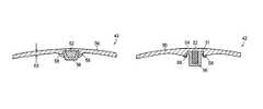
- FIG. 1Another embodiment of the present invention is a golf club head that includes a crown forming an upper surface of the golf club head, a sole forming a lower surface of the golf club head, and a hitting face disposed between the crown and the sole, wherein the hitting face further comprises a face insert welded around a perimeter thereof to the golf club head, and the face insert further comprises a plate-like face and an internal insert, wherein the plate-like face is made out of a material with a higher density than the material used to make the internal insert.
- the face insert in accordance with this embodimentmay have central zone with a first flexural stiffness and an intermediate zone with a second flexural stiffness, and wherein the first flexural stiffness is higher than the second flexural stiffness.
- FIG. 1is a front view of a striking face of the golf club head disclosed in the parent patent application;
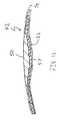
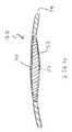
- FIGS. 1 a and 1 bare cross-sectional views of the striking face of FIG. 1 taken along lines 1 A- 1 A and 1 B- 1 B, respectively;
- FIG. 1 cis an alternate embodiment from the priority patent;
- FIG. 2is a front, exploded view of an alternate embodiment of the parent patent invention
- FIG. 3is a front plan view of an embodiment of a hitting face of the present invention.
- FIG. 3Ais a cross-sectional view of the hitting face of FIG. 3 taken along line 3 A- 3 A;
- FIG. 3Bis an exploded cross-sectional view of the hitting face of FIG. 3 ;
- FIG. 4is a cross-sectional view of an alternate embodiment of a hitting face of the present invention.
- FIG. 5is a cross-sectional view of another alternate embodiment of a hitting face of the present invention.
- FIG. 6is a cross-sectional view of another alternate embodiment of a hitting face of the present invention.
- FIG. 7is a cross-sectional view of another alternate embodiment of a hitting face of the present invention.
- FIG. 8is a cross-sectional view of another alternate embodiment of a hitting face of the present invention.
- FIG. 8Ais an exploded cross-sectional view of the hitting face of FIG. 8 ;
- FIG. 9is a cross-sectional view of another alternative embodiment of a hitting face of the present invention.
- FIG. 10is a cross-sectional view of another alternative embodiment of a hitting face of the present invention.
- FIG. 11is a cross-sectional view of another alternative embodiment of a hitting face of the present invention.
- FIG. 12is a cross-sectional view of another alternative embodiment of a hitting face of the present invention.
- FIG. 13is a cross-sectional view of another alternative embodiment of a hitting face of the present invention.
- FIG. 14is a cross-sectional view of another alternative embodiment of a hitting face of the present invention.
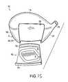
- FIG. 15is a front exploded view of an alternate embodiment of a club head
- FIG. 16is a perspective view of another alternate embodiment of a club head of the present invention.
- FIG. 17is a perspective view of another alternate embodiment of a club head of the present invention.
- FIG. 18 ais a top perspective view of another alternate embodiment of a club head of the present invention.
- FIG. 18 bis a bottom perspective view of the club head shown in FIG. 12 a;
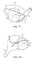
- FIG. 19 ais a top perspective view of another alternate embodiment of a club head of the present invention.
- FIG. 19 bis a bottom perspective view of the club head shown in FIG. 13 a;
- FIG. 20is a graph of inertance versus frequency for a conventional club head.
- FIG. 21is a graph of inertance versus frequency for the inventive club head discussed in priority case.
- COR or coefficient of restitutionis a measure of collision efficiency.
- CORis the ratio of the velocity of separation to the velocity of approach. In this model, therefore, COR was determined using the following formula: ( v club-post ⁇ v ball-post )/( v ball-pre ⁇ v club-pre ) where,
- CORin general, depends on the shape and material properties of the colliding bodies.
- a perfectly elastic impacthas a COR of one (1.0), indicating that no energy is lost, while a perfectly inelastic or perfectly plastic impact has a COR of zero (0.0), indicating that the colliding bodies did not separate after impact resulting in a maximum loss of energy. Consequently, high COR values are indicative of greater ball velocity and distance.
- the accuracy of the club and the club's large zone of uniform high initial velocityare produced by hitting face 2 , having central zone 4 , a surrounding intermediate zone 6 , and an optional perimeter zone 8 .
- the area of central zone 4comprises about 15% to about 60% of the total area of the hitting face 2 , and more preferably about 20% to about 50%.
- Central zone 4is comparatively rigid and intermediate zone 6 is relatively flexible so that upon ball impact, intermediate zone 6 of face 2 deforms to provide high ball velocity, while central zone 4 is substantially undeformed so that the ball flies on-target.
- intermediate zone 6allows central zone 4 to move into and out of a club head 10 as a unit.
- Surrounding intermediate zone 6may be located adjacent to central zone 4 , and optional perimeter zone 8 may be located adjacent to intermediate zone 6 .
- the headexhibits a coefficient of restitution greater than about 0.81.
- FSFlexural stiffness
- Eeach portion's average elastic modulus
- teach portion's average thickness
- the flexural stiffnessis a function of material and thickness
- the following techniquescan be used to achieve the substantial difference between the flexural stiffness of central zone 4 and intermediate zone 6 : 1) different materials can be used for each portion, 2) different thicknesses can be used for each portion, or 3) different materials and thickness can be used for each portion.
- the thickness of the central zoneis greater than the thickness of the intermediate zone and the material for both portions is the same.
- the above flexural stiffness relationshipscan be achieved by selecting a certain material with a particular elastic modulus and varying the thickness of the zones.
- the flexural stiffness relationshipscan be achieved by varying the materials of the zones with respect to one another so that the zones have different elastic moduli and the thickness is changed accordingly.
- the thickness of the zonescan be the same or different depending on the elastic modulus of the material of each zone. It is also possible to obtain the required flexural stiffness ratio through the use of structural ribs, reinforcing plates, and thickness parameters.
- the parent case application and the grandparent '007 patentdescribe in detail the preferred ranges of ratios of flexural stiffness between central zone 4 and intermediate zone 6 .
- central zone 4may be of generally uniform thickness and made from a stainless steel having a Young's Modulus of 30.0 ⁇ 10 6 lbs/in 2 .
- the adjacent intermediate zone 6has a continuously tapering thickness from the pace perimeter toward central zone 4 .
- the thickness of intermediate zone 6is defined to change linearly.
- Intermediate zone 6is made from a titanium alloy having a Young's Modulus of 16.5 ⁇ 10 6 lbs/in 2 .
- FIG. 1 cwhich corresponds to FIG.
- central zone 4may include ribs 4 a made of stainless steel having a Young's Modulus of 30.0 ⁇ 10 6 lbs/in 2 with a titanium alloy having a Young's Modulus of 16.5 ⁇ 10 6 lbs/in 2 in the interstitial spaces 4 b .
- Intermediate zone 6is made from the same titanium alloy. The flexural stiffness ratio between central zone 4 and intermediate zone 6 is calculated in detail in the '007 patent.
- Optional perimeter zone 8preferably increases in thickness compared to intermediate zone 6 to increase the flexural stiffness thereof.
- optional perimeter zone 8may increase in flexural stiffness compared to intermediate zone by forming perimeter zone 8 out of a different material than that of intermediate zone 6 .
- perimeter zone 8may be made of the same material as central zone 4 .
- perimeter zone 8may be made of an entirely different material than that of central zone 4 or intermediate zone 6 .
- Perimeter zone 8would then be attached to intermediate zone 6 , such as by welding.
- hitting face 2may comprise a face insert 42 , which is welded onto a cavity defined on the face.
- Hitting face 2may comprise a face insert 42 and face support 30 .
- hitting face 2is delineated from crown 14 , toe 18 , sole 22 and heel 32 by parting line 46 .
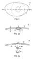
- Central zone 4is preferably disposed on the inner-cavity-facing surface of face insert 42 , and, as shown, has a generally elliptical shape. The elliptical central zone 4 is fully disclosed in the parent patent application.
- Central zone 4is preferably aligned in the direction of the low toe to high heel, so that a high COR zone can be established in the direction of high tow to low heel. This high COR zone advantageously coincides with the typical impact patterns created by golfers.
- the term “ellipse” or “elliptical”refers to non-circular shapes that have discernable major axis and minor axis, and include, but are not limited to, any quadrilateral shapes, geometrical ellipses, quadrilateral shapes with one or more rounded corner(s) and unsymmetrical elliptical shapes.
- the “major axis”is defined as the axis coinciding with the longest length that can be drawn through the non-circular shapes without intersecting the perimeter of the shapes at more than two locations, i.e., at the start and end points of said length.
- the “minor axis”is orthogonal to the major axis at or near its midpoint.
- the term “concentric”refers to shapes that substantially encircle or surround other shapes.
- Intermediate zone 6can be disposed partially on face insert 42 and partially on face support 30 .
- a transition zone 7 having variable thicknessis disposed between central zone 4 and intermediate zone 6 .
- the thickness of central zone 4is reduced to the lesser thickness of intermediate zone 6 within transition zone 7 . This reduces any local stress-strain caused by impacts with golf balls due to abrupt changes in thickness.
- Face support 30defines hole 48 , which is bordered by rim 49 .
- Face insert 42can be attached to face support 30 by welding at or around rim 49 .
- face insert 42is made by milling or stamping and forming.
- a malleable metal suitable for use as a hitting facesuch as titanium, titanium alloy, carbon steel, stainless steel, beryllium copper, and other forgeable metals, is heated and then hammered into the desired shape of the face cup.
- some appropriate metalsinclude but are not limited to titanium 6-4 alloy, titanium 15-3-3-3 alloy, titanium 20-4-1 alloy, and DAT 55 and DAT 55G, titanium alloys available from Diado Steel of Tokyo, Japan.
- the preferred forging processis die or billet forging, in which a pre-measured rod of forgeable metal is heated and placed between a die, which contains the desired shape of face insert 42 , and a hammer. The heated metal is then hammered into the desired shape.
- An advantage of forging face insert 42is that the thickness of the face can be as thin as about 0.060 inch (or about 1.5 mm) around the perimeter or edge thereof.
- FIGS. 3-8alternate embodiments of hitting face insert 42 are shown.
- the flexural stiffness of central zone 4is higher than the flexural stiffness of intermediate area 6 due to an internal insert 52 .
- internal insert 52may be a dense insert 52 made of a material of greater density than that of the material forming the remainder of face insert 42 , however, in an alternative embodiment, the internal insert 52 may be a lightweight insert 52 made of a material of less density than that of the material forming the remainder of the face insert 42 .
- FIG. 3AA cross-sectional view of a preferred embodiment of the present invention is shown in FIG. 3A , wherein face insert 42 includes a plate-like face 50 and an internal insert 52 .
- Plate-like face 50is preferably elliptical in shape with a slightly curved profile, although any shape may be used, such as polygonal, circular or irregular.
- plate-like face 50depends upon the overall size of golf club head 10 . However, in a preferred embodiment, plate-like face 50 measures between 80 and 100 mm along the long axis of the ellipse and between 35 and 60 mm along the short axis of the ellipse. More preferably, plate-like face 50 measures 90 mm along the long axis of the ellipse and 50 mm along the short axis. Plate-like face 50 may be of uniform or non-uniform thickness 53 . In one embodiment, thickness 53 ranges from 2-5 mm. Preferably, thickness 53 is 2.7 mm gradually tapering to a maximum thickness of 4.5 mm.
- Plate-like face 50may generally be placed at the front of the golf club and comes into contact with a golf ball, at a frontal external portion of the dense insert 52 .
- Plate-like face 50preferably includes a cavity 51 , shown in the exploded view of FIG. 3B , formed on the surface 55 that faces the inner cavity of golf club head 10 . Further, in the vicinity of cavity 51 , plate-like face 50 preferably increases in thickness, so as to combine the effects of a thickened central zone as described above with the effects of the different material that could be used for dense insert 52 .
- cavity 51is circular in shape, although the shape of cavity 51 is preferably chosen to correspond to the cross-sectional shape of dense insert 52 .
- cavity 51may be made of any size sufficient to accommodate dense insert 52 , in one embodiment, cavity 51 has an interior width of approximately 14 mm and a depth of approximately 2 mm.
- plate-like face 50is preferably forged, although stamping and casting are also suitable manufacturing techniques.
- Plate-like face 50may be made of any material discussed herein that is suitable for forming hitting face 2 , such as titanium, titanium alloy, carbon steel, stainless steel, beryllium copper.
- the more preferred metalis titanium 6-4 alloy, as described above.
- Dense insert 52 shown in the current embodimentmay be of a conical frusta shape that is relatively small in cross-sectional surface area compared to plate-like face 50 .
- Dense insert 52may take on any shape that is convenient for manufacturing, for example a cylinder or a circular, elliptical or quadrilateral disk.
- Dense insert 52is made of a material of greater density than that of plate-like face 50 , preferably tungsten or stainless steel, although any material of greater density than plate-like face 50 is appropriate for use in the present invention, including copper, nickel, and bronze.
- internal insert 52may be made out of a lightweight material to create a lightweight insert that has a lower density than that of the plate-like face 50 .
- lightweight insert 52may generally be made out of composite materials such as carbon fiber reinforced plastic, fiber reinforced plastic, glassed reinforced plastic, or even plywood, so long as the material provides a lightweight weight savings characteristic all without departing from the scope and content of the present invention.
- dense insert 52is preferably small compared to the size of plate-like face 50 , however dense insert 52 may constitute a majority of the volume of the face insert 42 without departing from the scope and content of the entire invention
- dense insert 52is approximately 10 mm in diameter at its widest point and approximately 7 mm in height. As such, dense insert 52 protrudes from surface 55 of plate-like face 50 , as dense insert 52 is of a greater height than the depth of cavity 51 .
- the size of dense insert 52may be varied so as to control the effective size of central zone 4 .
- dense insert 52may be directly or indirectly affixed to plate-like face 50 .
- dense insert 52is contained within a cap 56 made of the same material as that used to make plate-like face 50 so that cap 56 may be readily welded to plate-like face 50 .
- dense insert 52may be affixed to an interior surface of cap 56 , adhered to at least one interior surface of cap 56 , or simply rest within cap 56 .
- cap 56is a conical frusta having an interior cavity shaped so that dense insert 52 fits tightly within cap 56 .
- Cap 56may be made using any method known in the art, such as casting, stamping or forging.
- dense insert 52is indirectly fixedly attached to plate-like face 50 , in that dense insert 52 is contained within cap 56 which is joined to plate-like face 50 by a weld bead 58 so that dense insert 52 is not dislodged from its position during the repeated impacts of hitting face 2 with golf balls.
- at least a portion of the combination of dense insert 52 and cap 56may be secured within cavity 51 using an adhesive, for example hot melt adhesives, epoxy adhesives, polyurethane adhesives, sealants, thermoset adhesives, UV curing adhesives, silicon adhesives, acrylic and cyanoacrylic adhesives.
- dense insert 52is a circular disk that is adhered directly to the inner cavity-facing surface 55 of plate-like face 50 .
- dense insert 52may also be welded to the surface of plate-like face 50 .
- plate-like face 50includes a cavity 51 into which dense insert 52 in the shape of a circular disk in inserted.
- Dense insert 52may or may not be affixed to the surface of cavity 51 , such as with an adhesive.
- a flange portion 54extends over dense insert 52 to hold dense insert 52 within cavity 51 , i.e., to prevent dense insert 52 from being ejected from cavity 51 during repeated impacts with golf balls.
- Flange portion 54may be a piece of material welded to plate-like face 50 . Alternatively, flange portion 54 may be formed during manufacturing of plate-like face 50 .
- Face insert 42is preferably milled and/or stamped.
- cavity 51is formed in a thickened central zone of plate-like face 50 .
- Cavity 51is formed to a height that is slightly higher than the height of dense insert 52 .
- Dense insert 52is then positioned within cavity 51 and preferably adhered to an inner surface of cavity 51 .
- the surface of plate-like face 50is then forcibly struck or hammered to deform the portion cavity 51 protruding over dense insert 52 , thereby forming flange portion 54 .
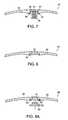
- FIG. 6another alternate embodiment of multiple-material face insert 42 is shown.
- This embodimentincludes a plate-like face 50 similar to the plate-like faces of earlier-described embodiments.
- plate-like faceincludes a thin-walled cup-like protrusion 60 extending outward from the inner cavity-facing surface 55 of plate-like face 50 .
- Cup-like protrusion 60is shown as a frusta, although it may have any shape, such as a hollow cylinder, three-dimensional polygon, or an irregular shape.
- Dense insert 52similar to the inserts described above, is sized and dimensioned to fit tightly within cup-like protrusion 60 .
- Dense insert 52may be affixed to the interior of cup-like protrusion 60 using, for example, an adhesive.
- dense insert 52is held within cup-like protrusion 60 by flange portion 54 , similar to earlier-discussed flange portions. In this embodiment, however, if the stamping technique is used to form flange portion 54 , the excess material comes from the excess height of cup-like protrusion 60 .
- plate-like face 50is similar to the plate-like face described above with respect to the preferred embodiment.
- cap 56is a hollow cylinder having an outer diameter that is less than the diameter of cavity 51 .
- Dense insert 52is a cylindrical plug that fits tightly within cap 56 , preferably affixed therewithin.
- Cap 56includes a brim 64 that is sized and dimensioned to fit snugly within cavity 51 . As such, a small amount of clearance exists between the outer diameter of cap 56 and the edge of cavity 51 .
- Weld bead 58is formed around the edge of cavity 51 and the edge of brim 64 to attach cap 56 to plate-like face 50 .
- This geometry of cap 56increases the surface area to which weld bead 58 may affix, thereby increases the strength of the joint. As such, the usable life of hitting face 2 increases, as the stronger joint is less likely to suffer failure and eject dense insert 52 into the inner cavity of golf club head 10 .
- face insert 42includes plate-like face 50 and a dense insert 52 .
- a void 61is formed at or near the center of plate-like face 50 extending entirely through the thickness thereof.
- Dense insert 52is preferably configured such that at least a portion thereof is fitted into void 61 while a brim portion 63 thereof rests upon or is affixed to a lip or shelf 66 formed in void 61 .
- a flange portion 54similar to those flange portions described above, holds dense insert 52 securely in place.
- dense insert 52is visible from the exterior-facing surface 65 of plate-like face 50 .
- the exterior-facing surface of dense insert 52is shown as being substantially flush with surface 65 , this need not be the case and a gap may exist between the edges of void 61 such that dense insert 52 is still visible.
- FIG. 9 of the accompanying drawingsshows cross-sectional view of a further alternative embodiment of the present invention wherein the internal insert 52 may be a lightweight insert 52 that comprises of a significant portion of the face insert 42 .
- the relationship created by the face insert 42 in FIG. 9may be said to have a lightweight insert 52 with a volume that is significantly greater than the volume of the plate-like face 50 .
- the plate-like face 50may generally be made out of material with a higher density such as titanium for its durability characteristics while the lightweight insert 52 may generally be made out of a lower density material such as a carbon fiber composite for weight saving benefits.
- Plate-like face 50may generally need to be comprised out of a metallic material that has high strength and durability characteristics because it is the portion of the face insert 42 that comes into contact with a golf ball.
- the lightweight insert 52may need to be comprised out of a lightweight composite material for its weight saving characteristics.
- Plate-like face 50made out of a material with a higher density, may have a face density of greater than about 2.5 grams/cubic centimeter (g/cc), more preferably greater than about 2.75 g/cc, and most preferably greater than about 3.0 g/cc.
- Lightweight insert 52made out of a material with a lower density, may have an insert density of less than about 2.0 g/cc, more preferably less than about 1.9 g/cc, most preferably less than about 1.8 g/cc.
- the ratio of the density of the plate-like face 50 relative to the lightweight insert 52may generally be greater than 1.25, more preferably greater than about 1.45, and most preferably greater than about 1.67. This ratio of the density between the plate-like face 50 and the lightweight insert 52 is significant to the performance of the face insert 42 because it determines the amount of weight savings that can be achieved based on the two separate components.
- plate-like face 50may have a relatively thin metallic layer that has a thickness that is less than about 0.01 inches (or about 0.254 mm), more preferably less than about 0.005 inches (or about 0.127 mm), and most preferably less than about 0.003 inches (or about 0.0762 mm).
- the thickness of the lightweight insert 52 matching the thicknesses of the plate-like face 50may generally be greater than about 0.05 inches (or about 1.27 mm), more preferably greater than about 0.055 inches (1.397 mm), and most is preferably greater than about 0.057 inches (1.4478 mm).
- the face insert 42By having a significant amount of the face insert 42 be made out of a lightweight material, significant weight savings could be achieved from a conventional face insert 42 that is made purely out of a material such as titanium, titanium alloy, carbon steel, stainless steel or even beryllium copper. Comparatively, the total amount of weight savings achievable by having the face insert 42 be made out of the lightweight material may generally be greater than about 11 grams, more preferably greater than about 24 grams, and most preferably greater than about 32 grams.
- the weight saved by the lightweight insert 52is advantageous to the design of a golf club because it could be strategically shifted to alternative locations within the golf club head that increase the performance characteristics such as the moment of inertia of the golf club head.
- the cross-sectional view of the face insert 42 shown in FIG. 9also shows the lightweight insert 52 having a variable thickness to help achieve the variable flexural stiffness previously discussed as being a desirable feature. More specifically, having the central zone 6 be of a different thickness than the intermediate zone 6 allows the central zone 4 to move into and out of the club head as a unit, creating a higher COR as mentioned above. However, it should be noted that the lightweight insert 52 could have a uniform thickness in congruence with the shape of the plate-like face 50 as well without departing from the scope and content of the present invention.
- FIG. 10 of the accompanying drawingsshows a cross-sectional view of a further alternative embodiment of the present invention wherein the plate-like face 50 may also have a variable thickness similar to the variable thickness of the lightweight insert 52 .
- the face insert 42 shown by FIG. 10may be preferred in situations wherein the durability of the entire face insert 42 needs to be increased. Although not a direct correlation, the strength of the material has a lot to do with the weight and density of the material itself. Hence it can be seen that in certain situations wherein the durability of the face insert 42 needs to be increased, it may be desirable to increase the thickness of the plate-like face 50 .
- the cross-sectional view of the face insert 42 in accordance with the further alternative embodiment shown in FIG. 10also shows a flange 54 around the perimeter of the of the face insert 42 .
- the flange 54 shown in FIG. 10similar to the flange 54 discussed earlier, maybe be used to maintain the relative position of the lightweight insert 52 relative to the plate-like face 50 .
- FIG. 11 of the accompanying drawingsshows a cross-sectional view of a further alternative embodiment of the present invention wherein the face insert 42 is further comprised of an additional rear layer 57 that's made from a heavier and more durable metallic material similar to that of the plate-like face 50 .
- the rear layer 57may serve the same purpose as the cap 56 in helping retain the rear layer together with the plate-like face 50 , it is also capable of providing strength and durability to the face insert 42 itself. Because the face insert 42 deflects and deforms when it impacts a golf ball, the location that is subjected to the most deformation is at the rear surface of the face insert 42 .
- utilizing a heavier more durable material for the rear layer 57provides structural rigidity to the face insert 42 at one of the highest stress level locations.
- the material used for the rear layer 57may be the same as the material used for the plate-like face 50 , including but not limited to common high strength metallic materials such as titanium or any other of the materials mentioned above that's suitable for plate-like face 50 .
- rear layer 57need not be made out of the same material as the plate-like face 50 , but could be made out of a material that is completely independent of the plate-like face 50 so long as it offers sufficient structural support to endure the stresses of impact with a golf ball without departing from the scope and content of the present invention.
- the rear layer 57may also be a relatively thin layer of coating like the plate-like face 50 having a thickness that is less than about 0.01 inches (or about 0.254 mm), more preferably less than about 0.005 inches (or about 0.127 mm), and most preferably less than about 0.003 inches (or about 0.0762 mm)
- FIG. 12 of the accompanying drawingshows a cross-sectional view of a further alternative embodiment of the present invention wherein the lightweight insert 52 is completely encompassed by the plate-like face 50 , the flange 54 , and the rear layer 57 .
- the lightweight insert 52is coated by a heavier and more durable metallic coating without departing from the scope and content of the present invention. Having the rear layer 57 completely coated or encompassed by the heavier and more durable metallic material may be preferable in certain situations, as it combines the benefits of all of the features into one convenient embodiment of the present invention.
- the components used to encompass the lightweight insert 52such as the plate-like face 50 , the flange 54 , and the rear layer 57 may be separately identified in their individual capacity in specifications, these components can all be formed uniformly via a coating process for ease of manufacturing without departing from the scope and content of the present invention.
- FIG. 13 of the accompanying drawingsshows a cross-sectional view of a further alternative embodiment of the present invention wherein the plate-like face 50 may have an increased thickness to increase the durability of the portion of the face insert 42 that comes into repeated impact with a golf ball. Similar to what has already been discussed above in FIG. 10 , the thickened plate-like face 50 portion in combination with the rear layer 57 and the flange 54 allows this embodiment to have an extremely durable face insert 42 , while still taking advantage of the weight savings achievable by the lightweight composite material used for the lightweight insert 52 .
- FIG. 14 of the accompanying drawingsshows a cross-sectional view of an even further alternative embodiment of the present invention wherein the lightweight insert 52 may only occupy a central portion of the face insert 42 .
- having a lightweight insert 52 behind the impact portion of the face insert 42may help improve the flexural stiffness of the face insert 42 at areas where the golfer may generally use to hit a golf ball.
- Having a lightweight insert 52 that is light in weight behind the impact portion of the face insert 42may achieve both the goal of improving the flexural stiffness of the face insert 42 , as well as reducing unnecessary weight from the face insert 42 simultaneously.
- Inventive Club Wis a hollow metal wood club head made generally in accordance with the embodiment shown in FIG. 7 .
- Club Wincludes a face insert made of a plate of titanium alloy having a tungsten insert welded to the inner-cavity-facing surface thereof at or near the geometric center of the plate.
- the thickness of Club Wvaries in that the central zone of the face insert is thicker than the perimeter thereof.
- Club Whas a COR measured to be 0.812.
- a standard King Cobra® SZ 440 club headis also a hollow metal wood club head.
- the SZ 440 club headhas a hitting face having variable thickness. Similar to Club W, the SZ 440 club head is thicker near the geometric center of the hitting face and thinner toward the perimeter thereof. However, the thickness variations of the SZ 440 club head hitting face are manufactured integrally with the hitting face, i.e., the hitting face includes a single plate of material that is machined to remove a portion of the material only around the perimeter of the plate.
- the SZ 440 club headhas a COR of 0.814, approximately equal to that of Club W.
- the characteristic time of the pendulum with Club Wis greater than that of the SZ 440 club face at all tested points.
- the flexibility of Club Wis greater than that of the SZ 440 club face, even though the COR value is approximately the same for both club heads.
- the thickness of intermediate zone 6 or optional perimeter portion 8 on hitting face 2can be thinly manufactured by removing the weld lines from the hitting face to the crown and sole of the club head.
- An alternate method for improving the performance of hitting face 2is to remove weld lines and joints of face insert 42 to another surface of club head 10 .
- a weld line or jointis an area of discontinuity, where even if two pieces of the same material are joined, the structural properties of the pieces in the vicinity of the joint are altered. Removing weld lines to the crown or the sole of a club head allows the thickness of the hitting face to be controlled more precisely and allows for a thinner overall hitting face.
- the jointscan also be used to alter the properties of the hitting face.
- the face insertmay include one or more side walls, wherein the side walls may form part of the crown and/or part of the sole.
- face insert 42comprises central zone 4 , transition zone 7 , a portion of intermediate zone 6 , partial crown portion 54 and partial sole portion 56 .
- Club head 10correspondingly defines cavity 58 sized and dimensioned to receive face insert 42 .
- Face insert 42is preferably welded to club head 10 .
- Face insert 42 together with face support 30forms hitting face 2 .
- intermediate zone 6designated as 6 1 and 6 2 , can be disposed partially on face insert 42 and partially on face support 30 .
- central zone 4 of hitting face 2is formed of a face insert 42 .
- Face insert 42is preferably welded to club head 10 along weld line 20 .
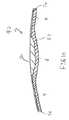
- Face insert 42includes a polygonal or elliptical main plate 34 and a sidewall or wing 70 that extends into and forms a part of crown 14 .
- an upper portion 71 of weld line 20is removed to crown 14 .
- the stress line created by weld line 20is removed from hitting face 2 , the probability of failure along upper portion 21 due to repeated impact with golf balls is reduced.
- Face insert 42is preferably made from the same material as the rest of club head 10 , such as titanium, a titanium alloy, steel, or any other material suitable for use as a club head. Face insert 42 is preferably the same thickness as the rest of club head 10 , although face insert 42 may be made thicker or thinner in order to affect the flexural stiffness thereof.
- face insert 42may vary. As stated above, preferably, face insert 42 is a modified oval U-cup or L-cup, but it may also be other shapes, such as rectangular, elliptical or circular. Face insert 42 preferably forms nearly the entire surface area of hitting face 2 . However, face insert 42 may form a much smaller portion of hitting face. Also, wing 70 may extend into and form a part of sole 22 , as shown in FIG. 17 , by simply inverting the configuration of face insert 42 . In this case, the affected weld line is lower weld line 73 .
- face insert 42can also be affected by the method chosen to form face insert 42 .
- face insert 42is preferably stamped from sheet metal after the metal has been cold rolled or cold worked in order to align the crystal grains of the metal. Stamping metal in this fashion produces a stronger hitting face than other manufacturing techniques. Further, face insert 42 is then positioned within hitting face 2 so that the grain flow pattern of face insert 42 runs in a sole-to-crown direction. Alternatively, the grain flow pattern of face insert 42 may run in a heel-to-toe direction or in a diagonal direction. Other methods known in the art may also be used to manufacture face insert 42 , such as forging and casting.
- FIGS. 18 a and 18 bshow another embodiment of club head 10 similar to the embodiment shown in FIG. 16 .
- face insert 42includes a main plate 34 , an upper sidewall or wing 70 that extends into and forms part of crown 14 as well as a lower wing 72 that extends into and forms part of sole 22 .
- upper weld line 71 and lower weld line 73are removed to crown 14 and sole 22 , respectively, so as to reduce the potential for failure thereof. All other aspects of face insert 42 are as described above with respect to FIG. 16 .
- FIGS. 19 a and 19 bshow yet another embodiment of club head 10 similar to the embodiment shown in FIG. 16 .
- face insert 42includes an upper sidewall or wing 70 that extends into and forms part of crown 14 , a lower sidewall or wing 72 that extends into and forms part of sole 22 , a heel extension 74 , and a toe extension 75 .
- Upper wing 70 and lower wing 72are as described above with respect to FIGS. 16 , 18 a , and 18 b .
- Heel extension 74 and toe extension 75are extensions of the main plate of face insert 42 along the horizontal axis 76 thereof at or near the center of the vertical axis 78 thereof. This alteration of the geometry of face insert increases the deflection capabilities of face insert 42 along horizontal axis 76 while vertical axis 78 has a different, lesser deflection capability.
- Face insert 42is preferably of a size and general shape as described above with respect to the embodiment shown in FIGS. 16 , 18 a and 18 b , i.e., a polygonal or elliptical main plate that fauns much of the surface area of hitting face 2 .
- Upper wing 70 and lower wing 73are preferably generally elliptical or polygonal, although other shapes are contemplated by the present invention.
- heel extension 74 and toe extension 75are preferably semi-elliptical in shape, although other shapes such as semi-circular are contemplated by the present invention.
- face insert 42is a central oval having a long axis along horizontal axis 76 of hitting face 2 and generally rectangular extensions stretching along vertical axis 78 of hitting face 2 .
- heel extension 74 and toe extension 75may be eliminated.
- upper wing 70 and lower wing 73may be eliminated.
- face insert 42may incorporate an internal insert 52 as shown in any of the embodiments shown in FIGS. 3-8 for increased performance effects.
- Face insert 42may also contain central zone 4 and intermediate zone 6 , where the flexural stiffness of central zone 4 is higher then the flexural stiffness of intermediate zone 6 , as described above and as described in the parent application and in the grandparent '007 patent. Additionally, central zone 4 may also include an internal insert 52 as described above.
- Hitting face 2is preferably milled or stamped and milled.
- the body of club 10is preferably cast.
- the inner cavity of club head 10may be empty, or alternatively may be filled with foam or other low specific gravity material. It is preferred that the inner cavity has a volume greater than 250 cubic centimeters, and more preferably greater than 275 cubic centimeters, and most preferably 350 cubic centimeters or more.
- the mass of the inventive club headis greater than 150 grams but less than 220 grams. Further part and manufacturing details and additional test results regarding the COR values of inventive club heads are discussed in detail in the parent case.
- inertanceis a frequency response. More specifically, inertance reflects the stiffness of a structure, in this instance the club face, at various frequencies of vibration.
- the units of inertanceare acceleration units over force units.
- a preferred first resonant frequency for the inventive club face described hereinis located where inertance is maximized.
- FIG. 20a graph of inertance versus frequency for a conventional club head is shown.
- the conventional club headis a Callaway Great Big Bertha War Bird with an eight degree loft.
- the point I 1 at a frequency of 3330 Hertzrepresents the first primary resonant frequency which occurs at the first primary maxima inertance for the inertance function I.
- a maxima which does not represent a primary resonant natural frequency of the faceis also present in FIG. 20 at a frequency of 2572 Hertz, which is designated as point 12 .
- These secondary maxima 12are characterized by inertance transitions of a magnitude of less than 10 decibels.
- the contact durationis the time interval during which the ball is in contact with the club face.
- the contact duration for a typical driver impactis about 500 microseconds.
- the preferred primary resonant frequency of vibration for the conventional club headis between about 1000 and 3000 Hertz. The closer the COR is to the lower limit, the higher the COR and thus the higher the rebound ball velocity. More preferably, the first primary resonant frequency is less than 2900.
- FIG. 21illustrates the inertance function of the inventive club head described and claimed in priority U.S. Pat. No. 6,605,007 (“the '007 club”).
- the first primary resonant frequency of vibration for the club headis at 2632 Hertz, and the COR of the '007 club was measured to be 0.824.
- the COR of the '007 clubwas measured to be 0.824.
- the COR of the '007 clubis greater than the conventional club of FIG. 20 , and therefore will provide greater ball rebound velocity.
- the overall flexural stiffness of a club head and the distribution of the flexural stiffness across the face of the club headimpact the resonant frequency of a club head.
- the swing speedwill determine if the club and/or a golf ball vibrates at the resonant frequency upon impact.
- a club designermay alter the resonant frequency of the club head to coordinate with the resonant frequency of a particular golf ball so as to maximize the distance traveled by the ball when struck at a certain swing speed.
- the clubcan be designed to resonate upon striking a particular golf ball at the golfer's average swing speed.
- the resonance frequency of the clubis 0-20% greater than the resonant frequency of the ball. More preferably, the resonance frequency of the club is 0-10% greater than the resonant frequency of the ball.
- the face and/or individual zonescan have thickness variations in a step-wise or continuous fashion.
- Other modificationsinclude a perimeter zone that has a thickness that is greater than or less than the adjacent, intermediate zone.
- the shapes of the central, intermediate, and perimeter zonesare not limited to those disclosed herein.
Landscapes
- General Health & Medical Sciences (AREA)
- Health & Medical Sciences (AREA)
- Physical Education & Sports Medicine (AREA)
- Life Sciences & Earth Sciences (AREA)
- Physics & Mathematics (AREA)
- Analytical Chemistry (AREA)
- Acoustics & Sound (AREA)
- Chemical & Material Sciences (AREA)
- Biophysics (AREA)
- Biochemistry (AREA)
- General Physics & Mathematics (AREA)
- Immunology (AREA)
- Pathology (AREA)
- Engineering & Computer Science (AREA)
- Wood Science & Technology (AREA)
- Golf Clubs (AREA)
Abstract
Description
(vclub-post−vball-post)/(vball-pre−vclub-pre)
where,
- vclub-postrepresents the velocity of the club after impact;
- vball-postrepresents the velocity of the ball after impact;
- vclub-prerepresents the velocity of the club before impact (a value of zero for USGA COR conditions); and
- vball-prerepresents the velocity of the ball before impact.
| TABLE 1 |
| Nine Point Pendulum Test Results SZ 440, Club W |
| PEN | PEN | PEN | PEN | PEN | PEN | ||||
| PEN | PEN | PEN | High | High | High | Low | Low | Low | |
| Club Model | Center | Toe | Heel | Center | Toe | Heel | Center | Toe | Heel |
| Comparative | 235 | 238 | 235 | 229 | 244 | 240 | 227 | 226 | 232 |
| SZ 440 | |||||||||
| Inventive Club W | 251 | 269 | 250 | 251 | 266 | 263 | 268 | 255 | 235 |
1/(2*contact duration)<I1<3/(2*contact duration)
Claims (20)
Priority Applications (1)
| Application Number | Priority Date | Filing Date | Title |
|---|---|---|---|
| US12/760,740US8342982B2 (en) | 2003-05-01 | 2010-04-15 | Metal wood club with improved hitting face |
Applications Claiming Priority (6)
| Application Number | Priority Date | Filing Date | Title |
|---|---|---|---|
| US10/428,061US7029403B2 (en) | 2000-04-18 | 2003-05-01 | Metal wood club with improved hitting face |
| US10/911,341US7207898B2 (en) | 2000-04-18 | 2004-08-04 | Metal wood club with improved hitting face |
| US11/687,137US7361099B2 (en) | 2000-04-18 | 2007-03-16 | Metal wood club with improved hitting face |
| US12/059,137US7520819B2 (en) | 2000-04-18 | 2008-03-31 | Metal wood club with improved hitting face |
| US12/404,369US7850543B2 (en) | 2000-04-18 | 2009-03-16 | Metal wood club with improved hitting face |
| US12/760,740US8342982B2 (en) | 2003-05-01 | 2010-04-15 | Metal wood club with improved hitting face |
Related Parent Applications (1)
| Application Number | Title | Priority Date | Filing Date |
|---|---|---|---|
| US12/404,369Continuation-In-PartUS7850543B2 (en) | 2000-04-18 | 2009-03-16 | Metal wood club with improved hitting face |
Publications (2)
| Publication Number | Publication Date |
|---|---|
| US20100197425A1 US20100197425A1 (en) | 2010-08-05 |
| US8342982B2true US8342982B2 (en) | 2013-01-01 |
Family
ID=42398173
Family Applications (1)
| Application Number | Title | Priority Date | Filing Date |
|---|---|---|---|
| US12/760,740Expired - Fee RelatedUS8342982B2 (en) | 2003-05-01 | 2010-04-15 | Metal wood club with improved hitting face |
Country Status (1)
| Country | Link |
|---|---|
| US (1) | US8342982B2 (en) |
Cited By (11)
| Publication number | Priority date | Publication date | Assignee | Title |
|---|---|---|---|---|
| US20120214611A1 (en)* | 2010-12-20 | 2012-08-23 | Myrhum Mark C | Striking face of a golf club head |
| US20180353817A1 (en)* | 2013-08-20 | 2018-12-13 | Karsten Manufacturing Corporation | Golf club head with polymeric face |
| US10695620B2 (en) | 2013-11-05 | 2020-06-30 | Karsten Manufacturing Corporation | Club heads with bounded face to body yield strength ratio and related methods |
| US11446553B2 (en) | 2013-11-05 | 2022-09-20 | Karsten Manufacturing Corporation | Club heads with bounded face to body yield strength ratio and related methods |
| US20230018341A1 (en)* | 2016-07-26 | 2023-01-19 | Acushnet Company | Golf club having a damping element for ball speed control |
| US11771962B2 (en) | 2020-08-21 | 2023-10-03 | Wilson Sporting Goods Co. | Faceplate of a golf club head |
| US11969631B2 (en) | 2014-05-15 | 2024-04-30 | Karsten Manufacturing Corporation | Club heads having reinforced club head faces and related methods |
| US12048866B2 (en) | 2014-05-15 | 2024-07-30 | Karsten Manufacturing Corporation | Club heads having reinforced club head faces and related methods |
| US12214265B1 (en) | 2020-12-04 | 2025-02-04 | Cobra Golf Incorporated | Golf club face plate having correlated characteristic time measurement map |
| US12233318B2 (en) | 2020-12-29 | 2025-02-25 | Taylor Made Golf Company, Inc. | Golf club heads |
| US12377329B2 (en) | 2016-07-26 | 2025-08-05 | Acushnet Company | Golf club having a damping element for ball speed control |
Families Citing this family (8)
| Publication number | Priority date | Publication date | Assignee | Title |
|---|---|---|---|---|
| US8834289B2 (en)* | 2012-09-14 | 2014-09-16 | Acushnet Company | Golf club head with flexure |
| US10004955B2 (en)* | 2014-05-15 | 2018-06-26 | Karsten Manufacturing Corporation | Golf club head with open crown and related methods |
| US10918919B2 (en)* | 2014-05-15 | 2021-02-16 | Karsten Manufacturing Corporation | Club heads having reinforced club head faces and related methods |
| US11618306B2 (en) | 2016-10-27 | 2023-04-04 | Nicholas J. Singer | Skeleton for truck bed and convertible top |
| US10625126B2 (en) | 2016-12-29 | 2020-04-21 | Taylor Made Golf Company, Inc. | Golf club head |
| US11559727B2 (en) | 2016-12-29 | 2023-01-24 | Taylor Made Golf Company, Inc. | Golf club head |
| US10543409B2 (en)* | 2016-12-29 | 2020-01-28 | Taylor Made Golf Company, Inc. | Golf club head |
| US20220072393A1 (en)* | 2017-01-10 | 2022-03-10 | Parsons Xtreme Golf, LLC | Golf club heads and methods to manufacture golf club heads |
Citations (185)
| Publication number | Priority date | Publication date | Assignee | Title |
|---|---|---|---|---|
| US1318325A (en) | 1919-01-03 | 1919-10-07 | Martin D Klin | Golf-club. |
| US1319233A (en) | 1919-10-21 | George w | ||
| US1467435A (en) | 1921-01-31 | 1923-09-11 | Kinnear William | Golf club |
| US1525352A (en) | 1924-02-27 | 1925-02-03 | Aitken James Abram Garfield | Golf-club |
| US1543691A (en) | 1922-06-10 | 1925-06-30 | William N Beat | Golf club |
| US1582836A (en) | 1925-07-17 | 1926-04-27 | Thos E Wilson & Co | Metallic golf-club head |
| US1589363A (en) | 1925-04-18 | 1926-06-22 | Cuthbert S Butchart | Golf club |
| US1595589A (en) | 1926-03-22 | 1926-08-10 | Ralph G Tyler | Golf-club head |
| US1605551A (en) | 1923-08-03 | 1926-11-02 | Crawford Mcgregor & Canby Co | Insert for golf clubs |
| US1699874A (en) | 1927-12-09 | 1929-01-22 | R H Buhrke Co | Golf-club construction |
| US1704165A (en) | 1927-12-09 | 1929-03-05 | R H Buhrke Co | Golf-club construction |
| US1704119A (en) | 1927-12-09 | 1929-03-05 | R H Buhrke Co | Golf-club construction |
| US1720867A (en) | 1928-04-30 | 1929-07-16 | Webster George Greig | Golf-club construction |
| US2034936A (en) | 1931-07-15 | 1936-03-24 | George E Barnhart | Golf club |
| US2087685A (en) | 1935-02-16 | 1937-07-20 | William A Blair | Golf club |
| US3567228A (en) | 1968-10-09 | 1971-03-02 | John Nord Lynn | High energy golf club |
| US3571900A (en) | 1969-12-08 | 1971-03-23 | Shakespeare Co | Method of molding a golf club head |
| US3625518A (en) | 1969-05-23 | 1971-12-07 | Karsten Solheim | Golf club head with complex curvature for the sole and/or the striking face |
| US3659855A (en) | 1967-09-15 | 1972-05-02 | Shakespeare Co | Golf club head and novel method of producing same |
| US3863932A (en) | 1973-05-21 | 1975-02-04 | Wilson Sporting Goods | Weighted wood golf club |
| US3985363A (en) | 1973-08-13 | 1976-10-12 | Acushnet Company | Golf club wood |
| US4023802A (en) | 1974-10-02 | 1977-05-17 | Acushnet Company | Golf club wood |
| US4193601A (en) | 1978-03-20 | 1980-03-18 | Acushnet Company | Separate component construction wood type golf club |
| US4213613A (en) | 1977-12-29 | 1980-07-22 | Nygren Gordon W | Golf club head with center of gravity near its striking face |
| US4214754A (en) | 1978-01-25 | 1980-07-29 | Pro-Patterns Inc. | Metal golf driver and method of making same |
| USD267965S (en) | 1979-07-06 | 1983-02-15 | Maruman Golf Kabushiki Kaisha | Iron club head |
| US4429879A (en) | 1982-04-05 | 1984-02-07 | Schmidt Glenn H | Sole plate internal suspension in metal shells to form metal woods |
| US4432549A (en) | 1978-01-25 | 1984-02-21 | Pro-Pattern, Inc. | Metal golf driver |
| US4449707A (en) | 1982-05-22 | 1984-05-22 | Mizuno Corporation | Golf club head of carbon fiber reinforced plastic |
| US4451041A (en) | 1982-02-05 | 1984-05-29 | Mizuno Corporation | Golf club head and a method for manufacturing the same |
| US4451042A (en) | 1982-04-07 | 1984-05-29 | Mizuno Corporation | Golf club head of carbon fiber reinforced plastic |
| US4465221A (en) | 1982-09-28 | 1984-08-14 | Schmidt Glenn H | Method of sustaining metallic golf club head sole plate profile by confined brazing or welding |
| US4471961A (en) | 1982-09-15 | 1984-09-18 | Pepsico, Inc. | Golf club with bulge radius and increased moment of inertia about an inclined axis |
| US4489945A (en) | 1981-07-04 | 1984-12-25 | Muruman Golf Kabushiki Kaisha | All-metallic golf club head |
| US4511145A (en) | 1983-07-18 | 1985-04-16 | Schmidt Glenn H | Reinforced hollow metal golf club head |
| US4762324A (en) | 1987-01-27 | 1988-08-09 | Anderson Donald A | Gold club |
| US4792140A (en) | 1983-03-28 | 1988-12-20 | Sumitomo Rubber Industries, Ltd. | Iron type golf club head |
| US4826172A (en) | 1987-03-12 | 1989-05-02 | Antonious A J | Golf club head |
| US4842243A (en) | 1988-01-19 | 1989-06-27 | Lie Angle Solutions, Inc. | Method and apparatus for molding golf club heads |
| US4913438A (en) | 1987-01-27 | 1990-04-03 | Anderson Donald A | Golf club |
| US4915385A (en) | 1987-01-27 | 1990-04-10 | Anderson Donald A | Golf club |
| US4915386A (en) | 1988-10-25 | 1990-04-10 | Antonious A J | Perimeter weighted iron type golf club head with centrally located complementary weight |
| US4919431A (en) | 1987-03-12 | 1990-04-24 | Antonious A J | Golf club head |
| US4919430A (en) | 1987-03-12 | 1990-04-24 | Antonious A J | Golf club head |
| US4921252A (en) | 1987-09-14 | 1990-05-01 | Antonious A J | Iron type golf club head with integral sighting and alignment means |
| US4928965A (en) | 1984-07-10 | 1990-05-29 | Sumitomo Rubber Industries, Ltd. | Golf club and method of designing same |
| US4930781A (en) | 1988-08-17 | 1990-06-05 | Allen Dillis V | Constant resonant frequency golf club head |
| US4932658A (en) | 1987-03-12 | 1990-06-12 | Antonious A J | Golf club head |
| US4955610A (en) | 1989-02-27 | 1990-09-11 | Creighton William W | Driving iron golf club head |
| USD312858S (en) | 1988-04-14 | 1990-12-11 | Donald J. C. Sun | Putter head |
| US5000454A (en) | 1988-08-31 | 1991-03-19 | Maruman Golf Kabushiki Kaisha | Golf club head |
| US5024437A (en) | 1989-06-12 | 1991-06-18 | Gear Fit Golf, Inc. | Golf club head |
| US5028049A (en) | 1989-10-30 | 1991-07-02 | Mckeighen James F | Golf club head |
| US5046733A (en) | 1989-12-04 | 1991-09-10 | Antonious A J | Iron type golf club head with improved perimeter weight configuration |
| US5056705A (en) | 1989-07-19 | 1991-10-15 | Mitsubishi Metal Corporation | Method of manufacturing golf club head |
| US5060951A (en) | 1991-03-06 | 1991-10-29 | Allen Dillis V | Metal headed golf club with enlarged face |
| US5067715A (en) | 1990-10-16 | 1991-11-26 | Callaway Golf Company | Hollow, metallic golf club head with dendritic structure |
| US5090702A (en) | 1990-01-31 | 1992-02-25 | Taylor Made Company, Inc. | Golf club head |
| US5094383A (en) | 1989-06-12 | 1992-03-10 | Anderson Donald A | Golf club head and method of forming same |
| US5106094A (en) | 1989-06-01 | 1992-04-21 | Salomon S.A. | Golf club head and process of manufacturing thereof |
| US5141230A (en) | 1990-08-10 | 1992-08-25 | Antonious A J | Metal wood golf club head with improved weighting system |
| US5163682A (en) | 1990-10-16 | 1992-11-17 | Callaway Golf Company | Metal wood golf club with variable faceplate thickness |
| US5180166A (en) | 1990-10-16 | 1993-01-19 | Callaway Golf Company | Hollow, metallic golf club head with dendritic structure |
| US5183255A (en) | 1991-07-18 | 1993-02-02 | Antonious A J | Golf club with improved hosel construction |
| US5213328A (en) | 1992-01-23 | 1993-05-25 | Macgregor Golf Company | Reinforced metal golf club head |
| US5221087A (en) | 1992-01-17 | 1993-06-22 | Lisco, Inc. | Metal golf clubs with inserts |
| US5240252A (en) | 1990-10-16 | 1993-08-31 | Callaway Golf Company | Hollow, metallic golf club head with relieved sole and dendritic structure |
| US5242167A (en) | 1990-09-25 | 1993-09-07 | Antonious A J | Perimeter weighted iron type club head with centrally located geometrically shaped weight |
| US5255918A (en) | 1989-06-12 | 1993-10-26 | Donald A. Anderson | Golf club head and method of forming same |
| US5261664A (en) | 1989-06-12 | 1993-11-16 | Donald Anderson | Golf club head and method of forming same |
| US5271621A (en) | 1993-01-26 | 1993-12-21 | Lo Kun Nan | Golf club head |
| GB2268693A (en) | 1992-07-14 | 1994-01-19 | Kenneth Victor Viljoen | Golf club head. |
| US5295689A (en) | 1993-01-11 | 1994-03-22 | S2 Golf Inc. | Golf club head |
| US5328184A (en) | 1988-12-28 | 1994-07-12 | Antonious A J | Iron type golf club head with improved weight configuration |
| US5344140A (en) | 1989-06-12 | 1994-09-06 | Donald A. Anderson | Golf club head and method of forming same |
| US5346218A (en) | 1993-09-28 | 1994-09-13 | Wilson Sporting Goods Co. | Metal wood golf club with permanently attached internal gates |
| US5351958A (en) | 1990-10-16 | 1994-10-04 | Callaway Golf Company | Particle retention in golf club metal wood head |
| US5358249A (en) | 1993-07-06 | 1994-10-25 | Wilson Sporting Goods Co. | Golf club with plurality of inserts |
| US5362047A (en) | 1991-09-28 | 1994-11-08 | Dunlop Slazenger International, Ltd. | Gold club heads with face pieces of a thickness varying in toe to heel and/or top edge to sole directions |
| US5362055A (en) | 1992-03-12 | 1994-11-08 | Progear, Inc. | Hollow having plate welded in crown and striking face insert metal wood |
| US5366223A (en) | 1993-10-28 | 1994-11-22 | Frank D. Werner | Golf club face for drivers |
| US5380010A (en) | 1993-10-28 | 1995-01-10 | Frank D. Werner | Golf club head construction |
| US5390924A (en) | 1993-10-13 | 1995-02-21 | Antonious; Anthony J. | Iron-type gold club head with improved weight distribution at the rear club face and upper sole of the club head |
| US5395113A (en) | 1994-02-24 | 1995-03-07 | Antonious; Anthony J. | Iron type golf club with improved weight configuration |
| US5397126A (en) | 1993-02-26 | 1995-03-14 | Vardon Golf Company, Inc. | Metal wood golf club with true heel and toe weighting |
| US5401021A (en) | 1993-10-22 | 1995-03-28 | Vardon Golf Company, Inc. | Set of golf club irons with enlarged faces |
| US5405136A (en) | 1993-09-20 | 1995-04-11 | Wilson Sporting Goods Co. | Golf club with face insert of variable hardness |
| US5405137A (en) | 1993-01-26 | 1995-04-11 | Taylor Made Golf Company, Inc. | Golf club head and insert |
| US5407202A (en) | 1992-11-03 | 1995-04-18 | Igarashi; Lawrence Y. | Golf club with faceplate of titanium or other high strength, lightweight metal materials |
| US5417559A (en) | 1991-10-15 | 1995-05-23 | Callaway Golf Company | Wax pattern mold |
| US5417419A (en) | 1989-06-12 | 1995-05-23 | Anderson; Donald A. | Golf club with recessed, non-metallic outer face plate |
| US5429357A (en) | 1992-05-01 | 1995-07-04 | Kabushiki Kaisha Endo Seisakusho | Golf clubhead and its method of manufacturing |
| US5431396A (en) | 1993-10-19 | 1995-07-11 | Shieh; Tien W. | Golf club head assembly |
| US5433440A (en) | 1994-12-16 | 1995-07-18 | Rocs Precision Casting Co., Ltd. | Golf club head |
| US5447307A (en) | 1994-01-28 | 1995-09-05 | Antonious; Anthony J. | Golf club with improved anchor-back hosel |
| US5447309A (en) | 1992-06-12 | 1995-09-05 | Taylor Made Golf Company, Inc. | Golf club head |
| US5451056A (en) | 1994-08-11 | 1995-09-19 | Hillerich And Bradsby Co., Inc. | Metal wood type golf club |
| US5460376A (en) | 1990-10-16 | 1995-10-24 | Callaway Golf Company | Hollow, large, metallic, golf club head |
| US5467983A (en) | 1994-08-23 | 1995-11-21 | Chen; Archer C. C. | Golf wooden club head |
| US5482279A (en) | 1994-07-25 | 1996-01-09 | Antonious; Anthony J. | Golf club metal wood-type head with improved perimeter structure and weight configuration |
| US5497993A (en) | 1994-03-14 | 1996-03-12 | Shan; Shiau S. | Structure of golf club head |
| US5505453A (en) | 1994-07-20 | 1996-04-09 | Mack; Thomas E. | Tunable golf club head and method of making |
| US5522593A (en) | 1993-05-31 | 1996-06-04 | Kabushiki Kaisha Endo Seisakusho | Golf club head |
| US5524331A (en) | 1994-08-23 | 1996-06-11 | Odyssey Sports, Inc. | Method for manufacturing golf club head with integral inserts |
| US5533729A (en) | 1995-03-31 | 1996-07-09 | Leu; Paul | Golf club head |
| US5536006A (en) | 1995-10-31 | 1996-07-16 | Shieh; Tien W. | Golf club head |
| US5547630A (en) | 1991-10-15 | 1996-08-20 | Callaway Golf Company | Wax pattern molding process |
| US5549297A (en) | 1995-07-18 | 1996-08-27 | Mahaffey; Steven J. | Golf club iron with vibration dampening ramp bar |
| US5564994A (en) | 1996-01-22 | 1996-10-15 | Chang; Teng-Ho | Golf club head |
| US5584770A (en) | 1995-02-06 | 1996-12-17 | Jensen; Morten A. | Perimeter weighted golf club head |
| US5595552A (en) | 1995-12-15 | 1997-01-21 | Karsten Manufacturing Corp. | Golf club head with tuning and vibration control means |
| US5611742A (en) | 1995-08-04 | 1997-03-18 | Kabushiki Kaisha Endo Seisakusho | Wood-type golf club head |
| US5626530A (en) | 1992-08-05 | 1997-05-06 | Callaway Golf Company | Golf club head with sole bevel indicia |
| USD379393S (en) | 1995-12-01 | 1997-05-20 | Karsten Manufacturing Corporation | Golf club head |
| US5643104A (en) | 1994-12-23 | 1997-07-01 | Antonious; Anthony J. | Metal wood type golf club head with improved hosel construction |
| US5643108A (en) | 1995-08-31 | 1997-07-01 | National Science Council | Structure for golf club head and the method of its manufacture |
| US5643110A (en) | 1994-05-27 | 1997-07-01 | Igarashi; Lawrence Y. | Golf wood club with smooth groove-free face |
| US5649872A (en) | 1996-03-11 | 1997-07-22 | Antonious; Anthony J. | Iron type golf club head with improved vibration and shock reduction structure |
| US5651409A (en) | 1995-04-12 | 1997-07-29 | Niemin Porter & Co., Inc. | Investment casting gating for metal wood golf club heads |
| US5655976A (en) | 1995-12-18 | 1997-08-12 | Rife; Guerin | Golf club head with improved weight configuration |
| US5669827A (en) | 1995-02-27 | 1997-09-23 | Yamaha Corporation | Metallic wood club head for golf |
| US5669829A (en) | 1996-07-31 | 1997-09-23 | Pro Saturn Industrial Corporation | Golf club head |
| US5674132A (en) | 1994-05-02 | 1997-10-07 | Fisher; Dale P. | Golf club head with rebound control insert |
| USD387113S (en) | 1996-11-26 | 1997-12-02 | Burrows Bruce D | Iron-type head for a golf club |
| US5709614A (en) | 1995-09-07 | 1998-01-20 | The Yokohama Rubber Co., Ltd. | Golf club head and method of manufacturing the same |
| US5709615A (en) | 1997-01-29 | 1998-01-20 | Liang; Long-Cherng | Golf club head with a hitting face plate and a club neck which are integrally formed with each other and forming method therefor |
| US5711722A (en) | 1995-04-09 | 1998-01-27 | Bridgestone Sports Co., Ltd. | Golf club head |
| US5716292A (en) | 1996-07-24 | 1998-02-10 | Huang; Hui Ming | Golf club head |
| US5718641A (en) | 1997-03-27 | 1998-02-17 | Ae Teh Shen Co., Ltd. | Golf club head that makes a sound when striking the ball |
| US5720673A (en) | 1989-06-12 | 1998-02-24 | Pacific Golf Holdings | Structure and process for affixing a golf club head insert to a golf club head body |
| US5743813A (en) | 1997-02-19 | 1998-04-28 | Chien Ting Precision Casting Co., Ltd. | Golf club head |
| US5753170A (en) | 1996-09-20 | 1998-05-19 | Muang; Mui Ming | Manufacturing process and structure of a golf club head |
| US5755624A (en) | 1996-01-22 | 1998-05-26 | Callaway Golf Company | Selectively balanced golf club heads and method of head selection |
| US5755627A (en) | 1996-02-08 | 1998-05-26 | Mitsubishi Materials Corporation | Metal hollow golf club head with integrally formed neck |
| US5762567A (en) | 1994-07-25 | 1998-06-09 | Antonious; Anthony J. | Metal wood type golf club head with improved weight distribution and configuration |
| US5766092A (en) | 1993-04-16 | 1998-06-16 | Taylor Made Golf Company | "Iron"-type golf club head |
| US5766095A (en) | 1997-01-22 | 1998-06-16 | Antonious; Anthony J. | Metalwood golf club with elevated outer peripheral weight |
| US5766094A (en) | 1996-06-07 | 1998-06-16 | Lisco Inc. | Face inserts for golf club heads |
| US5776011A (en) | 1996-09-27 | 1998-07-07 | Echelon Golf | Golf club head |
| US5807190A (en) | 1996-12-05 | 1998-09-15 | The Beta Group | Golf club head or face |
| US5827132A (en) | 1994-03-15 | 1998-10-27 | Pelican Golf, Inc. | Perimeter weighted golf clubs |
| US5830084A (en) | 1996-10-23 | 1998-11-03 | Callaway Golf Company | Contoured golf club face |
| USRE35955E (en) | 1994-09-08 | 1998-11-10 | Lu; Clive S. | Hollow club head with deflecting insert face plate |
| US5839975A (en) | 1997-01-22 | 1998-11-24 | Black Rock Golf Corporation | Arch reinforced golf club head |
| USD401652S (en) | 1997-10-09 | 1998-11-24 | Burrows Bruce D | Iron-type head for a golf club |
| US5842934A (en) | 1996-02-22 | 1998-12-01 | Bridgestone Sports Co., Ltd. | Golf clubhead |
| US5851159A (en) | 1997-01-07 | 1998-12-22 | Burrows; Bruce D. | Metal wood type golf club head |
| US5863261A (en) | 1996-03-27 | 1999-01-26 | Demarini Sports, Inc. | Golf club head with elastically deforming face and back plates |
| US5873795A (en) | 1997-01-21 | 1999-02-23 | Wilson Sporting Goods Co. | Iron-type golf clubhead with optimized point of least rigidity |
| US5873791A (en) | 1997-05-19 | 1999-02-23 | Varndon Golf Company, Inc. | Oversize metal wood with power shaft |
| USD406294S (en) | 1997-10-09 | 1999-03-02 | Burrows Bruce D | Iron-type head for a golf club |
| US5888148A (en) | 1997-05-19 | 1999-03-30 | Vardon Golf Company, Inc. | Golf club head with power shaft and method of making |
| US5890973A (en) | 1995-11-17 | 1999-04-06 | Gamble; Christopher L. | Golf club |
| US5908357A (en) | 1997-10-30 | 1999-06-01 | Hsieh; Chih-Ching | Golf club head with a shock absorbing arrangement |
| GB2331938A (en) | 1997-12-04 | 1999-06-09 | Karsten Mfg Corp | Golf club head with reinforced front wall |
| USD411272S (en) | 1997-11-11 | 1999-06-22 | Burrows Bruce D | Iron-type head for a golf club |
| US5921872A (en) | 1997-11-28 | 1999-07-13 | K. K. Endo Seisakusho | Golf club |
| US5931746A (en) | 1997-05-21 | 1999-08-03 | Soong; Tsai C. | Golf club head having a tensile pre-stressed face plate |
| US5935019A (en) | 1996-09-20 | 1999-08-10 | The Yokohama Rubber Co., Ltd. | Metallic hollow golf club head |
| US5938541A (en) | 1997-09-08 | 1999-08-17 | Vardon Golf Company, Inc. | Golf club head with shortened hosel and ferrule |
| US5941782A (en) | 1997-10-14 | 1999-08-24 | Cook; Donald R. | Cast golf club head with strengthening ribs |
| US5944619A (en) | 1996-09-06 | 1999-08-31 | Acushnet Company | Golf club with an insert on the striking surface |
| US5961394A (en) | 1997-06-30 | 1999-10-05 | Hokuriku Golf Works Co., Ltd. | Golf club |
| US5967905A (en) | 1997-02-17 | 1999-10-19 | The Yokohama Rubber Co., Ltd. | Golf club head and method for producing the same |
| US5971868A (en) | 1996-10-23 | 1999-10-26 | Callaway Golf Company | Contoured back surface of golf club face |
| USD415807S (en) | 1998-11-19 | 1999-10-26 | Frank D. Werner | Golf club driver head |
| US5993329A (en) | 1998-05-13 | 1999-11-30 | Shieh; Tien Wu | Golf club head |
| US6139445A (en) | 1998-08-14 | 2000-10-31 | Frank D. Werner | Golf club face surface shape |
| US6152833A (en) | 1998-06-15 | 2000-11-28 | Frank D. Werner | Large face golf club construction |
| US6248025B1 (en) | 1997-10-23 | 2001-06-19 | Callaway Golf Company | Composite golf club head and method of manufacturing |
| US6319150B1 (en) | 1999-05-25 | 2001-11-20 | Frank D. Werner | Face structure for golf club |
| US6338683B1 (en) | 1996-10-23 | 2002-01-15 | Callaway Golf Company | Striking plate for a golf club head |
| US6354962B1 (en) | 1999-11-01 | 2002-03-12 | Callaway Golf Company | Golf club head with a face composed of a forged material |
| US6368234B1 (en) | 1999-11-01 | 2002-04-09 | Callaway Golf Company | Golf club striking plate having elliptical regions of thickness |
| US6381828B1 (en) | 1999-11-01 | 2002-05-07 | Callaway Golf Company | Chemical etching of a striking plate for a golf club head |
| US6390933B1 (en) | 1999-11-01 | 2002-05-21 | Callaway Golf Company | High cofficient of restitution golf club head |
| US6398666B1 (en) | 1999-11-01 | 2002-06-04 | Callaway Golf Company | Golf club striking plate with variable thickness |
| CN1114911C (en) | 1997-10-03 | 2003-07-16 | 阿尔卑斯电气株式会社 | Tray loading mechanism of recording reproduction device |
| US6605007B1 (en) | 2000-04-18 | 2003-08-12 | Acushnet Company | Golf club head with a high coefficient of restitution |
| US6899638B2 (en) | 2000-05-02 | 2005-05-31 | Mizuno Corporation | Golf club |
| US7029403B2 (en)* | 2000-04-18 | 2006-04-18 | Acushnet Company | Metal wood club with improved hitting face |
| US7207898B2 (en)* | 2000-04-18 | 2007-04-24 | Acushnet Company | Metal wood club with improved hitting face |
| US7226366B2 (en) | 2004-06-01 | 2007-06-05 | Callaway Golf Company | Golf club head with gasket |
| JP4020357B2 (en) | 2001-08-23 | 2007-12-12 | 日本碍子株式会社 | Slag removal method in waste treatment furnace |
| JP4327864B2 (en) | 2007-03-23 | 2009-09-09 | 株式会社東芝 | Recording reservation processing apparatus, recording reservation processing method, and recording apparatus |
Family Cites Families (1)
| Publication number | Priority date | Publication date | Assignee | Title |
|---|---|---|---|---|
| US4443549A (en)* | 1981-10-19 | 1984-04-17 | Molecular Genetics, Inc. | Production of monoclonal antibodies against bacterial adhesins |
- 2010
- 2010-04-15USUS12/760,740patent/US8342982B2/ennot_activeExpired - Fee Related
Patent Citations (204)
| Publication number | Priority date | Publication date | Assignee | Title |
|---|---|---|---|---|
| US1319233A (en) | 1919-10-21 | George w | ||
| US1318325A (en) | 1919-01-03 | 1919-10-07 | Martin D Klin | Golf-club. |
| US1467435A (en) | 1921-01-31 | 1923-09-11 | Kinnear William | Golf club |
| US1543691A (en) | 1922-06-10 | 1925-06-30 | William N Beat | Golf club |
| US1605551A (en) | 1923-08-03 | 1926-11-02 | Crawford Mcgregor & Canby Co | Insert for golf clubs |
| US1525352A (en) | 1924-02-27 | 1925-02-03 | Aitken James Abram Garfield | Golf-club |
| US1589363A (en) | 1925-04-18 | 1926-06-22 | Cuthbert S Butchart | Golf club |
| US1582836A (en) | 1925-07-17 | 1926-04-27 | Thos E Wilson & Co | Metallic golf-club head |
| US1595589A (en) | 1926-03-22 | 1926-08-10 | Ralph G Tyler | Golf-club head |
| US1699874A (en) | 1927-12-09 | 1929-01-22 | R H Buhrke Co | Golf-club construction |
| US1704165A (en) | 1927-12-09 | 1929-03-05 | R H Buhrke Co | Golf-club construction |
| US1704119A (en) | 1927-12-09 | 1929-03-05 | R H Buhrke Co | Golf-club construction |
| US1720867A (en) | 1928-04-30 | 1929-07-16 | Webster George Greig | Golf-club construction |
| US2034936A (en) | 1931-07-15 | 1936-03-24 | George E Barnhart | Golf club |
| US2087685A (en) | 1935-02-16 | 1937-07-20 | William A Blair | Golf club |
| US3659855A (en) | 1967-09-15 | 1972-05-02 | Shakespeare Co | Golf club head and novel method of producing same |
| US3567228A (en) | 1968-10-09 | 1971-03-02 | John Nord Lynn | High energy golf club |
| US3625518A (en) | 1969-05-23 | 1971-12-07 | Karsten Solheim | Golf club head with complex curvature for the sole and/or the striking face |
| US3571900A (en) | 1969-12-08 | 1971-03-23 | Shakespeare Co | Method of molding a golf club head |
| US3863932A (en) | 1973-05-21 | 1975-02-04 | Wilson Sporting Goods | Weighted wood golf club |
| US3985363A (en) | 1973-08-13 | 1976-10-12 | Acushnet Company | Golf club wood |
| US4023802A (en) | 1974-10-02 | 1977-05-17 | Acushnet Company | Golf club wood |
| US4213613A (en) | 1977-12-29 | 1980-07-22 | Nygren Gordon W | Golf club head with center of gravity near its striking face |
| US4432549A (en) | 1978-01-25 | 1984-02-21 | Pro-Pattern, Inc. | Metal golf driver |
| US4214754A (en) | 1978-01-25 | 1980-07-29 | Pro-Patterns Inc. | Metal golf driver and method of making same |
| US4193601A (en) | 1978-03-20 | 1980-03-18 | Acushnet Company | Separate component construction wood type golf club |
| USD267965S (en) | 1979-07-06 | 1983-02-15 | Maruman Golf Kabushiki Kaisha | Iron club head |
| US4489945A (en) | 1981-07-04 | 1984-12-25 | Muruman Golf Kabushiki Kaisha | All-metallic golf club head |
| US4451041A (en) | 1982-02-05 | 1984-05-29 | Mizuno Corporation | Golf club head and a method for manufacturing the same |
| US4429879A (en) | 1982-04-05 | 1984-02-07 | Schmidt Glenn H | Sole plate internal suspension in metal shells to form metal woods |
| US4451042A (en) | 1982-04-07 | 1984-05-29 | Mizuno Corporation | Golf club head of carbon fiber reinforced plastic |
| US4449707A (en) | 1982-05-22 | 1984-05-22 | Mizuno Corporation | Golf club head of carbon fiber reinforced plastic |
| US4471961A (en) | 1982-09-15 | 1984-09-18 | Pepsico, Inc. | Golf club with bulge radius and increased moment of inertia about an inclined axis |
| US4465221A (en) | 1982-09-28 | 1984-08-14 | Schmidt Glenn H | Method of sustaining metallic golf club head sole plate profile by confined brazing or welding |
| US4792140A (en) | 1983-03-28 | 1988-12-20 | Sumitomo Rubber Industries, Ltd. | Iron type golf club head |
| US4511145A (en) | 1983-07-18 | 1985-04-16 | Schmidt Glenn H | Reinforced hollow metal golf club head |
| US4928965A (en) | 1984-07-10 | 1990-05-29 | Sumitomo Rubber Industries, Ltd. | Golf club and method of designing same |
| US4913438A (en) | 1987-01-27 | 1990-04-03 | Anderson Donald A | Golf club |
| US4915385A (en) | 1987-01-27 | 1990-04-10 | Anderson Donald A | Golf club |
| US4762324A (en) | 1987-01-27 | 1988-08-09 | Anderson Donald A | Gold club |
| US4826172A (en) | 1987-03-12 | 1989-05-02 | Antonious A J | Golf club head |
| US4919431A (en) | 1987-03-12 | 1990-04-24 | Antonious A J | Golf club head |
| US4919430A (en) | 1987-03-12 | 1990-04-24 | Antonious A J | Golf club head |
| US4932658A (en) | 1987-03-12 | 1990-06-12 | Antonious A J | Golf club head |
| US4921252A (en) | 1987-09-14 | 1990-05-01 | Antonious A J | Iron type golf club head with integral sighting and alignment means |
| US4842243A (en) | 1988-01-19 | 1989-06-27 | Lie Angle Solutions, Inc. | Method and apparatus for molding golf club heads |
| USD312858S (en) | 1988-04-14 | 1990-12-11 | Donald J. C. Sun | Putter head |
| US4930781A (en) | 1988-08-17 | 1990-06-05 | Allen Dillis V | Constant resonant frequency golf club head |
| US5000454A (en) | 1988-08-31 | 1991-03-19 | Maruman Golf Kabushiki Kaisha | Golf club head |
| US4915386A (en) | 1988-10-25 | 1990-04-10 | Antonious A J | Perimeter weighted iron type golf club head with centrally located complementary weight |
| US5328184B1 (en) | 1988-12-28 | 1995-08-22 | Antonious A J | Iron type golf club head with improved weight configuration |
| US5328184A (en) | 1988-12-28 | 1994-07-12 | Antonious A J | Iron type golf club head with improved weight configuration |
| US4955610A (en) | 1989-02-27 | 1990-09-11 | Creighton William W | Driving iron golf club head |
| US5106094A (en) | 1989-06-01 | 1992-04-21 | Salomon S.A. | Golf club head and process of manufacturing thereof |
| US5255918A (en) | 1989-06-12 | 1993-10-26 | Donald A. Anderson | Golf club head and method of forming same |
| US5720673A (en) | 1989-06-12 | 1998-02-24 | Pacific Golf Holdings | Structure and process for affixing a golf club head insert to a golf club head body |
| US5417419A (en) | 1989-06-12 | 1995-05-23 | Anderson; Donald A. | Golf club with recessed, non-metallic outer face plate |
| US5094383A (en) | 1989-06-12 | 1992-03-10 | Anderson Donald A | Golf club head and method of forming same |
| US5344140A (en) | 1989-06-12 | 1994-09-06 | Donald A. Anderson | Golf club head and method of forming same |
| US5024437A (en) | 1989-06-12 | 1991-06-18 | Gear Fit Golf, Inc. | Golf club head |
| US5261663A (en) | 1989-06-12 | 1993-11-16 | Donald A. Anderson | Golf club head and method of forming same |
| US5261664A (en) | 1989-06-12 | 1993-11-16 | Donald Anderson | Golf club head and method of forming same |
| US5056705A (en) | 1989-07-19 | 1991-10-15 | Mitsubishi Metal Corporation | Method of manufacturing golf club head |
| US5028049A (en) | 1989-10-30 | 1991-07-02 | Mckeighen James F | Golf club head |
| USRE34925E (en) | 1989-10-30 | 1995-05-02 | Mckeighen James F | Golf club head |
| US5046733A (en) | 1989-12-04 | 1991-09-10 | Antonious A J | Iron type golf club head with improved perimeter weight configuration |
| US5090702A (en) | 1990-01-31 | 1992-02-25 | Taylor Made Company, Inc. | Golf club head |
| US5141230A (en) | 1990-08-10 | 1992-08-25 | Antonious A J | Metal wood golf club head with improved weighting system |
| US5242167A (en) | 1990-09-25 | 1993-09-07 | Antonious A J | Perimeter weighted iron type club head with centrally located geometrically shaped weight |
| US5474296A (en) | 1990-10-16 | 1995-12-12 | Callaway Golf Company | Metal wood golf club with variable faceplate thickness |
| US5351958A (en) | 1990-10-16 | 1994-10-04 | Callaway Golf Company | Particle retention in golf club metal wood head |
| US5067715A (en) | 1990-10-16 | 1991-11-26 | Callaway Golf Company | Hollow, metallic golf club head with dendritic structure |
| US5460376A (en) | 1990-10-16 | 1995-10-24 | Callaway Golf Company | Hollow, large, metallic, golf club head |
| US5240252A (en) | 1990-10-16 | 1993-08-31 | Callaway Golf Company | Hollow, metallic golf club head with relieved sole and dendritic structure |
| US6027416A (en) | 1990-10-16 | 2000-02-22 | Callaway Golf Company | Hollow, metallic golf club head with relieved sole and dendritic structure |
| US5301945A (en) | 1990-10-16 | 1994-04-12 | Callaway Golf Company | Hollow, metallic golf club head with relieved sole and dendritic structure |
| US5318300A (en) | 1990-10-16 | 1994-06-07 | Callaway Golf Company | Metal wood golf club with variable faceplate thickness |
| US5180166A (en) | 1990-10-16 | 1993-01-19 | Callaway Golf Company | Hollow, metallic golf club head with dendritic structure |
| US5163682A (en) | 1990-10-16 | 1992-11-17 | Callaway Golf Company | Metal wood golf club with variable faceplate thickness |
| US5470069A (en) | 1990-10-16 | 1995-11-28 | Callaway Golf Company | Hollow, metallic golf club head with relieved sole and dendritic structure |
| US5611741A (en) | 1990-10-16 | 1997-03-18 | Callaway Golf Company | Hollow, large, metallic, golf club head |
| US5060951A (en) | 1991-03-06 | 1991-10-29 | Allen Dillis V | Metal headed golf club with enlarged face |
| US5183255A (en) | 1991-07-18 | 1993-02-02 | Antonious A J | Golf club with improved hosel construction |
| US5362047A (en) | 1991-09-28 | 1994-11-08 | Dunlop Slazenger International, Ltd. | Gold club heads with face pieces of a thickness varying in toe to heel and/or top edge to sole directions |
| US5423535A (en) | 1991-09-28 | 1995-06-13 | Dunlop Slazenger International, Ltd. | Golf club heads with face plates of varying specific gravity |
| US5547630A (en) | 1991-10-15 | 1996-08-20 | Callaway Golf Company | Wax pattern molding process |
| US5417559A (en) | 1991-10-15 | 1995-05-23 | Callaway Golf Company | Wax pattern mold |
| US5221087A (en) | 1992-01-17 | 1993-06-22 | Lisco, Inc. | Metal golf clubs with inserts |
| US5213328A (en) | 1992-01-23 | 1993-05-25 | Macgregor Golf Company | Reinforced metal golf club head |
| US5292129A (en) | 1992-01-23 | 1994-03-08 | Macgregor Golf Company | Reinforced metal golf club head |
| US5362055A (en) | 1992-03-12 | 1994-11-08 | Progear, Inc. | Hollow having plate welded in crown and striking face insert metal wood |
| US5429357A (en) | 1992-05-01 | 1995-07-04 | Kabushiki Kaisha Endo Seisakusho | Golf clubhead and its method of manufacturing |
| US5447309A (en) | 1992-06-12 | 1995-09-05 | Taylor Made Golf Company, Inc. | Golf club head |
| GB2268693A (en) | 1992-07-14 | 1994-01-19 | Kenneth Victor Viljoen | Golf club head. |
| US5626530A (en) | 1992-08-05 | 1997-05-06 | Callaway Golf Company | Golf club head with sole bevel indicia |
| US5407202A (en) | 1992-11-03 | 1995-04-18 | Igarashi; Lawrence Y. | Golf club with faceplate of titanium or other high strength, lightweight metal materials |
| US5295689A (en) | 1993-01-11 | 1994-03-22 | S2 Golf Inc. | Golf club head |
| US5405137A (en) | 1993-01-26 | 1995-04-11 | Taylor Made Golf Company, Inc. | Golf club head and insert |
| US5271621A (en) | 1993-01-26 | 1993-12-21 | Lo Kun Nan | Golf club head |
| US5397126A (en) | 1993-02-26 | 1995-03-14 | Vardon Golf Company, Inc. | Metal wood golf club with true heel and toe weighting |
| US5766092A (en) | 1993-04-16 | 1998-06-16 | Taylor Made Golf Company | "Iron"-type golf club head |
| US5522593A (en) | 1993-05-31 | 1996-06-04 | Kabushiki Kaisha Endo Seisakusho | Golf club head |
| US5358249A (en) | 1993-07-06 | 1994-10-25 | Wilson Sporting Goods Co. | Golf club with plurality of inserts |
| US5405136A (en) | 1993-09-20 | 1995-04-11 | Wilson Sporting Goods Co. | Golf club with face insert of variable hardness |
| US5346218A (en) | 1993-09-28 | 1994-09-13 | Wilson Sporting Goods Co. | Metal wood golf club with permanently attached internal gates |
| US5390924A (en) | 1993-10-13 | 1995-02-21 | Antonious; Anthony J. | Iron-type gold club head with improved weight distribution at the rear club face and upper sole of the club head |
| US5431396A (en) | 1993-10-19 | 1995-07-11 | Shieh; Tien W. | Golf club head assembly |
| US5401021A (en) | 1993-10-22 | 1995-03-28 | Vardon Golf Company, Inc. | Set of golf club irons with enlarged faces |
| US5380010A (en) | 1993-10-28 | 1995-01-10 | Frank D. Werner | Golf club head construction |
| US5366223A (en) | 1993-10-28 | 1994-11-22 | Frank D. Werner | Golf club face for drivers |
| US5447307A (en) | 1994-01-28 | 1995-09-05 | Antonious; Anthony J. | Golf club with improved anchor-back hosel |
| US5395113A (en) | 1994-02-24 | 1995-03-07 | Antonious; Anthony J. | Iron type golf club with improved weight configuration |
| US5497993A (en) | 1994-03-14 | 1996-03-12 | Shan; Shiau S. | Structure of golf club head |
| US5827132A (en) | 1994-03-15 | 1998-10-27 | Pelican Golf, Inc. | Perimeter weighted golf clubs |
| US5674132A (en) | 1994-05-02 | 1997-10-07 | Fisher; Dale P. | Golf club head with rebound control insert |
| US5643110A (en) | 1994-05-27 | 1997-07-01 | Igarashi; Lawrence Y. | Golf wood club with smooth groove-free face |
| US5505453A (en) | 1994-07-20 | 1996-04-09 | Mack; Thomas E. | Tunable golf club head and method of making |
| US5762567A (en) | 1994-07-25 | 1998-06-09 | Antonious; Anthony J. | Metal wood type golf club head with improved weight distribution and configuration |
| US5482279A (en) | 1994-07-25 | 1996-01-09 | Antonious; Anthony J. | Golf club metal wood-type head with improved perimeter structure and weight configuration |
| US5451056A (en) | 1994-08-11 | 1995-09-19 | Hillerich And Bradsby Co., Inc. | Metal wood type golf club |
| US5524331A (en) | 1994-08-23 | 1996-06-11 | Odyssey Sports, Inc. | Method for manufacturing golf club head with integral inserts |
| US5467983A (en) | 1994-08-23 | 1995-11-21 | Chen; Archer C. C. | Golf wooden club head |
| USRE35955E (en) | 1994-09-08 | 1998-11-10 | Lu; Clive S. | Hollow club head with deflecting insert face plate |
| US5433440A (en) | 1994-12-16 | 1995-07-18 | Rocs Precision Casting Co., Ltd. | Golf club head |
| US5643104A (en) | 1994-12-23 | 1997-07-01 | Antonious; Anthony J. | Metal wood type golf club head with improved hosel construction |
| US5584770A (en) | 1995-02-06 | 1996-12-17 | Jensen; Morten A. | Perimeter weighted golf club head |
| US5669827A (en) | 1995-02-27 | 1997-09-23 | Yamaha Corporation | Metallic wood club head for golf |
| US5533729A (en) | 1995-03-31 | 1996-07-09 | Leu; Paul | Golf club head |
| US5711722A (en) | 1995-04-09 | 1998-01-27 | Bridgestone Sports Co., Ltd. | Golf club head |
| US5651409A (en) | 1995-04-12 | 1997-07-29 | Niemin Porter & Co., Inc. | Investment casting gating for metal wood golf club heads |
| US5549297A (en) | 1995-07-18 | 1996-08-27 | Mahaffey; Steven J. | Golf club iron with vibration dampening ramp bar |
| US5611742A (en) | 1995-08-04 | 1997-03-18 | Kabushiki Kaisha Endo Seisakusho | Wood-type golf club head |
| US5643108A (en) | 1995-08-31 | 1997-07-01 | National Science Council | Structure for golf club head and the method of its manufacture |
| US5709614A (en) | 1995-09-07 | 1998-01-20 | The Yokohama Rubber Co., Ltd. | Golf club head and method of manufacturing the same |
| US5536006A (en) | 1995-10-31 | 1996-07-16 | Shieh; Tien W. | Golf club head |
| US5890973A (en) | 1995-11-17 | 1999-04-06 | Gamble; Christopher L. | Golf club |
| USD379393S (en) | 1995-12-01 | 1997-05-20 | Karsten Manufacturing Corporation | Golf club head |
| US5595552A (en) | 1995-12-15 | 1997-01-21 | Karsten Manufacturing Corp. | Golf club head with tuning and vibration control means |
| US5695411A (en) | 1995-12-15 | 1997-12-09 | Karsten Manufacturing Corporation | Golf club head with tuning and vibration control means |
| US5655976A (en) | 1995-12-18 | 1997-08-12 | Rife; Guerin | Golf club head with improved weight configuration |
| US5564994A (en) | 1996-01-22 | 1996-10-15 | Chang; Teng-Ho | Golf club head |
| US5755624A (en) | 1996-01-22 | 1998-05-26 | Callaway Golf Company | Selectively balanced golf club heads and method of head selection |
| US5755627A (en) | 1996-02-08 | 1998-05-26 | Mitsubishi Materials Corporation | Metal hollow golf club head with integrally formed neck |
| US5842934A (en) | 1996-02-22 | 1998-12-01 | Bridgestone Sports Co., Ltd. | Golf clubhead |
| US5649872A (en) | 1996-03-11 | 1997-07-22 | Antonious; Anthony J. | Iron type golf club head with improved vibration and shock reduction structure |
| US5863261A (en) | 1996-03-27 | 1999-01-26 | Demarini Sports, Inc. | Golf club head with elastically deforming face and back plates |
| US5766094A (en) | 1996-06-07 | 1998-06-16 | Lisco Inc. | Face inserts for golf club heads |
| US5716292A (en) | 1996-07-24 | 1998-02-10 | Huang; Hui Ming | Golf club head |
| US5669829A (en) | 1996-07-31 | 1997-09-23 | Pro Saturn Industrial Corporation | Golf club head |
| US5944619A (en) | 1996-09-06 | 1999-08-31 | Acushnet Company | Golf club with an insert on the striking surface |
| US5935019A (en) | 1996-09-20 | 1999-08-10 | The Yokohama Rubber Co., Ltd. | Metallic hollow golf club head |
| US5753170A (en) | 1996-09-20 | 1998-05-19 | Muang; Mui Ming | Manufacturing process and structure of a golf club head |
| US5776011A (en) | 1996-09-27 | 1998-07-07 | Echelon Golf | Golf club head |
| US6007432A (en) | 1996-10-23 | 1999-12-28 | Callaway Golf Company | Contoured golf club face |
| US5971868A (en) | 1996-10-23 | 1999-10-26 | Callaway Golf Company | Contoured back surface of golf club face |
| US6338683B1 (en) | 1996-10-23 | 2002-01-15 | Callaway Golf Company | Striking plate for a golf club head |
| US5830084A (en) | 1996-10-23 | 1998-11-03 | Callaway Golf Company | Contoured golf club face |
| USD387113S (en) | 1996-11-26 | 1997-12-02 | Burrows Bruce D | Iron-type head for a golf club |
| US5807190A (en) | 1996-12-05 | 1998-09-15 | The Beta Group | Golf club head or face |
| US5851159A (en) | 1997-01-07 | 1998-12-22 | Burrows; Bruce D. | Metal wood type golf club head |
| US5873795A (en) | 1997-01-21 | 1999-02-23 | Wilson Sporting Goods Co. | Iron-type golf clubhead with optimized point of least rigidity |
| US5766095A (en) | 1997-01-22 | 1998-06-16 | Antonious; Anthony J. | Metalwood golf club with elevated outer peripheral weight |
| US5839975A (en) | 1997-01-22 | 1998-11-24 | Black Rock Golf Corporation | Arch reinforced golf club head |
| US5709615A (en) | 1997-01-29 | 1998-01-20 | Liang; Long-Cherng | Golf club head with a hitting face plate and a club neck which are integrally formed with each other and forming method therefor |
| US5967905A (en) | 1997-02-17 | 1999-10-19 | The Yokohama Rubber Co., Ltd. | Golf club head and method for producing the same |
| US5743813A (en) | 1997-02-19 | 1998-04-28 | Chien Ting Precision Casting Co., Ltd. | Golf club head |
| US5718641A (en) | 1997-03-27 | 1998-02-17 | Ae Teh Shen Co., Ltd. | Golf club head that makes a sound when striking the ball |
| US5888148A (en) | 1997-05-19 | 1999-03-30 | Vardon Golf Company, Inc. | Golf club head with power shaft and method of making |
| US5873791A (en) | 1997-05-19 | 1999-02-23 | Varndon Golf Company, Inc. | Oversize metal wood with power shaft |
| US5931746A (en) | 1997-05-21 | 1999-08-03 | Soong; Tsai C. | Golf club head having a tensile pre-stressed face plate |
| US5961394A (en) | 1997-06-30 | 1999-10-05 | Hokuriku Golf Works Co., Ltd. | Golf club |
| US5938541A (en) | 1997-09-08 | 1999-08-17 | Vardon Golf Company, Inc. | Golf club head with shortened hosel and ferrule |
| CN1114911C (en) | 1997-10-03 | 2003-07-16 | 阿尔卑斯电气株式会社 | Tray loading mechanism of recording reproduction device |
| USD401652S (en) | 1997-10-09 | 1998-11-24 | Burrows Bruce D | Iron-type head for a golf club |
| USD406294S (en) | 1997-10-09 | 1999-03-02 | Burrows Bruce D | Iron-type head for a golf club |
| US5941782A (en) | 1997-10-14 | 1999-08-24 | Cook; Donald R. | Cast golf club head with strengthening ribs |
| US6248025B1 (en) | 1997-10-23 | 2001-06-19 | Callaway Golf Company | Composite golf club head and method of manufacturing |
| US5908357A (en) | 1997-10-30 | 1999-06-01 | Hsieh; Chih-Ching | Golf club head with a shock absorbing arrangement |
| USD411272S (en) | 1997-11-11 | 1999-06-22 | Burrows Bruce D | Iron-type head for a golf club |
| US5921872A (en) | 1997-11-28 | 1999-07-13 | K. K. Endo Seisakusho | Golf club |
| GB2331938A (en) | 1997-12-04 | 1999-06-09 | Karsten Mfg Corp | Golf club head with reinforced front wall |
| US5954596A (en) | 1997-12-04 | 1999-09-21 | Karsten Manufacturing Corporation | Golf club head with reinforced front wall |
| US5993329A (en) | 1998-05-13 | 1999-11-30 | Shieh; Tien Wu | Golf club head |
| US6152833A (en) | 1998-06-15 | 2000-11-28 | Frank D. Werner | Large face golf club construction |
| US6139445A (en) | 1998-08-14 | 2000-10-31 | Frank D. Werner | Golf club face surface shape |
| USD415807S (en) | 1998-11-19 | 1999-10-26 | Frank D. Werner | Golf club driver head |
| US6319150B1 (en) | 1999-05-25 | 2001-11-20 | Frank D. Werner | Face structure for golf club |
| US6368234B1 (en) | 1999-11-01 | 2002-04-09 | Callaway Golf Company | Golf club striking plate having elliptical regions of thickness |
| US6381828B1 (en) | 1999-11-01 | 2002-05-07 | Callaway Golf Company | Chemical etching of a striking plate for a golf club head |
| US6390933B1 (en) | 1999-11-01 | 2002-05-21 | Callaway Golf Company | High cofficient of restitution golf club head |
| US6398666B1 (en) | 1999-11-01 | 2002-06-04 | Callaway Golf Company | Golf club striking plate with variable thickness |
| US6435982B1 (en) | 1999-11-01 | 2002-08-20 | Callaway Golf Company | Golf club head with a face composed of a forged material |
| US6354962B1 (en) | 1999-11-01 | 2002-03-12 | Callaway Golf Company | Golf club head with a face composed of a forged material |
| US7207898B2 (en)* | 2000-04-18 | 2007-04-24 | Acushnet Company | Metal wood club with improved hitting face |
| US7029403B2 (en)* | 2000-04-18 | 2006-04-18 | Acushnet Company | Metal wood club with improved hitting face |
| US6605007B1 (en) | 2000-04-18 | 2003-08-12 | Acushnet Company | Golf club head with a high coefficient of restitution |
| US7361099B2 (en)* | 2000-04-18 | 2008-04-22 | Acushnet Company | Metal wood club with improved hitting face |
| US7520819B2 (en)* | 2000-04-18 | 2009-04-21 | Acushnet Company | Metal wood club with improved hitting face |
| US7850543B2 (en)* | 2000-04-18 | 2010-12-14 | Acushnet Company | Metal wood club with improved hitting face |
| US8025590B2 (en)* | 2000-04-18 | 2011-09-27 | Acushnet Company | Metal wood club with improved hitting face |
| US6899638B2 (en) | 2000-05-02 | 2005-05-31 | Mizuno Corporation | Golf club |
| JP4020357B2 (en) | 2001-08-23 | 2007-12-12 | 日本碍子株式会社 | Slag removal method in waste treatment furnace |
| US7226366B2 (en) | 2004-06-01 | 2007-06-05 | Callaway Golf Company | Golf club head with gasket |
| JP4327864B2 (en) | 2007-03-23 | 2009-09-09 | 株式会社東芝 | Recording reservation processing apparatus, recording reservation processing method, and recording apparatus |
Non-Patent Citations (3)
| Title |
|---|
| "Variable Face Thickness Technology," Calloway Golf advertisement, undated. |
| Golf Digest, Dec. 1981, p. 58-59. |
| Golf Digest, Sep. 1982, p. 25. |
Cited By (15)
| Publication number | Priority date | Publication date | Assignee | Title |
|---|---|---|---|---|
| US8956246B2 (en)* | 2010-12-20 | 2015-02-17 | Acushnet Company | Striking face of a golf club head |
| US20120214611A1 (en)* | 2010-12-20 | 2012-08-23 | Myrhum Mark C | Striking face of a golf club head |
| US10814192B2 (en) | 2013-08-20 | 2020-10-27 | Karsten Manufacturing Corporation | Golf club head with polymeric face |
| US20180353817A1 (en)* | 2013-08-20 | 2018-12-13 | Karsten Manufacturing Corporation | Golf club head with polymeric face |
| US10343036B2 (en)* | 2013-08-20 | 2019-07-09 | Karsten Manufacturing Corporation | Golf club head with polymeric face |
| US11446553B2 (en) | 2013-11-05 | 2022-09-20 | Karsten Manufacturing Corporation | Club heads with bounded face to body yield strength ratio and related methods |
| US10695620B2 (en) | 2013-11-05 | 2020-06-30 | Karsten Manufacturing Corporation | Club heads with bounded face to body yield strength ratio and related methods |
| US11969631B2 (en) | 2014-05-15 | 2024-04-30 | Karsten Manufacturing Corporation | Club heads having reinforced club head faces and related methods |
| US12048866B2 (en) | 2014-05-15 | 2024-07-30 | Karsten Manufacturing Corporation | Club heads having reinforced club head faces and related methods |
| US20230018341A1 (en)* | 2016-07-26 | 2023-01-19 | Acushnet Company | Golf club having a damping element for ball speed control |
| US12377329B2 (en) | 2016-07-26 | 2025-08-05 | Acushnet Company | Golf club having a damping element for ball speed control |
| US11771962B2 (en) | 2020-08-21 | 2023-10-03 | Wilson Sporting Goods Co. | Faceplate of a golf club head |
| US11986707B2 (en) | 2020-08-21 | 2024-05-21 | Wilson Sporting Goods Co. | Faceplate of a golf club head |
| US12214265B1 (en) | 2020-12-04 | 2025-02-04 | Cobra Golf Incorporated | Golf club face plate having correlated characteristic time measurement map |
| US12233318B2 (en) | 2020-12-29 | 2025-02-25 | Taylor Made Golf Company, Inc. | Golf club heads |
Also Published As
| Publication number | Publication date |
|---|---|
| US20100197425A1 (en) | 2010-08-05 |
Similar Documents
| Publication | Publication Date | Title |
|---|---|---|
| US8342982B2 (en) | Metal wood club with improved hitting face | |
| US8449407B2 (en) | Metal wood club with improved hitting face | |
| US7537528B2 (en) | Metal wood club with improved hitting face | |
| US7704162B2 (en) | Metal wood club with improved hitting face | |
| US8517858B2 (en) | Metal wood club | |
| US7762907B2 (en) | Metal wood club with improved hitting face | |
| US8439769B2 (en) | Metal wood club with improved hitting face | |
| US7682262B2 (en) | Metal wood club with improved hitting face | |
| JP2006043460A (en) | Metal wood club with improved hitting face | |
| JP2006043461A (en) | Metal wood club with improved hitting face | |
| US20030203767A1 (en) | Metal wood club with improved hitting face | |
| US20030203769A1 (en) | Metal wood club with improved hitting face | |
| US20030204946A1 (en) | Metal wood club with improved hitting face |
Legal Events
| Date | Code | Title | Description |
|---|---|---|---|
| AS | Assignment | Owner name:ACUSHNET COMPANY, MASSACHUSETTS Free format text:ASSIGNMENT OF ASSIGNORS INTEREST;ASSIGNORS:CLAUSEN, KARL A.;RICE, SCOTT A.;REEL/FRAME:024237/0318 Effective date:20100414 | |
| AS | Assignment | Owner name:KOREA DEVELOPMENT BANK, NEW YORK BRANCH, NEW YORK Free format text:SECURITY AGREEMENT;ASSIGNOR:ACUSHNET COMPANY;REEL/FRAME:027347/0053 Effective date:20111031 | |
| STCF | Information on status: patent grant | Free format text:PATENTED CASE | |
| FPAY | Fee payment | Year of fee payment:4 | |
| AS | Assignment | Owner name:WELLS FARGO BANK, NATIONAL ASSOCIATION, AS ADMINISTRATIVE AGENT, CALIFORNIA Free format text:SECURITY INTEREST;ASSIGNOR:ACUSHNET COMPANY;REEL/FRAME:039506/0030 Effective date:20160728 Owner name:WELLS FARGO BANK, NATIONAL ASSOCIATION, AS ADMINIS Free format text:SECURITY INTEREST;ASSIGNOR:ACUSHNET COMPANY;REEL/FRAME:039506/0030 Effective date:20160728 | |
| AS | Assignment | Owner name:ACUSHNET COMPANY, MASSACHUSETTS Free format text:RELEASE OF SECURITY INTEREST IN PATENTS PREVIOUSLY RECORDED AT REEL/FRAME (027347/0053);ASSIGNOR:KOREA DEVELOPMENT BANK, NEW YORK BRANCH;REEL/FRAME:039939/0259 Effective date:20160728 | |
| MAFP | Maintenance fee payment | Free format text:PAYMENT OF MAINTENANCE FEE, 8TH YEAR, LARGE ENTITY (ORIGINAL EVENT CODE: M1552); ENTITY STATUS OF PATENT OWNER: LARGE ENTITY Year of fee payment:8 | |
| AS | Assignment | Owner name:JPMORGAN CHASE BANK, N.A., AS SUCCESSOR ADMINISTRATIVE AGENT, ILLINOIS Free format text:ASSIGNMENT OF SECURITY INTEREST IN PATENTS (ASSIGNS 039506-0030);ASSIGNOR:WELLS FARGO BANK, NATIONAL ASSOCIATION, AS RESIGNING ADMINISTRATIVE AGENT;REEL/FRAME:061521/0414 Effective date:20220802 Owner name:JPMORGAN CHASE BANK, N.A., AS ADMINISTRATIVE AGENT, ILLINOIS Free format text:SECURITY INTEREST;ASSIGNOR:ACUSHNET COMPANY;REEL/FRAME:061099/0236 Effective date:20220802 | |
| FEPP | Fee payment procedure | Free format text:MAINTENANCE FEE REMINDER MAILED (ORIGINAL EVENT CODE: REM.); ENTITY STATUS OF PATENT OWNER: LARGE ENTITY | |
| LAPS | Lapse for failure to pay maintenance fees | Free format text:PATENT EXPIRED FOR FAILURE TO PAY MAINTENANCE FEES (ORIGINAL EVENT CODE: EXP.); ENTITY STATUS OF PATENT OWNER: LARGE ENTITY | |
| STCH | Information on status: patent discontinuation | Free format text:PATENT EXPIRED DUE TO NONPAYMENT OF MAINTENANCE FEES UNDER 37 CFR 1.362 | |
| FP | Lapsed due to failure to pay maintenance fee | Effective date:20250101 |