US8342892B2 - High conductivity energy-saving clamping device - Google Patents
High conductivity energy-saving clamping deviceDownload PDFInfo
- Publication number
- US8342892B2 US8342892B2US13/126,149US201013126149AUS8342892B2US 8342892 B2US8342892 B2US 8342892B2US 201013126149 AUS201013126149 AUS 201013126149AUS 8342892 B2US8342892 B2US 8342892B2
- Authority
- US
- United States
- Prior art keywords
- clamp
- external conductor
- conductive material
- juncture
- clamping device
- Prior art date
- Legal status (The legal status is an assumption and is not a legal conclusion. Google has not performed a legal analysis and makes no representation as to the accuracy of the status listed.)
- Expired - Fee Related, expires
Links
- 239000004020conductorSubstances0.000claimsabstractdescription122
- 238000009413insulationMethods0.000claimsdescription17
- 238000004519manufacturing processMethods0.000abstractdescription9
- 238000000034methodMethods0.000abstractdescription7
- 238000003912environmental pollutionMethods0.000abstractdescription4
- 239000002994raw materialSubstances0.000abstractdescription4
- 230000007423decreaseEffects0.000abstractdescription3
- 238000007747platingMethods0.000abstract1
- 230000000694effectsEffects0.000description6
- 230000007613environmental effectEffects0.000description4
- RYGMFSIKBFXOCR-UHFFFAOYSA-NCopperChemical compound[Cu]RYGMFSIKBFXOCR-UHFFFAOYSA-N0.000description3
- 229910052802copperInorganic materials0.000description3
- 239000010949copperSubstances0.000description3
- 230000005611electricityEffects0.000description3
- 239000002184metalSubstances0.000description3
- 229910052751metalInorganic materials0.000description3
- OKTJSMMVPCPJKN-UHFFFAOYSA-NCarbonChemical compound[C]OKTJSMMVPCPJKN-UHFFFAOYSA-N0.000description2
- XEEYBQQBJWHFJM-UHFFFAOYSA-NIronChemical compound[Fe]XEEYBQQBJWHFJM-UHFFFAOYSA-N0.000description2
- 229910052799carbonInorganic materials0.000description2
- 238000009713electroplatingMethods0.000description2
- 239000000463materialSubstances0.000description2
- 238000005299abrasionMethods0.000description1
- 239000011248coating agentSubstances0.000description1
- 238000000576coating methodMethods0.000description1
- 230000007547defectEffects0.000description1
- 229910052742ironInorganic materials0.000description1
- 238000012986modificationMethods0.000description1
- 230000004048modificationEffects0.000description1
- 239000004033plasticSubstances0.000description1
- 229920003023plasticPolymers0.000description1
- 238000006467substitution reactionMethods0.000description1
Images


Classifications
- H—ELECTRICITY
- H01—ELECTRIC ELEMENTS
- H01R—ELECTRICALLY-CONDUCTIVE CONNECTIONS; STRUCTURAL ASSOCIATIONS OF A PLURALITY OF MUTUALLY-INSULATED ELECTRICAL CONNECTING ELEMENTS; COUPLING DEVICES; CURRENT COLLECTORS
- H01R11/00—Individual connecting elements providing two or more spaced connecting locations for conductive members which are, or may be, thereby interconnected, e.g. end pieces for wires or cables supported by the wire or cable and having means for facilitating electrical connection to some other wire, terminal, or conductive member, blocks of binding posts
- H01R11/11—End pieces or tapping pieces for wires, supported by the wire and for facilitating electrical connection to some other wire, terminal or conductive member
- H01R11/22—End pieces terminating in a spring clip
- H01R11/24—End pieces terminating in a spring clip with gripping jaws, e.g. crocodile clip
- H—ELECTRICITY
- H01—ELECTRIC ELEMENTS
- H01R—ELECTRICALLY-CONDUCTIVE CONNECTIONS; STRUCTURAL ASSOCIATIONS OF A PLURALITY OF MUTUALLY-INSULATED ELECTRICAL CONNECTING ELEMENTS; COUPLING DEVICES; CURRENT COLLECTORS
- H01R13/00—Details of coupling devices of the kinds covered by groups H01R12/70 or H01R24/00 - H01R33/00
- H01R13/02—Contact members
- H01R13/025—Contact members formed by the conductors of a cable end
Definitions
- the inventioninvolves a clamping device to effect conductive connection, and the clamping device is high conductivity energy-saving one using conductive material to directly contact an external conductor.
- FIG. 1 and FIG. 2are drawings of the structure of a known clamp and the enlarged mouth thereof From the drawings, cable 4 goes through clamp 1 ; conductive material 5 from inside cable 4 is connected to the big tooth 2 set beneath the mouth of clamp 1 . The small tooth 3 is set on the clamping region in the mouth of clamp 1 . The two teeth meet together to connect the conductor of an external device.
- clamp 1is opened to effect the connection of the big tooth 2 and the external conductor.
- cable 4 and the two teethare connected to the external conductor, thereby effecting the circuit connection between different external devices and the cables.
- the inventionis to provide a high conductivity energy-saving clamping device by increasing its contact area with the external conductor to improve the conductivity.
- the inventionprovides a clamping device, which comprises a clamp and a cable fixed upon the clamp.
- the inventionhas the following characteristics:
- Conductive material inside the said cableprotrudes and is set on the juncture of the clamp and the external conductor.
- the conductive materialmeets and contacts the conductor.
- the conductive materialis plainly set on one part of the juncture of the clamp and the external conductor to form a conductive surface which contacts and meets the external conductor directly.
- conductive materials protruding from the cableis divided into two parts, and are set respectively on two parts of the juncture of the clamp and the external conductor. Two conductive surfaces are thus formed to directly contact and meet the external conductors respectively.
- the conductive surfaceis covered by a metallic member.
- the metallic memberWhen the clamping device connects the external conductor, the metallic member directly contacts and grips the conductor.
- a contact region of the metallic memberextends outside the juncture of the clamp.
- the metallic memberWhen the clamp connects the external conductor, the metallic member directly contacts the external conductor.
- the clamping deviceincludes an insulation plate set inside the juncture of the clamp. Conductive material is plainly laid on the plate.
- the conductive materialextends vertically from one part of the juncture of the clamp and the external conductor, forming cluster-like conductive material which directly contacts and grips the external conductor.
- Conductive material from the cableis divided into two parts, extending vertically from two parts of the juncture of the clamp and the external conductor respectively. Two cluster-like conductive materials are thus formed to directly contact and meet the external conductor respectively.
- the energy-saving clamping deviceincludes an insulation plate set inside the juncture.
- the conductive materialgoes through the through holes.
- Conductive material from the cableis divided into two parts. One is plainly set on one part of the juncture of the clamp and the external conductor to form a conductive surface. The other vertically extends from another part of the juncture to form cluster-like conductive material.
- the inventionemploys conductive material to directly connect the external conductor so as to effectively increase the contact area. Therefore, its performance of conductivity is 10% to 15% higher than that of the clamp with the known technology.
- the inventioncan be applied to various products with different forms, which will enhance the recognition of the invention indirectly.
- the inventioncan be used in all sorts of electric circuit connection via clamps with a wide application range.
- FIG. 1shows the structure of the clamp with known technology
- FIG. 2is the enlarged drawing of the clamp with known technology
- FIG. 3is the schematic drawing of the high conductivity energy-saving clamping device of this invention.
- FIG. 4is the enlarged figure of the conductive material plane in this invention.
- FIG. 5is about the division of the conductive materials in the invention.
- FIG. 6indicates the second application example of the clamping device in this invention.
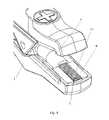
- FIG. 7is the enlarged figure of cluster-like conductive materials of second application example in this invention.
- FIG. 8displays how the conductive material of the cable is divided into two parts in this invention.
- FIG. 9is the third application example of the clamping device in this invention.
- a high conductivity energy-saving clamping devicecomprises a clamp 1 , a cable 4 fixed upon clamp 1 and an insulation plate 6 set inside a juncture at the mouth of clamp 1 .
- Conductive material 5 in the cable 4extends and is set on the juncture where clamp 1 connects the external conductor. When clamp 1 connects the external conductor, conductive material 5 directly contacts and grips the external conductor.
- conductive material 5(usually copper or other metal wires) is plainly set on one part of the juncture at the mouth of clamp 1 , and the front end of conductive material 5 is fixed between the mouth of clamp 1 and the insulation plate 6 (in this embodiment, insulation plate 6 is made of plastics).
- Conductive surface 51is formed on the surface of the insulation plate 6 .
- clamp 1connects an external conductor (a wiring terminal for instance), conductive surface 51 directly contacts the wiring terminal to effect electric conduction. Due to the effective increase in contact area, the conductivity performance of the clamping device in this invention is 10% to 15% higher than that of common clamps with known technology.
- the metallic members in this embodimentmay comprise a contact region (not shown in the figures) which extends outside the juncture at the mouth of the clamping device.
- the contact region of the metallic memberscontacts and grips the external conductor directly.
- conductive material 5 protrudes from the cable 4can be divided into two parts, which are plainly set on two parts of the juncture at the mouth of clamp 1 respectively.
- Two conductive surfaces 51are thus formed, which directly contact and grip the external conductor. Both of the two parts of the juncture at the mouth of the clamp can conduct electricity.
- conductive material 5goes through a through hole of the insulation plate 6 and extends from the top of the insulation plate 6 to form cluster-like conductive material 52 .
- clamp 1we open the head of clamp 1 to entirely expose the cluster-like conductive material 52 .
- clamp 1connects an external conductor, such as a wiring terminal
- cluster-like conductive material 52contacts the wiring terminal, and electric conduction is achieved. Due to effectively increased contact area, the conductivity performance of the clamping device of this invention is 10% to 15% higher than that of common clamps of known technology.
- conductive material 5 from the cable 4is divided into two parts.
- One part plainly set on one part of the juncture at the mouth of clamp 1forms the conductive surface 51 and another part vertically extending from another part of the juncture at the mouth of clamp 1 forms cluster-like conductive material 52 .
- clamp 1connects the external conductor (a wiring terminal for instance), conductive surface 51 and cluster-like conductive material 52 directly contact the wiring terminal to conduct electricity. Due to the effective increase in contact area, the conductivity performance of the clamping device in this invention is 10% to 15% higher than that of common clamps with known technology.
- the inventionhas the following advantages:
- the inventionemploys conductive materials to directly connect the external conductor so as to effectively increase the contact area. Therefore, its conductivity performance is 10% to 15% higher than that of the clamp with known technology adopting the tooth-like conductive parts to connect the cable with the external conductor.
- the inventioncan be applied to various products with different forms, which will enhance the recognition of the invention indirectly.
- the inventioncan be used in all sorts of electric circuit connection via clamps with a wide application range.
Landscapes
- Connections Effected By Soldering, Adhesion, Or Permanent Deformation (AREA)
- Installation Of Indoor Wiring (AREA)
- Clamps And Clips (AREA)
Abstract
Description
Claims (11)
Applications Claiming Priority (4)
| Application Number | Priority Date | Filing Date | Title |
|---|---|---|---|
| CN2010101391057ACN101814663B (en) | 2010-04-02 | 2010-04-02 | High conductivity energy saving clamp |
| CN201010139105 | 2010-04-02 | ||
| CN201010139105.7 | 2010-04-02 | ||
| PCT/CN2010/001016WO2011120207A1 (en) | 2010-04-02 | 2010-07-09 | High conductive energy-saving clip |
Publications (2)
| Publication Number | Publication Date |
|---|---|
| US20110287673A1 US20110287673A1 (en) | 2011-11-24 |
| US8342892B2true US8342892B2 (en) | 2013-01-01 |
Family
ID=42621824
Family Applications (1)
| Application Number | Title | Priority Date | Filing Date |
|---|---|---|---|
| US13/126,149Expired - Fee RelatedUS8342892B2 (en) | 2010-04-02 | 2010-07-09 | High conductivity energy-saving clamping device |
Country Status (4)
| Country | Link |
|---|---|
| US (1) | US8342892B2 (en) |
| EP (1) | EP2555330A4 (en) |
| CN (1) | CN101814663B (en) |
| WO (1) | WO2011120207A1 (en) |
Cited By (19)
| Publication number | Priority date | Publication date | Assignee | Title |
|---|---|---|---|---|
| USD726109S1 (en)* | 2014-04-01 | 2015-04-07 | The Noco Company | Electrical clamp |
| USD735665S1 (en)* | 2014-04-01 | 2015-08-04 | The Noco Company | Electrical clamp |
| USD738307S1 (en)* | 2014-04-01 | 2015-09-08 | The Noco Company | Electrical clamp |
| USD738825S1 (en)* | 2014-04-01 | 2015-09-15 | The Noco Company | Electrical clamp |
| US20170054232A1 (en)* | 2015-08-18 | 2017-02-23 | Gerard M. Toscani | Jumper clamps |
| USD794565S1 (en)* | 2016-06-28 | 2017-08-15 | Premier Technologies Ltd. | Battery clamp |
| US20190145796A1 (en)* | 2015-08-12 | 2019-05-16 | Infineon Technologies Ag | Angle sensing in an off-axis configuration |
| USD913934S1 (en)* | 2018-10-01 | 2021-03-23 | The Noco Company | Battery clamp |
| USD913938S1 (en)* | 2018-10-03 | 2021-03-23 | The Noco Company | Battery clamp |
| USD913933S1 (en)* | 2018-10-01 | 2021-03-23 | The Noco Company | Battery clamp |
| USD913937S1 (en)* | 2018-10-03 | 2021-03-23 | The Noco Company | Battery clamp |
| USD913935S1 (en)* | 2018-10-01 | 2021-03-23 | The Noco Company | Battery clamp |
| US11121485B2 (en)* | 2019-04-16 | 2021-09-14 | The Noco Company | Battery clamp device |
| USD984381S1 (en) | 2020-11-25 | 2023-04-25 | The Noco Company | Battery cable assembly for jump starting device |
| USD984383S1 (en) | 2021-06-08 | 2023-04-25 | Martin Koebler | Battery clamp |
| USD991186S1 (en) | 2020-12-11 | 2023-07-04 | The Noco Company | Battery cable assembly |
| USD991185S1 (en) | 2020-12-11 | 2023-07-04 | The Noco Company | Battery cable assembly |
| USD997102S1 (en)* | 2018-10-03 | 2023-08-29 | The Noco Company | Battery clamp |
| USD1067187S1 (en) | 2018-10-05 | 2025-03-18 | The Noco Company | Battery clamp |
Families Citing this family (14)
| Publication number | Priority date | Publication date | Assignee | Title |
|---|---|---|---|---|
| CN102354819A (en)* | 2011-08-23 | 2012-02-15 | 四川省电力公司攀枝花电业局 | Forcipated connecting device of emergency power generation vehicle |
| WO2014059644A1 (en)* | 2012-10-18 | 2014-04-24 | Zhao Lin | Gold finger connection device |
| CN102983472B (en)* | 2012-11-30 | 2015-03-11 | 山东金阳矿业集团有限公司 | Large-current rapid connection device for charging storage battery |
| DE102013211058B3 (en)* | 2013-06-13 | 2014-10-23 | Lisa Dräxlmaier GmbH | Current contact pliers for a four-wire measurement in the range of high voltage and high current |
| CN103354309A (en)* | 2013-07-24 | 2013-10-16 | 南京南车浦镇城轨车辆有限责任公司 | Conduction detection crocodile clip for cable wiring terminal |
| GB2512717B (en)* | 2014-02-11 | 2015-03-18 | Megger Instr Ltd | Electrical connection apparatus |
| USD911936S1 (en) | 2019-03-27 | 2021-03-02 | Halo International SEZC Ltd. | Portable power charger with air compressor hose |
| US10141755B2 (en)* | 2014-09-09 | 2018-11-27 | Halo International SEZC Ltd. | Multi-functional portable power charger |
| US9819204B2 (en) | 2014-09-09 | 2017-11-14 | Halo International SEZC Ltd. | Multi-functional high-capacity portable power charger |
| USD830301S1 (en)* | 2016-01-20 | 2018-10-09 | Paris Business Products, Inc. | Jumper clamp |
| CN115940315A (en)* | 2016-07-05 | 2023-04-07 | 博林格工业公司 | Multifunctional portable power supply charger |
| CN106486705B (en)* | 2016-10-27 | 2019-05-10 | 超威电源有限公司 | Battery chemical conversion connection folder |
| CN108267619A (en)* | 2017-12-31 | 2018-07-10 | 江苏启源雷宇电气科技有限公司 | A kind of self-regulation fixture by capacitor pipeline high current |
| USD1056662S1 (en)* | 2022-08-16 | 2025-01-07 | Farwater LLC | Hand tool |
Citations (18)
| Publication number | Priority date | Publication date | Assignee | Title |
|---|---|---|---|---|
| US2595057A (en)* | 1948-04-02 | 1952-04-29 | Carl S Epps | Coupling |
| US2972125A (en)* | 1959-01-08 | 1961-02-14 | Ici Australia Ltd | Separable electrical connection |
| US3019410A (en)* | 1959-10-12 | 1962-01-30 | Thomas & Betts Corp | Wire-to-wire connection |
| US3855567A (en)* | 1973-03-13 | 1974-12-17 | Gardner Denver Co | Electrical connector and method for making an electrical circuit |
| US4138188A (en)* | 1977-12-21 | 1979-02-06 | Amp Incorporated | Coaxial cable plug with center conductor as center contact |
| US4494812A (en)* | 1983-03-14 | 1985-01-22 | Bolton John D | Wire brush battery connector |
| US4934957A (en)* | 1989-08-15 | 1990-06-19 | Bellusci Albert V | Automotive battery terminal clamp for a battery jumper cable |
| US5564951A (en)* | 1994-02-23 | 1996-10-15 | Baxter International Inc. | Electrical cable connector and method of making |
| US5601452A (en)* | 1995-10-03 | 1997-02-11 | The United States Of America As Represented By The Secretary Of The Navy | Non-arcing clamp for automotive battery jumper cables |
| US6010371A (en)* | 1997-04-24 | 2000-01-04 | Abbott Laboratories | Electrical connector |
| CN2424540Y (en) | 2000-05-26 | 2001-03-21 | 上海广为电器工具厂 | Enerlgy saving storage battery clips |
| US6386907B1 (en)* | 1999-10-05 | 2002-05-14 | The United States Of America As Represented By The Secretary Of The Navy | Battery clamp |
| US6793537B2 (en)* | 2002-12-30 | 2004-09-21 | Methode Electronics, Inc. | Wire connector assembly and method of forming same |
| US6871387B2 (en) | 2003-03-07 | 2005-03-29 | Wen Tsung Cheng | Alligator clip structure |
| CN2751455Y (en) | 2004-09-27 | 2006-01-11 | 吴月琴 | Folding type electric clamp |
| US7322851B2 (en)* | 2006-01-27 | 2008-01-29 | Jeffrey Brookmire | Coaxial cable connector |
| CN101136512A (en) | 2006-09-01 | 2008-03-05 | 科汇工业有限公司 | Rechargeable battery wiring clip |
| CN201038356Y (en) | 2007-04-20 | 2008-03-19 | 建德市天宇五金电器有限公司 | Storage battery clip |
Family Cites Families (8)
| Publication number | Priority date | Publication date | Assignee | Title |
|---|---|---|---|---|
| DE3828148A1 (en)* | 1988-08-19 | 1990-02-22 | Ap Products Gmbh | CLIP OR CLAMP-LIKE TEST PLUG AND METHOD FOR PRODUCING SUCH A TEST PLUG |
| US5772468A (en)* | 1996-09-27 | 1998-06-30 | Coleman Cable System, Inc. | Clamp assembly for a battery booster cable |
| JP2001052781A (en)* | 1999-08-13 | 2001-02-23 | Hashi:Kk | Clip for booster cable |
| CN2394338Y (en)* | 1999-09-08 | 2000-08-30 | 大铭电业股份有限公司 | Personal Grounding Wire Set |
| EP1579534A1 (en)* | 2002-12-20 | 2005-09-28 | Koninklijke Philips Electronics N.V. | Double connector for medical sensor |
| US6980863B2 (en)* | 2003-03-20 | 2005-12-27 | Medtronic, Inc. | Neurological stimulation lead extension |
| CN2906962Y (en)* | 2006-05-29 | 2007-05-30 | 包建平 | Double grip cover double line automobile charging cable |
| CN201655988U (en)* | 2010-04-02 | 2010-11-24 | 上海广为电器工具有限公司 | Energy-saving clip using conductive materials to directly contact with conductor |
- 2010
- 2010-04-02CNCN2010101391057Apatent/CN101814663B/enactiveActive
- 2010-07-09EPEP10819674.2Apatent/EP2555330A4/ennot_activeWithdrawn
- 2010-07-09WOPCT/CN2010/001016patent/WO2011120207A1/enactiveApplication Filing
- 2010-07-09USUS13/126,149patent/US8342892B2/ennot_activeExpired - Fee Related
Patent Citations (18)
| Publication number | Priority date | Publication date | Assignee | Title |
|---|---|---|---|---|
| US2595057A (en)* | 1948-04-02 | 1952-04-29 | Carl S Epps | Coupling |
| US2972125A (en)* | 1959-01-08 | 1961-02-14 | Ici Australia Ltd | Separable electrical connection |
| US3019410A (en)* | 1959-10-12 | 1962-01-30 | Thomas & Betts Corp | Wire-to-wire connection |
| US3855567A (en)* | 1973-03-13 | 1974-12-17 | Gardner Denver Co | Electrical connector and method for making an electrical circuit |
| US4138188A (en)* | 1977-12-21 | 1979-02-06 | Amp Incorporated | Coaxial cable plug with center conductor as center contact |
| US4494812A (en)* | 1983-03-14 | 1985-01-22 | Bolton John D | Wire brush battery connector |
| US4934957A (en)* | 1989-08-15 | 1990-06-19 | Bellusci Albert V | Automotive battery terminal clamp for a battery jumper cable |
| US5564951A (en)* | 1994-02-23 | 1996-10-15 | Baxter International Inc. | Electrical cable connector and method of making |
| US5601452A (en)* | 1995-10-03 | 1997-02-11 | The United States Of America As Represented By The Secretary Of The Navy | Non-arcing clamp for automotive battery jumper cables |
| US6010371A (en)* | 1997-04-24 | 2000-01-04 | Abbott Laboratories | Electrical connector |
| US6386907B1 (en)* | 1999-10-05 | 2002-05-14 | The United States Of America As Represented By The Secretary Of The Navy | Battery clamp |
| CN2424540Y (en) | 2000-05-26 | 2001-03-21 | 上海广为电器工具厂 | Enerlgy saving storage battery clips |
| US6793537B2 (en)* | 2002-12-30 | 2004-09-21 | Methode Electronics, Inc. | Wire connector assembly and method of forming same |
| US6871387B2 (en) | 2003-03-07 | 2005-03-29 | Wen Tsung Cheng | Alligator clip structure |
| CN2751455Y (en) | 2004-09-27 | 2006-01-11 | 吴月琴 | Folding type electric clamp |
| US7322851B2 (en)* | 2006-01-27 | 2008-01-29 | Jeffrey Brookmire | Coaxial cable connector |
| CN101136512A (en) | 2006-09-01 | 2008-03-05 | 科汇工业有限公司 | Rechargeable battery wiring clip |
| CN201038356Y (en) | 2007-04-20 | 2008-03-19 | 建德市天宇五金电器有限公司 | Storage battery clip |
Non-Patent Citations (1)
| Title |
|---|
| Search Report for PCT/CN10/01016 dated Jan. 6, 2011. |
Cited By (31)
| Publication number | Priority date | Publication date | Assignee | Title |
|---|---|---|---|---|
| USD735665S1 (en)* | 2014-04-01 | 2015-08-04 | The Noco Company | Electrical clamp |
| USD738307S1 (en)* | 2014-04-01 | 2015-09-08 | The Noco Company | Electrical clamp |
| USD738825S1 (en)* | 2014-04-01 | 2015-09-15 | The Noco Company | Electrical clamp |
| USD726109S1 (en)* | 2014-04-01 | 2015-04-07 | The Noco Company | Electrical clamp |
| US10732009B2 (en)* | 2015-08-12 | 2020-08-04 | Infineon Technologies Ag | Angle sensing in an off-axis configuration |
| US20190145796A1 (en)* | 2015-08-12 | 2019-05-16 | Infineon Technologies Ag | Angle sensing in an off-axis configuration |
| US20170054232A1 (en)* | 2015-08-18 | 2017-02-23 | Gerard M. Toscani | Jumper clamps |
| US9692155B2 (en)* | 2015-08-18 | 2017-06-27 | Paris Business Products, Inc. | Jumper clamps |
| USD794565S1 (en)* | 2016-06-28 | 2017-08-15 | Premier Technologies Ltd. | Battery clamp |
| USD913934S1 (en)* | 2018-10-01 | 2021-03-23 | The Noco Company | Battery clamp |
| USD1066252S1 (en) | 2018-10-01 | 2025-03-11 | The Noco Company | Battery clamp |
| USD913933S1 (en)* | 2018-10-01 | 2021-03-23 | The Noco Company | Battery clamp |
| USD1063845S1 (en) | 2018-10-01 | 2025-02-25 | The Noco Company | Battery clamp |
| USD913935S1 (en)* | 2018-10-01 | 2021-03-23 | The Noco Company | Battery clamp |
| USD991177S1 (en) | 2018-10-01 | 2023-07-04 | The Noco Company | Battery clamp |
| USD993920S1 (en) | 2018-10-03 | 2023-08-01 | The Noco Company | Battery clamp |
| USD1055859S1 (en) | 2018-10-03 | 2024-12-31 | The Noco Company | Battery clamp |
| USD988999S1 (en) | 2018-10-03 | 2023-06-13 | The Noco Company | Battery clamp |
| USD1093314S1 (en) | 2018-10-03 | 2025-09-16 | The Noco Company | Battery clamp |
| USD913938S1 (en)* | 2018-10-03 | 2021-03-23 | The Noco Company | Battery clamp |
| USD913937S1 (en)* | 2018-10-03 | 2021-03-23 | The Noco Company | Battery clamp |
| USD1004550S1 (en) | 2018-10-03 | 2023-11-14 | The Noco Company | Battery clamp |
| USD997102S1 (en)* | 2018-10-03 | 2023-08-29 | The Noco Company | Battery clamp |
| USD1003833S1 (en) | 2018-10-03 | 2023-11-07 | The Noco Company | Battery clamp |
| USD1067187S1 (en) | 2018-10-05 | 2025-03-18 | The Noco Company | Battery clamp |
| US11121485B2 (en)* | 2019-04-16 | 2021-09-14 | The Noco Company | Battery clamp device |
| USD984381S1 (en) | 2020-11-25 | 2023-04-25 | The Noco Company | Battery cable assembly for jump starting device |
| USD1058517S1 (en) | 2020-12-11 | 2025-01-21 | The Noco Company | Battery cable assembly |
| USD991185S1 (en) | 2020-12-11 | 2023-07-04 | The Noco Company | Battery cable assembly |
| USD991186S1 (en) | 2020-12-11 | 2023-07-04 | The Noco Company | Battery cable assembly |
| USD984383S1 (en) | 2021-06-08 | 2023-04-25 | Martin Koebler | Battery clamp |
Also Published As
| Publication number | Publication date |
|---|---|
| WO2011120207A1 (en) | 2011-10-06 |
| US20110287673A1 (en) | 2011-11-24 |
| EP2555330A4 (en) | 2013-08-14 |
| CN101814663A (en) | 2010-08-25 |
| CN101814663B (en) | 2012-01-18 |
| EP2555330A1 (en) | 2013-02-06 |
Similar Documents
| Publication | Publication Date | Title |
|---|---|---|
| US8342892B2 (en) | High conductivity energy-saving clamping device | |
| CN102195217B (en) | Connector | |
| US10707593B2 (en) | Terminal assembly for electrical device and electrical device | |
| CN113078509A (en) | Wire harness terminal | |
| CA2738156C (en) | A high conductivity energy-saving clamping device | |
| CN205335455U (en) | Novel copper terminal for cable junction | |
| US11411331B2 (en) | Hybrid type wire-to-wire connector structure and power supply device having the same | |
| US10566720B2 (en) | Simple electrical connector structure connecting a ribbon cable and a printed circuit board | |
| CN217387575U (en) | Connector for electric automobile and vehicle with connector | |
| CN207069188U (en) | A kind of safety-type termination | |
| CN206135121U (en) | Novel stromatolite is female to be arranged | |
| CN212182632U (en) | Wiring terminal with improved structure of copper tin-plated metal sheet | |
| JP2022050508A5 (en) | Wire/cable connection structure and wire/cable connection method | |
| CN102709717A (en) | Single-core-wire connector terminal | |
| CN202178653U (en) | Junction box | |
| CN2750499Y (en) | Coaxial cable connector | |
| CN206497997U (en) | Copper-aluminium transition equipment cable clamp | |
| CN207074743U (en) | A kind of connector | |
| CN203645008U (en) | Wiring terminal | |
| CN204167549U (en) | A kind of pin connector for single row of pins | |
| CN213279091U (en) | Conductive strain clamp | |
| CN2789951Y (en) | Quick connection card | |
| CN213692386U (en) | Wiring device for electric power engineering | |
| CN221379793U (en) | Connecting wire harness | |
| CN220066107U (en) | A press fastening structure and a cold-pressed terminal for convenient signal collection |
Legal Events
| Date | Code | Title | Description |
|---|---|---|---|
| AS | Assignment | Owner name:SHANGHAI POWER STATION CO., LTD., CHINA Free format text:ASSIGNMENT OF ASSIGNORS INTEREST;ASSIGNORS:FAN, YEPING;WU, YONG;YAN, ZHANGXI;AND OTHERS;REEL/FRAME:026184/0481 Effective date:20110414 Owner name:SHANGHAI GREATWAY TOP POWER CO., LTD., CHINA Free format text:ASSIGNMENT OF ASSIGNORS INTEREST;ASSIGNORS:FAN, YEPING;WU, YONG;YAN, ZHANGXI;AND OTHERS;REEL/FRAME:026184/0481 Effective date:20110414 Owner name:SHANGHAI GUANGWEI ELECTRIC & TOOLS CO., LTD, CHINA Free format text:ASSIGNMENT OF ASSIGNORS INTEREST;ASSIGNORS:FAN, YEPING;WU, YONG;YAN, ZHANGXI;AND OTHERS;REEL/FRAME:026184/0481 Effective date:20110414 | |
| STCF | Information on status: patent grant | Free format text:PATENTED CASE | |
| FPAY | Fee payment | Year of fee payment:4 | |
| MAFP | Maintenance fee payment | Free format text:PAYMENT OF MAINTENANCE FEE, 8TH YEAR, LARGE ENTITY (ORIGINAL EVENT CODE: M1552); ENTITY STATUS OF PATENT OWNER: LARGE ENTITY Year of fee payment:8 | |
| FEPP | Fee payment procedure | Free format text:MAINTENANCE FEE REMINDER MAILED (ORIGINAL EVENT CODE: REM.); ENTITY STATUS OF PATENT OWNER: LARGE ENTITY | |
| LAPS | Lapse for failure to pay maintenance fees | Free format text:PATENT EXPIRED FOR FAILURE TO PAY MAINTENANCE FEES (ORIGINAL EVENT CODE: EXP.); ENTITY STATUS OF PATENT OWNER: LARGE ENTITY | |
| STCH | Information on status: patent discontinuation | Free format text:PATENT EXPIRED DUE TO NONPAYMENT OF MAINTENANCE FEES UNDER 37 CFR 1.362 | |
| FP | Lapsed due to failure to pay maintenance fee | Effective date:20250101 |