US8342474B2 - Modular support, assemblies, methods and systems - Google Patents
Modular support, assemblies, methods and systemsDownload PDFInfo
- Publication number
- US8342474B2 US8342474B2US12/380,996US38099609AUS8342474B2US 8342474 B2US8342474 B2US 8342474B2US 38099609 AUS38099609 AUS 38099609AUS 8342474 B2US8342474 B2US 8342474B2
- Authority
- US
- United States
- Prior art keywords
- module
- modules
- support
- support assembly
- halves
- Prior art date
- Legal status (The legal status is an assumption and is not a legal conclusion. Google has not performed a legal analysis and makes no representation as to the accuracy of the status listed.)
- Expired - Fee Related
Links
- 238000000034methodMethods0.000titleclaimsdescription27
- 238000000429assemblyMethods0.000titledescription7
- 230000000712assemblyEffects0.000titledescription7
- 239000012530fluidSubstances0.000claimsabstractdescription30
- 230000000717retained effectEffects0.000claimsabstractdescription13
- 239000000463materialSubstances0.000claimsdescription24
- 125000006850spacer groupChemical group0.000claimsdescription17
- 230000007480spreadingEffects0.000claimsdescription4
- 238000003892spreadingMethods0.000claimsdescription4
- 230000003247decreasing effectEffects0.000claims2
- 230000008859changeEffects0.000abstractdescription3
- 230000008901benefitEffects0.000description17
- 238000009434installationMethods0.000description13
- 238000010276constructionMethods0.000description9
- 238000013461designMethods0.000description7
- 230000007246mechanismEffects0.000description7
- 238000004519manufacturing processMethods0.000description6
- 230000009286beneficial effectEffects0.000description5
- 239000002184metalSubstances0.000description4
- 239000000203mixtureSubstances0.000description4
- 230000008569processEffects0.000description4
- 238000007792additionMethods0.000description3
- 238000012423maintenanceMethods0.000description3
- 230000013011matingEffects0.000description3
- 238000000465mouldingMethods0.000description3
- 230000008520organizationEffects0.000description3
- 230000008439repair processEffects0.000description3
- 229910000831SteelInorganic materials0.000description2
- 230000000295complement effectEffects0.000description2
- 210000001145finger jointAnatomy0.000description2
- 230000006870functionEffects0.000description2
- 230000002401inhibitory effectEffects0.000description2
- 238000003780insertionMethods0.000description2
- 230000037431insertionEffects0.000description2
- 238000000926separation methodMethods0.000description2
- 239000010959steelSubstances0.000description2
- 230000004075alterationEffects0.000description1
- 239000000919ceramicSubstances0.000description1
- 239000002131composite materialSubstances0.000description1
- 230000008878couplingEffects0.000description1
- 238000010168coupling processMethods0.000description1
- 238000005859coupling reactionMethods0.000description1
- 230000003292diminished effectEffects0.000description1
- 230000005684electric fieldEffects0.000description1
- 230000007613environmental effectEffects0.000description1
- 231100001261hazardousToxicity0.000description1
- 238000009413insulationMethods0.000description1
- 238000005304joiningMethods0.000description1
- 238000009533lab testMethods0.000description1
- 239000002991molded plasticSubstances0.000description1
- 239000002086nanomaterialSubstances0.000description1
- 230000003864performance functionEffects0.000description1
- 230000002093peripheral effectEffects0.000description1
- 230000021715photosynthesis, light harvestingEffects0.000description1
- 229920000642polymerPolymers0.000description1
- 239000012858resilient materialSubstances0.000description1
- 230000002269spontaneous effectEffects0.000description1
- 238000003860storageMethods0.000description1
- 238000005728strengtheningMethods0.000description1
- 238000006467substitution reactionMethods0.000description1
- 230000003319supportive effectEffects0.000description1
- 238000003466weldingMethods0.000description1
Images


Classifications
- F—MECHANICAL ENGINEERING; LIGHTING; HEATING; WEAPONS; BLASTING
- F16—ENGINEERING ELEMENTS AND UNITS; GENERAL MEASURES FOR PRODUCING AND MAINTAINING EFFECTIVE FUNCTIONING OF MACHINES OR INSTALLATIONS; THERMAL INSULATION IN GENERAL
- F16L—PIPES; JOINTS OR FITTINGS FOR PIPES; SUPPORTS FOR PIPES, CABLES OR PROTECTIVE TUBING; MEANS FOR THERMAL INSULATION IN GENERAL
- F16L3/00—Supports for pipes, cables or protective tubing, e.g. hangers, holders, clamps, cleats, clips, brackets
- F16L3/22—Supports for pipes, cables or protective tubing, e.g. hangers, holders, clamps, cleats, clips, brackets specially adapted for supporting a number of parallel pipes at intervals
- F16L3/222—Supports for pipes, cables or protective tubing, e.g. hangers, holders, clamps, cleats, clips, brackets specially adapted for supporting a number of parallel pipes at intervals having single supports directly connected together
Definitions
- This inventionrelates generally to support systems for objects, more particularly to modular assemblies for supporting elongated objects that may be primarily cylindrical in shape, and specifically to assemblies of interchangeable modules of differing or similar sizes to create adjustable assemblies whose overall shape and number of modules can vary depending upon the intended use of an assembly.
- Supports for generally cylindrical objects, including fluid conduits such as hydraulic pipe, tube, and hose,are known.
- Such supportstypically include an apparatus that securely receives and stores bundles of pipes, tubes and/or hoses while maintaining separation of individual lines.
- the support apparatususually includes supportive blocks or clips that may be welded to the conduits in an expensive process that requires post-finishing operations, and these blocks may have several unique, difficult to install parts that are made specifically for the application.
- the blocksmay be attached to each other by independent attachment pieces. These attachment pieces may comprise vertical locking strips that engage with the blocks to affix one block to the next.
- Each blockmay comprise several apertures, so that within each block, several hoses may be received.
- support members having vertical rows of aperturesmay comprise retaining arms that hingedly extend from a base portion of the support member and snap into a top portion of the support member to retain the hoses.
- One disadvantage of this systemis that if the arm is not properly locked into place, there exists no tell-tale sign that anything is amiss.
- Still other supportsinclude blocks that can be stacked on top of one another but not side-by-side.
- each support portion or blocktypically comprises a multitude of apertures to receive multiple pipes. Therefore, in order to add/remove one pipe to/from an assembly of pipes, an entire row of apertures (and therefore one block) must be removed to access the intermediate row of pipes that retains the desired pipe. As such, the overall configuration of the assembly is altered. In most cases, this requires removing the inhibiting surrounding row(s), disrupting the entire assembly, and increasing labor cost. Disassembling the entire assembly becomes impossible in areas having low clearances such as certain equipment, mechanical rooms and other storage locations, trucks, trailers, and other transport vehicles.
- the support portions or blocks of most currently available hose and pipe support systemsrely on a separate means of attachment to affix one support portion or block to the next.
- these separate means of attachmentcomprise bolts, which negatively impact the cost of materials and installation.
- the present inventionis directed to systems and methods which provide secure, variable, modular support for multiple objects.
- An example of a support system that exhibits superior organization of objectscan be seen in embodiments of the present invention.
- the present modular support assemblycomprises a system of bracketry in the form of modules that can be put together in many configurations and used in a multitude of applications.
- the present modular support assemblies, methods and systemsadvantageously provide a flexibility to capture individual conduits and then lock multiple conduits together in various configurations, as needs may dictate.
- the modular support assemblycan be used to support and transport many types of objects, particularly elongated objects
- the modular support assemblyis preferably used for the housing, transport, and support of elongated objects having a generally cylindrical cross-section, such as individual and bundled fluid conduits, including hydraulic hoses, tubes, and pipes.
- the use of a modular configurationresults in reduced part count and cost via standardization, and allows fluid conduits to be pre-bundled at the supplier level prior to equipment installation.
- the present modular support assemblymay therefore be an attractive stock item for fluid conduit distributors.
- the present modular support assemblycomprises an assembly of these interchangeable modules.
- the modulescan comprise a variety of sizes and can be placed around the fluid conduits either before or after the conduits have been bundled or placed.
- Each individual modulecomprises an aperture that receives one conduit.
- the ability to place the module around (or onto) the conduit before or after installation of the conduitis made possible by sliding the entire module over/onto the conduit or by providing modules that comprise two, preferably interchangeable module portions or halves, each portion comprising approximately one half of the module, wherein the portions are slidably removable from one another along a longitudinal plane of the conduit retained therein.
- Other embodiments of the present inventionmay provide modules having two parts that differ vastly in size. Each module can be removed from the assembly in its entirety or in part. When one module portion is removed from the other module portion, a “pick and place” method of inserting the conduit into the module's aperture can be employed. This is a very beneficial feature of the design because it allows for conduit accessibility and maneuverability in tight spaces.
- An important advantage of the present embodimentis that a module can be moved to different parts of the assembly, including beside or underneath another module.
- the ability to move the modules from beside one another to below/above one anotherprovides versatility in support.
- a flipped modulecould act as a spacer during emergency repair.
- a further advantage of each module receiving one conduitis that removal of one object can be achieved while maintaining the overall structure of a modular support assembly.
- the present inventionprovides a non-disruptive, easy to implement method of storing, transporting, and separating objects, including hydraulic fluid conduits and becomes very beneficial when long lengths of pipe or tube are transported or installed together.
- the modulesare cube-like in structure, having six sides.
- the dimensions and shape of the modulescan vary depending upon the intended use of the assembly. For example, modules having a thickness that is greater than their width and height dimensions may be well suited for large diameter, heavy conduits.
- similarly and differently-sized modulesare engaged with one another by a system of slidable, inter-locking engagement portions, such as slide and groove fasteners or joints, disposed along the periphery of the modules.
- the slide and groove jointsmay include interlocking fan-shaped tails and sockets as seen in sliding dovetail joints.
- Each blockhas, on at least four of its sides, including the top, bottom, left, and right sides, alternating tails and sockets.
- the interlocking fan-shaped tails and socketsmay be chamfered to create a minimal amount of friction between the tails and sockets. This may be of particular use during installation.
- the tails and socketscould comprise any type of finished shape and/or cross-section.
- some embodiments of the modular assemblymay comprise modules of a rigid or semi-rigid material, it should be understood that any material could be used in the construction of the modules, depending upon the intended use of individual modules or of the entire assembly.
- a benefit of various embodimentsis the ability to bundle together different families of tubes having different performance functions by providing a dedicated aperture in each module so that when an assembly houses different types of tubes, it becomes easy to pair a module of one material with a module of a different material.
- the material used in the construction of the modulescan therefore comprise polymer, metal, ceramic, metal infused, nano-materials, or any other material.
- ID linesare the hardest to bend and maneuver, especially in tight spaces.
- small ID hosescan be routed in tighter areas, making future changes or additions convenient.
- Various embodiments of the present inventionprovide a system in which any size of hose could be inserted, maintained, or removed and replaced without disrupting the overall shape of the assembly.
- Each modulecan be modified to accommodate objects of varying cross-section.
- Aperture insertsmay be employed to alter the size and/or shape of the original aperture to accommodate varying sizes of fluid conduits with a module.
- a method of adding and removing at least one module, that receives an object, to an assembly of a plurality of modulesmay comprise sliding the modules relative to one another in an engageable/disengageable and interchangeable fashion along a longitudinal plane of the object received therein, and separating the modules from one another by removing portions of the modules from the modules to remove the object received therein, while the assembly of modules maintains its original structural integrity.
- the modules thus slidably engaged with one anothermay comprise varying sizes, or inserts of varying sizes, to facilitate storing and transporting objects of varying sizes.
- a support assembly for supporting and maintaining separation of hoses, tubes, and pipesmay comprise a plurality of support modules.
- Each support modulemay comprise an aperture that receives a hose, tube, pipe, or the like, and may have at least one engagement portion disposed along a periphery of the support module.
- the support modulesmay be removably attachable to and in exchangeable relationship with each other by engaging the engagement portions such that the support modules cooperate in a removable yet generally rigid manner.
- the support modulesmay vary in size to accommodate varying sizes of hose, tube, or pipe retained therein, and are preferably interchangeably engaged with one another.
- Hose supportsare particularly desirable when hoses or tubes need to be braced to equipment and kept in place, or when bundles of hoses or tubes are to be run alongside one another. Such support may be desirable at a hose flex point, for carrying hydraulic conduits overhead, for long tubes such as on a boom, or simply where several differing lines used in the same system converge in one location and it becomes desirable to maintain organization and identification of the individual lines.
- the present systemensures proper routing of the conduit(s).
- two main objectivesare kept in mind: to make the system as leakproof as possible, and to provide accessibility to the conduits for maintenance. It is commonly recommended that a replacement hose be rated at half the SAE bend radius specification as an original equipment hose in an application.
- the present systems and methodsaccommodate replacement hoses that may behave, move, and/or may be of a different size and material from their predecessor.
- the present systemis a lightweight, durable, and accessible support system that can provide reliable security for hoses, tubes, and pipes of various sizes, comprising modules that are easy to install around previously positioned conduits and that are just as easily disassembled.
- the present systems and methodsprovide a support system for hoses of varying applications within one bundle.
- hose bundles for hydraulic power steering systemscomprise a high pressure and a low pressure line. These lines may be of different diameter or material (e.g. one line might be a steel tube and the other a hose). It may be beneficial to provide different material for the high pressure line support module from that of the low pressure line support module material, as well as support for the different diameters.
- Another benefit of the present inventionis that is allows the interchange of modules of same or differing material and size depending upon the use of the assembly, allowing the same modules to be used in different applications.
- hose support for farm equipment and oil linesmay require heavy, durable modules that could be used for either application; conversely, the medical and dentistry industries could each employ and interchange modules that are smaller and lighter in weight to support light tubing.
- Hydraulic hoseis generally intended to flex, but not twist. Lab tests show that if a large inner diameter (ID), high-pressure hydraulic hose is twisted only seven degrees, its service life may be reduced by ninety percent. High-pressure hose should not be routed through several bends, and, when the hose must flex, it should be routed through the pivot point around which the hose traverses.
- the interchangeable system of differently-sized modules of the present inventioncan help maintain the optimum and most efficient flexing of the hose lines, and can provide efficient support to even short lengths of hose while keeping the hose within the contour of the machine. When a hose is pushed, rather than bent, the hose has a tendency to form an “S-bend”.
- Hydraulic hosescan elongate and contract during pressurization cycles.
- Embodiments of the present inventionprovide a system in which the material used to support the hoses preferably does not hinder fluid flow within the fluid conduit.
- Various materials used in the construction of the modulescould aid in energy dissipation, thermal insulation, or noise and vibration dampening.
- the present systems and methodsprovide a support assembly which is adjustable or alterable to readily permit the number of supported lines to vary, and allow types and sizes of couplings to be altered without redesigning the entire support structure.
- FIG. 1is an environmental perspective view of a modular support assembly employing an embodiment of the present invention and showing the ability of the modular support assembly to store differently-sized fluid conduits;
- FIG. 2is a front view of another possible combination of module embodiments, having a variety of apertures sizes, as well as an insert which may be used in some embodiments;
- FIG. 3is a front view of an assembly, similar to the assembly shown in FIG. 2 , with the right-most module removed;
- FIG. 4is a front view of the configuration of the assembly shown in FIG. 3 with a portion of the right-most module removed;
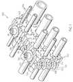
- FIG. 5is a reflected perspective view of an embodiment of a single module of the present invention, with the portions thereof separated;
- FIG. 6is a perspective view of another embodiment of a single module of the present invention, with the portions thereof joined together;
- FIG. 7is a perspective view of single module of FIG. 6 with the portion halves thereof separated;
- FIG. 8is a front view of n embodiment of a module of the present invention joined to a load spreading washer.
- FIG. 9is top view of the load spreading washer and module shown in FIG. 7 .
- embodiment 100 of the present inventionis shown supporting a varying number and sizes of elongated, generally cylindrical objects 104 .
- the cylindrical objectsmay comprise fluid conduits.
- the present assembliescan receive, support, transport, and store objects having virtually any cross section, including square, elliptical, oblong, or oval-shaped cross sections as well as objects of virtually any type or size including airplane fuselages or portions thereof, machinery parts, construction components, medical, sports, or other equipment, large oil pipe lines, transport vessels, etc.
- the fluid conduitsmay comprise hydraulic hose, pipe and tube.
- a bundle of various cross sections of conduitis supported by modular support assembly 100 comprised of modules 102 .
- Modules 102may comprise varying sizes and include an aperture 106 .
- Aperture 106may be sized to receive conduits of standard or non-standard sizes.
- Aperture 106may have a smooth edge and may be generally circular in shape.
- the size and shape of aperture 106may vary depending upon the type, size, and shape of the object to be received therein. As shown in FIG. 2 aperture 106 may receive insert halves 206 , which may be used to allow a module to accept a smaller conduit or the like.
- Insert halves 206may be “snap-fitted” in place by insertion of tab 208 into slot 210 defined by relief 107 .
- Tab 208may have a leg or catch extending backward into relief 107 , engaging the edge of slot 210 to help retain the insert in aperture 106 .
- modules 102may comprise engagement portions 108 .
- Engagement portions 108may comprise any type of engagement portion having the ability to fasten together two separate structures in a secure manner.
- engagement portions 108can be easily disengaged, such as by sliding, for example, in a plane that is longitudinal to the object retained therein.
- This ease of installation provided by easily disengageable, yet generally rigid, engagement portionsbecomes beneficial when it is desirable to place the module 102 around fluid conduit 104 or the like, particularly after the fluid conduit has been installed.
- Such engagement portionsfurther allow great versatility during installation which in turn cuts down on maintenance, installation, and manufacturing cost.
- the present inventionprovides a neat, simple, secure way of changing the configuration of assembly 100 very quickly in the field, while maintaining the original integrity of the assembly.
- Engagement portion 108can comprise tails 110 and sockets 112 , similar to dovetail joints found in woodworking.
- several sliding dovetail jointsare used to attach one module 102 to the next.
- the sliding dovetailsjoin two modules together, having intersection points all along the sides of the modules 102 .
- the continuous dovetail, or a portion thereofruns along the entire length of each of the top, bottom, left, and right sides of a module, and allows back and forth sliding betwixt two modules. This allows the modules to be disassembled from the assembly by moving the module fore or aft in relation to the assembly 100 . This allows flexibility and versatility in placing and removing each module 102 .
- engagement portions 108can be disposed on any or all sides of the module 102 , including the front and back sides.
- the conduits 104may be placed first, or the modules 102 may be assembled first and then the conduits placed therein.
- various embodiments of the present inventionsuch as illustrated module 602 may employ dovetails 610 , which are comprised of two dovetail portions 611 and 613 , defined by each of module portions 603 .
- each module 102comprises alternating tails 110 and sockets 112 .
- each module 102comprises alternating tails 110 and sockets 112 .
- the size, number, and shape of the engagement portions 108can vary, to include, for example, square or other-shaped corners.
- a modulecould comprise one large engagement portions per side, or several smaller engagement portions per side, depending upon the application of the module.
- the peripheral engagement portions, the dedicated aperture for storing only one object, and the ability to take apart each module 102 apartcreates a robust, easy to use system that, relative to other systems, costs far less to manufacture and operate.
- sliding jointsare utilized in the illustrated embodiments of the modular support assembly 100 , it should be understood that a module having an aperture that is dedicated to one object as well as engagement portions on all sides of the module can be contemplated wherein the engagement portions comprise fastening mechanisms other than a sliding mechanism. For example, one could envision snap-fit embodiments which may be useful.
- each module 102 of the illustrated embodimentscomprises two, generally identical, cooperative module portions or halves 103 .
- Each portion 103has a plurality of exterior engagement portions 108 , as described above. Again, the number, size, type and the configuration of engagement portions 108 can vary depending upon the intended use of the module 102 .
- Each portionalso includes an interlock key 126 and an interlock channel 128 to interexchangeably join the module portions together as described in greater detail below, with reference to FIGS. 5 and 6 .
- the modules 102further comprise a recess 114 , such that when modules abut one another, passage 116 is created.
- Passage 116may run through a central region of the module 102 , generally perpendicular to aperture 106 and/or dovetails 108 .
- a temporary securing fastener 118may be inserted into the passage 116 to help prevent the modules from sliding away from one another. While a certain amount of slip or movement may be contemplated in some circumstances, preferably the assembly 100 would be held together in a secure fashion where movement between the modules would be generally arrested.
- Temporary securing fasteners 118may be partially inserted into clearance 116 to keep adjacent modules 102 from sliding relative to one another during placement, refraining from locking the two modules together.
- the temporary fastenercould then be replaced by another, more permanent fastener, such as illustrated bolt 120 , once module 102 is in position.
- a ridge on pin 118may engage with a recess in passage 116 to keep pin 118 from sliding out of the passage.
- passage 116alternates between two different diameters along its length to provide a place for the pin ridge to engage.
- pin 118may also allow use of a smaller fastener if desired.
- Passage 116may receive a larger bolt, or pin 118 , with a smaller bolt passing through pin 118 to secure assembly 100 to a structure.
- the modulescould be assembled without the use of a fastener. For instance, there may be applications where the modules are simply used to separate fluid lines and not clamp them to equipment. Also, in a large bundle of lines, fewer fasteners may be used, and pins may be utilized to lock the dove tails of a module 102 not having an adjacent fastener. While many securing devices could be envisioned, such as a rod, expansion pin, bolt, or other such securing device, a spring pin may be used to secure the modules 102 relative to one another.
- Passage 116may be of any size to accept fasteners of standard and non-standard sizes. Passage 116 may or may not be threaded to accept and engage threaded fasteners; therefore, fasteners for non-threaded holes, such as those that expand to fill or draw up behind a metal plate, may also be used. Also shown in FIG. 1 is a sturdier securing fastener that can be easily removed from the module.
- the securing fastener in the illustrated embodiment of the present inventionis bolt 120 , employing washer 122 .
- Bolt 120may be any kind of bolt, such as a hex head, carriage, flange, shoulder, T-head, or cap screw (illustrated) and may pass through assembly 100 to secure the assembly to an underlying structure.
- Washer 122may comprise any type of washer including flat, spring lock, tooth lock, serrated tooth lock washers, and so on.
- Load spreading washer 146such as shown in FIGS. 7 and 8 , may be employed to further distribute the load imparted on the assembly 100 .
- Load-distributing washers 146may include engagement portions 150 that cooperate with engagement portions 108 located on the sides of modules 102 .
- a significant advantage of various embodiments of the present inventionis that the use of a bolt 120 , expansion pin 118 , or the like in the modular support assembly 100 is optional, potentially lowering manufacturing costs relative to other support systems for fluid conduits.
- the size of a fastener, such as bolt 120may be selected based on a particular application. For example the size of the bolt may be limited, to discourage over-torquing, which might lead to deformation of system modules and/or damage to fluid conduits retained therein.
- spacers 124 , 125may be provided to accommodate combinations of various sizes of modules that store various sizes of conduits.
- vertical spacer 124 in the corner of FIG. 1brings the height of the end stack up to match the adjacent stack so it can be bolted by bolt 120 . It has recess 114 on its short sides.
- Horizontal spacers 125 in the middle of FIG. 1fill in gaps.
- These spacerscan also be used with a single conduit so that a module 102 can be fastened. The spacer and module together create a fastener hole 116 for a single module 102 .
- spacers 124 and 125help position fluid conduits 104 in an advantageous manner within the fluid conduit bundle.
- the design of the modules 102allows for a staggered assembly, where a lower row of modules 102 may be offset from the row directly above.
- Such versatility in design and configuration of the modulesprovides a unique and useful method of securing fluid conduits, or the like.
- the spacers 124may comprise various dimensions, and may be placed within the assembly 100 in vertical or horizontal orientations. In accordance with the present invention, spacers 124 also have sliding dovetails engagement portions 108 , assembled by sliding one or more tails 110 into one or more sockets 112 .
- Spacers 124may also be used to complete passage 116 when only one fluid conduit 104 is to be clamped, and therefore may further comprise a recess 114 so as to leave undisrupted the configuration of the assembly 100 and retain the option of applying a pin 118 or bolt 120 for the additional securement of the modular support assembly 100 .
- Pin 118may also fit into a flattened passage formed by a horizontal spacer 125 and other module or vertical spacer 124 .
- FIG. 2illustrates examples of other embodiments of the present invention in which aperture 106 includes reliefs 107 .
- Apertures 106may comprise any shape or size, depending upon the desired use of the module.
- aperture 106may include reliefs 107 .
- Reliefs 107may be employed in both one-piece modules and two-piece modules and may extend all the way through the module or only partially into the module. These reliefs may comprise any shape or size, depending upon the desired use of the module 102 .
- Relief 107can provide strain relief and/or a certain amount of flex for insertion of conduits and/or assembly.
- Reliefs 107may also be used to accommodate at least one adapter or insert, such as inserts 206 shown in FIG. 2 .
- Inserts 206can be removably inserted to change the size and/or shape of aperture 106 to accommodate smaller or differently sized or shaped objects retained therein for a secure fit.
- An adaptermay comprise a smooth, wedge-shaped insert that could mate with a cooperating wedge-shaped insert disposed on an opposing surface of a conduit thereby surrounding the conduit snugly and securely without imposing pressure points to the conduit.
- a pressure point on a fluid conduitcan create potentially hazardous situations including weakness in the conduit and ultimately failure.
- the relief 107allows each size of module 102 to accommodate a range of fluid conduit sizes. In accordance with the present invention, there can be any number of reliefs 107 within module 102 .
- module 102may comprise one relief 107 having sleeves disposed between the module and the conduit to accommodate smaller conduit sizes.
- This innate flexibility in designallows the modular support assembly 100 to be used in practically any application including applications in the mechanical, automotive, construction, recreation, electrical, and housing industries.
- FIG. 3demonstrates the ease in which support module 102 can be removed, by sliding, in its entirety from Modular Support Assembly 100 , thus facilitating removal of a single conduit from a bundle.
- FIG. 4shows module half 103 removed from a module, a feature which can be used to further ease removal of a single conduit from a bundle.
- each module portion 103comprises either an interlock key 126 or an interlock channel 128 .
- the interlock key 126may comprise a trapezoidal shape end tail that neatly fits into the opposing module portion's interlock channel 128 .
- This interlock channelmay therefore comprise a cooperative end socket in the form of a trapezoidal-shaped groove or the like.
- the shape and size of the interlock key 126 and interlock channel 128can vary and any and all possible combinations of size and shape of complementary cross-section of these components are incorporated herein.
- the trapezoidal shaped interlock channel 128may be defined by lip 130 .
- Lip 130is disposed along a central portion of module 102 .
- Lip 130includes an inner surface 131 and an outer surface 133 .
- Inner surface 131 of lip 130is integral with the surface of aperture 106 .
- the outer surface of lip 130forms a portion of the longitudinally-shaped channel that is interlock channel 128 .
- Upright wall 129runs along one side of the module portion 103 at its end 142 .
- Upright wall 129further includes a concave channel 132 formed therein, that, when the module portions 103 converge, forms a whole socket 112 with a ledge 138 of the mating module half 103 .
- interlock key 126may comprise inner surfaces 134 and 137 .
- Inner surface 137abuts lip 130 of the mating module portion 103 to form a complete module 102 .
- Interlock key 126also comprises an outer wall 136 that is indented from the outer edge of the module portion 103 , creating ledge 138 .
- Ledge 138is then mated with concave channel 132 of the mating module half 103 as interlock key 126 is slid into interlock channel 128 for a snug, secure fit.
- Alternative embodiments of the present inventionmight replace interlock keys and sockets 126 and 128 with snap-fit structures, or other cooperative fastening structures.
- truncated tails 148may be disposed in a corner of a module.
- lower right corner of left most module 102would not fit if corner dovetail 148 was not truncated.
- the top module in FIG. 2were positioned on a right corner rather than the left, its lower left corner wouldn't fit without a truncated corner dovetail.
- truncated tails 148may facilitate for the attachment of large modules 102 with small modules.
- modules 102provide truncated tails 148 in the illustrated embodiments, other mechanisms could be contemplated to allow for the assembly of large modules 102 to smaller modules. For example, fewer engagement portions may be manufactured on selected sides of the module 102 . Conversely, the assembly 100 could comprise same-sized modules that have consistently shaped tails.
- An advantage of various embodiments of the present inventionis that sliding module portions 103 can be easily removed from and attached to one another by the continuous dovetail sockets 112 and tails 110 .
- the longitudinal engagement of the modulesalso allows the modules to be easily removed from the assembly 100 .
- Slide and groove mechanisms other than dovetail jointscan be considered for various embodiments of the present invention.
- common woodworking jointssuch as a sliding boxtail joints, scarf, spline and continuous finger joints can be used.
- Other tongue and groove fastener configurations or jointscan be used, as well as channel and elongated tab fasteners or joints, teeth fasteners or joints, or other forms of joints.
- Another example of a potentially useful joint in the present inventionis the use of a dado joint.
- a dado jointis made by inserting the end of one module 102 into a rectangular groove (dado) located in another module.
- a rabbet jointinvolves joining one member to another member along a channel or notch (rabbet) that is disposed along an edge of one or both of the modules.
- the continuous finger jointcould be used to lengthen a side of a module 102 by interlacing finger like projections.
- various configurations of interlocking channels and keysare contemplated. Examples of alternative socket-and-tail and key-and-channel configurations are shown in FIG. 6 .
- FIGS. 6 and 7are perspective views of another embodiment of module 602 of the present invention. Portions 603 are shown joined together in FIG. 6 and disjoined in FIG. 7 . Similar to the embodiments described above, each of portions 603 comprise engagement tails and sockets. However, in embodiment 602 dovetail 610 may comprise two dovetail portions 611 and 613 , defined by each of module portions 603 . Also, in this embodiment (and in the above described embodiments as well) the engagement dovetails and sockets on the sides of the module may differ from the size of the dovetails and slots on the top or bottom of the module. Such a configuration preferably encourages proper orientation of the modules (and module halves) during building of an assembly.
- Interlocking key 626 and channel 628 in module 602are shown as having different complementary shapes than the embodiments depicted in FIGS. 2-5 .
- the interlock shown for module 602is stronger and more resistant being pulled apart.
- the shapes of interlock key 626 and channel 628also preferably provide a generally constant thickness in each module portion 603 , facilitating molding.
- split dovetail 610discussed above is held together by adjacent modules in an assembly, further strengthening the interlocking of module portion 603 when the module is deployed as part of an assembly with the split dovetail being received by another module's socket.
- semicircular recesses 614are defined in one end of each of module portions 603 such that there is no interlock or dovetail material at the parting line between joined modules. This preferably facilitates molding of modules portions 603 so as to enhance matching at the parting line. Resulting gap 630 at the parting line also allows module haves 603 to be assembled in modules, or the modules joined into an assembly or removed from an assembly by sliding the module half or only one-third of the module's thickness. This can be beneficial in tight installation.
- Module embodiment 602may also make use of an insert, such as insert 206 , discussed above. Preferably the use of such an insert allows a limited number of modules sizes to be used with a greater number of conduit sizes.
- Reliefs 607also facilitate providing a more constant thickness to module portions 603 . Reliefs 607 preferably each define a slot to receive an insert tab, such as in a snap-fit manner.
- module portions 603have a relatively constant thickness throughout, which should facilitate molding of portions 603 , as molded parts will preferably cool more evenly and will not be as likely to “'sink” in thick areas.
- an advantage provided by the modular support assembly 100is that simple and easy removal of a conduit 104 can be achieved, even for those conduits located in surrounded modules. Without having to disassemble the assembly, embodiments of the present modular support assembly 100 allow removal of a module portion 103 or 603 of a module 102 or 602 , removal of the conduit received therein, reinstallation of a replacement conduit of the same or different size, and reinstallation of the module portion 103 or 603 . Exchanging modules or module portions is effected very easily without disassembly and reassembly of the modular support assembly 100 . For example, should a conduit 104 be secured very tightly within the aperture 106 yet need to be drawn out from aperture 106 , the module itself could simply be slid out from the rest of the assembly 100 without affecting the remainder of assembly 100 .
- a significant advantage of the present inventionis the ability to apply the modules 102 or 602 to (around) conduits 104 after the conduits have been installed onto their corresponding equipment or placed in their final position.
- conduit bundles transported in semi-truck trailerscan be altered by the addition or removal of conduits much more safely than if conduits had to be removed.
- a module portion 103 or 603can simply be slid onto or placed around the conduit and be mated with a cooperative module half 103 or 603 that has been similarly placed around the conduit.
- Another example of the heightened safety and ease of use provided by modular support assembly 100is that when conduits are added to conduit bundles in a vertical orientation, modules 102 or 602 and module portions 103 or 603 can be slid onto the added conduit without removal of the previous conduit.
- a significant benefit of various embodiments of the present inventionis the ability to place modules 102 or 602 around conduit when the conduit or conduit bundle is suspended. During repair such as welding, disassembling, or construction of the conduit, it would be much safer and cost effective to provide the modular support assembly 100 .
- a further advantage of various embodiments of the present inventionis that because each conduit 104 has a dedicated module 102 or 602 , each conduit can be picked and placed within the module 102 or 602 without disrupting the entire assembly 100 .
- Convenient attachment of conduit 104 to equipmentcan be achieved by providing the equipment with engagement portions that are cooperative with the engagement portions of the modules.
- the engagement portions of the equipmentmay also vary according to the function of the support assembly 100 .
- the modular assemblymay comprise modules of a rigid or semi-rigid, generally resilient material, such as molded plastic
- any materialcould be used in the construction of the modules, depending upon the intended use of individual modules or of the entire assembly.
- itmay be of benefit to reduce vibration within a hydraulic line housed by the module.
- a more light-weight modulesuch as a module made from a composite might be more appropriate than a module constructed from steel.
- Noisemay be reduced by providing wider, stackable blocks of a dampening material that are joined together at several points along the block.
- the modular assembly of the present inventioncan include modules of varying material composition within the same assembly.
- modules of differing materialcan then be interchanged at the user's discretion while maintaining the original structural integrity of the assembly. It may be desirable to neutralize or conduct electrical fields created by fluid flowing through the conduits, material selection for the modules may facilitate this.
- Alternative embodiments of the present inventionmay call for modules that comprise inter-engageable joints on all six sides facilitating depth-wise planar joinder of the modules in addition to planar joinder provided in the horizontal and vertical directions.
- Thismay be of benefit when the supported generally elongated objects are of such substantial size and/or weight that additional support at one or more key points along the length of the object is desirable, when the object has a failure on or near the initial point of securement, or when the initial module requires replacing.
- a new modulecould be added to an existing module for additional support during unforeseen mishaps such as pipe experiencing unexpected stress or loading.
- the present inventionprovides a support mechanism for elongated objects such as fluid conduits that allows removing or adding a portion of a support block to the conduit in a plane that is longitudinal to the conduit retained therein.
- the modules 102 or 602 of the modular support assembly 100are slidable in relation to each other, eliminating the need to remove entire rows of supports to access a conduit supported centrally within the assembly.
- Removing portions 103 or 603 of respective modules 102 or 602allows for pick and place methods of adding/removing conduit and for post-installation of the assembly around already-existing and configured conduits 104 or conduit bundles, even with a large number of very heavy conduits that would otherwise demand very careful and time consuming operations to remove a conduit.
- the modular support assembly 100is extremely robust and versatile and can accommodate objects of any size and type.
Landscapes
- Engineering & Computer Science (AREA)
- General Engineering & Computer Science (AREA)
- Mechanical Engineering (AREA)
- Supports For Pipes And Cables (AREA)
Abstract
Description
Claims (41)
Priority Applications (2)
| Application Number | Priority Date | Filing Date | Title |
|---|---|---|---|
| US12/380,996US8342474B2 (en) | 2008-03-07 | 2009-03-06 | Modular support, assemblies, methods and systems |
| PCT/US2009/001477WO2009111080A1 (en) | 2008-03-07 | 2009-03-07 | Modular support assemblies, methods and systems |
Applications Claiming Priority (2)
| Application Number | Priority Date | Filing Date | Title |
|---|---|---|---|
| US6850008P | 2008-03-07 | 2008-03-07 | |
| US12/380,996US8342474B2 (en) | 2008-03-07 | 2009-03-06 | Modular support, assemblies, methods and systems |
Publications (2)
| Publication Number | Publication Date |
|---|---|
| US20090224111A1 US20090224111A1 (en) | 2009-09-10 |
| US8342474B2true US8342474B2 (en) | 2013-01-01 |
Family
ID=40672258
Family Applications (1)
| Application Number | Title | Priority Date | Filing Date |
|---|---|---|---|
| US12/380,996Expired - Fee RelatedUS8342474B2 (en) | 2008-03-07 | 2009-03-06 | Modular support, assemblies, methods and systems |
Country Status (2)
| Country | Link |
|---|---|
| US (1) | US8342474B2 (en) |
| WO (1) | WO2009111080A1 (en) |
Cited By (48)
| Publication number | Priority date | Publication date | Assignee | Title |
|---|---|---|---|---|
| US20130092106A1 (en)* | 2011-10-13 | 2013-04-18 | Westinghouse Electric Company Llc | Anti-clogging steam generator tube bundle |
| US20130257095A1 (en)* | 2012-03-29 | 2013-10-03 | Kobelco Construction Machinery Co., Ltd. | Working machine |
| US20130334374A1 (en)* | 2012-06-19 | 2013-12-19 | Frank Notaro | Modular Fastening System |
| US20130341913A1 (en)* | 2012-06-25 | 2013-12-26 | Norgren Gmbh | Coupling system for an expandable fluid distribution system |
| US20140034356A1 (en)* | 2012-08-02 | 2014-02-06 | Underground Devices, Inc. | Low emf compact duct spacer |
| US20140224942A1 (en)* | 2009-02-04 | 2014-08-14 | The Gates Corporation | Conduit Bracketry, Systems and Methods |
| US20150129725A1 (en)* | 2013-09-30 | 2015-05-14 | Deere & Company | Clamp and clamp assembly |
| US9142946B2 (en) | 2013-06-27 | 2015-09-22 | Caterpillar Inc. | Cable retention system |
| US20160047497A1 (en)* | 2014-08-12 | 2016-02-18 | Lenox Laser, Inc. | Support system and apparatus for rapid assembly of components and infrastructures with integrated electronics, power and other instrumentalities |
| US9337636B2 (en)* | 2012-06-19 | 2016-05-10 | Frank Notaro | Modular fastening system |
| USD771478S1 (en) | 2016-06-18 | 2016-11-15 | Underground Devices, Inc. | Spacer |
| USD772047S1 (en) | 2016-06-18 | 2016-11-22 | Underground Devices, Inc. | Spacer |
| USD772046S1 (en) | 2016-06-18 | 2016-11-22 | Underground Devices, Inc. | Spacer |
| USD772050S1 (en) | 2016-06-18 | 2016-11-22 | Underground Devices, Inc. | Spacer |
| USD772049S1 (en) | 2016-06-18 | 2016-11-22 | Underground Devices, Inc. | Spacer |
| USD772044S1 (en) | 2016-06-18 | 2016-11-22 | Underground Devices, Inc. | Spacer |
| USD772045S1 (en) | 2016-06-18 | 2016-11-22 | Underground Devices, Inc. | Spacer |
| USD772048S1 (en) | 2016-06-18 | 2016-11-22 | Underground Devices, Inc. | Spacer |
| US20170128663A1 (en)* | 2015-11-05 | 2017-05-11 | Somnus Medical, LLC | IV Set and IV Set System Management |
| USD794434S1 (en) | 2016-02-20 | 2017-08-15 | Underground Devices, Inc. | Duct spacer |
| USD794433S1 (en) | 2016-02-20 | 2017-08-15 | Underground Devices, Inc. | Duct spacer |
| USD795048S1 (en) | 2016-02-20 | 2017-08-22 | Underground Devices, Inc. | Duct spacer |
| USD795047S1 (en) | 2016-02-20 | 2017-08-22 | Underground Devices, Inc. | Duct spacer |
| USD795046S1 (en) | 2016-02-20 | 2017-08-22 | Underground Devices, Inc. | Duct spacer |
| US9919095B2 (en) | 2013-08-12 | 2018-03-20 | Somnus Medical, LLC | IV set system with separably joined, strippable IV sets and merging fluid pathway |
| US9949393B1 (en)* | 2017-08-31 | 2018-04-17 | Nzxt Inc. | Cable managing device for case |
| USD822459S1 (en)* | 2017-09-05 | 2018-07-10 | Yanegijutsukenkyujo Co., Ltd. | Wiring-piping material fixture for fixing wires or pipes of a rooftop article |
| USD826033S1 (en)* | 2017-08-31 | 2018-08-21 | Nzxt Inc. | Cable managing devise for case |
| USD826034S1 (en)* | 2017-08-31 | 2018-08-21 | Nzxt Inc. | Cable managing devise for case |
| USD826032S1 (en)* | 2017-08-31 | 2018-08-21 | Nzxt Inc. | Cable managing device for case |
| USD826700S1 (en)* | 2017-08-31 | 2018-08-28 | Nzxt Inc. | Cable managing device for case |
| USD829535S1 (en)* | 2017-07-06 | 2018-10-02 | 308, Llc | Junction box |
| US10132430B1 (en)* | 2017-08-25 | 2018-11-20 | Nifco America Corp. | Coupling clamp |
| US10148075B2 (en)* | 2012-12-06 | 2018-12-04 | Illinois Tool Works Inc. | Fastening clip and fastening assembly |
| US20190024360A1 (en)* | 2017-07-18 | 2019-01-24 | Kurt Evan Haberman | Interlocking building system using one-piece skin-and-frame panels, vacuum-insulation, vertical slide-locks, multi-story slides, and snap-locks |
| US10293769B2 (en) | 2016-04-28 | 2019-05-21 | Cnh Industrial America Llc | Routing and securing system with nested support arrangement |
| US20190323632A1 (en)* | 2018-04-23 | 2019-10-24 | The Sloan Brothers Co., d/b/a Sloan Lubrication Systems | Snap-On Tube and Pipe Support Clamp |
| US20190390797A1 (en)* | 2018-06-25 | 2019-12-26 | ConcealFab Corporation | Low-pim cable support brackets |
| US10574048B2 (en)* | 2016-06-30 | 2020-02-25 | Conta-Clip Verbindungstechnik Gmbh | Cable wall passthrough and kit |
| USD892599S1 (en) | 2018-11-14 | 2020-08-11 | Eaton Intelligent Power Limited | Support bracket |
| US10941882B1 (en)* | 2017-06-14 | 2021-03-09 | Rensselaer Polytechnic Institute | Inter-connecting clamp locking mechanism and grip channel |
| US10944355B2 (en)* | 2019-03-20 | 2021-03-09 | Cable Management Solutions Inc. | Cable management systems and methods for photovoltaic systems and other cable-dependent systems |
| USD918703S1 (en)* | 2020-07-18 | 2021-05-11 | BYM Industrial Products Co., Ltd | Cable clamp |
| US11384869B2 (en)* | 2020-03-27 | 2022-07-12 | Pall Corporation | Tube retainers, tube retainer sets, and tube management systems |
| US11469583B2 (en) | 2021-02-16 | 2022-10-11 | Underground Devices, Inc. | Bore spacers for underground installations |
| USD997701S1 (en)* | 2021-09-20 | 2023-09-05 | Edward Barr | Clamp for tubes, hoses, pipes or cables including top, middle, base and connector portions |
| US12385581B2 (en) | 2022-07-12 | 2025-08-12 | General Electric Company | Fastening assembly |
| EP4625732A1 (en)* | 2024-03-28 | 2025-10-01 | HellermannTyton GmbH & Co. KG | Cable fairlead system with enhanced stiffness/tightness |
Families Citing this family (29)
| Publication number | Priority date | Publication date | Assignee | Title |
|---|---|---|---|---|
| US8074945B2 (en)* | 2008-12-15 | 2011-12-13 | Caterpillar Inc. | Conduit mounting system |
| US8511623B1 (en)* | 2009-07-30 | 2013-08-20 | SNK Innovations, LLC | Conduit hardware and related assemblies and methods |
| GB201009963D0 (en)* | 2010-06-15 | 2010-07-21 | Airbus Operations Ltd | Modular conduit retntion system |
| FR2962513B1 (en)* | 2010-07-09 | 2012-08-10 | Trw Automotive Elect & Components Gmbh | COMPONENT FOR A FASTENING CLIP AND FASTENING CLIP |
| KR101241781B1 (en)* | 2012-03-26 | 2013-03-15 | 한국 천문 연구원 | Vaccum wall-through structure |
| DE202013102811U1 (en)* | 2012-11-07 | 2014-02-11 | Uponor Innovation Ab | Cascadable tube holder and modular tube holding system |
| CN103867798B (en)* | 2012-12-13 | 2016-02-03 | 青岛橡胶谷知识产权有限公司 | Wire clamp |
| US20150285408A1 (en) | 2014-04-07 | 2015-10-08 | Superior Tray Systems Inc. | Cable pass through sealing systems |
| US9517564B1 (en) | 2014-12-29 | 2016-12-13 | Google Inc. | Fiber clamp with attachment accessory nub and receptacle |
| JP2017207114A (en)* | 2016-05-17 | 2017-11-24 | トヨタ自動車株式会社 | Fixing device of pipe |
| JP6685219B2 (en)* | 2016-12-22 | 2020-04-22 | 株式会社栗本鐵工所 | Tube pillows, pedestals and spacers for tube pillows |
| PH12017000049B1 (en)* | 2017-02-20 | 2018-08-29 | Peter S Heilveil | Aerial cable spacer |
| CN107763316B (en)* | 2017-10-24 | 2019-04-16 | 安徽江淮汽车集团股份有限公司 | A kind of fixed device of the route of pipe line |
| PH12018000118A1 (en)* | 2018-05-02 | 2019-11-11 | Peter S Heilveil | Aerial cable spacer |
| GB2576428A (en)* | 2018-08-03 | 2020-02-19 | Izzifix Ltd | A Connection system for connecting a conduit to a wall |
| CN109538831B (en)* | 2018-11-28 | 2024-03-22 | 中国船舶集团有限公司第七〇四研究所 | Self-limiting adjustable low-rigidity multi-pipeline elastic support |
| US11656037B2 (en)* | 2019-01-24 | 2023-05-23 | Caterpillar Inc. | Support assembly for finned tube type heat exchangers |
| US11047632B2 (en)* | 2019-01-24 | 2021-06-29 | Caterpillar Inc. | Support assembly for finned tube type heat exchangers |
| DE102019003941B4 (en)* | 2019-06-06 | 2024-02-22 | Hauff-Technik Gmbh & Co. Kg | Bushing for installation in a wall or floor element |
| US11662041B2 (en)* | 2019-07-29 | 2023-05-30 | Erico International Corporation | Support clip |
| US11519541B2 (en)* | 2020-03-27 | 2022-12-06 | Pall Corporation | Tube retainers, tube retainer sets, and tube management systems |
| CN111874402B (en)* | 2020-08-04 | 2021-12-24 | 明光市明黄建设工程有限公司 | A pipeline placement device for a construction site and a method of using the same |
| JP7490525B2 (en) | 2020-10-14 | 2024-05-27 | 未来工業株式会社 | Structure of holding portion for wiring/piping material, wiring/piping material installation device, and wiring/piping material installation structure |
| US20220339408A1 (en)* | 2021-04-22 | 2022-10-27 | BE Innovative Medical Solutions, LLC | Medical organization apparatus |
| WO2023287721A2 (en)* | 2021-07-13 | 2023-01-19 | Khan Mohammed Salahuddin | Cable management systems and methods |
| US11987190B2 (en)* | 2021-11-26 | 2024-05-21 | Sumitomo Wiring Systems, Ltd. | Wire harness |
| CN116428420A (en)* | 2023-03-20 | 2023-07-14 | 中国第一汽车股份有限公司 | A splicable pipeline fixing device |
| WO2025073605A1 (en)* | 2023-10-04 | 2025-04-10 | Bayer Aktiengesellschaft | Anti-turn mechanism |
| CN118017414B (en)* | 2024-04-08 | 2024-06-14 | 国清环境发展有限公司 | Corrosion-resistant protection pipeline supporting structure |
Citations (22)
| Publication number | Priority date | Publication date | Assignee | Title |
|---|---|---|---|---|
| JPS56966A (en) | 1979-06-14 | 1981-01-08 | Shin Meiwa Ind Co Ltd | Cylindrical open showcase |
| GB1583312A (en) | 1977-05-10 | 1981-01-21 | Morel Atel Electromec | Support element for fixing tubular conduits |
| US4618114A (en)* | 1982-09-29 | 1986-10-21 | Lof Plastics Inc. | Conduit spacer and support |
| DE3824197A1 (en) | 1988-07-16 | 1990-01-18 | Theodor Stratmann | Pipe clamp |
| US4919372A (en)* | 1986-02-11 | 1990-04-24 | Hawke Cable Glands Limited | Transit for cables and pipes |
| US5123547A (en)* | 1989-08-26 | 1992-06-23 | Drilltec Patents & Technologies Co., Inc. | Equipment for storing and shipping pipes |
| JPH10160049A (en) | 1996-11-26 | 1998-06-16 | Mitsubishi Plastics Ind Ltd | Pillow bed for plumbing |
| US5794897A (en)* | 1996-04-22 | 1998-08-18 | Andrew Corporation | Transmission line hanger, a method of attaching the hanger and the resulting assembly |
| JPH10299951A (en) | 1997-04-28 | 1998-11-13 | Shin Caterpillar Mitsubishi Ltd | Hose binding member |
| US5921509A (en) | 1997-07-03 | 1999-07-13 | Americon International Corporation | Apparatus for suspending conduit |
| US6053456A (en)* | 1998-06-29 | 2000-04-25 | Lucent Technologies Inc. | Cable anchor assembly |
| US6227502B1 (en)* | 2000-03-28 | 2001-05-08 | Jay S Derman | Electrical cord and cable gripper |
| US6378811B1 (en)* | 1999-06-16 | 2002-04-30 | Panduit Corp. | Cable retainer |
| US6378813B1 (en)* | 1999-06-10 | 2002-04-30 | Arlington Industries, Inc. | Cable support |
| US6561466B1 (en)* | 2002-02-20 | 2003-05-13 | Mitchell W. Myers | Interchangeable hose, cable, and conduit support mechanism |
| US20040056156A1 (en)* | 2002-09-25 | 2004-03-25 | Dodson Carmie Edward | Pipe hanger and pipe hanger assembly |
| US6715247B1 (en)* | 2002-09-27 | 2004-04-06 | Bowco Industries Inc. | Modular bracket for supporting passage cores for concrete structures |
| US6889944B2 (en)* | 2001-11-15 | 2005-05-10 | Michael Brandzel | Cable to frame fastener system |
| US7281356B2 (en)* | 2002-09-27 | 2007-10-16 | Bowco Industries, Inc. | Modular bracket with selectable radius for supporting passage cores for concrete structures |
| US20080296443A1 (en)* | 2007-06-01 | 2008-12-04 | Airbus Deutschland Gmbh | Device for supporting systems |
| US20090218451A1 (en)* | 2006-02-17 | 2009-09-03 | Christer Lundborg | Cable Retention Device |
| US20090277524A1 (en)* | 2005-04-26 | 2009-11-12 | Andreas Benz | Ascending pipeline for conveying thick substances |
Family Cites Families (1)
| Publication number | Priority date | Publication date | Assignee | Title |
|---|---|---|---|---|
| JPS5913418Y2 (en)* | 1979-06-15 | 1984-04-20 | 日立造船株式会社 | tube pillow |
- 2009
- 2009-03-06USUS12/380,996patent/US8342474B2/ennot_activeExpired - Fee Related
- 2009-03-07WOPCT/US2009/001477patent/WO2009111080A1/enactiveApplication Filing
Patent Citations (22)
| Publication number | Priority date | Publication date | Assignee | Title |
|---|---|---|---|---|
| GB1583312A (en) | 1977-05-10 | 1981-01-21 | Morel Atel Electromec | Support element for fixing tubular conduits |
| JPS56966A (en) | 1979-06-14 | 1981-01-08 | Shin Meiwa Ind Co Ltd | Cylindrical open showcase |
| US4618114A (en)* | 1982-09-29 | 1986-10-21 | Lof Plastics Inc. | Conduit spacer and support |
| US4919372A (en)* | 1986-02-11 | 1990-04-24 | Hawke Cable Glands Limited | Transit for cables and pipes |
| DE3824197A1 (en) | 1988-07-16 | 1990-01-18 | Theodor Stratmann | Pipe clamp |
| US5123547A (en)* | 1989-08-26 | 1992-06-23 | Drilltec Patents & Technologies Co., Inc. | Equipment for storing and shipping pipes |
| US5794897A (en)* | 1996-04-22 | 1998-08-18 | Andrew Corporation | Transmission line hanger, a method of attaching the hanger and the resulting assembly |
| JPH10160049A (en) | 1996-11-26 | 1998-06-16 | Mitsubishi Plastics Ind Ltd | Pillow bed for plumbing |
| JPH10299951A (en) | 1997-04-28 | 1998-11-13 | Shin Caterpillar Mitsubishi Ltd | Hose binding member |
| US5921509A (en) | 1997-07-03 | 1999-07-13 | Americon International Corporation | Apparatus for suspending conduit |
| US6053456A (en)* | 1998-06-29 | 2000-04-25 | Lucent Technologies Inc. | Cable anchor assembly |
| US6378813B1 (en)* | 1999-06-10 | 2002-04-30 | Arlington Industries, Inc. | Cable support |
| US6378811B1 (en)* | 1999-06-16 | 2002-04-30 | Panduit Corp. | Cable retainer |
| US6227502B1 (en)* | 2000-03-28 | 2001-05-08 | Jay S Derman | Electrical cord and cable gripper |
| US6889944B2 (en)* | 2001-11-15 | 2005-05-10 | Michael Brandzel | Cable to frame fastener system |
| US6561466B1 (en)* | 2002-02-20 | 2003-05-13 | Mitchell W. Myers | Interchangeable hose, cable, and conduit support mechanism |
| US20040056156A1 (en)* | 2002-09-25 | 2004-03-25 | Dodson Carmie Edward | Pipe hanger and pipe hanger assembly |
| US6715247B1 (en)* | 2002-09-27 | 2004-04-06 | Bowco Industries Inc. | Modular bracket for supporting passage cores for concrete structures |
| US7281356B2 (en)* | 2002-09-27 | 2007-10-16 | Bowco Industries, Inc. | Modular bracket with selectable radius for supporting passage cores for concrete structures |
| US20090277524A1 (en)* | 2005-04-26 | 2009-11-12 | Andreas Benz | Ascending pipeline for conveying thick substances |
| US20090218451A1 (en)* | 2006-02-17 | 2009-09-03 | Christer Lundborg | Cable Retention Device |
| US20080296443A1 (en)* | 2007-06-01 | 2008-12-04 | Airbus Deutschland Gmbh | Device for supporting systems |
Non-Patent Citations (1)
| Title |
|---|
| Notification of Transmittal of the International Search Report and the Written Opinion of the International Searching Authority, or the Declaration, Date of Mailing Jun. 15, 2009, International Application No. PCT/US2009/001477. |
Cited By (63)
| Publication number | Priority date | Publication date | Assignee | Title |
|---|---|---|---|---|
| US9267624B2 (en)* | 2009-02-04 | 2016-02-23 | Gates Corporation | Conduit bracketry, systems and methods |
| US20140224942A1 (en)* | 2009-02-04 | 2014-08-14 | The Gates Corporation | Conduit Bracketry, Systems and Methods |
| US20130092106A1 (en)* | 2011-10-13 | 2013-04-18 | Westinghouse Electric Company Llc | Anti-clogging steam generator tube bundle |
| US9683732B2 (en)* | 2011-10-13 | 2017-06-20 | Westinghouse Electric Company | Anti-clogging steam generator tube bundle |
| US8950538B2 (en)* | 2012-03-29 | 2015-02-10 | Kobelco Construction Machinery Co., Ltd. | Working machine |
| US20130257095A1 (en)* | 2012-03-29 | 2013-10-03 | Kobelco Construction Machinery Co., Ltd. | Working machine |
| US20130334374A1 (en)* | 2012-06-19 | 2013-12-19 | Frank Notaro | Modular Fastening System |
| US9337636B2 (en)* | 2012-06-19 | 2016-05-10 | Frank Notaro | Modular fastening system |
| US20130341913A1 (en)* | 2012-06-25 | 2013-12-26 | Norgren Gmbh | Coupling system for an expandable fluid distribution system |
| US10167975B2 (en)* | 2012-06-25 | 2019-01-01 | Norgren Gmbh | Coupling system for an expandable fluid distribution system |
| US8876068B2 (en)* | 2012-08-02 | 2014-11-04 | Underground Devices, Inc. | Low EMF compact duct spacer |
| US8783631B2 (en)* | 2012-08-02 | 2014-07-22 | Underground Devices, Inc. | Low EMF compact duct spacer |
| US20140034790A1 (en)* | 2012-08-02 | 2014-02-06 | Underground Devices, Inc. | Low emf compact duct spacer |
| US20140034356A1 (en)* | 2012-08-02 | 2014-02-06 | Underground Devices, Inc. | Low emf compact duct spacer |
| US10148075B2 (en)* | 2012-12-06 | 2018-12-04 | Illinois Tool Works Inc. | Fastening clip and fastening assembly |
| US9142946B2 (en) | 2013-06-27 | 2015-09-22 | Caterpillar Inc. | Cable retention system |
| US9925329B2 (en) | 2013-08-12 | 2018-03-27 | Somnus Medical, LLC | IV set system with coded components |
| US9919095B2 (en) | 2013-08-12 | 2018-03-20 | Somnus Medical, LLC | IV set system with separably joined, strippable IV sets and merging fluid pathway |
| US20150129725A1 (en)* | 2013-09-30 | 2015-05-14 | Deere & Company | Clamp and clamp assembly |
| US20160047497A1 (en)* | 2014-08-12 | 2016-02-18 | Lenox Laser, Inc. | Support system and apparatus for rapid assembly of components and infrastructures with integrated electronics, power and other instrumentalities |
| US20170128663A1 (en)* | 2015-11-05 | 2017-05-11 | Somnus Medical, LLC | IV Set and IV Set System Management |
| USD795048S1 (en) | 2016-02-20 | 2017-08-22 | Underground Devices, Inc. | Duct spacer |
| USD795046S1 (en) | 2016-02-20 | 2017-08-22 | Underground Devices, Inc. | Duct spacer |
| USD795047S1 (en) | 2016-02-20 | 2017-08-22 | Underground Devices, Inc. | Duct spacer |
| USD794434S1 (en) | 2016-02-20 | 2017-08-15 | Underground Devices, Inc. | Duct spacer |
| USD794433S1 (en) | 2016-02-20 | 2017-08-15 | Underground Devices, Inc. | Duct spacer |
| US10293769B2 (en) | 2016-04-28 | 2019-05-21 | Cnh Industrial America Llc | Routing and securing system with nested support arrangement |
| USD771478S1 (en) | 2016-06-18 | 2016-11-15 | Underground Devices, Inc. | Spacer |
| USD772050S1 (en) | 2016-06-18 | 2016-11-22 | Underground Devices, Inc. | Spacer |
| USD772045S1 (en) | 2016-06-18 | 2016-11-22 | Underground Devices, Inc. | Spacer |
| USD772044S1 (en) | 2016-06-18 | 2016-11-22 | Underground Devices, Inc. | Spacer |
| USD772049S1 (en) | 2016-06-18 | 2016-11-22 | Underground Devices, Inc. | Spacer |
| USD772047S1 (en) | 2016-06-18 | 2016-11-22 | Underground Devices, Inc. | Spacer |
| USD772046S1 (en) | 2016-06-18 | 2016-11-22 | Underground Devices, Inc. | Spacer |
| USD772048S1 (en) | 2016-06-18 | 2016-11-22 | Underground Devices, Inc. | Spacer |
| US20200169070A1 (en)* | 2016-06-30 | 2020-05-28 | Conta-Clip Verbindungstechnik Gmbh | Cable Wall Passthrough And Kit |
| US10574048B2 (en)* | 2016-06-30 | 2020-02-25 | Conta-Clip Verbindungstechnik Gmbh | Cable wall passthrough and kit |
| US11316330B2 (en)* | 2016-06-30 | 2022-04-26 | Conta-Clip Verbindungstechnik Gmbh | Cable wall passthrough and kit |
| US10941882B1 (en)* | 2017-06-14 | 2021-03-09 | Rensselaer Polytechnic Institute | Inter-connecting clamp locking mechanism and grip channel |
| US11280431B2 (en) | 2017-06-14 | 2022-03-22 | Rensselaer Polytechnic Institute | Inter-connecting locking mechanism and grip channel |
| USD829535S1 (en)* | 2017-07-06 | 2018-10-02 | 308, Llc | Junction box |
| US10858818B2 (en)* | 2017-07-18 | 2020-12-08 | Kurt Evan Haberman | Interlocking building system using one-piece skin-and-frame panels, vacuum-insulation, vertical slide-locks, multi-story slides, and snap-locks |
| US20190024360A1 (en)* | 2017-07-18 | 2019-01-24 | Kurt Evan Haberman | Interlocking building system using one-piece skin-and-frame panels, vacuum-insulation, vertical slide-locks, multi-story slides, and snap-locks |
| US10132430B1 (en)* | 2017-08-25 | 2018-11-20 | Nifco America Corp. | Coupling clamp |
| USD826032S1 (en)* | 2017-08-31 | 2018-08-21 | Nzxt Inc. | Cable managing device for case |
| USD826700S1 (en)* | 2017-08-31 | 2018-08-28 | Nzxt Inc. | Cable managing device for case |
| USD826034S1 (en)* | 2017-08-31 | 2018-08-21 | Nzxt Inc. | Cable managing devise for case |
| USD826033S1 (en)* | 2017-08-31 | 2018-08-21 | Nzxt Inc. | Cable managing devise for case |
| US9949393B1 (en)* | 2017-08-31 | 2018-04-17 | Nzxt Inc. | Cable managing device for case |
| USD822459S1 (en)* | 2017-09-05 | 2018-07-10 | Yanegijutsukenkyujo Co., Ltd. | Wiring-piping material fixture for fixing wires or pipes of a rooftop article |
| US20190323632A1 (en)* | 2018-04-23 | 2019-10-24 | The Sloan Brothers Co., d/b/a Sloan Lubrication Systems | Snap-On Tube and Pipe Support Clamp |
| US10865912B2 (en)* | 2018-04-23 | 2020-12-15 | The Sloan Brothers Co. | Snap-on tube and pipe support clamp |
| US10724655B2 (en)* | 2018-06-25 | 2020-07-28 | ConcealFab Corporation | Low-PIM cable support brackets |
| US20190390797A1 (en)* | 2018-06-25 | 2019-12-26 | ConcealFab Corporation | Low-pim cable support brackets |
| USD892599S1 (en) | 2018-11-14 | 2020-08-11 | Eaton Intelligent Power Limited | Support bracket |
| US11271519B2 (en) | 2019-03-20 | 2022-03-08 | Cable Management Solutions Inc. | Cable management systems and methods for photovoltaic systems and other cable-dependent systems |
| US10944355B2 (en)* | 2019-03-20 | 2021-03-09 | Cable Management Solutions Inc. | Cable management systems and methods for photovoltaic systems and other cable-dependent systems |
| US11384869B2 (en)* | 2020-03-27 | 2022-07-12 | Pall Corporation | Tube retainers, tube retainer sets, and tube management systems |
| USD918703S1 (en)* | 2020-07-18 | 2021-05-11 | BYM Industrial Products Co., Ltd | Cable clamp |
| US11469583B2 (en) | 2021-02-16 | 2022-10-11 | Underground Devices, Inc. | Bore spacers for underground installations |
| USD997701S1 (en)* | 2021-09-20 | 2023-09-05 | Edward Barr | Clamp for tubes, hoses, pipes or cables including top, middle, base and connector portions |
| US12385581B2 (en) | 2022-07-12 | 2025-08-12 | General Electric Company | Fastening assembly |
| EP4625732A1 (en)* | 2024-03-28 | 2025-10-01 | HellermannTyton GmbH & Co. KG | Cable fairlead system with enhanced stiffness/tightness |
Also Published As
| Publication number | Publication date |
|---|---|
| US20090224111A1 (en) | 2009-09-10 |
| WO2009111080A1 (en) | 2009-09-11 |
Similar Documents
| Publication | Publication Date | Title |
|---|---|---|
| US8342474B2 (en) | Modular support, assemblies, methods and systems | |
| US9267624B2 (en) | Conduit bracketry, systems and methods | |
| KR101561723B1 (en) | Apparatus and methods for supporting an elongated member | |
| US11641095B2 (en) | Holder for cable conduits | |
| EP2923134B1 (en) | Sealing system | |
| EP2833044A1 (en) | Hydraulic hose guide | |
| US5209440A (en) | Hexagonal junction adapter with retaining shoulder | |
| US11092261B2 (en) | Bracket assembly for securing conduits of a machine | |
| US9771960B2 (en) | Connection arrangement of at least two bodies, in particular at least two bodies of components of a mechanical automation group of movements, with a removable constraining group | |
| EP2913574A1 (en) | Conduit mounting device | |
| EP3320171B1 (en) | Bend stiffener | |
| US20170030502A1 (en) | Pipe joint connection system | |
| CN113950782A (en) | Trunking and trunking connector for trunking systems | |
| KR101263364B1 (en) | Fastener for aluminium profile and duct mounting aluminium profile using the same | |
| CN1450925A (en) | Clamping connection for a playground structure | |
| KR101877907B1 (en) | A Joint for Connecting a Plural Axes | |
| JPH0735888U (en) | Pipe disconnection prevention fitting | |
| GB2164503A (en) | Cable ladder system | |
| GB2590861A (en) | Bend stiffener |
Legal Events
| Date | Code | Title | Description |
|---|---|---|---|
| AS | Assignment | Owner name:CITICORP USA, INC., AS COLLATERAL AGENT, NEW YORK Free format text:SECURITY AGREEMENT;ASSIGNORS:AIR SYSTEM COMPONENTS, INC.;AQUATIC CO.;DEXTER AXLE COMPANY;AND OTHERS;REEL/FRAME:025549/0407 Effective date:20100929 | |
| AS | Assignment | Owner name:WILMINGTON TRUST FSB, AS COLLATERAL AGENT, CONNECT Free format text:SECOND LIEN NOTES PATENT SECURITY AGREEMENT;ASSIGNORS:AIR SYSTEM COMPONENTS, INC.;AQUATIC CO.;DEXTER AXLE COMPANY;AND OTHERS;REEL/FRAME:025560/0057 Effective date:20100929 | |
| STCF | Information on status: patent grant | Free format text:PATENTED CASE | |
| AS | Assignment | Owner name:AQUATIC CO., CALIFORNIA Free format text:RELEASE OF SECURITY AGREEMENT;ASSIGNOR:CITICORP USA, INC.;REEL/FRAME:033289/0254 Effective date:20140703 Owner name:GATES MECTROL, INC., A DELAWARE CORPORATION, NEW H Free format text:RELEASE OF SECURITY AGREEMENT;ASSIGNOR:CITICORP USA, INC.;REEL/FRAME:033289/0254 Effective date:20140703 Owner name:THE GATES CORPORATION, A DELAWARE CORPORATION, COL Free format text:RELEASE OF SECURITY AGREEMENT;ASSIGNOR:CITICORP USA, INC.;REEL/FRAME:033289/0254 Effective date:20140703 Owner name:EIFELER MASCHINENBAU GMBH, GERMANY Free format text:RELEASE OF SECURITY AGREEMENT;ASSIGNOR:WILMINGTON TRUST, NATIONAL ASSOCIATION;REEL/FRAME:033290/0631 Effective date:20140703 Owner name:GATES MECTROL, INC., A DELAWARE CORPORATION, NEW H Free format text:RELEASE OF SECURITY AGREEMENT;ASSIGNOR:WILMINGTON TRUST, NATIONAL ASSOCIATION;REEL/FRAME:033290/0631 Effective date:20140703 Owner name:AQUATIC CO., CALIFORNIA Free format text:RELEASE OF SECURITY AGREEMENT;ASSIGNOR:WILMINGTON TRUST, NATIONAL ASSOCIATION;REEL/FRAME:033290/0631 Effective date:20140703 Owner name:THE GATES CORPORATION, A DELAWARE CORPORATION, COL Free format text:RELEASE OF SECURITY AGREEMENT;ASSIGNOR:WILMINGTON TRUST, NATIONAL ASSOCIATION;REEL/FRAME:033290/0631 Effective date:20140703 Owner name:EIFELER MASCHINENBAU GMBH, GERMANY Free format text:RELEASE OF SECURITY AGREEMENT;ASSIGNOR:CITICORP USA, INC.;REEL/FRAME:033289/0254 Effective date:20140703 | |
| AS | Assignment | Owner name:CREDIT SUISSE AG, CAYMAN ISLANDS BRANCH, AS COLLAT Free format text:SECURITY INTEREST;ASSIGNOR:THE GATES CORPORATION;REEL/FRAME:033465/0252 Effective date:20140801 | |
| AS | Assignment | Owner name:CITIBANK, N.A., AS COLLATERAL AGENT, NEW YORK Free format text:SECURITY INTEREST;ASSIGNOR:THE GATES CORPORATION;REEL/FRAME:033472/0333 Effective date:20140804 | |
| AS | Assignment | Owner name:GATES CORPORATION, COLORADO Free format text:CHANGE OF NAME;ASSIGNOR:THE GATES CORPORATION;REEL/FRAME:034893/0006 Effective date:20150108 | |
| FPAY | Fee payment | Year of fee payment:4 | |
| FEPP | Fee payment procedure | Free format text:MAINTENANCE FEE REMINDER MAILED (ORIGINAL EVENT CODE: REM.); ENTITY STATUS OF PATENT OWNER: LARGE ENTITY | |
| LAPS | Lapse for failure to pay maintenance fees | Free format text:PATENT EXPIRED FOR FAILURE TO PAY MAINTENANCE FEES (ORIGINAL EVENT CODE: EXP.); ENTITY STATUS OF PATENT OWNER: LARGE ENTITY | |
| STCH | Information on status: patent discontinuation | Free format text:PATENT EXPIRED DUE TO NONPAYMENT OF MAINTENANCE FEES UNDER 37 CFR 1.362 | |
| FP | Lapsed due to failure to pay maintenance fee | Effective date:20210101 | |
| AS | Assignment | Owner name:GATES CORPORATION, COLORADO Free format text:RELEASE (REEL 033472 / FRAME 0333);ASSIGNOR:CITIBANK, N.A.;REEL/FRAME:067626/0232 Effective date:20240604 |