US8342340B2 - Merchandising system - Google Patents
Merchandising systemDownload PDFInfo
- Publication number
- US8342340B2 US8342340B2US13/400,654US201213400654AUS8342340B2US 8342340 B2US8342340 B2US 8342340B2US 201213400654 AUS201213400654 AUS 201213400654AUS 8342340 B2US8342340 B2US 8342340B2
- Authority
- US
- United States
- Prior art keywords
- mounting member
- track
- cooperating
- engaging element
- merchandising system
- Prior art date
- Legal status (The legal status is an assumption and is not a legal conclusion. Google has not performed a legal analysis and makes no representation as to the accuracy of the status listed.)
- Active
Links
Images


Classifications
- A—HUMAN NECESSITIES
- A47—FURNITURE; DOMESTIC ARTICLES OR APPLIANCES; COFFEE MILLS; SPICE MILLS; SUCTION CLEANERS IN GENERAL
- A47F—SPECIAL FURNITURE, FITTINGS, OR ACCESSORIES FOR SHOPS, STOREHOUSES, BARS, RESTAURANTS OR THE LIKE; PAYING COUNTERS
- A47F1/00—Racks for dispensing merchandise; Containers for dispensing merchandise
- A47F1/04—Racks or containers with arrangements for dispensing articles, e.g. by means of gravity or springs
- A47F1/12—Racks or containers with arrangements for dispensing articles, e.g. by means of gravity or springs dispensing from the side of an approximately horizontal stack
- A47F1/125—Racks or containers with arrangements for dispensing articles, e.g. by means of gravity or springs dispensing from the side of an approximately horizontal stack with an article-pushing device
- A47F1/126—Racks or containers with arrangements for dispensing articles, e.g. by means of gravity or springs dispensing from the side of an approximately horizontal stack with an article-pushing device the pushing device being urged by spring means
Definitions
- the present disclosuregenerally relates to adjustable shelving systems. More particularly, it is pertinent to an adjustable shelving system for storing and displaying merchandise of a variety of shapes and sizes, and urging such merchandise towards the front of a shelf.
- the shelving systemis configured to organize merchandise on the shelf into rows.
- Shelvingis used extensively for stocking and storing products or merchandise in a variety of stores. Many stores simply employ shelves on which merchandise is stocked. In such stores, if the shelves are not at eye level, it is difficult for the customer to see the items being displayed, if they are not located adjacent the front edge of the shelf. It is desirable for merchandise to be displayed at the front of the shelf so that the customer can see the merchandise and be induced to purchase such merchandise. Also, such shelves make it difficult to rotate product, i.e., move the older stock to the front of the shelf and position newer stock behind the older stock. Rotating products is an important consideration, if the goods are perishable or are subject to becoming stale.
- the first categoryincludes inclined tracks, which rely on gravity to feed, slide or roll products forward.
- a second categoryemploys conveyor belts, which still use gravity to effect forward movement.
- a third categorywhich has become popular in recent years, uses spring biased paddles, in a pusher system to feed the product forward on a horizontally oriented shelf. Such pusher systems have been found useful for a variety of merchandise.
- Forward feed devicesare usually associated with divider walls.
- a divider wallis located on either side of a pusher, mounted on a track, (i.e., a pusher system), so as to maintain the merchandise in rows.
- both the pusher system and the divider wallare mounted to at least a front rail or front mounting member of the merchandising system, in order to allow a proper spacing of the pusher tracks and the divider walls on a shelf.
- the divider wallsare separate from the pusher tracks.
- the divider walls and the pusher tracksare of one piece. In either case, the divider walls and pusher tracks are, in some designs, slidably mounted on the front rail or mounting member.
- one or bothare fixedly mounted in relation to the front rail.
- both a front rail and a rear railare employed and one or both of the pusher tracks and the divider walls are either fixedly secured to one or both of the front rail and the rear rail, or slidably mounted thereon.
- the forward feed devicesAs to the forward feed devices, almost universally today these are made from some type of plastic in an injection molding operation. However, the moldings are fairly complex and, thus, the die to make them is complicated and expensive. It would be desirable to develop a track of a simple design which would be easier to mold and yet have sufficient rigidity to resist the stresses and strains imposed on the track during use. With regard to the divider walls, these are normally of a single width. That width, however, may be too wide for certain thin merchandise items offered for sale, such as a row of tooth brushes or small bottles of paint for model kits, such as cars, airplanes, boats and the like.
- Another difficulty with forward feed devicesis that the current devices are not adapted for use in connection with wide products, such as frozen food packages sold in grocery stores or the like.
- the current designs of dividers and tracksdo not allow such dividers or tracks to be selectively locked to a mounting member, such as a front rail, or movable in relation to the mounting member.
- the current dividers and tracksprovided with resiliently biased engaging elements for engaging a suitably shaped portion of the mounting member. It would be advantageous to have dividers and tracks that can be selectively locked to the mounting member or movable in relation thereto, via the simple engagement and disengagement of locking elements which are accessible from the front of the shelf.
- the locking elementcan be disengaged and the divider or track can be shifted. It is particularly advantageous to be able to move the track without having to unload the products being held on the track, before the track can be moved.
- Unloading of the products held on the trackis greatly disadvantageous from the standpoint that it makes the shifting of the track along the rail a time consuming chore for store personnel. It should be appreciated that with the weight of the products on the track, it is quite difficult for store personnel to move the track laterally. This is due to the friction generated between the track and the shelf supporting it during any attempt to move the track because of the weight of product, when coupled with any locking feature of the track.
- a merchandising systemcomprises an elongated mounting member selectively securable to an associated shelf.
- a cooperating memberis received on the mounting member, wherein the cooperating member extends rearwardly over the associated shelf.
- the cooperating membercomprises an elongated body.
- An engaging elementis movably mounted to one of the cooperating member and the mounting member. The engaging element selectively contacts the other of the mounting member and the cooperating member in order to selectively retard movement between the cooperating member and the mounting member.
- a merchandising assemblycomprises an elongated mounting member selectively securable to an associated shelf and a track comprising an elongated body.
- a head portionis located at a forward end of the body.
- a pusheris selectively mounted on the body and is movable in relation to the head portion.
- a tongueprotrudes forwardly from the head portion for contacting the mounting member when the track is mounted on the mounting member.
- a merchandising system for a shelfcomprises an elongated mounting member selectively securable to a front portion of an associated shelf and a cooperating member selectively mounted on the elongated mounting member.
- the cooperating memberextends rearwardly over the associated shelf and comprises an elongated body.
- An engaging elementis mounted to one of the cooperating member and the mounting member, and is moveable in relation thereto.
- the engaging elementincludes at least one protrusion which selectively contacts a surface of the other of the mounting member and the cooperating member to retard movement between the cooperating member and the mounting member.
- a merchandising assemblycomprises an elongated mounting member selectively securable to an associated shelf and a cooperating member selectively connected to the mounting member.
- the cooperating memberextends rearwardly over the associated shelf.
- the cooperating membercomprises an elongated body including a first end and a second end.
- a first engaging surface including an engagement elementis located adjacent the elongated body first end for contacting a surface of the mounting member.
- the first engaging surfaceretards relative movement between the mounting member and the cooperating member.
- a second engaging surfaceis located adjacent the elongated body second end wherein when the cooperating member is connected to the mounting member via the second engaging surface, the second engaging surface does not retard relative movement between the cooperating member and the mounting member.
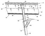
- FIG. 1is a rear perspective view of a merchandising system including a track mounted on a front rail, in accordance with a first embodiment of the present disclosure
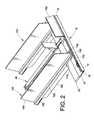
- FIG. 2is a reduced front perspective view of the merchandising system of FIG. 1 , also including a pair of dividers and a front fence;
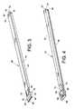
- FIG. 3is a top side perspective view of the track of FIG. 1 ;
- FIG. 4is a bottom side perspective view of the track of FIG. 1 ;
- FIG. 5is an enlarged rear perspective view of a pusher mounted on the track of FIG. 1 ;
- FIG. 6is a front perspective view of the pusher of FIG. 5 ;
- FIG. 7is a reduced bottom plan view of the pusher of FIG. 5 ;
- FIG. 8is a rear elevational view, in partial cross section, of the merchandising system of FIG. 1 ;
- FIG. 9is a reduced side elevational view, in cross section, of the merchandising system of FIG. 1 ;
- FIG. 10is a rear perspective view of a front rail according to a second embodiment of the present invention.
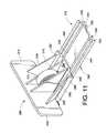
- FIG. 11is a rear perspective view of a short track which can be accommodated on the front rail of FIG. 10 ;
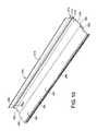
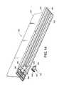
- FIG. 12is a bottom perspective view of an elongated track which can be accommodated on the front rail of FIG. 10 ;
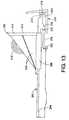
- FIG. 13is a side elevational view of the track of FIG. 11 assembled on the front rail of FIG. 10 ;
- FIG. 14is a bottom perspective view of a divider which cooperates with the front rail of FIG. 10 ;
- FIG. 15is an enlarged bottom perspective view of a front portion of the divider of FIG. 14 with the remainder thereof broken away;
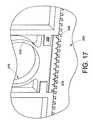
- FIG. 16is a side elevational view of the divider of FIG. 14 assembled on the front rail of FIG. 10 ;
- FIG. 17is a greatly enlarged bottom perspective view of a portion of the front rail and divider of FIG. 16 ;
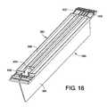
- FIG. 18is a bottom perspective view of a divider according to a third embodiment of the present invention.
- FIG. 19is a top perspective view of a track according to a third embodiment of the present invention.
- FIG. 20is a perspective view of a pusher meant to be accommodated on the track of FIG. 19 ;
- FIG. 21is a rear perspective view of the track of FIG. 19 with the pusher of FIG. 20 mounted on the track;
- FIG. 22is a top perspective view of a shelf management system according to a fourth embodiment of the present invention, including a front rail, several tracks and several dividers;
- FIG. 23Ais a rear perspective view of a front portion of the shelf management system of FIG. 22 illustrating only the front rail and a section of a track;
- FIG. 23Bis a greatly enlarged cross-sectional view of a locking element employed with the track of FIG. 23 a;
- FIG. 24Ais a perspective view of the front rail and track of FIG. 23A , enlarged and partially broken away, with the locking element in a first position, locking the track to the front rail;
- FIG. 24Billustrates the locking element of FIG. 24A in a second position, allowing the track to move in relation to the front rail;
- FIG. 25is a front perspective view of a merchandising system according to a fifth embodiment of the present invention, including a front rail, a track and a pair of dividers;
- FIG. 26is an enlarged rear perspective view of a portion of the merchandising system of FIG. 25 ;
- FIG. 27is an enlarged partially broken away bottom perspective view of the track and the front rail of FIG. 26 , showing a locking engagement to prevent movement of the track in relation to the front rail;
- FIG. 28is a broken away and enlarged view of a portion of the divider and front rail of FIG. 26 showing a locking engagement to prevent movement of the divider in relation to the front rail;
- FIG. 29is a perspective view of a sixth embodiment of a track according to the present disclosure.
- FIG. 30is a perspective view of a seventh embodiment of a track according to the present disclosure.
- FIG. 31is a bottom plan view of a cooperating member according to yet another embodiment of the present disclosure.
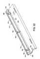
- FIG. 32is a bottom perspective view of the mounting member according to still another embodiment of the present disclosure, in a first position
- FIG. 33is a bottom perspective view of the mounting member of FIG. 32 in a second position
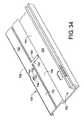
- FIG. 34is a top perspective view of a mounting member according to yet a further embodiment of the present disclosure in a first position.
- FIG. 35is a bottom perspective view of the mounting member of FIG. 34 .
- FIG. 1illustrates a first embodiment of a merchandising system according to the present disclosure.
- an elongated mounting member or front rail 10includes a vertically oriented wall 12 , which comprises a first section 14 , a groove 16 and a second section 18 .
- a horizontally oriented wall 20is also provided on the mounting member 10 .
- a second groove 22Disposed in the horizontally oriented wall is a second groove 22 .
- An aperture 28positioned in the second groove 22 , extends through the horizontally oriented wall 20 .
- a suitable conventional fastener(not illustrated) can extend through the opening 28 so as to secure the mounting member in place on a subjacent shelf (not illustrated).
- a suitable conventional fastener(not illustrated) can extend through the opening 28 so as to secure the mounting member in place on a subjacent shelf (not illustrated).
- the horizontally oriented wall 20comprises the second groove 22 , and a plateau-like section which includes a front face 30 , a top face 32 and a back face 34 . Located on the back face are a plurality of spaced teeth 36 .
- a cooperating member, such as a pusher track 40is selectively mounted on the front rail 10 .
- the track 40includes an elongated track body 42 .
- the track body 42is solid in cross section.
- the trackis solid in longitudinal section, along a longitudinal axis thereof. Having a solid rail is advantageous for a number of reasons. First, it makes the molding process for making the rail—from a suitable known thermoplastic material—easier than molding conventional tracks, which require a more complicated die.
- the trackis solid, rather than being hollow with cross braces, it can be made from a less expensive thermoplastic material than used for conventional tracks. Conventional track designs require a more rigid and hence more expensive thermoplastic material.
- the trackcan be made via a gas-assisted injection molding process, in which a certain proportion of the thermoplastic material of the track is replaced by gas. Since less material is used, the cost of the track is reduced somewhat. Such a process allows the part to be somewhat lighter, while still preserving its inherent strength. With this design, the track also has a relatively lower coefficient of friction. The coefficient of friction of such a track is reduced somewhat because of the more porous track surface resulting from the gas-assisted injection molding process. With a more porous surface, there is less surface contact between the track on the one hand and merchandise or a pusher paddle on the other hand. Thus, merchandise supported by the track can more easily slide on the track, as can a pusher paddle.
- the trackincludes a front end 50 , which comprises a mounting head 52 .
- the mounting headincludes a front face 54 . Protruding from the front face is a forwardly extending lip 56 . As best seen in FIG. 1 , the lip 56 is meant to engage the second section 18 of the front rail vertically oriented wall so as to correctly locate or position the track on the front rail and prevent any looseness or wobbling in the engagement between the track and the front rail.
- the mounting head 52also includes a top face 60 .
- An aperture 62extends through the top face, as is evident from a comparison of FIGS. 3 and 4 .
- the mounting headalso includes a first side wall 64 , a second side wall 66 and a rear wall 68 . Depending from the rear wall is a projection 70 .
- Located in the pusher track 40 behind the mounting head 52is a cross slot 74 , as best seen in FIG. 4 .
- the cross slotis meant to accommodate the plateau-like portion of the front rail, as is evident from FIGS. 1 and 2 .
- the pusher trackincludes a rear end 80 .
- a vertically oriented slot 82Extending through the rear end is a vertically oriented slot 82 .
- the slot 82thus divides the track rear end into two portions or defines extensions 83 and 84 .
- Such extensionsallow the track rear end to be flexible, in relation to the remainder of the track.
- first and second teeth 85 and 86Located on opposed side faces of the track body 42 , adjacent the slot 82 , are first and second teeth 85 and 86 .
- the teethcan be located directly beneath the first and second rails 44 and 46 .
- a pusher 90is adapted to be mounted on the pusher track 40 .
- the pusher 90includes a base 92 .
- the basecomprises a top wall 94 , a first side wall 96 and a second side wall 98 ( FIG. 6 ).
- an inverted channel-like configurationis defined.
- a first flange 100extends from the first side wall 96 and a second flange 102 extends from the second side wall 98 .
- a first groove 104is defined in the first side wall 96 and the second groove 106 is defined in the second side wall.
- a paddle 110is mounted on the base 92 .
- FIG. 6shows that the paddle includes a front face 112 .
- the paddlealso includes a rear face 114 .
- Supporting the rear faceare first and second gussets 116 and 118 , which extend from the paddle rear face to the base top wall 94 .
- the gussetsreinforce the pusher 90 and prevent the paddle 110 from buckling.
- a support wall 122is disposed between the pair of gussets, in a manner spaced from the pusher base top wall 94 .
- a suitable coil spring 126is mounted on the support wall 122 . As best shown in FIG.
- the coil springhas a front portion 128 and a front end 130 .
- the coil spring front endincludes a bent portion (not visible) which extends into the aperture 62 in the pusher track and engages the track to retain the spring in place. This is conventional in the art.
- the merchandisesits on the forward portion 128 of the coil spring.
- the springsince it is made from a suitable conventional metal, is inherently somewhat more slippery than the material of the track. Since the coil spring sits directly on the track, the merchandise sits on the coil spring and, thus, can slide more easily than if it sat directly on the track.
- ribs(not shown) could be provided laterally on both sides of the coil spring so as to further reduce frictional contact between the track and merchandise supported on the track.
- the two portions or extensions 83 and 84 of the track body rear end 80are pushed towards each other. Due to the resilient and flexible nature of the thermoplastic material from which the track body is made, and due to the presence of the vertical slot 82 , a width of the track rear end can be reduced so as to allow the pusher base to be mounted on the pusher track.
- the rear end portions 83 and 84return to their normal orientation because of the inherent resiliency of the material from which the track is made.
- the first and second rails 44 and 46 of the pusher trackare accommodated in the first and second grooves 104 and 106 defined in the base 92 of the pusher 90 . Therefore, the pusher 90 is allowed to reciprocate on the track 40 . Also, the pusher is urged in a forward direction by the coil spring 126 .
- the teeth 85 and 86 at the rear end of the pusher track 40prevent the pusher 90 from sliding off the track at the rear end thereof. More particularly, the side walls 96 and 98 of the pusher engage the teeth 85 and 86 to prevent the pusher from being slid off the track.
- a merchantsimply needs to press the two portions 83 and 84 of the track rear end towards each other so as to allow the pusher to clear the teeth.
- the pusher track mounting head 52is larger in width than is the remainder of the pusher track. This serves several purposes.
- the wider mounting head 52 on the pusher track 40prevents engagement between adjacent pushers mounted on adjacent tracks. Such engagement is disadvantageous as it would retard the ability of the pusher to slide forward and rearward on the track.
- the relative width of the mounting head 60is such that it is at least as wide as a cross section taken through the pusher track and the pusher, at the location of the pusher 90 . This cross sectional relationship prevents the pusher from getting hung up on an adjacent pusher track or being inadvertently moved, when it is located next to another pusher on an adjacent pusher track.
- a divider 150includes a base 152 and an upright wall 154 protruding from the base.
- the upright wallcan separate the base into a first section 156 and a second section 158 .
- Located adjacent a front end of the baseis a projection 172 .
- Located rearwardly of the projectionis a cross slot 174 .
- the cross slotis meant to accommodate the plateau-like raised section of the front rail horizontally oriented wall.
- a side wing 180is located on one side of the base 152 . For narrow products, such as, e.g., a row of tooth brushes, the wing 180 can be broken off from the divider base along a break line or weakened line 182 .
- a front fence 188can be inserted in the slot 16 located between the first and second sections 14 and 18 of the front rail vertical wall 12 .
- the front fencecan be made from a transparent material, so that the merchandise being displayed on the shelf (not illustrated) is visible to the customer.
- a second embodiment of the merchandising systemincludes an elongated mounting member, such as a front rail 210 , which includes a vertically oriented wall 212 , which, in turn, comprises a first section 214 , a groove 216 and a second section 218 .
- a front fence 219can be mounted in the groove 216 .
- Also provided on the front rail or mounting member 210is a horizontally oriented wall 220 .
- a second groove 222Disposed in the horizontally oriented wall is a second groove 222 .
- An aperture 228is positioned in the second groove 222 , and extends through the horizontally oriented wall 220 .
- a suitable conventional fastener(not illustrated) can extend through the opening 228 so as to secure the front rail in place on a shelf.
- the horizontally oriented wall 220also comprises a plateau-like section 224 which includes a front face 230 , a top face 232 and a back face 234 . Located on the back face are a plurality of spaced protrusions, which can be teeth 236 .
- a cooperating membersuch as a pusher track 240 is selectively mounted on or to the front rail 210 .
- the track 240can include an elongated track body 242 , of any desired length. Defined thereon are a pair of oppositely extending rails 244 and 246 .
- the trackalso includes a recessed central section 248 , as can best be seen in FIG. 11 . Such recessed area 248 is defined in a horizontal wall 250 of the track 240 .
- first, second, third and fourth reinforcing ribs 252 - 258depending from the horizontal wall 250 are first, second, third and fourth reinforcing ribs 252 - 258 .
- the four reinforcing ribsare spaced from each other.
- Extending between the two inner reinforcing ribs 254 and 256are a series of stiffening elements 260 . These can be arranged in zigzag fashion, in order to provide additional strength or stiffness to the track 240 .
- grooves(unnumbered) are defined between the first and second stiffening ribs 252 and 254 , as well as between the third and fourth stiffening ribs 256 and 258 . In other words, no stiffening elements are located in these grooves.
- the track 240can be injection molded from a suitable known material, such as a thermoplastic material.
- the trackalso includes a front end 270 which extends forward of the reinforcing ribs 252 - 258 , as well as the stiffening elements 260 .
- a tongue 272Protruding from the front end 270 is a tongue 272 .
- the tongue 272contacts the rail vertically oriented wall second section 218 in order to correctly align the track with the rail and in order to prevent any looseness or wobbling of the track in relation to the rail.
- a traverse slot 274defined on a bottom side of the track.
- the slotis defined on a front side by a pair of depending flanges 276 and 278 , separated by a gap 280 . It is defined on a rear side by a wall 282 which serves as the forward terminus of the four stiffening ribs 254 - 258 .
- a respective tooth 284can be located at a rear end of each of the rails 244 and 246 . Only one of the teeth is visible in FIG. 12 .
- the purpose for the teethis to prevent a pusher 290 from being retracted so far that it falls off the track.
- the pusher 290includes a base 292 which will contact the teeth 284 .
- the base 292includes a top wall 294 which can be recessed so as to be correctly accommodated on the track 240 .
- the basealso includes first and second sidewalls 296 and 298 , as well as respective flanges extending inwardly therefrom. Only one such flange 300 is visible in FIG. 11 . In other words, the base 292 wraps around the rails 244 and 246 located on the track 240 .
- a paddle 310Supported on the base is a paddle 310 . Included on the paddle is a front face 312 ( FIG. 13 ) and a rear face 314 ( FIG. 11 ). Unlike the paddle embodiment illustrated in FIG. 8 , the paddle 310 shown in FIG. 11 is considerably wider than is the width of its track 240 . For example, the paddle can be approximately twice as wide as the track. In this way, the paddle can accommodate wide merchandise, such as, for example, frozen TV dinners or the like. Of course, it should be appreciated that the paddle can have any desired shape and width depending upon the merchandise which is meant to be urged forwardly on the track. Supporting the rear face are a plurality of gussets 316 .
- the plurality of gussetsare so arranged that the two outermost gussets are angled outwardly in order to better support the paddle 310 on the base 292 .
- Disposed between the inner two gussetsis a coil spring 318 .
- the coil springwill bias the pusher 290 forwardly on the track 240 .
- the pair of spaced flanges 276 and 278will contact the front face 230 of the plateau-like section 224 and the slot 274 on the track 240 accommodates the plateau-like section.
- the forward wall 282 of the trackis spaced from the teeth 236 defined on the back face 234 of the plateau-like section 224 so as to not interfere therewith.
- the forwardly extending lip 272 defined on the front end 270 of the track 240will contact the second section 218 of the vertically oriented wall 212 of the front rail 210 . However, this contact will be above the second groove 222 which is defined in the front rail 210 .
- the track 240is slidable laterally or sideways in relation to the track 210 .
- disengagement of the track from the front railcan be achieved without having to slide the track sideways until it is detached from the front rail.
- one can twist the track about its longitudinal axis in a first directionsuch that a first one of the flanges 276 and 278 is disengaged from its contact with the plateau-like section 224 and then twist it in an opposite, second direction until the other flange is disengaged.
- Thiscan be accomplished due to the inherent resiliency of the thermoplastic material from which the track 240 is made.
- the front rail 210can be made from a similar thermoplastic material, so that both the front rail and the track can have some “give”.
- a cooperating membersuch as a divider 330 can also be employed with the front rail 210 , as is there illustrated.
- the dividerincludes a base 332 and, extending upwardly therefrom, a vertical wall 334 .
- the vertical wallcan divide the base into opposed sections.
- the baseitself is defined by a horizontal wall 336 and, depending therefrom, a plurality of reinforcing ribs 338 . These can best be seen in FIG. 15 . Five such reinforcing ribs are illustrated in the embodiment of FIGS. 14 and 15 . Of course, any suitable number can be employed.
- a solid basecan be employed, as shown for the track in FIGS. 8 and 9 .
- the reinforcing ribsterminate at a transverse slot 340 defined in a bottom face of the divider 330 .
- the transverse slotcomprises a rear wall 342 at which all of the reinforcing ribs 338 terminate, as well as a front wall 334 .
- suitable reinforcing walls 346can be provided in the slot so as to stiffen the divider 330 in that area.
- a front face 348is also provided on the divider.
- a chamber 350Defined in the base is a chamber 350 .
- the three central walls 338define the chamber 350 .
- the chambercomprises a rear wall 352 and a pair of side walls 354 .
- a protrusion 356extends into the chamber from the rear wall.
- Also extending above the chamber from the side walls 354are a pair of flanges 358 .
- Selectively mounted in the chamber 350is an engaging element 370 .
- the engaging elementcomprises a face 372 on which are defined a plurality of spaced protrusions 374 .
- the engaging elementalso comprises a biasing member 376 .
- a clip 378located on the biasing member, enables the engaging element to be selectively mounted on the protrusion 356 extending into the chamber 350 , as is evident from FIG. 15 .
- the engaging element 370can be detached from the divider 330 when so desired.
- the divider 330is mounted on the front rail 210 .
- the transverse slot 340accommodates the plateau-like section 224 of the front rail.
- the front wall 334 of the transverse slot 340contacts the front face 230 of the plateau-like section 224 .
- the rear wall 342contacts the back face 334 of the plateau-like section 224 .
- the front face 348 of the divideris spaced from the second section 218 of the front rail vertically oriented wall 212 .
- FIG. 17it can be seen that the engaging element 370 contacts the plateau-like section 224 of the front rail.
- the protrusions 374 of the engaging element 370engage the teeth 236 defined on the back face 234 of the front rail plateau-like section 224 .
- the rail 210 and divider 33are selectively attached, fixed, connected, joined or secured to each other, in a way to retard relative movement between them.
- protrusions 374 and teeth 236any suitable types of engaging elements can be employed for this purpose.
- these two elementscan have the same shape, if so desired.
- the rounded shapes of the protrusions 374allow the divider 330 to ratchet in relation to the front rail 220 when the rear end of the divider is lifted, even a slight amount.
- the dividercan be moved without completely retracting the engaging element from contact with the teeth 236 .
- the biasing member 376allows the engaging element 370 to be resiliently biased into contact with the front rail teeth 236 , due to the inherent resilient nature of the thermoplastic material from which the engaging element can be made.
- the engaging elementcould also be made from other suitable materials, such as various metals or the like. It should thus be appreciated that the engaging element could be made from a different material than the cooperating member or the mounting member. In addition, various sections of the engaging element could be made from different materials, if so desired.
- the biasing member 376could be made from a more resilient material than the face 372 .
- the purpose for the flanges 358is to prevent the engaging element 370 from falling out of the chamber 350 . They also provide guidance for the movement of the engaging element 370 as it reciprocates due to the inherent resiliency of the biasing member 376 . Such reciprocation occurs when the divider 330 is detached from and attached to the front rail 210 . As noted, this can be accomplished by simply pivoting the rear end of the divider in an upward direction. Depending on the degree of pivoting, such action can disengage the protrusions 374 and the teeth 236 . Alternatively, depending on the shapes of the protrusions and teeth, it can allow a relative movement between them, even when they are contacting each other.
- a divider 390is there illustrated.
- the divideris provided with a base 392 and a vertical wall 394 extending upwardly from the base.
- a plurality of reinforcing ribscan depend from the base.
- a first transverse slot 400 and a second transverse slot 402are located on opposed ends of the base.
- the first transverse slotincludes a chamber 404 for selectively accommodating an engaging element, such as the engaging element 370 illustrated in FIG. 14 .
- the second transverse slotincludes a plurality of protrusions 406 .
- the dividercan either lock against the front rail or be continuously slidable in relation to the front rail.
- FIG. 19another type of track 410 is there illustrated.
- This trackis similar to track 40 illustrated in FIG. 3 . It includes a pair of rails 412 (see also FIG. 21 ) and a front end 414 which is provided with a tongue or protrusion 416 .
- the tongue 416is not movable in relation to the front end, unlike the tongue 56 illustrated in FIG. 3 .
- Slidably mounted on the track 410is a pusher 420 .
- the pusher 420can reciprocate on the track 410 .
- the pusherincludes a base 422 which is provided with a first side wall 424 and a second side wall 426 . Each of these has a respective groove 428 and 430 therein for accommodating the rails 412 of the track 410 .
- FIG. 22another embodiment of a merchandising system 438 is there illustrated.
- This embodimentincludes a mounting member in the form of a front rail 440 , one or more tracks 442 and one or more dividers 444 .
- An end wall 446can also be provided.
- the track 442includes a pair of rails 450 and 452 .
- the railsextend from a base 454 of the track.
- the track baseincludes a front portion 456 .
- Pivotally mounted in a slot 458 defined in the front portion 456is a locking element 460 .
- the locking element 460includes a pivot section 462 , as well as first and second stems 464 and 466 .
- the locking element 460can be pivoted around the pivot section 462 so as to assume either the locked position, illustrated in FIG. 24A , or the unlocked position, illustrated in FIG. 24B .
- the locking element 460In the unlocked position, the locking element 460 is pivoted so that the first stem 464 is pushed down at contact surface 468 and approaches a base wall 470 defined in a groove 472 in the front rail 440 .
- the first stem 464contacts the groove 472 (see FIG. 24B ) in order to limit the rotation of the locking element 460 .
- the second stem 466which can also be termed a locking stem, is withdrawn from its locked position in an aperture 476 in a plateau section 478 of the front rail 440 .
- the trackcan be slid laterally on the front rail 440 .
- the locking element 460can be released. This allows the locking stem 466 to enter the subjacent aperture 476 thereby locking the track at the desired location along the length of the front rail 440 .
- the trackcan be locked to the rail at a number of discrete positions.
- the locking elementis biased into the locked position around the pivot 462 . This can be accomplished by the inherent resiliency of the thermoplastic material from which the locking element 460 can be made. In other words, the locking element can be rotated around the pivot section 462 , but when finger pressure is released from the locking element, i.e., the person's digit is withdrawn from the contact surface 468 , the locking element will return to its unbiased condition illustrated in FIG. 24A .
- the dividers 446can be provided with a similar locking arrangement, including locking elements 480 mounted in a front section 482 of a base portion 484 of the divider 444 .
- the locking elements 480can function in the same manner as outlined above for the locking element 460 mounted on the track 442 .
- the end wall 446can be provided with a similar locking element.
- a front rail 490accommodates one or more tracks 492 and one or more dividers 494 .
- the front railcan be mounted to a base section 496 which, in turn, is connected to a rear rail 498 .
- both the divider and the trackinclude engaging elements which selectively contact a suitably shaped engagement surface on the front rail.
- teeth 502are provided on the front rail.
- the teeth 502selectively engage mating engagement elements, such as teeth 504 provided on a moveable engaging member 506 which can be mounted for a reciprocation on a base 508 of the track 492 .
- a biasing member 510extends from a rear surface of the engaging member 506 .
- the biasing memberpushes against a cross bar 514 provided on a bottom surface of the base 508 in order to push the engaging member teeth 504 into mating engagement with the mounting member teeth 502 .
- the engaging member 506is held between a pair of longitudinally extending reinforcing ribs mounted on the base 508 .
- the baseincludes a pair of rails 518 for slidably mounting a pusher 520 .
- FIG. 26illustrates that an opening 524 can be located in the base 508 .
- the openingenables finger access to a contact surface 526 of the engaging member 506 so that the engaging member can be retracted.
- Such retraction, against the bias of the biasing member 510disengages the teeth 504 of the engaging member 506 from the teeth 502 of the rail.
- the track 492can be moved laterally, such as by sliding, in relation to the front rail 490 . In this way, the track can be moved laterally without having to be unloaded. Put another way, the track can be laterally adjusted even though merchandise is supported on the track when the track is slid laterally. It should be appreciated that the track 492 cannot be pivoted in this embodiment.
- the divider 494includes a base portion 530 , as well as an upstanding divider member 532 .
- the engaging memberincludes, on the front end, a set of teeth 536 . These teeth selectively engage the teeth 502 of the front rail.
- the engaging memberalso includes a body portion. Located on a rear end of the engaging member is a biasing member 540 . As with the biasing member of FIG. 27 , the biasing member 540 urges the engaging member 534 forwardly so as to bring the teeth 536 thereof into engagement with the teeth 502 of the front rail.
- the biasing member 540can rest against a cross bar 542 located on the base 530 .
- a pair of apertures 546are located in the base (only one of the apertures being visible in FIG. 26 ).
- Respective contact surfaces 548are accessible from the top surface of the base 530 .
- a track 560is provided with a blocking element 562 for selectively limiting the extent to which a pusher member 564 can be retracted on the track 560 .
- a base 570 of the trackis provided with a longitudinally extending groove 572 for accommodating the blocking element 562 .
- the blocking element 562can be provided with a head portion 574 which extends at, for example, a right angle to a body portion 576 of the blocking element. Spaced along the body portion are a series of serrations 578 . When the blocking element is located to the correct orientation, the serrations can be selectively engaged by a ratchet member 580 .
- the pusher base 570can be provided with one or more apertures 590 , into a selected one of which a pin 592 can be placed.
- the purpose for the pinis to prevent the pusher 564 from being retracted past a given point along the length of the track 560 . This would be advantageous in a merchandise setting where high value merchandise is being displayed on the track, and the merchant wishes to limit the number of items stored on the track at any given time. If there are only a few high value items located on the track, then pilferage of such high value items may be retarded, since a thief can only obtain a limited number of the high value items at any given time. In any case, only a limited number of such items would be lost.
- a further embodiment of a track 600includes a cross slot 602 and a cooperating member 604 .
- the cooperating memberhas a face with a plurality of protrusions 606 which extend into the slot 602 .
- a resilient biasing member 608urges the protrusion 606 into the slot 602 .
- a trackis provided with an engaging element which is moveable in relation to the track. The engaging element selectively contacts the protrusions or teeth on the plateau of an elongated mounting member such as a front rail of the type discussed previously herein. In this way, a track can be selectively secured to such a rail so as to retard relative movement therebetween.
- a cooperating member 618can include an engaging element 620 with one or more protrusions 622 extending therefrom into a slot 624 defined in the cooperating member.
- the engaging elementcan be biased by a resilient biasing member such as at 626 .
- a limiting member 630is provided.
- the limiting memberselectively limits the resiliency of the biasing member and thus assists in holding engaging element in a desired condition. More particularly, the limiting member 630 is moveable between discrete positions.
- the biasing member 626can be provided with small protrusions 632 in order to maintain the limiting member in a selected angular orientation. Three such orientations, spaced apart at 45° angles, are illustrated in FIG. 31 .
- the biasing memberIn a first orientation shown in solid lines, the biasing member is allowed to flex an intermediate amount. In a second, locked condition the limiting member is oriented approximately perpendicular to a face of the engaging element 620 . In this orientation, the limiting member 630 prevents any flexing of the resilient member 626 , thereby locking the cooperating member to the elongated mounting member. In a third orientation, in which the limiting member is oriented parallel to the face of the engaging element, the biasing member 626 is allowed to flex to its full extent, thereby providing a low or no ratchet condition for the engaging element in relation to the elongated mounting member. Thus, the amount of bias provided by the biasing element 626 can be controlled in order to selectively lock the cooperating member to the elongated mounting member. Alternatively, the engaging element can be simply resiliently biased into engagement with the elongated mounting member.
- FIGS. 32 and 33illustrate another embodiment of a mounting member according to the present disclosure.
- the mounting member 650includes a bottom surface 652 .
- a channel 654is defined in the bottom surface at the location of a plateau 656 defined on the mounting member.
- an engaging element 670is also provided in this embodiment.
- the engaging elementincludes a top wall 672 and a rear wall 674 . Defined on the rear wall are a plurality of protrusions 676 .
- a connecting system 680connects the engaging element 670 to the mounting member 650 in a moveable manner. More particularly, in this embodiment, the connecting system includes a first link 682 , a second link 684 and a third link 686 .
- respective stubs 690 on the mounting member and 692 on the engaging elementare provided.
- the linksare able to rotate in relation to the stubs and, hence, allow a movement of the engaging element 670 in relation to the mounting member 650 as is evident from a comparison of FIGS. 32 and 33 .
- a handle portion 696is provided on the third link 686 . The handle portion is accessible from beneath the engaging element so that it can be manually moved by store personnel when that is considered desirable.
- the mounting memberincludes a horizontal wall 702 in which is defined a channel 704 and a plateau section 706 .
- the engaging elementincludes a top wall 722 and a rear wall 724 on which there are defined a plurality of protrusions 726 .
- a connecting system 730connects the engaging element 720 to the mounting member 700 .
- the connecting system 730includes a cam 732 rotatably mounted on the engaging element and a cam surface 734 defined on the mounting member. More particularly, the cam surface 734 is defined on a bottom face 736 of the plateau section 706 .
- a knob 746is accessible from a top side of the plateau 706 as it extends through an aperture 748 therein.
- a rotation of the knob 746causes a rotation of the cam 732 against the cam surface 734 thereby moving the engaging element linearly forwards and backwards in relation to the mounting member 700 .
- the engaging elementcan be provided with one or more protrusions 750 which extend into slots 752 defined in the plateau 706 of the mounting member 700 .
- a means for selectively locking the cooperating memberi.e., a track, a divider or a combination track and divider, to a mounting member, such as a rail, in order to hinder the tendency for dividers to “walk” in relation to the mounting member when cylindrical items, such as cans or bottles, are pushed forward on a track.
- the resilient engaging elements discussed hereinenable the cooperating member to sufficiently engage the mounting member with just the right amount of fit. Since the mounting members and the cooperating members are normally made from a thermoplastic material, there is some variation in tolerances which needs to be accommodated.
- the instant engaging element which is resiliently biasedhas benefit in that the cooperating member engages the mounting member in a way which is not too tight and not too loose. If the cooperating member is too loosely engaged on the mounting member due to tolerance variances, then the cooperating member can move too easily in relation to the mounting member. This has the disadvantages mentioned previously.
- the elongated mounting memberhas been described as a front rail, it should be appreciated that the rail could be otherwise located on a shelf.
- a rear railcould be employed instead of a front rail.
- both front and rear railscan be used, as shown in FIG. 25 .
- the engaging element of the cooperating membercan have any desired shape so as to selectively secure the cooperating member to the mounting member.
- protrusions and stemshave been disclosed for contacting, cooperating with or engaging with teeth and apertures, respectively, other types of known cooperating surfaces could be employed instead.
- the cooperating memberhas been illustrated as a divider in several figures (for example, FIGS. 14-18 ) and as a track in other figures (for example, FIGS. 3 , 4 , 11 - 13 , 19 , 24 A and 29 ).
- the track and dividerhave been shown mounted on a mounting member in a side-by-side manner (see, for example, FIGS. 2 , 22 , 25 and 26 ) but spaced from each other. It should be, however, appreciated that the track and divider could be made integral with each other. On such design is shown in U.S. Pat. No. 7,216,770, the disclosure of which is incorporated hereinto, in its entirety.
Landscapes
- Display Racks (AREA)
Abstract
Description
Claims (20)
Priority Applications (1)
| Application Number | Priority Date | Filing Date | Title |
|---|---|---|---|
| US13/400,654US8342340B2 (en) | 2006-02-16 | 2012-02-21 | Merchandising system |
Applications Claiming Priority (3)
| Application Number | Priority Date | Filing Date | Title |
|---|---|---|---|
| US11/356,398US7971735B2 (en) | 2006-02-16 | 2006-02-16 | Merchandising system |
| US11/809,862US8177076B2 (en) | 2006-02-16 | 2007-06-01 | Merchandising system |
| US13/400,654US8342340B2 (en) | 2006-02-16 | 2012-02-21 | Merchandising system |
Related Parent Applications (1)
| Application Number | Title | Priority Date | Filing Date |
|---|---|---|---|
| US11/809,862ContinuationUS8177076B2 (en) | 2006-02-16 | 2007-06-01 | Merchandising system |
Publications (2)
| Publication Number | Publication Date |
|---|---|
| US20120145658A1 US20120145658A1 (en) | 2012-06-14 |
| US8342340B2true US8342340B2 (en) | 2013-01-01 |
Family
ID=46328817
Family Applications (2)
| Application Number | Title | Priority Date | Filing Date |
|---|---|---|---|
| US11/809,862Active2027-03-27US8177076B2 (en) | 2006-02-16 | 2007-06-01 | Merchandising system |
| US13/400,654ActiveUS8342340B2 (en) | 2006-02-16 | 2012-02-21 | Merchandising system |
Family Applications Before (1)
| Application Number | Title | Priority Date | Filing Date |
|---|---|---|---|
| US11/809,862Active2027-03-27US8177076B2 (en) | 2006-02-16 | 2007-06-01 | Merchandising system |
Country Status (1)
| Country | Link |
|---|---|
| US (2) | US8177076B2 (en) |
Cited By (44)
| Publication number | Priority date | Publication date | Assignee | Title |
|---|---|---|---|---|
| US20120006773A1 (en)* | 2006-02-16 | 2012-01-12 | Fasteners For Retail, Inc. | Merchandising system |
| US20140326690A1 (en)* | 2005-09-12 | 2014-11-06 | Rtc Industries, Inc. | Product management display system with trackless pusher mechanism |
| USD723842S1 (en) | 2013-05-02 | 2015-03-10 | Fasteners For Retail, Inc. | Dual end divider |
| US9101231B2 (en) | 2013-04-30 | 2015-08-11 | The Marco Company | Freezer pusher |
| US9101230B2 (en) | 2013-04-30 | 2015-08-11 | The Marco Company | Salad pusher |
| US9173504B2 (en) | 2005-09-12 | 2015-11-03 | Rtc Industries, Inc. | Product management display system |
| US9185999B2 (en) | 2005-09-12 | 2015-11-17 | Rtc Industries, Inc. | Product management display system with trackless pusher mechanism |
| US9232864B2 (en) | 2005-09-12 | 2016-01-12 | RTC Industries, Incorporated | Product management display system with trackless pusher mechanism |
| US9259102B2 (en) | 2005-09-12 | 2016-02-16 | RTC Industries, Incorporated | Product management display system with trackless pusher mechanism |
| US9265362B2 (en) | 2005-09-12 | 2016-02-23 | RTC Industries, Incorporated | Product management display system |
| US9265358B2 (en) | 2005-09-12 | 2016-02-23 | RTC Industries, Incorporated | Product management display system |
| US9289078B2 (en) | 2004-02-03 | 2016-03-22 | Rtc Industries, Inc. | Product securement and management system |
| US9357841B2 (en) | 2013-04-08 | 2016-06-07 | Fasteners For Retail, Inc. | Latch assembly for securing tracks and dividers to a front rail |
| US9402485B2 (en) | 2005-09-12 | 2016-08-02 | Rtc Industries, Inc. | Product management display system with trackless pusher mechanism |
| US20160296039A1 (en)* | 2015-04-08 | 2016-10-13 | Fasteners For Retail, Inc. | Divider with selectively securable track assembly |
| US9486088B2 (en) | 2005-09-12 | 2016-11-08 | Rtc Industries, Inc. | Product management display system |
| US9510677B2 (en) | 2005-09-12 | 2016-12-06 | Rtc Industries, Inc. | Product management display system with rail mounting clip |
| US9532658B2 (en) | 2005-09-12 | 2017-01-03 | Rtc Industries, Inc. | Product management display system |
| US9538860B2 (en) | 2014-09-26 | 2017-01-10 | Fasteners For Retail, Inc. | Selectively locking merchandising member |
| US9706857B2 (en) | 2004-02-03 | 2017-07-18 | Rtc Industries, Inc. | Product securement and management system |
| US9750354B2 (en) | 2005-09-12 | 2017-09-05 | Rtc Industries, Inc. | Product management display system |
| US9770121B2 (en) | 2015-04-08 | 2017-09-26 | Fasteners For Retail, Inc. | Selectively locking merchandising member |
| US9805539B2 (en) | 2004-02-03 | 2017-10-31 | Rtc Industries, Inc. | System for inventory management |
| USD801734S1 (en) | 2014-12-01 | 2017-11-07 | Retail Space Solutions Llc | Shelf management parts |
| US9844280B2 (en) | 2004-02-03 | 2017-12-19 | Rtc Industries, Inc. | Product securement and management system |
| USD825969S1 (en)* | 2016-04-01 | 2018-08-21 | Post Consumer Brands, LLC | Shelf divider for display of bagged food items |
| US10111539B2 (en) | 2016-05-04 | 2018-10-30 | Post Consumer Brands, LLC | Shelf partition for displaying bagged food items and method of using the same |
| US10154739B2 (en) | 2013-12-02 | 2018-12-18 | Retail Space Solutions Llc | Universal merchandiser and methods relating to same |
| US10178909B2 (en) | 2016-01-13 | 2019-01-15 | Rtc Industries, Inc. | Anti-splay device for merchandise display system |
| US10210478B2 (en) | 2004-02-03 | 2019-02-19 | Rtc Industries, Inc. | Continuous display shelf edge label device |
| US10260545B2 (en) | 2013-04-08 | 2019-04-16 | Fasteners For Retail, Inc. | Latch assembly for securing tracks and dividers to a front rail |
| US10285510B2 (en) | 2005-09-12 | 2019-05-14 | Rtc Industries, Inc. | Product management display system |
| US10410277B2 (en) | 2013-03-05 | 2019-09-10 | Rtc Industries, Inc. | In-store item alert architecture |
| US10448756B2 (en) | 2017-06-16 | 2019-10-22 | Rtc Industries, Inc. | Product management display system with trackless pusher mechanism |
| US10952546B2 (en) | 2005-09-12 | 2021-03-23 | Rtc Industries, Inc. | Product management display system with trackless pusher mechanism |
| US10959540B2 (en) | 2016-12-05 | 2021-03-30 | Retail Space Solutions Llc | Shelf management system, components thereof, and related methods |
| US11045017B2 (en) | 2017-04-27 | 2021-06-29 | Retail Space Solutions Llc | Shelf-mounted tray and methods relating to same |
| US11109692B2 (en) | 2014-11-12 | 2021-09-07 | Rtc Industries, Inc. | Systems and methods for merchandizing electronic displays |
| US11182738B2 (en) | 2014-11-12 | 2021-11-23 | Rtc Industries, Inc. | System for inventory management |
| US11259652B2 (en) | 2005-09-12 | 2022-03-01 | Rtc Industries, Inc. | Product management display system |
| US11344138B2 (en) | 2005-09-12 | 2022-05-31 | Rtc Industries, Inc. | Product management display system |
| US11375826B2 (en) | 2004-02-03 | 2022-07-05 | Rtc Industries, Inc. | Product securement and management system |
| US11583109B2 (en) | 2005-09-12 | 2023-02-21 | Rtc Industries, Inc. | Product management display system with trackless pusher mechanism |
| US11832737B2 (en)* | 2019-08-09 | 2023-12-05 | Fasteners For Retail, Inc. | Product pusher assembly |
Families Citing this family (20)
| Publication number | Priority date | Publication date | Assignee | Title |
|---|---|---|---|---|
| US8096427B2 (en) | 2002-05-17 | 2012-01-17 | Rtc Industries, Inc. | Product management display system |
| US8627965B2 (en) | 2001-05-17 | 2014-01-14 | Rtc Industries, Inc. | Multi-component display and merchandise systems |
| US8863963B2 (en) | 2005-09-12 | 2014-10-21 | Rtc Industries, Inc. | Product management display system with trackless pusher mechanism |
| US7823734B2 (en) | 2005-09-12 | 2010-11-02 | Rtc Industries, Inc. | Product management display system with trackless pusher mechanism |
| US8453850B2 (en) | 2005-09-12 | 2013-06-04 | Rtc Industries, Inc. | Product management display system with trackless pusher mechanism |
| US7971735B2 (en)* | 2006-02-16 | 2011-07-05 | Fasteners For Retail, Inc. | Merchandising system |
| US8113360B2 (en)* | 2006-05-04 | 2012-02-14 | Carl Olson | Product shelf divider system and method |
| WO2010039973A1 (en)* | 2008-10-01 | 2010-04-08 | Adco Industries-Technologies, L.P. | Shelving glide |
| US8276766B2 (en)* | 2008-10-09 | 2012-10-02 | Fasteners For Retail, Inc. | Adjustable depth merchandising apparatus |
| US8267258B2 (en)* | 2009-04-24 | 2012-09-18 | Xerox Corporation | Tray assembly |
| US8317038B2 (en)* | 2009-11-05 | 2012-11-27 | Henschel-Steinau, Inc. | Modular display and dispensing apparatus with plural dispensing tiers |
| PL2946698T3 (en)* | 2011-09-02 | 2018-03-30 | Rtc Ind Inc | Merchandise display system |
| US20140263134A1 (en)* | 2013-03-14 | 2014-09-18 | Fasteners For Retail, Inc. | Dual end divider |
| BR112015023521B1 (en)* | 2013-03-15 | 2021-12-21 | Rtc Industries, Inc. | MERCHANDISE DISPLAY SYSTEM |
| DE102013111933A1 (en)* | 2013-10-30 | 2015-04-30 | Krones Ag | Container treatment plant and method for adjusting a valve or a discharge device of a container treatment plant |
| US9320367B2 (en) | 2014-02-26 | 2016-04-26 | Southern Imperial, Inc. | Snap-in pusher |
| GB2551136B (en)* | 2016-06-06 | 2019-10-23 | Display By Design Ltd | Modular pusher system |
| US10667629B2 (en)* | 2018-10-05 | 2020-06-02 | Fasteners For Retail, Inc. | Product pusher assembly |
| US20210137265A1 (en)* | 2019-11-11 | 2021-05-13 | Fasteners For Retail, Inc. | Product Divider Assembly |
| AU2024213503A1 (en)* | 2023-02-03 | 2025-07-31 | Fasteners For Retail, Inc. | Selectively securable roller track |
Citations (78)
| Publication number | Priority date | Publication date | Assignee | Title |
|---|---|---|---|---|
| US1971749A (en) | 1931-12-11 | 1934-08-28 | Hamilton Mfg Co | Type case |
| US2079754A (en) | 1935-07-17 | 1937-05-11 | William V Waxgiser | Article projection apparatus for shelves |
| US2652154A (en) | 1949-12-27 | 1953-09-15 | John F Mccarthy | Display rack |
| US2678045A (en) | 1952-04-15 | 1954-05-11 | Frances C Erhard | Card sorting device |
| US3038067A (en) | 1956-05-31 | 1962-06-05 | Raytheon Co | Electrical tuning systems with traveling wave tube |
| US3161295A (en) | 1963-01-24 | 1964-12-15 | Chesley Ind Inc | Display device for merchandise |
| CH412251A (en) | 1964-01-06 | 1966-04-30 | Gemperle Albert | Display and sales shelf with dividing and feeding device |
| US3308961A (en) | 1965-03-03 | 1967-03-14 | Chesley Ind Inc | Package display-dispenser |
| US3452899A (en) | 1967-10-24 | 1969-07-01 | Albert C Libberton | Follower advanced commodity dispenser |
| US3751129A (en) | 1971-10-20 | 1973-08-07 | Wright Barry Corp | Card tray |
| US3814490A (en) | 1972-10-12 | 1974-06-04 | Wright Barry Corp | File drawer follower block |
| US3868021A (en) | 1973-10-09 | 1975-02-25 | Wilhelm Heinrich | Separator panel holder for display shelves |
| US4042096A (en) | 1976-03-15 | 1977-08-16 | Smith Daniel F | Shelf aid |
| US4106668A (en) | 1977-02-14 | 1978-08-15 | Kayser-Roth Corporation | Device for displaying and storing articles |
| DE2825724A1 (en) | 1978-06-12 | 1979-12-13 | Kurt Baumann | Merchandise display unit for upright packages - contains support elements formed from single length of wire |
| GB2027339A (en) | 1978-07-14 | 1980-02-20 | Corjon J L | Racks for dispensing articles |
| US4269326A (en) | 1978-04-17 | 1981-05-26 | Klaus Delbrouck | Dispensing compartment, in particular for refrigerating units |
| US4303162A (en) | 1979-08-13 | 1981-12-01 | The Mead Corporation | Forward feed merchandising device for soft drink bottles |
| US4351439A (en) | 1980-03-11 | 1982-09-28 | Leggett & Platt, Incorporated | Merchandise display device |
| US4378872A (en) | 1977-03-28 | 1983-04-05 | Si Handling Systems, Inc. | Article handling apparatus |
| FR2526338A1 (en) | 1982-05-06 | 1983-11-10 | Corjon Jean Louis | Frame for display and distribution of cigarette packets - has frame with longitudinally sliding rod to dispense packets |
| JPS59218113A (en) | 1983-05-26 | 1984-12-08 | トーイン株式会社 | Commodity display case |
| US4488653A (en) | 1984-03-12 | 1984-12-18 | Paul Belokin | Magnetically mounted shelf divider |
| US4615276A (en) | 1985-09-16 | 1986-10-07 | Garabedian Aram G | Shelf divider assembly |
| US4724968A (en) | 1985-11-16 | 1988-02-16 | Henkel Kommanditgesellschaft Auf Aktien | Device for the presentation of retail articles |
| US4730741A (en) | 1986-10-16 | 1988-03-15 | The Niven Marketing Group | Pressure-feed tray system |
| EP0270016A2 (en) | 1986-11-29 | 1988-06-08 | Werner Schenk | Construction kit for a goods display box |
| US4762236A (en) | 1986-10-16 | 1988-08-09 | The Niven Marketing Group | Adjustable tray dispensing apparatus |
| US4775058A (en) | 1986-12-15 | 1988-10-04 | Jameson Pharmaceutical Corp. | Display shelf organizer |
| FR2617385A1 (en) | 1987-07-02 | 1989-01-06 | Normandie Conditionnement | Modular device for displaying and automatically dispensing articles |
| US4830201A (en) | 1988-04-11 | 1989-05-16 | Rtc Industries, Inc. | Spring-urged shelf divider system |
| US4907707A (en) | 1988-04-04 | 1990-03-13 | Oscar Mayer Foods Corporation | Merchandiser assembly |
| US5111942A (en) | 1990-04-25 | 1992-05-12 | Didier Bernardin | Display tray for aligned articles |
| US5161704A (en) | 1991-12-02 | 1992-11-10 | Southern Imperial, Inc. | Shelf divider |
| US5190186A (en) | 1990-04-06 | 1993-03-02 | P.O.P. Displays, Inc. | Multi-package adjustable shelf display dispenser |
| US5203463A (en) | 1991-12-09 | 1993-04-20 | Gold Steven K | Adjustable product display and dispensing unit |
| US5255802A (en) | 1991-03-22 | 1993-10-26 | Padco, Incorporated | Merchandise display system |
| US5325792A (en) | 1992-09-11 | 1994-07-05 | Mulloy Bernard J | Bookshelf with adjustable locking bookends |
| US5341945A (en) | 1993-08-31 | 1994-08-30 | Burke Gibson, Inc. | Shelf divider system |
| US5351839A (en) | 1992-09-28 | 1994-10-04 | Decision Point Marketing, Inc. | Vertically adjustable pusher point of purchase display |
| US5390802A (en) | 1993-02-12 | 1995-02-21 | Hmg Worldwide In-Store Marketing, Inc. | Shelf assembly for gondola display structure |
| US5450969A (en) | 1993-11-08 | 1995-09-19 | Gamon International, Inc. | Shelving display |
| US5469976A (en) | 1993-04-30 | 1995-11-28 | Burchell; James R. | Shelf allocation and management system |
| GB2290077A (en) | 1994-06-10 | 1995-12-13 | Ppe Ltd | Latch for pusher on a merchandising shelf |
| FR2724098A1 (en) | 1994-09-01 | 1996-03-08 | Media 6 Gestion | Adjustable sliding shelving partition |
| US5562217A (en) | 1994-10-31 | 1996-10-08 | The Mead Corporation | Pusher unit for dispensing merchandise |
| US5634564A (en) | 1995-06-13 | 1997-06-03 | The Mead Corporation | Pusher device for dispensing articles |
| US5665304A (en) | 1995-12-12 | 1997-09-09 | Warner-Lambert Company | Display unit |
| US5673801A (en) | 1996-03-25 | 1997-10-07 | Markson Rosenthal & Company | Shelf organizer display |
| US5746328A (en) | 1996-08-23 | 1998-05-05 | Decision Point Marketing, Inc. | Pegboard-mountable adjustable merchandising rack |
| US5839588A (en) | 1996-12-26 | 1998-11-24 | Hawkinson; Terry B. | Track system for feeding of product at points of sale |
| EP0986980A1 (en) | 1998-09-15 | 2000-03-22 | Driver | Pushing device for displaying articles on a shelf |
| US6041720A (en) | 1997-11-13 | 2000-03-28 | Rtc Industries, Inc. | Product management display system |
| US6082557A (en) | 1995-10-17 | 2000-07-04 | Checkmate International Pty. Ltd. | Shelving system |
| US6129218A (en) | 1998-05-11 | 2000-10-10 | Target Brands, Inc. | Merchandise display system |
| US6142317A (en) | 1997-11-12 | 2000-11-07 | Merl; Milton J. | Gravity feed shelving system with track and pusher |
| US6227513B1 (en) | 1996-04-24 | 2001-05-08 | Jazzac International Limited | Supporting device |
| US6227385B1 (en) | 1999-12-03 | 2001-05-08 | Dci Marketing, Inc. | Shelf tray system |
| US6234328B1 (en) | 1999-09-24 | 2001-05-22 | Ndr Corporation | Adjustable shelf system |
| US20010002659A1 (en) | 1999-12-02 | 2001-06-07 | Plasti-Rapid | Device for displaying products for sale |
| USD445615S1 (en) | 1999-02-23 | 2001-07-31 | Burke Display Systems, Inc. | Slide member |
| US6382431B1 (en) | 2000-03-03 | 2002-05-07 | Burke Display Systems, Inc. | Shelf management system |
| US6409027B1 (en) | 2001-03-09 | 2002-06-25 | Oneida Ltd. | Dispensing tray for display console |
| US6464089B1 (en) | 2001-05-11 | 2002-10-15 | Vulcan Spring & Manufacturing Company | Adjustable spring-driven pusher device for a merchandise dispenser |
| US20020170866A1 (en) | 2001-04-26 | 2002-11-21 | Dci Marketing, Inc. | Merchandising system |
| WO2002091885A1 (en) | 2001-05-17 | 2002-11-21 | Rtc Industries, Inc. | Product management display system |
| US6484891B2 (en) | 2000-03-24 | 2002-11-26 | Burke Display Systems, Inc. | Adjustable track system for modular display systems |
| US6527127B2 (en) | 2001-08-06 | 2003-03-04 | Tablex Inc. | Universal shelving |
| US20030057167A1 (en) | 2001-09-19 | 2003-03-27 | Dci Marketing, Inc. | Merchandising system |
| US20030085187A1 (en) | 2001-10-15 | 2003-05-08 | Dci Marketing, Inc. | Merchandising system |
| US6598754B2 (en) | 2000-04-20 | 2003-07-29 | Standrite Bookends, Llc | Adjustable bookend |
| US20030141265A1 (en) | 2002-01-31 | 2003-07-31 | Merit Jo | Merchandise display device |
| US6622874B1 (en) | 2001-11-13 | 2003-09-23 | Terry Hawkinson | Apparatus and method for holding and feeding product |
| US20030217980A1 (en) | 2002-03-13 | 2003-11-27 | Johnson Allen E. | Merchandising system |
| US6666533B1 (en) | 2002-03-26 | 2003-12-23 | Roseanne Stavros | Drawer organizer |
| USD485699S1 (en) | 2002-11-18 | 2004-01-27 | Fasteners For Retail, Inc. | Paddle for a shelf system |
| US6772888B2 (en) | 1999-08-24 | 2004-08-10 | Burke Display Systems, Inc. | Adjustable forward feeding display system |
| US20050139560A1 (en) | 2003-10-10 | 2005-06-30 | Burnes Operating Company Llc | U-channel display unit |
Family Cites Families (3)
| Publication number | Priority date | Publication date | Assignee | Title |
|---|---|---|---|---|
| US445615A (en) | 1891-02-03 | Tapping device | ||
| US472411A (en) | 1892-04-05 | Ingston | ||
| CA1039302A (en) | 1973-05-02 | 1978-09-26 | Robert R. Kuhn | Motor fuel composition |
- 2007
- 2007-06-01USUS11/809,862patent/US8177076B2/enactiveActive
- 2012
- 2012-02-21USUS13/400,654patent/US8342340B2/enactiveActive
Patent Citations (85)
| Publication number | Priority date | Publication date | Assignee | Title |
|---|---|---|---|---|
| US1971749A (en) | 1931-12-11 | 1934-08-28 | Hamilton Mfg Co | Type case |
| US2079754A (en) | 1935-07-17 | 1937-05-11 | William V Waxgiser | Article projection apparatus for shelves |
| US2652154A (en) | 1949-12-27 | 1953-09-15 | John F Mccarthy | Display rack |
| US2678045A (en) | 1952-04-15 | 1954-05-11 | Frances C Erhard | Card sorting device |
| US3038067A (en) | 1956-05-31 | 1962-06-05 | Raytheon Co | Electrical tuning systems with traveling wave tube |
| US3161295A (en) | 1963-01-24 | 1964-12-15 | Chesley Ind Inc | Display device for merchandise |
| CH412251A (en) | 1964-01-06 | 1966-04-30 | Gemperle Albert | Display and sales shelf with dividing and feeding device |
| US3308961A (en) | 1965-03-03 | 1967-03-14 | Chesley Ind Inc | Package display-dispenser |
| US3452899A (en) | 1967-10-24 | 1969-07-01 | Albert C Libberton | Follower advanced commodity dispenser |
| US3751129A (en) | 1971-10-20 | 1973-08-07 | Wright Barry Corp | Card tray |
| US3814490A (en) | 1972-10-12 | 1974-06-04 | Wright Barry Corp | File drawer follower block |
| US3868021A (en) | 1973-10-09 | 1975-02-25 | Wilhelm Heinrich | Separator panel holder for display shelves |
| US4042096A (en) | 1976-03-15 | 1977-08-16 | Smith Daniel F | Shelf aid |
| US4106668A (en) | 1977-02-14 | 1978-08-15 | Kayser-Roth Corporation | Device for displaying and storing articles |
| US4378872A (en) | 1977-03-28 | 1983-04-05 | Si Handling Systems, Inc. | Article handling apparatus |
| US4269326A (en) | 1978-04-17 | 1981-05-26 | Klaus Delbrouck | Dispensing compartment, in particular for refrigerating units |
| DE2825724A1 (en) | 1978-06-12 | 1979-12-13 | Kurt Baumann | Merchandise display unit for upright packages - contains support elements formed from single length of wire |
| GB2027339A (en) | 1978-07-14 | 1980-02-20 | Corjon J L | Racks for dispensing articles |
| US4303162A (en) | 1979-08-13 | 1981-12-01 | The Mead Corporation | Forward feed merchandising device for soft drink bottles |
| US4351439A (en) | 1980-03-11 | 1982-09-28 | Leggett & Platt, Incorporated | Merchandise display device |
| FR2526338A1 (en) | 1982-05-06 | 1983-11-10 | Corjon Jean Louis | Frame for display and distribution of cigarette packets - has frame with longitudinally sliding rod to dispense packets |
| JPS59218113A (en) | 1983-05-26 | 1984-12-08 | トーイン株式会社 | Commodity display case |
| US4488653A (en) | 1984-03-12 | 1984-12-18 | Paul Belokin | Magnetically mounted shelf divider |
| US4615276A (en) | 1985-09-16 | 1986-10-07 | Garabedian Aram G | Shelf divider assembly |
| US4724968A (en) | 1985-11-16 | 1988-02-16 | Henkel Kommanditgesellschaft Auf Aktien | Device for the presentation of retail articles |
| US4730741A (en) | 1986-10-16 | 1988-03-15 | The Niven Marketing Group | Pressure-feed tray system |
| US4762236A (en) | 1986-10-16 | 1988-08-09 | The Niven Marketing Group | Adjustable tray dispensing apparatus |
| EP0270016A2 (en) | 1986-11-29 | 1988-06-08 | Werner Schenk | Construction kit for a goods display box |
| US4775058A (en) | 1986-12-15 | 1988-10-04 | Jameson Pharmaceutical Corp. | Display shelf organizer |
| FR2617385A1 (en) | 1987-07-02 | 1989-01-06 | Normandie Conditionnement | Modular device for displaying and automatically dispensing articles |
| US4907707A (en) | 1988-04-04 | 1990-03-13 | Oscar Mayer Foods Corporation | Merchandiser assembly |
| EP0337340A2 (en) | 1988-04-11 | 1989-10-18 | Rtc Industries, Inc. | Spring-urged shelf divider system |
| US4830201A (en) | 1988-04-11 | 1989-05-16 | Rtc Industries, Inc. | Spring-urged shelf divider system |
| US5190186A (en) | 1990-04-06 | 1993-03-02 | P.O.P. Displays, Inc. | Multi-package adjustable shelf display dispenser |
| US5111942A (en) | 1990-04-25 | 1992-05-12 | Didier Bernardin | Display tray for aligned articles |
| US5255802A (en) | 1991-03-22 | 1993-10-26 | Padco, Incorporated | Merchandise display system |
| US5161704A (en) | 1991-12-02 | 1992-11-10 | Southern Imperial, Inc. | Shelf divider |
| US5203463A (en) | 1991-12-09 | 1993-04-20 | Gold Steven K | Adjustable product display and dispensing unit |
| US5325792A (en) | 1992-09-11 | 1994-07-05 | Mulloy Bernard J | Bookshelf with adjustable locking bookends |
| US5351839A (en) | 1992-09-28 | 1994-10-04 | Decision Point Marketing, Inc. | Vertically adjustable pusher point of purchase display |
| US5390802A (en) | 1993-02-12 | 1995-02-21 | Hmg Worldwide In-Store Marketing, Inc. | Shelf assembly for gondola display structure |
| US5469976A (en) | 1993-04-30 | 1995-11-28 | Burchell; James R. | Shelf allocation and management system |
| US5341945A (en) | 1993-08-31 | 1994-08-30 | Burke Gibson, Inc. | Shelf divider system |
| US5450969A (en) | 1993-11-08 | 1995-09-19 | Gamon International, Inc. | Shelving display |
| GB2290077A (en) | 1994-06-10 | 1995-12-13 | Ppe Ltd | Latch for pusher on a merchandising shelf |
| FR2724098A1 (en) | 1994-09-01 | 1996-03-08 | Media 6 Gestion | Adjustable sliding shelving partition |
| US5562217A (en) | 1994-10-31 | 1996-10-08 | The Mead Corporation | Pusher unit for dispensing merchandise |
| US5634564A (en) | 1995-06-13 | 1997-06-03 | The Mead Corporation | Pusher device for dispensing articles |
| US6082557A (en) | 1995-10-17 | 2000-07-04 | Checkmate International Pty. Ltd. | Shelving system |
| US5665304A (en) | 1995-12-12 | 1997-09-09 | Warner-Lambert Company | Display unit |
| US5673801A (en) | 1996-03-25 | 1997-10-07 | Markson Rosenthal & Company | Shelf organizer display |
| US6227513B1 (en) | 1996-04-24 | 2001-05-08 | Jazzac International Limited | Supporting device |
| US5746328A (en) | 1996-08-23 | 1998-05-05 | Decision Point Marketing, Inc. | Pegboard-mountable adjustable merchandising rack |
| US5839588A (en) | 1996-12-26 | 1998-11-24 | Hawkinson; Terry B. | Track system for feeding of product at points of sale |
| US6142317A (en) | 1997-11-12 | 2000-11-07 | Merl; Milton J. | Gravity feed shelving system with track and pusher |
| US6041720A (en) | 1997-11-13 | 2000-03-28 | Rtc Industries, Inc. | Product management display system |
| US6129218A (en) | 1998-05-11 | 2000-10-10 | Target Brands, Inc. | Merchandise display system |
| EP0986980A1 (en) | 1998-09-15 | 2000-03-22 | Driver | Pushing device for displaying articles on a shelf |
| USD472411S1 (en) | 1999-02-23 | 2003-04-01 | Burke Display Systems, Inc. | Slide member |
| USD445615S1 (en) | 1999-02-23 | 2001-07-31 | Burke Display Systems, Inc. | Slide member |
| US6772888B2 (en) | 1999-08-24 | 2004-08-10 | Burke Display Systems, Inc. | Adjustable forward feeding display system |
| US6234328B1 (en) | 1999-09-24 | 2001-05-22 | Ndr Corporation | Adjustable shelf system |
| US6533131B2 (en) | 1999-12-02 | 2003-03-18 | Plasti-Rapid | System for displaying products for sale |
| US20010002659A1 (en) | 1999-12-02 | 2001-06-07 | Plasti-Rapid | Device for displaying products for sale |
| US20010010302A1 (en) | 1999-12-03 | 2001-08-02 | Dci Marketing, Inc. | Shelf tray system |
| US20020108916A1 (en) | 1999-12-03 | 2002-08-15 | Dci Marketing, Inc. | Shelf tray system |
| US6409028B2 (en) | 1999-12-03 | 2002-06-25 | Dci Marketing, Inc. | Shelf tray system |
| US6227385B1 (en) | 1999-12-03 | 2001-05-08 | Dci Marketing, Inc. | Shelf tray system |
| US6382431B1 (en) | 2000-03-03 | 2002-05-07 | Burke Display Systems, Inc. | Shelf management system |
| US6484891B2 (en) | 2000-03-24 | 2002-11-26 | Burke Display Systems, Inc. | Adjustable track system for modular display systems |
| US6598754B2 (en) | 2000-04-20 | 2003-07-29 | Standrite Bookends, Llc | Adjustable bookend |
| US6409027B1 (en) | 2001-03-09 | 2002-06-25 | Oneida Ltd. | Dispensing tray for display console |
| US20020170866A1 (en) | 2001-04-26 | 2002-11-21 | Dci Marketing, Inc. | Merchandising system |
| US6464089B1 (en) | 2001-05-11 | 2002-10-15 | Vulcan Spring & Manufacturing Company | Adjustable spring-driven pusher device for a merchandise dispenser |
| WO2002091885A1 (en) | 2001-05-17 | 2002-11-21 | Rtc Industries, Inc. | Product management display system |
| US6527127B2 (en) | 2001-08-06 | 2003-03-04 | Tablex Inc. | Universal shelving |
| US20030057167A1 (en) | 2001-09-19 | 2003-03-27 | Dci Marketing, Inc. | Merchandising system |
| US20030085187A1 (en) | 2001-10-15 | 2003-05-08 | Dci Marketing, Inc. | Merchandising system |
| US6622874B1 (en) | 2001-11-13 | 2003-09-23 | Terry Hawkinson | Apparatus and method for holding and feeding product |
| US20030141265A1 (en) | 2002-01-31 | 2003-07-31 | Merit Jo | Merchandise display device |
| US6655536B2 (en) | 2002-01-31 | 2003-12-02 | Merit Jo | Merchandise display device |
| US20030217980A1 (en) | 2002-03-13 | 2003-11-27 | Johnson Allen E. | Merchandising system |
| US6666533B1 (en) | 2002-03-26 | 2003-12-23 | Roseanne Stavros | Drawer organizer |
| USD485699S1 (en) | 2002-11-18 | 2004-01-27 | Fasteners For Retail, Inc. | Paddle for a shelf system |
| US20050139560A1 (en) | 2003-10-10 | 2005-06-30 | Burnes Operating Company Llc | U-channel display unit |
Non-Patent Citations (2)
| Title |
|---|
| FFr Yellow Pages® 2003 Product Catalog, "Merchandising Ideas Made Easy for Every Retail Environment!", Cover p. 9-11, 48-49, 52-58, Back Cover. |
| International Search Report, dated Feb. 2, 2005, in connection with PCT/US2004/033030, filed Oct. 6, 2004. |
Cited By (108)
| Publication number | Priority date | Publication date | Assignee | Title |
|---|---|---|---|---|
| US9706857B2 (en) | 2004-02-03 | 2017-07-18 | Rtc Industries, Inc. | Product securement and management system |
| US11659943B2 (en) | 2004-02-03 | 2023-05-30 | Rtc Industries, Inc. | Product securement and management system |
| US11580812B2 (en) | 2004-02-03 | 2023-02-14 | Rtc Industries, Inc. | System for inventory management |
| US11397914B2 (en) | 2004-02-03 | 2022-07-26 | Rtc Industries, Inc. | Continuous display shelf edge label device |
| US11375826B2 (en) | 2004-02-03 | 2022-07-05 | Rtc Industries, Inc. | Product securement and management system |
| US11058234B2 (en) | 2004-02-03 | 2021-07-13 | Rtc Industries, Inc. | Product securement and management system |
| US10945538B2 (en) | 2004-02-03 | 2021-03-16 | Rtc Industries, Inc. | Product securement and management system |
| US10667630B2 (en) | 2004-02-03 | 2020-06-02 | Rtc Industries, Inc. | Product securement and management system |
| US10535216B2 (en) | 2004-02-03 | 2020-01-14 | Rtc Industries, Inc. | System for inventory management |
| US10349755B2 (en) | 2004-02-03 | 2019-07-16 | Rtc Industries, Inc. | Product securement and management system |
| US10258169B2 (en) | 2004-02-03 | 2019-04-16 | Rtc Industries, Inc. | Product securement and management system |
| US10210478B2 (en) | 2004-02-03 | 2019-02-19 | Rtc Industries, Inc. | Continuous display shelf edge label device |
| US10051977B2 (en) | 2004-02-03 | 2018-08-21 | Rtc Industries, Inc. | Product securement and management system |
| US9993091B2 (en) | 2004-02-03 | 2018-06-12 | Rtc Industries, Inc. | Product securement and management system |
| US9844280B2 (en) | 2004-02-03 | 2017-12-19 | Rtc Industries, Inc. | Product securement and management system |
| US9805539B2 (en) | 2004-02-03 | 2017-10-31 | Rtc Industries, Inc. | System for inventory management |
| US9289078B2 (en) | 2004-02-03 | 2016-03-22 | Rtc Industries, Inc. | Product securement and management system |
| US9723934B2 (en) | 2004-02-03 | 2017-08-08 | Rtc Industries, Inc. | Product securement and management system |
| US10966546B2 (en) | 2005-09-12 | 2021-04-06 | Rtc Industries, Inc. | Product management display system |
| US9173505B2 (en) | 2005-09-12 | 2015-11-03 | Rtc Industries, Inc. | Product management display system with trackless pusher mechanism |
| US9486088B2 (en) | 2005-09-12 | 2016-11-08 | Rtc Industries, Inc. | Product management display system |
| US9498057B2 (en)* | 2005-09-12 | 2016-11-22 | Rtc Industries, Inc. | Product management display system with trackless pusher mechanism |
| US9504321B2 (en) | 2005-09-12 | 2016-11-29 | Rtc Industries, Inc. | Product management display system with trackless pusher mechanism |
| US9510677B2 (en) | 2005-09-12 | 2016-12-06 | Rtc Industries, Inc. | Product management display system with rail mounting clip |
| US9532658B2 (en) | 2005-09-12 | 2017-01-03 | Rtc Industries, Inc. | Product management display system |
| US11583109B2 (en) | 2005-09-12 | 2023-02-21 | Rtc Industries, Inc. | Product management display system with trackless pusher mechanism |
| US20140326690A1 (en)* | 2005-09-12 | 2014-11-06 | Rtc Industries, Inc. | Product management display system with trackless pusher mechanism |
| US9635957B2 (en) | 2005-09-12 | 2017-05-02 | Rtc Industries, Inc. | Product management display system |
| US9402485B2 (en) | 2005-09-12 | 2016-08-02 | Rtc Industries, Inc. | Product management display system with trackless pusher mechanism |
| US9713393B2 (en) | 2005-09-12 | 2017-07-25 | Rtc Industries, Inc. | Product management display system |
| US11517126B2 (en) | 2005-09-12 | 2022-12-06 | Rtc Industries, Inc. | Product management display system |
| US11490743B2 (en) | 2005-09-12 | 2022-11-08 | Rtc Industries, Inc. | Product management display system |
| US9730531B2 (en) | 2005-09-12 | 2017-08-15 | Rtc Industries, Inc. | Product management display system with trackless pusher mechanism |
| US9750354B2 (en) | 2005-09-12 | 2017-09-05 | Rtc Industries, Inc. | Product management display system |
| US11484131B2 (en) | 2005-09-12 | 2022-11-01 | Rtc Industries, Inc. | Product management display system with trackless pusher mechanism |
| US9265358B2 (en) | 2005-09-12 | 2016-02-23 | RTC Industries, Incorporated | Product management display system |
| US11464346B2 (en) | 2005-09-12 | 2022-10-11 | Rtc Industries, Inc. | Product management display system |
| US9820584B2 (en) | 2005-09-12 | 2017-11-21 | Rtc Industries, Inc. | Product management display system |
| US9820585B2 (en) | 2005-09-12 | 2017-11-21 | Rtc Industries, Inc. | Product management display system with trackless pusher mechanism |
| US9265362B2 (en) | 2005-09-12 | 2016-02-23 | RTC Industries, Incorporated | Product management display system |
| US9895007B2 (en) | 2005-09-12 | 2018-02-20 | Rtc Industries, Inc. | Product management display system with trackless pusher mechanism |
| US9918565B2 (en) | 2005-09-12 | 2018-03-20 | Rtc Industries, Inc. | Product management display system |
| US9930973B2 (en) | 2005-09-12 | 2018-04-03 | Rtc Industries, Inc. | Product management display system with trackless pusher mechanism |
| US11452386B2 (en) | 2005-09-12 | 2022-09-27 | Rtc Industries, Inc. | Product management display system with trackless pusher mechanism |
| US9968206B2 (en) | 2005-09-12 | 2018-05-15 | Rtc Industries, Inc. | Product management display system |
| US9259102B2 (en) | 2005-09-12 | 2016-02-16 | RTC Industries, Incorporated | Product management display system with trackless pusher mechanism |
| US10045640B2 (en) | 2005-09-12 | 2018-08-14 | Rtc Industries, Inc. | Product management display system with trackless pusher mechanism |
| US11344138B2 (en) | 2005-09-12 | 2022-05-31 | Rtc Industries, Inc. | Product management display system |
| US9237816B2 (en) | 2005-09-12 | 2016-01-19 | RTC Industries, Incorporated | Product management display system with trackless pusher mechanism |
| US11259652B2 (en) | 2005-09-12 | 2022-03-01 | Rtc Industries, Inc. | Product management display system |
| US11076707B2 (en) | 2005-09-12 | 2021-08-03 | Rtc Industries, Inc. | Product management display system with trackless pusher mechanism |
| US11058232B2 (en) | 2005-09-12 | 2021-07-13 | Rtc Industries, Inc. | Product management display system |
| US10959542B2 (en) | 2005-09-12 | 2021-03-30 | Rtc Industries, Inc. | Product management display system with trackless pusher mechanism |
| US10165871B2 (en) | 2005-09-12 | 2019-01-01 | Rtc Industries, Inc. | Product management display system with trackless pusher mechanism |
| US10952546B2 (en) | 2005-09-12 | 2021-03-23 | Rtc Industries, Inc. | Product management display system with trackless pusher mechanism |
| US9107515B2 (en) | 2005-09-12 | 2015-08-18 | Rtc Industries, Inc. | Product management display system with trackless pusher mechanism |
| US9232864B2 (en) | 2005-09-12 | 2016-01-12 | RTC Industries, Incorporated | Product management display system with trackless pusher mechanism |
| US10206520B2 (en) | 2005-09-12 | 2019-02-19 | Rtc Industries, Inc. | Product management display system |
| US10226137B2 (en) | 2005-09-12 | 2019-03-12 | Rtc Industries, Inc. | Product management display system |
| US10905258B2 (en) | 2005-09-12 | 2021-02-02 | Rtc Industries, Inc. | Product management display system |
| US9185999B2 (en) | 2005-09-12 | 2015-11-17 | Rtc Industries, Inc. | Product management display system with trackless pusher mechanism |
| US10278516B2 (en) | 2005-09-12 | 2019-05-07 | Rtc Industries, Inc. | Product management display system |
| US10285510B2 (en) | 2005-09-12 | 2019-05-14 | Rtc Industries, Inc. | Product management display system |
| US10702079B2 (en) | 2005-09-12 | 2020-07-07 | Rtc Industries, Inc. | Product management display system with trackless pusher mechanism |
| US10702075B2 (en) | 2005-09-12 | 2020-07-07 | Rtc Industries, Inc. | Product management display system |
| US9149132B2 (en) | 2005-09-12 | 2015-10-06 | Rtc Industries, Inc. | Product management display system with trackless pusher mechanism |
| US9173504B2 (en) | 2005-09-12 | 2015-11-03 | Rtc Industries, Inc. | Product management display system |
| US10631666B2 (en) | 2005-09-12 | 2020-04-28 | Rtc Industries, Inc. | Product management display system |
| US10555624B2 (en) | 2005-09-12 | 2020-02-11 | Rtc Industries, Inc. | Product management display system with trackless pusher mechanism |
| US10568438B2 (en) | 2005-09-12 | 2020-02-25 | Rtc Industries, Inc. | Product management display system with trackless pusher mechanism |
| US8579123B2 (en)* | 2006-02-16 | 2013-11-12 | Fasteners For Retail, Inc. | Merchandising system |
| US20120006773A1 (en)* | 2006-02-16 | 2012-01-12 | Fasteners For Retail, Inc. | Merchandising system |
| US11188973B2 (en) | 2013-03-05 | 2021-11-30 | Rtc Industries, Inc. | In-store item alert architecture |
| US10410277B2 (en) | 2013-03-05 | 2019-09-10 | Rtc Industries, Inc. | In-store item alert architecture |
| US12008631B2 (en) | 2013-03-05 | 2024-06-11 | Rtc Industries, Inc. | In-store item alert architecture |
| US9357841B2 (en) | 2013-04-08 | 2016-06-07 | Fasteners For Retail, Inc. | Latch assembly for securing tracks and dividers to a front rail |
| US10260545B2 (en) | 2013-04-08 | 2019-04-16 | Fasteners For Retail, Inc. | Latch assembly for securing tracks and dividers to a front rail |
| US9713396B2 (en) | 2013-04-08 | 2017-07-25 | Fasteners For Retail, Inc. | Latch assembly for securing tracks and dividers to a front rail |
| US9101230B2 (en) | 2013-04-30 | 2015-08-11 | The Marco Company | Salad pusher |
| US9629479B2 (en) | 2013-04-30 | 2017-04-25 | The Marco Company | Salad pusher |
| US9101231B2 (en) | 2013-04-30 | 2015-08-11 | The Marco Company | Freezer pusher |
| USD723842S1 (en) | 2013-05-02 | 2015-03-10 | Fasteners For Retail, Inc. | Dual end divider |
| US10154739B2 (en) | 2013-12-02 | 2018-12-18 | Retail Space Solutions Llc | Universal merchandiser and methods relating to same |
| US9538860B2 (en) | 2014-09-26 | 2017-01-10 | Fasteners For Retail, Inc. | Selectively locking merchandising member |
| US11468401B2 (en) | 2014-11-12 | 2022-10-11 | Rtc Industries, Inc. | Application system for inventory management |
| US11109692B2 (en) | 2014-11-12 | 2021-09-07 | Rtc Industries, Inc. | Systems and methods for merchandizing electronic displays |
| US12141743B2 (en) | 2014-11-12 | 2024-11-12 | Rtc Industries, Inc. | System for inventory management |
| US11182738B2 (en) | 2014-11-12 | 2021-11-23 | Rtc Industries, Inc. | System for inventory management |
| USD801734S1 (en) | 2014-12-01 | 2017-11-07 | Retail Space Solutions Llc | Shelf management parts |
| USD874197S1 (en) | 2014-12-01 | 2020-02-04 | Retail Space Solutions Llc | Shelf management dividers |
| US9770121B2 (en) | 2015-04-08 | 2017-09-26 | Fasteners For Retail, Inc. | Selectively locking merchandising member |
| US10172481B2 (en) | 2015-04-08 | 2019-01-08 | Fasteners For Retail, Inc. | Selectively locking merchandising member |
| US20160296039A1 (en)* | 2015-04-08 | 2016-10-13 | Fasteners For Retail, Inc. | Divider with selectively securable track assembly |
| US11122915B2 (en) | 2015-04-08 | 2021-09-21 | Fasteners For Retail, Inc. | Divider with selectively securable track assembly |
| US9955802B2 (en)* | 2015-04-08 | 2018-05-01 | Fasteners For Retail, Inc. | Divider with selectively securable track assembly |
| US11690463B2 (en) | 2015-04-08 | 2023-07-04 | Fasteners For Retail, Inc. | Divider with selectively securable track assembly |
| US10588426B2 (en) | 2015-04-08 | 2020-03-17 | Fasteners For Retail, Inc. | Divider with selectively securable track assembly |
| US10178909B2 (en) | 2016-01-13 | 2019-01-15 | Rtc Industries, Inc. | Anti-splay device for merchandise display system |
| USD825969S1 (en)* | 2016-04-01 | 2018-08-21 | Post Consumer Brands, LLC | Shelf divider for display of bagged food items |
| US10117528B2 (en) | 2016-05-04 | 2018-11-06 | Post Consumer Brands, LLC | Method of using shelf divider system |
| US10149555B2 (en) | 2016-05-04 | 2018-12-11 | Post Consumer Brands, LLC | Shelf divider system and method of using same |
| US10111539B2 (en) | 2016-05-04 | 2018-10-30 | Post Consumer Brands, LLC | Shelf partition for displaying bagged food items and method of using the same |
| US10959540B2 (en) | 2016-12-05 | 2021-03-30 | Retail Space Solutions Llc | Shelf management system, components thereof, and related methods |
| US11045017B2 (en) | 2017-04-27 | 2021-06-29 | Retail Space Solutions Llc | Shelf-mounted tray and methods relating to same |
| US10952549B2 (en) | 2017-06-16 | 2021-03-23 | Rtc Industries, Inc. | Product management display system with trackless pusher mechanism |
| US11730286B2 (en) | 2017-06-16 | 2023-08-22 | Rtc Industries, Inc. | Product management display system with trackless pusher mechanism |
| US10448756B2 (en) | 2017-06-16 | 2019-10-22 | Rtc Industries, Inc. | Product management display system with trackless pusher mechanism |
| US11832737B2 (en)* | 2019-08-09 | 2023-12-05 | Fasteners For Retail, Inc. | Product pusher assembly |
Also Published As
| Publication number | Publication date |
|---|---|
| US20080017598A1 (en) | 2008-01-24 |
| US8177076B2 (en) | 2012-05-15 |
| US20120145658A1 (en) | 2012-06-14 |
Similar Documents
| Publication | Publication Date | Title |
|---|---|---|
| US8342340B2 (en) | Merchandising system | |
| US12185845B2 (en) | Divider with selectively securable track assembly | |
| US8579123B2 (en) | Merchandising system | |
| US7971735B2 (en) | Merchandising system | |
| US10172481B2 (en) | Selectively locking merchandising member | |
| US7216770B2 (en) | Adjustable shelving system | |
| US11464346B2 (en) | Product management display system | |
| US7784623B2 (en) | Adjustable shelving system | |
| US9930973B2 (en) | Product management display system with trackless pusher mechanism | |
| US8276766B2 (en) | Adjustable depth merchandising apparatus | |
| US9538860B2 (en) | Selectively locking merchandising member | |
| US7931156B2 (en) | Product management display system with retaining wall | |
| US8752717B2 (en) | Base and divider assembly | |
| MX2014002520A (en) | Product management display system. | |
| CN106572758A (en) | Product management display system |
Legal Events
| Date | Code | Title | Description |
|---|---|---|---|
| AS | Assignment | Owner name:FASTENERS FOR RETAIL, INC., OHIO Free format text:ASSIGNMENT OF ASSIGNORS INTEREST;ASSIGNORS:RATAICZAK, JAMES J., III;MUELLER, PAUL A.;KUMP, DANIEL J.;AND OTHERS;SIGNING DATES FROM 20070912 TO 20070918;REEL/FRAME:027732/0990 | |
| STCF | Information on status: patent grant | Free format text:PATENTED CASE | |
| AS | Assignment | Owner name:GENERAL ELECTRIC CAPITAL CORPORATION, AS AGENT, IL Free format text:SECURITY AGREEMENT;ASSIGNOR:FASTENERS FOR RETAIL, INC.;REEL/FRAME:032264/0547 Effective date:20140214 | |
| FPAY | Fee payment | Year of fee payment:4 | |
| FEPP | Fee payment procedure | Free format text:PAYOR NUMBER ASSIGNED (ORIGINAL EVENT CODE: ASPN); ENTITY STATUS OF PATENT OWNER: LARGE ENTITY | |
| FEPP | Fee payment procedure | Free format text:ENTITY STATUS SET TO UNDISCOUNTED (ORIGINAL EVENT CODE: BIG.) | |
| MAFP | Maintenance fee payment | Free format text:PAYMENT OF MAINTENANCE FEE, 8TH YEAR, LARGE ENTITY (ORIGINAL EVENT CODE: M1552); ENTITY STATUS OF PATENT OWNER: LARGE ENTITY Year of fee payment:8 | |
| AS | Assignment | Owner name:CERBERUS BUSINESS FINANCE AGENCY, LLC, NEW YORK Free format text:SECURITY INTEREST;ASSIGNOR:FASTENERS FOR RETAIL, INC.;REEL/FRAME:061365/0643 Effective date:20220901 Owner name:FASTENERS FOR RETAIL, INC., OHIO Free format text:RELEASE BY SECURED PARTY;ASSIGNOR:ANTARES CAPITAL LP (AS SUCCESSOR IN INTEREST TO GENERAL ELECTRIC CAPITAL CORPORATION);REEL/FRAME:061370/0251 Effective date:20220901 | |
| MAFP | Maintenance fee payment | Free format text:PAYMENT OF MAINTENANCE FEE, 12TH YEAR, LARGE ENTITY (ORIGINAL EVENT CODE: M1553); ENTITY STATUS OF PATENT OWNER: LARGE ENTITY Year of fee payment:12 |