US8341942B2 - Method for providing ammonia for the selective catalytic reduction of nitrogen oxides and corresponding device - Google Patents
Method for providing ammonia for the selective catalytic reduction of nitrogen oxides and corresponding deviceDownload PDFInfo
- Publication number
- US8341942B2 US8341942B2US12/604,522US60452209AUS8341942B2US 8341942 B2US8341942 B2US 8341942B2US 60452209 AUS60452209 AUS 60452209AUS 8341942 B2US8341942 B2US 8341942B2
- Authority
- US
- United States
- Prior art keywords
- internal combustion
- combustion engine
- ammonia
- state
- nitrogen oxide
- Prior art date
- Legal status (The legal status is an assumption and is not a legal conclusion. Google has not performed a legal analysis and makes no representation as to the accuracy of the status listed.)
- Active, expires
Links
Images


Classifications
- B—PERFORMING OPERATIONS; TRANSPORTING
- B01—PHYSICAL OR CHEMICAL PROCESSES OR APPARATUS IN GENERAL
- B01D—SEPARATION
- B01D53/00—Separation of gases or vapours; Recovering vapours of volatile solvents from gases; Chemical or biological purification of waste gases, e.g. engine exhaust gases, smoke, fumes, flue gases, aerosols
- B01D53/34—Chemical or biological purification of waste gases
- B01D53/74—General processes for purification of waste gases; Apparatus or devices specially adapted therefor
- B01D53/86—Catalytic processes
- B01D53/90—Injecting reactants
- B—PERFORMING OPERATIONS; TRANSPORTING
- B01—PHYSICAL OR CHEMICAL PROCESSES OR APPARATUS IN GENERAL
- B01D—SEPARATION
- B01D53/00—Separation of gases or vapours; Recovering vapours of volatile solvents from gases; Chemical or biological purification of waste gases, e.g. engine exhaust gases, smoke, fumes, flue gases, aerosols
- B01D53/34—Chemical or biological purification of waste gases
- B01D53/92—Chemical or biological purification of waste gases of engine exhaust gases
- B01D53/94—Chemical or biological purification of waste gases of engine exhaust gases by catalytic processes
- B01D53/9404—Removing only nitrogen compounds
- B01D53/9409—Nitrogen oxides
- B—PERFORMING OPERATIONS; TRANSPORTING
- B01—PHYSICAL OR CHEMICAL PROCESSES OR APPARATUS IN GENERAL
- B01D—SEPARATION
- B01D53/00—Separation of gases or vapours; Recovering vapours of volatile solvents from gases; Chemical or biological purification of waste gases, e.g. engine exhaust gases, smoke, fumes, flue gases, aerosols
- B01D53/34—Chemical or biological purification of waste gases
- B01D53/92—Chemical or biological purification of waste gases of engine exhaust gases
- B01D53/94—Chemical or biological purification of waste gases of engine exhaust gases by catalytic processes
- B01D53/9495—Controlling the catalytic process
- C—CHEMISTRY; METALLURGY
- C01—INORGANIC CHEMISTRY
- C01B—NON-METALLIC ELEMENTS; COMPOUNDS THEREOF; METALLOIDS OR COMPOUNDS THEREOF NOT COVERED BY SUBCLASS C01C
- C01B21/00—Nitrogen; Compounds thereof
- C01B21/02—Preparation of nitrogen
- F—MECHANICAL ENGINEERING; LIGHTING; HEATING; WEAPONS; BLASTING
- F01—MACHINES OR ENGINES IN GENERAL; ENGINE PLANTS IN GENERAL; STEAM ENGINES
- F01N—GAS-FLOW SILENCERS OR EXHAUST APPARATUS FOR MACHINES OR ENGINES IN GENERAL; GAS-FLOW SILENCERS OR EXHAUST APPARATUS FOR INTERNAL-COMBUSTION ENGINES
- F01N3/00—Exhaust or silencing apparatus having means for purifying, rendering innocuous, or otherwise treating exhaust
- F01N3/08—Exhaust or silencing apparatus having means for purifying, rendering innocuous, or otherwise treating exhaust for rendering innocuous
- F01N3/10—Exhaust or silencing apparatus having means for purifying, rendering innocuous, or otherwise treating exhaust for rendering innocuous by thermal or catalytic conversion of noxious components of exhaust
- F01N3/18—Exhaust or silencing apparatus having means for purifying, rendering innocuous, or otherwise treating exhaust for rendering innocuous by thermal or catalytic conversion of noxious components of exhaust characterised by methods of operation; Control
- F01N3/20—Exhaust or silencing apparatus having means for purifying, rendering innocuous, or otherwise treating exhaust for rendering innocuous by thermal or catalytic conversion of noxious components of exhaust characterised by methods of operation; Control specially adapted for catalytic conversion
- F01N3/206—Adding periodically or continuously substances to exhaust gases for promoting purification, e.g. catalytic material in liquid form, NOx reducing agents
- F01N3/208—Control of selective catalytic reduction [SCR], e.g. by adjusting the dosing of reducing agent
- B—PERFORMING OPERATIONS; TRANSPORTING
- B01—PHYSICAL OR CHEMICAL PROCESSES OR APPARATUS IN GENERAL
- B01D—SEPARATION
- B01D2257/00—Components to be removed
- B01D2257/40—Nitrogen compounds
- B01D2257/404—Nitrogen oxides other than dinitrogen oxide
- F—MECHANICAL ENGINEERING; LIGHTING; HEATING; WEAPONS; BLASTING
- F01—MACHINES OR ENGINES IN GENERAL; ENGINE PLANTS IN GENERAL; STEAM ENGINES
- F01N—GAS-FLOW SILENCERS OR EXHAUST APPARATUS FOR MACHINES OR ENGINES IN GENERAL; GAS-FLOW SILENCERS OR EXHAUST APPARATUS FOR INTERNAL-COMBUSTION ENGINES
- F01N2240/00—Combination or association of two or more different exhaust treating devices, or of at least one such device with an auxiliary device, not covered by indexing codes F01N2230/00 or F01N2250/00, one of the devices being
- F01N2240/40—Combination or association of two or more different exhaust treating devices, or of at least one such device with an auxiliary device, not covered by indexing codes F01N2230/00 or F01N2250/00, one of the devices being a hydrolysis catalyst
- F—MECHANICAL ENGINEERING; LIGHTING; HEATING; WEAPONS; BLASTING
- F01—MACHINES OR ENGINES IN GENERAL; ENGINE PLANTS IN GENERAL; STEAM ENGINES
- F01N—GAS-FLOW SILENCERS OR EXHAUST APPARATUS FOR MACHINES OR ENGINES IN GENERAL; GAS-FLOW SILENCERS OR EXHAUST APPARATUS FOR INTERNAL-COMBUSTION ENGINES
- F01N2570/00—Exhaust treating apparatus eliminating, absorbing or adsorbing specific elements or compounds
- F01N2570/18—Ammonia
- F—MECHANICAL ENGINEERING; LIGHTING; HEATING; WEAPONS; BLASTING
- F01—MACHINES OR ENGINES IN GENERAL; ENGINE PLANTS IN GENERAL; STEAM ENGINES
- F01N—GAS-FLOW SILENCERS OR EXHAUST APPARATUS FOR MACHINES OR ENGINES IN GENERAL; GAS-FLOW SILENCERS OR EXHAUST APPARATUS FOR INTERNAL-COMBUSTION ENGINES
- F01N2610/00—Adding substances to exhaust gases
- F01N2610/02—Adding substances to exhaust gases the substance being ammonia or urea
- F—MECHANICAL ENGINEERING; LIGHTING; HEATING; WEAPONS; BLASTING
- F01—MACHINES OR ENGINES IN GENERAL; ENGINE PLANTS IN GENERAL; STEAM ENGINES
- F01N—GAS-FLOW SILENCERS OR EXHAUST APPARATUS FOR MACHINES OR ENGINES IN GENERAL; GAS-FLOW SILENCERS OR EXHAUST APPARATUS FOR INTERNAL-COMBUSTION ENGINES
- F01N2610/00—Adding substances to exhaust gases
- F01N2610/10—Adding substances to exhaust gases the substance being heated, e.g. by heating tank or supply line of the added substance
- F—MECHANICAL ENGINEERING; LIGHTING; HEATING; WEAPONS; BLASTING
- F01—MACHINES OR ENGINES IN GENERAL; ENGINE PLANTS IN GENERAL; STEAM ENGINES
- F01N—GAS-FLOW SILENCERS OR EXHAUST APPARATUS FOR MACHINES OR ENGINES IN GENERAL; GAS-FLOW SILENCERS OR EXHAUST APPARATUS FOR INTERNAL-COMBUSTION ENGINES
- F01N2900/00—Details of electrical control or of the monitoring of the exhaust gas treating apparatus
- F01N2900/04—Methods of control or diagnosing
- F01N2900/0402—Methods of control or diagnosing using adaptive learning
- F—MECHANICAL ENGINEERING; LIGHTING; HEATING; WEAPONS; BLASTING
- F01—MACHINES OR ENGINES IN GENERAL; ENGINE PLANTS IN GENERAL; STEAM ENGINES
- F01N—GAS-FLOW SILENCERS OR EXHAUST APPARATUS FOR MACHINES OR ENGINES IN GENERAL; GAS-FLOW SILENCERS OR EXHAUST APPARATUS FOR INTERNAL-COMBUSTION ENGINES
- F01N2900/00—Details of electrical control or of the monitoring of the exhaust gas treating apparatus
- F01N2900/06—Parameters used for exhaust control or diagnosing
- F01N2900/14—Parameters used for exhaust control or diagnosing said parameters being related to the exhaust gas
- Y—GENERAL TAGGING OF NEW TECHNOLOGICAL DEVELOPMENTS; GENERAL TAGGING OF CROSS-SECTIONAL TECHNOLOGIES SPANNING OVER SEVERAL SECTIONS OF THE IPC; TECHNICAL SUBJECTS COVERED BY FORMER USPC CROSS-REFERENCE ART COLLECTIONS [XRACs] AND DIGESTS
- Y02—TECHNOLOGIES OR APPLICATIONS FOR MITIGATION OR ADAPTATION AGAINST CLIMATE CHANGE
- Y02T—CLIMATE CHANGE MITIGATION TECHNOLOGIES RELATED TO TRANSPORTATION
- Y02T10/00—Road transport of goods or passengers
- Y02T10/10—Internal combustion engine [ICE] based vehicles
- Y02T10/12—Improving ICE efficiencies
Definitions
- the subject matter of the present inventionincludes a method for providing ammonia for the selective catalytic reduction of nitrogen oxides in the exhaust system of an internal combustion engine.
- the subject matter of the inventionalso includes a corresponding device for carrying out the method.
- nitrogen oxidesnitrogen oxides
- the emission of nitrogen oxidescan firstly be reduced by engine-internal measures. The reduction may secondly take place through the use of alternative or additional exhaust-gas aftertreatment.
- One option for the exhaust-gas aftertreatment of internal combustion enginesis the selective catalytic reduction of the nitrogen oxides. In that method, the nitrogen oxides are reduced through the use of a reducing agent which acts selectively thereon, such as for example ammonia.
- a method for providing ammonia for the selective catalytic reduction of nitrogen oxides in the exhaust system of an internal combustion enginecomprises:
- the recording of the actuating variable in step a)is to be understood in particular to mean a measurement of the actuating variables. In this case, it is alternatively or additionally possible to revert to stored data or for a corresponding calculation to take place. It is preferable to understand the present actual state of the internal combustion engine as a measured variable.
- the present actual state of the internal combustion engineis to be understood in particular as the present operating point in the characteristic map of the internal combustion engine.
- An actuating variable for influencing the state of the internal combustion engineis to be understood as any variable which can influence the operating state of the internal combustion engine. This is to be understood in particular to mean the pedal transducer of the throttle or gas pedal.
- the calculation of a possible nitrogen oxide emission of the internal combustion enginetakes place in step b).
- the change in the actual state of the internal combustion engine resulting from the measured variablesis taken into consideration in this case.
- the ammonia quantity required for complete conversionis calculated, and the provision of the determined ammonia quantity is subsequently initiated.
- At least one previous value of at least one of the at least one measured variablesis preferably taken into consideration in step b).
- the evaporation and hydrolysis of the urea-water solution for the generation of ammoniatakes place outside the exhaust gas, that is to say in components which are usually not traversed by exhaust gas.
- An electrically heated evaporatoris preferably provided.
- the method according to the inventionadvantageously permits an adaptation of the ammonia dosing to highly dynamic changes in nitrogen oxide content in the exhaust gas, in such a way that the most effective possible conversion of the nitrogen oxides in the exhaust gas of the internal combustion engine is possible even, for example, in mobile applications such as motor vehicles, wherein at the same time it is not necessary to abandon the advantages of the generation of the ammonia from the urea-water solution outside the exhaust gas.
- a stored quantity of reducing agent and the possible conversion thereofis taken into consideration in step c).
- SCR (selective catalytic reduction) catalytic convertersare used for carrying out the SCR reaction.
- the SCR catalytic convertershave catalytically active coatings which have a certain storage capability for ammonia, in particular for ammonia.
- step b)includes an extrapolation to a future nitrogen oxide emission.
- step b)includes a driver-adaptive determination of the future nitrogen oxide emission.
- the driving behavior of the driverthat is to say in particular his or her acceleration and/or deceleration behavior, is monitored discretely or continuously, and the resulting driver profile is used to predict the nitrogen oxide emission to be expected, in particular taking into consideration the values of the pedal transducer.
- a change in the state of the internal combustion engineis calculated on the basis of the change in the at least one actuating variable.
- the probability of different possible changes in the state of the internal combustion engine from the actual state to possible nominal statesis taken into consideration in step b).
- user-specific datais used in step b).
- thisincludes the analysis of the behavior of the driver, in particular his or her acceleration and/or deceleration behavior, with that data advantageously being used as user-specific data for predicting and for calculating the nitrogen oxide emission to be expected.
- User-specific datais, in particular, data regarding the driving behavior of the user.
- a device for providing ammonia for the selective catalytic reduction of nitrogen oxides in the exhaust system of an internal combustion enginecomprises a device for determining at least one of the following variables i) a present actual state of the internal combustion engine, or ii) at least one actuating variable for influencing the state of the internal combustion engine.
- a control deviceis provided for calculating a possible nitrogen oxide emission of the internal combustion engine on a basis of an evaluation of at least one measured variable taking into consideration at least one previous value of at least one of the at least one measured variables and for calculating an ammonia quantity corresponding to a possible nitrogen oxide emission.
- a device for providing an ammonia quantityincludes an evaporator disposed outside the exhaust gas for evaporating a urea-water solution, a hydrolysis catalytic converter disposed outside the exhaust gas, and a device for supplying the urea-water solution to the evaporator.
- the control devicemay, in particular, take the form of an electronic component, preferably as a part of the engine controller, or the form of correspondingly configured software, that is to say a computer program product.
- FIG. 1is a fragmentary, diagrammatic and schematic view of an internal combustion engine having an exhaust system in which the method according to the invention is used;
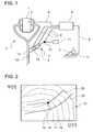
- FIG. 2is an illustration showing an example of an engine characteristic map
- FIG. 3is an illustration showing an example of a probability distribution of the engine characteristic map.
- FIG. 1there is seen an internal combustion engine 1 having an exhaust system 2 .
- a device 3 for determining the actual state of the internal combustion engine 1is provided. It is possible, in particular, for the rotational speed and/or the load state of the internal combustion engine 1 to be determined by the device 3 .
- a throttle or gas pedal 4which is fitted with a device 5 for determining the position of the throttle pedal 4 , is also provided.
- the device 5 for determining the position of the throttle pedal 4provides, in particular, an actuating variable for influencing the state of the internal combustion engine 1 , since the operating state of the internal combustion engine 1 , with regard in particular to rotational speed and/or load, varies according to the position of the throttle pedal 4 .
- a control device 6 and a device 7 for providing ammoniaare also provided.
- the control device 6is connected over data lines 8 to different components, in particular to the device 3 for determining the actual state of the internal combustion engine 1 , the device 5 for determining the position of the throttle pedal 4 , which is a so-called pedal transducer, and to parts of the device 7 for providing ammonia.
- the device 7 for providing ammoniais provided outside the exhaust gas, as shown in FIG. 1 . That is to say, the device 7 is constructed so as to normally not be traversed by exhaust gas. In the present exemplary embodiment, this is achieved in such a way that a solution of reducing agent or of a reducing agent precursor, which can cleave to ammonia or react to form ammonia, is evaporated in an evaporator 9 which is followed by a hydrolysis catalytic converter 10 in which a hydrolysis of the evaporated reducing agent precursor solution can take place.
- the hydrolysis catalytic converter 10includes a catalytically active layer or coating which is capable of catalyzing a reaction of urea to form ammonia.
- the evaporator 9can be connected to a reservoir 11 .
- a urea-water solutionis stored in the reservoir 11 .
- the urea-water solutioncan be fed into the evaporator 9 by a device 12 for supplying the urea-water solution, for example into the evaporator 9 by a pump.
- the hydrolysis catalytic converter 10 and the evaporator 9can be heated, with the control device 6 preferably also controlling the heating, in particular, of the evaporator 9 and if appropriate of the hydrolysis catalytic converter 10 as well.
- the components 9 , 10are preferably also connected over data lines 8 to the control device 6 .
- a gas mixture including ammoniaflows out of the hydrolysis catalytic converter 10 .
- the gas mixtureis introduced into the exhaust system 2 at an infeed point 13 .
- An SCR catalytic converter 14 for the selective catalytic reduction of nitrogen oxides in the exhaust gas of the internal combustion engine 1is provided downstream of the infeed point 13 .
- the hydrolysis catalytic converter 10 and the SCR catalytic converter 14may each include at least one honeycomb body which may preferably be constructed from metallic layers or include a ceramic monolith. In this case, a respectively correspondingly constructed catalytically active coating is applied to the honeycomb body, or catalytically active centers are correspondingly formed in the honeycomb body.
- the present actual state of the internal combustion engine 1is firstly recorded by the correspondingly constructed device, in particular with the rotational speed and/or the torque of the internal combustion engine 1 being determined.
- the present position of the throttle pedal 4is also determined through the use of the correspondingly constructed device 5 .
- the data produced in this wayis transmitted over the data lines 8 , which may either include a wire or have a wireless construction, to the control device 6 and are processed further therein.
- a possible nitrogen oxide emission of the internal combustion engine 1can now be calculated taking into consideration at least one previous value of the present actual state and/or the corresponding actuating variable such as the corresponding angle of the throttle pedal 4 .
- the present actual stateis compared with a previous actual state, and if appropriate a difference vector is determined which indicates a possible direction in the engine characteristic map.
- the change in the actuating variablethat is to say in particular in the position of the throttle pedal 4 , may also be taken into consideration. It is thus possible to infer, from a corresponding change in the position of the throttle pedal 4 , an acceleration or deceleration, which is now occurring, of a motor vehicle which is driven by the internal combustion engine 1 .
- FIG. 2graphically shows a so-called engine characteristic map 15 .
- the engine characteristic map 15shows the emitted quantity of nitrogen oxide as a function of rotational speed ⁇ and torque M. Both the rotational speed ⁇ and the torque M are specified in arbitrary units.
- the corresponding nitrogen oxide emissionsare plotted as a set of curves which connect values of equal nitrogen oxide emission to one another. For example, a first line 16 connects all the values of a nitrogen oxide emission of 100 ppm (parts per million), a second line 17 connects values with a nitrogen oxide emission of 200 ppm, a third line 18 connects values with a nitrogen oxide emission of 300 ppm, etc.
- a present actual state 19is defined by the associated rotational speed ⁇ and the associated torque M.
- FIG. 2also shows common acceleration profiles 20 .
- the common acceleration profiles 20indicate the reaction of the internal combustion engine 1 to an increase or reduction in rotational speed ⁇ , which is usually reflected in a change in the applied torque M.
- the profile of the acceleration profiles 20may vary as a function of external conditions such as in particular road surface, gradient, speed, air resistance, friction resistance and the like.
- a possible acceleration profile 20can be extrapolated from the change in the position of the throttle pedal 4 . In this case, it is possible in particular to revert to a parameter-adaptive adaptation method.
- FIG. 3shows an associated probability distribution. Proceeding from the actual state 19 of the internal combustion engine 1 , FIG. 3 shows the probability with which certain nominal states of the internal combustion engine 1 can be attained.
- a first line 21connects all those points which can be attained from the present actual state 19 with a probability of 90%.
- a second line 22connects points with a probability of 85% to one another, and a line 23 connects points with a probability of 80% to one another. It is possible, on the basis of the probability data, together with the change in the at least one actuating variable such as, for example, the position of the throttle pedal 4 , to very precisely calculate what nominal state can be attained as a result of the change in the actuating variable which has just taken place.
- the nitrogen oxide emission in the nominal stateis known on the basis of the engine characteristic map 15 , in such a way that the provision of a corresponding quantity of ammonia can then be initiated.
- the method according to the invention and the device according to the inventionextend the time margin for providing a corresponding quantity of ammonia as reducing agent for the selective catalytic reduction of the nitrogen oxides in the exhaust gas of an internal combustion engine 1 , in such a way that a time advantage is obtained.
- the time advantageis based, for example, on the extrapolation of the nitrogen oxide emission proceeding from the actual state 19 of the internal combustion engine 1 and the change in at least one actuating variable such as, for example, the change in the position of the throttle pedal 4 , taking into consideration the propagation time of the exhaust gas through the exhaust system 2 of the internal combustion engine 1 .
- inert systems for providing reducing agentto be used effectively in such a way that an improved conversion of the nitrogen oxides in the exhaust gas of the internal combustion engine 1 can be obtained.
Landscapes
- Chemical & Material Sciences (AREA)
- Engineering & Computer Science (AREA)
- Chemical Kinetics & Catalysis (AREA)
- Health & Medical Sciences (AREA)
- Environmental & Geological Engineering (AREA)
- Analytical Chemistry (AREA)
- Biomedical Technology (AREA)
- Combustion & Propulsion (AREA)
- General Chemical & Material Sciences (AREA)
- Oil, Petroleum & Natural Gas (AREA)
- Organic Chemistry (AREA)
- Inorganic Chemistry (AREA)
- Toxicology (AREA)
- Mechanical Engineering (AREA)
- General Engineering & Computer Science (AREA)
- Exhaust Gas After Treatment (AREA)
Abstract
Description
- a) recording at least one actuating variable for influencing a state of the internal combustion engine;
- b) calculating a possible nitrogen oxide emission of the internal combustion engine on a basis of an evaluation of at least one measured variable;
- c) calculating an ammonia quantity corresponding to a possible nitrogen oxide emission; and
- d) initiating a provision of the corresponding ammonia quantity by evaporation outside the exhaust gas in an evaporator and hydrolysis of a urea-water solution outside the exhaust gas, with a regulation of at least one of the following variables:
- i. a heating power of the evaporator, or
- ii. a quantity of the urea-water solution supplied to the evaporator, on a basis of the ammonia quantity calculated in step c).
Claims (5)
Applications Claiming Priority (4)
| Application Number | Priority Date | Filing Date | Title |
|---|---|---|---|
| DE102007031530 | 2007-05-08 | ||
| DE102007031530.0 | 2007-05-08 | ||
| DE102007031530ADE102007031530A1 (en) | 2007-05-08 | 2007-05-08 | Method for providing reducing agent for the selective catalytic reduction of nitrogen oxides and corresponding device |
| PCT/EP2008/055435WO2008135535A1 (en) | 2007-05-08 | 2008-05-02 | Method for providing ammonia for the selective catalytic reduction of nitrogen oxides, and corresponding device |
Related Parent Applications (1)
| Application Number | Title | Priority Date | Filing Date |
|---|---|---|---|
| PCT/EP2008/055435ContinuationWO2008135535A1 (en) | 2007-05-08 | 2008-05-02 | Method for providing ammonia for the selective catalytic reduction of nitrogen oxides, and corresponding device |
Publications (2)
| Publication Number | Publication Date |
|---|---|
| US20100037598A1 US20100037598A1 (en) | 2010-02-18 |
| US8341942B2true US8341942B2 (en) | 2013-01-01 |
Family
ID=39689431
Family Applications (1)
| Application Number | Title | Priority Date | Filing Date |
|---|---|---|---|
| US12/604,522Active2029-10-31US8341942B2 (en) | 2007-05-08 | 2009-10-23 | Method for providing ammonia for the selective catalytic reduction of nitrogen oxides and corresponding device |
Country Status (5)
| Country | Link |
|---|---|
| US (1) | US8341942B2 (en) |
| EP (1) | EP2145086B1 (en) |
| JP (1) | JP5199338B2 (en) |
| DE (1) | DE102007031530A1 (en) |
| WO (1) | WO2008135535A1 (en) |
Cited By (3)
| Publication number | Priority date | Publication date | Assignee | Title |
|---|---|---|---|---|
| US8790219B2 (en) | 2008-12-19 | 2014-07-29 | Ud Trucks Corporation | Exhaust emission purifying apparatus for engine |
| US9353665B2 (en) | 2014-09-15 | 2016-05-31 | Cummins Emission Solutions, Inc. | Ammonia generation system for an SCR system |
| US20190301332A1 (en)* | 2016-12-21 | 2019-10-03 | Perkins Engines Company Ltd | Method for Selective Catalytic Reduction System |
Families Citing this family (3)
| Publication number | Priority date | Publication date | Assignee | Title |
|---|---|---|---|---|
| EP3339588B1 (en)* | 2016-12-21 | 2021-03-03 | Perkins Engines Company Limited | An improved selective catalytic reduction system |
| JP2018189056A (en)* | 2017-05-10 | 2018-11-29 | トヨタ自動車株式会社 | Exhaust gas purification device for internal combustion engine |
| EP3415439B1 (en)* | 2017-06-13 | 2021-08-04 | HS Marston Aerospace Limited | Method and apparatus for fuel vaporising in catalytic fuel tank inerting |
Citations (15)
| Publication number | Priority date | Publication date | Assignee | Title |
|---|---|---|---|---|
| US5116579A (en) | 1989-02-02 | 1992-05-26 | Nippon Shokubai Kagaku Kogyo Co., Ltd. | Removing nitrogen oxides in exhaust gases from a diesel engine |
| DE19743302C1 (en) | 1997-09-30 | 1999-02-04 | Siemens Ag | Bubble jet pump injecting NOx reductant into diesel engine exhaust gases |
| US6032461A (en) | 1995-10-30 | 2000-03-07 | Toyota Jidosha Kabushiki Kaisha | Exhaust emission control apparatus for internal combustion engine |
| DE19843960A1 (en) | 1998-09-24 | 2000-03-30 | Siemens Ag | Method and device for the catalytic reduction of the pollutant content in the exhaust gas of an incineration plant |
| US6415602B1 (en) | 2000-10-16 | 2002-07-09 | Engelhard Corporation | Control system for mobile NOx SCR applications |
| DE10100420A1 (en) | 2001-01-08 | 2002-07-11 | Bosch Gmbh Robert | Method and device for controlling an exhaust gas aftertreatment system |
| US20030135323A1 (en)* | 2001-11-28 | 2003-07-17 | Omg Ag & Co. Kg | Method and device for operating a motor vehicle engine |
| US20040098972A1 (en) | 2002-11-21 | 2004-05-27 | Devesh Upadhyay | Diesel aftertreatment system |
| DE10346714A1 (en) | 2002-11-06 | 2004-06-17 | Ford Global Technologies, LLC, Dearborn | Diesel aftertreatment systems |
| DE20308348U1 (en) | 2003-02-18 | 2004-07-01 | Hjs Fahrzeugtechnik Gmbh & Co. | Assembly to break down ammonium carbonate to ammonium and surrender to an automotive diesel exhaust catalytic converter |
| EP1481719A2 (en) | 2003-05-28 | 2004-12-01 | Hitachi, Ltd. | Engine exhaust gas treatment system and exhaust gas treatment process |
| DE102004030782A1 (en) | 2004-06-25 | 2006-01-19 | Fev Motorentechnik Gmbh | Vehicle control unit with a neural network |
| US20060101811A1 (en) | 2004-10-29 | 2006-05-18 | Jan-Roger Linna | Reducing agent metering system for reducing NOx in lean burn internal combustion engines |
| WO2006087541A1 (en) | 2005-02-16 | 2006-08-24 | Imi Vision Limited | Exhaust gas treatment |
| US20090120079A1 (en) | 2005-02-16 | 2009-05-14 | Imi Vision Limited | Exhaust gas treatment |
Family Cites Families (6)
| Publication number | Priority date | Publication date | Assignee | Title |
|---|---|---|---|---|
| JPH0757303B2 (en)* | 1991-05-23 | 1995-06-21 | 株式会社新潟鉄工所 | Denitration control device and method |
| JPH06335A (en)* | 1992-06-16 | 1994-01-11 | Mitsubishi Heavy Ind Ltd | Controller for injected quantity of ammonia |
| JP3410823B2 (en)* | 1994-07-14 | 2003-05-26 | 東京電力株式会社 | DeNOx control device |
| JP3869314B2 (en)* | 2002-03-29 | 2007-01-17 | バブコック日立株式会社 | Exhaust gas denitration apparatus and urea vaporizer used therefor |
| US20040083722A1 (en)* | 2002-11-06 | 2004-05-06 | Ford Global Technologies, Inc. | Diesel aftertreatment systems |
| JP3823923B2 (en)* | 2003-01-16 | 2006-09-20 | 日産自動車株式会社 | Exhaust purification device |
- 2007
- 2007-05-08DEDE102007031530Apatent/DE102007031530A1/ennot_activeWithdrawn
- 2008
- 2008-05-02EPEP08750004.7Apatent/EP2145086B1/enactiveActive
- 2008-05-02JPJP2010506906Apatent/JP5199338B2/enactiveActive
- 2008-05-02WOPCT/EP2008/055435patent/WO2008135535A1/enactiveApplication Filing
- 2009
- 2009-10-23USUS12/604,522patent/US8341942B2/enactiveActive
Patent Citations (24)
| Publication number | Priority date | Publication date | Assignee | Title |
|---|---|---|---|---|
| DE69005322T2 (en) | 1989-02-02 | 1994-05-19 | Nippon Catalytic Chem Ind | Process for reducing nitrogen oxides from diesel engine exhaust. |
| DE69005322T3 (en) | 1989-02-02 | 1999-01-07 | Nippon Shokubai Kagaku Kogyo Co., Ltd., Osaka | Process for reducing nitrogen oxides from diesel engine exhaust. |
| US5116579A (en) | 1989-02-02 | 1992-05-26 | Nippon Shokubai Kagaku Kogyo Co., Ltd. | Removing nitrogen oxides in exhaust gases from a diesel engine |
| DE69625823T2 (en) | 1995-10-30 | 2003-09-04 | Toyota Jidosha K.K., Toyota | EXHAUST CONTROL DEVICE FOR INTERNAL COMBUSTION ENGINE |
| US6032461A (en) | 1995-10-30 | 2000-03-07 | Toyota Jidosha Kabushiki Kaisha | Exhaust emission control apparatus for internal combustion engine |
| DE19743302C1 (en) | 1997-09-30 | 1999-02-04 | Siemens Ag | Bubble jet pump injecting NOx reductant into diesel engine exhaust gases |
| DE19843960A1 (en) | 1998-09-24 | 2000-03-30 | Siemens Ag | Method and device for the catalytic reduction of the pollutant content in the exhaust gas of an incineration plant |
| US6415602B1 (en) | 2000-10-16 | 2002-07-09 | Engelhard Corporation | Control system for mobile NOx SCR applications |
| DE60113147T2 (en) | 2000-10-16 | 2006-06-14 | Engelhard Corp | CONTROL SYSTEM FOR SCR APPLICATIONS |
| US7028465B2 (en) | 2001-01-08 | 2006-04-18 | Robert Bosch Gmbh | Method and device for controlling an exhaust treatment system |
| DE10100420A1 (en) | 2001-01-08 | 2002-07-11 | Bosch Gmbh Robert | Method and device for controlling an exhaust gas aftertreatment system |
| US20030135323A1 (en)* | 2001-11-28 | 2003-07-17 | Omg Ag & Co. Kg | Method and device for operating a motor vehicle engine |
| US20050066652A1 (en) | 2002-11-06 | 2005-03-31 | Ketcher David Arthur | Diesel aftertreatment systems |
| DE10346714A1 (en) | 2002-11-06 | 2004-06-17 | Ford Global Technologies, LLC, Dearborn | Diesel aftertreatment systems |
| DE10346715A1 (en) | 2002-11-21 | 2004-06-17 | Ford Global Technologies, LLC, Dearborn | Diesel exhaust aftertreatment systems |
| US20040098972A1 (en) | 2002-11-21 | 2004-05-27 | Devesh Upadhyay | Diesel aftertreatment system |
| DE20308348U1 (en) | 2003-02-18 | 2004-07-01 | Hjs Fahrzeugtechnik Gmbh & Co. | Assembly to break down ammonium carbonate to ammonium and surrender to an automotive diesel exhaust catalytic converter |
| US20050013756A1 (en) | 2003-05-28 | 2005-01-20 | Kiyoshi Amou | Engine exhaust gas treatment system and exhaust gas treatment process |
| EP1481719A2 (en) | 2003-05-28 | 2004-12-01 | Hitachi, Ltd. | Engine exhaust gas treatment system and exhaust gas treatment process |
| DE102004030782A1 (en) | 2004-06-25 | 2006-01-19 | Fev Motorentechnik Gmbh | Vehicle control unit with a neural network |
| US20070203616A1 (en) | 2004-06-25 | 2007-08-30 | Eric Borrmann | Motor vehicle control device provided with a neuronal network |
| US20060101811A1 (en) | 2004-10-29 | 2006-05-18 | Jan-Roger Linna | Reducing agent metering system for reducing NOx in lean burn internal combustion engines |
| WO2006087541A1 (en) | 2005-02-16 | 2006-08-24 | Imi Vision Limited | Exhaust gas treatment |
| US20090120079A1 (en) | 2005-02-16 | 2009-05-14 | Imi Vision Limited | Exhaust gas treatment |
Non-Patent Citations (1)
| Title |
|---|
| International Search Report dated Sep. 1, 2008. |
Cited By (4)
| Publication number | Priority date | Publication date | Assignee | Title |
|---|---|---|---|---|
| US8790219B2 (en) | 2008-12-19 | 2014-07-29 | Ud Trucks Corporation | Exhaust emission purifying apparatus for engine |
| US9353665B2 (en) | 2014-09-15 | 2016-05-31 | Cummins Emission Solutions, Inc. | Ammonia generation system for an SCR system |
| US20190301332A1 (en)* | 2016-12-21 | 2019-10-03 | Perkins Engines Company Ltd | Method for Selective Catalytic Reduction System |
| US10934917B2 (en)* | 2016-12-21 | 2021-03-02 | Perkins Engines Company Limited | Method for selective catalytic reduction system |
Also Published As
| Publication number | Publication date |
|---|---|
| WO2008135535A1 (en) | 2008-11-13 |
| EP2145086B1 (en) | 2013-07-10 |
| JP2010526250A (en) | 2010-07-29 |
| DE102007031530A1 (en) | 2008-11-13 |
| JP5199338B2 (en) | 2013-05-15 |
| EP2145086A1 (en) | 2010-01-20 |
| US20100037598A1 (en) | 2010-02-18 |
Similar Documents
| Publication | Publication Date | Title |
|---|---|---|
| US8551430B2 (en) | Method for the selective catalytic reduction of nitrogen oxides in exhaust gas from an internal combustion engine, and exhaust system | |
| JP5653618B2 (en) | Control of selective catalytic reduction | |
| US8341942B2 (en) | Method for providing ammonia for the selective catalytic reduction of nitrogen oxides and corresponding device | |
| US7603846B2 (en) | Method for operating an internal combustion engine and a device for carrying out the method | |
| EP2126306B1 (en) | On-board-diagnosis method for an exhaust aftertreatment system and on-board-diagnosis system for an exhaust aftertreatment system | |
| US7546728B2 (en) | Method for operating a catalytic converter used for purifying the exhaust gas of an internal combustion engine and a device for implementing the method | |
| CN111226026B (en) | Method for operating an internal combustion engine of a motor vehicle, in particular a motor vehicle | |
| US20100122523A1 (en) | Cold-start engine loading for accelerated warming of exhaust aftertreatment system | |
| CN115405432B (en) | Method for operating an internal combustion engine | |
| CN101660456B (en) | Lean nitrogen oxide emission control system and method | |
| US20190345861A1 (en) | Method and system for controlling an ammonia coverage degree profile | |
| US8551433B2 (en) | SCR catalyst system and method for the operation thereof | |
| JP2018528350A (en) | Exhaust treatment system and method for treatment of exhaust gas streams | |
| US20080216467A1 (en) | Method and Device for Reducing the Nitrogen Oxide Proportion in the Exhaust Gas of an Internal Combustion Engine | |
| CN109931129B (en) | Method and device for monitoring an exhaust gas aftertreatment system of an internal combustion engine | |
| KR102097094B1 (en) | Method for exhaust gas stream treatment and exhaust treatment system | |
| CN107975407B (en) | Method for regulating an exhaust gas aftertreatment device of an internal combustion engine | |
| US9429061B2 (en) | Method for metering a reducing agent into an exhaust-gas treatment device, exhaust-gas treatment device and motor vehicle | |
| US20200109651A1 (en) | System and methods of integrated control of combustion and scr systems | |
| US9500111B2 (en) | Method for determining reducing agent slippage and motor vehicle employing the method | |
| WO2014189454A1 (en) | Method for distributing and storing urea upstream a catalytic device in an exhaust treatment system | |
| US20230028415A1 (en) | Method, computing unit and computer program for operating an scr catalytic converter | |
| CN113544365B (en) | Method for adjusting the loading of a particle filter | |
| US20200040786A1 (en) | Process for optimizing a removal of nitrogen oxides from the gases in an engine exhaust line according to a selective catalytic reduction | |
| EP3485152B1 (en) | Method and system for use when correcting supply of an additive to an exhaust gas stream |
Legal Events
| Date | Code | Title | Description |
|---|---|---|---|
| AS | Assignment | Owner name:EMITEC GESELLSCHAFT FUER EMISSIONSTECHNOLOGIE MBH, Free format text:ASSIGNMENT OF ASSIGNORS INTEREST;ASSIGNORS:BRUECK, ROLF;HIRTH, PETER;REEL/FRAME:028699/0711 Effective date:20090929 | |
| STCF | Information on status: patent grant | Free format text:PATENTED CASE | |
| FEPP | Fee payment procedure | Free format text:PAYOR NUMBER ASSIGNED (ORIGINAL EVENT CODE: ASPN); ENTITY STATUS OF PATENT OWNER: LARGE ENTITY | |
| FPAY | Fee payment | Year of fee payment:4 | |
| MAFP | Maintenance fee payment | Free format text:PAYMENT OF MAINTENANCE FEE, 8TH YEAR, LARGE ENTITY (ORIGINAL EVENT CODE: M1552); ENTITY STATUS OF PATENT OWNER: LARGE ENTITY Year of fee payment:8 | |
| AS | Assignment | Owner name:CONTINENTAL EMITEC GMBH, GERMANY Free format text:CHANGE OF NAME;ASSIGNOR:EMITEC GESELLSCHAFT FUER EMISSIONSTECHNOLGIE MBH;REEL/FRAME:067125/0944 Effective date:20141024 | |
| AS | Assignment | Owner name:CONTINENTAL AUTOMOTIVE GMBH, GERMANY Free format text:ASSIGNMENT OF ASSIGNORS INTEREST;ASSIGNOR:CONTINENTAL EMITEC GMBH;REEL/FRAME:070818/0195 Effective date:20230825 | |
| AS | Assignment | Owner name:VITESCO TECHNOLOGIES GMBH, GERMANY Free format text:ASSIGNMENT OF ASSIGNORS INTEREST;ASSIGNOR:CONTINENTAL AUTOMOTIVE GMBH;REEL/FRAME:071028/0838 Effective date:20230825 |