US8340743B2 - Methods, systems and computer program products for positioning a guidance apparatus relative to a patient - Google Patents
Methods, systems and computer program products for positioning a guidance apparatus relative to a patientDownload PDFInfo
- Publication number
- US8340743B2 US8340743B2US12/273,827US27382708AUS8340743B2US 8340743 B2US8340743 B2US 8340743B2US 27382708 AUS27382708 AUS 27382708AUS 8340743 B2US8340743 B2US 8340743B2
- Authority
- US
- United States
- Prior art keywords
- point
- guide device
- plane
- ptl
- guide
- Prior art date
- Legal status (The legal status is an assumption and is not a legal conclusion. Google has not performed a legal analysis and makes no representation as to the accuracy of the status listed.)
- Active, expires
Links
Images


Classifications
- A—HUMAN NECESSITIES
- A61—MEDICAL OR VETERINARY SCIENCE; HYGIENE
- A61B—DIAGNOSIS; SURGERY; IDENTIFICATION
- A61B90/00—Instruments, implements or accessories specially adapted for surgery or diagnosis and not covered by any of the groups A61B1/00 - A61B50/00, e.g. for luxation treatment or for protecting wound edges
- A61B90/10—Instruments, implements or accessories specially adapted for surgery or diagnosis and not covered by any of the groups A61B1/00 - A61B50/00, e.g. for luxation treatment or for protecting wound edges for stereotaxic surgery, e.g. frame-based stereotaxis
- A61B90/11—Instruments, implements or accessories specially adapted for surgery or diagnosis and not covered by any of the groups A61B1/00 - A61B50/00, e.g. for luxation treatment or for protecting wound edges for stereotaxic surgery, e.g. frame-based stereotaxis with guides for needles or instruments, e.g. arcuate slides or ball joints
- A—HUMAN NECESSITIES
- A61—MEDICAL OR VETERINARY SCIENCE; HYGIENE
- A61B—DIAGNOSIS; SURGERY; IDENTIFICATION
- A61B34/00—Computer-aided surgery; Manipulators or robots specially adapted for use in surgery
- A61B34/10—Computer-aided planning, simulation or modelling of surgical operations
- A61B2034/107—Visualisation of planned trajectories or target regions
Definitions
- the present inventionrelates generally to medical systems and methods and, more particularly, to medical systems and methods for intrabody procedures.
- DBSDeep Brain Stimulation
- Other electro-stimulation therapieshave also been carried out or proposed using internal stimulation of the sympathetic nerve chain and/or spinal cord, etc.
- the Activa® systemincludes an implantable pulse generator stimulator that is positioned in the chest cavity of the patient and a lead with axially spaced apart electrodes that is implanted with the electrodes disposed in neural tissue.
- the leadis tunneled subsurface from the brain to the chest cavity connecting the electrodes with the pulse generator.
- These leadscan have multiple exposed electrodes at the distal end that are connected to conductors which run along the length of the lead and connect to the pulse generator placed in the chest cavity.
- DBSdigital signal-to-senor
- the DBS probesare placed in neural tissue with the electrodes transmitting a signal to the thalamus region of the brain.
- DBS stimulation leadsare conventionally implanted during a stereotactic surgery, based on pre-operative MRI and CT images. These procedures can be long in duration and may have reduced efficacy as it has been reported that, in about 30% of the patients implanted with these devices, the clinical efficacy of the device/procedure is less than optimum. Notwithstanding the above, there remains a need for alternative MRI-guided interventional tools for DBS, as well as for other interventional medical procedures.
- Some embodiments of the present inventionare directed to methods for positioning a guide device for placement of an interventional object in a body, the guide device having a guide axis.
- the methodsinclude: determining a target point in the body and a reference point, wherein the target point and the reference point define a planned trajectory line (PTL) extending through each; determining a visualization plane, wherein the PTL intersects the visualization plane at a sighting point; mounting the guide device relative to the body to move with respect to the PTL, wherein the guide device does not intersect the visualization plane; determining a point of intersection (GPP) between the guide axis and the visualization plane; and aligning the GPP with the sighting point in the visualization plane.
- PTLplanned trajectory line
- Some embodiments of the present inventionare directed to methods for positioning a guide device for placement of an interventional object in a body, the guide device having a guide axis.
- the methodsinclude: determining a target point in the body and a pivot point, wherein the target point and the pivot point define a planned trajectory line (PTL) extending through each; determining a visualization plane, wherein the PTL intersects the visualization plane at a sighting point, and wherein the sighting point is located on a segment of the PTL on a side of the pivot point proximate the target point; mounting the guide device relative to the body to pivot about the pivot point with respect to the PTL; determining a point of intersection (GPP) between the guide axis and the visualization plane; and aligning the GPP with the sighting point in the visualization plane.
- PTLplanned trajectory line
- Some embodiments of the present inventionare directed to methods for positioning a guide device for placement of an interventional object in a body, the guide device having a guide axis.
- the methodsinclude: determining a target point in the body and a reference point, wherein the target point and the reference point define a planned trajectory line (PTL) extending through each; determining a visualization plane, wherein the PTL intersects the visualization plane at a sighting point, and wherein the sighting point is located within the body; mounting the guide device relative to the body to move with respect to the PTL; determining a point of intersection (GPP) between the guide axis and the visualization plane; and aligning the GPP with the sighting point in the visualization plane.
- PTLplanned trajectory line
- Some embodiments of the present inventionare directed to methods for positioning a guide device for placement of an interventional object in a body, the guide device having a guide axis.
- the methodsinclude: determining a target point in the body and a reference point, wherein the target point and the reference point define a plained trajectory line (PTL) extending through each; determining a visualization plane, wherein the PTL intersects the visualization plane at a sighting point, and wherein the PTL is orthogonal to the visualization plane; mounting the guide device relative to the body to move with respect to the PTL; determining a point of intersection (GPP) between the guide axis and the visualization plane; and aligning the GPP with the sighting point in the visualization plane.
- PTLplained trajectory line
- Some embodiments of the present inventionare directed to methods for positioning a guide device for placement of an interventional object in a body, the guide device having a guide axis.
- the methodsinclude: determining a target point in the body and a reference point, wherein the target point and the reference point define a planned trajectory line (PTL) extending through each; determining a visualization plane, wherein the PTL intersects the visualization plane at a sighting point; mounting the guide device relative to the body to translate with respect to the PTL; determining a point of intersection (GPP) between the guide axis and the visualization plane; and aligning the GPP with the sighting point in the visualization plane.
- PTLplanned trajectory line
- a system for positioning a guide device for placement of an interventional object in a bodyincludes a guide device having a guide axis and a controller.
- the controlleris configured to determine a target point in the body and a reference point, wherein the target point and the reference point define a planned trajectory line (PTL) extending through each; determine a visualization plane, wherein the PTL intersects the visualization plane at a sighting point; and determine a point of intersection (GPP) between the guide axis and the visualization plane.
- the guide deviceis mountable relative to the body to move with respect to the PTL, and such that the guide device does not intersect the visualization plane.
- the guide devicecan be adjusted with respect to the body to align the GPP with the sighting point in the visualization plane.
- a system for positioning a guide device for placement of an interventional object in a bodyincludes a guide device having a guide axis and a controller.
- the controlleris configured to determine a target point in the body and a pivot point, wherein the target point and the pivot point define a planned trajectory line (PTL) extending through each; determine a visualization plane, wherein the PTL intersects the visualization plane at a sighting point and the sighting point is located on a side of the pivot point proximate the target point; and determine a point of intersection (GPP) between the guide axis and the visualization plane.
- the guide deviceis mountable relative to the body to pivot about the pivot point with respect to the PTL. The guide device can be adjusted with respect to the body to align the GPP with the sighting point in the visualization plane.
- a system for positioning a guide device for placement of an interventional object in a bodyincludes a guide device having a guide axis and a controller.
- the controlleris configured to determine a target point in the body and a reference point, wherein the target point and the reference point define a planned trajectory line (PTL) extending through each; determine a visualization plane, wherein the PTL intersects the visualization plane at a sighting point and the sighting point is located within the body; and determine a point of intersection (GPP) between the guide axis and the visualization plane.
- the guide deviceis mountable relative to the body to move with respect to the PTL.
- the guide devicecan be adjusted with respect to the body to align the GPP with the sighting point in the visualization plane.
- a system for positioning a guide device for placement of an interventional object in a bodyincludes a guide device having a guide axis and a controller.
- the controlleris configured to determine a target point in the body and a reference point, wherein the target point and the reference point define a planned trajectory line (PTL) extending through each; determine a visualization plane, wherein the PTL intersects the visualization plane at a sighting point and the PTL is orthogonal to the visualization plane; and determine a point of intersection (GPP) between the guide axis and the visualization plane.
- the guide deviceis mountable relative to the body to move with respect to the PTL.
- the guide devicecan be adjusted with respect to the body to align the GPP with the sighting point in the visualization plane.
- a system for positioning a guide device for placement of an interventional object in a bodyincludes a guide device having a guide axis and a controller.
- the controlleris configured to determine a target point in the body and a reference point, wherein the target point and the reference point define a planned trajectory line (PTL) extending through each; determine a visualization plane, wherein the PTL intersects the visualization plane at a sighting point; and determine a point of intersection (GPP) between the guide axis and the visualization plane.
- the guide deviceis mountable relative to the body to translate with respect to the PTL.
- the guide devicecan be adjusted with respect to the body to align the GPP with the sighting point in the visualization plane.
- a computer program product for positioning a guide device for placement of an interventional object in a body, the guide device having a guide axisincludes a computer readable medium having computer readable program code embodied therein.
- the computer usable program codeincludes: computer readable program code configured to determine a target point in the body and a reference point, wherein the target point and the reference point define a planned trajectory line (PTL) extending through each; computer readable program code configured to determine a visualization plane, wherein the PTL intersects the visualization plane at a sighting point; and computer readable program code configured to determine a point of intersection (GPP) between the guide axis and the visualization plane when the guide device does not intersect the visualization plane.
- PTLplanned trajectory line
- a computer program product for positioning a guide device for placement of an interventional object in a bodyincludes a computer readable medium having computer readable program code embodied therein.
- the computer usable program codeincludes: computer readable program code configured to determine a target point in the body and a pivot point, wherein the target point and the pivot point define a planned trajectory line (PTL) extending through each, and wherein the sighting point is located on a segment of the PTL on a side of the pivot point proximate the target point; computer readable program code configured to determine a visualization plane, wherein the PTL intersects the visualization plane at a sighting point; and computer readable program code configured to determine a point of intersection (GPP) between the guide axis.
- PTLplanned trajectory line
- a computer program product for positioning a guide device for placement of an interventional object in a bodyincludes a computer readable medium having computer readable program code embodied therein.
- the computer usable program codeincludes: computer readable program code configured to determine a target point in the body and a reference point, wherein the target point and the reference point define a planned trajectory line (PTL) extending through each; computer readable program code configured to determine a visualization plane, wherein the PTL intersects the visualization plane at a sighting point and the sighting point is located within the body; and computer readable program code configured to determine a point of intersection (GPP) between the guide axis.
- PTLplanned trajectory line
- a computer program product for positioning a guide device for placement of an interventional object in a body, the guide device having a guide axisincludes a computer readable medium having computer readable program code embodied therein.
- the computer usable program codeincludes: computer readable program code configured to determine a target point in the body and a reference point, wherein the target point and the reference point define a planned trajectory line (PTL) extending through each; computer readable program code configured to determine a visualization plane, wherein the PTL intersects the visualization plane at a sighting point, and wherein the PTL is orthogonal to the visualization plane; and computer readable program code configured to determine a point of intersection (GPP) between the guide axis.
- PTLplanned trajectory line
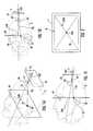
- FIGS. 1A , 1 B, and 1 Care schematic perspective, top and side views of a portion of patient body and logical elements associated with methods and systems according to embodiments of the present invention wherein a guide device thereof is oriented in a first, non-aligned position.
- FIG. 2is a schematic view of an exemplary image displayed to an operator when the guide device is in the first position.
- FIGS. 3A , 3 B and 3 Care schematic perspective, top and side views of the patient body and logical elements of FIGS. 1A-1C but showing the guide device is oriented in a second, aligned position.
- FIG. 4is a schematic view of an image displayed to an operator when the guide device is in the second position.
- FIG. 5is a schematic diagram of a system according to embodiments of the present invention.
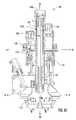
- FIG. 6Ais a front perspective view of a trajectory guide apparatus that may form a part of the system of FIG. 5 .
- FIG. 6Bis a rear perspective view of the trajectory guide apparatus of FIG. 6A .
- FIG. 6Cis a cross-sectional view of the trajectory guide apparatus of FIG. 6A taken along the line 6 C- 6 C of FIG. 6A .
- FIG. 7is a data processing system according to embodiments of the present invention.
- FIGS. 8A , 8 B and 8 Care schematic perspective, top and side views of a portion of a patient body and logical elements associated with methods and systems according to further embodiments of the present invention wherein a guide device thereof is oriented in a first, non-aligned position.
- FIGS. 9A , 9 B and 9 Care schematic perspective, top and side views of the portion of the patient body and logical elements of FIGS. 8A-8C but showing the guide device is oriented in a second, aligned position.
- FIG. 10is a schematic side view of a portion of a patient body and logical elements associated with methods and systems according to further embodiments of the present invention wherein a guide device thereof is oriented in a first, non-aligned position.
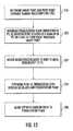
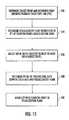
- FIGS. 11-15are flow charts illustrating methods and/or operations according to embodiments of the present invention.
- spatially relative termssuch as “under”, “below”, “lower”, “over”, “upper” and the like, may be used herein for ease of description to describe one element or feature's relationship to another element(s) or feature(s) as illustrated in the figures. It will be understood that the spatially relative terms are intended to encompass different orientations of the device in use or operation in addition to the orientation depicted in the figures. For example, if the device in the figures is inverted, elements described as “under” or “beneath” other elements or features would then be oriented “over” the other elements or features. Thus, the exemplary term “under” can encompass both an orientation of “over” and “under”.
- the devicemay be otherwise oriented (rotated 90 degrees or at other orientations) and the spatially relative descriptors used herein interpreted accordingly.
- the terms “upwardly”, “downwardly”, “vertical”, “horizontal” and the likeare used herein for the purpose of explanation only unless specifically indicated otherwise.
- Exemplary embodimentsare described below with reference to block diagrams and/or flowchart illustrations of methods, apparatus (systems and/or devices) and/or computer program products. It is understood that a block of the block diagrams and/or flowchart illustrations, and combinations of blocks in the block diagrams and/or flowchart illustrations, can be implemented by computer program instructions. These computer program instructions may be provided to a processor of a general purpose computer, special purpose computer, and/or other programmable data processing apparatus to produce a machine, such that the instructions, which execute via the processor of the computer and/or other programmable data processing apparatus, create means (functionality) and/or structure for implementing the functions/acts specified in the block diagrams and/or flowchart block or blocks.
- These computer program instructionsmay also be stored in a computer-readable memory that can direct a computer or other programmable data processing apparatus to function in a particular maimer, such that the instructions stored in the computer-readable memory produce an article of manufacture including instructions which implement the functions/acts specified in the block diagrams and/or flowchart block or blocks.
- the computer program instructionsmay also be loaded onto a computer or other programmable data processing apparatus to cause a series of operational steps to be performed on the computer or other programmable apparatus to produce a computer-implemented process such that the instructions which execute on the computer or other programmable apparatus provide steps for implementing the functions/acts specified in the block diagrams and/or flowchart block or blocks.
- exemplary embodimentsmay be implemented in hardware and/or in software (including firmware, resident software, micro-code, etc.). Furthermore, exemplary embodiments may take the form of a computer program product on a computer-usable or computer-readable storage medium having computer-usable or computer-readable program code embodied in the medium for use by or in connection with an instruction execution system.
- a computer-usable or computer-readable mediummay be any medium that can contain, store, communicate, propagate, or transport the program for use by or in connection with the instruction execution system, apparatus, or device.
- the computer-usable or computer-readable mediummay be, for example but not limited to, an electronic, magnetic, optical, electromagnetic, infrared, or semiconductor system, apparatus, device, or propagation medium. More specific examples (a non-exhaustive list) of the computer-readable medium would include the following: an electrical connection having one or more wires, a portable computer diskette, a random access memory (RAM), a read-only memory (ROM), an erasable programmable read-only memory (EPROM or Flash memory), an optical fiber, and a portable compact disc read-only memory (CD-ROM).
- RAMrandom access memory
- ROMread-only memory
- EPROM or Flash memoryerasable programmable read-only memory
- CD-ROMportable compact disc read-only memory
- the computer-usable or computer-readable mediumcould even be paper or another suitable medium upon which the program is printed, as the program can be electronically captured, via, for instance, optical scanning of the paper or other medium, then compiled, interpreted, or otherwise processed in a suitable manner, if necessary, and then stored in a computer memory.
- Computer program code for carrying out operations of data processing systems discussed hereinmay be written in a high-level programming language, such as Java, AJAX (Asynchronous JavaScript), C, and/or C++, for development convenience.
- computer program code for carrying out operations of exemplary embodimentsmay also be written in other programming languages, such as, but not limited to, interpreted languages.
- Some modules or routinesmay be written in assembly language or even micro-code to enhance performance and/or memory usage.
- embodimentsare not limited to a particular programming language. It will be further appreciated that the functionality of any or all of the program modules may also be implemented using discrete hardware components, one or more application specific integrated circuits (ASICs), or a programmed digital signal processor or microcontroller.
- ASICsapplication specific integrated circuits
- each block in the flow charts or block diagramsrepresents a module, segment, or portion of code, which comprises one or more executable instructions for implementing the specified logical function(s).
- the functions noted in the blocksmay occur out of the order noted in the figures. For example, two blocks shown in succession may in fact be executed substantially concurrently.
- MRI-visiblemeans that a device or feature thereof is visible, directly or indirectly, in an MRI image.
- the visibilitymay be indicated by the increased SNR of the MRI signal proximate to the device (the device can act as an MRI receive antenna to collect signal from local tissue) and/or that the device actually generates MRI signal itself, such as via suitable hydro-based coatings and/or fluid (typically aqueous solutions) filled cavities.
- MRI-compatiblemeans that a device is safe for use in an MRI environment and/or can operate as intended in an MRI environment, and, as such, if residing within the high-field strength region of the magnetic field, is typically made of a non-ferromagnetic MRI-compatible material(s) suitable to reside and/or operate in a high magnetic field environment.
- facial markerrefers to a marker that can be identified visually and/or using electronic image recognition, electronic interrogation of MRI image data, or three-dimensional electrical signals to define a position or orientation and/or find a feature or component in 3-D space.
- methods, systems and computer program productsare provided for positioning a guidance apparatus relative to a patient.
- the methods, systems and computer program productsform a part of or operate with MRI-compatible interventional systems.
- the systemsinclude trajectory guide systems and/or apparatus and related components and methods.
- the trajectory guide apparatus and methodsare frameless stereotactic trajectory guide apparatus that may be particularly suitable for deep brain interventional procedures, but may be used in other target anatomical locations as well.
- the guide apparatusis used to place implantable DBS leads for brain stimulation, typically deep brain stimulation.
- Some embodiments of the inventionare directed to MRI interventional procedures and provide interventional tools and/or therapies that may be used to locally place surgical interventional objects, tools or therapies in vivo to site specific regions using an MRI system.
- the interventional toolscan be used to define an MRI-guided trajectory or access path to an in vivo treatment site.
- an MRIcan be used to visualize (and/or locate) a therapeutic region of interest inside the brain and utilize an MRI to visualize (and/or locate) an interventional tool or tools that will be used to deliver therapy and/or to place a chronically implanted device that will deliver one or more therapies. Then, using the imaging data produced by the MRI system regarding the location of the therapeutic region of interest and the location of the interventional tool, the system and/or physician can make positional adjustments to the interventional tool so as to align the trajectory of the interventional tool, so that when inserted into the body, the trajectory of the interventional tool will intersect with the therapeutic region of interest.
- an interventional probecan be advanced, such as through an open lumen inside of the interventional tool, so that the interventional probe follows the trajectory of the interventional tool and proceeds to the therapeutic region of interest.
- the interventional tool and the interventional probemay or may not be part of the same component or structure.
- a method for positioning a guide device for placement of an interventional object in a bodyincludes determining a target point in the body and a reference point (Block 202 ).
- the target point and the reference pointdefine a planned trajectory line (PTL) that extends through each.
- a visualization planeis determined (Block 206 ).
- the PTLintersects the visualization plane at a sighting point.
- the guide deviceis mounted relative to the body to move with respect to the PTL (Block 208 ).
- the guide devicedoes not intersect the visualization plane.
- a point of intersection (GPP) between the guide axis and the visualization planeis determined (Block 210 ).
- the GPPis aligned with the sighting point in the visualization plane (Block 212 ).
- a method for positioning a guide device for placement of an interventional object in a bodyincludes determining a target point in the body and a pivot point (Block 216 ).
- the pivot point and the reference pointdefine a planned trajectory line (PTL) that extends through each.
- a visualization planeis determined (Block 220 ).
- the PTLintersects the visualization plane at a sighting point and the sighting point is located on a segment of the PTL on a side of the pivot point proximate the target point.
- the guide deviceis mounted relative to the body to be able to move with respect to the PTL (Block 222 ).
- a point of intersection (GPP) between the guide axis and the visualization planeis determined (Block 224 ).
- the GPPis aligned with the sighting point in the visualization plane (Block 226 ).
- a method for positioning a guide device for placement of an interventional object in a bodyincludes determining a target point in the body and a reference point (Block 230 ).
- the target point and the reference pointdefine a planned trajectory line (PTL) extending through each.
- a visualization planeis determined (Block 234 ).
- the PTLintersects the visualization plane at a sighting point and the sighting point is located within the body.
- the guide deviceis mounted relative to the body to move with respect to the PTL (Block 236 ).
- a point of intersection (GPP) between the guide axis and the visualization planeis determined (Block 238 ).
- the GPPis aligned with the sighting point in the visualization plane (Block 240 ).
- a method for positioning a guide device for placement of an interventional object in a bodyincludes determining a target point in the body and a reference point (Block 242 ).
- the target point and the reference pointdefine a planned trajectory line (PTL) extending through each.
- a visualization planeis determined (Block 246 ).
- the PTLintersects the visualization plane at a sighting point and the PTL is orthogonal to the visualization plane.
- the guide deviceis mounted relative to the body to move with respect to the PTL (Block 248 ).
- a point of intersection (GPP) between the guide axis and the visualization planeis determined (Block 250 ).
- the GPPis aligned with the sighting point in the visualization plane (Block 252 ).
- a method for positioning a guide device for placement of an interventional object in a bodyincludes determining a target point in the body and a reference point (Block 254 ).
- the target point and the reference pointdefine a planned trajectory line (PTL) extending through each.
- a visualization planeis determined (Block 258 ).
- the PTLintersects the visualization plane at a sighting point.
- the guide deviceis mounted relative to the body to translate with respect to the PTL (Block 260 ).
- a point of intersection (GPP) between the guide axis and the visualization planeis determined (Block 262 ).
- the GPPis aligned with the sighting point in the visualization plane (Block 264 ).
- FIGS. 1A-4Systems and methods according to embodiments of the present invention will be described with reference to FIGS. 1A-4 . These exemplary operations are described with respect to deep brain interventional procedures. While embodiments of the present invention are particularly suitable for same, embodiments of the present invention are not limited to use with deep brain procedures, however, and may be suitable for other surgical uses including robotic or other types of intrabody surgeries for other locations.
- FIGS. 1A-CA body B of a patient (as shown, a patient's head) is shown schematically in FIGS. 1A-C .
- FIG. 1Ais a perspective view
- FIG. 1Bis a top view
- FIG. 1Cis a side view.
- the body B of the patientis scanned using an MRI scanner.
- the MRI scannerscans the body B and generates corresponding MR image data. From the MR image data, MR images are obtained of the patient's body.
- the scansinclude scans of the patient's head and the MR images obtained visualize the patient's skull and brain.
- a target region TR(which may also be referred to as a target therapeutic site or region of interest) in the body B is identified.
- the target region TRmay be identified by MRI scanning the body B and with reference to known physiological landmarks.
- physiological landmarkssuch as the AC, PC and MCP points (brain atlases can give the location of different anatomies in the brain with respect to these points) and other anatomical landmarks of the patient's head.
- a target point TP within the target region TRis selected and designated in a logical space in the MR image.
- a planned trajectory line PTLis selected and designated extending from the target point TP to a pivot point PP.
- the planned trajectory line PTLextends through an entry surface of the body B at a desired entry location point in the logical space.
- the pivot point PPis located at or proximate the entry location point.
- the target point TP and the pivot point PPdefine a planned trajectory line PTL, which extends through each of the target point TP and the pivot point PP. Images may be obtained in the planned plane of trajectory to confirm that the trajectory is viable (i.e., that no complications with anatomically sensitive areas should occur).
- the steps of identifying the target region TR, identifying the target point TP, and/or selecting and designating the planned trajectory line PTLmay be executed using or with the aid of a trajectory guide module 40 A as described below, for example.
- a visualization plane VPis determined that intersects (and is non-parallel to) the planned trajectory line PTL at a sighting point.
- the visualization plane VPextends through the body B as shown.
- the visualization plane VPintersects the planned trajectory line PTL in the body B.
- the visualization plane VPincludes the target point TP (i.e., the target point is the sighting point).
- the visualization plane VPmay instead intersect the planned trajectory line PTL at a point on a segment of the planned trajectory line PTL between the target point TP and the pivot point PP or, alternatively, at a location on a segment of the planned trajectory line PTL beyond the target point TP opposite the pivot point PP so that the sighting point is offset from the target point TP.
- the planned trajectory line PTLis substantially orthogonal to the visualization plane VP.
- the visualization plane VPis an axial plane with respect to the body B.
- At least one scan(e.g., an MRI scan) is then obtained along the visualization plane VP to acquire a visualization image of the body B.
- a hole BHis formed in the body B to serve as an access portal to the body.
- the hole BHmay be a burr hole through the patient's skull to provide access to the brain.
- a natural lumenmay serve as the access portal.
- a suitable trajectory guide device 5is mounted on or adjacent the body B proximate the burr hole BH.
- the trajectory guide device 5may allow the operator to align an access path trajectory to the internal target site TP, such that the interventional/surgical device/lead, therapy, etc. will be delivered to the target site following the desired trajectory (e.g., the planned trajectory line PTL) through the cranial tissue.
- the desired trajectorye.g., the planned trajectory line PTL
- the guide device 5does not intersect the visualization plane VP.
- the orientation of the guide device 5 relative to the body Bis adjustable. More particularly, the guide device 5 defines a guide axis GA and is adjustable such that the guide axis GA pivots about the pivot point PP.
- the guide axis GAcan therefore be defined by the pivot point PP and any other point on the guide axis GA, including points on the guide device 5 on the guide axis GA.
- the guide axis GAmay be defined by or aligned with a lumen 5 A through which interventional instrumentation can be inserted.
- the guide device 5may initially be positioned as shown in FIGS. 1A-C such that the guide axis GA diverges from the planned trajectory line PTL and does not intersect or approach the target point TP. It may therefore be necessary or desirable to reposition the orientation of the guide device 5 with respect to the body to align the guide axis GA with the planned trajectory line PTL.
- instrumentationmay be provided to enable an operator (e.g., a physician) to adjust and track the orientation of the guide axis GA relative to the planned trajectory line PTL.
- the operatormay be able to adjust and visually track the guide axis GA in substantially real-time while the body and guide device 5 are located in an MRI scanner.
- An acquisition plane APis selected and a scan or scans (e.g., MRI scans) are obtained along the acquisition plane AP.
- scansare repeatedly and substantially continuously obtained throughout the alignment procedure described hereinafter.
- scansmay be acquired at a rate of at least about seven frames per second for portions or all of the alignment procedure.
- the acquisition plane APis selected such that it intersects a trackable component or portion of the guide device 5 , and the position of the guide axis GA in the acquisition plane AP can be determined from the acquired image.
- the scanis an MRI scan and at least the trackable component or portion of the guide device 5 is MRI visible.
- the acquisition plane APis selected such that it intersects the trackable component or portion of the guide device 5 throughout a selected range of adjustment motion of the guide device 5 (according to some embodiments, the entire range of adjustment).
- the point of intersection GCP between the acquisition plane AP and the guide axis GA of the guide device 5(hereinafter, the “guide component point”) may vary depending on the orientation of the guide device 5 and as the guide device 5 is adjusted because the travel path of the guide device 5 about the pivot point PP will be arcuate.
- the orientation of the guide axis GAis programmatically determined by a controller. More particularly, the controller can determine the orientation of the guide axis GA from the known positions of the pivot point PP and the guide component point GCP. The controller extrapolates the guide axis GA and determines the location of the guide axis' GA intersection with the visualization plane VP. The point of intersection between the guide axis GA and the visualization plane VP is referred to herein as the guide axis projected point GPP. According to some embodiments, the point of intersection between the guide axis GA and the visualization plane VP is not a point on the guide device 5 . The controller may determine or derive the location of the guide axis projected point GPP by mathematical calculation and/or any other suitable method.
- the controllerprovides a displayed image D (e.g., on a suitable display screen device 7 , typically a clinician work station) to the operator as shown in FIG. 2 .
- FIG. 2shows the displayed image D when the guide device 5 is positioned as shown in FIGS. 1A-C .
- the displayed image Dincludes the scan image of the visualization plane VP, which includes an image of the target region TR.
- the displayed image Dmay also include a graphic representation such as crosshairs CH with an intersection point TPD that visually indicates the location of the target point TP in the visualization plane VP.
- the displayed image Dfurther includes a graphical representation GPPD of the guide axis projected point GPP. Supplemental or alternative visual representations of the guide axis projected point GPP and the target point TP may be provided, such as graphic elements (e.g., symbols such as dots) of different colors and/or shapes.
- the controllertracks the guide device 5 via the scans along the acquisition plane AP and updates the position of the graphical representation GPPD in the displayed image D.
- the controllerupdates the position of the graphical representation GPPD in the displayed image D automatically and in substantially real time. The operator can thereby use the displayed image D to track the movement of the guide axis GA relative to the planned trajectory line PTL.
- FIGS. 3A-Care views corresponding to the views of FIGS. 1A-C , respectively, wherein the guide device 5 is aligned with the planned trajectory line PTL.
- FIG. 4shows the displayed image D when the guide device 5 is positioned as shown in FIGS. 3A-C .
- the X, Y position of the guide device 5can be readjusted using an X-Y adjustment mechanism (for example, as discussed hereinbelow).
- the guide device 5can be tracked using MRI scans taken along the acquisition plane AP, according to some embodiments, the guide device 5 is alternatively or additionally tracked using a different tracking device or devices such as LEDs, microcoils, hydrogel coatings or markers, or other suitable devices.
- a scanmay be acquired in a plane or planes parallel to the planned trajectory line PTL to additionally confirm that the guide device 5 and guide axis GA are properly aligned to the planned trajectory line PTL.
- an interventional device 2(e.g., probe, lead or the like) can be advanced through the lumen 5 A of the guide device 5 , into the body B and to or proximate the target point TP.
- the system 10includes a trajectory guide apparatus 100 , a scanning apparatus 20 , a display 30 , a controller 40 , a user interface 45 and a device controller 50 .
- the controller 40includes, communicates with, and/or is associated with a trajectory guide module 40 A.
- the apparatus 100is a frameless mount guide apparatus and includes a frame or mount assembly 110 and a targeting cannula 150 .
- the apparatus 100is formed entirely of MRI-compatible material(s). Although shown as a frameless mount apparatus 100 , frame-based or other suitable mounting systems may also be used.
- the mount assembly 110includes a base member 112 , a first arc shuttle or yoke 114 , a second arc shuttle or support table 116 , a first X-Y shuttle or lower moving plate 118 , and a second X-Y shuttle or upper moving plate 120 .
- the base member 112has a lower portion 112 A defining an access opening or lumen 112 B.
- the base member 112further includes opposed posts 112 C and arcuate rails 112 D.
- the yoke 114is mounted on the rails 112 D to translate along the curvilinear path defined by the rails 112 D and thereby pivot relative to the base member 112 in a constrained arc about a transverse axis A-A.
- the support table 116is mounted on the yoke 114 to translate along the curvilinear path defined by the yoke 114 and thereby pivot relative to the base member 112 in a constrained arc about a transverse axis B-B.
- the lower moving plate 118is mounted on the support table 116 to selectively translate relative to the support table 116 along a transverse axis C-C in a Y-direction.
- the upper moving plate 120is mounted on the support table 116 to selectively translate relative to the support table 116 along a transverse axis D-D in an X-direction.
- the targeting cannula 150includes an elongate body 152 having a distal end 152 A and a proximal end 152 B.
- a guide lumen 154extends through the cannula 150 from end to end.
- the targeting cannula 150may correspond to the guide device 5 as described above and defines a guide axis GA ( FIG. 6C ) that defines an approach or access path orientation or trajectory (e.g., of an interventional device inserted into the patient through the lumen 154 ).
- At least portions of the targeting cannula 150are configured to be visible in an MRI image, thereby allowing a clinician to visualize the location and orientation of the targeting cannula.
- the targeting cannula 150includes a fluid-filled stem.
- the targeting cannula 150is mounted on the upper moving plate 120 for movement therewith.
- a tubular targeting cannula guide member 122is joined to the upper moving plate 120 and the targeting cannula 150 can slide up and down in a passage 122 A of the targeting cannula guide member 122 .
- the yoke 114 , support table 116 , moving plate 118 and moving plate 120can be selectively positioned in various combinations of positions on or about their respective axes A-A, B-B, C-C, D-D ( FIG. 6B ) to orient and position the targeting cannula 150 as desired with respect to the access opening 112 B, and thereby with respect to the body B of the patient.
- Such adjustmentscan be made in any suitable manner (including manually or programmatically) using any suitable mechanisms.
- the apparatus 100can enable adjustment of the targeting cannula orientation/trajectory path into the body and around a pivot point (i.e., the pivot point PP) that is proximate,(e.g., over, in or below) a target entry location into the body (e.g., at a skull surface over a burr hole).
- a pivot pointi.e., the pivot point PP
- This adjustmentcan be achieved by adjusting two separate directions along the axes A-A and B-B for pitch and roll adjustment.
- the guide axis GApivots about the pivot point PP.
- the apparatus 100enables X, Y offset adjustments for individually adjusting X and Y coordinates of the targeting cannula 150 relative to the access lumen 112 B.
- the X, Y adjustmentscan allow for a clinician to select a parallel trajectory adjustment.
- the trajectory guide systemcan be configured to allow a clinician to select either a “new” trajectory or a trajectory that is parallel to a prior trajectory using one or more of the four different position adjustments provided by the apparatus 100 .
- the device controller 50may be any suitable device for controlling the adjustments of the apparatus 100 to selectively adjust the orientation of the targeting cannula 150 .
- suitable device controllersare disclosed in U.S. patent application Ser. No. 12/134,412, filed Jun. 6, 2008 and U.S. patent application Ser. No. 12/237,075, filed Sep. 24, 2008 the disclosures of which are incorporated herein by reference.
- the scanning apparatus 20may be any suitable scanning or imaging apparatus. According to some embodiments and as described herein, the scanning apparatus 20 is an MRI scanner.
- the controller 40may be any suitable computer(s) or the like adapted to carry out the functions described herein.
- the controller 40be integrated or distributed among one or more circuits, modules, devices or the like, which may share control of the controller 40 .
- the user interface 45may include a man-machine interface to enable an operator to access and control operations of the system 10 .
- the controller 40is operably connected to each of the display 30 and the scanning apparatus 20 .
- the controller 40may include a trajectory guide module 40 A.
- the controller 40is in communication with a graphical user interface (GUT) that allows a clinician to define a desired trajectory and/or end position on a displayed image, then can electronically convert the orientation/site input data programmatically to generate position data for the trajectory guide apparatus 100 .
- the GUIcan include an interactive tool that allows a clinician to draw, trace or otherwise select and/or identify the target treatment site and/or access path trajectory.
- the system 10can then be configured to identify adjustments to the apparatus 100 that are most likely to achieve this trajectory.
- the user interface 45can be configured to electronically determine the location of the targeting cannula/frameless headmount and a trajectory associated therewith.
- the user interface 45can be configured to display MRI images with the projected trajectory and intersection point(s) that will be followed if the interventional/surgical device/lead is advanced using a defined position of the apparatus 100 .
- the guide apparatus 100allows the operator to align the access path trajectory to an internal target site, such that the interventional/surgical device/lead, therapy, etc. will be delivered to the target site following the desired trajectory through the cranial tissue. This trajectory goes through the pivot point PP.
- the system 10can include circuits or modules that can comprise computer program code used to automatically or semi-automatically carry out operations to generate multi-dimensional visualizations during an MRI guided therapy.
- FIG. 7is a schematic illustration of a circuit or data processing system 80 that can be used with the system 10 .
- the circuits and/or data processing systems 80 data processing systemsmay be incorporated in a digital signal processor in any suitable device or devices.
- the processor 82communicates with an MRI scanner 20 and with memory 84 via an address/data bus 85 .
- the processor 82can be any commercially available or custom microprocessor.
- the memory 84is representative of the overall hierarchy of memory devices containing the software and data used to implement the functionality of the data processing system.
- the memory 84can include, but is not limited to, the following types of devices: cache, ROM, PROM, EPROM, EEPROM, flash memory, SRAM, and DRAM.
- FIG. 7illustrates that the memory 84 may include several categories of software and data used in the data processing system: the operating system 86 ; the application programs 88 ; the input/output (I/O) device drivers 92 ; and data 90 .
- the data 90can also include tool and patient-specific image data 90 A.
- FIG. 28also illustrates the application programs 88 can include the trajectory guide module 40 A.
- the operating systems 452may be any operating system suitable for use with a data processing system, such as OS/2, AIX, DOS, OS/390 or System390 from International Business Machines Corporation, Armonk, N.Y., Windows CE, Windows NT, Windows95, Windows98, Windows2000 or other Windows versions from Microsoft Corporation, Redmond, Wash., Unix or Linux or FreeBSD, Palm OS from Palm, Inc., Mac OS from Apple Computer, LabView, or proprietary operating systems.
- the I/O device drivers 92typically include software routines accessed through the operating system 86 by the application programs 88 to communicate with devices such as I/O data port(s), data storage 90 and certain memory 84 components.
- the application programs 88are illustrative of the programs that implement the various features of the data processing system and can include at least one application, which supports operations according to embodiments of the present invention.
- the data 90represents the static and dynamic data used by the application programs 88 , the operating system 86 , the I/O device drivers 92 , and other software programs that may reside in the memory 84 .
- module 40 Abeing an application program or programs in FIG. 7
- module 40 A and/ormay also be incorporated into the operating system 86 , the I/O device drivers 92 or other such logical division of the data processing system.
- the present inventionshould not be construed as limited to the configuration of FIG. 7 which is intended to encompass any configuration capable of carrying out the operations described herein.
- one or more of modules, i.e., module 40 Acan communicate with or be incorporated totally or partially in other components, such as an MRI scanner.
- the I/O data portcan be used to transfer information between the data processing system, the MRI scanner, the tool and another computer system or a network (e.g., the Internet) or to other devices controlled by the processor.
- These componentsmay be conventional components such as those used in many conventional data processing systems, which may be configured in accordance with the present invention to operate as described herein.
- MR imagesare obtained of the patient's head that visualize the patient's skull, brain, fiducial markers and target region TR ROI (region of interest or target therapeutic site).
- the MR imagescan include volumetric high-resolution images of the brain.
- anatomical landmarkscan be used, i.e., reference to the AC, PC and MCP points (brain atlases give the location of different anatomies in the brain with respect to these point) and other anatomical landmarks.
- the location of the burr holemay optionally be determined manually by placing fiducial markers on the surface of the head or programmatically by projecting the location in an image.
- the guide apparatusmay include a targeting cannula as described herein.
- Advanced interventional devicee.g., probe, lead or the like
- the targeting cannulae.g., probe, lead or the like
- the guide axis GAis determined by reference to a fixed pivot point PP, which is also located on the planned trajectory line PTL. According to further embodiments, the guide axis GA may be determined without reference to a pivot point and, in some embodiments, the guide axis may not be pivotable. Exemplary embodiments will now be described.
- FIGS. 8A-9CSystems and method according to further embodiments of the present invention will be described with reference to FIGS. 8A-9C . These systems and methods may correspond to the systems and methods described above with reference to FIGS. 1A-4 except as discussed below.
- a body B of a patient(as shown, the patient's head) is again shown in FIGS. 8A-9C .
- FIGS. 8A and 9Aare perspective views
- FIGS. 8B and 9Bare top views
- FIGS. 8C and 9Care side views.
- the order of at least certain of the steps described belowmay be rearranged and some of the steps and apparatus may be omitted or modified in accordance with further embodiments of the invention.
- the planned trajectory line PTLmay be determined as described above by defining a line extending through the target point TP and a selected reference point RP.
- the reference point RPis an entry location point EP that is at or proximate the location where the planned trajectory line PTL intersects an entry surface of the body B.
- the visualization plane VPis selected and scanned as described above.
- the guide axis GAis determined by tracking at least two different points on the guide device 5 .
- two axially spaced apart acquisition planes(AP 1 and AP 2 ) may be selected, the planes AP 1 and AP 2 being relatively oriented and positioned so that they intersect the guide device 5 at different points (a first guide component point GCP 1 and a second guide component point GCP 2 , respectively) along the guide axis GA.
- Scansare taken along each acquisition plane AP 1 , AP 2 to track the position of the guide device 5 in each plane AP 1 , AP 2 . From these two points, the orientation and position of the guide axis GA is determined.
- the guide device 5is alternatively or additionally tracked using a different tracking device or devices such as LEDs, microcoils, or other suitable devices.
- the orientation of the guide axis GAis programmatically determined.
- the controller 40extrapolates the guide axis GA and determines the location GPP of the guide axis' GA intersection with the visualization plane VP. According to some embodiments, the point of intersection GPP between the guide axis GA and the visualization plane VP is not a point on the guide device 5 .
- the controller 40may determine or derive the location of the guide axis projected point GPP by mathematical calculation and/or any other suitable method.
- the controller 40can provide a displayed image as described above including representations of the sighting point (e.g., the target point TP) and the guide axis projected point GPP.
- the display and trackingmay be used by the operator to align the guide axis GA with the planned trajectory line PTL as described above.
- FIGS. 9A-Care views corresponding to the views of FIGS. 8A-C , respectively, wherein the guide apparatus 5 is aligned with the planned trajectory line PTL.
- the planned trajectory line PTL and the guide axis GAmay not necessarily share a point (such as the pivot point PP) unless and until the planned trajectory line PTL and the guide axis GA are aligned.
- the guide axis GAis translated (in the X-Y plane) relative to the planned trajectory line PTL by adjusting the setting(s) of one or both of the moving plates 118 , 120 .
- the orientation of the guide axis GAcan also be adjusted by pivoting the guide axis GA about a pivot point (e.g., located at the reference point RP). For example, with reference to FIG.
- the guide device 5may initially be positioned and oriented relative to the patient body B such that the guide axis GA is offset from the planned trajectory line PTL. In this case, the guide axis GA does not intersect the reference point RP. As indicated by the translation direction arrow D, the guide device 5 can be linearly translated in an X and/or Y direction relative to the patient body B until the guide axis GA intersects the reference point RP. If necessary, the orientation of the guide device 5 can be adjusted to bring the guide axis GA into alignment with the planned trajectory line PTL. In some embodiments, the direction D is substantially perpendicular to the guide axis GA.
- the system 10can include one or more software modules that can automate or carry out aspects of the invention.
- the modulescan include data processing systems and computer program products in accordance with embodiments of the present invention.
- instrumentation and equipmentare inserted through the targeting cannula to execute a diagnostic and/or surgical procedure.
- the procedureincludes a deep brain stimulation procedure wherein one or more electrical leads are implanted in a patient's brain.
- the apparatus described hereinserves to establish the trajectory for installing the lead or leads or other interventional devices such as, for example, but not limited to, ablation probes, injection catheters and the like.
- Some embodimentscan be configured to deliver tools or therapies that stimulate a desired region of the sympathetic nerve chain.
- Other uses inside or outside the braininclude stem cell placement, gene therapy or drug delivery for treating physiological conditions.
- Some embodimentscan be used to treat tumors or biopsy tissue.
- the interventional toolscan be configured to facilitate high resolution imaging via integral imaging coils (receive antennas), and/or the interventional tools can be configured to stimulate local tissue, which can facilitate confirmation of proper location by generating a physiologic feedback (observed physical reaction or via fMRI).
- Some embodimentscan be used to deliver bions, stem cells or other target cells to site-specific regions in the body, such as neurological target and the like.
- the systemsdeliver stem cells and/or other cardio-rebuilding cells or products into cardiac tissue, such as a heart wall via a minimally invasive MRI guided procedure, while the heart is beating (i.e., not requiring a non-beating heart with the patient on a heart-lung machine). Examples of known stimulation treatments and/or target body regions are described in U.S. Pat. Nos.
- an alignment procedure as described hereincan be executed as part of a procedure as disclosed in U.S. patent application Ser. No. 12/236,950, filed Sep. 24, 2008, U.S. patent application Ser. No. 12/236,621, filed Sep. 24, 2008, the disclosures of which are incorporated herein by reference.
Landscapes
- Health & Medical Sciences (AREA)
- Surgery (AREA)
- Life Sciences & Earth Sciences (AREA)
- Heart & Thoracic Surgery (AREA)
- Molecular Biology (AREA)
- Oral & Maxillofacial Surgery (AREA)
- Engineering & Computer Science (AREA)
- Biomedical Technology (AREA)
- Nuclear Medicine, Radiotherapy & Molecular Imaging (AREA)
- Medical Informatics (AREA)
- Pathology (AREA)
- Animal Behavior & Ethology (AREA)
- General Health & Medical Sciences (AREA)
- Public Health (AREA)
- Veterinary Medicine (AREA)
- Magnetic Resonance Imaging Apparatus (AREA)
- Apparatus For Radiation Diagnosis (AREA)
Abstract
Description
Claims (13)
Priority Applications (1)
| Application Number | Priority Date | Filing Date | Title |
|---|---|---|---|
| US12/273,827US8340743B2 (en) | 2007-11-21 | 2008-11-19 | Methods, systems and computer program products for positioning a guidance apparatus relative to a patient |
Applications Claiming Priority (2)
| Application Number | Priority Date | Filing Date | Title |
|---|---|---|---|
| US98952507P | 2007-11-21 | 2007-11-21 | |
| US12/273,827US8340743B2 (en) | 2007-11-21 | 2008-11-19 | Methods, systems and computer program products for positioning a guidance apparatus relative to a patient |
Publications (2)
| Publication Number | Publication Date |
|---|---|
| US20090131783A1 US20090131783A1 (en) | 2009-05-21 |
| US8340743B2true US8340743B2 (en) | 2012-12-25 |
Family
ID=40379634
Family Applications (1)
| Application Number | Title | Priority Date | Filing Date |
|---|---|---|---|
| US12/273,827Active2031-05-06US8340743B2 (en) | 2007-11-21 | 2008-11-19 | Methods, systems and computer program products for positioning a guidance apparatus relative to a patient |
Country Status (2)
| Country | Link |
|---|---|
| US (1) | US8340743B2 (en) |
| WO (1) | WO2009067205A1 (en) |
Cited By (31)
| Publication number | Priority date | Publication date | Assignee | Title |
|---|---|---|---|---|
| US20120112750A1 (en)* | 2010-05-11 | 2012-05-10 | Stefan Assmann | Apparatus with local coil arrangement and implantable device |
| US8979871B2 (en) | 2009-08-13 | 2015-03-17 | Monteris Medical Corporation | Image-guided therapy of a tissue |
| US9333038B2 (en) | 2000-06-15 | 2016-05-10 | Monteris Medical Corporation | Hyperthermia treatment and probe therefore |
| US9433383B2 (en) | 2014-03-18 | 2016-09-06 | Monteris Medical Corporation | Image-guided therapy of a tissue |
| US9498290B2 (en) | 2012-07-19 | 2016-11-22 | MRI Interventions, Inc. | Surgical navigation devices and methods |
| US9504484B2 (en) | 2014-03-18 | 2016-11-29 | Monteris Medical Corporation | Image-guided therapy of a tissue |
| US9730762B2 (en) | 2013-03-15 | 2017-08-15 | Neocoil, Llc | Automatic needle insertion location identification |
| US9867667B2 (en) | 2014-02-27 | 2018-01-16 | Canon Usa Inc. | Placement apparatus |
| US9891296B2 (en) | 2013-09-13 | 2018-02-13 | MRI Interventions, Inc. | Intrabody fluid transfer devices, systems and methods |
| USD824027S1 (en) | 2016-01-13 | 2018-07-24 | MRI Interventions, Inc. | Fins for a support column for a surgical trajectory frame |
| USD829904S1 (en) | 2016-01-13 | 2018-10-02 | MRI Interventions, Inc. | Curved bracket for surgical navigation systems |
| US10105485B2 (en) | 2010-04-16 | 2018-10-23 | MRI Interventions, Inc. | MRI surgical systems including MRI-compatible surgical cannulae for transferring a substance to and/or from a patient |
| WO2019028306A2 (en) | 2017-08-03 | 2019-02-07 | Voyager Therapeutics, Inc. | Compositions and methods for delivery of aav |
| US10327830B2 (en) | 2015-04-01 | 2019-06-25 | Monteris Medical Corporation | Cryotherapy, thermal therapy, temperature modulation therapy, and probe apparatus therefor |
| US10376333B2 (en) | 2016-01-14 | 2019-08-13 | MRI Interventions, Inc. | Devices for surgical navigation systems |
| US10426375B2 (en) | 2016-08-30 | 2019-10-01 | The Regents Of The University Of California | Methods for biomedical targeting and delivery and devices and systems for practicing the same |
| WO2019222444A2 (en) | 2018-05-16 | 2019-11-21 | Voyager Therapeutics, Inc. | Directed evolution |
| WO2019222328A1 (en) | 2018-05-15 | 2019-11-21 | Voyager Therapeutics, Inc. | Compositions and methods for the treatment of parkinson's disease |
| WO2019222329A1 (en) | 2018-05-15 | 2019-11-21 | Voyager Therapeutics, Inc. | Compositions and methods for delivery of aav |
| WO2020023612A1 (en) | 2018-07-24 | 2020-01-30 | Voyager Therapeutics, Inc. | Systems and methods for producing gene therapy formulations |
| US10576247B2 (en) | 2016-02-17 | 2020-03-03 | MRI Interventions, Inc. | Intrabody surgical fluid transfer assemblies with adjustable exposed cannula to needle tip length, related systems and methods |
| EP3632923A1 (en) | 2015-01-16 | 2020-04-08 | Voyager Therapeutics, Inc. | Central nervous system targeting polynucleotides |
| WO2020077165A1 (en) | 2018-10-12 | 2020-04-16 | Voyager Therapeutics, Inc. | Compositions and methods for delivery of aav |
| US10675113B2 (en) | 2014-03-18 | 2020-06-09 | Monteris Medical Corporation | Automated therapy of a three-dimensional tissue region |
| WO2021046155A1 (en) | 2019-09-03 | 2021-03-11 | Voyager Therapeutics, Inc. | Vectorized editing of nucleic acids to correct overt mutations |
| US11022664B2 (en) | 2018-05-09 | 2021-06-01 | Clearpoint Neuro, Inc. | MRI compatible intrabody fluid transfer systems and related devices and methods |
| US11253237B2 (en) | 2018-05-09 | 2022-02-22 | Clearpoint Neuro, Inc. | MRI compatible intrabody fluid transfer systems and related devices and methods |
| US11497576B2 (en) | 2017-07-17 | 2022-11-15 | Voyager Therapeutics, Inc. | Trajectory array guide system |
| WO2023093905A1 (en) | 2021-11-29 | 2023-06-01 | 上海瑞宏迪医药有限公司 | Aadc/gdnf polynucleotide, and use thereof in treating parkinson's disease |
| US11684750B2 (en) | 2019-10-08 | 2023-06-27 | Clearpoint Neuro, Inc. | Extension tube assembly and related medical fluid transfer systems and methods |
| US12082883B2 (en) | 2020-01-09 | 2024-09-10 | Canon U.S.A., Inc. | Enhanced planning and visualization with curved instrument pathway and its curved instrument |
Families Citing this family (23)
| Publication number | Priority date | Publication date | Assignee | Title |
|---|---|---|---|---|
| US7728868B2 (en) | 2006-08-02 | 2010-06-01 | Inneroptic Technology, Inc. | System and method of providing real-time dynamic imagery of a medical procedure site using multiple modalities |
| US8728092B2 (en)* | 2008-08-14 | 2014-05-20 | Monteris Medical Corporation | Stereotactic drive system |
| US8747418B2 (en)* | 2008-08-15 | 2014-06-10 | Monteris Medical Corporation | Trajectory guide |
| US11464578B2 (en) | 2009-02-17 | 2022-10-11 | Inneroptic Technology, Inc. | Systems, methods, apparatuses, and computer-readable media for image management in image-guided medical procedures |
| US8641621B2 (en) | 2009-02-17 | 2014-02-04 | Inneroptic Technology, Inc. | Systems, methods, apparatuses, and computer-readable media for image management in image-guided medical procedures |
| US8690776B2 (en) | 2009-02-17 | 2014-04-08 | Inneroptic Technology, Inc. | Systems, methods, apparatuses, and computer-readable media for image guided surgery |
| WO2010144402A2 (en) | 2009-06-08 | 2010-12-16 | Surgivision, Inc. | Mri-guided surgical systems with preset scan planes |
| CN102625670B (en) | 2009-06-16 | 2015-07-15 | 核磁共振成像介入技术有限公司 | MRI-guided devices and MRI-guided interventional systems that can track and generate dynamic visualizations of the devices in near real time |
| US8670816B2 (en)* | 2012-01-30 | 2014-03-11 | Inneroptic Technology, Inc. | Multiple medical device guidance |
| US10314559B2 (en) | 2013-03-14 | 2019-06-11 | Inneroptic Technology, Inc. | Medical device guidance |
| US9901406B2 (en) | 2014-10-02 | 2018-02-27 | Inneroptic Technology, Inc. | Affected region display associated with a medical device |
| US10188467B2 (en) | 2014-12-12 | 2019-01-29 | Inneroptic Technology, Inc. | Surgical guidance intersection display |
| US11269028B2 (en) | 2015-05-29 | 2022-03-08 | Wisconsin Alumni Research Foundation | System and method for real-time interventional device localization using magnetic resonance imaging |
| US9949700B2 (en) | 2015-07-22 | 2018-04-24 | Inneroptic Technology, Inc. | Medical device approaches |
| US9675319B1 (en) | 2016-02-17 | 2017-06-13 | Inneroptic Technology, Inc. | Loupe display |
| US10278778B2 (en) | 2016-10-27 | 2019-05-07 | Inneroptic Technology, Inc. | Medical device navigation using a virtual 3D space |
| US11259879B2 (en) | 2017-08-01 | 2022-03-01 | Inneroptic Technology, Inc. | Selective transparency to assist medical device navigation |
| US11484365B2 (en) | 2018-01-23 | 2022-11-01 | Inneroptic Technology, Inc. | Medical image guidance |
| WO2019182917A1 (en) | 2018-03-17 | 2019-09-26 | Canon U.S.A., Inc. | Method for virtual device positioning on skin surface in 3d medical image data |
| US11298204B2 (en) | 2019-02-01 | 2022-04-12 | Advanced Neuromodulation Systems, Inc. | Trajectory guide with dual gimbal drive arrangement |
| US11364086B2 (en) | 2019-02-01 | 2022-06-21 | Advanced Neuromodulation Systems, Inc. | Trajectory guide with dual arc arrangement |
| US11406470B2 (en) | 2019-02-01 | 2022-08-09 | Advanced Neuromodulation Systems, Inc. | Trajectory guide with double X-Y sliding tables |
| CN115052545A (en)* | 2019-12-05 | 2022-09-13 | 赞克特机器人有限公司 | Method and system for assisting a user in positioning an automated medical device relative to a patient's body |
Citations (85)
| Publication number | Priority date | Publication date | Assignee | Title |
|---|---|---|---|---|
| US4319136A (en) | 1979-11-09 | 1982-03-09 | Jinkins J Randolph | Computerized tomography radiograph data transfer cap |
| US4386602A (en) | 1977-05-17 | 1983-06-07 | Sheldon Charles H | Intracranial surgical operative apparatus |
| US4838265A (en) | 1985-05-24 | 1989-06-13 | Cosman Eric R | Localization device for probe placement under CT scanner imaging |
| US5125888A (en) | 1990-01-10 | 1992-06-30 | University Of Virginia Alumni Patents Foundation | Magnetic stereotactic system for treatment delivery |
| US5154723A (en) | 1987-12-02 | 1992-10-13 | Olympus Optical Co., Ltd. | Cerebral surgery apparatus |
| US5342356A (en) | 1992-12-02 | 1994-08-30 | Ellman Alan G | Electrical coupling unit for electrosurgery |
| US5469847A (en) | 1992-09-09 | 1995-11-28 | Izi Corporation | Radiographic multi-modality skin markers |
| US5638819A (en) | 1995-08-29 | 1997-06-17 | Manwaring; Kim H. | Method and apparatus for guiding an instrument to a target |
| US5655084A (en) | 1993-11-26 | 1997-08-05 | Access Radiology Corporation | Radiological image interpretation apparatus and method |
| US5695501A (en) | 1994-09-30 | 1997-12-09 | Ohio Medical Instrument Company, Inc. | Apparatus for neurosurgical stereotactic procedures |
| US5699801A (en) | 1995-06-01 | 1997-12-23 | The Johns Hopkins University | Method of internal magnetic resonance imaging and spectroscopic analysis and associated apparatus |
| DE19625834A1 (en) | 1996-06-27 | 1998-01-02 | Siemens Ag | Medical system architecture |
| US5728079A (en) | 1994-09-19 | 1998-03-17 | Cordis Corporation | Catheter which is visible under MRI |
| US5776144A (en) | 1996-05-10 | 1998-07-07 | Implex Gmbh Spezialhorgerate | Device for positioning and fixing of therapeutic, surgical, or diagnostic instruments |
| WO1998052064A1 (en) | 1997-05-15 | 1998-11-19 | Regents Of The University Of Minnesota | Method and apparatus for targeted drug delivery into a living patient using magnetic resonance imaging |
| US5928145A (en) | 1996-04-25 | 1999-07-27 | The Johns Hopkins University | Method of magnetic resonance imaging and spectroscopic analysis and associated apparatus employing a loopless antenna |
| US5993463A (en) | 1997-05-15 | 1999-11-30 | Regents Of The University Of Minnesota | Remote actuation of trajectory guide |
| US6006126A (en) | 1991-01-28 | 1999-12-21 | Cosman; Eric R. | System and method for stereotactic registration of image scan data |
| US6050992A (en) | 1997-05-19 | 2000-04-18 | Radiotherapeutics Corporation | Apparatus and method for treating tissue with multiple electrodes |
| US6064904A (en) | 1997-11-28 | 2000-05-16 | Picker International, Inc. | Frameless stereotactic CT scanner with virtual needle display for planning image guided interventional procedures |
| US6119032A (en) | 1997-12-31 | 2000-09-12 | U.S. Philips Corporation | Method and system for positioning an invasive device by magnetic resonance (MR) imaging of an MR visible device |
| US6167292A (en) | 1998-06-09 | 2000-12-26 | Integrated Surgical Systems Sa | Registering method and apparatus for robotic surgery, and a registering device constituting an application thereof |
| US6167311A (en) | 1999-06-14 | 2000-12-26 | Electro Core Techniques, Llc | Method of treating psychological disorders by brain stimulation within the thalamus |
| US6195577B1 (en)* | 1998-10-08 | 2001-02-27 | Regents Of The University Of Minnesota | Method and apparatus for positioning a device in a body |
| US20010004676A1 (en) | 1999-12-14 | 2001-06-21 | Asahi Kogaku Kogyo Kabushiki Kaisha | Manipulating section for an endoscopic treatment instrument |
| US6263229B1 (en) | 1998-11-13 | 2001-07-17 | Johns Hopkins University School Of Medicine | Miniature magnetic resonance catheter coils and related methods |
| US6267769B1 (en) | 1997-05-15 | 2001-07-31 | Regents Of The Universitiy Of Minnesota | Trajectory guide method and apparatus for use in magnetic resonance and computerized tomographic scanners |
| US6273896B1 (en) | 1998-04-21 | 2001-08-14 | Neutar, Llc | Removable frames for stereotactic localization |
| US6282437B1 (en) | 1998-08-12 | 2001-08-28 | Neutar, Llc | Body-mounted sensing system for stereotactic surgery |
| US6284971B1 (en) | 1998-11-25 | 2001-09-04 | Johns Hopkins University School Of Medicine | Enhanced safety coaxial cables |
| US6298262B1 (en) | 1998-04-21 | 2001-10-02 | Neutar, Llc | Instrument guidance for stereotactic surgery |
| US20010053879A1 (en) | 2000-04-07 | 2001-12-20 | Mills Gerald W. | Robotic trajectory guide |
| DE10029736A1 (en) | 2000-06-23 | 2002-01-03 | Daum Gmbh I Ins | Minimally invasive neurosurgery insert is small clamped by |
| US20020010479A1 (en) | 2000-04-07 | 2002-01-24 | Skakoon James G. | Medical device introducer |
| US6351662B1 (en) | 1998-08-12 | 2002-02-26 | Neutar L.L.C. | Movable arm locator for stereotactic surgery |
| US6356786B1 (en) | 2000-01-20 | 2002-03-12 | Electrocore Techniques, Llc | Method of treating palmar hyperhydrosis by electrical stimulation of the sympathetic nervous chain |
| US20020049451A1 (en) | 2000-08-17 | 2002-04-25 | Kari Parmer | Trajectory guide with instrument immobilizer |
| US6405079B1 (en) | 2000-09-22 | 2002-06-11 | Mehdi M. Ansarinia | Stimulation method for the dural venous sinuses and adjacent dura for treatment of medical conditions |
| US6419680B1 (en) | 1993-06-10 | 2002-07-16 | Sherwood Services Ag | CT and MRI visible index markers for stereotactic localization |
| US6438423B1 (en) | 2000-01-20 | 2002-08-20 | Electrocore Technique, Llc | Method of treating complex regional pain syndromes by electrical stimulation of the sympathetic nerve chain |
| US20030028095A1 (en) | 1999-04-15 | 2003-02-06 | Steve Tulley | Magnetic resonance imaging probe |
| US6526318B1 (en) | 2000-06-16 | 2003-02-25 | Mehdi M. Ansarinia | Stimulation method for the sphenopalatine ganglia, sphenopalatine nerve, or vidian nerve for treatment of medical conditions |
| US6529765B1 (en)* | 1998-04-21 | 2003-03-04 | Neutar L.L.C. | Instrumented and actuated guidance fixture for sterotactic surgery |
| US20030050557A1 (en) | 1998-11-04 | 2003-03-13 | Susil Robert C. | Systems and methods for magnetic-resonance-guided interventional procedures |
| US20030055436A1 (en) | 2001-09-14 | 2003-03-20 | Wolfgang Daum | Navigation of a medical instrument |
| US6539263B1 (en) | 1999-06-11 | 2003-03-25 | Cornell Research Foundation, Inc. | Feedback mechanism for deep brain stimulation |
| DE10029737A1 (en) | 2000-06-23 | 2003-05-22 | Mri Devices Daum Gmbh | Navigation of a medical instrument within the human body by use of a set of three or more markers attached to the instrument that are suitable for use with nuclear spin tomography and whereby the markers can be differentiated |
| US6584351B1 (en) | 1998-01-02 | 2003-06-24 | Pacesetter Ab | Implantable cardiac stimulator with circuitry for removing noise in sensed electrical signals |
| US20030120143A1 (en) | 1998-07-06 | 2003-06-26 | Neutar, Llc, A Maine Corporation | Customizable fixture for patient positioning |
| US6606513B2 (en) | 2000-02-01 | 2003-08-12 | Surgi-Vision, Inc. | Magnetic resonance imaging transseptal needle antenna |
| US6609030B1 (en) | 2000-02-24 | 2003-08-19 | Electrocore Techniques, Llc | Method of treating psychiatric diseases by neuromodulation within the dorsomedial thalamus |
| US6628980B2 (en) | 2000-03-24 | 2003-09-30 | Surgi-Vision, Inc. | Apparatus, systems, and methods for in vivo magnetic resonance imaging |
| WO2003102614A1 (en) | 2002-05-29 | 2003-12-11 | Surgi-Vision, Inc. | Magnetic resonance probes |
| US6675033B1 (en) | 1999-04-15 | 2004-01-06 | Johns Hopkins University School Of Medicine | Magnetic resonance imaging guidewire probe |
| US6701176B1 (en)* | 1998-11-04 | 2004-03-02 | Johns Hopkins University School Of Medicine | Magnetic-resonance-guided imaging, electrophysiology, and ablation |
| US6708064B2 (en) | 2000-02-24 | 2004-03-16 | Ali R. Rezai | Modulation of the brain to affect psychiatric disorders |
| WO2004029782A2 (en) | 2002-09-30 | 2004-04-08 | Stereotaxis, Inc. | A method and apparatus for improved surgical navigation employing electronic indentification with automatically actuated flexible medical devices |
| US6725092B2 (en) | 2002-04-25 | 2004-04-20 | Biophan Technologies, Inc. | Electromagnetic radiation immune medical assist device adapter |
| US20040092810A1 (en) | 2002-02-14 | 2004-05-13 | Wolfgang Daum | Method and apparatus for MR-guided biopsy |
| US6752812B1 (en) | 1997-05-15 | 2004-06-22 | Regent Of The University Of Minnesota | Remote actuation of trajectory guide |
| WO2004058086A1 (en) | 2002-12-20 | 2004-07-15 | Image-Guided Neurologics, Inc. | Alignment device and method |
| US6772000B2 (en) | 2001-10-19 | 2004-08-03 | Scimed Life Systems, Inc. | Magnetic resonance imaging devices with a contrast medium for improved imaging |
| US20040167543A1 (en) | 2003-02-20 | 2004-08-26 | Mazzocchi Rudy A. | Trajectory guide with angled or patterned lumens or height adjustment |
| US20040215279A1 (en) | 2003-04-25 | 2004-10-28 | Houben Richard P.M. | Implantable lead-based sensor powered by piezoelectric transformer |
| US20050070781A1 (en) | 2003-04-28 | 2005-03-31 | Vanderbilt University | Electrophysiological atlas and applications of same |
| EP1524626A2 (en) | 2003-07-14 | 2005-04-20 | Sunnybrook & Women's College Health Sciences Centre | Optical image-based position tracking for magnetic resonance imaging |
| US6920347B2 (en) | 2000-04-07 | 2005-07-19 | Surgical Navigation Technologies, Inc. | Trajectory storage apparatus and method for surgical navigation systems |
| US20050222647A1 (en) | 2004-03-30 | 2005-10-06 | Wahlstrand Carl D | Lead electrode for use in an MRI-safe implantable medical device |
| US20050251030A1 (en)* | 2004-04-21 | 2005-11-10 | Azar Fred S | Method for augmented reality instrument placement using an image based navigation system |
| WO2006081409A2 (en) | 2005-01-28 | 2006-08-03 | Massachusetts General Hospital | Guidance and insertion system |
| WO2006099475A2 (en) | 2005-03-15 | 2006-09-21 | Tdk Electronics Corporation | Medical archive library and method |
| US20060252314A1 (en) | 2005-05-04 | 2006-11-09 | Ergin Atalar | Electrical lead for an electronic device such as an implantable device |
| US7155316B2 (en) | 2002-08-13 | 2006-12-26 | Microbotics Corporation | Microsurgical robot system |
| US20070064739A1 (en)* | 2005-07-29 | 2007-03-22 | Santhana Krishnamachari | Methods and systems for signal insertion |
| US20070106305A1 (en) | 2005-11-07 | 2007-05-10 | Vanderbilt University | Adjustable universal surgical platform |
| US7217276B2 (en) | 1999-04-20 | 2007-05-15 | Surgical Navigational Technologies, Inc. | Instrument guidance method and system for image guided surgery |
| US20070118049A1 (en) | 2000-09-11 | 2007-05-24 | Tyco Healthcare Group Lp | Biopsy system |
| WO2007064739A2 (en) | 2005-11-29 | 2007-06-07 | Surgi-Vision, Inc. | Mri-guided localization and/or lead placement systems, related methods, devices and computer program products |
| US7241283B2 (en) | 2003-04-25 | 2007-07-10 | Ad-Tech Medical Instrument Corp. | Method for intracranial catheter treatment of brain tissue |
| WO2007106558A2 (en) | 2006-03-14 | 2007-09-20 | The Johns Hopkins University | Apparatus for insertion of a medical device within a body during a medical imaging process and devices and methods related thereto |
| US20080039709A1 (en) | 2004-08-09 | 2008-02-14 | Karmarkar Parag V | Implantable Mri compatible Stimulation Leads And Antennas And Related Systems And Methods |
| US20080306375A1 (en)* | 2007-06-07 | 2008-12-11 | Surgi-Vision, Inc. | Mri-guided medical interventional systems and methods |
| US20090112084A1 (en)* | 2007-06-07 | 2009-04-30 | Surgi-Vision, Inc. | Mri-guided medical interventional systems and methods |
| US20090171184A1 (en)* | 2007-09-24 | 2009-07-02 | Surgi-Vision | Mri surgical systems for real-time visualizations using mri image data and predefined data of surgical tools |
| US20090177077A1 (en)* | 2007-09-24 | 2009-07-09 | Surgi-Vision, Inc. | Mri-compatible patches and methods for using the same |
- 2008
- 2008-11-19WOPCT/US2008/012907patent/WO2009067205A1/enactiveApplication Filing
- 2008-11-19USUS12/273,827patent/US8340743B2/enactiveActive
Patent Citations (108)
| Publication number | Priority date | Publication date | Assignee | Title |
|---|---|---|---|---|
| US4386602A (en) | 1977-05-17 | 1983-06-07 | Sheldon Charles H | Intracranial surgical operative apparatus |
| US4319136A (en) | 1979-11-09 | 1982-03-09 | Jinkins J Randolph | Computerized tomography radiograph data transfer cap |
| US4838265A (en) | 1985-05-24 | 1989-06-13 | Cosman Eric R | Localization device for probe placement under CT scanner imaging |
| US5154723A (en) | 1987-12-02 | 1992-10-13 | Olympus Optical Co., Ltd. | Cerebral surgery apparatus |
| US5707335A (en) | 1990-01-10 | 1998-01-13 | The University Of Virginia Alumni Patents Foundation | Magnetic stereotactic system and treatment delivery |
| US5125888A (en) | 1990-01-10 | 1992-06-30 | University Of Virginia Alumni Patents Foundation | Magnetic stereotactic system for treatment delivery |
| US6216030B1 (en) | 1990-01-10 | 2001-04-10 | The University Of Virginia Alumni Patents Foundation | Magnetic stereotactic system for treatment delivery |
| US5779694A (en) | 1990-01-10 | 1998-07-14 | The University Of Virginia Alumni Patents Foundation | Magnetic stereotactic system for treatment delivery |
| US6006126A (en) | 1991-01-28 | 1999-12-21 | Cosman; Eric R. | System and method for stereotactic registration of image scan data |
| US5469847A (en) | 1992-09-09 | 1995-11-28 | Izi Corporation | Radiographic multi-modality skin markers |
| US5342356A (en) | 1992-12-02 | 1994-08-30 | Ellman Alan G | Electrical coupling unit for electrosurgery |
| US6419680B1 (en) | 1993-06-10 | 2002-07-16 | Sherwood Services Ag | CT and MRI visible index markers for stereotactic localization |
| US5655084A (en) | 1993-11-26 | 1997-08-05 | Access Radiology Corporation | Radiological image interpretation apparatus and method |
| US5728079A (en) | 1994-09-19 | 1998-03-17 | Cordis Corporation | Catheter which is visible under MRI |
| US5695501A (en) | 1994-09-30 | 1997-12-09 | Ohio Medical Instrument Company, Inc. | Apparatus for neurosurgical stereotactic procedures |
| US5699801A (en) | 1995-06-01 | 1997-12-23 | The Johns Hopkins University | Method of internal magnetic resonance imaging and spectroscopic analysis and associated apparatus |
| US5638819A (en) | 1995-08-29 | 1997-06-17 | Manwaring; Kim H. | Method and apparatus for guiding an instrument to a target |
| US5928145A (en) | 1996-04-25 | 1999-07-27 | The Johns Hopkins University | Method of magnetic resonance imaging and spectroscopic analysis and associated apparatus employing a loopless antenna |
| US5776144A (en) | 1996-05-10 | 1998-07-07 | Implex Gmbh Spezialhorgerate | Device for positioning and fixing of therapeutic, surgical, or diagnostic instruments |
| DE19625834A1 (en) | 1996-06-27 | 1998-01-02 | Siemens Ag | Medical system architecture |
| WO1998052064A1 (en) | 1997-05-15 | 1998-11-19 | Regents Of The University Of Minnesota | Method and apparatus for targeted drug delivery into a living patient using magnetic resonance imaging |
| US6752812B1 (en) | 1997-05-15 | 2004-06-22 | Regent Of The University Of Minnesota | Remote actuation of trajectory guide |
| US6206890B1 (en) | 1997-05-15 | 2001-03-27 | Regents Of The University Of Minnesota | Remote actuation of trajectory guide |
| US5993463A (en) | 1997-05-15 | 1999-11-30 | Regents Of The University Of Minnesota | Remote actuation of trajectory guide |
| US20020019641A1 (en) | 1997-05-15 | 2002-02-14 | Image-Guided Neurologics, Inc. | Trajectory guide |
| US6368329B1 (en) | 1997-05-15 | 2002-04-09 | Regents Of The University Of Minnesota | Method of using trajectory guide |
| US6267770B1 (en) | 1997-05-15 | 2001-07-31 | Regents Of The University Of Minnesota | Remote actuation of trajectory guide |
| US6267769B1 (en) | 1997-05-15 | 2001-07-31 | Regents Of The Universitiy Of Minnesota | Trajectory guide method and apparatus for use in magnetic resonance and computerized tomographic scanners |
| US6050992A (en) | 1997-05-19 | 2000-04-18 | Radiotherapeutics Corporation | Apparatus and method for treating tissue with multiple electrodes |
| US6064904A (en) | 1997-11-28 | 2000-05-16 | Picker International, Inc. | Frameless stereotactic CT scanner with virtual needle display for planning image guided interventional procedures |
| US6119032A (en) | 1997-12-31 | 2000-09-12 | U.S. Philips Corporation | Method and system for positioning an invasive device by magnetic resonance (MR) imaging of an MR visible device |
| US6584351B1 (en) | 1998-01-02 | 2003-06-24 | Pacesetter Ab | Implantable cardiac stimulator with circuitry for removing noise in sensed electrical signals |
| US6273896B1 (en) | 1998-04-21 | 2001-08-14 | Neutar, Llc | Removable frames for stereotactic localization |
| US6529765B1 (en)* | 1998-04-21 | 2003-03-04 | Neutar L.L.C. | Instrumented and actuated guidance fixture for sterotactic surgery |
| US6298262B1 (en) | 1998-04-21 | 2001-10-02 | Neutar, Llc | Instrument guidance for stereotactic surgery |
| US6167292A (en) | 1998-06-09 | 2000-12-26 | Integrated Surgical Systems Sa | Registering method and apparatus for robotic surgery, and a registering device constituting an application thereof |
| US20030120143A1 (en) | 1998-07-06 | 2003-06-26 | Neutar, Llc, A Maine Corporation | Customizable fixture for patient positioning |
| US6282437B1 (en) | 1998-08-12 | 2001-08-28 | Neutar, Llc | Body-mounted sensing system for stereotactic surgery |
| US6351662B1 (en) | 1998-08-12 | 2002-02-26 | Neutar L.L.C. | Movable arm locator for stereotactic surgery |
| US6195577B1 (en)* | 1998-10-08 | 2001-02-27 | Regents Of The University Of Minnesota | Method and apparatus for positioning a device in a body |
| US20010014771A1 (en)* | 1998-10-08 | 2001-08-16 | Regents Of The University Of Minnesota | Method and apparatus for positioning a device in a body |
| US6782288B2 (en)* | 1998-10-08 | 2004-08-24 | Regents Of The University Of Minnesota | Method and apparatus for positioning a device in a body |
| US6701176B1 (en)* | 1998-11-04 | 2004-03-02 | Johns Hopkins University School Of Medicine | Magnetic-resonance-guided imaging, electrophysiology, and ablation |
| US20030050557A1 (en) | 1998-11-04 | 2003-03-13 | Susil Robert C. | Systems and methods for magnetic-resonance-guided interventional procedures |
| US6263229B1 (en) | 1998-11-13 | 2001-07-17 | Johns Hopkins University School Of Medicine | Miniature magnetic resonance catheter coils and related methods |
| US6284971B1 (en) | 1998-11-25 | 2001-09-04 | Johns Hopkins University School Of Medicine | Enhanced safety coaxial cables |
| US6675033B1 (en) | 1999-04-15 | 2004-01-06 | Johns Hopkins University School Of Medicine | Magnetic resonance imaging guidewire probe |
| US20030028095A1 (en) | 1999-04-15 | 2003-02-06 | Steve Tulley | Magnetic resonance imaging probe |
| US7217276B2 (en) | 1999-04-20 | 2007-05-15 | Surgical Navigational Technologies, Inc. | Instrument guidance method and system for image guided surgery |
| US6539263B1 (en) | 1999-06-11 | 2003-03-25 | Cornell Research Foundation, Inc. | Feedback mechanism for deep brain stimulation |
| US6167311A (en) | 1999-06-14 | 2000-12-26 | Electro Core Techniques, Llc | Method of treating psychological disorders by brain stimulation within the thalamus |
| US20010004676A1 (en) | 1999-12-14 | 2001-06-21 | Asahi Kogaku Kogyo Kabushiki Kaisha | Manipulating section for an endoscopic treatment instrument |
| US6438423B1 (en) | 2000-01-20 | 2002-08-20 | Electrocore Technique, Llc | Method of treating complex regional pain syndromes by electrical stimulation of the sympathetic nerve chain |
| US6356786B1 (en) | 2000-01-20 | 2002-03-12 | Electrocore Techniques, Llc | Method of treating palmar hyperhydrosis by electrical stimulation of the sympathetic nervous chain |
| US6606513B2 (en) | 2000-02-01 | 2003-08-12 | Surgi-Vision, Inc. | Magnetic resonance imaging transseptal needle antenna |
| US6708064B2 (en) | 2000-02-24 | 2004-03-16 | Ali R. Rezai | Modulation of the brain to affect psychiatric disorders |
| US6609030B1 (en) | 2000-02-24 | 2003-08-19 | Electrocore Techniques, Llc | Method of treating psychiatric diseases by neuromodulation within the dorsomedial thalamus |
| US6628980B2 (en) | 2000-03-24 | 2003-09-30 | Surgi-Vision, Inc. | Apparatus, systems, and methods for in vivo magnetic resonance imaging |
| US6920347B2 (en) | 2000-04-07 | 2005-07-19 | Surgical Navigation Technologies, Inc. | Trajectory storage apparatus and method for surgical navigation systems |
| US20020052610A1 (en) | 2000-04-07 | 2002-05-02 | Skakoon James G. | Deep organ access device and method |
| US20020010479A1 (en) | 2000-04-07 | 2002-01-24 | Skakoon James G. | Medical device introducer |
| US7235084B2 (en) | 2000-04-07 | 2007-06-26 | Image-Guided Neurologics, Inc. | Deep organ access device and method |
| US20010053879A1 (en) | 2000-04-07 | 2001-12-20 | Mills Gerald W. | Robotic trajectory guide |
| US6526318B1 (en) | 2000-06-16 | 2003-02-25 | Mehdi M. Ansarinia | Stimulation method for the sphenopalatine ganglia, sphenopalatine nerve, or vidian nerve for treatment of medical conditions |
| DE10029737A1 (en) | 2000-06-23 | 2003-05-22 | Mri Devices Daum Gmbh | Navigation of a medical instrument within the human body by use of a set of three or more markers attached to the instrument that are suitable for use with nuclear spin tomography and whereby the markers can be differentiated |
| DE10029736A1 (en) | 2000-06-23 | 2002-01-03 | Daum Gmbh I Ins | Minimally invasive neurosurgery insert is small clamped by |
| US20020049451A1 (en) | 2000-08-17 | 2002-04-25 | Kari Parmer | Trajectory guide with instrument immobilizer |
| US20040267284A1 (en) | 2000-08-17 | 2004-12-30 | Image-Guided Neurologics, Inc. | Trajectory guide with instrument immobilizer |
| US20070118049A1 (en) | 2000-09-11 | 2007-05-24 | Tyco Healthcare Group Lp | Biopsy system |
| US6405079B1 (en) | 2000-09-22 | 2002-06-11 | Mehdi M. Ansarinia | Stimulation method for the dural venous sinuses and adjacent dura for treatment of medical conditions |
| US20030055436A1 (en) | 2001-09-14 | 2003-03-20 | Wolfgang Daum | Navigation of a medical instrument |
| US20040064148A1 (en) | 2001-09-14 | 2004-04-01 | Wolfgang Daum | Navigation of medical instrument |
| US6772000B2 (en) | 2001-10-19 | 2004-08-03 | Scimed Life Systems, Inc. | Magnetic resonance imaging devices with a contrast medium for improved imaging |
| US20040228796A1 (en) | 2001-10-19 | 2004-11-18 | Scimed Life Systems, Inc. | Magnetic resonance imaging devices with a contrast medium for improved imaging |
| US20040092810A1 (en) | 2002-02-14 | 2004-05-13 | Wolfgang Daum | Method and apparatus for MR-guided biopsy |
| US6725092B2 (en) | 2002-04-25 | 2004-04-20 | Biophan Technologies, Inc. | Electromagnetic radiation immune medical assist device adapter |
| US20040046557A1 (en) | 2002-05-29 | 2004-03-11 | Parag Karmarkar | Magnetic resonance probes |
| WO2003102614A1 (en) | 2002-05-29 | 2003-12-11 | Surgi-Vision, Inc. | Magnetic resonance probes |
| US6904307B2 (en) | 2002-05-29 | 2005-06-07 | Surgi-Vision, Inc. | Magnetic resonance probes |
| US7155316B2 (en) | 2002-08-13 | 2006-12-26 | Microbotics Corporation | Microsurgical robot system |
| WO2004029782A2 (en) | 2002-09-30 | 2004-04-08 | Stereotaxis, Inc. | A method and apparatus for improved surgical navigation employing electronic indentification with automatically actuated flexible medical devices |
| WO2004058086A1 (en) | 2002-12-20 | 2004-07-15 | Image-Guided Neurologics, Inc. | Alignment device and method |
| US20060192319A1 (en) | 2003-02-20 | 2006-08-31 | Image-Guided Neurologics, Inc. | Trajectory guide with angled or patterned guide lumens or height adjustment |
| US20060195119A1 (en) | 2003-02-20 | 2006-08-31 | Image-Guided Neurologics, Inc. | Trajectory guide with angled or patterned guide lumens or height adjustment |
| US20040167543A1 (en) | 2003-02-20 | 2004-08-26 | Mazzocchi Rudy A. | Trajectory guide with angled or patterned lumens or height adjustment |
| US20040215279A1 (en) | 2003-04-25 | 2004-10-28 | Houben Richard P.M. | Implantable lead-based sensor powered by piezoelectric transformer |
| US7241283B2 (en) | 2003-04-25 | 2007-07-10 | Ad-Tech Medical Instrument Corp. | Method for intracranial catheter treatment of brain tissue |
| US7167760B2 (en) | 2003-04-28 | 2007-01-23 | Vanderbilt University | Apparatus and methods of optimal placement of deep brain stimulator |
| US20050070781A1 (en) | 2003-04-28 | 2005-03-31 | Vanderbilt University | Electrophysiological atlas and applications of same |
| EP1524626A2 (en) | 2003-07-14 | 2005-04-20 | Sunnybrook & Women's College Health Sciences Centre | Optical image-based position tracking for magnetic resonance imaging |
| US20050222647A1 (en) | 2004-03-30 | 2005-10-06 | Wahlstrand Carl D | Lead electrode for use in an MRI-safe implantable medical device |
| US20050251030A1 (en)* | 2004-04-21 | 2005-11-10 | Azar Fred S | Method for augmented reality instrument placement using an image based navigation system |
| US20080039709A1 (en) | 2004-08-09 | 2008-02-14 | Karmarkar Parag V | Implantable Mri compatible Stimulation Leads And Antennas And Related Systems And Methods |
| US20060229641A1 (en)* | 2005-01-28 | 2006-10-12 | Rajiv Gupta | Guidance and insertion system |
| WO2006081409A2 (en) | 2005-01-28 | 2006-08-03 | Massachusetts General Hospital | Guidance and insertion system |
| WO2006099475A2 (en) | 2005-03-15 | 2006-09-21 | Tdk Electronics Corporation | Medical archive library and method |
| US20060252314A1 (en) | 2005-05-04 | 2006-11-09 | Ergin Atalar | Electrical lead for an electronic device such as an implantable device |
| US20070064739A1 (en)* | 2005-07-29 | 2007-03-22 | Santhana Krishnamachari | Methods and systems for signal insertion |
| US20070106305A1 (en) | 2005-11-07 | 2007-05-10 | Vanderbilt University | Adjustable universal surgical platform |
| WO2007064739A2 (en) | 2005-11-29 | 2007-06-07 | Surgi-Vision, Inc. | Mri-guided localization and/or lead placement systems, related methods, devices and computer program products |
| US20090118610A1 (en)* | 2005-11-29 | 2009-05-07 | Karmarkar Parag V | Mri-guided localization and/or lead placement systems, related methods, devices and computer program products |
| WO2007106558A2 (en) | 2006-03-14 | 2007-09-20 | The Johns Hopkins University | Apparatus for insertion of a medical device within a body during a medical imaging process and devices and methods related thereto |
| US20080306375A1 (en)* | 2007-06-07 | 2008-12-11 | Surgi-Vision, Inc. | Mri-guided medical interventional systems and methods |
| US20090112084A1 (en)* | 2007-06-07 | 2009-04-30 | Surgi-Vision, Inc. | Mri-guided medical interventional systems and methods |
| US20090112082A1 (en)* | 2007-06-07 | 2009-04-30 | Surgi-Vision, Inc. | Imaging device for mri-guided medical interventional systems |
| US20090082783A1 (en)* | 2007-09-24 | 2009-03-26 | Surgi-Vision, Inc. | Control unit for mri-guided medical interventional systems |
| US20090171184A1 (en)* | 2007-09-24 | 2009-07-02 | Surgi-Vision | Mri surgical systems for real-time visualizations using mri image data and predefined data of surgical tools |
| US20090177077A1 (en)* | 2007-09-24 | 2009-07-09 | Surgi-Vision, Inc. | Mri-compatible patches and methods for using the same |
Non-Patent Citations (27)
| Title |
|---|
| Baker et al., Neurostimulation systems: assessment of magnetic field interactions associated with 1.5- and 3-Tesla MR systems, J Magn Reson Imaging, 2005, 72-77, 21(1). |
| Bhidayasiri et al., Bilateral neurostimulation systems used for deep brain stimulation: In vitro study of MRI-related heating at 1.5 T and implications for clinical imaging of the brain, Magn Reson Imaging, 2005, 549-555, 23(4). |
| Buchli et al., Increased RF power absorption in MR imaging due to RF coupling between body coil and surface coil, Magn Reson Med, 1989, 105-112, 9(1). |
| Chou et al., RF heating of implanted spinal fusion stimulator during magnetic resonance imaging, IEEE Trans Biomed Eng, 1997, 367-373, 44(5). |
| Dorward et al., Accuracy of true frameless stereotaxy: In vivo measurement and laboratory phantom studies, J. Neurosurg., 1999, 90:160-168. |
| Francel, Nexframe System, Bilateral Active Lead Delivery to STN Using Nexframe, Oklahoma University Presbyterian Hospital, Image-Guided Neurolgics. |
| Grimson et al., An automatic registration method for frameless stereotaxy, image guided surgery, and visualization, IEEE Tran on Medical Imaging, Apr. 1996, 129-140. |
| Hall et al., Brian biopsy sampling by using prospective stereotaxis and a trajectory guide, J. Neurosurg., 2001, 94:67-71. |
| Jorgensen, Erik, Brain Image Analsis Team Joins SCI Institute, http://www.sci.utah.edu/stories/2007/Gerig-NeuroimageAnalysis.html, (2007), 3 Pages. |
| Ladd et al., Reduction of resonant RF heating in intravascular catheters using coaxial chokes, Magn Reson Med, 2000, 615-619, 43(4). |
| Lin et al., "A Wavelet-Based Approximation of Surface Coil Sensitivity Profiles for Correction of Image Intensity Inhomogeneity and Parallel Imaging Reconstruction," Human Brain Mapping 2003, 19(2):96-111. |
| Liu et al., Remotely-Controlled Approach for Stereotactic Neurobiopsy, Computer Aided Surgery, 2002, 7:237-247. |
| Luechinger et al., In vivo heating of pacemaker leads during magnetic resonance imaging, Eur Heart J, 2005, 376-383, 26(4). |
| Martin et al., Placement of Deep Brain Stimulator Electrodes Using Real-Time High-Field Interventional Magnetic Resonance Imaging, Magnetic Resonance in Medicine, 2005, 54:1107-1114. |
| Martin, Can cardiac pacemakers and magnetic resonance imaging systems co-exist?, Eur Heart J, 2005, 325-327, 26(4). |
| Notification of Transmittal of the International Search Report and the Written Opinion of the International Searching Authority, or the Declaration; Mailing Date: Mar. 20, 2009. |
| Rezai et al., Neurostimulators: potential for excessive heating of deep brain stimulation electrodes during magnetic resonance imaging, J Magn Reson Imaging, 2001, 488-489, 14(4). |
| Sauser, Brittany, A 3-D View of the Brain, http://www.technologyreview.com/Biotech/19140, Aug. 6, 2007, 3 Pages. |
| Singh et al., "Accurate Intensity Correction for Endorectal Surface Coil MR Imaging of the Prostate," IEEE Transactions on Nuclear Science, 1993, 40(4):1169-1173. |
| Smith et al., The Neurostation-A Highly Accurate, Minimally Invasive Solution to Frameless Stereotactic Neurosurgery, Computerized Medical Imaging and Graphics, 1994, 247-256, 18(4). |
| STarFix(TM)-Dr. Joel Franck and FHC engineer Ron Franklin-creators, www.tgt.vanderbilt.edu/reu2/REU2002/chris.ppt. |
| STarFix™—Dr. Joel Franck and FHC engineer Ron Franklin—creators, www.tgt.vanderbilt.edu/reu2/REU2002/chris.ppt. |
| Tear Away Introducer Sets (INTRADYN), B. Braun Medical, Inc. http://www.bbraunusa.com. |
| Truwit et al., Prospective Stereotaxy: A Novel Method of Trajectory Alignment Using Real-Time Image Guidance, J. Magn. Reson. Imag., 2001, 13:452-457. |
| Willems et al., Frameless Stereotaxy, VHL Family Alliance, http://www.vhl.org/newsletter/vhl2000/00aefrst.htm. |
| Wirtz et al., Image-Guided Neurosurgery with Intraoperative MRI: Update of Frameless Stereotaxy and Radicality Control, Sterotact Funct Neurosurg 1997, 68:39-43. |
| Yoda, Decoupling technique for transmit coils in NMR spectroscopy and imaging, NMR Biomed, 1990, 27-30, 3(1). |
Cited By (58)
| Publication number | Priority date | Publication date | Assignee | Title |
|---|---|---|---|---|
| US9333038B2 (en) | 2000-06-15 | 2016-05-10 | Monteris Medical Corporation | Hyperthermia treatment and probe therefore |
| US9387042B2 (en) | 2000-06-15 | 2016-07-12 | Monteris Medical Corporation | Hyperthermia treatment and probe therefor |
| US9510909B2 (en) | 2009-08-13 | 2016-12-06 | Monteris Medical Corporation | Image-guide therapy of a tissue |
| US9211157B2 (en) | 2009-08-13 | 2015-12-15 | Monteris Medical Corporation | Probe driver |
| US9271794B2 (en) | 2009-08-13 | 2016-03-01 | Monteris Medical Corporation | Monitoring and noise masking of thermal therapy |
| US8979871B2 (en) | 2009-08-13 | 2015-03-17 | Monteris Medical Corporation | Image-guided therapy of a tissue |
| US10188462B2 (en) | 2009-08-13 | 2019-01-29 | Monteris Medical Corporation | Image-guided therapy of a tissue |
| US10610317B2 (en) | 2009-08-13 | 2020-04-07 | Monteris Medical Corporation | Image-guided therapy of a tissue |
| US10569013B2 (en) | 2010-04-16 | 2020-02-25 | MRI Interventions, Inc. | MRI-compatible surgical cannulae for transferring a substance to and/or from a patient |
| US11793933B2 (en) | 2010-04-16 | 2023-10-24 | Clearpoint Neuro, Inc. | MRI-compatible surgical cannulae for transferring a substance to and/or from a patient |
| US10105485B2 (en) | 2010-04-16 | 2018-10-23 | MRI Interventions, Inc. | MRI surgical systems including MRI-compatible surgical cannulae for transferring a substance to and/or from a patient |
| US20120112750A1 (en)* | 2010-05-11 | 2012-05-10 | Stefan Assmann | Apparatus with local coil arrangement and implantable device |
| US8841908B2 (en)* | 2010-05-11 | 2014-09-23 | Siemens Aktiengesellschaft | Apparatus with local coil arrangement and implantable device |
| US10548678B2 (en) | 2012-06-27 | 2020-02-04 | Monteris Medical Corporation | Method and device for effecting thermal therapy of a tissue |
| US9498290B2 (en) | 2012-07-19 | 2016-11-22 | MRI Interventions, Inc. | Surgical navigation devices and methods |
| US10307220B2 (en) | 2012-07-19 | 2019-06-04 | MRI Interventions, Inc. | Surgical navigation devices and methods |
| US9730762B2 (en) | 2013-03-15 | 2017-08-15 | Neocoil, Llc | Automatic needle insertion location identification |
| US9891296B2 (en) | 2013-09-13 | 2018-02-13 | MRI Interventions, Inc. | Intrabody fluid transfer devices, systems and methods |
| US9867667B2 (en) | 2014-02-27 | 2018-01-16 | Canon Usa Inc. | Placement apparatus |
| US9492121B2 (en) | 2014-03-18 | 2016-11-15 | Monteris Medical Corporation | Image-guided therapy of a tissue |
| US9504484B2 (en) | 2014-03-18 | 2016-11-29 | Monteris Medical Corporation | Image-guided therapy of a tissue |
| US9433383B2 (en) | 2014-03-18 | 2016-09-06 | Monteris Medical Corporation | Image-guided therapy of a tissue |
| US9486170B2 (en) | 2014-03-18 | 2016-11-08 | Monteris Medical Corporation | Image-guided therapy of a tissue |
| US10092367B2 (en) | 2014-03-18 | 2018-10-09 | Monteris Medical Corporation | Image-guided therapy of a tissue |
| US10342632B2 (en) | 2014-03-18 | 2019-07-09 | Monteris Medical Corporation | Image-guided therapy of a tissue |
| US10675113B2 (en) | 2014-03-18 | 2020-06-09 | Monteris Medical Corporation | Automated therapy of a three-dimensional tissue region |
| US9700342B2 (en) | 2014-03-18 | 2017-07-11 | Monteris Medical Corporation | Image-guided therapy of a tissue |
| EP3632923A1 (en) | 2015-01-16 | 2020-04-08 | Voyager Therapeutics, Inc. | Central nervous system targeting polynucleotides |
| US10327830B2 (en) | 2015-04-01 | 2019-06-25 | Monteris Medical Corporation | Cryotherapy, thermal therapy, temperature modulation therapy, and probe apparatus therefor |
| US11672583B2 (en) | 2015-04-01 | 2023-06-13 | Monteris Medical Corporation | Cryotherapy, thermal therapy, temperature modulation therapy, and probe apparatus therefor |
| USD910173S1 (en) | 2016-01-13 | 2021-02-09 | Clearpoint Neuro, Inc. | Curved bracket for surgical device |
| USD824027S1 (en) | 2016-01-13 | 2018-07-24 | MRI Interventions, Inc. | Fins for a support column for a surgical trajectory frame |
| USD829904S1 (en) | 2016-01-13 | 2018-10-02 | MRI Interventions, Inc. | Curved bracket for surgical navigation systems |
| US11253333B2 (en) | 2016-01-14 | 2022-02-22 | Clearpoint Neuro, Inc. | Devices for surgical navigation systems |
| US10376333B2 (en) | 2016-01-14 | 2019-08-13 | MRI Interventions, Inc. | Devices for surgical navigation systems |
| US11541207B2 (en) | 2016-02-17 | 2023-01-03 | Clearpoint Neuro, Inc. | Intrabody surgical fluid transfer assemblies with adjustable exposed cannula to needle tip length, related systems and methods |
| US10576247B2 (en) | 2016-02-17 | 2020-03-03 | MRI Interventions, Inc. | Intrabody surgical fluid transfer assemblies with adjustable exposed cannula to needle tip length, related systems and methods |
| US12390617B2 (en) | 2016-02-17 | 2025-08-19 | Clearpoint Neuro, Inc. | Intrabody surgical fluid transfer assemblies with adjustable exposed cannula to needle tip length, related systems and methods |
| US10426374B2 (en) | 2016-08-30 | 2019-10-01 | The Regents Of The University Of California | Methods for biomedical targeting and delivery and devices and systems for practicing the same |
| US11298043B2 (en) | 2016-08-30 | 2022-04-12 | The Regents Of The University Of California | Methods for biomedical targeting and delivery and devices and systems for practicing the same |
| US12318183B2 (en) | 2016-08-30 | 2025-06-03 | The Regents Of The University Of California | Methods for biomedical targeting and delivery and devices and systems for practicing the same |
| US10426375B2 (en) | 2016-08-30 | 2019-10-01 | The Regents Of The University Of California | Methods for biomedical targeting and delivery and devices and systems for practicing the same |
| US11298041B2 (en) | 2016-08-30 | 2022-04-12 | The Regents Of The University Of California | Methods for biomedical targeting and delivery and devices and systems for practicing the same |
| US11497576B2 (en) | 2017-07-17 | 2022-11-15 | Voyager Therapeutics, Inc. | Trajectory array guide system |
| WO2019028306A2 (en) | 2017-08-03 | 2019-02-07 | Voyager Therapeutics, Inc. | Compositions and methods for delivery of aav |
| EP3808849A1 (en) | 2017-08-03 | 2021-04-21 | Voyager Therapeutics, Inc. | Compositions and methods for delivery of aav |
| US11022664B2 (en) | 2018-05-09 | 2021-06-01 | Clearpoint Neuro, Inc. | MRI compatible intrabody fluid transfer systems and related devices and methods |
| US11253237B2 (en) | 2018-05-09 | 2022-02-22 | Clearpoint Neuro, Inc. | MRI compatible intrabody fluid transfer systems and related devices and methods |
| WO2019222329A1 (en) | 2018-05-15 | 2019-11-21 | Voyager Therapeutics, Inc. | Compositions and methods for delivery of aav |
| WO2019222328A1 (en) | 2018-05-15 | 2019-11-21 | Voyager Therapeutics, Inc. | Compositions and methods for the treatment of parkinson's disease |
| WO2019222444A2 (en) | 2018-05-16 | 2019-11-21 | Voyager Therapeutics, Inc. | Directed evolution |
| WO2020023612A1 (en) | 2018-07-24 | 2020-01-30 | Voyager Therapeutics, Inc. | Systems and methods for producing gene therapy formulations |
| WO2020077165A1 (en) | 2018-10-12 | 2020-04-16 | Voyager Therapeutics, Inc. | Compositions and methods for delivery of aav |
| WO2021046155A1 (en) | 2019-09-03 | 2021-03-11 | Voyager Therapeutics, Inc. | Vectorized editing of nucleic acids to correct overt mutations |
| US11684750B2 (en) | 2019-10-08 | 2023-06-27 | Clearpoint Neuro, Inc. | Extension tube assembly and related medical fluid transfer systems and methods |
| US12290643B2 (en) | 2019-10-08 | 2025-05-06 | Clearpoint Neuro, Inc. | Extension tube assembly and related medical fluid transfer systems and methods |
| US12082883B2 (en) | 2020-01-09 | 2024-09-10 | Canon U.S.A., Inc. | Enhanced planning and visualization with curved instrument pathway and its curved instrument |
| WO2023093905A1 (en) | 2021-11-29 | 2023-06-01 | 上海瑞宏迪医药有限公司 | Aadc/gdnf polynucleotide, and use thereof in treating parkinson's disease |
Also Published As
| Publication number | Publication date |
|---|---|
| US20090131783A1 (en) | 2009-05-21 |
| WO2009067205A1 (en) | 2009-05-28 |
Similar Documents
| Publication | Publication Date | Title |
|---|---|---|
| US8340743B2 (en) | Methods, systems and computer program products for positioning a guidance apparatus relative to a patient | |
| US10307220B2 (en) | Surgical navigation devices and methods | |
| US8175677B2 (en) | MRI-guided medical interventional systems and methods | |
| US10206693B2 (en) | MRI-guided medical interventional systems and methods | |
| US11779401B2 (en) | Methods for surgical navigation | |
| US9055884B2 (en) | MRI-guided medical interventional systems and methods | |
| EP2166974B1 (en) | Mri-guided medical interventional systems | |
| US11364086B2 (en) | Trajectory guide with dual arc arrangement | |
| AU2003244333B2 (en) | Positioning system for neurological procedures in the brain | |
| EP3046500B1 (en) | Surgical navigation system and related device | |
| US12082978B2 (en) | Trajectory guide with dual gimbal drive arrangement | |
| US20160256233A1 (en) | Trajectory guide systems, frames and methods for image-guided surgeries |
Legal Events
| Date | Code | Title | Description |
|---|---|---|---|
| AS | Assignment | Owner name:SURGIVISION, INC., TENNESSEE Free format text:ASSIGNMENT OF ASSIGNORS INTEREST;ASSIGNORS:JENKINS, KIMBLE L.;BEATTY, DAVID D.;REEL/FRAME:022211/0405 Effective date:20090204 | |
| AS | Assignment | Owner name:BOSTON SCIENTIFIC CORPORATION, MASSACHUSETTS Free format text:SECURITY AGREEMENT;ASSIGNOR:SURGIVISION, INC.;REEL/FRAME:023379/0649 Effective date:20091016 Owner name:BOSTON SCIENTIFIC CORPORATION,MASSACHUSETTS Free format text:SECURITY AGREEMENT;ASSIGNOR:SURGIVISION, INC.;REEL/FRAME:023379/0649 Effective date:20091016 | |
| AS | Assignment | Owner name:LANDMARK COMMUNITY BANK, AS COLLATERAL AGENT, TENNESSEE Free format text:SECURITY AGREEMENT;ASSIGNOR:SURGIVISION, INC.;REEL/FRAME:025592/0951 Effective date:20101105 Owner name:LANDMARK COMMUNITY BANK, AS COLLATERAL AGENT, TENN Free format text:SECURITY AGREEMENT;ASSIGNOR:SURGIVISION, INC.;REEL/FRAME:025592/0951 Effective date:20101105 | |
| AS | Assignment | Owner name:MRI INTERVENTIONS, INC., TENNESSEE Free format text:CHANGE OF NAME;ASSIGNOR:SURGIVISION, INC.;REEL/FRAME:028927/0438 Effective date:20110513 | |
| STCF | Information on status: patent grant | Free format text:PATENTED CASE | |
| AS | Assignment | Owner name:LANDMARK COMMUNITY BANK, TENNESSEE Free format text:SECURITY INTEREST;ASSIGNOR:MRI INTERVENTIONS, INC.;REEL/FRAME:032528/0536 Effective date:20140325 | |
| AS | Assignment | Owner name:MRI INTERVENTIONS, INC., FORMERLY KNOWN AS SURGIVI Free format text:RELEASE OF SECURITY INTEREST;ASSIGNOR:BOSTON SCIENTIFIC CORPORATION;REEL/FRAME:033727/0668 Effective date:20140909 | |
| AS | Assignment | Owner name:LANDMARK COMMUNITY BANK, TENNESSEE Free format text:CORRECTIVE ASSIGNMENT TO CORRECT THE INCORRECTLY LISTED PROPERTY U.S. PATENT NO. 8374667 PREVIOUSLY RECORDED ON REEL 032528 FRAME 0536. ASSIGNOR(S) HEREBY CONFIRMS THE SECURITY AGREEMENT;ASSIGNOR:MRI INTERVENTIONS, INC.;REEL/FRAME:037120/0574 Effective date:20140325 | |
| FPAY | Fee payment | Year of fee payment:4 | |
| MAFP | Maintenance fee payment | Free format text:PAYMENT OF MAINTENANCE FEE, 8TH YEAR, LARGE ENTITY (ORIGINAL EVENT CODE: M1552); ENTITY STATUS OF PATENT OWNER: LARGE ENTITY Year of fee payment:8 | |
| AS | Assignment | Owner name:CLEARPOINT NEURO, INC., CALIFORNIA Free format text:CHANGE OF NAME;ASSIGNOR:MRI INTERVENTIONS, INC.;REEL/FRAME:058702/0976 Effective date:20200212 | |
| AS | Assignment | Owner name:CLEARPOINT NEURO, INC. (FORMERLY KNOWN AS MRI INTERVENTIONS, INC. AND SURGIVISION, INC., TENNESSEE Free format text:RELEASE BY SECURED PARTY;ASSIGNOR:LANDMARK COMMUNITY BANK;REEL/FRAME:059177/0392 Effective date:20220302 | |
| AS | Assignment | Owner name:CALW SA LLC, AS PURCHASER AGENT, NEW YORK Free format text:SECURITY INTEREST;ASSIGNOR:CLEARPOINT NEURO, INC.;REEL/FRAME:071276/0191 Effective date:20250512 |