US8340683B2 - System and method for a high throughput GSM location solution - Google Patents
System and method for a high throughput GSM location solutionDownload PDFInfo
- Publication number
- US8340683B2 US8340683B2US12/563,590US56359009AUS8340683B2US 8340683 B2US8340683 B2US 8340683B2US 56359009 AUS56359009 AUS 56359009AUS 8340683 B2US8340683 B2US 8340683B2
- Authority
- US
- United States
- Prior art keywords
- signals
- location
- wireless device
- channel
- information
- Prior art date
- Legal status (The legal status is an assumption and is not a legal conclusion. Google has not performed a legal analysis and makes no representation as to the accuracy of the status listed.)
- Expired - Fee Related, expires
Links
Images


Classifications
- H—ELECTRICITY
- H04—ELECTRIC COMMUNICATION TECHNIQUE
- H04W—WIRELESS COMMUNICATION NETWORKS
- H04W64/00—Locating users or terminals or network equipment for network management purposes, e.g. mobility management
Definitions
- wireless communication devicessuch as telephones, pagers, personal digital assistants, laptop computers, etc.
- mobile devicesmobile appliances or wireless devices
- FCCFederal Communication Commission
- E911911 emergency
- wireless telecommunications providersare developing location-enabled services for their subscribers including roadside assistance, turn-by-turn driving directions, concierge services, location-specific billing rates and location-specific advertising.
- the providers of wireless communication servicesare installing mobile appliance location capabilities into their networks.
- these network overlay location systemstake measurements on radio frequency (“RF”) transmissions from mobile appliances at base station locations surrounding the mobile appliance, and estimate the location of the mobile appliance with respect to the base stations. Because the geographic location of the base stations is known, the determination of the location of the mobile appliance with respect to the base station permits the geographic location of the mobile appliance to be determined.
- RFradio frequency
- the RF measurements of the transmitted signal at the base stationsmay include, but are not limited to, time difference of arrival (“TDOA”), time of arrival (“TOA”), angle of arrival (“AOA”), signal power, unique/repeatable radio propagation path (radio fingerprinting) derivable features, etc.
- geo-location systemsmay also use collateral information, e.g., information other than that derived for the RF measurement to assist in the geo-location of the mobile appliance, for example, location of roads, dead-reckoning, topography, map matching, etc.
- the mobile appliance to be locatedis typically identified and radio channel assignments determined by (a) monitoring the control information transmitted on a radio channel or wireline interface that is part of the wireless communication system for telephone calls being placed by the mobile appliance to detect calls of interest, e.g., 911 calls, (b) a location request provided by a non-mobile appliance source, e.g., an enhanced services provider.
- a location requestprovided by a non-mobile appliance source, e.g., an enhanced services provider.
- the monitoring of RF transmissions from the mobile appliance or wireline interfaces containing call setup or channel assignment information to identify calls of interestis known as “tipping” and generally involves recognizing a call of interest being made from a mobile appliance and collecting the call setup information. Once the mobile appliance is identified and the call setup information collected, the location determining system can be tasked to geo-locate the mobile appliance.
- FIG. 1is a block diagram of a typical geo-location process 100 .
- a Geolocation Control Station(“GCS”) may be tasked by an outside entity to generate a location estimate on a particular mobile appliance in block 110 .
- the taskingtypically is accompanied by information on the mobile of interest which may include the serving base station and sector for the call and the RF channel (frequency, time slot, Code Division Multiple Access (“CDMA”) code, etc.) being used by the wireless communications network to complete the wireless connection.
- the GCSmay task Location Measurement Units (“LMU”) proximate to the serving sector or serving base station to detect the signal from the target mobile appliance in block 120 .
- LMULocation Measurement Units
- the LMUsmay determine measurements on the RF emissions of the mobile appliance's signal, as indicated by block 130 .
- the LMUsmay then report the measurements to the GCS.
- the GCSthen computes a location estimate typically using some mathematical or data matching algorithm, as represented in block 140 , and reports the estimated location to the requesting entity, as indicated in block 150 .
- Control channels/information on either RF or wireline linksmay also be utilized to set up calls in the wireless network can be scanned to detect the placement of a call of interest.
- the signaling that occurs on the control channelmay be used to determine location.
- RF traffic channel parametersmay be extracted from the control channel messaging to determine which traffic channel to use for location related measurements.
- Network overly location systemstypically locate a mobile appliance on the traffic channels of a wireless network using sensors employing various techniques of TDOA, AOA, TOA and other techniques.
- Geo-location systemswhen not being tasked to locate a mobile appliance for emergency or other location-based services, are effectively in an idle mode.
- the tasking duty cyclemay vary depending on what uses are being made of the location data. For E911 purposes, the effective utilization of the location network is low. With other location enabled value added services, the use may be higher, depending upon the service. For example, a service providing turn-by-turn instructions to a motorist would likely be higher than a service that provides road side assistance.
- Typical location processesmay commence after receipt of tipping information. Samples are generally collected according to the tipping information and then data bits are demodulated at a primary site and sent to the secondary sites through the GCS. This process occurs over the course of several seconds and the collection of data and exchange of demodulated bits incur a large overhead in this typical geo-location process. The performance of any correlation is relatively small in comparison to other overheads and the location process may be accelerated or improved if the collection time is reduced and the exchange of demodulated bits eliminated.
- One embodiment of the present subject matterprovides a method for estimating a location of wireless devices transmitting signals on channels in a communications system having a plurality of nodes and a plurality of LMUs.
- the methodmay include receiving a first plurality of signals from a first channel by one or more of the plural LMUs and receiving a second plurality of signals from a second channel by one or more of the plural LMUs.
- the received first and second plural signalsmay be converted into first and second digital signals and divided into first and second sets of frequency bins, the first and second sets of bins corresponding to the respective channel.
- Each of the divided signalsmay be correlated with one or more reference signals and stored in a database for estimating a location of one or more wireless devices.
- Another embodiment of the present subject matterprovides a method for estimating a location of a wireless device in a communication system having a plurality of nodes and a plurality of LMUs.
- Tipping informationmay be received by ones of the plural LMUs, the tipping information corresponding to the wireless device, and the wireless device may be located as a function of signals transmitted from the wireless device prior to receipt of the tipping information.
- a further embodiment of the present subject matterprovides a method for estimating a location of a wireless device transmitting signals on a channel in a communication system having a plurality of nodes and a plurality of LMUs.
- Tipping informationmay be received by ones of the plural LMUs, the tipping information corresponding to the wireless device, and the wireless device may be located as a function of the tipping information after the device is no longer transmitting signals.
- FIG. 1is a block diagram of a typical geo-location process.
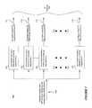
- FIG. 2is a system according to one embodiment of the present subject matter.
- FIG. 3is a high level overview of a frequency channelizer according to one embodiment of the present subject matter.
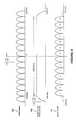
- FIG. 4is a diagram of an input stream to an exemplary frequency channelizer.
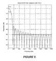
- FIG. 5is a diagram of a FIR window utilized in one embodiment of the present subject matter.
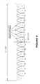
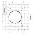
- FIG. 6is a diagram of an exemplary selection of GSM channels at an FFT output.
- FIG. 7is a diagram of a correlator bank according to an embodiment of the present subject matter.
- FIG. 8is a diagram of a floating point and a 1-bit reference signal constellation.
- FIG. 9is a diagram of a floating point and 1-bit reference signal correlation results.
- FIG. 10is a diagram of a peak to average ratio comparison between fixed and floating point references in a simulation.
- FIG. 11is a diagram of a peak to median ratio comparison between fixed and floating point references in a simulation.
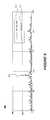
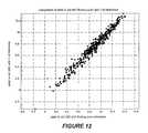
- FIG. 12is a diagram of a peak to standard ratio comparison between fixed and floating point references in a simulation.
- FIG. 13is a diagram of TOA estimation with a floating point and 1-bit reference.
- FIGS. 14 a - care diagrams of detection performance of non-coherent addition of an embodiment of the present subject matter.
- FIGS. 15-17are block diagram of algorithms according to embodiments of the present subject matter.
- FIG. 2is a system according to one embodiment of the present subject matter.
- an exemplary Global System for Mobile communications (“GSM”) network 10may include a network and switching sub-system (“NSS”) 12 , connecting with plural base station subsystems (“BSS”) 14 .
- the BSSs 14generally provide radio communication with mobile devices or stations (“MS”) 16 .
- the NSS 12may communicate with a fixed public network 18 , i.e., a public switched telephone network (“PSTN”) and an integrated services digital network (“ISDN”).
- PSTNpublic switched telephone network
- ISDNintegrated services digital network
- the NSS 12may also include mobile switching centers (“MSC”) 20 interconnected by dedicated connections or via the network 10 .
- MSCs 20may be gateway mobile switching centers (“GMSC”) 22 , which generally handle calls directed to MSs 16 from outside of the network 10 .
- GMSCgateway mobile switching centers
- Each MSC 20may be connected to one or more of the BSSs 14 , and the interface between a BSS 14 and its MSC 20 is standardized.
- the network 10may also include a Geolocation Control Station (“GCS”) 30 .
- GCSGeolocation Control Station
- the GCS 30may, in some embodiments, be independent of the network 10 .
- Each BSS 14may includes a base station controller (“BSC”) 24 connected via an A interface to the MSC 20 .
- the BSC 24generally controls a plurality of base transceiver stations (“BTS”) 26 .
- BTSbase transceiver stations
- Plural BTSs 26may be located at each site and include radio transmitters and receivers for providing radio coverage of a local area or cell so that communication can be established with MSs 16 across a radio interface.
- BTSs 26may also include co-located LMUs. Of course, these LMUs may be sparsely located within an exemplary network and may not be co-located with a respective BTS 26 .
- GSMGlobal System for Mobile Communications
- GPSGlobal Positioning Satellite
- GPSis one of many possible positioning techniques that may be utilized in accordance with embodiments of the present subject matter.
- Other positioning techniques that may be utilized in accordance with embodiments of the present subject matterinclude, but are not limited to, TDOA, AOA, TOA, as well as any number of other geographical positioning techniques.
- TDOATime Division Multiple Access
- AOAAOA
- TOATOA
- any number of other geographical positioning techniquesinclude, but are not limited to, TDOA, AOA, TOA, as well as any number of other geographical positioning techniques.
- GSM normal burstscontain a 26 bit long reference signal or training sequence.
- Embodiments of the present subject mattermay continuously correlate every slot of every frequency against all possible reference signals and store the correlation results in an exemplary database.
- Positioning informationsuch as but not limited to TOA, may be determined by looking up the stored results as soon as tipping information becomes available; thus, no additional collection time is required thereby resulting in low overhead in an exemplary network.
- embodiments of the present subject mattermay non-coherently add the stored correlation results of multiple transmitted slots to thereby boost detection gain and eliminate the necessity of exchanging the demodulated bits through the GCS.
- estimating positioning informationis a lookup operation in embodiments of the present subject matter, a multitude of calls per second may be located. Additionally, mobile appliances or devices may be located after a call is terminated thereby increasing the attractiveness of embodiments of the present subject matter for security applications.
- An LMUmay continuously correlate any or all GSM channels with any or all of the eight possible training sequences, may store the correlation results for a predetermined amount of time, and may effectively compute positioning information of all the transmissions in a network.
- an exemplary GSM network 10may provide information about the most recent transmissions from that mobile device.
- MT-LRmobile terminating—location request
- the network 10may provide information regarding future transmissions.
- Exemplary network tipping informationmay include, but is not limited to, frequencies or channel numbers of a predetermined number of transmissions, e.g., the last few, of a mobile device, an approximate time of several, e.g., the last few, transmissions of a mobile device, training sequences utilized in several, e.g., the last few, transmissions of a mobile device, and combinations thereof.
- the LMUmay look up the matching correlation results stored in the memory, time align the slots and non-coherently add the correlation results. A peak and/or peak quality may be detected which may then be provided to the GCS. The GCS may then provide the positioning information to a positioning determining entity to produce a location fix of the mobile device.
- One embodiment of the present subject mattermay utilize a fast Fourier transform (“FFT”) frequency channelization technique described in Digital Techniques for Wideband Receivers, James Tsui, 1995, the entirety of which is incorporated herein by reference.
- FFTfast Fourier transform
- Those skilled in the artwill appreciate that the present subject matter described herein is not limited for use with only one technique.
- a decimation techniquemay also be utilized with embodiments of the present subject matter, however, depending upon the digital signal processor (“DSP”) employed in an embodiment, one technique may be more computationally efficient than another.
- FIG. 3is a high level overview of a frequency channelizer according to one embodiment of the present subject matter.
- input data 310 to the frequency channelizer 300may be sampled at a predetermined sample rate, such as, but not limited to, 3.2 MHz.
- the sample ratehas an effect on the FFT size, frequency bin separation, overlapping rate of the Short Term Fourier Transform (“STFT”), and number of channels that the input signal may contain.
- STFTShort Term Fourier Transform
- 3.2 MHzmay be a suitable sampling rate
- 1.6 MHzmay be a suitable sampling rate.
- these sampling ratesare exemplary only and should not limit the scope of the claims appended herewith.
- FIG. 4is a diagram of an input stream to an exemplary frequency channelizer.
- an input signal 410 to a DSPmay be aligned to capture a predetermined number of GSM channels 420 .
- the GSM channels 420 illustrated in FIG. 4are only a few of the 125 available GSM channels.
- an RF front end and an IF section of an exemplary receivermay provide a baseband signal to exemplary circuitry of embodiments of the present subject matter, and the GSM channels 420 illustrated in FIG. 4 may thus be depicted as baseband signals.
- the Programmable Downconvertercan be configured to align the spectrum of the input signal 410 to a DSP to capture, for example, fourteen GSM channels.
- the PDCmay be viewed as a device having the illustrated frequency response 430 in FIG. 4 . Therefore, when the signal 420 passes through the PDC, an output from the DSP has the spectrum shown in 410 which illustrates that a few (in this case fourteen) GSM channels may be preserved the remainder filtered out.
- a block of thirty two input samples 311may be windowed by a finite impulse response (“FIR”) or other suitable filter 320 .
- FIRfinite impulse response
- One suitable filtermay be, but is not limited to, a 32-tap FIR filter.
- the thirty two windowed samples 322may then be passed to an Inverse Fast Fourier Transform (“IFFT”) block 330 .
- IFFTInverse Fast Fourier Transform
- the output of the IFFT block 330 at bins 1 , 3 , 5 , 7 , 9 , 11 , 13 , 19 , 21 , 23 , 25 , 27 , 29 , and 31may generally represent the sample streams of the 14 input GSM channels 410 depicted in FIG. 4 .
- a second block of input data 312may be selected with, for example, a 75% overlap, meaning that the input block 312 may slide by 8 samples. Additional input blocks 313 , 314 , 315 and so on may be continuously processed accordingly.
- FIGS. 5 and 6generally illustrate how one exemplary frequency channelization technique may be implemented.
- FIG. 5is a diagram of a FIR window utilized in one embodiment of the present subject matter.
- an exemplary 32-tap windowmay employ a frequency response that passes a single GSM channel at the baseband and stops all other channels.
- An optimum filter responsemay generally be determined by simulation, and the example of the window illustrated in FIG. 5 is exemplary only and was simulated utilizing a least square linear-phase FIR filter design.
- FIG. 6is a diagram of an exemplary selection of GSM channels at the FFT output 332 which generally represents the sample streams of the 14 input GSM channels 410 depicted in FIG. 4 . These outputs 332 may then be provided to one or more exemplary correlators 334 .
- FIG. 7is a diagram of a correlator bank according to an embodiment of the present subject matter.
- each of the channelized outputs 332may be correlated with eight training sequences.
- An exemplary Communication Logic Unit (“CLU”) of a DSPe.g, TigerSHARC processor, may provide an efficient method of correlation.
- CLUCommunication Logic Unit
- a correlator bank 700may comprise one or more correlators 701 - 708 processing data in 16-bit or 32-bit complex I/Q format.
- Complex samples 332 from the IFFT block 330may be provided at a 400 KHz rate representing a 200 KHz channel.
- the CLU based correlator bank 700may take, for example, input samples and correlate this with a 2-bit (one bit for each of the real and imaginary parts) reference signal (training sequence 0 through 7 ). This correlated output 711 - 718 may then be provided to a database 720 or other suitable memory. Simulation of one embodiment of the present subject matter showed that a 2-bit signal provided adequate correlation performance.
- FIG. 8is a diagram of a floating point and 1-bit reference signal constellation.
- a floating point 802 and 1-bit fixed point reference signal 804 constellationwas plotted 800 .
- High precision signal points in the first, second, third and fourth quadrants 811 - 814map to the fixed point signal 1+j, ⁇ 1+j, ⁇ 1 ⁇ j, and 1 ⁇ j, respectively.
- a maximum phase error in the quantization processesmay generally be ⁇ /4 with an average error much less than that considering that signal points tend to have higher density around it ⁇ /4, 3 ⁇ /4, 5 ⁇ /4, and 7 ⁇ /4 angles.
- FIG. 9is a diagram of floating point and 1-bit reference signal correlation results.
- an exemplary correlation output 900 for a floating point 902 and 1-bit fixed point 904 referencewas simulated.
- a fixed point peak 910appears higher because of scaling; however, the respective peak to average ratio or peak to standard ratio was actually lower than those of the floating point.
- FIG. 10is a diagram of a peak to average ratio comparison between fixed and floating point references in the simulation
- FIG. 11is a diagram of a peak to median ratio comparison between fixed and floating point references in the simulation
- FIG. 12is a diagram of a peak to standard deviation ratio comparison between fixed and floating point references in the simulation
- FIG. 13is a diagram of TOA estimation with a floating point and 1-bit reference.
- Exemplary CLUsmay provide powerful correlation utilities if a 1-bit reference is utilized; the CLU may compute up to 128 complex multiplies and 128 complex additions (accumulations) in a single cycle. As peak detection and TOA estimation performance with a 1-bit reference is comparable to that of a floating point reference, a CLU based correlation technique may be implemented in certain non-limiting embodiments of the present subject matter.
- a training sequencemay generally be around 17.5% of an entire burst, and correlation gain using the training sequence of one burst may not be adequate for signal detection in secondary sites.
- An existing GSM systemafter demodulation in the primary site, may utilize the whole burst as a reference.
- an increase of around 7.55 dB processing gainmay be employed. This processing gain may be achieved through non-coherent addition of multiple transmitted slots. For example, approximately ten non-coherent additions may be employed in certain embodiments to increase the processing gain.
- FIGS. 14 a - care diagrams of detection performance of non-coherent addition of an embodiment of the present subject matter.
- the channelswere provided with equal power and significant ISI existed between channels.
- ten non-coherent additionsgenerally provide adequate processing gain for an embodiment of the present subject matter.
- the correlation data of different slotsmay be delayed by fractional samples to align them.
- a Lagrange interpolation filter having a small number of tapsmay also be employed for delay adjustment.
- one embodimentmay employ an extended precision CLU xcorr instruction for correlation to avoid rearranging data into a 16-bit I/Q packed complex format.
- An exemplary extended precision instructionmay also reduce risk of overflow and underflow and may make scaling easier with fixed point implementation.
- eight correlation output valuesmay be available after the correlation operation.
- a minimum processing block durationmay be eight samples at 400 KHz.
- thisis exemplary only and should not limit the scope of the claims appended herewith as one of skill in the art would note that any reasonable length of data that is a multiple of eight may be employed.
- every thirty two input data points, packed in a 32-bit I/Q complex format,may be windowed by a 32 point real filter or other suitable filter as the first step.
- the following assembly instructionmay be employed: ⁇ X
- the above instruction (1)may multiply a complex input with 16-bit (32-bit I/Q packed, with Q part set to zero) real coefficients and may transfer the result into a register in a single cycle; thus, the minimum cycle count for filtering may be 32 cycles. These 32 complex samples may then go through the FFT block and produce 32 output samples, each of which may represent a sample at 400 KHz.
- the cycle count for fixed point FFTmay vary from 2.2 to 3 cycles per tap, and it is estimated that approximately 80 cycles may be necessary for a 32 point FFT in this non-limiting embodiment.
- one realistic cycle count estimatemay be 4480 cycles for one channelizer according to an embodiment of the present subject matter.
- Correlation and squaring operations for two sequenceswere implemented in one embodiment at the same time using two (X and Y) compute blocks. In this implementation, it was observed that 62 cycles were utilized to obtain eight correlation output for two sequences, meaning a cycle count of 31 cycles per sequence.
- Tasks that were accomplished within the 62 cycles included: read 40+848 complex input data samples from internal memory buffer; read two pre-computed reference signal (modulated training sequence) from internal memory and load the THR registers; correlate 48 complex input samples with 40 reference samples and obtain 8 correlation output for each of the two sequences; transfer the correlation output from the CLU's TR registers into compute block registers; perform I 2 +Q 2 operations on the correlation output; and save the 16 values (8 for each sequence) in a buffer in the internal memory so that a DMA process may ship them out to external memory later; to name a few.
- the outputsare 32-bit integers and generally require four bytes to store.
- this implementationis exemplary only and should not limit the scope of the claims appended herewith.
- FIG. 15is a block diagram of an algorithm according to one embodiment of the present subject matter.
- a method 1500 for estimating a location of wireless devices transmitting signals on channels in a communications system having a plurality of nodes and a plurality of LMUsis provided.
- a first plurality of signalsmay be received from a first channel by one or more of the plural LMUs
- a second plurality of signalsmay be received from a second channel by one or more of the plural LMUs.
- the received first and second plural signalsmay be converted into first and second digital signals at step 1530 , and at step 1540 divided into first and second sets of frequency bins, the first and second sets of bins corresponding to the respective channel.
- the step of dividingmay further comprise windowing the first and second digital signals and determining an IFFT of each of the windowed signals. This windowing may be performed by a 32-tap FIR filter and these additional steps may be performed in parallel or in series.
- each of the divided signalsmay be correlated with one or more reference signals, such as, but not limited to, training sequences. In one embodiment, this correlation may be a continuous correlation with eight training sequences.
- the correlated signalsmay then be stored at step 1560 in a database for estimating a location of one or more wireless devices. In another embodiment, the method may include estimating a location of the wireless device as a function of the stored correlated signals.
- One embodimentmay include receiving tipping information by one or more of the LMUs wherein data used for the stored correlated signals was received prior to receipt of the tipping information.
- Exemplary tipping informationmay be, but is not limited to, frequencies or channel numbers of transmissions from the wireless device, approximate time of one or more transmissions from the wireless device, training sequences utilized in one or more transmissions from the wireless device, and combinations thereof.
- Another embodimentmay locate the wireless device after it has ceased transmitting signals on its respective channel and when the step of estimating a location occurs after the cease of transmission.
- An additional embodimentmay include the steps of receiving tipping information by one or more of the LMUs, retrieving stored correlated signals from the database matching data in the tipping information, non-coherently adding the retrieved signals, determining TOA information as a function of peak or peak quality of the added signals, and estimating a location of a wireless device as a function of the determined TOA information.
- FIG. 16is a block diagram of an algorithm according to another embodiment of the present subject matter.
- a method 1600 for estimating a location of a wireless device in a communication system having a plurality of nodes and a plurality of LMUsis provided.
- tipping information corresponding to the wireless devicemay be received by ones of the plural LMUs.
- the wireless devicemay be located as a function of signals transmitted from the wireless device prior to receipt of the tipping information.
- step 1620may further include converting transmitted signals from the wireless device into digital signals, dividing the digital signals into a set of frequency bins corresponding to a channel upon which the wireless device transmitted, correlating the divided signals with one or more training sequences, and storing correlated signals in a database for use in the location of the wireless device.
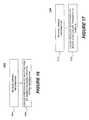
- FIG. 17is a block diagram of an algorithm according to a further embodiment of the present subject matter.
- a method 1700 for estimating a location of a wireless device transmitting signals on a channel in a communication system having a plurality of nodes and a plurality of LMUsis provided.
- tipping informationmay be received by ones of the plural LMUs, the tipping information corresponding to the wireless device.
- a location of the wireless devicemay be determined as a function of the tipping information when the device is no longer transmitting signals.
- step 1720may further include converting transmitted signals from the wireless device into digital signals, dividing the digital signals into a set of frequency bins corresponding to a channel upon which the wireless device transmitted, correlating the divided signals with one or more training sequences, and storing correlated signals in a database for use in the location of the wireless device.
- a further embodimentmay include the steps of retrieving stored signals from a database that match data in the tipping information with the wireless device, non-coherently adding the retrieved signals, determining TOA information as a function of peak or peak quality of the added signals, and determining a location of a wireless device as a function of the determined TOA information.
- FIGS. 15-17illustrate high-level logic flow diagrams for exemplary process steps for implementing the method and system of the present subject matter. These steps are those requiring a physical manipulation of physical quantities. Usually, although not necessarily, these quantities take the form of electrical or magnetic signals capable of being stored, transmitted, combined, compared, and otherwise manipulated. It has proven convenient at times by those skilled in the art, to refer to these signals as bits, values, elements, symbols, characters, terms, numbers, or the like. It should be borne in mind, however, that all of these and similar terms are to be associated with the appropriate physical quantities and are merely convenient labels applied to these quantities.
- the manipulations performedare often referred to in terms, such as “receiving,” “transmitting,” “determining,” “storing,” and the like, may commonly be associated with mental or physical operations performed by a human operator; however, no such capability of a human operator is possible or desirable in most cases of the operations described herein. As indicated herein, these operations are primarily machine operations.
- Useful machines for performing operations of a preferred embodiment of the present subject matterinclude data-processing systems.
- the present subject matter relating to method steps for processing electrical or other physical signals to generate other desired signalscan generally be implemented via a computer or microcomputer. However, it is not necessary to maintain within a computer memory of a mobile telephone subscriber unit, instructions implementing these method steps. Such instructions can be maintained within a computer memory location of a wireless telephone base station or at a central center from which such base stations receive instructions.
- the methods described hereincan be implemented as a program product (e.g., a control program residing in a computer memory) containing instructions that when executed on a processor, carry out the operations depicted in the logic diagrams of FIGS. 15-17 . While the present subject matter is described in the context of a fully functional system, those skilled in the art will further appreciate that the present subject matter is capable of being distributed as a program product in a variety of forms, and that the present subject matter applies equally, regardless of the particular type of signal-bearing media utilized to actually carry out the distribution. Examples of signal-bearing media include recordable-type media, such as floppy disks, hard-disk drives and CD ROMs, and transmission-type media, such as digital and analog communication links.
- signal-bearing mediainclude recordable-type media, such as floppy disks, hard-disk drives and CD ROMs, and transmission-type media, such as digital and analog communication links.
Landscapes
- Engineering & Computer Science (AREA)
- Computer Networks & Wireless Communication (AREA)
- Signal Processing (AREA)
- Mobile Radio Communication Systems (AREA)
Abstract
Description
{X|Y|XY}Rs=MRa, MRa+=Rm**Rn{({I}{C}{J})} (1)
Claims (13)
Priority Applications (2)
| Application Number | Priority Date | Filing Date | Title |
|---|---|---|---|
| US12/563,590US8340683B2 (en) | 2009-09-21 | 2009-09-21 | System and method for a high throughput GSM location solution |
| US13/610,182US8463293B2 (en) | 2009-09-21 | 2012-09-11 | System and method for a high throughput GSM location solution |
Applications Claiming Priority (1)
| Application Number | Priority Date | Filing Date | Title |
|---|---|---|---|
| US12/563,590US8340683B2 (en) | 2009-09-21 | 2009-09-21 | System and method for a high throughput GSM location solution |
Related Child Applications (1)
| Application Number | Title | Priority Date | Filing Date |
|---|---|---|---|
| US13/610,182ContinuationUS8463293B2 (en) | 2009-09-21 | 2012-09-11 | System and method for a high throughput GSM location solution |
Publications (2)
| Publication Number | Publication Date |
|---|---|
| US20110070892A1 US20110070892A1 (en) | 2011-03-24 |
| US8340683B2true US8340683B2 (en) | 2012-12-25 |
Family
ID=43757063
Family Applications (2)
| Application Number | Title | Priority Date | Filing Date |
|---|---|---|---|
| US12/563,590Expired - Fee RelatedUS8340683B2 (en) | 2009-09-21 | 2009-09-21 | System and method for a high throughput GSM location solution |
| US13/610,182Expired - Fee RelatedUS8463293B2 (en) | 2009-09-21 | 2012-09-11 | System and method for a high throughput GSM location solution |
Family Applications After (1)
| Application Number | Title | Priority Date | Filing Date |
|---|---|---|---|
| US13/610,182Expired - Fee RelatedUS8463293B2 (en) | 2009-09-21 | 2012-09-11 | System and method for a high throughput GSM location solution |
Country Status (1)
| Country | Link |
|---|---|
| US (2) | US8340683B2 (en) |
Cited By (1)
| Publication number | Priority date | Publication date | Assignee | Title |
|---|---|---|---|---|
| US9910132B2 (en)* | 2014-11-10 | 2018-03-06 | The Boeing Company | Systems and methods for coherent signal fusion for time and frequency estimation |
Families Citing this family (2)
| Publication number | Priority date | Publication date | Assignee | Title |
|---|---|---|---|---|
| CN110022523B (en)* | 2018-01-05 | 2022-04-12 | 华为技术有限公司 | Method, device and system for terminal equipment positioning |
| US12052121B2 (en)* | 2020-09-01 | 2024-07-30 | Qualcomm Incorporated | Neural network based line of sight detection and angle estimation for positioning |
Citations (53)
| Publication number | Priority date | Publication date | Assignee | Title |
|---|---|---|---|---|
| US4728959A (en) | 1986-08-08 | 1988-03-01 | Ventana Sciences Inc. | Direction finding localization system |
| US5327144A (en) | 1993-05-07 | 1994-07-05 | Associated Rt, Inc. | Cellular telephone location system |
| US5883929A (en)* | 1996-04-03 | 1999-03-16 | Ericsson, Inc. | Synchronization method, and associated circuitry, for synchronizing a receiver with a transmitter |
| US5959580A (en) | 1994-11-03 | 1999-09-28 | Ksi Inc. | Communications localization system |
| US6009334A (en) | 1997-11-26 | 1999-12-28 | Telefonaktiebolaget L M Ericsson | Method and system for determining position of mobile radio terminals |
| US6031490A (en) | 1997-08-18 | 2000-02-29 | Telefonaktiebolaget L M Ericsson | Method and system for determining the position of mobile radio terminals |
| US6047192A (en) | 1996-05-13 | 2000-04-04 | Ksi Inc. | Robust, efficient, localization system |
| US6091362A (en) | 1999-01-08 | 2000-07-18 | Trueposition, Inc. | Bandwidth synthesis for wireless location system |
| US6101178A (en) | 1997-07-10 | 2000-08-08 | Ksi Inc. | Pseudolite-augmented GPS for locating wireless telephones |
| US6108555A (en) | 1996-05-17 | 2000-08-22 | Ksi, Inc. | Enchanced time difference localization system |
| US6275186B1 (en)* | 1998-12-10 | 2001-08-14 | Samsung Electronics Co., Ltd. | Device and method for locating a mobile station in a mobile communication system |
| US6295454B1 (en) | 1999-03-18 | 2001-09-25 | Ericsson Inc. | System and method for providing chronicled location information for terminal-based position calculation |
| US6334059B1 (en) | 1999-01-08 | 2001-12-25 | Trueposition, Inc. | Modified transmission method for improving accuracy for e-911 calls |
| US6366241B2 (en) | 2000-06-26 | 2002-04-02 | Trueposition, Inc. | Enhanced determination of position-dependent signal characteristics of a wireless transmitter |
| US6388618B1 (en) | 1999-01-08 | 2002-05-14 | Trueposition, Inc. | Signal collection system for a wireless location system |
| US6463290B1 (en) | 1999-01-08 | 2002-10-08 | Trueposition, Inc. | Mobile-assisted network based techniques for improving accuracy of wireless location system |
| US20020160788A1 (en) | 2001-02-23 | 2002-10-31 | Duffett-Smith Peter James | Positioning systems and methods |
| US6522887B2 (en) | 1998-07-27 | 2003-02-18 | Telefonaktiebolaget Lm Ericsson (Publ) | Identifying starting time for making time of arrival measurements |
| US6529708B1 (en) | 1999-07-16 | 2003-03-04 | Telefonaktiebolaget Lm Ericsson (Publ) | Efficient determination of time of arrival of radio communication bursts |
| US6646604B2 (en) | 1999-01-08 | 2003-11-11 | Trueposition, Inc. | Automatic synchronous tuning of narrowband receivers of a wireless location system for voice/traffic channel tracking |
| US6675018B2 (en) | 1999-01-09 | 2004-01-06 | Motorola, Inc. | Method of and system for estimating a time of arrival of a radio signal |
| US6687507B2 (en) | 2000-05-03 | 2004-02-03 | Telefonaktiebolaget Lm Ericsson (Publ) | Time of arrival estimation for edge/GSM |
| US20040075562A1 (en)* | 2002-10-11 | 2004-04-22 | Thomas Land | Zone detection locator |
| US6765531B2 (en) | 1999-01-08 | 2004-07-20 | Trueposition, Inc. | System and method for interference cancellation in a location calculation, for use in a wireless location system |
| US6782264B2 (en) | 1999-01-08 | 2004-08-24 | Trueposition, Inc. | Monitoring of call information in a wireless location system |
| US6873290B2 (en) | 1999-01-08 | 2005-03-29 | Trueposition, Inc. | Multiple pass location processor |
| US6876859B2 (en) | 2001-07-18 | 2005-04-05 | Trueposition, Inc. | Method for estimating TDOA and FDOA in a wireless location system |
| US6889052B2 (en) | 2002-08-30 | 2005-05-03 | Motorola, Inc. | Method and apparatus for generating time of arrival estimates for use in determining a location |
| US20060003775A1 (en) | 1999-01-08 | 2006-01-05 | Bull Jeffrey F | Advanced triggers for location-based service applications in a wireless location system |
| US6996392B2 (en) | 2002-09-03 | 2006-02-07 | Trueposition, Inc. | E911 overlay solution for GSM, for use in a wireless location system |
| US20060093048A9 (en)* | 2003-12-19 | 2006-05-04 | Anisse Taleb | Partial Spectral Loss Concealment In Transform Codecs |
| US7085248B1 (en) | 1999-07-05 | 2006-08-01 | Nokia Networks Oy | Method of identifying information addressed to a user in a communication system and a communication system |
| WO2006088472A1 (en) | 2005-02-11 | 2006-08-24 | Trueposition, Inc. | Base transceiver station (bts) synchronization |
| US20070111746A1 (en) | 2005-11-16 | 2007-05-17 | Anderson Robert J | Transmit-power control for wireless mobile services |
| US20070155401A1 (en) | 2005-12-30 | 2007-07-05 | Trueposition Inc. | User plane uplink time difference of arrival (u-tdoa) |
| US20070155489A1 (en) | 2005-12-30 | 2007-07-05 | Frederic Beckley | Device and network enabled geo-fencing for area sensitive gaming enablement |
| US7315745B2 (en) | 2002-08-28 | 2008-01-01 | Cambridge Positioning Systems Ltd. | Radio positioning systems |
| US20080132244A1 (en) | 2006-12-01 | 2008-06-05 | Trueposition, Inc. | Subscriptionless location of wireless devices |
| US20080132247A1 (en) | 2006-12-01 | 2008-06-05 | Trueposition, Inc. | System for automatically determining cell transmitter parameters to facilitate the location of wireless devices |
| US20080137524A1 (en) | 2006-12-12 | 2008-06-12 | Trueposition, Inc. | Location of Wideband OFDM Transmitters With Limited Receiver Bandwidth |
| US20080160952A1 (en) | 2006-12-28 | 2008-07-03 | Trueposition, Inc. | Emergency wireless location system including a location determining receiver |
| US20080160953A1 (en) | 2006-12-28 | 2008-07-03 | Trueposition, Inc. | Emergency wireless location system including a wireless transceiver |
| US20080158059A1 (en) | 2006-12-27 | 2008-07-03 | Trueposition, Inc. | Portable, iterative geolocation of RF emitters |
| US7427952B2 (en) | 2005-04-08 | 2008-09-23 | Trueposition, Inc. | Augmentation of commercial wireless location system (WLS) with moving and/or airborne sensors for enhanced location accuracy and use of real-time overhead imagery for identification of wireless device locations |
| US20080248811A1 (en) | 2003-12-30 | 2008-10-09 | Trueposition, Inc. | TDOA/GPS Hybrid Wireless Location System |
| US20080261612A1 (en) | 2007-04-18 | 2008-10-23 | Mia Rashidus S | Sparsed U-TDOA Wireless Location Networks |
| US20080261611A1 (en) | 2007-04-18 | 2008-10-23 | Mia Rashidus S | Sparsed U-TDOA Wireless Location Networks |
| US20080261613A1 (en) | 2007-04-18 | 2008-10-23 | Anderson Robert J | Sparsed U-TDOA Wireless Location Networks |
| US20080261614A1 (en) | 2007-04-18 | 2008-10-23 | Mia Rashidus S | Sparsed U-TDOA Wireless Location Networks |
| US20090005061A1 (en) | 2005-12-30 | 2009-01-01 | Trueposition, Inc. | Location quality of service indicator |
| US20090060207A1 (en)* | 2004-04-16 | 2009-03-05 | Dublin Institute Of Technology | method and system for sound source separation |
| US7593738B2 (en) | 2005-12-29 | 2009-09-22 | Trueposition, Inc. | GPS synchronization for wireless communications stations |
| US20100039326A1 (en) | 2008-08-15 | 2010-02-18 | Trueposition, Inc. | Variable Coherence Integration for the Location of Weak Signals |
Family Cites Families (28)
| Publication number | Priority date | Publication date | Assignee | Title |
|---|---|---|---|---|
| US5251233A (en)* | 1990-12-20 | 1993-10-05 | Motorola, Inc. | Apparatus and method for equalizing a corrupted signal in a receiver |
| US5717713A (en)* | 1994-11-18 | 1998-02-10 | Stanford Telecommunications, Inc. | Technique to permit rapid acquisition and alert channel signalling for base station-to-user link of an orthogonal CDMA (OCDMA) communication system |
| JP2845228B2 (en) | 1996-12-10 | 1999-01-13 | 日本電気株式会社 | Neighbor cell synchronization detection method |
| US6115605A (en) | 1997-08-29 | 2000-09-05 | Ppm, Inc. | Communication system and device using dynamic receiver addressing |
| US6108558A (en) | 1998-04-21 | 2000-08-22 | Motorola, Inc. | Method for calculating a location of a remote Unit utilizing observed time difference (OTD) and real time difference (RTD) measurements. |
| US6449486B1 (en) | 1998-05-27 | 2002-09-10 | Polaris Wireless, Inc. | Multiple location estimates in a cellular communication system |
| US6393294B1 (en) | 1998-09-22 | 2002-05-21 | Polaris Wireless, Inc. | Location determination using RF fingerprinting |
| US7257414B2 (en) | 1998-09-22 | 2007-08-14 | Polaris Wireless, Inc. | Estimating the Location of a Wireless Terminal Based on Non-Uniform Probabilities of Movement |
| US7734298B2 (en) | 1998-09-22 | 2010-06-08 | Polaris Wireless, Inc. | Estimating the location of a wireless terminal based on signal path impairment |
| US7899467B2 (en) | 1998-09-22 | 2011-03-01 | Polaris Wireless, Inc. | Estimating the location of a wireless terminal based on the traits of the multipath components of a signal |
| US6269246B1 (en) | 1998-09-22 | 2001-07-31 | Ppm, Inc. | Location determination using RF fingerprinting |
| US6944465B2 (en) | 1998-09-22 | 2005-09-13 | Polaris Wireless, Inc. | Estimating the location of a mobile unit based on the elimination of improbable locations |
| US7433695B2 (en) | 2002-11-18 | 2008-10-07 | Polaris Wireless, Inc. | Computationally-efficient estimation of the location of a wireless terminal based on pattern matching |
| US6978124B2 (en) | 2002-12-11 | 2005-12-20 | Motorola, Inc. | Method and mobile station for autonomously determining an angle of arrival (AOA) estimation |
| US7460505B2 (en) | 2003-02-04 | 2008-12-02 | Polaris Wireless, Inc. | Location estimation of wireless terminals through pattern matching of signal-strength differentials |
| US7233799B2 (en) | 2003-02-24 | 2007-06-19 | Polaris Wireless, Inc. | Location estimation of wireless terminals based on combinations of signal strength measurements and geometry-of-arrival measurements |
| US7250907B2 (en) | 2003-06-30 | 2007-07-31 | Microsoft Corporation | System and methods for determining the location dynamics of a portable computing device |
| US7116987B2 (en) | 2003-07-19 | 2006-10-03 | Polaris Wireless, Inc. | Location estimation of wireless terminals through pattern matching of deduced and empirical signal-strength measurements |
| US7433652B2 (en) | 2005-03-07 | 2008-10-07 | Polaris Wireless, Inc. | Electro-magnetic propagation modeling |
| US7796966B2 (en) | 2005-03-15 | 2010-09-14 | Polaris Wireless, Inc. | Estimating the location of a wireless terminal based on calibrated signal-strength measurements |
| US7753278B2 (en) | 2006-05-22 | 2010-07-13 | Polaris Wireless, Inc. | Estimating the location of a wireless terminal based on non-uniform locations |
| US8073463B2 (en)* | 2008-10-06 | 2011-12-06 | Andrew, Llc | System and method of UMTS UE location using uplink dedicated physical control channel and downlink synchronization channel |
| US8331500B2 (en)* | 2009-05-13 | 2012-12-11 | Lg Electronics Inc. | Transmitting/receiving system and method of processing broadcast signal in transmitting/receiving system |
| US8559564B2 (en)* | 2009-05-21 | 2013-10-15 | Lg Electronics Inc. | Transmitting/receiving system and method of processing broadcast signal in transmitting/receiving system |
| US8106817B2 (en) | 2009-12-31 | 2012-01-31 | Polaris Wireless, Inc. | Positioning system and positioning method |
| US8106818B2 (en) | 2009-12-31 | 2012-01-31 | Polaris Wireless, Inc. | Positioning system and positioning method |
| US8013785B2 (en) | 2009-12-31 | 2011-09-06 | Ntt Docomo, Inc. | Positioning system and positioning method |
| US8155394B2 (en) | 2010-07-13 | 2012-04-10 | Polaris Wireless, Inc. | Wireless location and facial/speaker recognition system |
- 2009
- 2009-09-21USUS12/563,590patent/US8340683B2/ennot_activeExpired - Fee Related
- 2012
- 2012-09-11USUS13/610,182patent/US8463293B2/ennot_activeExpired - Fee Related
Patent Citations (88)
| Publication number | Priority date | Publication date | Assignee | Title |
|---|---|---|---|---|
| US4728959A (en) | 1986-08-08 | 1988-03-01 | Ventana Sciences Inc. | Direction finding localization system |
| US5327144A (en) | 1993-05-07 | 1994-07-05 | Associated Rt, Inc. | Cellular telephone location system |
| US5608410A (en) | 1993-05-07 | 1997-03-04 | Associated Rt, Inc. | System for locating a source of bursty transmissions cross reference to related applications |
| US6288676B1 (en) | 1994-11-03 | 2001-09-11 | Ksi, Inc. | Apparatus and method for single station communications localization |
| US5959580A (en) | 1994-11-03 | 1999-09-28 | Ksi Inc. | Communications localization system |
| US6288675B1 (en) | 1994-11-03 | 2001-09-11 | Ksi, Inc. | Single station communications localization system |
| US6127975A (en) | 1994-11-03 | 2000-10-03 | Ksi, Incorporated | Single station communications localization system |
| US5883929A (en)* | 1996-04-03 | 1999-03-16 | Ericsson, Inc. | Synchronization method, and associated circuitry, for synchronizing a receiver with a transmitter |
| US6546256B1 (en) | 1996-05-13 | 2003-04-08 | Ksi Inc. | Robust, efficient, location-related measurement |
| US7340259B2 (en) | 1996-05-13 | 2008-03-04 | Ksi Inc. | Robust, efficient, localization system |
| US20080161015A1 (en) | 1996-05-13 | 2008-07-03 | Trueposition, Inc. | Robust, Efficient, Localization System |
| US6047192A (en) | 1996-05-13 | 2000-04-04 | Ksi Inc. | Robust, efficient, localization system |
| US6108555A (en) | 1996-05-17 | 2000-08-22 | Ksi, Inc. | Enchanced time difference localization system |
| US6119013A (en) | 1996-05-17 | 2000-09-12 | Ksi, Inc. | Enhanced time-difference localization system |
| US6101178A (en) | 1997-07-10 | 2000-08-08 | Ksi Inc. | Pseudolite-augmented GPS for locating wireless telephones |
| US6771625B1 (en) | 1997-07-10 | 2004-08-03 | Ksi, Inc. | Pseudolite-augmented GPS for locating wireless telephones |
| US6031490A (en) | 1997-08-18 | 2000-02-29 | Telefonaktiebolaget L M Ericsson | Method and system for determining the position of mobile radio terminals |
| US6009334A (en) | 1997-11-26 | 1999-12-28 | Telefonaktiebolaget L M Ericsson | Method and system for determining position of mobile radio terminals |
| US6522887B2 (en) | 1998-07-27 | 2003-02-18 | Telefonaktiebolaget Lm Ericsson (Publ) | Identifying starting time for making time of arrival measurements |
| US6275186B1 (en)* | 1998-12-10 | 2001-08-14 | Samsung Electronics Co., Ltd. | Device and method for locating a mobile station in a mobile communication system |
| US6661379B2 (en) | 1999-01-08 | 2003-12-09 | Trueposition, Inc. | Antenna selection method for a wireless location system |
| US6563460B2 (en) | 1999-01-08 | 2003-05-13 | Trueposition, Inc. | Collision recovery in a wireless location system |
| US6281834B1 (en) | 1999-01-08 | 2001-08-28 | Trueposition, Inc. | Calibration for wireless location system |
| US7271765B2 (en) | 1999-01-08 | 2007-09-18 | Trueposition, Inc. | Applications processor including a database system, for use in a wireless location system |
| US6317604B1 (en) | 1999-01-08 | 2001-11-13 | Trueposition, Inc. | Centralized database system for a wireless location system |
| US6317081B1 (en) | 1999-01-08 | 2001-11-13 | Trueposition, Inc. | Internal calibration method for receiver system of a wireless location system |
| US6334059B1 (en) | 1999-01-08 | 2001-12-25 | Trueposition, Inc. | Modified transmission method for improving accuracy for e-911 calls |
| US6351235B1 (en) | 1999-01-08 | 2002-02-26 | Trueposition, Inc. | Method and system for synchronizing receiver systems of a wireless location system |
| US7023383B2 (en) | 1999-01-08 | 2006-04-04 | Trueposition, Inc. | Multiple pass location processor |
| US6388618B1 (en) | 1999-01-08 | 2002-05-14 | Trueposition, Inc. | Signal collection system for a wireless location system |
| US6400320B1 (en) | 1999-01-08 | 2002-06-04 | Trueposition, Inc. | Antenna selection method for a wireless location system |
| US6463290B1 (en) | 1999-01-08 | 2002-10-08 | Trueposition, Inc. | Mobile-assisted network based techniques for improving accuracy of wireless location system |
| US20060030333A1 (en) | 1999-01-08 | 2006-02-09 | Ward Matthew L | Geo-fencing in a wireless location system |
| US6483460B2 (en) | 1999-01-08 | 2002-11-19 | Trueposition, Inc. | Baseline selection method for use in a wireless location system |
| US20020172223A1 (en) | 1999-01-08 | 2002-11-21 | Stilp Louis A. | Calibration for wireless location system |
| US6492944B1 (en) | 1999-01-08 | 2002-12-10 | Trueposition, Inc. | Internal calibration method for receiver system of a wireless location system |
| US6519465B2 (en) | 1999-01-08 | 2003-02-11 | Trueposition, Inc. | Modified transmission method for improving accuracy for E-911 calls |
| US6266013B1 (en) | 1999-01-08 | 2001-07-24 | Trueposition, Inc. | Architecture for a signal collection system of a wireless location system |
| US20060003775A1 (en) | 1999-01-08 | 2006-01-05 | Bull Jeffrey F | Advanced triggers for location-based service applications in a wireless location system |
| US20030064734A1 (en) | 1999-01-08 | 2003-04-03 | Trueposition, Inc. | Modified transmission method for improving accuracy for E-911 calls |
| US6184829B1 (en) | 1999-01-08 | 2001-02-06 | Trueposition, Inc. | Calibration for wireless location system |
| US7167713B2 (en) | 1999-01-08 | 2007-01-23 | Trueposition, Inc. | Monitoring of call information in a wireless location system |
| US6603428B2 (en) | 1999-01-08 | 2003-08-05 | Trueposition, Inc. | Multiple pass location processing |
| US6646604B2 (en) | 1999-01-08 | 2003-11-11 | Trueposition, Inc. | Automatic synchronous tuning of narrowband receivers of a wireless location system for voice/traffic channel tracking |
| US6172644B1 (en) | 1999-01-08 | 2001-01-09 | Trueposition, Inc. | Emergency location method for a wireless location system |
| US6097336A (en) | 1999-01-08 | 2000-08-01 | Trueposition, Inc. | Method for improving the accuracy of a wireless location system |
| US6285321B1 (en) | 1999-01-08 | 2001-09-04 | Trueposition, Inc. | Station based processing method for a wireless location system |
| US6091362A (en) | 1999-01-08 | 2000-07-18 | Trueposition, Inc. | Bandwidth synthesis for wireless location system |
| US6765531B2 (en) | 1999-01-08 | 2004-07-20 | Trueposition, Inc. | System and method for interference cancellation in a location calculation, for use in a wireless location system |
| US6115599A (en) | 1999-01-08 | 2000-09-05 | Trueposition, Inc. | Directed retry method for use in a wireless location system |
| US6782264B2 (en) | 1999-01-08 | 2004-08-24 | Trueposition, Inc. | Monitoring of call information in a wireless location system |
| US6873290B2 (en) | 1999-01-08 | 2005-03-29 | Trueposition, Inc. | Multiple pass location processor |
| US6675018B2 (en) | 1999-01-09 | 2004-01-06 | Motorola, Inc. | Method of and system for estimating a time of arrival of a radio signal |
| US6295454B1 (en) | 1999-03-18 | 2001-09-25 | Ericsson Inc. | System and method for providing chronicled location information for terminal-based position calculation |
| US7085248B1 (en) | 1999-07-05 | 2006-08-01 | Nokia Networks Oy | Method of identifying information addressed to a user in a communication system and a communication system |
| US6529708B1 (en) | 1999-07-16 | 2003-03-04 | Telefonaktiebolaget Lm Ericsson (Publ) | Efficient determination of time of arrival of radio communication bursts |
| US6687507B2 (en) | 2000-05-03 | 2004-02-03 | Telefonaktiebolaget Lm Ericsson (Publ) | Time of arrival estimation for edge/GSM |
| US6366241B2 (en) | 2000-06-26 | 2002-04-02 | Trueposition, Inc. | Enhanced determination of position-dependent signal characteristics of a wireless transmitter |
| US20020160788A1 (en) | 2001-02-23 | 2002-10-31 | Duffett-Smith Peter James | Positioning systems and methods |
| US6876859B2 (en) | 2001-07-18 | 2005-04-05 | Trueposition, Inc. | Method for estimating TDOA and FDOA in a wireless location system |
| US7315745B2 (en) | 2002-08-28 | 2008-01-01 | Cambridge Positioning Systems Ltd. | Radio positioning systems |
| US6889052B2 (en) | 2002-08-30 | 2005-05-03 | Motorola, Inc. | Method and apparatus for generating time of arrival estimates for use in determining a location |
| US6996392B2 (en) | 2002-09-03 | 2006-02-07 | Trueposition, Inc. | E911 overlay solution for GSM, for use in a wireless location system |
| US6917290B2 (en)* | 2002-10-11 | 2005-07-12 | Itt Manufacturng Enterprises, Inc. | Zone detection locator |
| US20040075562A1 (en)* | 2002-10-11 | 2004-04-22 | Thomas Land | Zone detection locator |
| US20060093048A9 (en)* | 2003-12-19 | 2006-05-04 | Anisse Taleb | Partial Spectral Loss Concealment In Transform Codecs |
| US7440762B2 (en) | 2003-12-30 | 2008-10-21 | Trueposition, Inc. | TDOA/GPS hybrid wireless location system |
| US20080248811A1 (en) | 2003-12-30 | 2008-10-09 | Trueposition, Inc. | TDOA/GPS Hybrid Wireless Location System |
| US8027478B2 (en)* | 2004-04-16 | 2011-09-27 | Dublin Institute Of Technology | Method and system for sound source separation |
| US20090060207A1 (en)* | 2004-04-16 | 2009-03-05 | Dublin Institute Of Technology | method and system for sound source separation |
| WO2006088472A1 (en) | 2005-02-11 | 2006-08-24 | Trueposition, Inc. | Base transceiver station (bts) synchronization |
| US7427952B2 (en) | 2005-04-08 | 2008-09-23 | Trueposition, Inc. | Augmentation of commercial wireless location system (WLS) with moving and/or airborne sensors for enhanced location accuracy and use of real-time overhead imagery for identification of wireless device locations |
| US20070111746A1 (en) | 2005-11-16 | 2007-05-17 | Anderson Robert J | Transmit-power control for wireless mobile services |
| US7593738B2 (en) | 2005-12-29 | 2009-09-22 | Trueposition, Inc. | GPS synchronization for wireless communications stations |
| US20090005061A1 (en) | 2005-12-30 | 2009-01-01 | Trueposition, Inc. | Location quality of service indicator |
| US20070155489A1 (en) | 2005-12-30 | 2007-07-05 | Frederic Beckley | Device and network enabled geo-fencing for area sensitive gaming enablement |
| US20070155401A1 (en) | 2005-12-30 | 2007-07-05 | Trueposition Inc. | User plane uplink time difference of arrival (u-tdoa) |
| US20080132247A1 (en) | 2006-12-01 | 2008-06-05 | Trueposition, Inc. | System for automatically determining cell transmitter parameters to facilitate the location of wireless devices |
| US20080132244A1 (en) | 2006-12-01 | 2008-06-05 | Trueposition, Inc. | Subscriptionless location of wireless devices |
| US20080137524A1 (en) | 2006-12-12 | 2008-06-12 | Trueposition, Inc. | Location of Wideband OFDM Transmitters With Limited Receiver Bandwidth |
| US20080158059A1 (en) | 2006-12-27 | 2008-07-03 | Trueposition, Inc. | Portable, iterative geolocation of RF emitters |
| US20080160953A1 (en) | 2006-12-28 | 2008-07-03 | Trueposition, Inc. | Emergency wireless location system including a wireless transceiver |
| US20080160952A1 (en) | 2006-12-28 | 2008-07-03 | Trueposition, Inc. | Emergency wireless location system including a location determining receiver |
| US20080261614A1 (en) | 2007-04-18 | 2008-10-23 | Mia Rashidus S | Sparsed U-TDOA Wireless Location Networks |
| US20080261613A1 (en) | 2007-04-18 | 2008-10-23 | Anderson Robert J | Sparsed U-TDOA Wireless Location Networks |
| US20080261611A1 (en) | 2007-04-18 | 2008-10-23 | Mia Rashidus S | Sparsed U-TDOA Wireless Location Networks |
| US20080261612A1 (en) | 2007-04-18 | 2008-10-23 | Mia Rashidus S | Sparsed U-TDOA Wireless Location Networks |
| US20100039326A1 (en) | 2008-08-15 | 2010-02-18 | Trueposition, Inc. | Variable Coherence Integration for the Location of Weak Signals |
Non-Patent Citations (1)
| Title |
|---|
| Nabil R. Yousef; "Robust Wireless Location Over Fading Channels"; Transactions on Vehicular Technology; vol. 52; No. 1.; Jan. 2003; pp. 117-126. |
Cited By (1)
| Publication number | Priority date | Publication date | Assignee | Title |
|---|---|---|---|---|
| US9910132B2 (en)* | 2014-11-10 | 2018-03-06 | The Boeing Company | Systems and methods for coherent signal fusion for time and frequency estimation |
Also Published As
| Publication number | Publication date |
|---|---|
| US8463293B2 (en) | 2013-06-11 |
| US20130072231A1 (en) | 2013-03-21 |
| US20110070892A1 (en) | 2011-03-24 |
Similar Documents
| Publication | Publication Date | Title |
|---|---|---|
| CN110351655B (en) | Indoor positioning method and system based on signal multipath propagation measurement | |
| EP2409173B1 (en) | Position location using multiple carriers | |
| US6891500B2 (en) | Method and apparatus for geolocating a wireless communications device | |
| JP5782453B2 (en) | Definition of adaptive detection threshold | |
| EP3256872B1 (en) | Assistance data for use in determining a position of a mobile device | |
| US9973234B2 (en) | Systems and methods for pseudo-random coding | |
| CN105636192B (en) | Terminal positioning method and positioning device | |
| JP2004536312A (en) | Improvement of wireless positioning system | |
| Huang et al. | Enhanced LTE TOA/OTDOA estimation with first arriving path detection | |
| US20040132464A1 (en) | Location system | |
| CN101489238B (en) | Time difference measuring method, system and apparatus | |
| US8463293B2 (en) | System and method for a high throughput GSM location solution | |
| US12342312B2 (en) | Positioning measurements | |
| Sand et al. | Cramér-Rao lower bounds for hybrid distance estimation schemes | |
| US9054856B2 (en) | Processing samples of a received RF signal | |
| JP6288673B2 (en) | Communication log analysis apparatus, program, and method for estimating position of base station from communication log | |
| Sharawi et al. | Investigation into the performance of EOTD for GSM users in telematics applications | |
| Borsodi | Super resolution of discrete arrivals in a cellular geolocation system | |
| Anghel et al. | 2G Ultra Low Cost Mobile Phone Positioning without GPS |
Legal Events
| Date | Code | Title | Description |
|---|---|---|---|
| AS | Assignment | Owner name:ANDREW LLC, NORTH CAROLINA Free format text:ASSIGNMENT OF ASSIGNORS INTEREST;ASSIGNOR:ISLAM, TARIQUL;REEL/FRAME:023259/0417 Effective date:20090921 | |
| AS | Assignment | Owner name:JPMORGAN CHASE BANK, N.A., AS COLLATERAL AGENT, NE Free format text:SECURITY AGREEMENT;ASSIGNORS:ALLEN TELECOM LLC, A DELAWARE LLC;ANDREW LLC, A DELAWARE LLC;COMMSCOPE, INC. OF NORTH CAROLINA, A NORTH CAROLINA CORPORATION;REEL/FRAME:026276/0363 Effective date:20110114 | |
| AS | Assignment | Owner name:JPMORGAN CHASE BANK, N.A., AS COLLATERAL AGENT, NE Free format text:SECURITY AGREEMENT;ASSIGNORS:ALLEN TELECOM LLC, A DELAWARE LLC;ANDREW LLC, A DELAWARE LLC;COMMSCOPE, INC OF NORTH CAROLINA, A NORTH CAROLINA CORPORATION;REEL/FRAME:026272/0543 Effective date:20110114 | |
| STCF | Information on status: patent grant | Free format text:PATENTED CASE | |
| AS | Assignment | Owner name:COMMSCOPE TECHNOLOGIES LLC, NORTH CAROLINA Free format text:CHANGE OF NAME;ASSIGNOR:ANDREW LLC;REEL/FRAME:035286/0001 Effective date:20150301 | |
| AS | Assignment | Owner name:WILMINGTON TRUST, NATIONAL ASSOCIATION, AS COLLATERAL AGENT, CONNECTICUT Free format text:SECURITY INTEREST;ASSIGNORS:ALLEN TELECOM LLC;COMMSCOPE TECHNOLOGIES LLC;COMMSCOPE, INC. OF NORTH CAROLINA;AND OTHERS;REEL/FRAME:036201/0283 Effective date:20150611 Owner name:WILMINGTON TRUST, NATIONAL ASSOCIATION, AS COLLATE Free format text:SECURITY INTEREST;ASSIGNORS:ALLEN TELECOM LLC;COMMSCOPE TECHNOLOGIES LLC;COMMSCOPE, INC. OF NORTH CAROLINA;AND OTHERS;REEL/FRAME:036201/0283 Effective date:20150611 | |
| FPAY | Fee payment | Year of fee payment:4 | |
| AS | Assignment | Owner name:COMMSCOPE TECHNOLOGIES LLC, NORTH CAROLINA Free format text:RELEASE OF SECURITY INTEREST PATENTS (RELEASES RF 036201/0283);ASSIGNOR:WILMINGTON TRUST, NATIONAL ASSOCIATION;REEL/FRAME:042126/0434 Effective date:20170317 Owner name:REDWOOD SYSTEMS, INC., NORTH CAROLINA Free format text:RELEASE OF SECURITY INTEREST PATENTS (RELEASES RF 036201/0283);ASSIGNOR:WILMINGTON TRUST, NATIONAL ASSOCIATION;REEL/FRAME:042126/0434 Effective date:20170317 Owner name:COMMSCOPE, INC. OF NORTH CAROLINA, NORTH CAROLINA Free format text:RELEASE OF SECURITY INTEREST PATENTS (RELEASES RF 036201/0283);ASSIGNOR:WILMINGTON TRUST, NATIONAL ASSOCIATION;REEL/FRAME:042126/0434 Effective date:20170317 Owner name:ALLEN TELECOM LLC, NORTH CAROLINA Free format text:RELEASE OF SECURITY INTEREST PATENTS (RELEASES RF 036201/0283);ASSIGNOR:WILMINGTON TRUST, NATIONAL ASSOCIATION;REEL/FRAME:042126/0434 Effective date:20170317 | |
| AS | Assignment | Owner name:COMMSCOPE TECHNOLOGIES LLC, NORTH CAROLINA Free format text:RELEASE BY SECURED PARTY;ASSIGNOR:JPMORGAN CHASE BANK, N.A.;REEL/FRAME:048840/0001 Effective date:20190404 Owner name:COMMSCOPE, INC. OF NORTH CAROLINA, NORTH CAROLINA Free format text:RELEASE BY SECURED PARTY;ASSIGNOR:JPMORGAN CHASE BANK, N.A.;REEL/FRAME:048840/0001 Effective date:20190404 Owner name:ALLEN TELECOM LLC, ILLINOIS Free format text:RELEASE BY SECURED PARTY;ASSIGNOR:JPMORGAN CHASE BANK, N.A.;REEL/FRAME:048840/0001 Effective date:20190404 Owner name:ANDREW LLC, NORTH CAROLINA Free format text:RELEASE BY SECURED PARTY;ASSIGNOR:JPMORGAN CHASE BANK, N.A.;REEL/FRAME:048840/0001 Effective date:20190404 Owner name:REDWOOD SYSTEMS, INC., NORTH CAROLINA Free format text:RELEASE BY SECURED PARTY;ASSIGNOR:JPMORGAN CHASE BANK, N.A.;REEL/FRAME:048840/0001 Effective date:20190404 Owner name:REDWOOD SYSTEMS, INC., NORTH CAROLINA Free format text:RELEASE BY SECURED PARTY;ASSIGNOR:JPMORGAN CHASE BANK, N.A.;REEL/FRAME:049260/0001 Effective date:20190404 Owner name:COMMSCOPE, INC. OF NORTH CAROLINA, NORTH CAROLINA Free format text:RELEASE BY SECURED PARTY;ASSIGNOR:JPMORGAN CHASE BANK, N.A.;REEL/FRAME:049260/0001 Effective date:20190404 Owner name:COMMSCOPE TECHNOLOGIES LLC, NORTH CAROLINA Free format text:RELEASE BY SECURED PARTY;ASSIGNOR:JPMORGAN CHASE BANK, N.A.;REEL/FRAME:049260/0001 Effective date:20190404 Owner name:ANDREW LLC, NORTH CAROLINA Free format text:RELEASE BY SECURED PARTY;ASSIGNOR:JPMORGAN CHASE BANK, N.A.;REEL/FRAME:049260/0001 Effective date:20190404 Owner name:ALLEN TELECOM LLC, ILLINOIS Free format text:RELEASE BY SECURED PARTY;ASSIGNOR:JPMORGAN CHASE BANK, N.A.;REEL/FRAME:049260/0001 Effective date:20190404 | |
| AS | Assignment | Owner name:WILMINGTON TRUST, NATIONAL ASSOCIATION, AS COLLATE Free format text:PATENT SECURITY AGREEMENT;ASSIGNOR:COMMSCOPE TECHNOLOGIES LLC;REEL/FRAME:049892/0051 Effective date:20190404 Owner name:JPMORGAN CHASE BANK, N.A., NEW YORK Free format text:TERM LOAN SECURITY AGREEMENT;ASSIGNORS:COMMSCOPE, INC. OF NORTH CAROLINA;COMMSCOPE TECHNOLOGIES LLC;ARRIS ENTERPRISES LLC;AND OTHERS;REEL/FRAME:049905/0504 Effective date:20190404 Owner name:JPMORGAN CHASE BANK, N.A., NEW YORK Free format text:ABL SECURITY AGREEMENT;ASSIGNORS:COMMSCOPE, INC. OF NORTH CAROLINA;COMMSCOPE TECHNOLOGIES LLC;ARRIS ENTERPRISES LLC;AND OTHERS;REEL/FRAME:049892/0396 Effective date:20190404 Owner name:WILMINGTON TRUST, NATIONAL ASSOCIATION, AS COLLATERAL AGENT, CONNECTICUT Free format text:PATENT SECURITY AGREEMENT;ASSIGNOR:COMMSCOPE TECHNOLOGIES LLC;REEL/FRAME:049892/0051 Effective date:20190404 | |
| FEPP | Fee payment procedure | Free format text:MAINTENANCE FEE REMINDER MAILED (ORIGINAL EVENT CODE: REM.); ENTITY STATUS OF PATENT OWNER: LARGE ENTITY | |
| LAPS | Lapse for failure to pay maintenance fees | Free format text:PATENT EXPIRED FOR FAILURE TO PAY MAINTENANCE FEES (ORIGINAL EVENT CODE: EXP.); ENTITY STATUS OF PATENT OWNER: LARGE ENTITY | |
| STCH | Information on status: patent discontinuation | Free format text:PATENT EXPIRED DUE TO NONPAYMENT OF MAINTENANCE FEES UNDER 37 CFR 1.362 | |
| FP | Lapsed due to failure to pay maintenance fee | Effective date:20201225 | |
| AS | Assignment | Owner name:RUCKUS WIRELESS, LLC (F/K/A RUCKUS WIRELESS, INC.), NORTH CAROLINA Free format text:RELEASE OF SECURITY INTEREST AT REEL/FRAME 049905/0504;ASSIGNOR:JPMORGAN CHASE BANK, N.A., AS COLLATERAL AGENT;REEL/FRAME:071477/0255 Effective date:20241217 Owner name:COMMSCOPE TECHNOLOGIES LLC, NORTH CAROLINA Free format text:RELEASE OF SECURITY INTEREST AT REEL/FRAME 049905/0504;ASSIGNOR:JPMORGAN CHASE BANK, N.A., AS COLLATERAL AGENT;REEL/FRAME:071477/0255 Effective date:20241217 Owner name:COMMSCOPE, INC. OF NORTH CAROLINA, NORTH CAROLINA Free format text:RELEASE OF SECURITY INTEREST AT REEL/FRAME 049905/0504;ASSIGNOR:JPMORGAN CHASE BANK, N.A., AS COLLATERAL AGENT;REEL/FRAME:071477/0255 Effective date:20241217 Owner name:ARRIS SOLUTIONS, INC., NORTH CAROLINA Free format text:RELEASE OF SECURITY INTEREST AT REEL/FRAME 049905/0504;ASSIGNOR:JPMORGAN CHASE BANK, N.A., AS COLLATERAL AGENT;REEL/FRAME:071477/0255 Effective date:20241217 Owner name:ARRIS TECHNOLOGY, INC., NORTH CAROLINA Free format text:RELEASE OF SECURITY INTEREST AT REEL/FRAME 049905/0504;ASSIGNOR:JPMORGAN CHASE BANK, N.A., AS COLLATERAL AGENT;REEL/FRAME:071477/0255 Effective date:20241217 Owner name:ARRIS ENTERPRISES LLC (F/K/A ARRIS ENTERPRISES, INC.), NORTH CAROLINA Free format text:RELEASE OF SECURITY INTEREST AT REEL/FRAME 049905/0504;ASSIGNOR:JPMORGAN CHASE BANK, N.A., AS COLLATERAL AGENT;REEL/FRAME:071477/0255 Effective date:20241217 |