US8339499B2 - Electronic apparatus and method of operating electronic apparatus through touch sensor - Google Patents
Electronic apparatus and method of operating electronic apparatus through touch sensorDownload PDFInfo
- Publication number
- US8339499B2 US8339499B2US12/655,978US65597810AUS8339499B2US 8339499 B2US8339499 B2US 8339499B2US 65597810 AUS65597810 AUS 65597810AUS 8339499 B2US8339499 B2US 8339499B2
- Authority
- US
- United States
- Prior art keywords
- touch input
- touching zone
- zone
- touching
- specific
- Prior art date
- Legal status (The legal status is an assumption and is not a legal conclusion. Google has not performed a legal analysis and makes no representation as to the accuracy of the status listed.)
- Active, expires
Links
Images


Classifications
- G—PHYSICS
- G06—COMPUTING OR CALCULATING; COUNTING
- G06F—ELECTRIC DIGITAL DATA PROCESSING
- G06F3/00—Input arrangements for transferring data to be processed into a form capable of being handled by the computer; Output arrangements for transferring data from processing unit to output unit, e.g. interface arrangements
- G06F3/01—Input arrangements or combined input and output arrangements for interaction between user and computer
- G06F3/03—Arrangements for converting the position or the displacement of a member into a coded form
- G06F3/041—Digitisers, e.g. for touch screens or touch pads, characterised by the transducing means
- G06F3/044—Digitisers, e.g. for touch screens or touch pads, characterised by the transducing means by capacitive means
- G—PHYSICS
- G06—COMPUTING OR CALCULATING; COUNTING
- G06F—ELECTRIC DIGITAL DATA PROCESSING
- G06F3/00—Input arrangements for transferring data to be processed into a form capable of being handled by the computer; Output arrangements for transferring data from processing unit to output unit, e.g. interface arrangements
- G06F3/01—Input arrangements or combined input and output arrangements for interaction between user and computer
- G06F3/03—Arrangements for converting the position or the displacement of a member into a coded form
- G06F3/033—Pointing devices displaced or positioned by the user, e.g. mice, trackballs, pens or joysticks; Accessories therefor
- G06F3/0354—Pointing devices displaced or positioned by the user, e.g. mice, trackballs, pens or joysticks; Accessories therefor with detection of 2D relative movements between the device, or an operating part thereof, and a plane or surface, e.g. 2D mice, trackballs, pens or pucks
- G06F3/03547—Touch pads, in which fingers can move on a surface
- G—PHYSICS
- G06—COMPUTING OR CALCULATING; COUNTING
- G06F—ELECTRIC DIGITAL DATA PROCESSING
- G06F3/00—Input arrangements for transferring data to be processed into a form capable of being handled by the computer; Output arrangements for transferring data from processing unit to output unit, e.g. interface arrangements
- G06F3/01—Input arrangements or combined input and output arrangements for interaction between user and computer
- G06F3/03—Arrangements for converting the position or the displacement of a member into a coded form
- G06F3/041—Digitisers, e.g. for touch screens or touch pads, characterised by the transducing means
- G06F3/0416—Control or interface arrangements specially adapted for digitisers
- G—PHYSICS
- G06—COMPUTING OR CALCULATING; COUNTING
- G06F—ELECTRIC DIGITAL DATA PROCESSING
- G06F3/00—Input arrangements for transferring data to be processed into a form capable of being handled by the computer; Output arrangements for transferring data from processing unit to output unit, e.g. interface arrangements
- G06F3/01—Input arrangements or combined input and output arrangements for interaction between user and computer
- G06F3/048—Interaction techniques based on graphical user interfaces [GUI]
- G06F3/0481—Interaction techniques based on graphical user interfaces [GUI] based on specific properties of the displayed interaction object or a metaphor-based environment, e.g. interaction with desktop elements like windows or icons, or assisted by a cursor's changing behaviour or appearance
- G06F3/04817—Interaction techniques based on graphical user interfaces [GUI] based on specific properties of the displayed interaction object or a metaphor-based environment, e.g. interaction with desktop elements like windows or icons, or assisted by a cursor's changing behaviour or appearance using icons
- G—PHYSICS
- G06—COMPUTING OR CALCULATING; COUNTING
- G06F—ELECTRIC DIGITAL DATA PROCESSING
- G06F3/00—Input arrangements for transferring data to be processed into a form capable of being handled by the computer; Output arrangements for transferring data from processing unit to output unit, e.g. interface arrangements
- G06F3/01—Input arrangements or combined input and output arrangements for interaction between user and computer
- G06F3/048—Interaction techniques based on graphical user interfaces [GUI]
- G06F3/0481—Interaction techniques based on graphical user interfaces [GUI] based on specific properties of the displayed interaction object or a metaphor-based environment, e.g. interaction with desktop elements like windows or icons, or assisted by a cursor's changing behaviour or appearance
- G06F3/0482—Interaction with lists of selectable items, e.g. menus
- G—PHYSICS
- G06—COMPUTING OR CALCULATING; COUNTING
- G06F—ELECTRIC DIGITAL DATA PROCESSING
- G06F3/00—Input arrangements for transferring data to be processed into a form capable of being handled by the computer; Output arrangements for transferring data from processing unit to output unit, e.g. interface arrangements
- G06F3/01—Input arrangements or combined input and output arrangements for interaction between user and computer
- G06F3/048—Interaction techniques based on graphical user interfaces [GUI]
- G06F3/0487—Interaction techniques based on graphical user interfaces [GUI] using specific features provided by the input device, e.g. functions controlled by the rotation of a mouse with dual sensing arrangements, or of the nature of the input device, e.g. tap gestures based on pressure sensed by a digitiser
- G06F3/0488—Interaction techniques based on graphical user interfaces [GUI] using specific features provided by the input device, e.g. functions controlled by the rotation of a mouse with dual sensing arrangements, or of the nature of the input device, e.g. tap gestures based on pressure sensed by a digitiser using a touch-screen or digitiser, e.g. input of commands through traced gestures
- G06F3/04886—Interaction techniques based on graphical user interfaces [GUI] using specific features provided by the input device, e.g. functions controlled by the rotation of a mouse with dual sensing arrangements, or of the nature of the input device, e.g. tap gestures based on pressure sensed by a digitiser using a touch-screen or digitiser, e.g. input of commands through traced gestures by partitioning the display area of the touch-screen or the surface of the digitising tablet into independently controllable areas, e.g. virtual keyboards or menus
- H—ELECTRICITY
- H04—ELECTRIC COMMUNICATION TECHNIQUE
- H04N—PICTORIAL COMMUNICATION, e.g. TELEVISION
- H04N23/00—Cameras or camera modules comprising electronic image sensors; Control thereof
- H04N23/60—Control of cameras or camera modules
- H04N23/61—Control of cameras or camera modules based on recognised objects
- H—ELECTRICITY
- H04—ELECTRIC COMMUNICATION TECHNIQUE
- H04N—PICTORIAL COMMUNICATION, e.g. TELEVISION
- H04N23/00—Cameras or camera modules comprising electronic image sensors; Control thereof
- H04N23/60—Control of cameras or camera modules
- H04N23/62—Control of parameters via user interfaces
- H—ELECTRICITY
- H04—ELECTRIC COMMUNICATION TECHNIQUE
- H04N—PICTORIAL COMMUNICATION, e.g. TELEVISION
- H04N23/00—Cameras or camera modules comprising electronic image sensors; Control thereof
- H04N23/60—Control of cameras or camera modules
- H04N23/63—Control of cameras or camera modules by using electronic viewfinders
- H04N23/631—Graphical user interfaces [GUI] specially adapted for controlling image capture or setting capture parameters
- G—PHYSICS
- G06—COMPUTING OR CALCULATING; COUNTING
- G06F—ELECTRIC DIGITAL DATA PROCESSING
- G06F2203/00—Indexing scheme relating to G06F3/00 - G06F3/048
- G06F2203/033—Indexing scheme relating to G06F3/033
- G06F2203/0339—Touch strips, e.g. orthogonal touch strips to control cursor movement or scrolling; single touch strip to adjust parameter or to implement a row of soft keys
Definitions
- the present inventionrelates to an electronic apparatus equipped with a touch sensor and a method of operating an electronic apparatus through a touch sensor.
- One type of electronic apparatus widely spreadis an electronic apparatus that is operated through a touch sensor.
- An advantage of an electronic apparatus equipped with a touch sensor or a method of operating an electronic apparatus through a touch sensoris that several functions can be allocated to several zones of the sensing area of the touch sensor.
- a touch sensorcould cause misoperation of such an electronic apparatus due to user's unintentional touch of an undesired zone of the sensing area of the touch sensor.
- a touch panelProvided on a touch panel are a first zone for selecting a button and a second zone larger than the first zone and provided as surrounding the first zone. Both zones are provided for each button on the touch panel. Once a user touches the first zone, the button selected through this first zone is continuously selected as long as the user's finger is located within the second zone.
- the misoperation prevention method described aboveis, however, disadvantageous in use of an imaging apparatus equipped with a touch-panel sensor, particularly, when a user operates the imaging apparatus while he or she is watching a target object or an image of the target on a monitor screen without watching the touch-panel sensor. It could happen that the user unintentionally shifts his or her finger from a touched zone to another undesired zone on the touch-panel sensor (from the first zone to another zone beyond the second zone in the misoperation prevention method described above) while touching the touch-panel sensor to operate the imaging apparatus. Such an unintentional finger shift causes un-intentional operation or misoperation of the imaging apparatus.
- a purpose of the present inventionis to provide an electronic apparatus equipped with a touch sensor and a method of operating an electronic apparatus through a touch sensor, preventing misoperation of the electronic apparatus even if a user unintentionally shifts his or her finger from a touched zone to another zone on a touch panel of the touch sensor while he or she is intentionally touching the former zone to operate the electronic apparatus.
- the present inventionprovides an electronic apparatus comprising: a touch sensor provided with a first touching zone that includes at least a second touching zone and a third touching zone, the second and third touching zones being allocated with different functions; at least one functional component to perform a specific function assigned to a specific touching zone that is the second or the third touching zone; a controller to receive a touch input through the first touching zone and control the functional component so that the functional component performs the specific function when there is a first touch input at first through the specific touching zone and the functional component continuously performs the specific function even if there is a second touch input that follows the first touch input, through either the second or the third touching zone that is not the specific touching zone, as long as there is a continuous touch input through the first touching zone from the first to the second touch input with no intermission.
- the present inventionprovides a method of controlling an electronic apparatus through a touch sensor provided with a first touching zone that includes at least a second touching zone and a third touching zone, the second and third touching zones being allocated with different functions to be performed by the electronic apparatus, the method comprising the steps of: determining whether there is a first touch input at first through a specific touching zone that is the second or the third touching zone of the touch sensor; controlling the electronic apparatus to perform a specific function assigned to the specific touching zone when it is determined that there is the first touch input at first through the specific touching zone; determining whether there is a second touch input that follows the first touch input through either the second or the third touching zone that is not the specific touching zone; and controlling the electronic apparatus to continuously perform the specific function even if it is determined that there is the second touch input, as long as there is a continuous touch input through the first touching zone from the first to the second touch input with no intermission.
- FIG. 1shows a block diagram of an imaging apparatus, a preferred embodiment of electronic apparatus according to the present invention
- FIGS. 2A and 2Billustrate operations of the imaging apparatus according to the present invention, through a touch-panel sensor
- FIG. 3shows a flow chart explaining an operation of the imaging apparatus according to the present invention, through the touch-panel sensor
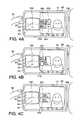
- FIGS. 4A to 4Cillustrate a variation of the imaging apparatus according to the present invention.
- FIG. 1Described with reference to a block diagram of FIG. 1 is an imaging apparatus, a preferred embodiment of electronic apparatus according to the present invention.
- FIG. 1light from a target object (not shown) is captured by lenses 210 and 230 of an optical unit 2 .
- the optical unit 2is equipped with an aperture 220 between the lenses 210 and 230 .
- the optical unit 2is, generally, equipped with multiple lenses.
- the lightis incident on an imaging device 5 , such as CCD, to be converted into electric pixel signals which are then supplied to an A/D converter 6 .
- the pixel signalsare converted into digital pixel signals by the A/D converter 6 and supplied to a video signal processor 7 .
- the video signal processor 7On receiving the pixel signals, the video signal processor 7 generates video signals, such as RGB signals, based on the pixel signals, with specific signal processing. The video signals that have been applied the specific signal processing are then supplied to a D/A converter 8 and a human face detector 9 .
- the D/A converter 8converts the video signals into analog video signals and supplies them to an OSD (On Screen Display) superimposer 11 .
- OSDOn Screen Display
- the human face detector 9detects a skin color portion in an image carried by the video signals and also detects one or more human faces contained in the image which can be done with a known pattern recognition technique. Then, the detector 9 supplies face detection information to a controller 1 .
- the controller 1which may be configured by a single or a plural number of microprocessors, includes a display controller 101 and an input processor 102 .
- a touch-panel sensor 13Connected to the input processor 102 is a touch-panel sensor 13 which may be a capacitive touch-panel sensor. When there is a user input, the touch-panel sensor 13 outputs operational information carried by the user input to the input processor 102 that applies a specific process to the operational information, as described later.
- the display controller 101controls an OSD generator 10 in accordance with the operational information processed by the input processor 102 .
- the OSD generator 10generates an OSD signal under control by the display controller 101 and supplies the OSD signal to the OSD superimposer 11 .
- the OSD superimposer 11superimposes the OSD signal on the video signals supplied from the D/A converter 8 .
- the video signals superimposed with the OSD signalare then displayed on a monitor screen 12 .
- the controller 1outputs control signals for driving a motor 3 to a motor driver 4 in accordance with the face detection information and/or the operational information supplied from the human face detector 9 and the touch-panel sensor 13 , respectively.
- the motor driver 4drives the motor 3 to shift the lenses 210 and 230 and/or adjust the aperture 220 of the optical unit 2 so that the optical unit 2 can make focusing, zooming and exposure adjustments.
- the optical unit 2 , the motor 3 and the motor driver 4constitute a zooming functional component.
- the embodimentemploys such an optical zooming functional component
- the inventioncan employ an electrical or opto-electrical zooming functional component.
- the imaging apparatusan embodiment of electronic apparatus according to the present invention, will further be described with reference to FIG. 1 and also FIGS. 2A and 2B .
- FIGS. 2A and 2BShown in FIGS. 2A and 2B are a hinged monitor 60 and a housing 100 of the imaging apparatus.
- monitor screen 12Provided on the monitor 60 are the monitor screen 12 and the touch-panel sensor 13 in the vicinity of the monitor screen 12 .
- the components other than the monitor screen 12 and the touch-panel sensor 13are installed in the housing 100 .
- the touch-panel sensor 13has four touching zones 21 to 24 , as indicated by double-dashed dotted lines, corresponding to variable resisters 131 to 134 , respectively, shown in FIG. 1 .
- the corresponding variable resister among the resisters 131 to 134varies its resistance due to change in electric charges stored in a capacitor (not shown) to vary a voltage developed thereacross.
- the input processor 102detects the change in voltage occurred across any of the variable resisters 131 to 134 to determine which of the zones 21 to 24 is touched by the user with the finger 50 .
- the monitor screen 12displays an image 70 (a human) of the target object and also OSD guide images 201 to 204 along the touching zones 21 to 24 , respectively.
- the touching zones 21 to 24are allocated with functions of the imaging apparatus (an embodiment of electronic apparatus of the present invention).
- the guide images 201 to 204indicate those functions allocated to the touching zones 21 to 24 , respectively, with words (such as shown in FIG. 2A ) meaning the functions, which may optionally be icons.
- the function allocated to a touching zone 25 that includes the touching zones 21 and 22is a zooming function. Moreover, allocated to the touching zones 21 and 22 are sub-functions of the zooming function, telephoto and wide-angle zooming functions, respectively. Allocated to the touching zones 23 and 24 are a human-face detecting function and an automatic exposure (AE) function, respectively.
- AEautomatic exposure
- the number of touching zones on the touch-panel sensor 13 and the types of function to be allocated to the touching zonesdepend on what electronic apparatus is employed within the scope of the present invention.
- the usertouches the touching zone 21 (telephoto) with his or her finger 50 at first.
- the touchcauses the change in voltage developed across the variable resister 131 that corresponds to the touching zone 21 .
- the input processor 102 of the controller 1detects the change in voltage to determine that the zone 21 is touched by the finger 50 .
- the controller 1sends a control signal for the telephoto zooming function to the motor driver 4 .
- the motor driver 4drives the motor 3 to shift the lenses 210 and 230 to vary the zoom magnification by specific times to the telephoto side.
- the controller 1continuously outputs the control signal for the telephoto zooming function as long as the zone 21 is being touched by the finger 50 , which makes the zoom magnification larger towards the maximum magnification at a specific speed.
- the usertouches the zone 22 (wide angle) with his or her finger 50 at first.
- the touchcauses the change in voltage developed across the variable resister 132 that corresponds to the zone 22 .
- the input processor 102 of the controller 1detects the change in voltage to determine that the zone 22 is touched by the finger 50 .
- the controller 1sends a control signal for the wide-angle zooming function to the motor driver 4 .
- the motor driver 4drives the motor 3 to shift the lenses 210 and 230 to vary the zoom magnification by specific times to the wide-angle side.
- the controller 1continuously outputs the control signal for the wide-angle zooming function as long as the zone 22 is being touched by the finger 50 , which makes the zoom magnification smaller towards the minimum magnification at a specific speed.
- the usertouches the zone 23 (human-face detection) with his or her finger 50 at first.
- the touchcauses the change in voltage developed across the variable resister 133 that corresponds to the zone 23 .
- the input processor 102 of the controller 1detects the change in voltage to determine that the zone 23 is touched by the finger 50 .
- the controller 1commands the human-face detector 9 to start the human-face detecting function.
- the human face detector 9detects a skin color portion in an image carried by the video signals sent from the video signal processor 7 and also detects the face of the human 70 . Then, the detector 9 supplies the face detection information to the controller 1 .
- the controller 1sends a control signal for focusing on the detected human face to the motor driver 4 .
- the motor driver 4drives the motor 3 to shift the lenses 210 and 230 to focus on the detected human face.
- the controller 1commands the human-face detector 9 to halt the human-face detecting function.
- the usertouches the zone 24 (AE) with his or her finger 50 at first.
- the touchcauses the change in voltage developed across the variable resister 134 that corresponds to the zone 24 .
- the input processor 102 of the controller 1detects the change in voltage to determine that the zone 24 is touched by the finger 50 .
- the controller 1sends a control signal to the motor driver 4 to adjust the aperture 220 of the optical unit 2 for exposure adjustments in accordance with the environments of the target object.
- the motor driver 4drives the motor 3 to adjust the aperture 220 for exposure adjustments.
- FIG. 3Described next with reference to FIG. 2A and a flowchart shown in FIG. 3 is an operation of the imaging apparatus ( FIG. 1 ), the embodiment of electronic apparatus according to the present invention, in the case where a user intentionally or unintentionally touches the touch-panel sensor 13 .
- the input processor 102 of the controller 1starts a touch-sensor input detection process in step S 301 .
- the input processor 102determines whether any of the touching zones 23 , 24 and 25 of the touch-panel sensor 13 is touched by the user with his or her finger 50 in step S 302 . If any of the zones 23 to 25 is not touched by the finger 50 (NO in step S 302 ), the input processor 102 continues the input detection process. On the contrary, if it is determined that one of the zones 23 to 25 is touched by the finger 50 at first, or there is a first touch input (YES in step S 302 ), the process goes to step S 303 .
- step S 303the input processor 102 stores zone data indicating the touched zone 23 , 24 or 25 in a memory (not shown) that may be installed in the controller 1 or another component of the imaging apparatus.
- the memoryis updated when it has already stored zone data.
- step S 303the controller 1 controls the operation of the imaging apparatus in accordance with the function assigned to the touched zone, as described below.
- the controller 1When the zone 21 in the zone 25 is determined as being touched by the finger 50 , the controller 1 performs a control procedure to change the zoom magnification to the telephoto side. On the contrary, when the zone 22 in the zone 25 is determined as being touched by the finger 50 , the controller 1 performs a control procedure to change the zoom magnification to the wide-angle side.
- the controller 1starts the human-face detection. Contrary to this, if it is the zone 23 that is determined as being touched by the finger 50 and if the human-face detection function is on at present, the controller 1 halts the human-face detection.
- the controller 1starts the automatic exposure adjustments. Contrary to this, if it is the zone 24 that is determined as being touched by the finger 50 and if the automatic exposure adjustments function is on at present, the controller 1 halts the human-face detection.
- step S 304the input processor 102 determines whether the user has released his or her finger 50 from the touch-panel sensor 13 .
- the processreturns to step S 302 if it is determined that the user has released his or her finger 50 from the touch-panel sensor 13 (YES in Step S 304 ).
- the processmoves to step S 305 if it is determined that the user has not released his or her finger 50 from the touch-panel sensor 13 (NO in Step S 304 ).
- step S 305the input processor 102 determines whether the user has shifted his or her finger 50 from the particular zone that was touched by the finger 50 at first (the first touch input) to another zone (a second touch input) on the touch-panel sensor 13 , without releasing the finger 50 from the touch-panel sensor 13 .
- the processreturns to step S 304 if it is determined that the user has not shifted his or her finger 50 from the particular zone of the touch-panel sensor 13 (NO in Step S 305 ).
- the processmoves to step S 306 if it is determined that the user has shifted his or her finger 50 from the particular zone of the touch-panel sensor 13 (YES in Step S 305 ).
- step S 306the input processor 102 accesses the zone data in the memory to determine which of the zones 21 to 24 of the touch-panel sensor 13 was touched by the user with his or her finger 50 at first.
- step S 307if it is the zone 21 or 22 that was touched by the finger 50 at first.
- step S 309if it is the zone 23 or 24 that was touched by the finger 50 at first.
- step S 309the input processor 102 replaces the operational information input through the touch-panel sensor 13 from the information corresponding to the zone to which the user has shifted his or her finger 50 to the information corresponding to the zone 23 or 24 the user touched his or her finger 50 at first. Then, the controller 1 controls the operation of the imaging apparatus in accordance with the operational information corresponding to the zone 23 or 24 even if the user has shifted his or her finger 50 to another zone, or the controller 1 controls the operation of the imaging apparatus so that the imaging apparatus does not operate in accordance with the operational information corresponding to the zone to which the user has shifted his or her finger 50 . The process then returns to step S 304 .
- step S 307that follows step S 306 , when it is determined that the zone 21 or 22 was touched by the user with his or her finger 50 at first, the input processor 102 determines from which zone to another on the touch panel 13 the user has shifted his or her finger 50 .
- step S 303the controller 1 controls the operation of the imaging apparatus in accordance with the zone 21 or 22 the user touches at present.
- step S 308the input processor 102 replaces the operational information input through the touch-panel sensor 13 from the information corresponding to the zone to which the user has shifted his or her finger 50 to the information corresponding to the zone 21 or 22 the user touched with his or her finger 50 at first.
- the controller 1controls the operation of the imaging apparatus in accordance with the operational information corresponding to the zone 21 or 22 the user touched with his or her finger 50 at first, or the controller 1 controls the operation of the imaging apparatus so that the imaging apparatus continuously operates in accordance with the zone the user touched with his or her finger 50 at first.
- the processreturns to step S 304 .
- the finger shift from the touching zone 21 or 22 to another zone in step S 307includes the shift, such as: from the zone 22 to the zone 23 ; from the zone 21 to the zone 22 via the zone 23 ; from the zone 22 to the zone 23 , then to the zone 24 ; and from the zone 22 to the zone 24 , then to the zone 23 .
- the imaging apparatuscontinuously performs the zooming function as long as the user is touching the touch-panel sensor 13 even if he or she shifts his or her finger 50 from the zone 21 or 22 to the zone 23 or 24 that is not related to the zooming function.
- the imaging apparatusoperates in accordance with the operational information input from the zone 22 (or 21 ) touched by the user at present, not the zone 21 (or 22 ) touched at first.
- the display controller 101 of the controller 1may erase the OSD guide images 203 and 204 from the touch-panel sensor 13 , as shown in FIG. 2B , in step S 303 .
- FIGS. 4A to 4CDescribed further with respect to FIGS. 4A to 4C is a variation of the imaging apparatus, the embodiment of electronic apparatus of the present invention.
- the variation of the imaging apparatusis equipped with a touch-panel sensor 130 with the touching zones 21 to 24 the same as those shown in FIG. 2A , but arranged in a 2 ⁇ 2 matrix.
- Displayed on the monitor screen 12are the OSD guide images 201 to 204 , the same as those shown in FIG. 2A , but arranged in a 2 ⁇ 2 matrix, matched with the arrangements of the touching zones 21 to 24 .
- the circuit configuration and the operations and functions related to the touching zones 21 to 24 on the touch-panel sensor 130 in the variationare the same as those of the embodiment described with respect to FIGS. 1 to 3 .
- the display controller 101 of the controller 1may display wide OSD guide images 221 and 222 , such as shown in FIG. 4C , instead of the guide images 201 and 202 shown in FIG. 4A , while erasing the guide images 203 and 204 .
- a transparent touch-panel sensormay be provided on the monitor screen 12 in FIGS. 2A and 4A .
- the touch-panel sensormay be touched by a tool, such as a pen, instead of a finger.
- the components of the imaging apparatus shown in FIG. 1may be separately controlled by several controllers instead of the single controller 1 .
- the present inventionprovides an electronic apparatus equipped with a touch sensor and a method of operating an electronic apparatus through a touch sensor, preventing misoperation of the electronic apparatus even if a user unintentionally shifts his or her finger from a touched zone to another zone on a touch panel of the touch sensor while he or she is intentionally touching the former zone to operate the electronic apparatus.
Landscapes
- Engineering & Computer Science (AREA)
- General Engineering & Computer Science (AREA)
- Theoretical Computer Science (AREA)
- Human Computer Interaction (AREA)
- Physics & Mathematics (AREA)
- General Physics & Mathematics (AREA)
- Multimedia (AREA)
- Signal Processing (AREA)
- Studio Devices (AREA)
- User Interface Of Digital Computer (AREA)
- Position Input By Displaying (AREA)
Abstract
Description
Claims (12)
Priority Applications (7)
| Application Number | Priority Date | Filing Date | Title |
|---|---|---|---|
| US13/668,347US8570425B2 (en) | 2009-01-15 | 2012-11-05 | Electronic apparatus and method of operating electronic apparatus through touch sensor |
| US13/668,362US20130057590A1 (en) | 2009-01-15 | 2012-11-05 | Electronic apparatus and method of operating electronic apparatus through touch sensor |
| US13/683,609US20130076685A1 (en) | 2009-01-15 | 2012-11-21 | Electronic apparatus and method of operating electronic apparatus through touch sensor |
| US13/683,380US8687103B2 (en) | 2009-01-15 | 2012-11-21 | Electronic apparatus and method of operating electronic apparatus through touch sensor |
| US14/179,166US9507510B2 (en) | 2009-01-15 | 2014-02-12 | Electronic apparatus and method of operating electronic apparatus through touch sensor |
| US14/179,616US9524096B2 (en) | 2009-01-15 | 2014-02-13 | Electronic apparatus and method of operating electronic apparatus through touch sensor |
| US15/352,492US9760208B2 (en) | 2009-01-15 | 2016-11-15 | Electronic apparatus and method of operating electronic apparatus through touch sensor |
Applications Claiming Priority (3)
| Application Number | Priority Date | Filing Date | Title |
|---|---|---|---|
| JP2009-006455 | 2009-01-15 | ||
| JP2009006455AJP5200948B2 (en) | 2009-01-15 | 2009-01-15 | Electronic device, operation control method, and program |
| JPJP2009-006455 | 2009-01-15 |
Related Child Applications (2)
| Application Number | Title | Priority Date | Filing Date |
|---|---|---|---|
| US13/668,347ContinuationUS8570425B2 (en) | 2009-01-15 | 2012-11-05 | Electronic apparatus and method of operating electronic apparatus through touch sensor |
| US13/668,362ContinuationUS20130057590A1 (en) | 2009-01-15 | 2012-11-05 | Electronic apparatus and method of operating electronic apparatus through touch sensor |
Publications (2)
| Publication Number | Publication Date |
|---|---|
| US20100177218A1 US20100177218A1 (en) | 2010-07-15 |
| US8339499B2true US8339499B2 (en) | 2012-12-25 |
Family
ID=42318790
Family Applications (8)
| Application Number | Title | Priority Date | Filing Date |
|---|---|---|---|
| US12/655,978Active2030-12-28US8339499B2 (en) | 2009-01-15 | 2010-01-12 | Electronic apparatus and method of operating electronic apparatus through touch sensor |
| US13/668,362AbandonedUS20130057590A1 (en) | 2009-01-15 | 2012-11-05 | Electronic apparatus and method of operating electronic apparatus through touch sensor |
| US13/668,347ActiveUS8570425B2 (en) | 2009-01-15 | 2012-11-05 | Electronic apparatus and method of operating electronic apparatus through touch sensor |
| US13/683,609AbandonedUS20130076685A1 (en) | 2009-01-15 | 2012-11-21 | Electronic apparatus and method of operating electronic apparatus through touch sensor |
| US13/683,380ActiveUS8687103B2 (en) | 2009-01-15 | 2012-11-21 | Electronic apparatus and method of operating electronic apparatus through touch sensor |
| US14/179,166Active2030-09-18US9507510B2 (en) | 2009-01-15 | 2014-02-12 | Electronic apparatus and method of operating electronic apparatus through touch sensor |
| US14/179,616Active2030-09-18US9524096B2 (en) | 2009-01-15 | 2014-02-13 | Electronic apparatus and method of operating electronic apparatus through touch sensor |
| US15/352,492ActiveUS9760208B2 (en) | 2009-01-15 | 2016-11-15 | Electronic apparatus and method of operating electronic apparatus through touch sensor |
Family Applications After (7)
| Application Number | Title | Priority Date | Filing Date |
|---|---|---|---|
| US13/668,362AbandonedUS20130057590A1 (en) | 2009-01-15 | 2012-11-05 | Electronic apparatus and method of operating electronic apparatus through touch sensor |
| US13/668,347ActiveUS8570425B2 (en) | 2009-01-15 | 2012-11-05 | Electronic apparatus and method of operating electronic apparatus through touch sensor |
| US13/683,609AbandonedUS20130076685A1 (en) | 2009-01-15 | 2012-11-21 | Electronic apparatus and method of operating electronic apparatus through touch sensor |
| US13/683,380ActiveUS8687103B2 (en) | 2009-01-15 | 2012-11-21 | Electronic apparatus and method of operating electronic apparatus through touch sensor |
| US14/179,166Active2030-09-18US9507510B2 (en) | 2009-01-15 | 2014-02-12 | Electronic apparatus and method of operating electronic apparatus through touch sensor |
| US14/179,616Active2030-09-18US9524096B2 (en) | 2009-01-15 | 2014-02-13 | Electronic apparatus and method of operating electronic apparatus through touch sensor |
| US15/352,492ActiveUS9760208B2 (en) | 2009-01-15 | 2016-11-15 | Electronic apparatus and method of operating electronic apparatus through touch sensor |
Country Status (2)
| Country | Link |
|---|---|
| US (8) | US8339499B2 (en) |
| JP (1) | JP5200948B2 (en) |
Cited By (12)
| Publication number | Priority date | Publication date | Assignee | Title |
|---|---|---|---|---|
| US20120134642A1 (en)* | 2010-11-29 | 2012-05-31 | Canon Kabushiki Kaisha | Image pickup apparatus that displays images in parallel on display unit having touch panel function and other display unit, control method therefor, and storage medium |
| US20120281117A1 (en)* | 2007-06-04 | 2012-11-08 | Sony Corporation | Information display apparatus, image taking apparatus, and method and computer program for controlling displaying information |
| USD682294S1 (en)* | 2010-12-16 | 2013-05-14 | Cisco Technology, Inc. | Display screen with graphical user interface |
| USD682854S1 (en) | 2010-12-16 | 2013-05-21 | Cisco Technology, Inc. | Display screen for graphical user interface |
| US8472415B2 (en) | 2006-03-06 | 2013-06-25 | Cisco Technology, Inc. | Performance optimization with integrated mobility and MPLS |
| US8542264B2 (en) | 2010-11-18 | 2013-09-24 | Cisco Technology, Inc. | System and method for managing optics in a video environment |
| US8797377B2 (en) | 2008-02-14 | 2014-08-05 | Cisco Technology, Inc. | Method and system for videoconference configuration |
| US8896655B2 (en) | 2010-08-31 | 2014-11-25 | Cisco Technology, Inc. | System and method for providing depth adaptive video conferencing |
| US9082297B2 (en) | 2009-08-11 | 2015-07-14 | Cisco Technology, Inc. | System and method for verifying parameters in an audiovisual environment |
| US9111138B2 (en) | 2010-11-30 | 2015-08-18 | Cisco Technology, Inc. | System and method for gesture interface control |
| CN107137100A (en)* | 2017-05-31 | 2017-09-08 | 上海联影医疗科技有限公司 | X-ray imaging equipment and its control method |
| CN107157501A (en)* | 2017-05-31 | 2017-09-15 | 上海联影医疗科技有限公司 | X-ray imaging equipment and its control method |
Families Citing this family (23)
| Publication number | Priority date | Publication date | Assignee | Title |
|---|---|---|---|---|
| JP5200948B2 (en) | 2009-01-15 | 2013-06-05 | 株式会社Jvcケンウッド | Electronic device, operation control method, and program |
| JP5306266B2 (en)* | 2010-03-15 | 2013-10-02 | キヤノン株式会社 | Imaging apparatus and control method thereof |
| TW201214237A (en)* | 2010-09-16 | 2012-04-01 | Asustek Comp Inc | Touch display device and control method thereof |
| JP2012128668A (en)* | 2010-12-15 | 2012-07-05 | Nikon Corp | Electronic device |
| JP2012145867A (en)* | 2011-01-14 | 2012-08-02 | Nikon Corp | Electronic equipment |
| JP2012215632A (en)* | 2011-03-31 | 2012-11-08 | Fujifilm Corp | Lens device and operation control method thereof |
| JP5716503B2 (en)* | 2011-04-06 | 2015-05-13 | ソニー株式会社 | Information processing apparatus, information processing method, and computer program |
| US9910559B2 (en) | 2011-04-15 | 2018-03-06 | Sharp Kabushiki Kaisha | Menu screen display control method and display control device for exchanging icons of a menu based on user instruction |
| JP5275440B2 (en)* | 2011-04-15 | 2013-08-28 | シャープ株式会社 | Numeric input device, television receiver, numeric input method, program, and recording medium |
| JP6115470B2 (en)* | 2011-09-27 | 2017-04-19 | 日本電気株式会社 | Portable electronic device, touch operation processing method and program |
| JP5808705B2 (en)* | 2012-03-29 | 2015-11-10 | シャープ株式会社 | Information input device |
| KR20130112626A (en)* | 2012-04-04 | 2013-10-14 | 삼성전자주식회사 | Operation mode controlling method of media equipment, apparatus thereof, and medium storing program source thereof |
| JP5995607B2 (en)* | 2012-08-22 | 2016-09-21 | キヤノン株式会社 | Electronic device, program and recording medium |
| TWI493532B (en)* | 2013-04-02 | 2015-07-21 | Mstar Semiconductor Inc | Display controlling device and display controlling method |
| EP3386183A1 (en)* | 2013-08-30 | 2018-10-10 | Nikon Corporation | Image processing device and image processing program |
| TWI590148B (en) | 2013-10-25 | 2017-07-01 | 宏碁股份有限公司 | Electronic device and touch operation method thereof |
| JP6545048B2 (en)* | 2015-09-02 | 2019-07-17 | キヤノン株式会社 | Electronic device, control method of electronic device, and program |
| JP6239077B2 (en)* | 2016-10-06 | 2017-11-29 | キヤノン株式会社 | Electronic device, control method therefor, program, and storage medium |
| CN107157500A (en)* | 2017-04-28 | 2017-09-15 | 上海联影医疗科技有限公司 | X-ray imaging equipment and its control method |
| US10925570B2 (en) | 2017-04-28 | 2021-02-23 | Shanghai United Imaging Healthcare Co., Ltd. | Systems and methods for controlling an X-ray imaging device |
| CN108388400B (en)* | 2018-01-25 | 2020-10-02 | 维沃移动通信有限公司 | An operation processing method and mobile terminal |
| JP7071234B2 (en)* | 2018-06-29 | 2022-05-18 | キヤノン株式会社 | Electronics |
| GB201908996D0 (en)* | 2018-06-29 | 2019-08-07 | Canon Kk | Electronic device, control method for electronic device, program, and computer readable medium |
Citations (10)
| Publication number | Priority date | Publication date | Assignee | Title |
|---|---|---|---|---|
| US5671014A (en)* | 1994-09-05 | 1997-09-23 | Sony Corporation | Video apparatus with image forming means responsive to touch sensitive display |
| JPH11175212A (en) | 1997-12-15 | 1999-07-02 | Hitachi Ltd | Touch operation processing method for touch panel device |
| US5923908A (en)* | 1997-10-30 | 1999-07-13 | Eastman Kodak Company | Camera with touch sensitive control |
| US6597400B2 (en)* | 2000-05-18 | 2003-07-22 | Sony Corporation | Image pickup apparatus and a method for operating same |
| US6778217B1 (en)* | 1998-12-14 | 2004-08-17 | Sony Corporation | Image-capturing device having an electronic viewfinder and external monitor with shared control |
| JP2004355606A (en) | 2003-02-14 | 2004-12-16 | Sony Corp | Information processor, information processing method, and program |
| US7088343B2 (en)* | 2001-04-30 | 2006-08-08 | Lenovo (Singapore) Pte., Ltd. | Edge touchpad input device |
| US7619677B2 (en)* | 2005-07-21 | 2009-11-17 | Fujifilm Corporation | Electronic camera adjusting size of image to fit display area |
| US7649562B2 (en)* | 2001-05-28 | 2010-01-19 | Fujifilm Corporation | Portable electronic device having an operation input section |
| US7804495B2 (en) | 2004-12-27 | 2010-09-28 | Pioneer Corporation | User interface system, user interface apparatus, and method of controlling electronic device |
Family Cites Families (5)
| Publication number | Priority date | Publication date | Assignee | Title |
|---|---|---|---|---|
| JP2004343662A (en)* | 2003-05-19 | 2004-12-02 | Sony Corp | Imaging apparatus |
| US20070024577A1 (en) | 2005-07-27 | 2007-02-01 | Mikko Nurmi | Method of controlling software functions, electronic device, and computer program product |
| JP5019939B2 (en)* | 2007-04-19 | 2012-09-05 | パナソニック株式会社 | Imaging apparatus and imaging method |
| JP2009163435A (en)* | 2007-12-28 | 2009-07-23 | Clarion Co Ltd | Information terminal, computer program, and display method |
| JP5200948B2 (en) | 2009-01-15 | 2013-06-05 | 株式会社Jvcケンウッド | Electronic device, operation control method, and program |
- 2009
- 2009-01-15JPJP2009006455Apatent/JP5200948B2/enactiveActive
- 2010
- 2010-01-12USUS12/655,978patent/US8339499B2/enactiveActive
- 2012
- 2012-11-05USUS13/668,362patent/US20130057590A1/ennot_activeAbandoned
- 2012-11-05USUS13/668,347patent/US8570425B2/enactiveActive
- 2012-11-21USUS13/683,609patent/US20130076685A1/ennot_activeAbandoned
- 2012-11-21USUS13/683,380patent/US8687103B2/enactiveActive
- 2014
- 2014-02-12USUS14/179,166patent/US9507510B2/enactiveActive
- 2014-02-13USUS14/179,616patent/US9524096B2/enactiveActive
- 2016
- 2016-11-15USUS15/352,492patent/US9760208B2/enactiveActive
Patent Citations (10)
| Publication number | Priority date | Publication date | Assignee | Title |
|---|---|---|---|---|
| US5671014A (en)* | 1994-09-05 | 1997-09-23 | Sony Corporation | Video apparatus with image forming means responsive to touch sensitive display |
| US5923908A (en)* | 1997-10-30 | 1999-07-13 | Eastman Kodak Company | Camera with touch sensitive control |
| JPH11175212A (en) | 1997-12-15 | 1999-07-02 | Hitachi Ltd | Touch operation processing method for touch panel device |
| US6778217B1 (en)* | 1998-12-14 | 2004-08-17 | Sony Corporation | Image-capturing device having an electronic viewfinder and external monitor with shared control |
| US6597400B2 (en)* | 2000-05-18 | 2003-07-22 | Sony Corporation | Image pickup apparatus and a method for operating same |
| US7088343B2 (en)* | 2001-04-30 | 2006-08-08 | Lenovo (Singapore) Pte., Ltd. | Edge touchpad input device |
| US7649562B2 (en)* | 2001-05-28 | 2010-01-19 | Fujifilm Corporation | Portable electronic device having an operation input section |
| JP2004355606A (en) | 2003-02-14 | 2004-12-16 | Sony Corp | Information processor, information processing method, and program |
| US7804495B2 (en) | 2004-12-27 | 2010-09-28 | Pioneer Corporation | User interface system, user interface apparatus, and method of controlling electronic device |
| US7619677B2 (en)* | 2005-07-21 | 2009-11-17 | Fujifilm Corporation | Electronic camera adjusting size of image to fit display area |
Non-Patent Citations (1)
| Title |
|---|
| JP Office Action mailed Oct. 23, 2012 with English Translation (JP 2009-006455). |
Cited By (15)
| Publication number | Priority date | Publication date | Assignee | Title |
|---|---|---|---|---|
| US8472415B2 (en) | 2006-03-06 | 2013-06-25 | Cisco Technology, Inc. | Performance optimization with integrated mobility and MPLS |
| US8848087B2 (en)* | 2007-06-04 | 2014-09-30 | Sony Corporation | Information display apparatus, image taking apparatus, and method and computer program for controlling displaying information |
| US20120281117A1 (en)* | 2007-06-04 | 2012-11-08 | Sony Corporation | Information display apparatus, image taking apparatus, and method and computer program for controlling displaying information |
| US9176594B2 (en) | 2007-06-04 | 2015-11-03 | Sony Corporation | Information display apparatus, image taking apparatus, and method and computer program for controlling displaying information |
| US8797377B2 (en) | 2008-02-14 | 2014-08-05 | Cisco Technology, Inc. | Method and system for videoconference configuration |
| US9082297B2 (en) | 2009-08-11 | 2015-07-14 | Cisco Technology, Inc. | System and method for verifying parameters in an audiovisual environment |
| US8896655B2 (en) | 2010-08-31 | 2014-11-25 | Cisco Technology, Inc. | System and method for providing depth adaptive video conferencing |
| US8542264B2 (en) | 2010-11-18 | 2013-09-24 | Cisco Technology, Inc. | System and method for managing optics in a video environment |
| US8730367B2 (en)* | 2010-11-29 | 2014-05-20 | Canon Kabushiki Kaisha | Image pickup apparatus that displays images in parallel on display unit having touch panel function and other display unit, control method therefor, and storage medium |
| US20120134642A1 (en)* | 2010-11-29 | 2012-05-31 | Canon Kabushiki Kaisha | Image pickup apparatus that displays images in parallel on display unit having touch panel function and other display unit, control method therefor, and storage medium |
| US9111138B2 (en) | 2010-11-30 | 2015-08-18 | Cisco Technology, Inc. | System and method for gesture interface control |
| USD682854S1 (en) | 2010-12-16 | 2013-05-21 | Cisco Technology, Inc. | Display screen for graphical user interface |
| USD682294S1 (en)* | 2010-12-16 | 2013-05-14 | Cisco Technology, Inc. | Display screen with graphical user interface |
| CN107137100A (en)* | 2017-05-31 | 2017-09-08 | 上海联影医疗科技有限公司 | X-ray imaging equipment and its control method |
| CN107157501A (en)* | 2017-05-31 | 2017-09-15 | 上海联影医疗科技有限公司 | X-ray imaging equipment and its control method |
Also Published As
| Publication number | Publication date |
|---|---|
| US20130076685A1 (en) | 2013-03-28 |
| US8687103B2 (en) | 2014-04-01 |
| US20130076962A1 (en) | 2013-03-28 |
| US20170060332A1 (en) | 2017-03-02 |
| US9524096B2 (en) | 2016-12-20 |
| US9760208B2 (en) | 2017-09-12 |
| US9507510B2 (en) | 2016-11-29 |
| US20140165009A1 (en) | 2014-06-12 |
| US8570425B2 (en) | 2013-10-29 |
| US20140165008A1 (en) | 2014-06-12 |
| JP5200948B2 (en) | 2013-06-05 |
| US20130057589A1 (en) | 2013-03-07 |
| US20100177218A1 (en) | 2010-07-15 |
| JP2010165149A (en) | 2010-07-29 |
| US20130057590A1 (en) | 2013-03-07 |
Similar Documents
| Publication | Publication Date | Title |
|---|---|---|
| US8339499B2 (en) | Electronic apparatus and method of operating electronic apparatus through touch sensor | |
| US20250068301A1 (en) | Information processing apparatus for responding to finger and hand operation inputs | |
| CN110395182B (en) | Motor vehicle with electronic rear view mirror | |
| JP5281838B2 (en) | Imaging device | |
| CN113994659B (en) | Electronic device, control method therefor, program, and storage medium | |
| CN112312008B (en) | Electronic device, control method of electronic device, and storage medium | |
| JP5223992B2 (en) | Electronic device, control method, program | |
| US20200068137A1 (en) | Digital camera | |
| CN116916152A (en) | Electronic device, control method, and storage medium | |
| US20100308894A1 (en) | Medical electronic apparatus and controlling method thereof | |
| JP5789017B2 (en) | Electronic device, control method, program | |
| JP5789018B2 (en) | Electronic device, control method, program | |
| JP5223993B2 (en) | Electronic device, control method, program | |
| JP2020005214A (en) | Imaging device | |
| JP6534311B2 (en) | Electronic device, control method, program | |
| KR101445611B1 (en) | Image pickup device and image pickup method | |
| JP2012248913A (en) | Imaging apparatus | |
| HK40018061A (en) | Digital camera | |
| HK40018061B (en) | Digital camera | |
| JP2019053494A (en) | Imaging device | |
| JP2013012256A (en) | Electronic device, control method, and program | |
| JP2013020649A (en) | Electronic device, control method, and program | |
| JP2013069346A (en) | Electronic device, control method, and program |
Legal Events
| Date | Code | Title | Description |
|---|---|---|---|
| AS | Assignment | Owner name:VICTOR COMPANY OF JAPAN, LTD., JAPAN Free format text:ASSIGNMENT OF ASSIGNORS INTEREST;ASSIGNOR:OHUCHI, TAKASHI;REEL/FRAME:023823/0530 Effective date:20090911 | |
| AS | Assignment | Owner name:JVC KENWOOD CORPORATION, JAPAN Free format text:MERGER;ASSIGNOR:VICTOR COMPANY OF JAPAN, LTD.;REEL/FRAME:027999/0714 Effective date:20111001 | |
| FEPP | Fee payment procedure | Free format text:PAYOR NUMBER ASSIGNED (ORIGINAL EVENT CODE: ASPN); ENTITY STATUS OF PATENT OWNER: LARGE ENTITY | |
| STCF | Information on status: patent grant | Free format text:PATENTED CASE | |
| AS | Assignment | Owner name:RAKUTEN, INC., JAPAN Free format text:ASSIGNMENT OF ASSIGNORS INTEREST;ASSIGNOR:JVC KENWOOD CORPORATION;REEL/FRAME:033802/0373 Effective date:20140917 | |
| AS | Assignment | Owner name:RAKUTEN, INC., JAPAN Free format text:CHANGE OF ADDRESS;ASSIGNOR:RAKUTEN, INC.;REEL/FRAME:037751/0006 Effective date:20150824 | |
| FPAY | Fee payment | Year of fee payment:4 | |
| MAFP | Maintenance fee payment | Free format text:PAYMENT OF MAINTENANCE FEE, 8TH YEAR, LARGE ENTITY (ORIGINAL EVENT CODE: M1552); ENTITY STATUS OF PATENT OWNER: LARGE ENTITY Year of fee payment:8 | |
| AS | Assignment | Owner name:RAKUTEN GROUP, INC., JAPAN Free format text:CHANGE OF NAME;ASSIGNOR:RAKUTEN, INC.;REEL/FRAME:058314/0657 Effective date:20210901 | |
| AS | Assignment | Owner name:RAKUTEN GROUP, INC., JAPAN Free format text:CORRECTIVE ASSIGNMENT TO CORRECT THE REMOVE PATENT NUMBERS 10342096;10671117; 10716375; 10716376;10795407;10795408; AND 10827591 PREVIOUSLY RECORDED AT REEL: 58314 FRAME: 657. ASSIGNOR(S) HEREBY CONFIRMS THE ASSIGNMENT;ASSIGNOR:RAKUTEN, INC.;REEL/FRAME:068066/0103 Effective date:20210901 | |
| MAFP | Maintenance fee payment | Free format text:PAYMENT OF MAINTENANCE FEE, 12TH YEAR, LARGE ENTITY (ORIGINAL EVENT CODE: M1553); ENTITY STATUS OF PATENT OWNER: LARGE ENTITY Year of fee payment:12 |