US8339246B2 - Systems, methods and apparatus for locating a lost remote control - Google Patents
Systems, methods and apparatus for locating a lost remote controlDownload PDFInfo
- Publication number
- US8339246B2 US8339246B2US12/649,628US64962809AUS8339246B2US 8339246 B2US8339246 B2US 8339246B2US 64962809 AUS64962809 AUS 64962809AUS 8339246 B2US8339246 B2US 8339246B2
- Authority
- US
- United States
- Prior art keywords
- remote control
- message
- presentation
- controlled device
- user input
- Prior art date
- Legal status (The legal status is an assumption and is not a legal conclusion. Google has not performed a legal analysis and makes no representation as to the accuracy of the status listed.)
- Active, expires
Links
Images


Classifications
- G—PHYSICS
- G08—SIGNALLING
- G08C—TRANSMISSION SYSTEMS FOR MEASURED VALUES, CONTROL OR SIMILAR SIGNALS
- G08C19/00—Electric signal transmission systems
- G08C19/16—Electric signal transmission systems in which transmission is by pulses
- G—PHYSICS
- G08—SIGNALLING
- G08B—SIGNALLING OR CALLING SYSTEMS; ORDER TELEGRAPHS; ALARM SYSTEMS
- G08B21/00—Alarms responsive to a single specified undesired or abnormal condition and not otherwise provided for
- G08B21/18—Status alarms
- G08B21/24—Reminder alarms, e.g. anti-loss alarms
- G—PHYSICS
- G08—SIGNALLING
- G08C—TRANSMISSION SYSTEMS FOR MEASURED VALUES, CONTROL OR SIMILAR SIGNALS
- G08C17/00—Arrangements for transmitting signals characterised by the use of a wireless electrical link
Definitions
- the creation of the wireless television remote controlsimplified the television viewing experience for most people, as viewers could remotely operate a television from the couch or other location away from the television.
- the wireless television remote controlcreated a new problem plaguing centuries—the lost remote control.
- Remote controlsare easily misplaced, easily hidden under furniture and other objects and can be carried into many locations within a home, making it difficult to locate a lost remote control.
- the viewermay spend a significant amount of time trying to locate a lost remote control rather than watching television, leading to a less than desirable viewing experience.
- FIG. 1illustrates an embodiment of an entertainment system.
- FIG. 2illustrates an embodiment of a remote control of the entertainment system of FIG. 1 .
- FIG. 3illustrates an embodiment of a flow chart for a querying process performed by the remote control and the entertainment device of FIG. 2 .
- FIG. 4illustrates an embodiment of an entertainment device of FIG. 1 .
- FIG. 5illustrates an embodiment of a process for locating a lost remote control.
- the various embodiments described hereingenerally provide apparatus, systems and methods for providing audible or visual indicators via a remote control for a controlled device. More particularly, the various embodiments described herein generally provide a controlled device, such as an entertainment device, that transmits a request to activate an audio indicator of the associated remote control. The controlled device also mutes the output of presentation content while the remote control activates the audio indicator such that a user may more easily hear the audio indicator of the remote control.
- a controlled devicesuch as an entertainment device
- the remote controlincludes an indicator device, such a speaker, buzzer, light emitting diode, display screen or vibration mechanism.
- a controlled device associated with the remote controlreceives user input requesting to activate the indicator device.
- the user inputmay request to activate a lost remote control locator feature of the remote control.
- the controlled devicetransmits a request to the remote control to activate the indicator device.
- the controlled devicemay decrease the volume of audio content output by the controlled device or an associated presentation device.
- a television receivermay mute the output of content to a television or may transmit a command to the television, requesting to mute the volume of the television.
- the userhas an easier time hearing the output of the indicator device and locating the lost remote control.
- FIG. 1illustrates an embodiment of an entertainment system 100 .
- the entertainment system 100presents content to a user 108 .
- the content presented to the user 108includes an audio/video stream, such as a television program, movie or other stored or recorded content and the like.
- the entertainment system 100includes an entertainment device 102 , a presentation device 104 and a remote control 106 . Each of these components is discussed in greater detail below.
- the entertainment system 100may include other devices, components or elements not illustrated for the sake of brevity.
- the entertainment device 102is operable to receive content from one or more content sources (not shown in FIG. 1 ) and to present the received content to the user 108 on the associated presentation device 104 .
- the presentation device 104is a display device (e.g., a television) configured to display content to the user 108 .
- the presentation device 104is an audio output device (e.g., stereo system).
- the entertainment device 102may receive an audio/video stream in any format (e.g., analog or digital format) and output the audio/video stream for presentation by the presentation device 104 .
- the entertainment device 102may be further configured to display menus and other information that allow a user 108 to control the output of content by the entertainment device 102 or may include buttons, a touch screen or the like that present information to the user 108 and/or solicit user input from the user 108 .
- the entertainment device 102is a set-top box (e.g., a satellite or cable television converter box), digital video recorder (DVR) or other similar device that processes and provides one or more audio and/or video output streams to the presentation device 104 for presentation to the user 108 .
- DVRdigital video recorder
- the entertainment device 102has multiple operating states, corresponding with different available functionalities. For example, a first operating state may correspond with a powered-on state, whereas a second operating state may correspond with a powered-off state. In some embodiments, a first operating state is associated with the entertainment device 102 outputting a menu navigable with the remote control 106 .
- the remote control 106may be any system or apparatus configured to remotely control the output of content by the entertainment device 102 .
- the remote control 106may communicate commands to the entertainment device 102 requesting to playback content, temporally move through content (e.g., fast-forward or reverse), adjust the volume, access electronic programming guides, menus and the like.
- the remote control 106may additionally be configured to remotely control the presentation device 104 .
- the remote control 106may communicate with the entertainment device 102 and/or the presentation device 104 through any type of wireless communication medium, such as infrared (IR) signals or radio-frequency (RF) signals.
- IRinfrared
- RFradio-frequency
- the user 108requests to activate a lost remote control feature of the entertainment device 102 .
- the user 108may press an associated button on a front panel of the entertainment device 102 .
- the user 108may navigate to an appropriate menu of the entertainment device 102 , such as using another remote control associated with the entertainment device 102 , to activate the lost remote control feature.
- the entertainment device 102may also include buttons or other user input interfaces that allow a user 108 to access a remote control locator feature.
- the entertainment device 102Responsive to the user input, the entertainment device 102 transmits a message to the remote control 106 , the message requesting the remote control 106 to activate an appropriate audible and/or visual indicator.
- the entertainment device 102also decreases the volume of the output of content associated with the entertainment device 102 responsive to the user input. For example, the entertainment device 102 may lower the volume of content outputted by the entertainment device 102 to the presentation device 104 . In at least one embodiment, the entertainment device 102 temporarily mutes the volume of content outputted to the presentation device 104 .
- the entertainment device 102may also be operable to decrease the volume of a device associated with the entertainment device 102 , such as the presentation device 104 .
- the entertainment device 102may transmit a command to the presentation device 104 requesting to mute the volume of the presentation device 104 . Responsive to the command, the presentation device 104 mutes the volume of content outputted therefrom.
- the entertainment device 102subsequently transmits a command to the presentation device 104 to increase its volume.
- the entertainment device 102may transmit a mute command to the presentation device 104 responsive to input from the user to activate a lost remote control feature and may transmit an un-mute command to the presentation device 104 after a particular periodic interval (e.g., one minute later).
- a particular periodic intervale.g., one minute later
- the remote control 106may be operable to periodically query the entertainment device 102 for data/requests, such as requests to activate the sound emitting device. This allows the remote control 106 to power down its receiver during certain periodic intervals to conserve battery power.
- the remote control 106may query the entertainment device 102 for operating status information, firmware updates, control command sets and other requests.
- the queries transmitted by the remote control 106may request general information from the entertainment device 102 .
- the remote control 106may request any information to be transmitted from the entertainment device 102 , e.g., status requests, commands, software/firmware updates and the like.
- the entertainment device 102may initiate transmission of any data ready to be transmitted to the remote control 106 .
- the entertainment device 102may transmit a status update, a firmware update and a request to activate an indicator of the remote control responsive to a particular query.
- the remote control 106may request specific information, such as an operating status of the entertainment device 102 .
- the entertainment device 102may transmit the requested information and may queue other data to be transmitted until a later time.
- the entertainment device 102may transmit requests to the remote control 106 to undertake specific actions. For example, the entertainment device 102 may request the remote control 106 to activate a sound emitting device, vibration inducing device, light emitting device or other visual indicator. It is to be appreciated that any combination of the aforementioned indicators may be activated by the remote control 106 responsive to the request from the entertainment device 102 .
- the indicatoris activated for a specified period of time (e.g., the request from the entertainment device 102 may specify the fixed period of time).
- the remote control 106may deactivate the indicator after a specified period of time in order to conserve battery power.
- the indicatormay also be activated until a specified event occurs (e.g., a button press on the remote control).
- the entertainment device 102may subsequently instruct the remote control to deactivate the indicator. For example, in response to some queries, the entertainment device 102 may request the remote control 106 to deactivate the sound emitting device or other indicator.
- a querymay be transmitted responsive to a specified event. For example, a query may be transmitted a specified period of time after the last receipt of input by the remote control 106 . In another example, the remote control 106 may transmit a query responsive to receipt of a particular type of input, e.g., a particular button press. In another example, the remote control 106 may transmit a query to the entertainment device 102 regarding whether to deactivate a sound emitting device responsive to a request by the entertainment device 102 to activate the same.
- a querymay be transmitted a specified event. For example, a query may be transmitted a specified period of time after the last receipt of input by the remote control 106 . In another example, the remote control 106 may transmit a query responsive to receipt of a particular type of input, e.g., a particular button press. In another example, the remote control 106 may transmit a query to the entertainment device 102 regarding whether to deactivate a sound emitting device responsive to a request by the entertainment device 102 to activate the same.
- the queriesmay be conducted according to a pre-determined schedule.
- the remote control 106may query the entertainment device 102 every two seconds requesting any status changes or other data to be exchanged.
- the remote control 106may determine whether to enter a low power mode state based upon the query response.
- the remote control 106may be configured to periodically enter a limited power mode state (e.g., a sleep mode state or stand-by mode state) to conserve battery power. More particularly, components of the remote control 106 , such as processors, user input circuitry, transceivers, backlighting, display screens and the like may be commanded to enter a limited power mode state when the functionality of the components is not needed by the entertainment system 100 . For example, the remote control 106 may enter a sleep mode state when the entertainment device 102 is powered off. Particular components of the remote control may also enter a limited power mode state if the entertainment device 102 is in an operational state that does not involve soliciting input from the user 108 via the remote control 106 .
- a limited power mode statee.g., a sleep mode state or stand-by mode state
- components of the remote control 106such as processors, user input circuitry, transceivers, backlighting, display screens and the like may be commanded to enter a limited power mode state when the functionality of the components is not
- the remote control 106queries the entertainment device 102 to determine whether to enter a limited power mode state while operating in an active mode state. For example, the remote control 106 may operate in an active mode state that includes utilizing a touch pad input device in an active mode state to solicit user input for controlling a menu outputted by the entertainment device 102 for display by the presentation device 104 . While the touch pad input device operates in the active mode state, the remote control 106 may periodically query the entertainment device 102 to determine whether the entertainment device 102 is still operating in a state that utilizes the touch pad input device. If the operating state of the entertainment device 102 does not need to utilize the touch pad input device (e.g., the entertainment device 102 is no longer outputting a menu), then the remote control 106 may command the touch pad input device to enter a limited power mode state.
- the remote control 106may command the touch pad input device to enter a limited power mode state.
- the remote control 106may operate in an active mode state, and may query the entertainment device 102 and receive a response indicating that the entertainment device 102 has been powered off. For example, the user 108 may have powered off the entertainment device 102 using a front console of the entertainment device 102 .
- the components of the remote control 106may enter a limited power mode state, periodically waking to query the entertainment device 102 for operational mode changes (e.g., powering on the entertainment device 102 ). If an operational mode change is detected by the remote control 106 , then appropriate components of the remote control 106 may be commanded to enter an active mode state corresponding with the operational state of the entertainment device 102 .
- FIG. 2illustrates an embodiment of a remote control of the entertainment system 100 of FIG. 1 .
- the remote control 106 Aincludes a wireless transceiver 202 , user input circuitry 204 , control logic 206 and a sound emitting device 208 . Each of these components is discussed in greater detail below.
- the remote control 106 Amay contain other devices, such as display screens, backlighting and non-volatile memory, not mentioned herein for the sake of brevity.
- the user input circuitry 204is operable to receive and/or process user input from the user 108 (see FIG. 1 ).
- the user input circuitry 204is a keypad including a set of buttons.
- the user 108may utilize the keypad to input channel numbers, control the volume of the entertainment device 102 , navigate menus, manipulate the output of content by the entertainment device 102 and/or control other functions of the entertainment device 102 and/or the presentation device 104 .
- the wireless transceiver 202is operable to bi-directionally communicate with the entertainment device 102 and/or the presentation device 104 .
- the wireless transceiver 202may utilize any type of wireless protocol and wireless communication medium, including RF and/or IR key codes or commands, to communicate with the entertainment device 102 (see FIG. 1 ) and/or the presentation device 104 .
- the wireless transceiver 202is operable to transmit a key code and/or command message corresponding with user input to the entertainment device 102 .
- the wireless transceiver 202is also operable to exchange other data with the entertainment device 102 , such as operational status queries and responses.
- the wireless transceiver 202may transmit queries to the entertainment device 102 responsive to a pre-defined schedule.
- the remote control 106 Amay also receive IR database key codes, RF database key codes or firmware updates from the entertainment device 102 responsive to the queries.
- the wireless transceiver 202receives data from the entertainment device 102 requesting to activate the sound emitting device 208 . Data received from the entertainment device 102 by the wireless transceiver 202 is transferred to the control logic 206 for processing.
- the control logic 206is operable to control the operation of the remote control 106 A.
- the control logic 206may be a single processing device or a plurality of processing devices that cooperatively operate to control the operation of the remote control 106 .
- the operation of the remote control 106may be controlled by instructions executable by the control logic 206 .
- Some examples of instructionsare software, program code, and firmware.
- the control logic 206is operable to generate control commands for the entertainment device 102 responsive to the input provided to the user input circuitry 204 by the user 108 (see FIG. 1 ).
- the control commandsmay be in the form of key codes or other commands that are compatible with the entertainment device 102 .
- the control commandsmay also allow for the control of the presentation device 104 .
- the control logic 206is also operable to process data received from the entertainment device 102 and/or the display device 104 .
- the control logic 206may process data received from the entertainment device 102 and activate the sound emitting device 208 to output sounds, such as tones, music, speech and the like.
- the sound emitting device 208may comprise a speaker, a buzzer or other type of device operable to emit sounds perceptible to the user 108 (see FIG. 1 ).
- the sound emitting device 208may include appropriate circuitry for outputting different sounds, tones, frequencies and the like.
- the sound emitting device 208may include voice synthesizer circuitry for outputting synthetic speech data.
- other types of indicator devicessuch as visual indicators (e.g., display screens) or physical indicators (e.g., vibration mechanisms) may be utilized as an alternative or supplement to the sound emitting device 208 .
- a request from the entertainment device 102may specify parameters for activation of the sound emitting device 208 .
- the requestmay specify the tone, frequency, duration, sound or speech (if appropriate) and the like.
- the requestmay specify the purpose of the indicator and the control logic 206 may process the request to determine parameters for activating the sound emitting device 208 .
- a request from the entertainment device 102 to activate the sound emitting device 208may be responsive to input from the user 108 requesting to locate the remote control 106 A.
- the control logic 206may process the request to determine which tone and frequency to output based on the information in the request.
- the control logic 206is operable to activate the sound emitting device 208 for a specified period of time, e.g., one minute.
- the user 108may deactivate the sound emitting device 208 by providing input to either the remote control 106 A, via the user input circuitry 204 , or via the entertainment device 102 or presentation device 104 .
- the user 108may press one or more buttons of the user input circuitry 204 .
- the control logic 206then processes the user input and responsively deactivates the sound emitting device 208 . If the user 108 provides input via a front panel of the entertainment device 102 or via another remote control for the entertainment device 102 , then the entertainment device 102 transmits a request to the remote control 106 A to deactivate the sound emitting device 208 .
- the control logic 206processes the request and deactivates the sound emitting device 208 .
- the request to deactivate the sound emitting device 208is transmitted to the remote control 106 A responsive to a query from the wireless transceiver 202 .
- the control logic 206may also be operable to deactivate the sound emitting device 208 after a specified period of time (e.g., to conserve battery power).
- the remote control 106 Amay include other types of indicators, such as light emitting devices or other display devices.
- the remote control 106 Amay include LEDs or other lights which can be flashed to indicate information to the user 108 .
- the user input circuitry 204includes buttons with integrated LEDs. Thus, the buttons of the user input circuitry may be flashed to indicate information to the user 108 .
- the visual indicatorsmay be activated by the control logic 206 in association with the sound emitting device 208 or independently, depending on desired design criteria.
- FIG. 3illustrates an embodiment of a flow chart for a querying process performed by the remote control 106 A and the entertainment device 102 of FIG. 2 .
- the operation of FIG. 3will be described in reference to the entertainment system 100 described in FIGS. 1 and 2 .
- the process of FIG. 3may include other operations not illustrated for the sake of brevity.
- the remote control 106 Aplaces the wireless transceiver 202 in a transmit mode (operation 302 A).
- the entertainment device 102 transceiveroperates in a receive mode, ready to receive messages and commands from the wireless transceiver 202 of the remote control 106 A (operation 302 B).
- the wireless transceiver 202transmits a query message to the entertainment device 102 .
- the wireless transceiver 202 of the remote control 106 Aswitches to a receive mode, ready to receive a response to the query from the entertainment device (operation 306 A).
- the entertainment device 102receives the query message (operation 304 B) and switches the transceiver of the entertainment device to a transmit mode to respond to the query (operation 306 B).
- the entertainment device 102identifies any information to be transmitted to the remote control 106 A and transmits a response message to the remote control 106 A (operation 308 B). For example, the entertainment device 102 may identify firmware updates, power state changes, configuration changes, operational mode changes and requests to activate the sound emitting device 208 of the remote control 106 A and transmit such information in the response. In at least one scenario, the entertainment device 102 may transmit a message to the wireless transceiver 202 indicating that there is no information to convey. After transmitting the message, the wireless transceiver of the entertainment device 102 switches to a receive mode (operation 310 B), ready to receive another query from the remote control 106 A and/or a command from the remote control 106 A (operation 312 B).
- a receive modeoperation 310 B
- the wireless transceiver 202 of the remote control 106 Areceives the response message from the remote control 106 A and transmits the message to the control logic 206 for further processing (operation 308 A).
- the wireless transceiver 202then turns off or otherwise enters a low power mode state until the remote control 106 A is ready to transmit another query message (operation 310 A).
- the control logic 206then processes the response message as appropriate (operation 312 A). For example, the control logic 206 may command the sound emitting device 208 to emit a sound responsive to the message from the entertainment device 102 .
- the remote control 106 Adoes not operate the wireless transceiver 202 in an active mode at all times, the battery life of the remote control 106 A is increased. Operating the wireless transceiver 202 in an active mode at all times is power intensive and significantly shortens the life of the battery powering the remote control 106 A. However, as described above, the remote control 106 A may bi-directionally communicate with the entertainment device 102 and receive information as appropriate, such as requests to activate the sound emitting device 208 , without activating the wireless transceiver 202 to listen for such requests at unnecessary times.
- the remote control 106 Adetermines when to access such requests and other data from the entertainment device 102 , and activates the wireless transceiver 202 as appropriate to exchange such data, conserving battery power and increasing the battery life for the battery of the remote control 106 A.
- the remote control 106 Amay exchange data with the entertainment device 102 according to a default timing period or may exchange data with the entertainment device 102 according to a schedule adjusted based on commands from the entertainment device 102 .
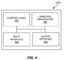
- FIG. 4illustrates an embodiment of an entertainment device 102 A of FIG. 1 . More particularly, FIG. 4 illustrates an entertainment device 102 A embodied as a television receiver (e.g., a set-top box). However, it is to be appreciated that the entertainment device 102 A may comprise any type of device that presents any type of presentation content, including DVD players, audio receivers, audio playback devices, video servers and internet connected video playback devices. FIG. 4 will be discussed in reference to the entertainment system 100 illustrated in FIG. 1 .
- the entertainment device 102 Aincludes control logic 402 , an output interface 404 , a wireless transceiver 406 and an input interface 408 . Each of these components will be discussed in greater detail below.
- the entertainment device 102 Amay include other components or devices not illustrated for the sake of brevity.
- control logic 402is operable for controlling the operation of the entertainment device 102 A.
- control logic 402refers to a single processing device or a group of inter-operational processing devices.
- the operation of the control logic 402may be controlled by instructions executable by the control logic 402 .
- Some examples of instructionsare software, program code, and firmware.
- the operation of particular functionalities of the control logic 402is controllable based on commands received from a remote control 106 (see FIG. 1 ).
- the control logic 402includes at least a first operating state and a second operating state. The operating states may be of any type as described above.
- control logic 402is operable for receiving presentation content, e.g., video content.
- the control logic 402may be operable for receiving and tuning any type of video content.
- the control logic 402may receive an over-the-air broadcast signal, an internet protocol video stream, a direct broadcast satellite signal or a cable television signal.
- the control logic 402includes a tuner for receiving video content from an external source, such as a television distribution network.
- the control logic 402may also receive or retrieve content from a storage medium, such as an optical disk, internal or external hard drive, a portable storage device (e.g., universal serial bus (USB) memory sticks) and the like.
- the control logic 402may also receive content from external servers, such as video servers, that are communicatively coupled to the entertainment device 102 A over the internet or other type of data networks.
- the output interface 404is operable to interface with the presentation device 104 (see FIG. 1 ). More particularly, the output interface 404 is operable to output information for presentation by the presentation device 104 .
- the output interface 404may be operable to output any type of presentation data to the presentation device 104 , including audio data, video data, audio/video (A/V) data, textual data, imagery or the like.
- the output interface 404may operate to perform various signal and data processing functions such as demodulation, decoding, decryption and the like on data signals received via any type of network interface, to generate an appropriate format video stream for output to the presentation device 104 (see FIG. 1 ).
- the output interface 404may comprise multiple components, such as a demodulator, an audio decoder, a video decoder, a data decoder or a graphics processor to generate the video stream.
- Commands received from the remote control 106are operable to control the output of audio and video content by the output interface 404 .
- the wireless transceiver 406may receive a key code causing the output interface 404 to manipulate the output of the video content responsive to the key code.
- the output interface 404operates to output a video stream for presentation by the presentation device 104 .
- the video stream generated by the output interface 404may include menus, electronic programming guides and the like that are navigable using commands received from the remote control 106 .
- the wireless transceiver 406is operable to wirelessly receive and/or transmit data to the remote control 106 .
- the wireless transceiver 406may communicate with the remote control 106 utilizing any type of IR and/or RF communication link.
- the wireless transceiver 406receives a key code from the remote control 106 , and responsively provides the key code to the control logic 402 .
- the wireless transceiver 406is further operable to exchange data with the remote control 106 , such as IR database code updates, firmware updates and the like.
- the wireless transceiver 406is further operable to exchange operational state queries and operational state responses with the remote control 106 .
- the remote control 106transmits an operational state query to the wireless transceiver 406 .
- the wireless transceiver 406receives the operational state response to the query from the control logic 402 and transmits the operational state response to the remote control 106 .
- the remote control 106utilizes the operational state response, as described above, to determine whether to transition to or from a limited power mode state.
- the wireless transceiver 406is also operational to transmit other data to the remote control 106 .
- the wireless transceiver 406may transmit a command, generated by the control logic 402 , requesting the remote control 106 to activate an audible, visual or physical indicator, such as a speaker, LED, vibration device or the like.
- a request to activate an indicatormay be transmitted responsive to a query from the remote control 106 .
- the control logic 402generates a request to activate an indicator
- the wireless transceiver 406 and/or control logic 402queues such request until a query is received from the remote control 106 .
- the input interface 408may comprise any type of input device, such as one or more buttons, a keypad, a touch panel or touch screen and the like for receiving input from the user 108 .
- the input interface 408includes a lost remote recovery button by which a user 108 may request to locate the remote control 106 .
- the control logic 402Responsive to input provided by the user 108 , the control logic 402 generates a request to the remote control 106 to activate an audio or visual indicator.
- the wireless transceiver 406then transmits such request to the remote control 106 during the next cycle of query/response exchanges between the entertainment device 102 A and the remote control 106 .
- the remote control 106may query the entertainment device 102 A according to a pre-determined schedule, such as five seconds between queries.
- the control logic 402may also generate requests to activate the indicator of the remote control 106 based on input from other remote controls.
- the entertainment device 102 Amay be associated with multiple remote controls, and a user may desire to locate a misplaced remote control 106 .
- the user 108may utilize another remote control or buttons of the entertainment device 102 A to navigate menus outputted by the control logic 402 to request to locate the lost remote control 106 .
- the control logic 402responsively generates a request for the remote control 106 to activate the sound emitting device.
- the control logic 402generates a request to activate the indicator of the remote control and specifies parameters for activation of the indicator. For example, the control logic 402 may specify tone, frequency, duration and the like for activation of a sound emitting device of the remote control 106 . Such parameters may be determined based on the reason for activating the indicator, user defined preferences and the like.
- the control logic 402may also generate a request to deactivate the indicator. For example, the control logic 402 may request the remote control 106 to deactivate a sound emitting device after a specified period of time or based on receipt of additional user input, via the input interface 408 or via another remote control.
- control logic 402is also operable to decrease the volume of the output of content associated with the entertainment device 102 A.
- the control logic 402commands the output interface to decrease the volume of content outputted by the output interface 404 to the presentation device 104 (see FIG. 1 ).
- the output interface 404may mute the volume of content it outputs to the presentation device 104 .
- the control logic 402may initiate a decrease of the volume of the presentation device 104 .
- the control logic 402may generate a command requesting the presentation device 104 to mute its volume.
- the wireless transceiver 404responsively outputs the mute command to the television.
- the entertainment device 102 A and the presentation device 104may also be communicatively coupled by a data bus that allows the control logic 402 to initiate transmission of a mute command to the presentation device 104 .
- the wireless transceiver 404comprises an IR blaster that transmits the command from the entertainment device 102 A to the presentation device 104 .
- FIG. 5illustrates an embodiment of a process for locating a lost remote control. It is to be appreciated that the process may be applied to remote controls for any type of controlled device. The process of FIG. 5 is not all inclusive, and may include other operations not illustrated for the sake of brevity.
- the processincludes receiving user input, at the controlled device, the user input requesting to locate a lost remote control for the controlled device (operation 502 ).
- the inputmay be received via the controlled device directly, e.g., from buttons of the controlled device.
- the inputmay also be received by the controlled device indirectly, e.g., via another remote control.
- the processfurther includes lowering a volume of the output of content associated with the controlled device responsive to the user input (operation 504 ).
- the processfurther includes transmitting a message from the controlled device to the remote control, the message requesting the remote control to activate a sound emitting device of the remote control (operation 506 ). Responsive to the command, the remote control activates the sound emitting device, allowing the user to locate the lost remote control. It is to be appreciated that operations 504 and 506 may be performed sequentially or concurrently depending on desired design criteria.
Landscapes
- Physics & Mathematics (AREA)
- General Physics & Mathematics (AREA)
- Business, Economics & Management (AREA)
- Emergency Management (AREA)
- Engineering & Computer Science (AREA)
- Computer Networks & Wireless Communication (AREA)
- Selective Calling Equipment (AREA)
Abstract
Description
Claims (20)
Priority Applications (2)
| Application Number | Priority Date | Filing Date | Title |
|---|---|---|---|
| US12/649,628US8339246B2 (en) | 2009-12-30 | 2009-12-30 | Systems, methods and apparatus for locating a lost remote control |
| US13/715,949US8633808B2 (en) | 2009-12-30 | 2012-12-14 | Systems, methods and apparatus for locating a lost remote control |
Applications Claiming Priority (1)
| Application Number | Priority Date | Filing Date | Title |
|---|---|---|---|
| US12/649,628US8339246B2 (en) | 2009-12-30 | 2009-12-30 | Systems, methods and apparatus for locating a lost remote control |
Related Child Applications (1)
| Application Number | Title | Priority Date | Filing Date |
|---|---|---|---|
| US13/715,949ContinuationUS8633808B2 (en) | 2009-12-30 | 2012-12-14 | Systems, methods and apparatus for locating a lost remote control |
Publications (2)
| Publication Number | Publication Date |
|---|---|
| US20110156862A1 US20110156862A1 (en) | 2011-06-30 |
| US8339246B2true US8339246B2 (en) | 2012-12-25 |
Family
ID=44186793
Family Applications (2)
| Application Number | Title | Priority Date | Filing Date |
|---|---|---|---|
| US12/649,628Active2031-06-24US8339246B2 (en) | 2009-12-30 | 2009-12-30 | Systems, methods and apparatus for locating a lost remote control |
| US13/715,949ActiveUS8633808B2 (en) | 2009-12-30 | 2012-12-14 | Systems, methods and apparatus for locating a lost remote control |
Family Applications After (1)
| Application Number | Title | Priority Date | Filing Date |
|---|---|---|---|
| US13/715,949ActiveUS8633808B2 (en) | 2009-12-30 | 2012-12-14 | Systems, methods and apparatus for locating a lost remote control |
Country Status (1)
| Country | Link |
|---|---|
| US (2) | US8339246B2 (en) |
Cited By (4)
| Publication number | Priority date | Publication date | Assignee | Title |
|---|---|---|---|---|
| US20100208146A1 (en)* | 2009-02-19 | 2010-08-19 | EchoStar Technologies, L.L.C. | Systems, methods and apparatus for providing an audio indicator via a remote control |
| US20120178371A1 (en)* | 2010-07-23 | 2012-07-12 | Mukesh Patel | Automatic updates to a remote control device |
| US8633808B2 (en) | 2009-12-30 | 2014-01-21 | Echostar Technologies Llc | Systems, methods and apparatus for locating a lost remote control |
| US20240265797A1 (en)* | 2023-02-07 | 2024-08-08 | Claude Hasty | TV Remote Locator |
Families Citing this family (37)
| Publication number | Priority date | Publication date | Assignee | Title |
|---|---|---|---|---|
| US9094723B2 (en)* | 2008-12-16 | 2015-07-28 | Echostar Technologies L.L.C. | Systems and methods for a remote alarm |
| US9599981B2 (en) | 2010-02-04 | 2017-03-21 | Echostar Uk Holdings Limited | Electronic appliance status notification via a home entertainment system |
| TW201201521A (en)* | 2010-06-22 | 2012-01-01 | Hon Hai Prec Ind Co Ltd | Remote control system, electronic device, remote controller and method for searching remote controller |
| US8667100B2 (en) | 2010-07-07 | 2014-03-04 | Comcast Interactive Media, Llc | Device communication, monitoring and control architecture and method |
| EP2759901B1 (en)* | 2013-01-18 | 2021-03-10 | Elation Lighting, Inc. | Light controller with locked split handle |
| US9355559B1 (en)* | 2013-05-23 | 2016-05-31 | Amazon Technologies, Inc. | Media device control profile selection |
| US20150091727A1 (en)* | 2013-10-02 | 2015-04-02 | Lawrence Lee Moses | Mobile device locator |
| US9900177B2 (en) | 2013-12-11 | 2018-02-20 | Echostar Technologies International Corporation | Maintaining up-to-date home automation models |
| US20150161452A1 (en) | 2013-12-11 | 2015-06-11 | Echostar Technologies, Llc | Home Monitoring and Control |
| US9769522B2 (en) | 2013-12-16 | 2017-09-19 | Echostar Technologies L.L.C. | Methods and systems for location specific operations |
| US9401078B2 (en)* | 2014-02-26 | 2016-07-26 | Dell Products L.P. | Systems and methods for muting visual indicators in an information handling system |
| US9723393B2 (en) | 2014-03-28 | 2017-08-01 | Echostar Technologies L.L.C. | Methods to conserve remote batteries |
| US9621959B2 (en) | 2014-08-27 | 2017-04-11 | Echostar Uk Holdings Limited | In-residence track and alert |
| US9824578B2 (en) | 2014-09-03 | 2017-11-21 | Echostar Technologies International Corporation | Home automation control using context sensitive menus |
| US9989507B2 (en) | 2014-09-25 | 2018-06-05 | Echostar Technologies International Corporation | Detection and prevention of toxic gas |
| US9511259B2 (en) | 2014-10-30 | 2016-12-06 | Echostar Uk Holdings Limited | Fitness overlay and incorporation for home automation system |
| US9983011B2 (en) | 2014-10-30 | 2018-05-29 | Echostar Technologies International Corporation | Mapping and facilitating evacuation routes in emergency situations |
| US9967614B2 (en) | 2014-12-29 | 2018-05-08 | Echostar Technologies International Corporation | Alert suspension for home automation system |
| US9729989B2 (en) | 2015-03-27 | 2017-08-08 | Echostar Technologies L.L.C. | Home automation sound detection and positioning |
| US9946857B2 (en) | 2015-05-12 | 2018-04-17 | Echostar Technologies International Corporation | Restricted access for home automation system |
| US9948477B2 (en) | 2015-05-12 | 2018-04-17 | Echostar Technologies International Corporation | Home automation weather detection |
| US9632746B2 (en)* | 2015-05-18 | 2017-04-25 | Echostar Technologies L.L.C. | Automatic muting |
| KR20160139934A (en)* | 2015-05-29 | 2016-12-07 | 삼성전자주식회사 | Remote control apparatus, method for providing vibration feedback thereof, and display system |
| US9960980B2 (en) | 2015-08-21 | 2018-05-01 | Echostar Technologies International Corporation | Location monitor and device cloning |
| US9996066B2 (en) | 2015-11-25 | 2018-06-12 | Echostar Technologies International Corporation | System and method for HVAC health monitoring using a television receiver |
| US10101717B2 (en) | 2015-12-15 | 2018-10-16 | Echostar Technologies International Corporation | Home automation data storage system and methods |
| US9798309B2 (en) | 2015-12-18 | 2017-10-24 | Echostar Technologies International Corporation | Home automation control based on individual profiling using audio sensor data |
| US10091017B2 (en) | 2015-12-30 | 2018-10-02 | Echostar Technologies International Corporation | Personalized home automation control based on individualized profiling |
| US10073428B2 (en) | 2015-12-31 | 2018-09-11 | Echostar Technologies International Corporation | Methods and systems for control of home automation activity based on user characteristics |
| US10060644B2 (en) | 2015-12-31 | 2018-08-28 | Echostar Technologies International Corporation | Methods and systems for control of home automation activity based on user preferences |
| US9628286B1 (en) | 2016-02-23 | 2017-04-18 | Echostar Technologies L.L.C. | Television receiver and home automation system and methods to associate data with nearby people |
| NL2016304B1 (en)* | 2016-02-23 | 2017-09-07 | Fugro N V | Monitoring an offshore construction. |
| US9882736B2 (en) | 2016-06-09 | 2018-01-30 | Echostar Technologies International Corporation | Remote sound generation for a home automation system |
| US10294600B2 (en) | 2016-08-05 | 2019-05-21 | Echostar Technologies International Corporation | Remote detection of washer/dryer operation/fault condition |
| US10049515B2 (en) | 2016-08-24 | 2018-08-14 | Echostar Technologies International Corporation | Trusted user identification and management for home automation systems |
| US11789125B2 (en)* | 2021-09-10 | 2023-10-17 | Li Zhijian | Position locator |
| CN113689680A (en)* | 2021-09-10 | 2021-11-23 | 泉州新汉特箱包轻工有限公司 | Location finder |
Citations (51)
| Publication number | Priority date | Publication date | Assignee | Title |
|---|---|---|---|---|
| US4067000A (en) | 1976-05-28 | 1978-01-03 | Rca Corporation | Remote control transmitter with an audible battery life indicator |
| US4231026A (en) | 1978-09-13 | 1980-10-28 | Power Conversion, Inc. | Battery discharge level detection circuit |
| US4578671A (en) | 1984-12-05 | 1986-03-25 | International Business Machines Corp. | Remote indicating low battery voltage enunciator method and apparatus |
| JPS6430848A (en) | 1987-07-27 | 1989-02-01 | Hitachi Ltd | Control method for automatic transmission |
| US5115236A (en) | 1987-11-18 | 1992-05-19 | U.S. Philips Corporation | Remote control system using a wake up signal |
| US5164652A (en) | 1989-04-21 | 1992-11-17 | Motorola, Inc. | Method and apparatus for determining battery type and modifying operating characteristics |
| US5204657A (en) | 1991-05-28 | 1993-04-20 | Impact Products Corporation | Locating device |
| US5294915A (en) | 1991-12-27 | 1994-03-15 | Owen C Randal | Means for locating a remote control device |
| US5455560A (en) | 1994-02-25 | 1995-10-03 | Owen; C. Randal | Means for locating a remote control device |
| US5506572A (en) | 1993-06-23 | 1996-04-09 | Lodgenet Entertainment Corporation | Low battery detection system |
| US5598143A (en) | 1993-12-13 | 1997-01-28 | Wentz; Jeff D. | Remote control beeper locator |
| US5638050A (en) | 1995-12-29 | 1997-06-10 | Universal Electronics, Inc. | System for locating an object |
| GB2331610A (en) | 1997-11-19 | 1999-05-26 | Lg Electronics Inc | Assigning a remote controller identification code, and power saving |
| US5926090A (en) | 1996-08-26 | 1999-07-20 | Sharper Image Corporation | Lost article detector unit with adaptive actuation signal recognition and visual and/or audible locating signal |
| US5945918A (en) | 1990-12-19 | 1999-08-31 | Mark G. McGonigal | Apparatus and method for locating a remote control unit |
| US5963010A (en) | 1996-10-31 | 1999-10-05 | Hitachi, Ltd. | Battery controller for controlling batteries of different kinds and including battery monitoring means for calculating remaining operation time and an information processing apparatus including such battery controller |
| US5990868A (en) | 1997-04-01 | 1999-11-23 | Compaq Computer Corp. | Method and apparatus for performing power conservation in a pointing device located on a wireless data entry device |
| US5999799A (en) | 1996-04-26 | 1999-12-07 | Samsung Electronics Co., Ltd. | Auto-finder and distance warning method and apparatus for a remote control input device |
| JPH11355153A (en) | 1998-06-11 | 1999-12-24 | Nec Home Electron Ltd | Remote control transmitter |
| JP2000130848A (en) | 1998-10-23 | 2000-05-12 | Noritz Corp | Water heater |
| US6191551B1 (en) | 1999-06-30 | 2001-02-20 | Research In Motion Limited | Automatic battery detection system and method for detecting a rechargeable battery with low remaining charge |
| US6373256B1 (en) | 1999-01-08 | 2002-04-16 | Fairchild Semiconductor Corporation | Programmable low battery detector |
| US20030035074A1 (en) | 2001-08-17 | 2003-02-20 | Dubil Thomas James | Remote control device having a display for displaying a television channel guide |
| US6535125B2 (en) | 2000-08-22 | 2003-03-18 | Sam W. Trivett | Remote control locator system |
| US6573832B1 (en) | 2000-11-21 | 2003-06-03 | Lyne Fugere-Ramirez | Remote control finder |
| US20030140343A1 (en) | 2002-01-18 | 2003-07-24 | General Instrument Corporation | Remote wireless device with EPG display, intercom and emulated control buttons |
| US20030149978A1 (en) | 2002-02-07 | 2003-08-07 | Bruce Plotnick | System and method for using a personal digital assistant as an electronic program guide |
| US20030159146A1 (en) | 2000-06-29 | 2003-08-21 | Deok-Woo Kim | Remote controller and broadcasting receiver having electronic program guide (epu) function and service system and method using same |
| US20040148632A1 (en) | 2003-01-23 | 2004-07-29 | Ji-Hyun Park | Remote controller and set-top-box therefor |
| US20040168187A1 (en) | 1996-10-08 | 2004-08-26 | Allen Chang | Talking remote control with display |
| US20040203554A1 (en) | 2002-04-03 | 2004-10-14 | Simon Anthony Luke | Method and system for interfacing a portable transceiver in a telematics system |
| US20050105396A1 (en) | 2003-11-17 | 2005-05-19 | Nokia Corporation | Applications and methods for providing a reminder or an alert to a digital media capture device |
| US6938101B2 (en) | 2001-01-29 | 2005-08-30 | Universal Electronics Inc. | Hand held device having a browser application |
| US20050204388A1 (en) | 1998-06-11 | 2005-09-15 | Knudson Edward B. | Series reminders and series recording from an interactive television program guide |
| US6985069B2 (en) | 2000-12-06 | 2006-01-10 | Koninklijke Philips Electronics N.V. | Remote control with status indicator |
| US20060034611A1 (en) | 2004-08-16 | 2006-02-16 | Weidong Li | Method and system for reducing power consumption of IrDA enabled handsets by turning on/off an IrDA port dynamically |
| US7009528B2 (en) | 2001-10-26 | 2006-03-07 | Koninklijke Philips Electronics N.V. | Two-way remote control system |
| US7140033B1 (en) | 2000-06-21 | 2006-11-21 | Bellsouth Intellectual Property Corporation | Methods and systems for controlling consumer electronics external devices via data delivered to a device |
| US20070018845A1 (en) | 2005-07-19 | 2007-01-25 | Sehat Sutardja | Two way remote control |
| US20070162939A1 (en) | 2006-01-12 | 2007-07-12 | Bennett James D | Parallel television based video searching |
| US20080088748A1 (en) | 2006-10-11 | 2008-04-17 | Boon Chen Lim | Voice multi-function remote control |
| US20080163049A1 (en) | 2004-10-27 | 2008-07-03 | Steven Krampf | Entertainment system with unified content selection |
| US20080278635A1 (en)* | 2007-05-08 | 2008-11-13 | Robert Hardacker | Applications for remote control devices with added functionalities |
| US20090070840A1 (en) | 2007-09-05 | 2009-03-12 | Hitachi, Ltd. | Terminal-Cooperated System, Terminal, Server and Method for Uninterrupted Reception of Contents |
| US20090243909A1 (en) | 2008-03-27 | 2009-10-01 | Echostar Technologies L.L.C. | Reduction of power consumption in remote control electronics |
| US20090303097A1 (en) | 2008-06-09 | 2009-12-10 | Echostar Technologies Llc | Systems, methods and apparatus for changing an operational mode of a remote control |
| US20100013551A1 (en) | 2008-07-18 | 2010-01-21 | Echostar Technologies L.L.C. | Systems and Methods for Controlling Power Consumption in Electronic Devices |
| US20100154006A1 (en) | 2008-12-16 | 2010-06-17 | Echostar Technologies L.L.C. | Systems and methods for a remote alarm |
| US20100208146A1 (en) | 2009-02-19 | 2010-08-19 | EchoStar Technologies, L.L.C. | Systems, methods and apparatus for providing an audio indicator via a remote control |
| US8082455B2 (en) | 2008-03-27 | 2011-12-20 | Echostar Technologies L.L.C. | Systems and methods for controlling the power state of remote control electronics |
| US8134475B2 (en) | 2009-03-16 | 2012-03-13 | Echostar Technologies L.L.C. | Backlighting remote controls |
Family Cites Families (4)
| Publication number | Priority date | Publication date | Assignee | Title |
|---|---|---|---|---|
| US5164657A (en)* | 1988-08-08 | 1992-11-17 | Zdzislaw Gulczynski | Synchronous switching power supply comprising buck converter |
| US5504652A (en)* | 1994-09-16 | 1996-04-02 | Apple Computer, Inc. | Unitary heat sink for integrated circuits |
| US20090094645A1 (en) | 2004-06-28 | 2009-04-09 | Yi-Liang Ting | Method of controlling remote-controlled electronic device using universal remote controller and universal remote controller thereof |
| US8339246B2 (en) | 2009-12-30 | 2012-12-25 | Echostar Technologies Llc | Systems, methods and apparatus for locating a lost remote control |
- 2009
- 2009-12-30USUS12/649,628patent/US8339246B2/enactiveActive
- 2012
- 2012-12-14USUS13/715,949patent/US8633808B2/enactiveActive
Patent Citations (52)
| Publication number | Priority date | Publication date | Assignee | Title |
|---|---|---|---|---|
| US4067000A (en) | 1976-05-28 | 1978-01-03 | Rca Corporation | Remote control transmitter with an audible battery life indicator |
| US4231026A (en) | 1978-09-13 | 1980-10-28 | Power Conversion, Inc. | Battery discharge level detection circuit |
| US4578671A (en) | 1984-12-05 | 1986-03-25 | International Business Machines Corp. | Remote indicating low battery voltage enunciator method and apparatus |
| JPS6430848A (en) | 1987-07-27 | 1989-02-01 | Hitachi Ltd | Control method for automatic transmission |
| US5115236A (en) | 1987-11-18 | 1992-05-19 | U.S. Philips Corporation | Remote control system using a wake up signal |
| US5164652A (en) | 1989-04-21 | 1992-11-17 | Motorola, Inc. | Method and apparatus for determining battery type and modifying operating characteristics |
| US5945918A (en) | 1990-12-19 | 1999-08-31 | Mark G. McGonigal | Apparatus and method for locating a remote control unit |
| US5204657A (en) | 1991-05-28 | 1993-04-20 | Impact Products Corporation | Locating device |
| US5294915A (en) | 1991-12-27 | 1994-03-15 | Owen C Randal | Means for locating a remote control device |
| US5506572A (en) | 1993-06-23 | 1996-04-09 | Lodgenet Entertainment Corporation | Low battery detection system |
| US5598143A (en) | 1993-12-13 | 1997-01-28 | Wentz; Jeff D. | Remote control beeper locator |
| US5455560A (en) | 1994-02-25 | 1995-10-03 | Owen; C. Randal | Means for locating a remote control device |
| US5638050A (en) | 1995-12-29 | 1997-06-10 | Universal Electronics, Inc. | System for locating an object |
| US5999799A (en) | 1996-04-26 | 1999-12-07 | Samsung Electronics Co., Ltd. | Auto-finder and distance warning method and apparatus for a remote control input device |
| US5926090A (en) | 1996-08-26 | 1999-07-20 | Sharper Image Corporation | Lost article detector unit with adaptive actuation signal recognition and visual and/or audible locating signal |
| US20040168187A1 (en) | 1996-10-08 | 2004-08-26 | Allen Chang | Talking remote control with display |
| US5963010A (en) | 1996-10-31 | 1999-10-05 | Hitachi, Ltd. | Battery controller for controlling batteries of different kinds and including battery monitoring means for calculating remaining operation time and an information processing apparatus including such battery controller |
| US5990868A (en) | 1997-04-01 | 1999-11-23 | Compaq Computer Corp. | Method and apparatus for performing power conservation in a pointing device located on a wireless data entry device |
| GB2331610A (en) | 1997-11-19 | 1999-05-26 | Lg Electronics Inc | Assigning a remote controller identification code, and power saving |
| US20050204388A1 (en) | 1998-06-11 | 2005-09-15 | Knudson Edward B. | Series reminders and series recording from an interactive television program guide |
| JPH11355153A (en) | 1998-06-11 | 1999-12-24 | Nec Home Electron Ltd | Remote control transmitter |
| JP2000130848A (en) | 1998-10-23 | 2000-05-12 | Noritz Corp | Water heater |
| US6373256B1 (en) | 1999-01-08 | 2002-04-16 | Fairchild Semiconductor Corporation | Programmable low battery detector |
| US6191551B1 (en) | 1999-06-30 | 2001-02-20 | Research In Motion Limited | Automatic battery detection system and method for detecting a rechargeable battery with low remaining charge |
| US7140033B1 (en) | 2000-06-21 | 2006-11-21 | Bellsouth Intellectual Property Corporation | Methods and systems for controlling consumer electronics external devices via data delivered to a device |
| US20030159146A1 (en) | 2000-06-29 | 2003-08-21 | Deok-Woo Kim | Remote controller and broadcasting receiver having electronic program guide (epu) function and service system and method using same |
| US6535125B2 (en) | 2000-08-22 | 2003-03-18 | Sam W. Trivett | Remote control locator system |
| US6573832B1 (en) | 2000-11-21 | 2003-06-03 | Lyne Fugere-Ramirez | Remote control finder |
| US6985069B2 (en) | 2000-12-06 | 2006-01-10 | Koninklijke Philips Electronics N.V. | Remote control with status indicator |
| US6938101B2 (en) | 2001-01-29 | 2005-08-30 | Universal Electronics Inc. | Hand held device having a browser application |
| US20030035074A1 (en) | 2001-08-17 | 2003-02-20 | Dubil Thomas James | Remote control device having a display for displaying a television channel guide |
| US7009528B2 (en) | 2001-10-26 | 2006-03-07 | Koninklijke Philips Electronics N.V. | Two-way remote control system |
| US20030140343A1 (en) | 2002-01-18 | 2003-07-24 | General Instrument Corporation | Remote wireless device with EPG display, intercom and emulated control buttons |
| US20030149978A1 (en) | 2002-02-07 | 2003-08-07 | Bruce Plotnick | System and method for using a personal digital assistant as an electronic program guide |
| US20040203554A1 (en) | 2002-04-03 | 2004-10-14 | Simon Anthony Luke | Method and system for interfacing a portable transceiver in a telematics system |
| US20040148632A1 (en) | 2003-01-23 | 2004-07-29 | Ji-Hyun Park | Remote controller and set-top-box therefor |
| US7109848B2 (en) | 2003-11-17 | 2006-09-19 | Nokia Corporation | Applications and methods for providing a reminder or an alert to a digital media capture device |
| US20050105396A1 (en) | 2003-11-17 | 2005-05-19 | Nokia Corporation | Applications and methods for providing a reminder or an alert to a digital media capture device |
| US20060034611A1 (en) | 2004-08-16 | 2006-02-16 | Weidong Li | Method and system for reducing power consumption of IrDA enabled handsets by turning on/off an IrDA port dynamically |
| US20080163049A1 (en) | 2004-10-27 | 2008-07-03 | Steven Krampf | Entertainment system with unified content selection |
| US20070018845A1 (en) | 2005-07-19 | 2007-01-25 | Sehat Sutardja | Two way remote control |
| US20070162939A1 (en) | 2006-01-12 | 2007-07-12 | Bennett James D | Parallel television based video searching |
| US20080088748A1 (en) | 2006-10-11 | 2008-04-17 | Boon Chen Lim | Voice multi-function remote control |
| US20080278635A1 (en)* | 2007-05-08 | 2008-11-13 | Robert Hardacker | Applications for remote control devices with added functionalities |
| US20090070840A1 (en) | 2007-09-05 | 2009-03-12 | Hitachi, Ltd. | Terminal-Cooperated System, Terminal, Server and Method for Uninterrupted Reception of Contents |
| US20090243909A1 (en) | 2008-03-27 | 2009-10-01 | Echostar Technologies L.L.C. | Reduction of power consumption in remote control electronics |
| US8082455B2 (en) | 2008-03-27 | 2011-12-20 | Echostar Technologies L.L.C. | Systems and methods for controlling the power state of remote control electronics |
| US20090303097A1 (en) | 2008-06-09 | 2009-12-10 | Echostar Technologies Llc | Systems, methods and apparatus for changing an operational mode of a remote control |
| US20100013551A1 (en) | 2008-07-18 | 2010-01-21 | Echostar Technologies L.L.C. | Systems and Methods for Controlling Power Consumption in Electronic Devices |
| US20100154006A1 (en) | 2008-12-16 | 2010-06-17 | Echostar Technologies L.L.C. | Systems and methods for a remote alarm |
| US20100208146A1 (en) | 2009-02-19 | 2010-08-19 | EchoStar Technologies, L.L.C. | Systems, methods and apparatus for providing an audio indicator via a remote control |
| US8134475B2 (en) | 2009-03-16 | 2012-03-13 | Echostar Technologies L.L.C. | Backlighting remote controls |
Non-Patent Citations (8)
| Title |
|---|
| International Search Report for PCT/US2009/066860 mailed on Feb. 11, 2010. |
| Office Action mailed on Jul. 8, 2011 for U.S. Appl. No. 12/336,268 in the name of William Reams. |
| Osoinach, Bryce, "Proximity Capacitive Sensor Technology for Touch Sensing Applications", Proximity Sensing White Paper prepared for Freescale Semiconductor, Inc., Tempe, Arizona, 2007, 12 Pages. |
| Reams, William R., "Systems and Methods for a Remote Alarm", U.S. Appl. No. 12/336,268, filed Dec. 16, 2008. |
| Reams, William R., "Systems, Methods and Apparatus for Providing an Audio Indicator Via a Remote Control", U.S. Appl. No. 12/389,272, filed Feb. 19, 2009. |
| U.S. Appl. No. 12/336,268, filed Dec. 16, 2008, Final Office Action mailed Dec. 30, 2011, 27 pages. |
| U.S. Appl. No. 12/389,272, filed Feb. 19, 2009, Final Office Action mailed May 29, 2012, 17 pages. |
| U.S. Appl. No. 12/389,272, filed Feb. 19, 2009, Office Action mailed Oct. 6, 2011, 13 pages. |
Cited By (10)
| Publication number | Priority date | Publication date | Assignee | Title |
|---|---|---|---|---|
| US20100208146A1 (en)* | 2009-02-19 | 2010-08-19 | EchoStar Technologies, L.L.C. | Systems, methods and apparatus for providing an audio indicator via a remote control |
| US9257034B2 (en)* | 2009-02-19 | 2016-02-09 | Echostar Technologies L.L.C. | Systems, methods and apparatus for providing an audio indicator via a remote control |
| US9520058B2 (en) | 2009-02-19 | 2016-12-13 | Echostar Technologies L.L.C. | Systems, methods and apparatus for providing an audio indicator via a remote control |
| US8633808B2 (en) | 2009-12-30 | 2014-01-21 | Echostar Technologies Llc | Systems, methods and apparatus for locating a lost remote control |
| US20120178371A1 (en)* | 2010-07-23 | 2012-07-12 | Mukesh Patel | Automatic updates to a remote control device |
| US9424738B2 (en)* | 2010-07-23 | 2016-08-23 | Tivo Inc. | Automatic updates to a remote control device |
| US9685072B2 (en) | 2010-07-23 | 2017-06-20 | Tivo Solutions Inc. | Privacy level indicator |
| US9691273B2 (en) | 2010-07-23 | 2017-06-27 | Tivo Solutions Inc. | Automatic updates to a remote control device |
| US9786159B2 (en) | 2010-07-23 | 2017-10-10 | Tivo Solutions Inc. | Multi-function remote control device |
| US20240265797A1 (en)* | 2023-02-07 | 2024-08-08 | Claude Hasty | TV Remote Locator |
Also Published As
| Publication number | Publication date |
|---|---|
| US20130099905A1 (en) | 2013-04-25 |
| US20110156862A1 (en) | 2011-06-30 |
| US8633808B2 (en) | 2014-01-21 |
Similar Documents
| Publication | Publication Date | Title |
|---|---|---|
| US8633808B2 (en) | Systems, methods and apparatus for locating a lost remote control | |
| US9520058B2 (en) | Systems, methods and apparatus for providing an audio indicator via a remote control | |
| JP5039214B2 (en) | Voice recognition operation device and voice recognition operation method | |
| JP5389183B2 (en) | Home theater system, video / audio reproduction device, audio output control device, and volume control method | |
| US8601461B2 (en) | Multiple user control of a down loadable application | |
| CA2746644C (en) | Systems and methods for issuing a reminder alarm from a remote control | |
| US20090303097A1 (en) | Systems, methods and apparatus for changing an operational mode of a remote control | |
| JP2001111970A (en) | Sound controller, and television receiver | |
| EP2001149A2 (en) | Broadcast receiver | |
| WO2014159593A1 (en) | Systems, methods, and media for managing an entertainmet system | |
| US20090110373A1 (en) | Information Playback Apparatus | |
| JP2012185861A (en) | Operation device and operation method | |
| US20070171307A1 (en) | Media playback system with real-time camera image display and method thereof | |
| US20150106104A1 (en) | Display device and control method thereof | |
| US20060256986A1 (en) | Remote control system with a wireless earphone function and corresponding method | |
| US20140184919A1 (en) | Information Processing Apparatus And Display Processing Method | |
| US11343558B1 (en) | Systems, methods, and media for providing an enhanced remote control that synchronizes with media content presentation | |
| US20140074270A1 (en) | Audio Read-Out System, Audio Read-Out Device, and Audio Read-Out Method | |
| US20100198376A1 (en) | Personal audio device | |
| JP2008076062A (en) | Alarm clock with remote control transmitter, and av system | |
| JP2015177458A (en) | Video output device, and power supply control method of external apparatus connected to video output device | |
| KR20090074634A (en) | remote | |
| JP2015039071A (en) | Voice recognition operation device and voice recognition operation method | |
| KR20060004409A (en) | AB system | |
| KR20060095205A (en) | Power Control Units in Complex Products |
Legal Events
| Date | Code | Title | Description |
|---|---|---|---|
| AS | Assignment | Owner name:ECHOSTAR TECHNOLOGIES LLC, COLORADO Free format text:ASSIGNMENT OF ASSIGNORS INTEREST;ASSIGNOR:LANGER, PAUL;REEL/FRAME:024274/0765 Effective date:20100406 | |
| STCF | Information on status: patent grant | Free format text:PATENTED CASE | |
| FPAY | Fee payment | Year of fee payment:4 | |
| AS | Assignment | Owner name:DISH TECHNOLOGIES L.L.C., COLORADO Free format text:CHANGE OF NAME;ASSIGNOR:ECHOSTAR TECHNOLOGIES L.L.C.;REEL/FRAME:046860/0734 Effective date:20180202 | |
| AS | Assignment | Owner name:DISH TECHNOLOGIES L.L.C., COLORADO Free format text:CHANGE OF NAME;ASSIGNOR:ECHOSTAR TECHNOLOGIES L.L.C.;REEL/FRAME:047264/0127 Effective date:20180202 | |
| MAFP | Maintenance fee payment | Free format text:PAYMENT OF MAINTENANCE FEE, 8TH YEAR, LARGE ENTITY (ORIGINAL EVENT CODE: M1552); ENTITY STATUS OF PATENT OWNER: LARGE ENTITY Year of fee payment:8 | |
| AS | Assignment | Owner name:U.S. BANK, NATIONAL ASSOCIATION, AS COLLATERAL AGENT, MINNESOTA Free format text:SECURITY INTEREST;ASSIGNORS:DISH BROADCASTING CORPORATION;DISH NETWORK L.L.C.;DISH TECHNOLOGIES L.L.C.;REEL/FRAME:058295/0293 Effective date:20211126 | |
| MAFP | Maintenance fee payment | Free format text:PAYMENT OF MAINTENANCE FEE, 12TH YEAR, LARGE ENTITY (ORIGINAL EVENT CODE: M1553); ENTITY STATUS OF PATENT OWNER: LARGE ENTITY Year of fee payment:12 |