US8339066B2 - Energy saving lighting systems and units providing coordinated operation of holding current units - Google Patents
Energy saving lighting systems and units providing coordinated operation of holding current unitsDownload PDFInfo
- Publication number
- US8339066B2 US8339066B2US13/072,638US201113072638AUS8339066B2US 8339066 B2US8339066 B2US 8339066B2US 201113072638 AUS201113072638 AUS 201113072638AUS 8339066 B2US8339066 B2US 8339066B2
- Authority
- US
- United States
- Prior art keywords
- holding current
- circuit
- light sources
- solid state
- state light
- Prior art date
- Legal status (The legal status is an assumption and is not a legal conclusion. Google has not performed a legal analysis and makes no representation as to the accuracy of the status listed.)
- Active
Links
- 239000007787solidSubstances0.000claimsdescription29
- 230000004044responseEffects0.000claimsdescription8
- 238000012544monitoring processMethods0.000claimsdescription6
- 230000008859changeEffects0.000claimsdescription5
- 238000004891communicationMethods0.000claimsdescription4
- 239000004020conductorSubstances0.000claims2
- 238000000034methodMethods0.000description33
- 238000010586diagramMethods0.000description9
- 230000005540biological transmissionEffects0.000description3
- 238000012545processingMethods0.000description3
- 238000007792additionMethods0.000description2
- 230000000694effectsEffects0.000description2
- 238000012986modificationMethods0.000description2
- 230000004048modificationEffects0.000description2
- 230000003287optical effectEffects0.000description2
- 230000002301combined effectEffects0.000description1
- 230000003247decreasing effectEffects0.000description1
- 238000001514detection methodMethods0.000description1
- 230000006870functionEffects0.000description1
- 230000000977initiatory effectEffects0.000description1
- 238000012423maintenanceMethods0.000description1
- 238000005259measurementMethods0.000description1
- 230000007246mechanismEffects0.000description1
- 230000000737periodic effectEffects0.000description1
- 229920000642polymerPolymers0.000description1
- 230000001902propagating effectEffects0.000description1
- 230000009467reductionEffects0.000description1
- 239000004065semiconductorSubstances0.000description1
- 238000011144upstream manufacturingMethods0.000description1
- 239000002699waste materialSubstances0.000description1
Images


Classifications
- H—ELECTRICITY
- H05—ELECTRIC TECHNIQUES NOT OTHERWISE PROVIDED FOR
- H05B—ELECTRIC HEATING; ELECTRIC LIGHT SOURCES NOT OTHERWISE PROVIDED FOR; CIRCUIT ARRANGEMENTS FOR ELECTRIC LIGHT SOURCES, IN GENERAL
- H05B45/00—Circuit arrangements for operating light-emitting diodes [LED]
- H05B45/10—Controlling the intensity of the light
- H—ELECTRICITY
- H05—ELECTRIC TECHNIQUES NOT OTHERWISE PROVIDED FOR
- H05B—ELECTRIC HEATING; ELECTRIC LIGHT SOURCES NOT OTHERWISE PROVIDED FOR; CIRCUIT ARRANGEMENTS FOR ELECTRIC LIGHT SOURCES, IN GENERAL
- H05B45/00—Circuit arrangements for operating light-emitting diodes [LED]
- H05B45/30—Driver circuits
- H05B45/357—Driver circuits specially adapted for retrofit LED light sources
- H05B45/3574—Emulating the electrical or functional characteristics of incandescent lamps
- H05B45/3575—Emulating the electrical or functional characteristics of incandescent lamps by means of dummy loads or bleeder circuits, e.g. for dimmers
- H—ELECTRICITY
- H05—ELECTRIC TECHNIQUES NOT OTHERWISE PROVIDED FOR
- H05B—ELECTRIC HEATING; ELECTRIC LIGHT SOURCES NOT OTHERWISE PROVIDED FOR; CIRCUIT ARRANGEMENTS FOR ELECTRIC LIGHT SOURCES, IN GENERAL
- H05B45/00—Circuit arrangements for operating light-emitting diodes [LED]
- H05B45/40—Details of LED load circuits
- H05B45/44—Details of LED load circuits with an active control inside an LED matrix
Definitions
- This inventionrelates to lighting and has example application in architectural lighting.
- Some embodiments of the inventionprovide solid-state light sources configured to be controlled by phase-cut dimmers.
- TRIACSare solid-state switches that find application inter alia in dimmers for use within architectural lighting circuits.
- a TRIACrequires a holding current to stay in conduction.
- Some solid-state lighting fixturesinclude holding current circuits which ensure that when the lighting fixture is being driven it will always draw a current that is at least equal to the holding current thus ensuring proper operation of a TRIAC dimmer connected to control the lighting fixture.
- the inventorshave identified the problem that holding current circuits can waste energy in cases where multiple light fixtures are controlled by a single dimmer. If each one of the light fixtures has a holding current circuit then the light fixtures will collectively draw significantly more current than is required for proper operation of a dimmer. For example, if N light fixtures all on a circuit driven by the same dimmer each have a holding current circuit then the holding current circuits will ensure that the current being drawn will always be at least N times the amount of current drawn by any one of the holding current units. This results in wasted energy. Although the amount of power drawn by a typical individual holding current unit is small, the amount of electrical power that could be saved by avoiding duplication of holding current is very significant since large numbers of light fixtures are all being driven.
- the inventionhas a number of aspects. These include without limitation: lighting systems which include multiple holding current circuits and control mechanisms for controlling the holding current circuits; lighting units that include holding current circuits and controls connected to enable or disable the holding current circuits; methods for operating lighting circuits that reduce power drawn by holding current circuits and/or other components.
- One example aspect of the inventionprovides a lighting system that comprises a dimmer that requires at least a holding current to be drawn for proper operation.
- a plurality of light sourcesis connected in parallel to an output of the dimmer.
- Each of the light sourcescomprises: a light emitter; a holding current circuit operable to draw a current from the dimmer; and a control circuit connected to selectively control a current drawn by the holding current circuit.
- a control systemis configured to automatically reduce an excess of the sum of the currents drawn by the holding current circuits over the holding current.
- the control systemin some embodiments comprises a central controller. In other embodiments the control system is provided by components distributed among the light sources. In other embodiments the control system combines a central controller with distributed control components. In an example embodiment the control system comprises a separate controller in data communication with the light sources and the separate controller is configured to command one or more of the light sources to disable its holding current circuit or to reduce the current drawn by its holding current circuit. In another example embodiment the control system comprises a path by way of which the control circuits of the light sources can exchange information and the control circuits are configured to disable the corresponding holding current circuits or reduce the current drawn by the corresponding holding current circuit in response to information received from other ones of the control circuits.
- Another aspect of the inventionprovides a light source comprising a light emitter; a holding current circuit operable to draw a holding current up to an upper limiting current, and a control circuit connected to selectively control a value for the upper limiting current that the holding current circuit can draw.
- a light sourcecomprising a light emitter, a holding current circuit operable to draw a holding current, and a control circuit connected to selectively enable or disable the holding current circuit.
- the control circuitcomprises a manually operable switch in some embodiments.
- the light sourcecomprises a signal input for receiving signals and the control circuit is configured to disable the holding current circuit upon receipt of a signal indicating that another light source is drawing a holding current.
- Another aspect of the inventionprovides a method for operating a lighting system that comprises a dimmer that requires at least a holding current to be drawn for proper operation.
- the lighting systemcomprises a plurality of light sources connected in parallel to an output of the dimmer.
- Each of the plurality of light sourcescomprises a holding current circuit capable of drawing at least the holding current from the dimmer.
- the methodcomprises automatically controlling current drawn by the holding current circuits to reduce an excess of the sum of the currents drawn by the holding current circuits over the holding current.
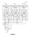
- FIG. 1is a block diagram of a lighting circuit having several dimmable light sources controlled by a single dimmer.
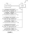
- FIG. 2is a block diagram of a light circuit according to an example embodiment of the invention in which holding current circuits in dimmable light sources can be enabled or disabled.
- FIG. 2Ais a schematic diagram illustrating an example holding current circuit that has an input for receiving an enable/disable signal.
- FIG. 2Bis a schematic diagram illustrating another example holding current circuit that has an input for receiving a signal that sets a maximum holding current draw.
- FIG. 3is a block diagram of another example embodiment of the invention in which a controller is connected to control holding current circuits in a plurality of light sources.
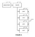
- FIG. 4is a block diagram of a lighting circuit according to another example embodiment in which light sources communicate in a peer-to-peer manner.
- FIG. 4Ais a block diagram showing a dimmable light source according to another example embodiment.
- FIGS. 5 and 5Aillustrate methods for controlling holding current circuits according to example embodiments.
- FIG. 6is a flowchart illustrating a method for controlling holding current according to another example embodiment.
- FIGS. 7A and 7Brespectively illustrate example waveforms provided by a dimmer in the case where adequate holding current is maintained and the case where the current draw is allowed to fall below the holding current required by the dimmer.
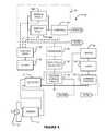
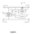
- FIG. 8is a block diagram illustrating apparatus according to another example embodiment.
- FIG. 9is a block diagram illustrating a light source according to a further alternative embodiment.
- FIG. 1shows a lighting circuit 10 which includes a number of dimmable light sources 16 .
- Light sources 16may, for example, comprise solid-state lighting units such as semiconductor light-emitting diodes (LEDs), organic light-emitting diodes (OLEDs), polymer light-emitting diodes (PLEDs) or the like.
- circuit 10is illustrated as including three light sources 16 , fewer or many more light sources 16 may be present in circuit 10 . The precise number of light sources may vary from circuit-to-circuit.
- Circuit 10is driven by AC power 12 .
- a dimmer 14of the type which requires a holding current to be drawn for proper operation is connected into the circuit.
- Light sources 16are connected in parallel. Each light source 16 receives electrical power having a waveform modified by dimmer 14 .
- each dimmable light sourcecomprises a load (for example, one or more LED light emitters) 17 .
- Electrical currentis supplied to load 17 by way of a rectifier 11 and a holding current circuit 19 .
- Holding current circuit 19ensures that the light source 16 always draws at least enough current for the proper operation of dimmer 14 .
- holding current circuit 19is of the type described in U.S. patent application Ser. No. 12/912,613 filed on 26 Oct. 2010 and entitled HIGH EFFICIENCY HOLDING CURRENT CIRCUIT FOR SOLID STATE LIGHTING APPLICATIONS which is hereby incorporated herein by reference.
- FIG. 2illustrates a lighting circuit 10 A having modified dimmable light sources 16 A, 16 B, 16 C which can be operated so as to reduce or eliminate unnecessarily large current draw arising from the operation of multiple holding current circuits 19 .
- Mains power 12 and dimmer 14are as shown in FIG. 1 .
- dimmable light sourcescomprise a lighting load 17 controlled by a control 18 .
- Control 18may, for example, determine a phase angle at which an AC power waveform is cut off by dimmer 14 and adjust the brightness of lighting load 17 based on that phase angle.
- the light sources 16also include a holding current circuit 19 .
- An enable/disable circuit 20controls the holding current circuit 19 . When holding current circuit 19 is disabled, then it draws no current or significantly reduced current.
- Circuit 10 Amay be operated so as to reduce the amount of current drawn by some or all of holding current circuits 19 in light sources 16 A, 16 B, 16 C, etc. (collectively light sources 16 ) so as to reduce the aggregate current drawn by holding current circuits 19 while still ensuring that the connected light sources 16 draw, in aggregate, a current that is at least equal to the holding current required for proper operation of dimmer 14 .
- Circuit 10 Amay comprise any number of light sources 16 up to a maximum number that can be driven by dimmer 14 .
- Light sources 16are connected to draw current from dimmer 14 in parallel. Since light sources 16 may be much more electrically efficient than conventional light sources such as incandescent bulbs or CCFL bulbs, many light sources 16 may be powered by a dimmer 14 while still providing substantial energy saving.
- FIG. 2Ashows an example holding current circuit 19 A that can be enabled or disabled by way of a control signal from another circuit.
- holding current circuit 19 AWhen holding current circuit 19 A is enabled then it draws current by way of Q 2 , as needed.
- current 21 A through a load(not shown in FIG. 2A ) is sufficiently large then the voltage at point 21 B is sufficient to turn Q 1 on, thereby pulling down the base of Q 2 so that Q 2 does not conduct.
- current through the loaddrops below a threshold value then Q 1 begins to turn off, thereby allowing Q 2 to conduct.
- Component valuesmay be selected such that the sum of the current 21 C drawn by Q 2 and current 21 A drawn by the load is equal to the required holding current.
- Holding current circuit 19 Acan be disabled when a signal received from a control 21 D by way of isolator 21 E turns FET S 1 ON. This pulls down the base of Q 1 so that Q 2 does not conduct regardless of the voltage at point 21 B, thereby disabling holding current circuit 19 A.
- FIG. 2Bshows another example holding current circuit 19 B.
- Circuit 19 Bcomprises a variable attenuator 22 .
- the impedance of variable attenuator 22which determines the maximum current that can be drawn by holding current circuit 19 B (e.g. an upper limiting current for the holding current circuit), is controlled by a controller 23 .
- Holding current circuit 19 Bdraws current when Q 3 conducts.
- Holding current circuit 19 Bmay be disabled by setting variable attenuator 22 to an open circuit or other high-impedance condition.
- variable attenuator 22is replaced by a switch controlled by controller 23 and a fixed resistor.
- Q 3is not present and controller 23 varies the attenuation provided by variable attenuator 22 to cause holding circuit 19 B to draw a dynamically variable current.
- Variable attenuator 22may be controlled so that a total current drawn by holding current circuit 19 B and one or more loads is at least equal to the holding current required by a dimmer.
- enable/disable unitse.g. enable/disable units 20 shown in FIG. 2
- a control methodis performed which disables holding current circuits 19 in all but one of the light sources that are connected to dimmer 14 .
- enable/disable circuits 20are operated to reduce the holding current drawn by some or all of holding current circuits 19 so as to reduce the aggregate amount of current drawn by the light sources 16 of circuit 10 A while still causing the light sources 16 to draw aggregate current sufficient for the proper operation of dimmer 14 (i.e. aggregate current at least equal to the holding current).
- FIG. 3shows one example in which a controller 25 is connected to receive information from each light source 16 and to provide information to light sources 16 by way of a data path 26 .
- Data path 26may, for example, comprise a wire, an optical cable, an optical link, a wireless link, a data communication protocol carried over power wires, or the like.
- Data path 26may be point-to-point, point-to-multipoint or a combination thereof.
- each light sourcereceives signals from controller 25 according to an agreed protocol. Controller 25 determines whether or not the holding current circuit in each light source should be enabled or disabled and communicates a signal to each light source which results in the holding current circuit of that light source being enabled or disabled, as appropriate. In some alternative embodiments, controller 25 may cause the task of maintaining an aggregate current draw at least equal to the holding current to be shared among different light sources.
- the holding current circuits in each of light sources 16may be controllable to vary the amount of current being drawn (either continuously or in steps) and/or the maximum current to be drawn (either continuously or in steps) and the signal from controller 25 may cause each light source 16 to set its holding current circuit to draw current such that, in aggregate, sufficient current is being drawn for the proper operation of dimmer 14 while making the total current drawn by the holding current circuits no greater than necessary.
- controller 25 and light sources 16may be configured such that light sources 16 communicate information regarding their status to controller 25 and controller 25 generates control signals for holding current circuits 19 based at least in part on information received from light sources 16 .
- Controller 25may provide other functions in addition. For example, controller 25 may control light sources 16 to change brightness and/or colour and/or turn on or off in a coordinated fashion to achieve desired lighting effects.
- FIG. 4shows an alternative embodiment in which controllers built into light sources 16 cooperate together to control holding current circuits in the light sources 16 .
- the controllers in different light sources 16communicate with one another by way of a suitable data path 26 .
- FIG. 4Aprovides a more detailed view of a dimmable light source 27 of a type which could be used in the circuits of FIG. 3 or 4 .
- Dimmable light source 27has a lighting load 17 controlled by a control 18 .
- AC power from a dimmerpowers lighting load 17 by way of a power supply 21 .
- a phase angle detector 28derives a signal from a phase at which the wave form from the dimmer is cut and supplies that signal to control 18 .
- the signalrepresents an intended dimming level.
- Control 18generates a control signal 31 for lighting load 17 based on the phase angle detected by phase angle detector 28 .
- Control signal 31may, for example, control the brightness of light emitted by lighting load 17 (or some other attribute of the light) based upon control signal 31 .
- Light source 27also includes an interface 29 which receives data from other light sources 27 and/or from a controller (such as controller 25 of FIG. 3 ).
- a signal 30 received at interface 29is provided to control 18 .
- control 18may operate enable/disable circuit 20 to enable or disable the operation of holding current circuit 19 .
- a signal 32controls the holding current circuit 19 .
- holding current circuits 19may be coordinated to maintain an aggregate current draw of at least a desired holding current in dimmer 14 .
- a light source 16may be configured to receive signals indicative of current drawn by holding current circuits associated with the other light sources and to control based at least in part on these received signals whether or not its own holding current circuit draws any additional current from dimmer 14 and/or to control an amount of additional current drawn by its own holding current circuit.
- a wide variety of methodsmay be used for controlling the operation of light sources which include holding current circuits as described above.
- the coordination controllersmay be configured to coordinate maintenance of a current draw at least equal to a holding current in dimmer 14 .
- a coordination controller of at least one light source 16may be configured to cause its associated holding current circuit to draw sufficient current for proper operation of dimmer 14 , and be configured to communicate a disable signal to a coordination controller of at least one other light source that also draws current supplied by dimmer 14 .
- the coordination controller of the at least one other light sourcemay be configured to cause its associated holding current circuit to not draw current from dimmer 14 in response to the disable signal.
- a coordination controller associated with each of a plurality of light sources 16 that draw current from a dimmer 14may be configured to: communicate its existence to coordination controllers associated with other ones of the plurality of light sources; determine, based on communications from coordination controllers of the other light sources indicating the existence of the other light sources, a number N of the plurality of light sources; and configure its associated holding current circuit so that the light source maintains a current of at least 1/N of the holding current.
- FIG. 5illustrates a method 40 according to an example embodiment.
- Method 40may be performed independently by each light source.
- the light sourcesmay, for example, comprise logic circuits or programmed data processors executing firmware or software instructions that execute method 40 when power is first applied to the light sources and/or when an initiation signal is received by the light sources.
- a holding current circuitis enabled at block 44 . While the holding current circuit in a light source is enabled, the light source transmits an “ACTIVE” signal as indicated by block 41 .
- the ACTIVE signalmay be sent periodically.
- the ACTIVE signalcan be received by other light sources.
- Block 41may be performed asynchronously of the rest of method 40 , as illustrated or, in the alternative, may be performed at specific points in the processing of method 40 .
- each light sourcelistens for an “ACTIVE” signal from other light sources.
- the ACTIVE signalindicates that another light source also has an enabled holding current circuit.
- the transmission of ACTIVE signals by block 41is inhibited during the listening of block 46 .
- Block 46is performed at different times for different light sources (e.g. light sources 16 of FIG. 2 ). In some embodiments, block 46 is performed by each light source at a random time after power on. This makes it unlikely that any two light sources will both be performing block 46 at overlapping times. Where ACTIVE signals are sent periodically, block 46 may listen for ACTIVE signals long enough to detect ACTIVE signals from any other light source that has an enabled holding current circuit and is transmitting ACTIVE signals.
- block 48it is determined whether an ACTIVE signal has been received. If block 48 determines that an ACTIVE signal has been received then, at block 50 , the holding current circuit is disabled and method 40 terminates.
- block 48determines that no ACTIVE signal was detected in block 46 then the holding current circuit remains enabled and method 40 terminates.
- Method 40implements a “last man standing” algorithm which will result in only one holding current circuit remaining active while holding current circuits in other light sources connected to the same dimmer are disabled.
- each of light sources 16 A, 16 B and 16 C of FIG. 2each perform a method like method 40 for controlling a holding current circuit 19 and are all connected to the same dimmer 14 .
- the combined effectis as follows: when circuit 10 A is initially turned on, all of holding current circuits 19 are active.
- Each of light sources 16 A, 16 B and 16 Cis configured to periodically transmit an ACTIVE signal that is received by the other ones of light sources 16 A, 16 B and 16 C.
- the ACTIVE signalmay comprise a signal imposed on power line 15 (such as, for example a high frequency spike).
- the ACTIVE signalsindicate the active state of the associated holding current circuit.
- the ACTIVE signals issued by light sources 16may be identical. It is not mandatory that ACTIVE signals from different light sources 16 are distinguishable from one another.
- Each of light sources 16 A, 16 B and 16 Cis configured to detect ACTIVE signals from the other ones of light sources 16 A, 16 B and 16 C. At different times, each of light sources 16 A, 16 B and 16 C listens for ACTIVE signals from the other light sources. If the light source detects an ACTIVE signal from another one of the light sources then it disables its associated holding current circuit 19 and stops sending ACTIVE signals.
- the first light source to listen for ACTIVE signalswill detect the ACTIVE signals being issued by one or more of the other light sources and will disable its holding current circuit and stop sending ACTIVE signals. This will occur for each light source.
- the last light source to listen for ACTIVE signals from other light sourceswill not detect ACTIVE signals in block 46 because all of the other light sources will have previously stopped transmitting ACTIVE signals. That light source will therefore execute block 51 . Execution of block 51 may disable transmission of the ACTIVE signal which is no longer required since all of the other light sources will have previously disabled their holding current circuits.
- FIG. 5shows an optional additional listening period in block 46 A.
- blocks 46 A and 48 Aare executed only if no ACTIVE signals were detected in block 46 .
- Block 46 Amay be executed at a random time after block 46 .
- Listening period 46 Aprovides a safety round.
- Block 48 Abranches depending upon whether or not an ACTIVE signal from another light source was detected in the listening period of block 46 A. This avoids the possibility that one light source will fail to detect an ACTIVE signal from another because both light sources are listening for ACTIVE signals from the other at the same time.
- one of the light sourcese.g. a light source 16 as shown in FIG. 2
- a light source 16fails to detect an ACTIVE signal in both of blocks 46 and 46 A then it can infer that it is the last light source with an active holding current circuit and can terminate method 40 leaving the holding current circuit enabled.
- blocks 46 and 46 Aare both set to occur at random times it is very unlikely that both of blocks 46 and 46 A will occur at the same time as other light sources are also listening for ACTIVE signals.
- listening periods 46 , 46 A that are appropriately long relative to the spacing of ACTIVE signals method 40may be made so as to reliably leave only one holding circuit active among a plurality of light sources and to terminate (thereby avoiding further expenditures of energy associated with transmitting ACTIVE signals, processing and other aspects of performing method 40 ).
- processingmay proceed as indicated by branch 49 .
- FIG. 5Aillustrates a method 40 A according to one particular example implementation.
- Blocks in FIG. 5Aare labeled with the same reference numbers as in FIG. 5 .
- listening block 46 and decision block 48are provided in a routine 52 that can be executed by a processor.
- a random time delayis explicitly included as block 53 in routine 52 . If routine 52 detects an ACTIVE signal from another light source (YES branch from block 48 ) in listening block 46 then the holding current circuit is disabled, the transmission of ACTIVE signals is disabled and method 40 A ends. Otherwise, block 54 determines whether listening routine 52 should be repeated.
- Block 54may, for example, include a counter that causes listening routine 52 to be executed some number of times (as long as no ACTIVE signal is detected), for example.
- method 40may periodically monitor a characteristic of the incoming power that is indicative of whether or not adequate holding current is being drawn. If the characteristic indicates that adequate holding current is not being drawn then the method may enable the holding current circuit and restart method 40 .
- method 40disables the holding current in block 50 only after ACTIVE signals from other light sources have been received twice. This avoids the possibility that the last light source with an active holding current circuit could disable its holding current circuit e.g. as a result of detecting noise that appears to be an ACTIVE signal from another light source but is not.
- a light sourceincludes a circuit that imposes periodic high frequency spikes or other characteristic signals on the power line to indicate that a holding current circuit is active in the light source. As all of the light sources are connected to the same power line, each of the light sources is able to receive the ACTIVE signals imposed on the power line by other light sources. If necessary, a filter may be connected to prevent the ACTIVE signals imposed on the power line from propagating back through a dimmer (such as dimmer 14 of FIG. 2 ) into circuits containing other light sources.
- a dimmersuch as dimmer 14 of FIG. 2
- FIG. 6illustrates one method 60 in which the current drawn by a holding current unit in a light source may be adjusted up or down over time to maintain an overall reduced draw of current.
- method 60is performed separately in multiple light sources, the result can be that the holding current required by dimmer 14 is maintained by sharing among holding current units in multiple different light sources all connected to be driven by the same dimmer 14 .
- a holding current circuit in each of the connected light sourcesis initialized at block 64 .
- the current being drawn by the holding current circuitis reduced by a small amount. The amount by which the current is reduced in block 66 may be always the same or may differ.
- a power signalis monitored for signs that the collective current being drawn by the light sources driven by a dimmer 14 is less than the required holding current.
- FIGS. 7A and 7Billustrate a possible effect of insufficient current draw.
- FIG. 7Aillustrates one positive half-cycle for a waveform 80 A supplied by dimmer 14 for the case where the current being drawn is sufficient for proper operation of a dimmer (exceeds the holding current required by the dimmer).
- the negative half-cyclewould be similar in appearance but reflected about the horizontal axis.
- Waveform 80 Ais a sinusoidal waveform except that operation of a phase cut dimmer has made a cut 81 in the leading edge of each peak 82 . Except for cut 81 in each half-wave, waveform 80 A is essentially a complete sinusoid.
- FIG. 7Bshows a contrasting waveform 80 B in which current being drawn is insufficient for proper operation of the dimmer (the current drops below the holding current in at least part of the cycle).
- the current drawn from the dimmerfell below the dimmer's holding current at point 83 resulting in the dimmer shutting off prematurely and the trailing edges 85 of the peaks of waveform 80 B being cut off.
- waveforms 80 A (of FIG. 7A) and 80B (of FIG. 7B )differ in various characteristics such as: the width of peaks 82 , the average voltage over a cycle or half-cycle, the time after the leading edge of each peak that the waveform falls below a threshold value etc. Any one or more of these characteristics may be monitored and used as an indication of whether or not adequate current is being drawn to keep the dimmer operating properly.
- One way to obtain a binary signal indicating whether or not adequate current is being drawn for a particular setting of a holding current circuitis to compare a waveform characteristic being monitored (for example average voltage over a cycle) for a case where it is known that adequate current is being drawn with the same waveform characteristic determined for the particular setting of the holding current circuit.
- the characteristicis the same in both cases then it can be inferred that the particular setting results in adequate current being drawn. Otherwise it can be inferred that the particular setting results in inadequate current being drawn by the holding current circuits to maintain a current at the dimmer at least equal to the holding current.
- the collective current being drawn by all of the light sources on the circuitwill be just adequate to maintain the current drawn from dimmer 14 at least equal to the required holding current (the amount of holding current for one dimmer 14 may be different from that which might be required by other dimmers).
- a further reduction in current drawn by the holding current circuit in any one of the light sourceswill result in a change in the signal monitored at block 68 (“YES” branch from block 70 ). In this event, control passes to loop 74 which increases the current drawn by the holding current circuit at block 76 . The power signal is again monitored at block 78 . If the signal changed (“YES” branch from block 80 ) then this indicates that at least one further small increase in current drawn by the holding current circuit should be provided to ensure that an adequate aggregate current is being drawn.
- Loops 65 and 74may be performed at a rate of once every few minutes, for example. In some embodiments, loops 65 and 74 are performed more rapidly when power is first turned on and then more slowly after a while. This permits the minimum current required for proper operation of dimmer 14 to be established soon after power is applied.
- Monitoring in block 68 and 78may be performed, for example, for a sufficient period to detect whether or not a sufficient holding current is being drawn.
- these periodsmay have a duration of approximately four half cycles of the AC waveform being provided (for example, approximately 33 milliseconds).
- light sourceshave a non-volatile memory which preserves the setting of the holding current circuit and block 64 comprises setting the holding current to the preserved setting.
- Method 40(of FIG. 5 ) or 60 (of FIG. 6 ), or variations of those methods, may be executed by means of suitably configured hardware circuits or a programmed processor for executing suitable software or firmware instructions connected to control the hardware of a light source.
- FIG. 8shows apparatus 90 according to another example embodiment.
- Apparatus 90comprises a duty cycle detector 92 and optionally a non-linear transformer (for example, an exponential amplifier) 93 that produces a control signal CTRL.
- CTRLis applied to current control 17 B that controls current through light source 17 A.
- SMPSswitching mode power supply
- Apparatus 90comprises control logic 95 driven by a clock 96 that controls a system 97 for enabling or disabling holding current circuit 19 .
- System 97comprises first and second sample and hold circuits 98 A and 98 B and a comparison unit 100 .
- Control logic 95has four stages. In a first stage, control logic 95 resets system 97 . In a second stage, control logic 95 controls first sample and hold circuit 98 A to sample CTRL over a first period of time during which holding current circuit 19 is disabled. The first period of time may, for example, comprise one cycle or 1 ⁇ 2 cycle of AC power from dimmer 14 . After the first period, the output of first sample and hold circuit 98 A is a signal representing the average of the CTRL signal over the first period.
- control logic 95controls second sample and hold circuit 98 B to sample CTRL over a second period of time during which holding current circuit 19 is enabled. After the second period, the output of second sample and hold circuit 98 B is a signal representing the average of the CTRL signal over the second period.
- control logic 95controls comparison unit 100 to compare the signals at the outputs of the first and second sample and hold circuits 98 A and 98 B.
- the output of comparison unit 100is a signal EN/DIS that indicates whether the signals at the outputs of the first and second sample and hold circuits 98 A and 98 B are the same or different.
- a differenceindicates that the holding current circuit 19 makes a difference (and is therefore required to draw current for proper operation of the dimmer). No difference indicates that holding current circuit 19 is not required to draw current.
- EN/DISis applied to control holding current circuit 19 .
- Control logic 95periodically repeats the operations described above and enables or disables holding current circuit 19 as required.
- the output of comparison unit 100may be applied to a circuit that controls the maximum current that will be drawn by the holding current circuit 19 (i.e. that controls an upper limiting current for the holding current circuit 19 ).
- the second and third stagesmay compare two different settings for holding current circuit 19 .
- the second and third stagesmay compare an active setting for the holding current circuit to a proposed setting in which the maximum current drawn by the holding current circuit is increased or decreased relative to the active setting.
- the apparatusmay be configured to make the active setting be the one of the compared settings drawing the least amount of current.
- the apparatusmay be configured to make the active setting be the one of the compared settings drawing the greater amount of current.
- holding current circuits in each of a plurality of light sourcesare configured to maintain a draw of at least a portion of the holding current required by a dimmer.
- Light sources as shown in FIG. 2may be constructed and/or configured to perform in this manner for example.
- a holding current circuit associated with each of the light sourcesmay be configured such that the light source always draws at least a current of 1/N of the holding current required.
- the portion of the holding current maintained by each of holding current circuitsis configurable.
- holding current circuits 19may comprise interfaces (e.g., physical interfaces such as switches, or the like, or electronic or electrical interfaces for receiving signals) for specifying the portion of a holding current each circuit is to maintain (e.g., a switch may be set or a signal may be provided to specify that a number N of holding current circuits are on a dimming circuit, and the holding current circuit associated with the switch is configured to automatically maintain a current drawn by the light source of at least 1/N of the required holding current).
- interfacese.g., physical interfaces such as switches, or the like, or electronic or electrical interfaces for receiving signals
- light sources 16comprise holding current circuits 19 and an interface for selectively enabling or disabling the holding current circuit 19 .
- the interfacemay comprise, for example, a manually operable switch, jumper, or electronic or electrical interfaces for receiving signals. Where a plurality of such light sources are all connected to a circuit controlled by the same dimmer, a person installing the light sources may manually configure the light sources such that holding current circuits are disabled in all but one of the light sources or all but some of the light sources.
- FIG. 9illustrates a further alternative embodiment.
- Light sources 110 as shown in FIG. 9may be daisy chained together.
- Each light source 110has contacts 111 A and 111 B for connecting to power from a dimmer and contacts 112 A and 112 B for connecting to another light source.
- Contacts 111 A and 112 Aare connected and contacts 111 B and 112 B are connected.
- currentcan pass through one light source 110 to other light sources 110 downstream.
- the light sourcesthemselves are electrically in parallel with one another.
- a current sensor 113monitors current to any downstream light sources connected to contacts 112 A and 112 B.
- a signal from current sensor 113is monitored by a control circuit 114 .
- No currentcorresponds to no downstream light sources 110 .
- controllerinhibits operation of holding current circuit 19 as long as current sensor 113 detects current being supplied to one or more downstream light sources 110 .
- the holding current circuit 19 in the light source 110 at the end of a chainwill be enabled while the holding circuits 19 in light sources 110 that are upstream will be inhibited.
- light sourcesinclude a phase angle detector which can be turned on or off and a control which can use information received from a source outside of the light source in place of a signal from the phase angle detector when the phase angle detector is turned off.
- FIG. 4Ashows a phase angle detector 28 which can be turned on or off by a control signal 34 from control 18 .
- Some phase angle detector circuitsconsume a small amount of power in operation. Since the phase angle will be the same for all light sources 27 connected to the same dimmer (e.g. a dimmer 14 as shown in FIG. 4 ), it is only necessary to perform phase angle detection once.
- control 18may be configured to keep phase angle detector 28 inoperative (and consuming all or reduced power) as long as phase angle information from a source external to the light source is being received at interface 29 .
- light sources as described hereinare packaged to have a form factor similar to that of a standard incandescent or CCFL bulb with a base suitable for connection to a standard receptacle. Such light sources may be installed as a direct replacement for incandescent, CCFL or other less energy-efficient light sources.
- phase angle detectorit is not mandatory to use a phase angle detector to obtain a signal to be used for controlling light sources as described herein.
- Other measurementsmay be used to determine a desired dimming level. For example any of phase angle, average voltage or other suitable characteristic may be monitored to ascertain a desired dimming level.
Landscapes
- Circuit Arrangement For Electric Light Sources In General (AREA)
Abstract
Description
Claims (16)
Applications Claiming Priority (6)
| Application Number | Priority Date | Filing Date | Title |
|---|---|---|---|
| US27975009P | 2009-10-26 | 2009-10-26 | |
| US33990710P | 2010-03-11 | 2010-03-11 | |
| US36316110P | 2010-07-09 | 2010-07-09 | |
| CAPCT/CA2010/001677 | 2010-10-26 | ||
| WOPCT/CA2010/001677 | 2010-10-26 | ||
| PCT/CA2010/001677WO2011050453A1 (en) | 2009-10-26 | 2010-10-26 | Holding current circuits for phase-cut power control |
Publications (2)
| Publication Number | Publication Date |
|---|---|
| US20110266974A1 US20110266974A1 (en) | 2011-11-03 |
| US8339066B2true US8339066B2 (en) | 2012-12-25 |
Family
ID=43921195
Family Applications (2)
| Application Number | Title | Priority Date | Filing Date |
|---|---|---|---|
| US12/912,613Active2030-11-12US8283875B2 (en) | 2009-10-26 | 2010-10-26 | Holding current circuits for phase-cut power control |
| US13/072,638ActiveUS8339066B2 (en) | 2009-10-26 | 2011-03-25 | Energy saving lighting systems and units providing coordinated operation of holding current units |
Family Applications Before (1)
| Application Number | Title | Priority Date | Filing Date |
|---|---|---|---|
| US12/912,613Active2030-11-12US8283875B2 (en) | 2009-10-26 | 2010-10-26 | Holding current circuits for phase-cut power control |
Country Status (4)
| Country | Link |
|---|---|
| US (2) | US8283875B2 (en) |
| EP (1) | EP2494851A1 (en) |
| CN (1) | CN102577624B (en) |
| WO (1) | WO2011050453A1 (en) |
Cited By (6)
| Publication number | Priority date | Publication date | Assignee | Title |
|---|---|---|---|---|
| US20110241566A1 (en)* | 2010-04-06 | 2011-10-06 | Osram Gesellschaft Mit Beschraenkter Haftung | Power supply device for light sources, such as halogen lamps, and related method |
| US9247608B2 (en) | 2013-11-08 | 2016-01-26 | Lutron Electronics Co., Inc. | Load control device for a light-emitting diode light source |
| US9565731B2 (en) | 2015-05-01 | 2017-02-07 | Lutron Electronics Co., Inc. | Load control device for a light-emitting diode light source |
| US9655180B2 (en) | 2015-06-19 | 2017-05-16 | Lutron Electronics Co., Inc. | Load control device for a light-emitting diode light source |
| US10098196B2 (en) | 2016-09-16 | 2018-10-09 | Lutron Electronics Co., Inc. | Load control device for a light-emitting diode light source having different operating modes |
| US12446131B2 (en) | 2024-07-10 | 2025-10-14 | Lutron Technology Company Llc | Load control device for a light-emitting diode light source |
Families Citing this family (69)
| Publication number | Priority date | Publication date | Assignee | Title |
|---|---|---|---|---|
| US7667408B2 (en) | 2007-03-12 | 2010-02-23 | Cirrus Logic, Inc. | Lighting system with lighting dimmer output mapping |
| US7288902B1 (en) | 2007-03-12 | 2007-10-30 | Cirrus Logic, Inc. | Color variations in a dimmable lighting device with stable color temperature light sources |
| US9155174B2 (en) | 2009-09-30 | 2015-10-06 | Cirrus Logic, Inc. | Phase control dimming compatible lighting systems |
| US9220133B2 (en)* | 2009-11-20 | 2015-12-22 | Lutron Electronics Co., Inc. | Controllable-load circuit for use with a load control device |
| US8334658B2 (en)* | 2010-06-30 | 2012-12-18 | Power Integrations, Inc. | Dimmer-disabled LED driver |
| US8536799B1 (en) | 2010-07-30 | 2013-09-17 | Cirrus Logic, Inc. | Dimmer detection |
| US8729811B2 (en) | 2010-07-30 | 2014-05-20 | Cirrus Logic, Inc. | Dimming multiple lighting devices by alternating energy transfer from a magnetic storage element |
| CN103155387B (en) | 2010-07-30 | 2016-10-19 | 皇家飞利浦有限公司 | Powering Efficient Lighting Fixtures from Triac-Based Dimmers |
| US9307601B2 (en) | 2010-08-17 | 2016-04-05 | Koninklijke Philips N.V. | Input voltage sensing for a switching power converter and a triac-based dimmer |
| US8847515B2 (en) | 2010-08-24 | 2014-09-30 | Cirrus Logic, Inc. | Multi-mode dimmer interfacing including attach state control |
| EP2636139A2 (en) | 2010-11-04 | 2013-09-11 | Cirrus Logic, Inc. | Controlled energy dissipation in a switching power converter |
| WO2012061454A2 (en) | 2010-11-04 | 2012-05-10 | Cirrus Logic, Inc. | Duty factor probing of a triac-based dimmer |
| CN103262399B (en) | 2010-11-04 | 2017-02-15 | 皇家飞利浦有限公司 | Method and device for controlling energy dissipation in switch power converter |
| DK2681969T3 (en) | 2010-11-16 | 2019-03-25 | Signify Holding Bv | REAR EDGE COMPATIBILITY WITH PREVENTION OF HIGH DUMPING RESISTANCE |
| US9025347B2 (en) | 2010-12-16 | 2015-05-05 | Cirrus Logic, Inc. | Switching parameter based discontinuous mode-critical conduction mode transition |
| CN103621182B (en) | 2011-06-10 | 2016-06-08 | 皇家飞利浦有限公司 | Led light source |
| WO2013003673A1 (en) | 2011-06-30 | 2013-01-03 | Cirrus Logic, Inc. | Transformer-isolated led lighting circuit with secondary-side dimming control |
| TWI441428B (en)* | 2011-07-06 | 2014-06-11 | Macroblock Inc | Auto-selecting holding current circuit |
| US9142962B2 (en)* | 2011-08-29 | 2015-09-22 | Control4 Corporation | Wall box device for managing energy |
| US9293919B2 (en)* | 2011-08-29 | 2016-03-22 | Control4 Corporation | Systems and methods for inductive load switching |
| US8749174B2 (en)* | 2011-08-31 | 2014-06-10 | Power Integrations, Inc. | Load current management circuit |
| BR112014008524A2 (en)* | 2011-10-14 | 2017-04-18 | Koninklijke Philips Nv | method of determining the amount of light generation from a solid state lighting unit, and, solid state lighting unit configured to connect to a dimmer in a dimmer circuit |
| RU2611427C2 (en)* | 2011-11-04 | 2017-02-22 | Филипс Лайтинг Холдинг Б.В. | Control device and method of load control with polarity-dependent voltage divider circuit |
| US8698407B1 (en)* | 2011-11-14 | 2014-04-15 | Technical Consumer Products, Inc. | Highly integrated non-inductive LED driver |
| CN102497695A (en)* | 2011-11-18 | 2012-06-13 | 上海晶丰明源半导体有限公司 | LED linear constant current control circuit and LED linear circuit |
| EP2792037A2 (en) | 2011-12-14 | 2014-10-22 | Cirrus Logic, Inc. | Multi-mode flyback control for a switching power converter with dimmer |
| RU2669381C2 (en) | 2012-01-06 | 2018-10-11 | Филипс Лайтинг Холдинг Б.В. | Electrical device and method for compensating an effect of an electrical current of a load, in particular a led unit, and driver device for driving a load, in particular a led unit |
| EP2820919A1 (en) | 2012-02-29 | 2015-01-07 | Cirrus Logic, Inc. | Mixed load current compensation for led lighting |
| US9101015B2 (en) | 2012-03-13 | 2015-08-04 | Dialog Semiconductor Inc. | Adaptive bipolar junction transistor gain detection |
| USRE50126E1 (en)* | 2012-03-15 | 2024-09-17 | Signify Holding B.V. | Shunt device in lighting control system without neutral wire |
| US9736898B2 (en)* | 2012-03-23 | 2017-08-15 | Texas Instruments Incorporated | Circuit and method for driving a light-emitting diode |
| US9520794B2 (en) | 2012-07-25 | 2016-12-13 | Philips Lighting Holding B.V | Acceleration of output energy provision for a load during start-up of a switching power converter |
| JP6048725B2 (en)* | 2012-07-27 | 2016-12-21 | 東芝ライテック株式会社 | Detection circuit |
| US9184661B2 (en) | 2012-08-27 | 2015-11-10 | Cirrus Logic, Inc. | Power conversion with controlled capacitance charging including attach state control |
| CN103889097B (en)* | 2012-12-21 | 2017-07-04 | 施耐德电气(澳大利亚)有限公司 | A kind of dimming controlling method, device and light adjusting system |
| US9496844B1 (en) | 2013-01-25 | 2016-11-15 | Koninklijke Philips N.V. | Variable bandwidth filter for dimmer phase angle measurements |
| WO2014159456A1 (en)* | 2013-03-12 | 2014-10-02 | Power Integrations, Inc. | Integrated current controller for maintaining holding current of a dimmer circuit |
| WO2014152933A1 (en) | 2013-03-14 | 2014-09-25 | Cirrus Logic, Inc. | Controlled electronic system power dissipation via an auxiliary-power dissipation circuit |
| US20140265898A1 (en)* | 2013-03-15 | 2014-09-18 | Power Integrations, Inc. | Lossless preload for led driver with extended dimming |
| US9282598B2 (en) | 2013-03-15 | 2016-03-08 | Koninklijke Philips N.V. | System and method for learning dimmer characteristics |
| US11083067B2 (en)* | 2013-03-15 | 2021-08-03 | Hatch Transformers, Inc. | Electrical power supply with removable plug-in cartridge |
| US9490611B2 (en) | 2013-04-18 | 2016-11-08 | Abl Ip Holding Llc | Universal load control cabinet |
| US8829819B1 (en) | 2013-05-07 | 2014-09-09 | Power Integrations, Inc. | Enhanced active preload for high performance LED driver with extended dimming |
| US10591120B2 (en) | 2015-05-29 | 2020-03-17 | DMF, Inc. | Lighting module for recessed lighting systems |
| US10563850B2 (en) | 2015-04-22 | 2020-02-18 | DMF, Inc. | Outer casing for a recessed lighting fixture |
| US9964266B2 (en) | 2013-07-05 | 2018-05-08 | DMF, Inc. | Unified driver and light source assembly for recessed lighting |
| US9572207B2 (en)* | 2013-08-14 | 2017-02-14 | Infineon Technologies Austria Ag | Dimming range extension |
| US9648676B2 (en) | 2013-11-19 | 2017-05-09 | Power Integrations, Inc. | Bleeder circuit emulator for a power converter |
| CN103607825B (en)* | 2013-11-26 | 2015-07-29 | 矽力杰半导体技术(杭州)有限公司 | Thyristor regulating optical circuit and dimming controlling method |
| US9621062B2 (en) | 2014-03-07 | 2017-04-11 | Philips Lighting Holding B.V. | Dimmer output emulation with non-zero glue voltage |
| JP6266126B2 (en)* | 2014-03-24 | 2018-01-24 | フィリップス ライティング ホールディング ビー ヴィ | Radio frequency (RF) control lamp for dimmers |
| US9215772B2 (en) | 2014-04-17 | 2015-12-15 | Philips International B.V. | Systems and methods for minimizing power dissipation in a low-power lamp coupled to a trailing-edge dimmer |
| US9332614B2 (en)* | 2014-09-29 | 2016-05-03 | Power Integrations, Inc. | LED driver circuit with open load detection |
| US10361637B2 (en)* | 2015-03-20 | 2019-07-23 | Hubbell Incorporated | Universal input electronic transformer |
| CN104851726B (en)* | 2015-05-11 | 2018-03-30 | 广东小天才科技有限公司 | Key structure and electronic equipment with same |
| WO2017106598A1 (en)* | 2015-12-16 | 2017-06-22 | Black Tank, Llc | Lighting system and method for pwm adjustable current control |
| US10097010B2 (en)* | 2016-04-19 | 2018-10-09 | Infineon Technologies Ag | Control of freewheeling voltage |
| CN106093519A (en)* | 2016-06-03 | 2016-11-09 | 厦门市星云睿自动化科技有限公司 | Electroplating current based on ZigBee monitoring system |
| WO2018209273A1 (en)* | 2017-05-11 | 2018-11-15 | ERP Power, LLC | Active preload for triac dimmers |
| CN107155235B (en)* | 2017-05-23 | 2020-02-14 | 深圳迈睿智能科技有限公司 | Method and circuit for maintaining minimum conduction angle of silicon controlled rectifier dimming |
| US10488000B2 (en) | 2017-06-22 | 2019-11-26 | DMF, Inc. | Thin profile surface mount lighting apparatus |
| WO2019147740A1 (en) | 2018-01-23 | 2019-08-01 | DMF, Inc. | Methods and apparatus for triac-based dimming of leds |
| CN110582136B (en)* | 2018-06-08 | 2024-08-02 | 美芯晟科技(北京)股份有限公司 | Dimmable LED driving circuit and control method |
| USD903605S1 (en) | 2018-06-12 | 2020-12-01 | DMF, Inc. | Plastic deep electrical junction box |
| US10398004B1 (en)* | 2018-07-06 | 2019-08-27 | Elb Electronics, Inc. | LED fluorescent lamp emulator circuitry |
| USD864877S1 (en) | 2019-01-29 | 2019-10-29 | DMF, Inc. | Plastic deep electrical junction box with a lighting module mounting yoke |
| CA3191629A1 (en) | 2020-09-09 | 2022-03-17 | Russikesh Kumar | Apparatus and methods for communicating information and power via phase-cut ac waveforms |
| CN112584577A (en)* | 2020-12-25 | 2021-03-30 | 无锡安特源科技股份有限公司 | A hold current circuit for cutting looks light modulation power |
| CN114205963A (en)* | 2021-12-21 | 2022-03-18 | 欧普照明股份有限公司 | Linear LED driving circuit and driving method |
Citations (19)
| Publication number | Priority date | Publication date | Assignee | Title |
|---|---|---|---|---|
| GB1146776A (en) | 1967-08-28 | 1969-03-26 | Richard Lawrence Godfrey | Improvements in electrical control units |
| US5652481A (en) | 1994-06-10 | 1997-07-29 | Beacon Light Products, Inc. | Automatic state tranition controller for a fluorescent lamp |
| WO1999045750A1 (en) | 1998-03-04 | 1999-09-10 | Koninklijke Philips Electronics N.V. | Triac dimmable ballast |
| US5955847A (en) | 1994-06-10 | 1999-09-21 | Beacon Light Products, Inc. | Method for dimming a fluorescent lamp |
| WO2001001385A1 (en) | 1999-06-29 | 2001-01-04 | Welles Reymond | Ac powered led circuits for traffic signal displays |
| US20030197497A1 (en) | 2001-04-18 | 2003-10-23 | Linear Technology Corporation | Constant-current/constant-voltage circuit architecture |
| US6834002B2 (en) | 2003-01-31 | 2004-12-21 | Entrust Power Co., Ltd. | Power factor correction circuit |
| WO2005115058A1 (en) | 2004-05-19 | 2005-12-01 | Goeken Group Corp. | Dimming circuit for led lighting device with means for holding triac in conduction |
| US7102902B1 (en) | 2005-02-17 | 2006-09-05 | Ledtronics, Inc. | Dimmer circuit for LED |
| WO2009101544A2 (en) | 2008-02-12 | 2009-08-20 | Philips Intellectual Property & Standards Gmbh | Control circuit of a dimmer assembly for dimming an energy-saving lamp |
| WO2010027254A1 (en) | 2008-09-05 | 2010-03-11 | Eldolab Holding B.V. | Led based lighting application |
| US7696698B2 (en) | 2007-12-31 | 2010-04-13 | Lumination Llc | LEDs tricolor power signal |
| US20100090618A1 (en) | 2008-04-04 | 2010-04-15 | Lemnis Lighting Ip Gmbh | Dimmable lighting system |
| US7902769B2 (en) | 2006-01-20 | 2011-03-08 | Exclara, Inc. | Current regulator for modulating brightness levels of solid state lighting |
| US20110068706A1 (en)* | 2009-09-18 | 2011-03-24 | Toshiba Lighting & Technology Corporation | Led lighting device and illumination apparatus |
| US20110084622A1 (en) | 2009-10-14 | 2011-04-14 | National Semiconductor Corporation | Dimmer decoder with low duty cycle handling for use with led drivers |
| US20110121744A1 (en)* | 2009-11-20 | 2011-05-26 | Lutron Electronics Co., Inc. | Controllable-load circuit for use with a load control device |
| US20110140620A1 (en)* | 2010-07-12 | 2011-06-16 | Lin Yung Lin | Circuits and methods for controlling dimming of a light source |
| US7978485B2 (en)* | 2007-05-04 | 2011-07-12 | Stmicroelectronics, Inc. | Thyristor power control circuit with damping circuit maintaining thyristor holding current |
Family Cites Families (1)
| Publication number | Priority date | Publication date | Assignee | Title |
|---|---|---|---|---|
| US7656103B2 (en)* | 2006-01-20 | 2010-02-02 | Exclara, Inc. | Impedance matching circuit for current regulation of solid state lighting |
- 2010
- 2010-10-26WOPCT/CA2010/001677patent/WO2011050453A1/enactiveApplication Filing
- 2010-10-26CNCN201080047431.3Apatent/CN102577624B/enactiveActive
- 2010-10-26EPEP10825884Apatent/EP2494851A1/ennot_activeWithdrawn
- 2010-10-26USUS12/912,613patent/US8283875B2/enactiveActive
- 2011
- 2011-03-25USUS13/072,638patent/US8339066B2/enactiveActive
Patent Citations (21)
| Publication number | Priority date | Publication date | Assignee | Title |
|---|---|---|---|---|
| GB1146776A (en) | 1967-08-28 | 1969-03-26 | Richard Lawrence Godfrey | Improvements in electrical control units |
| US5652481A (en) | 1994-06-10 | 1997-07-29 | Beacon Light Products, Inc. | Automatic state tranition controller for a fluorescent lamp |
| US5955847A (en) | 1994-06-10 | 1999-09-21 | Beacon Light Products, Inc. | Method for dimming a fluorescent lamp |
| WO1999045750A1 (en) | 1998-03-04 | 1999-09-10 | Koninklijke Philips Electronics N.V. | Triac dimmable ballast |
| WO2001001385A1 (en) | 1999-06-29 | 2001-01-04 | Welles Reymond | Ac powered led circuits for traffic signal displays |
| US20030197497A1 (en) | 2001-04-18 | 2003-10-23 | Linear Technology Corporation | Constant-current/constant-voltage circuit architecture |
| US6834002B2 (en) | 2003-01-31 | 2004-12-21 | Entrust Power Co., Ltd. | Power factor correction circuit |
| WO2005115058A1 (en) | 2004-05-19 | 2005-12-01 | Goeken Group Corp. | Dimming circuit for led lighting device with means for holding triac in conduction |
| US20080258647A1 (en) | 2004-05-19 | 2008-10-23 | Goeken Group Corp. | Dimming Circuit for Led Lighting Device With Means for Holding Triac in Conduction |
| US7102902B1 (en) | 2005-02-17 | 2006-09-05 | Ledtronics, Inc. | Dimmer circuit for LED |
| US7902769B2 (en) | 2006-01-20 | 2011-03-08 | Exclara, Inc. | Current regulator for modulating brightness levels of solid state lighting |
| US7978485B2 (en)* | 2007-05-04 | 2011-07-12 | Stmicroelectronics, Inc. | Thyristor power control circuit with damping circuit maintaining thyristor holding current |
| US7696698B2 (en) | 2007-12-31 | 2010-04-13 | Lumination Llc | LEDs tricolor power signal |
| WO2009101544A2 (en) | 2008-02-12 | 2009-08-20 | Philips Intellectual Property & Standards Gmbh | Control circuit of a dimmer assembly for dimming an energy-saving lamp |
| US20100090618A1 (en) | 2008-04-04 | 2010-04-15 | Lemnis Lighting Ip Gmbh | Dimmable lighting system |
| WO2010027254A1 (en) | 2008-09-05 | 2010-03-11 | Eldolab Holding B.V. | Led based lighting application |
| US20110068706A1 (en)* | 2009-09-18 | 2011-03-24 | Toshiba Lighting & Technology Corporation | Led lighting device and illumination apparatus |
| US20110084622A1 (en) | 2009-10-14 | 2011-04-14 | National Semiconductor Corporation | Dimmer decoder with low duty cycle handling for use with led drivers |
| US20110115395A1 (en) | 2009-10-14 | 2011-05-19 | National Semiconductor Corporation | Dimmer decoder with improved efficiency for use with led drivers |
| US20110121744A1 (en)* | 2009-11-20 | 2011-05-26 | Lutron Electronics Co., Inc. | Controllable-load circuit for use with a load control device |
| US20110140620A1 (en)* | 2010-07-12 | 2011-06-16 | Lin Yung Lin | Circuits and methods for controlling dimming of a light source |
Non-Patent Citations (1)
| Title |
|---|
| "LM3445 Off-Line TRIAC Dimmer LED Driver Demo Board", National Semiconductor Corporation, Application Note 1935, Apr. 14, 2009. |
Cited By (37)
| Publication number | Priority date | Publication date | Assignee | Title |
|---|---|---|---|---|
| US20110241566A1 (en)* | 2010-04-06 | 2011-10-06 | Osram Gesellschaft Mit Beschraenkter Haftung | Power supply device for light sources, such as halogen lamps, and related method |
| US8502518B2 (en)* | 2010-04-06 | 2013-08-06 | Osram Gesellschaft Mit Beschraenkter Haftung | Power supply device for light sources, such as halogen lamps, and related method |
| US12069784B2 (en) | 2013-11-08 | 2024-08-20 | Lutron Technology Company Llc | Load control device for a light-emitting diode light source |
| US9247608B2 (en) | 2013-11-08 | 2016-01-26 | Lutron Electronics Co., Inc. | Load control device for a light-emitting diode light source |
| US10966299B2 (en) | 2013-11-08 | 2021-03-30 | Lutron Technology Company Llc | Load control device for a light-emitting diode light source |
| US11317491B2 (en) | 2013-11-08 | 2022-04-26 | Lutron Technology Company Llc | Load control device for a light-emitting diode light source |
| US10375781B2 (en) | 2013-11-08 | 2019-08-06 | Lutron Technology Company Llc | Load control device for a light-emitting diode light source |
| US9888535B2 (en) | 2013-11-08 | 2018-02-06 | Lutron Electronics Co., Inc. | Load control device for a light-emitting diode light source |
| US10652980B2 (en) | 2013-11-08 | 2020-05-12 | Lutron Technology Company Llc | Circuits and methods for controlling an intensity of a light-emitting diode light source |
| US11711875B2 (en) | 2013-11-08 | 2023-07-25 | Lutron Technology Company Llc | Load control device for a light-emitting diode light source |
| US10136484B2 (en) | 2013-11-08 | 2018-11-20 | Lutron Electronics Co., Inc. | Load control device for a light-emitting diode light source |
| US9538600B2 (en) | 2013-11-08 | 2017-01-03 | Lutron Electronics Co., Inc. | Load control device for a light-emitting diode light source |
| US10194501B2 (en) | 2015-05-01 | 2019-01-29 | Lutron Electronics Co., Inc. | Load control device for a light-emitting diode light source |
| US11388791B2 (en) | 2015-05-01 | 2022-07-12 | Lutron Technology Company Llc | Load control device for a light-emitting diode light source |
| US9888540B2 (en) | 2015-05-01 | 2018-02-06 | Lutron Electronics Co., Inc. | Load control device for a light-emitting diode light source |
| US10455659B2 (en) | 2015-05-01 | 2019-10-22 | Lutron Technology Company Llc | Load control device for a light-emitting diode light source |
| US12075532B2 (en) | 2015-05-01 | 2024-08-27 | Lutron Technology Company Llc | Load control device for a light-emitting diode light source |
| US9565731B2 (en) | 2015-05-01 | 2017-02-07 | Lutron Electronics Co., Inc. | Load control device for a light-emitting diode light source |
| US10827577B2 (en) | 2015-05-01 | 2020-11-03 | Lutron Technology Company Llc | Load control device for a light-emitting diode light source |
| US11653427B2 (en) | 2015-06-19 | 2023-05-16 | Lutron Technology Company Llc | Load control device for a light-emitting diode light source |
| US10104735B2 (en) | 2015-06-19 | 2018-10-16 | Lutron Electronics Co., Inc. | Load control device for a light-emitting diode light source |
| US10609777B2 (en) | 2015-06-19 | 2020-03-31 | Lutron Technology Company Llc | Load control device for a light-emitting diode light source |
| US12356519B2 (en) | 2015-06-19 | 2025-07-08 | Lutron Technology Company Llc | Load control device for a light-emitting diode light source |
| US11109456B2 (en) | 2015-06-19 | 2021-08-31 | Lutron Technology Company Llc | Load control device for a light-emitting diode light source |
| US9655180B2 (en) | 2015-06-19 | 2017-05-16 | Lutron Electronics Co., Inc. | Load control device for a light-emitting diode light source |
| US12022582B2 (en) | 2015-06-19 | 2024-06-25 | Lutron Technology Company Llc | Load control device for a light-emitting diode light source |
| US10356868B2 (en) | 2015-06-19 | 2019-07-16 | Lutron Technology Company Llc | Load control device for a light-emitting diode light source |
| US11678416B2 (en) | 2016-09-16 | 2023-06-13 | Lutron Technology Company Llc | Load control device for a light-emitting diode light source having different operating modes |
| US10652978B2 (en) | 2016-09-16 | 2020-05-12 | Lutron Technology Company Llc | Load control device for a light-emitting diode light source having different operating modes |
| US10306723B2 (en) | 2016-09-16 | 2019-05-28 | Lutron Technology Company Llc | Load control device for a light-emitting diode light source having different operating modes |
| US11950336B2 (en) | 2016-09-16 | 2024-04-02 | Lutron Technology Company Llc | Load control device for a light-emitting diode light source having different operating modes |
| US10462867B2 (en) | 2016-09-16 | 2019-10-29 | Lutron Technology Company Llc | Load control device for a light-emitting diode light source having different operating modes |
| US10098196B2 (en) | 2016-09-16 | 2018-10-09 | Lutron Electronics Co., Inc. | Load control device for a light-emitting diode light source having different operating modes |
| US11291093B2 (en) | 2016-09-16 | 2022-03-29 | Lutron Technology Company Llc | Load control device for a light-emitting diode light source having different operating modes |
| US10986709B2 (en) | 2016-09-16 | 2021-04-20 | Lutron Technology Company Llc | Load control device for a light-emitting diode light source having different operating modes |
| US12414210B2 (en) | 2016-09-16 | 2025-09-09 | Lutron Technology Company Llc | Load control device for a light-emitting diode light source having different operating modes |
| US12446131B2 (en) | 2024-07-10 | 2025-10-14 | Lutron Technology Company Llc | Load control device for a light-emitting diode light source |
Also Published As
| Publication number | Publication date |
|---|---|
| CN102577624A (en) | 2012-07-11 |
| CN102577624B (en) | 2015-01-07 |
| US20110241557A1 (en) | 2011-10-06 |
| US8283875B2 (en) | 2012-10-09 |
| US20110266974A1 (en) | 2011-11-03 |
| EP2494851A1 (en) | 2012-09-05 |
| WO2011050453A1 (en) | 2011-05-05 |
Similar Documents
| Publication | Publication Date | Title |
|---|---|---|
| US8339066B2 (en) | Energy saving lighting systems and units providing coordinated operation of holding current units | |
| US11297701B2 (en) | Switch based lighting control | |
| US10187951B2 (en) | Toggle control for lighting system | |
| JP5956027B2 (en) | Method and apparatus for operating high power LED group | |
| US12075535B2 (en) | Load control device configured to operate in two-wire and three-wire modes | |
| US8694807B2 (en) | Load control device having a microprocessor for monitoring an internal power supply | |
| US8892913B2 (en) | Load control device having a low-power mode | |
| US9900963B1 (en) | Lighting controller | |
| US7336463B2 (en) | Device and method for dimming service loads | |
| US10321532B2 (en) | Power factor dimming | |
| CN104582142A (en) | Stepless dimming control method for lighting system | |
| WO2021146984A1 (en) | Illumination apparatus and illumination control system thereof | |
| CN110572895B (en) | Primary and secondary lighting device, control method of primary and secondary lighting device and intelligent lighting system | |
| JP2008206086A (en) | Visible optical communication system | |
| JP6389460B2 (en) | Power supply | |
| US11083071B2 (en) | Method for monitoring power consumption of a load coupled to a power switch | |
| CN105453699B (en) | Dimmable led illuminant system | |
| CN111295016A (en) | Dimming method and system of single-live-wire dimming device | |
| JP6463865B1 (en) | Load control system and load control device | |
| US11445586B2 (en) | Adaptive power balancing in LED lamps | |
| EP3892066B1 (en) | Automatic trimming for a dimmer switch | |
| CN210518935U (en) | Lamp fitting | |
| CN220733059U (en) | DALI dimming system capable of being rapidly configured | |
| TWM572618U (en) | Light emitting diode illumination device and dimming module |
Legal Events
| Date | Code | Title | Description |
|---|---|---|---|
| AS | Assignment | Owner name:LIGHT-BASED TECHNOLOGIES INCORPORATED, CANADA Free format text:ASSIGNMENT OF ASSIGNORS INTEREST;ASSIGNORS:THORNTON, TOM WILLIAM;MOUSSAKOV, MILEN;SHEEHAN, GREGORY BERNARD;REEL/FRAME:026293/0962 Effective date:20110425 | |
| STCF | Information on status: patent grant | Free format text:PATENTED CASE | |
| AS | Assignment | Owner name:KONINKLIJKE PHILIPS ELECTRONICS N V, NETHERLANDS Free format text:ASSIGNMENT OF ASSIGNORS INTEREST;ASSIGNOR:LIGHT-BASED TECHNOLOGIES INCORPORATED;REEL/FRAME:032559/0908 Effective date:20140211 | |
| AS | Assignment | Owner name:KONINKLIJKE PHILIPS N.V., NETHERLANDS Free format text:ASSIGNMENT OF ASSIGNORS INTEREST;ASSIGNOR:LIGHT-BASED TECHNOLOGIES INCORPORATED;REEL/FRAME:032827/0342 Effective date:20140211 | |
| FEPP | Fee payment procedure | Free format text:PAT HOLDER NO LONGER CLAIMS SMALL ENTITY STATUS, ENTITY STATUS SET TO UNDISCOUNTED (ORIGINAL EVENT CODE: STOL); ENTITY STATUS OF PATENT OWNER: LARGE ENTITY | |
| FPAY | Fee payment | Year of fee payment:4 | |
| AS | Assignment | Owner name:PHILIPS LIGHTING HOLDING B.V., NETHERLANDS Free format text:ASSIGNMENT OF ASSIGNORS INTEREST;ASSIGNOR:KONINKLIJKE PHILIPS N.V.;REEL/FRAME:040060/0009 Effective date:20160607 | |
| AS | Assignment | Owner name:SIGNIFY HOLDING B.V., NETHERLANDS Free format text:CHANGE OF NAME;ASSIGNOR:PHILIPS LIGHTING HOLDING B.V.;REEL/FRAME:050837/0576 Effective date:20190201 | |
| MAFP | Maintenance fee payment | Free format text:PAYMENT OF MAINTENANCE FEE, 8TH YEAR, LARGE ENTITY (ORIGINAL EVENT CODE: M1552); ENTITY STATUS OF PATENT OWNER: LARGE ENTITY Year of fee payment:8 | |
| MAFP | Maintenance fee payment | Free format text:PAYMENT OF MAINTENANCE FEE, 12TH YEAR, LARGE ENTITY (ORIGINAL EVENT CODE: M1553); ENTITY STATUS OF PATENT OWNER: LARGE ENTITY Year of fee payment:12 |