US8337557B2 - Apparatus and kit for injecting a curable biomaterial into an intervertebral space - Google Patents
Apparatus and kit for injecting a curable biomaterial into an intervertebral spaceDownload PDFInfo
- Publication number
- US8337557B2 US8337557B2US11/170,657US17065705AUS8337557B2US 8337557 B2US8337557 B2US 8337557B2US 17065705 AUS17065705 AUS 17065705AUS 8337557 B2US8337557 B2US 8337557B2
- Authority
- US
- United States
- Prior art keywords
- cannula
- annulus
- kit
- needle
- disc
- Prior art date
- Legal status (The legal status is an assumption and is not a legal conclusion. Google has not performed a legal analysis and makes no representation as to the accuracy of the status listed.)
- Expired - Fee Related, expires
Links
- 239000012620biological materialSubstances0.000titleclaimsabstractdescription50
- 238000002347injectionMethods0.000claimsabstractdescription121
- 239000007924injectionSubstances0.000claimsabstractdescription121
- 229920000642polymerPolymers0.000claimsabstractdescription24
- 102000004169proteins and genesHuman genes0.000claimsabstractdescription7
- 108090000623proteins and genesProteins0.000claimsabstractdescription7
- 230000001070adhesive effectEffects0.000claimsabstractdescription5
- 239000000463materialSubstances0.000claimsdescription70
- 238000003032molecular dockingMethods0.000claimsdescription33
- 238000003780insertionMethods0.000claimsdescription12
- 230000037431insertionEffects0.000claimsdescription12
- 238000000034methodMethods0.000description62
- 239000012530fluidSubstances0.000description29
- 238000002156mixingMethods0.000description21
- 239000002872contrast mediaSubstances0.000description17
- 206010061246Intervertebral disc degenerationDiseases0.000description14
- FAPWRFPIFSIZLT-UHFFFAOYSA-MSodium chlorideChemical compound[Na+].[Cl-]FAPWRFPIFSIZLT-UHFFFAOYSA-M0.000description14
- 208000018180degenerative disc diseaseDiseases0.000description14
- 208000021600intervertebral disc degenerative diseaseDiseases0.000description14
- 238000001356surgical procedureMethods0.000description11
- 210000001519tissueAnatomy0.000description11
- 239000004971Cross linkerSubstances0.000description9
- 238000013459approachMethods0.000description9
- 238000012360testing methodMethods0.000description9
- 238000011282treatmentMethods0.000description9
- 239000000470constituentSubstances0.000description8
- 238000011065in-situ storageMethods0.000description7
- 238000007789sealingMethods0.000description7
- 238000002594fluoroscopyMethods0.000description6
- 210000003041ligamentAnatomy0.000description5
- 238000010276constructionMethods0.000description4
- 238000012986modificationMethods0.000description4
- 230000004048modificationEffects0.000description4
- 230000008569processEffects0.000description4
- 208000003618Intervertebral Disc DisplacementDiseases0.000description3
- 241000283984RodentiaSpecies0.000description3
- 230000008901benefitEffects0.000description3
- 229940039231contrast mediaDrugs0.000description3
- 238000005516engineering processMethods0.000description3
- 230000004927fusionEffects0.000description3
- 238000003384imaging methodMethods0.000description3
- 239000011780sodium chlorideSubstances0.000description3
- 206010019909HerniaDiseases0.000description2
- 206010050296Intervertebral disc protrusionDiseases0.000description2
- 210000003484anatomyAnatomy0.000description2
- 230000003416augmentationEffects0.000description2
- 230000003190augmentative effectEffects0.000description2
- 230000004888barrier functionEffects0.000description2
- 230000001010compromised effectEffects0.000description2
- 230000008602contractionEffects0.000description2
- 230000009977dual effectEffects0.000description2
- 239000012634fragmentSubstances0.000description2
- 230000001788irregularEffects0.000description2
- 230000001045lordotic effectEffects0.000description2
- 230000013011matingEffects0.000description2
- 210000005036nerveAnatomy0.000description2
- 238000002355open surgical procedureMethods0.000description2
- 230000001817pituitary effectEffects0.000description2
- 238000003825pressingMethods0.000description2
- 239000012858resilient materialSubstances0.000description2
- 239000000243solutionSubstances0.000description2
- 238000012795verificationMethods0.000description2
- 230000000007visual effectEffects0.000description2
- 241001269524DuraSpecies0.000description1
- 208000020307Spinal diseaseDiseases0.000description1
- 230000001464adherent effectEffects0.000description1
- 230000004075alterationEffects0.000description1
- 238000004873anchoringMethods0.000description1
- 229920000249biocompatible polymerPolymers0.000description1
- 210000001124body fluidAnatomy0.000description1
- 239000010839body fluidSubstances0.000description1
- 210000000988bone and boneAnatomy0.000description1
- 230000008859changeEffects0.000description1
- 230000006835compressionEffects0.000description1
- 238000007906compressionMethods0.000description1
- 238000007796conventional methodMethods0.000description1
- 230000001351cycling effectEffects0.000description1
- 230000003247decreasing effectEffects0.000description1
- 230000002950deficientEffects0.000description1
- 230000018044dehydrationEffects0.000description1
- 238000006297dehydration reactionMethods0.000description1
- 230000001419dependent effectEffects0.000description1
- 230000000994depressogenic effectEffects0.000description1
- 238000013461designMethods0.000description1
- 238000001514detection methodMethods0.000description1
- 230000000694effectsEffects0.000description1
- 239000013536elastomeric materialSubstances0.000description1
- 238000011156evaluationMethods0.000description1
- 239000000835fiberSubstances0.000description1
- 239000000499gelSubstances0.000description1
- 239000003292glueSubstances0.000description1
- 238000002685hemilaminectomyMethods0.000description1
- 239000000017hydrogelSubstances0.000description1
- 230000002706hydrostatic effectEffects0.000description1
- 239000007943implantSubstances0.000description1
- 230000010354integrationEffects0.000description1
- 238000011835investigationMethods0.000description1
- 238000012804iterative processMethods0.000description1
- 238000002684laminectomyMethods0.000description1
- 210000004749ligamentum flavumAnatomy0.000description1
- 238000010297mechanical methods and processMethods0.000description1
- 238000002324minimally invasive surgeryMethods0.000description1
- 239000000203mixtureSubstances0.000description1
- 210000003205muscleAnatomy0.000description1
- 235000015097nutrientsNutrition0.000description1
- 230000037361pathwayEffects0.000description1
- 230000000704physical effectEffects0.000description1
- 239000004033plasticSubstances0.000description1
- 229920003023plasticPolymers0.000description1
- 239000002861polymer materialSubstances0.000description1
- 229920002635polyurethanePolymers0.000description1
- 239000004814polyurethaneSubstances0.000description1
- 238000004321preservationMethods0.000description1
- 230000002265preventionEffects0.000description1
- 230000001737promoting effectEffects0.000description1
- 229920000260silasticPolymers0.000description1
- 210000004872soft tissueAnatomy0.000description1
- 238000007920subcutaneous administrationMethods0.000description1
- 230000009974thixotropic effectEffects0.000description1
- 210000003813thumbAnatomy0.000description1
- 238000013022ventingMethods0.000description1
- 238000012800visualizationMethods0.000description1
- XLYOFNOQVPJJNP-UHFFFAOYSA-NwaterSubstancesOXLYOFNOQVPJJNP-UHFFFAOYSA-N0.000description1
Images


Classifications
- A—HUMAN NECESSITIES
- A61—MEDICAL OR VETERINARY SCIENCE; HYGIENE
- A61F—FILTERS IMPLANTABLE INTO BLOOD VESSELS; PROSTHESES; DEVICES PROVIDING PATENCY TO, OR PREVENTING COLLAPSING OF, TUBULAR STRUCTURES OF THE BODY, e.g. STENTS; ORTHOPAEDIC, NURSING OR CONTRACEPTIVE DEVICES; FOMENTATION; TREATMENT OR PROTECTION OF EYES OR EARS; BANDAGES, DRESSINGS OR ABSORBENT PADS; FIRST-AID KITS
- A61F2/00—Filters implantable into blood vessels; Prostheses, i.e. artificial substitutes or replacements for parts of the body; Appliances for connecting them with the body; Devices providing patency to, or preventing collapsing of, tubular structures of the body, e.g. stents
- A61F2/02—Prostheses implantable into the body
- A61F2/30—Joints
- A61F2/46—Special tools for implanting artificial joints
- A61F2/4657—Measuring instruments used for implanting artificial joints
- A—HUMAN NECESSITIES
- A61—MEDICAL OR VETERINARY SCIENCE; HYGIENE
- A61B—DIAGNOSIS; SURGERY; IDENTIFICATION
- A61B17/00—Surgical instruments, devices or methods
- A61B17/56—Surgical instruments or methods for treatment of bones or joints; Devices specially adapted therefor
- A61B17/58—Surgical instruments or methods for treatment of bones or joints; Devices specially adapted therefor for osteosynthesis, e.g. bone plates, screws or setting implements
- A61B17/88—Osteosynthesis instruments; Methods or means for implanting or extracting internal or external fixation devices
- A61B17/8802—Equipment for handling bone cement or other fluid fillers
- A61B17/8805—Equipment for handling bone cement or other fluid fillers for introducing fluid filler into bone or extracting it
- A61B17/8811—Equipment for handling bone cement or other fluid fillers for introducing fluid filler into bone or extracting it characterised by the introducer tip, i.e. the part inserted into or onto the bone
- A—HUMAN NECESSITIES
- A61—MEDICAL OR VETERINARY SCIENCE; HYGIENE
- A61B—DIAGNOSIS; SURGERY; IDENTIFICATION
- A61B17/00—Surgical instruments, devices or methods
- A61B17/56—Surgical instruments or methods for treatment of bones or joints; Devices specially adapted therefor
- A61B17/58—Surgical instruments or methods for treatment of bones or joints; Devices specially adapted therefor for osteosynthesis, e.g. bone plates, screws or setting implements
- A61B17/88—Osteosynthesis instruments; Methods or means for implanting or extracting internal or external fixation devices
- A61B17/8802—Equipment for handling bone cement or other fluid fillers
- A61B17/8805—Equipment for handling bone cement or other fluid fillers for introducing fluid filler into bone or extracting it
- A61B17/8827—Equipment for handling bone cement or other fluid fillers for introducing fluid filler into bone or extracting it with filtering, degassing, venting or pressure relief means
- A—HUMAN NECESSITIES
- A61—MEDICAL OR VETERINARY SCIENCE; HYGIENE
- A61F—FILTERS IMPLANTABLE INTO BLOOD VESSELS; PROSTHESES; DEVICES PROVIDING PATENCY TO, OR PREVENTING COLLAPSING OF, TUBULAR STRUCTURES OF THE BODY, e.g. STENTS; ORTHOPAEDIC, NURSING OR CONTRACEPTIVE DEVICES; FOMENTATION; TREATMENT OR PROTECTION OF EYES OR EARS; BANDAGES, DRESSINGS OR ABSORBENT PADS; FIRST-AID KITS
- A61F2/00—Filters implantable into blood vessels; Prostheses, i.e. artificial substitutes or replacements for parts of the body; Appliances for connecting them with the body; Devices providing patency to, or preventing collapsing of, tubular structures of the body, e.g. stents
- A61F2/02—Prostheses implantable into the body
- A61F2/30—Joints
- A61F2/46—Special tools for implanting artificial joints
- A61F2/4603—Special tools for implanting artificial joints for insertion or extraction of endoprosthetic joints or of accessories thereof
- A61F2/4611—Special tools for implanting artificial joints for insertion or extraction of endoprosthetic joints or of accessories thereof of spinal prostheses
- A—HUMAN NECESSITIES
- A61—MEDICAL OR VETERINARY SCIENCE; HYGIENE
- A61F—FILTERS IMPLANTABLE INTO BLOOD VESSELS; PROSTHESES; DEVICES PROVIDING PATENCY TO, OR PREVENTING COLLAPSING OF, TUBULAR STRUCTURES OF THE BODY, e.g. STENTS; ORTHOPAEDIC, NURSING OR CONTRACEPTIVE DEVICES; FOMENTATION; TREATMENT OR PROTECTION OF EYES OR EARS; BANDAGES, DRESSINGS OR ABSORBENT PADS; FIRST-AID KITS
- A61F2/00—Filters implantable into blood vessels; Prostheses, i.e. artificial substitutes or replacements for parts of the body; Appliances for connecting them with the body; Devices providing patency to, or preventing collapsing of, tubular structures of the body, e.g. stents
- A61F2/02—Prostheses implantable into the body
- A61F2/30—Joints
- A61F2/46—Special tools for implanting artificial joints
- A61F2/4684—Trial or dummy prostheses
- A—HUMAN NECESSITIES
- A61—MEDICAL OR VETERINARY SCIENCE; HYGIENE
- A61M—DEVICES FOR INTRODUCING MEDIA INTO, OR ONTO, THE BODY; DEVICES FOR TRANSDUCING BODY MEDIA OR FOR TAKING MEDIA FROM THE BODY; DEVICES FOR PRODUCING OR ENDING SLEEP OR STUPOR
- A61M29/00—Dilators with or without means for introducing media, e.g. remedies
- A61M29/02—Dilators made of swellable material
- A—HUMAN NECESSITIES
- A61—MEDICAL OR VETERINARY SCIENCE; HYGIENE
- A61B—DIAGNOSIS; SURGERY; IDENTIFICATION
- A61B17/00—Surgical instruments, devices or methods
- A61B17/56—Surgical instruments or methods for treatment of bones or joints; Devices specially adapted therefor
- A61B17/58—Surgical instruments or methods for treatment of bones or joints; Devices specially adapted therefor for osteosynthesis, e.g. bone plates, screws or setting implements
- A61B17/68—Internal fixation devices, including fasteners and spinal fixators, even if a part thereof projects from the skin
- A61B17/70—Spinal positioners or stabilisers, e.g. stabilisers comprising fluid filler in an implant
- A—HUMAN NECESSITIES
- A61—MEDICAL OR VETERINARY SCIENCE; HYGIENE
- A61B—DIAGNOSIS; SURGERY; IDENTIFICATION
- A61B17/00—Surgical instruments, devices or methods
- A61B17/02—Surgical instruments, devices or methods for holding wounds open, e.g. retractors; Tractors
- A61B17/025—Joint distractors
- A61B2017/0256—Joint distractors for the spine
- A—HUMAN NECESSITIES
- A61—MEDICAL OR VETERINARY SCIENCE; HYGIENE
- A61B—DIAGNOSIS; SURGERY; IDENTIFICATION
- A61B17/00—Surgical instruments, devices or methods
- A61B17/56—Surgical instruments or methods for treatment of bones or joints; Devices specially adapted therefor
- A61B2017/564—Methods for bone or joint treatment
- A—HUMAN NECESSITIES
- A61—MEDICAL OR VETERINARY SCIENCE; HYGIENE
- A61F—FILTERS IMPLANTABLE INTO BLOOD VESSELS; PROSTHESES; DEVICES PROVIDING PATENCY TO, OR PREVENTING COLLAPSING OF, TUBULAR STRUCTURES OF THE BODY, e.g. STENTS; ORTHOPAEDIC, NURSING OR CONTRACEPTIVE DEVICES; FOMENTATION; TREATMENT OR PROTECTION OF EYES OR EARS; BANDAGES, DRESSINGS OR ABSORBENT PADS; FIRST-AID KITS
- A61F2/00—Filters implantable into blood vessels; Prostheses, i.e. artificial substitutes or replacements for parts of the body; Appliances for connecting them with the body; Devices providing patency to, or preventing collapsing of, tubular structures of the body, e.g. stents
- A61F2/02—Prostheses implantable into the body
- A61F2/30—Joints
- A61F2/44—Joints for the spine, e.g. vertebrae, spinal discs
- A61F2/442—Intervertebral or spinal discs, e.g. resilient
- A61F2002/444—Intervertebral or spinal discs, e.g. resilient for replacing the nucleus pulposus
- A—HUMAN NECESSITIES
- A61—MEDICAL OR VETERINARY SCIENCE; HYGIENE
- A61F—FILTERS IMPLANTABLE INTO BLOOD VESSELS; PROSTHESES; DEVICES PROVIDING PATENCY TO, OR PREVENTING COLLAPSING OF, TUBULAR STRUCTURES OF THE BODY, e.g. STENTS; ORTHOPAEDIC, NURSING OR CONTRACEPTIVE DEVICES; FOMENTATION; TREATMENT OR PROTECTION OF EYES OR EARS; BANDAGES, DRESSINGS OR ABSORBENT PADS; FIRST-AID KITS
- A61F2/00—Filters implantable into blood vessels; Prostheses, i.e. artificial substitutes or replacements for parts of the body; Appliances for connecting them with the body; Devices providing patency to, or preventing collapsing of, tubular structures of the body, e.g. stents
- A61F2/02—Prostheses implantable into the body
- A61F2/30—Joints
- A61F2/46—Special tools for implanting artificial joints
- A61F2/4603—Special tools for implanting artificial joints for insertion or extraction of endoprosthetic joints or of accessories thereof
- A61F2002/4625—Special tools for implanting artificial joints for insertion or extraction of endoprosthetic joints or of accessories thereof with relative movement between parts of the instrument during use
- A61F2002/4627—Special tools for implanting artificial joints for insertion or extraction of endoprosthetic joints or of accessories thereof with relative movement between parts of the instrument during use with linear motion along or rotating motion about the instrument axis or the implantation direction, e.g. telescopic, along a guiding rod, screwing inside the instrument
- A—HUMAN NECESSITIES
- A61—MEDICAL OR VETERINARY SCIENCE; HYGIENE
- A61F—FILTERS IMPLANTABLE INTO BLOOD VESSELS; PROSTHESES; DEVICES PROVIDING PATENCY TO, OR PREVENTING COLLAPSING OF, TUBULAR STRUCTURES OF THE BODY, e.g. STENTS; ORTHOPAEDIC, NURSING OR CONTRACEPTIVE DEVICES; FOMENTATION; TREATMENT OR PROTECTION OF EYES OR EARS; BANDAGES, DRESSINGS OR ABSORBENT PADS; FIRST-AID KITS
- A61F2/00—Filters implantable into blood vessels; Prostheses, i.e. artificial substitutes or replacements for parts of the body; Appliances for connecting them with the body; Devices providing patency to, or preventing collapsing of, tubular structures of the body, e.g. stents
- A61F2/02—Prostheses implantable into the body
- A61F2/30—Joints
- A61F2/46—Special tools for implanting artificial joints
- A61F2/4657—Measuring instruments used for implanting artificial joints
- A61F2002/4663—Measuring instruments used for implanting artificial joints for measuring volumes or other three-dimensional shapes
Definitions
- the present inventionrelates to systems and methods for the treatment of the spine, and especially the interbody disc space. More specifically, the invention concerns the injection of a biomaterial into a spinal space, such as the intradiscal space.
- Spine fusion proceduresrepresent the state of the art treatment for intervertebral disc problems, which generally involve open surgery and the use of interbody fusion cages and spinal fixation systems to stabilize the fusion site.
- An alternative treatment under evaluationis to replace or augment the disc or nucleus pulposus with a prosthetic device.
- Examples of some devices currently under investigationinclude in-situ cured polymers such as polyurethanes and protein polymers, which may have properties varying from a rubbery hydrogel to a rigid plastic. Problems associated with these devices occur during insertion, whereby the pressure required to fill the disc space can cause leakage of the material into sensitive adjacent areas.
- a number of devicesare available for distracting vertebral bodies or for injecting material into the disc. Some devices are capable of both distraction and injection using the same instrument. These types of devices use a deflated balloon attached to a cannula and inserted between the vertebral bodies. The balloon is inflated with a prosthetic fluid through the cannula to distract the vertebral bodies. This requires high-pressure delivery of the fluid to achieve the pressure needed to distract the vertebral bodies and the balloon and fluid permanently remain in the disc space. Alternatively, a separate device is used to inject the prosthetic fluid around the balloon and the balloon is used strictly for distraction after which it is deflated and removed.
- FIG. IIdiscloses a method for implanting a prosthetic disc nucleus.
- Ray IIdiscloses cutting a first and second flap in the annulus. The flaps provide access to the nucleus.
- Ray IIthen discloses using an inflatable jack to distract the disc space prior to insertion of the prosthetic spinal disc nucleus.
- the jackhas a deflated balloon on its end that is inserted into the nucleus through one of the flaps.
- the balloonis inflated with fluid causing the vertebral bodies to distract. Once the vertebral bodies are sufficiently distracted the fluid flow is stopped and the prosthetic spinal disc nucleus is inserted through the other flap.
- the balloonis then deflated and the second prosthetic spinal disc nucleus is inserted.
- the flapsare closed and placed in contact with the annulus by a suture, staple or glue.
- U.S. Pat. No. 6,187,048(“Milner”) discloses an implant for an intervertebral disc nucleus pulposus prosthesis made from a conformable, in-situ curable, material which is resiliently deformable. Milner discloses removing the nucleus material, then either injecting through the annulus or creating an opening in the annulus to deliver a curable material under pressure into the nucleus space. The pressure is necessary to ensure conformation to the nucleus space and/or to increase the internal pressure of the disc space to distract the vertebral bodies. The amount of pressure needed to distract the disc space is high and may allow the material to flow through cracks or voids in the annulus into the disc space.
- Milneralso describes an embodiment where the curable material is injected into a flexible container that is inserted first into the nucleus space in a deflated state and inflated by the material as the material is injected.
- This methodrelies on the pressure of the fluid as it is injected to distract the vertebral bodies. Although this avoids the problem of the material leaking through the annulus, it imposes certain constraints such as designing a cover of the correct shape and size suitable for safe injection of the curable material and prevention of leakage of the material from the cover once filled.
- FeltU.S. Pat. No. 6,248,131
- the ballooncan be used as a shell for containing the injected curable biomaterial and also used as a distraction means as the material is injected.
- Another embodimentdescribes the balloon as a cylinder shape which when inflated inside the disc space bears against the endplates for the vertebral bodies and distracts them.
- a second deviceis used to inject the curable biomaterial around the balloon cylinder. The material is allowed to cure and then the balloon is removed and a second curable biomaterial can be injected into the space left where the balloon was.
- Feltdiscloses injecting material outside of the balloon
- Feltdiscloses using a second device to carry out the injection. Insertion of this second device into the disc should typically require a second breach of the annulus fibrosus.
- an apparatus for introducing a curable biomaterial into a spinal disc nucleus pulposuscomprises: an injection needle sized for introduction into the nucleus pulposus; a syringe operable to inject a curable biomaterial contained in the syringe under fluid pressure through the injection needle; and a valve coupled between the injection needle and the syringe.
- the valveis operable in an open position to permit passage of the biomaterial from the syringe into the needle under fluid pressure, and in a closed position to maintain the fluid pressure of the injected biomaterial within the nucleus.
- the needlehas a relatively smooth outer surface and a substantially constant outer diameter over its length.
- the apparatusmay further comprise an outer docking cannula that is sized and configured for piercing through the disc annulus and for docking thereto.
- the docking cannulamay be relatively thin-walled, having a substantially constant outer diameter and an inner opening extending therethrough of substantially constant inner diameter.
- the cannula inner diametermay be sized for relatively close sliding fit with the outer diameter of the needle.
- the cannulais in the range of 16-20 gage, while the needle may be in the range of 18-22 gage.
- the cannulahas a predetermined length from its distal end which is adapted to pierce through the annulus and its proximal end which is adapted to receive the needle.
- the predetermined lengthmay be selected to allow the proximal end of the cannula to reside outside the body of a patient when the distal end extends through the annulus.
- the cannulahas an anchor portion for docking the cannula to the annulus.
- the anchor portionmay comprises threads on the outer surface of the cannula along an extent of the cannula at its distal end for threadably engaging the disc annulus.
- a flangemay be disposed on the cannula adjacent the threads, with the flange sized and configured to contact the outer surface of the annulus when the cannula is docked thereto for providing and maintaining a seal between the annulus and the flange.
- a kit of partsfor use in treating a damaged or diseased spinal disc having an outer annulus and an inner nucleus pulposus.
- the kitcomprises: a cannula having a distal end and a proximal end, the distal end of the cannula adapted to be inserted through the disc annulus; an injection needle having a distal end and a proximal end, the distal end adapted to be inserted into the proximal end of the cannula and configured for relatively close sliding fit therewithin; and a syringe for containing a quantity of curable biomaterial, the syringe adapted to be coupled to the proximal end of the needle and to inject the biomaterial into the needle under pressure.
- the syringe of the kitmay include a valve coupled thereto, the valve being operable in an open position to permit passage of the biomaterial from the syringe under pressure, and in a closed position to maintain the pressure of the injected material into the
- the kitfurther comprises a quantity of curable biomaterial.
- the biomaterialmay be selected to have upon curing strong adhesive properties and may contain a protein polymer.
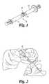
- FIG. 1is a perspective view of a mixing system for mixing an injectable biomaterial.
- FIG. 2is a pictorial view of the withdrawal of a cross-linker to be added to the biomaterial in the mixing system shown in FIG. 1 .
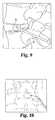
- FIGS. 3-5are diagrammatic view of surgical approaches to the intervertebral disc.
- FIG. 6is a pictorial view of a trial balloon assembly for use in a method of one embodiment of the present invention.
- FIG. 7is a pictorial representation of the use of the trial balloon shown in FIG. 6 in accordance with one aspect of the invention.
- FIG. 8is a pictorial view of a distraction balloon for use in a further aspect of the present invention.
- FIG. 9is a pictorial representation of the distraction balloon of FIG. 8 shown in situ.
- FIG. 10is a fluoroscopic view of a distraction balloon in situ.
- FIG. 11is a pictorial view of the injection of the cross-linker into the biomaterial mixing system.
- FIG. 12is a pictorial view of the step of mixing the biomaterial within the mixing system.
- FIG. 13is a pictorial representation of a vented injection needle assembly in accordance with one aspect of the present invention.
- FIG. 14is a fluoroscopic view of the vented injection needle assembly of FIG. 13 shown in situ.
- FIG. 15is a front perspective enlarged view of the vented injection needle in accordance with one embodiment of the invention.
- FIG. 16is an enlarged pictorial view of the vented injection needle depicted in FIG. 15 shown in situ.
- FIG. 17is an enlarged pictorial view of the distraction balloon shown in FIG. 9 .
- FIG. 18is an enlarged perspective view of a seal in accordance with a further embodiment of the invention.
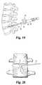
- FIG. 19is a lateral pictorial view of the spine with an injection assembly positioned to introduce a curable biomaterial into an affected disc in a percutaneous procedure.
- FIG. 20is an enlarged view of the disc shown in FIG. 19 with the injection needle and docking cannula of the injection assembly positioned within the disc annulus.
- FIG. 21is an enlarged view of a disc with a docking cannula according to a further embodiment with the injection needle extending therethrough into the disc space.
- FIG. 22is an enlarged cross-sectional view of the docking cannula and injection needle depicted in FIG. 21 .
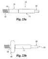
- FIGS. 23 a - bare side views of a docking cannula according to a further embodiment of the invention that includes an expandable flange, shown with the flange in its non-expanded and expanded positions.
- adjacent vertebral bodiesare distracted (by a non compliant balloon) at a predetermined pressure, such as at 200 psi (13 atmospheres).
- a predetermined pressuresuch as at 200 psi (13 atmospheres).
- the balloon (and thereby the distraction device)is then removed allowing the distracted vertebral bodies to remain distracted due to the natural stretching of the surrounding ligaments.
- the distraction with the balloon under pressureis held for a period of time sufficient to stretch the ligaments and to cause the distraction to be maintained even after the balloon is removed.
- This period of timewill vary between patients; however, in certain procedures a period of about 20-30 seconds has been sufficient, while in other cases the period may be several minutes. While there may be some slight contraction of the ligaments initially, the vertebral bodies will remain spaced apart at a substantially desired spacing for some time to then enable introduction of biomaterial into the distracted disc space.
- the biomaterialis sealably introduced under pressure that is not as high as used for the distraction step but that is sufficient so that the biomaterial will completely fill the space (or the partial space in a partial discectomy). Moreover, the injection pressure for the biomaterial is sufficient to recover any small amount of contraction that may occur when the balloon is removed. In accordance with one feature of the invention, the injection of the biomaterial occurs under low pressure. This pressure is nominally less than 100 psi, and in specific embodiments is in the range of 25-40 psi. A vent is used to exhaust the disc space and allow body fluid and/or air as well as biomaterial to seep out when the space is filled. Seepage of biomaterial indicates a complete fill of the disc space.
- the low pressure on the biomaterialis held until the biomaterial is cured. This cure time is material dependent, but often falls in the range of about five minutes. Maintaining the pressure until curing also maintains the distracted disc space under hydrostatic pressure. Even under the low pressure, a seal must be provided around the opening in the annulus through which biomaterial is introduced.
- the seal in one arrangementis disposed on the material injection tube and is applied against the exterior surface of the annulus adjacent the opening.
- a surgical techniquefor the use of injectable disc nucleus (IDN) as a replacement for or the augmentation of the natural nucleus pulposus.
- the IDNis preferably a curable biocompatible polymer with properties that emulate those of the natural human disc.
- a suitable IDN materialis disclosed in U.S. Pat. Nos. 6,423,333; 6,033,654; and 5,817,303, which issued to Protein Polymer Technologies, Inc. The disclosures or these patents are incorporated herein by reference. These patents disclose a proteinaceous curable polymer that has physical properties close to those of the human disc nucleus pulposus and that includes certain adhesive properties that allow the polymer to adhere to the disc annulus and any remaining disc nucleus pulposus.
- a mixing system 10is provided for mixing the constituents of the IDN material, as shown in FIG. 1 .
- the mixing system 10may be constructed as disclosed in co-pending, commonly assigned patent application Ser. No. 10/803,214, entitled “Systems and Methods for Mixing Fluids”. The entire disclosure of this application is incorporated herein by reference, and particularly the discussion of the embodiment shown in FIGS. 3-9 in that application.
- the mixing system 10is prepared prior to the start of surgery by loading the assembly with four mL of a polymer constituent. This volume is mixed with a cross-linker constituent.
- the volumeis mixed with 34 ⁇ 1 ⁇ L of crosslinker drawn from a sterile vial 12 into a 100 ⁇ L syringe 14 , purged of air, as shown in FIG. 2 .
- the syringeis placed on the sterile table until it is needed for the mixing and injection step.
- the biomaterialis an IDN
- access to the intradiscal spaceis required. While many surgical approaches may be used, in one specific embodiment, the surgeon will use an extraforaminal mini-open approach to the disc. This may be either by a lateral retroperitoneal approach ( FIG. 3 ) or a paramedian approach ( FIG. 4 ) through the paraspinal muscles of the back. Access to the nucleus is gained through an extraforaminal annulotomy, so as to not expose the spinal canal or foramen to any undue risk. The annulus is identified and a minimal annulotomy is performed to gain access to the intradiscal space. If necessary, a cruciate annulotomy of up to 5 mm ⁇ 5 mm may be used.
- the annulotomyshould be oriented obliquely with one cut oriented with the outer fibers of the annulus, as shown in FIG. 5 .
- the nucleus pulposusis then partially or completely removed using known techniques, such as using pituitary rongeurs and/or curettes. Alternatively, a mechanical method such as endoscopic shaving, hydraulic or radiofrequency (RF) technology may be used.
- the nucleotomyshould be fully irrigated once all loose fragments have been manually removed.
- the prepared nuclear cavityshould be visualized prior to proceeding using a compliant trial balloon assembly 20 , as depicted in FIG. 6 .
- the balloon 22is assembled to the inflation syringe 24 and primed with an inflation medium
- the balloonis inserted through the annulotomy until it stops against the far border of the nucleotomy space.
- the inflation mediumis a fluid contrast medium that can be visualized under fluoroscopy. Injection of contrast media into the balloon and inflation under light pressure will allow the surgeon to judge the location and size of the space ( FIGS. 7 and 17 ).
- the disc spacecan be visualized and the inflated size of the trial balloon measured to determine the distracted size of the disc space.
- An endoscopic cameramay also be used to inspect the interior of the nucleotomy space, if desired by the surgeon.
- the ballooncan be removed and the nucleotomy continued. This iterative process may be repeated until the surgeon is satisfied with the size and location of the nucleotomy.
- the final volume of contrast media injected into the balloonmay then be used to estimate the volume of the nucleotomy and determine the amount of IDN that will be needed to fill the space.
- the next step of the present inventioninvolves distracting the space.
- distraction of the discis accomplished using a spherical balloon 30 , such as a 15 mm diameter spherical balloon.
- the balloonis made of a non-compliant material and is adapted to provide a distraction force against the endplates of the disc.
- the balloon 30is able to be pressurized to approximately 13 atmospheres (200 psi). It is inflated using an inflation syringe 32 attached to the Luer fitting 34 on the catheter 36 of the balloon, as shown in FIG. 8 .
- Pressure feedbackis preferably obtained through tactile feel as the handle 35 is depressed, and/or through a pressure gage 38 mounted on the body of the inflation syringe.
- the balloonWhen the syringe and balloon are primed with contrast media, the balloon is inserted into the disc space until it stops against the far border of the nucleotomy, as shown in FIG. 9 , but is preferably positioned in the center of the disc space.
- the balloonis gradually inflated until it contacts the endplates and ultimately pushes apart the endplates to achieve the desired amount of distraction ( FIG. 10 ).
- the surgeoncan ensure that no loading of the annulus occurs and that the distraction force is applies solely to the endplates. Care should be taken to ensure the pressure rating of the balloon is not exceeded and that the endplates are not compromised by over-distraction.
- the balloonis deflated and removed from the disc.
- the trial balloon 22may be used again to evaluate the resulting final nucleotomy. If the trial balloon is re-used, the resulting fluid volume may again be used to estimate the volume of IDN needed to the fill the distracted space.
- distractionmay be obtained using the surgeon's preferred technique.
- Other distraction techniquessuch as laminar distraction, screw/pin distraction, patient positioning, and traction may be used.
- the distraction techniquemay need to be altered from patient to patient in order to address this matter.
- One techniquemay be preferred over others in certain instances due to patient bone quality and anatomy. If additional distraction is applied, the trial balloon 22 may be used again to provide an estimate of the requisite IDN fluid volume.
- the distraction of the disc spaceis maintained by the patient's anatomy, rather than by a distraction device maintained in the disc space. It has been found that if the distraction accomplished as described above is maintained for a certain length of time the spinal ligaments will stretch and retain their lengthened configuration for sufficient time to inject the IDN and allow it to cure. In a specific embodiment, maintaining the distraction for about 5 minutes was sufficient to cause the surrounding ligaments to maintain the distraction long enough to complete the IDN injection and curing process.
- suctionis applied to the cavity formed by the removal of tissue during the nucleotomy.
- a surgical swabmay also be used to wick away excess moisture from the injection site. This will ensure that excess fluid does not interfere with the injection of the IDN material.
- the plungersare preferably cycled through 10 full cycles in 10 seconds ( FIG. 12 ).
- the surgeondisassembles the syringe 14 (no insert in the syringe) from the adapter 13 . From this point, the surgeon has a fixed amount of working time to perform the injection using the second syringe 16 .
- this working timeis about 80 seconds.
- An appropriate previously selected injection needleis connected to the tip of the syringe 16 and the needle is primed with the fully mixed biomaterial composition prior to introducing the needle to the injection site.
- the initial drops from the injection needlecan be ejected onto the surgical field and used as a qualitative gage of the working time of the IDN during the injection procedure.
- the injection needleis provided as part of an injection assembly 40 , as shown in FIG. 13 .
- the injection needle 42extends through a seal element 46 that is configured to provide an essentially fluid tight seal against the disc annulus A.
- a vent 44also extends through the seal 46 .
- the seal 46is shown in more detail in FIG. 15 .
- the seal 46includes a body 48 that is preferably formed of a resilient material that can be compressed slightly under manual pressure to conform to the irregular external surface of the disc.
- the body 48defines a sealing face 50 that bears against the disc annulus A ( FIG. 13 ) to form the fluid tight seal.
- the boss 52is preferably configured in accordance with the shape of the annulotomy cut into the annulus. As illustrated, the annulotomy is cruciate, so that boss 52 is also cruciate in shape. In particular, the boss 52 includes wings 53 that are sized to fit within corresponding legs of the cruciate cut into the annulus A. The leading edges 53 a of the wings 53 can be rounded, as shown in FIG. 15 , to facilitate placement of the boss 52 within the annulotomy.
- the vent 44provides an additional wing 57 for the boss 52 .
- the wing 57includes a channel 58 that integrates with the hollow vent 44 .
- the vent wing 57is co-extensive with the other wings 52 .
- the working end of the wing 57can project slightly farther into the disc space.
- the injection needle 42feeds to a channel 55 defined in the boss 52 to provide a pathway for the IDN into the disc cavity.
- the needleis introduced through the annulotomy, while carefully retracting the nerve root, until the plug seal 50 seats against the annulus, as depicted in FIGS. 13-14 .
- the needleis positioned so that the vent 44 is facing upward during the injection, as depicted in FIG. 16 .
- Pressureis applied to the seal 46 to ensure no IDN leaks out between the seal and annulus.
- this pressureis applied manually by the surgeon by simply pressing the needle catheter 42 toward the annulus. Since the IDN injection occurs at low pressures, the amount of force required to maintain a fluid-tight seal between the seal face 50 and the annulus is minimal.
- the injection assembly 40may be modified to incorporate various of the sealing techniques described in co-pending application Ser. No. 10/282,755, filed on Oct. 29, 2002 in the name of inventors Boyd et al., and assigned to the assignee of the present invention and application.
- This co-pending applicationentitled “Devices and Methods for the Restoration of a Spinal Disc”, was published on May 1, 2003, as Pub. No. US2003/0083641A1.
- the disclosure of this co-pending and commonly assigned patent application and publicationis incorporated herein by reference for all purposes, and specifically the disclosure of the sealing and venting techniques illustrated in FIGS. 11-14 thereof.
- the IDNis injected into the space until IDN is seen flowing into or out of the vent tube.
- the vent tube 44is clear so that the presence of IDN fluid within the vent can be immediately detected. At this point, the injection is stopped and the needle is held in place until the IDN takes its initial set. A microscope or loupe may be used to visualize the injection process.
- the IDNis allowed to substantially completely cure before the injection needle assembly 40 is removed and the surgical site is closed.
- the cure perioddepends upon the particular IDN material. For the specific proteinaceous polymer discussed above, the cure period is a minimum of about five minutes. If IDN material is left within the annulotomy or external to the disc, it is preferably removed using rongeurs after the material has taken its initial set. Suction may also be used around the periphery of the annulotomy to remove cured material.
- the volume of IDN injected into the siteis preferably recorded from the graduations on the syringe 16 .
- the injection volumewill be the difference between the pre-and post-injection graduation readings.
- the woundis closed and dressed using the surgeon's preferred technique.
- the IDNis injected under low pressure, which at a minimum means enough pressure so that the IDN will fill all the space left by the excised nucleus material.
- the pressureshould be sufficient so that the intradiscal cavity can be filled in an acceptable amount of time, which is determined primarily by the cure rate for the IDN.
- the working time for the IDNi.e., the time from complete mixing of the constituents until the IDN has cured or hardened too much to flow
- the pressure exerted through the syringeshould be sufficient to completely fill the intradiscal cavity in about on minute. Manual operation of the syringe is preferred, but it is contemplated that other forms of pressurized injection of the IDN into the disc space is contemplated.
- the seal 46is formed of a resilient and deformable material so that it can be compressed against the annulus A to form a fluid tight seal.
- the seal 40is formed of SILASTIC® or a similar elastomeric material.
- the seal 46 in the illustrated embodimentis cylindrical with a circular sealing face 50 ; however, other configurations are contemplated provided they can adequately conform to the outer surface of the disc annulus.
- the vent 44can simply constitute a vent opening in the seal 46 .
- the vent tube 44is preferred because it carries the vented fluid away from the surgical site and can bring the discharge opening within clear view of the surgeon.
- the seal 46can be separate from the injection needle 42 and vent tube 44 .
- the channels 55 and 57can extend through the body 48 of the seal 46 . Catheters for the injection needle and vent can extend into the appropriate channel, preferably with a press-fit or fluid-tight engagement.
- the cruciform boss 52can be in the form of a duck-bill valve, as shown in FIG. 18 .
- the seal 60includes a valve boss 62 in the form of a cruciform duckbill valve.
- Each wing 63 of the boss 62includes a slit passageway 65 that expands under fluid pressure.
- the duckbill valve wings 63expand to allow the fluid to flow into the disc space.
- this expansion of the valve boss 62enhances the seal between the cruciate boss and the annulotomy.
- DDDdegenerative disc disease
- the annulusis typically relatively intact so that a minimal annulotomy is required to gain access to the intradiscal space. It is preferred that the opening is as small as feasible to minimize damage to the annulus.
- accesscan be via a K-wire over which a dilator, or a series of dilators, is passed.
- the nucleus pulposusmay be significantly under-hydrated or may contain significant fissures throughout the nucleus material, producing significant patient pain and giving rise to the need for a total or substantially total discectomy.
- the surgeonmay also chose to perform an intraoperative step of determining the integrity of the annulus, to confirm that the annulus is competent to withstand the distraction and IDN injection pressures.
- a saline solutionmay be injected into the intradiscal space through the annulotomy opening.
- a saline solutionis preferred since it is relatively easy to aspirate for removal from the intradiscal space.
- suitable solutionsmay also be used.
- the saline solutionmay be injected through a vented needle, in design and construction similar to the needle 40 shown in FIGS. 13-15 .
- this stepevaluates the integrity of the disc annulus—i.e., detects whether fissures or rents may be present in the annulus. This detection may be by tactful feel and/or by observation of leakage only at the injection needle site.
- the injected saline solutionmay be used to estimate the volume of the disc space to be filled with IDN material.
- a trial balloonsuch as the trial balloon 22 described above, may be used to ascertain the volume of the intradiscal space to be filled.
- suctionis applied to aspirate the nuclear cavity and a surgical swab may be used to wick away excess moisture that may interfere with the injection of the IDN material.
- the surgeonmay use the distraction balloon as illustrated in FIGS. 8-10 to apply a distraction force within the intradiscal space to distract the opposing vertebral bodies on either side of the intradiscal space, further separating apart such vertebral bodies.
- a subsequent saline testmay be conducted to further verify the integrity of the annulus.
- the IDNmay then be sealably injected under pressure using the vented needle 40 as described hereinabove.
- Such injection of IDNis preferred to be at a pressure that is not greater than the pressure under which the saline solution is injected and is typically on the order of 25-40 psi. While the saline solution has been described as preferably being injected with a vented needle such as described herein, it should be appreciated that a needle without a vent, but with a sealing element, could also be used in the practice of the annulus integrity test.
- the methods and devices of the present inventionare also contemplated for use in performing other open surgical procedures, such as an adjunct to microdiscectomy (AMD) procedure.
- AMDadjunct to microdiscectomy
- An AMD procedureis indicated where a total discectomy is not required, or more particularly where only a partial discectomy is necessary to restore normal or near normal function to the affected disc.
- the affected dischas a herniation or tear in the disc annulus. Access to the intradiscal space is thus available through the tear in the annulus.
- the injectable curable polymer constituentsPrior to the start of the surgery, the injectable curable polymer constituents are pre-loaded into the mixing syringe assembly, as described above, and left on the sterile instrument table until the appropriate time for injection of the IDN material.
- the surgeonuses a traditional open or microdiscectomy technique of preference for access to the disc herniation site.
- the patientwill be placed on a laminectomy frame in the prone position with the spine flexed to aid intraoperative exposure.
- the ligamentum flavum and laminar edgeare identified.
- a hemilaminectomy/medial facetectomymay be performed as necessary, with the aid of lateral fluoroscopy. Exposure of the hernia proceeds in a known manner, taking care to protect the dura and nerve root.
- the epidural spaceis explored to ensure that all disc fragments have been identified.
- annulotomymay be performed as described above.
- the herniated disc tissueis then removed according to known techniques, such as using pituitary rongeurs and/or curettes. Laminar distraction and/or flexion of the hips can be used to aid in exposure of the hernia site.
- distraction of the affected discmay be desired to improve the stability of the disc. This distraction may be accomplished using any of the techniques described above. If sufficient disc tissue has been removed around the herniation site, the distraction balloon may be used, provided that the balloon is removed once the desired distraction has been achieved.
- This balloon distractionmay also be supplemented in a two stage distraction technique described as follows. After a total or partial nucleotomy has been performed, in the first stage, a distraction balloon, such as the balloon 30 described above, is inserted into the intradiscal space. The balloon is then inflated to gain distraction of the anterior column of the disc space.
- a distraction balloonsuch as the balloon 30 described above
- a secondary distraction instrumentis introduced to act on any posterior bony structures at the particular intervertebral level in accordance with known surgical techniques.
- the secondary instrumentis used to obtain distraction of the posterior column at an appropriate amount decided by the surgeon.
- the nature and amount of this second stage distractionmay increase the overall amount of distraction of the total space, change the lordotic angle at the intervertebral level or cause no appreciable increase in the overall distraction of the space.
- the first stage distraction balloonis removed, while the secondary instrument remains in place to prevent any loss of distraction that may occur.
- the IDNmay be injected as described above.
- One benefit of this two-stage distraction techniqueis that the IDN material need not be injected under pressure in order to regain any distraction loss that may occur with the single stage distraction approaches discussed above. This benefit makes this two-stage approach particularly well suited for microdiscectomy in herniated nucleus pulposus cases in which the size of the opening or tear in the annulus can be widely variable. In these cases, sealing of the annular opening may be problematic, which ultimately makes pressurization of the IDN injection difficult.
- the secondary distraction instrumentis preferably a laminar or interspinous instrument.
- a laminar distractorapplies distraction force across the superior and inferior laminar arches, while the interspinous instrument applies force against the superior and inferior spinous processes.
- the secondary instrumentdoes not interfere with the removal of the first stage distraction balloon or the injection of the IDN material into the distracted space.
- a saline solution as described above with respect to the DDD proceduremay be injected through a vented needle into the intradiscal space to check the integrity of the annulus and to determine that there are no other leakage paths, as well as to estimate the volume of the intradiscal space to be filled. While this annulus integrity test is described as being conducted after distraction, it may also be done after removal of nucleus and prior to distraction.
- the surgeonmixes the IDN constituents, as described above, to prepare the IDN material for injection.
- An injection needlewhich is not required to be a vented, sealed needle, is introduced through the opening in the annulus until the needle tip reaches the far side of the cavity.
- the needleis preferably angled side-to-side and gradually withdrawn toward the annulus to ensure a complete fill of the space.
- the injectionis stopped and the needle is removed from the site.
- a vented needle 40 with a seal 46may be used, such as where the rent through the annulus is relatively small and not too irregular.
- the injectionis stopped when the IDN material is seen at the vent. It is contemplated that the IDN material will be injected under pressure, typically on the order of 25-40 psi, to ensure complete fill of the cavity, with the seal 46 of the vented needle 40 being pressed against the annulus during IDN injection.
- the present inventionalso contemplates a procedure for percutaneous direct injection of a curable biomaterial for treatment of degenerative disc disease.
- treatment for DDDis indicated where the disc annulus is generally intact, but the nucleus pulposus has been compromised, either by dehydration or the creation of fissures and the patient suffers from significant pain.
- some or all of the nucleusis removed to create an intradiscal space for injection of curable biomaterial.
- the defective or degenerated nucleusis not removed, but is instead augmented by a curable biomaterial or IDN material in a percutaneous procedure.
- a percutaneous procedureas intended herein, access to the spinal disc is achieved simply by introduction of a relatively small and sharp cannulated device, which may include a needle, through the skin and body tissue down to the surgical site under fluoroscopy or by using other conventional surgical navigation techniques. No incision is made nor is any body tissue retracted. Further, injection is continued by insertion of the cannulated device through the annulus into the nucleus pulposus, preferably without additional dilators and without removing any of the annulus tissue.
- the percutaneous procedure of the present inventionprovides a minimally invasive approach to treating DDD conditions.
- a first step of the procedureis preferably to obtain a pre-operative discogram.
- the discogramwill verify whether the annulus has sufficient integrity and competency to contain the injected nucleus augmentation. Ordinarily, the discogram will be performed two or three days prior to the comprehensive surgery.
- the pressure of the injected IDNis preferably at least as high as 100 psi and potentially as high as 200 psi so as to achieve distraction of the opposed vertebral bodies and increased disc height, desirably approaching normal anatomical conditions, upon injection of the IDN.
- the patientmay be given an epidural injection and an inflation syringe is used to inject a contrast solution directly into the disc.
- the inflation syringe 32 shown in FIG. 8may be used to introduce the pressurized contrast medium.
- the inflation syringe 36is modified to eliminate the balloon 30 mounted to the end of the catheter 36 , leaving the lumen of the catheter open for the contrast medium to flow through into the disc.
- the pressure gage 38may be used to verify the fluid pressure as the contrast agent is manually injected into the disc.
- the injection pressure for the contrast mediumis established by correlating its viscosity relative to the viscosity of the IDN material to be injected.
- the injection pressure for the IDNshould not be greater than the pressure of the injected contrast medium in the discogram.
- the contrast mediumis injected to approximately 160 psi. If the contrast medium has a lesser viscosity than the IDN, the injection pressure of the injected contrast medium may be decreased accordingly, so as to lessen the pain the patient may experience. If leakage is observed under fluoroscopy, use of the direct injection of IDN may be contraindicated and alternative treatments may be sought, one of which is described hereinbelow.
- the discogram procedureis conducted in accordance with conventional techniques as shown and described, for example, in U.S. Pat. No. 6,370,420, which is incorporated herein by reference.
- the contrast medium used in the discogramis fluid it is typically viscous, approximating the viscosity of the pre-cured IDN material.
- ithas a contrast agent that allows it to be visualized under fluoroscopy or other imaging techniques, permitting a visual observation of any leakage paths or fissures in the disc annulus prior to surgery.
- a discogramis commonly done several days prior to surgery so as to allow the contrast medium to dissipate and be absorbed into body tissue. However, an intraoperative discogram may also be considered.
- a saline solution as described hereinabovemay be considered. While a saline solution may be easier to remove than contrast medium, there is not sufficient contrast agent for fluoroscopic visualization or like imaging. Leaks may be detected manually, however, by tactile sensing by the surgeon, especially if upon injection of the saline solution pressure fails to build and stop, with injection of saline injection continuing. As such, a saline solution test may be performed intra-operatively as a final annulus integrity test as well as for determining the approximate volume of IDN material to inject.
- the IDN materialis prepared in the same manner described above, with the loaded mixing assembly and crosslinker syringes made available on a sterile instrument table until the appropriate time for injection of the IDN material.
- the injection assembly 70 shown in FIGS. 19-20is used to accomplish the injection step.
- the assembly 70includes a sharp cannulated device, such as a thin-walled docking cannula 72 with an integral mating hub 76 .
- the cannula 72has an relatively smooth outer surface and substantially constant outer and inner diameters along its length.
- An injection needle 74( FIG. 20 ) is slidably disposed within the docking cannula in a relatively close dimensional fit.
- the needle 74is integral with a hub 78 that may be configured to mate with the hub 76 of the cannula.
- a stopcock valve 80is fluidly connected to the hub 78 , and the injection syringe 82 is configured to engage the stopcock valve in any known manner effective to create a fluid tight connection.
- the injection syringe 82may be one of the syringes 14 , 16 of the mixing system illustrated in FIG. 1 .
- the patientis preferably placed in a prone position on an appropriate conventional Andrews frame or equivalent table, in the proper lordotic posture with the hips flexed to aid in the exposure of the posterior disc.
- the docking cannula 72is introduced to the disc in an extraforaminal location using a typical posterolateral discography approach.
- a guide styletmay extend through and be disposed in the cannula to assist in passing the cannula through the body tissue to the disc annulus A.
- the tip of the docking cannula 72is preferably confirmed, via fluoroscopy, to reside within the disc annulus, as depicted in FIG. 20 .
- the styletis removed once the docking of the cannula 72 is achieved.
- the tip of the docking cannulabreak through the annulus into the nucleus pulposus to ensure injection of the IDN material into the nuclear space and not into the annulus.
- the docking cannula 72will be engaged in the annulus and the hub 76 supported by the soft tissue between the disc and the entry point in the patient's back.
- the docking cannulais therefor sized for percutaneous introduction, while sufficiently large to accommodate an injection needle capable of injecting the IDN material.
- the docking cannulamay be a 16-20 hypodermic gage cannula.
- the cannulahas a length from the tip 73 to the hub 76 that is sufficient to allow the hub to sit outside the body.
- the docking cannula 72has a length of about 100 mm.
- the docking cannula 72itself may be configured to puncture the disc annulus, such as by a sharpened edge at the tip 73 of the cannula.
- the injection needle 74is sized for a close running fit within the docking cannula 72 .
- the injection needleis no more than two gages smaller than the docking cannula.
- the injection needlemay be 18-22 hypodermic gage corresponding to the 16-20 hypodermic gage cannula dimension.
- the IDN materialmay be the proteinaceous polymer that is the subject of the Protein Polymer Technology patents discussed above.
- the proteinaceous polymer in those patentsis described as having a lap shear tensile strength that within 30 minutes, usually within 15 minutes, more usually within 5 minutes, will be at least 100, preferably at least about 250, more preferably at least about 300, usually not exceeding about 4000, more usually not exceeding about 3000 g/cm 2 .
- This polymeris particularly well-suited for the percutaneous DDD procedure because as a result of its strong adhesive properties the polymer adheres to the existing nucleus pulposus and disc annulus.
- the IDN materialis injected under pressure into the nucleus pulposus to fill all voids, interstices and fissures that may exist in the existing nucleus.
- the polymercures in situ, it adheres to the existing natural disc material for essentially seamless integration with the existing disc nucleus, thereby substantially restoring the normal disc function.
- the IDNis injected directly into the nucleus within the disc space without any balloon or other physical barrier, there is greater potential for transporting nutrients to the cells and vertebral endplates surrounding it.
- the syringeis mated with the stopcock valve 80 of the injection needle hub 78 .
- the injection needleis then fed into the docking cannula 72 and into the nucleus pulposus and extended approximately to the center of the disc.
- the position of the needle tipis preferably confirmed via fluoroscopic imaging.
- the entire IDN injection processshould be completed fairly rapidly before the IDN material cures to a viscosity that will prevent full introduction of the IDN into the entire disc nucleus. In the specific embodiment using the polymer material discussed above, the surgeon must complete the injection within about 80 seconds after the IDN material has been fully mixed. Proper placement of the docking cannula 72 and the mating fit between the cannula hub 76 and the injection needle hub 78 can ensure that the needle tip is positioned substantially at the center of the disc, so that the fluoroscopic verification can be completed very quickly.
- the syringe 82may be manipulated to inject the IDN material through the needle 74 and into the disc space. Again, given the curing time constraints, the injection must proceed smoothly but rapidly so that all of the IDN material is injected into the disc space under pressure.
- the IDN materialis injected at a pressure in the range of about 100-160 psi, which is considered sufficient to achieve some distraction of the disc to account for some disc compression that may be associated with the DDD condition. This will provide increased stability to the disc, thus treating pain associated with DDD conditions. Since the present procedure is percutaneous, no initial pre-distraction of the disc space is accomplished beyond the amount of distraction that can be obtained by proper positioning of the patient on the Andrews frame.
- the injection pressuremay be estimated by the amount of manual pressure that can be achieved with the injection syringe 82 .
- a pressure gagemay be mounted to the needle hub 78 or stopcock valve 80 to provide a visual reading of the injection pressure. It is understood that the pressurized IDN material will seek to fill all voids and fissures in the disc nucleus pulposus, but will be contained by the disc annulus.
- the stopcock valve 80is closed to maintain the fluid pressure.
- the injection assembly 70is preferably held in place during the minimum cure time, which is about five minutes in the specific embodiment.
- the injection needleis removed.
- the natural disc and augmenting IDN materialwill collapse to fill the minimal channel left by removal of the injection needle 74 .
- the quick curing of the material, coupled with its natural adherent propertiesallow the IDN to substantially fully seal the entry point into the disc nucleus.
- the percutaneous nature of the procedureallows the wall of the disc annulus to collapse around the minimal channel left after the docking cannula 72 has been removed from the disc.
- the injection needle 74may be gradually retracted as the IDN material continues to be injected. Careful and controlled movement of the syringe 82 is necessary to ensure that the injection needle is retracted only to the inner border of the disc annulus and maintained in that position during the initial cure period. With this practice, the entire disc space is substantially filled, under pressure, with the IDN material.
- injection assembly 70has been described herein as including the docking cannula 72 and a separate injection needle 74 , it should be understood that other injection alternatives are contemplated.
- the needle 74itself may be directly injected without use of the docking cannula 72 .
- a docking cannula 90may be provided that includes a threaded tip 92 .
- the threadsare configured to pierce the annulus as the docking cannula 90 is rotated.
- the hubmay be modified from the hub 76 of the cannula 72 to provide a gripping surface suitable for manual threading of the cannula 90 into the disc annulus.
- Such threaded cannula 90would provide a more positive anchoring of the cannula 90 to the annulus.
- a sealwould be provided between the threaded tip 92 and the wall of the annulus since the cannula 90 is threaded into the annulus without an annulotomy being performed.
- a threaded cannula 90would allow injection of curable biomaterial at pressures greater than 160 psi and potentially up to as high as 200 psi.
- a thin-walled retractable outer sheathmay be positioned over the threads during insertion, and withdrawn upon insertion as the threaded tip 92 nears the annulus wall.
- the needleitself may be used without an outer cannula, and in such a situation, the needle 74 may be provided with threads at its distal tip.
- a flange 95may be defined on the cannula, as depicted in phantom lines in FIG. 22 .
- This flange 95may act as a stop to control the amount of insertion of the threaded tip 92 into the disc annulus.
- the flangemay also assist in providing and maintaining a fluid-tight seal at the opening formed in the annulus.
- the flangemay also include a fitting, such as a Luer lock fitting, to mate with the hub 78 of the injection needle. In this case, the fitting is preferably sized so that the fitting is accessible outside the percutaneous wound in the patient.
- a flanged cannulamay have particular application in the open DDD and/or AMD surgical procedures described hereinabove.
- a threaded docking cannula 100depicted in FIGS. 23 a - b , includes an expandable flange 106 .
- the cannulaincludes a cannula body 102 terminating in threads 104 for engagement within the disc annulus, as with the embodiments described above.
- the expandable flange 106is interposed between a fixed collar 108 and a sleeve 110 that is slidably disposed about the cannula body 102 .
- the expandable flangeis configured to have an un-expanded condition 106 , as shown in FIG. 23 a and then to move to an expanded condition 106 ′, shown in FIG.
- the flange 106is formed of a resilient material that deforms when pressed by the sleeve but returns substantially to its un-expended condition ( FIG. 23 a ) when the pressure is removed. In its un-expanded condition, the flange 106 has a small enough outer profile or diameter to be used percutaneously.
- a discogramis described as pre-operatively testing integrity of the disc annulus to determine if the disc is competent for subsequent direct injection of biomaterial under relatively high pressures of about 100 psi or more. If the discogram is negative, such direct injection is typically contraindicated.
- the following dual injection proceduremay be considered as an alternative treatment in such situation, where the annulus is still relatively intact.
- a first suitable quantity of IDNis prepared as described above and injected into the nucleus pulposus using, for example, the injection needle assembly 70 illustrated in FIGS. 19-20 .
- the materialis injected at relatively low pressure, i.e., on the order of about 25-40 psi, sufficient to allow the material to flow through and fill any fissures in the nucleus pulposus, but without causing distraction.
- the IDN materialis allowed to cure as described above, thereby providing a seal interiorly of the annulus within the disc space.
- a second suitable quantity of IDNis prepared and injected through the same access as the first injection, again using, for example an injection needle assembly 70 .
- the second quantity of IDNis injected under relatively high pressure, on the order of at least 100 psi in order to substantially fill the disc space and distract the opposing vertebral bodies, the first cured quantity of IDN serving as a barrier to maintain the second pressured quantity of IDN with the disc space.
- kits of the components described hereinmay be provided to a surgeon in order to perform the surgical procedures described herein.
- a kitmay include, but not be limited to, a vented needle or needle assembly, a suitable quantity of IDN material or its constituent parts to be mixed, a mixer for mixing the constituent parts, and a suitable syringe.
Landscapes
- Health & Medical Sciences (AREA)
- Orthopedic Medicine & Surgery (AREA)
- Life Sciences & Earth Sciences (AREA)
- Engineering & Computer Science (AREA)
- Biomedical Technology (AREA)
- Public Health (AREA)
- Veterinary Medicine (AREA)
- Heart & Thoracic Surgery (AREA)
- Animal Behavior & Ethology (AREA)
- General Health & Medical Sciences (AREA)
- Transplantation (AREA)
- Surgery (AREA)
- Vascular Medicine (AREA)
- Oral & Maxillofacial Surgery (AREA)
- Physical Education & Sports Medicine (AREA)
- Nuclear Medicine, Radiotherapy & Molecular Imaging (AREA)
- Cardiology (AREA)
- Molecular Biology (AREA)
- Medical Informatics (AREA)
- Neurology (AREA)
- Anesthesiology (AREA)
- Hematology (AREA)
- Biophysics (AREA)
- Prostheses (AREA)
- Surgical Instruments (AREA)
Abstract
Description
Claims (17)
Priority Applications (2)
| Application Number | Priority Date | Filing Date | Title |
|---|---|---|---|
| US11/170,657US8337557B2 (en) | 2004-06-29 | 2005-06-29 | Apparatus and kit for injecting a curable biomaterial into an intervertebral space |
| US11/969,303US8690883B2 (en) | 2004-06-29 | 2008-01-04 | Articulating injection cannula and seal assembly |
Applications Claiming Priority (2)
| Application Number | Priority Date | Filing Date | Title |
|---|---|---|---|
| US58366504P | 2004-06-29 | 2004-06-29 | |
| US11/170,657US8337557B2 (en) | 2004-06-29 | 2005-06-29 | Apparatus and kit for injecting a curable biomaterial into an intervertebral space |
Related Child Applications (1)
| Application Number | Title | Priority Date | Filing Date |
|---|---|---|---|
| US11/170,588Continuation-In-PartUS7837733B2 (en) | 2004-06-29 | 2005-06-29 | Percutaneous methods for injecting a curable biomaterial into an intervertebral space |
Publications (2)
| Publication Number | Publication Date |
|---|---|
| US20060004326A1 US20060004326A1 (en) | 2006-01-05 |
| US8337557B2true US8337557B2 (en) | 2012-12-25 |
Family
ID=35783345
Family Applications (8)
| Application Number | Title | Priority Date | Filing Date |
|---|---|---|---|
| US11/170,577Active2026-11-13US7789913B2 (en) | 2004-06-29 | 2005-06-29 | Methods for injecting a curable biomaterial into an intervertebral space |
| US11/170,657Expired - Fee RelatedUS8337557B2 (en) | 2004-06-29 | 2005-06-29 | Apparatus and kit for injecting a curable biomaterial into an intervertebral space |
| US11/170,382Expired - Fee RelatedUS7556650B2 (en) | 2004-06-29 | 2005-06-29 | Methods for injecting a curable biomaterial into an intervertebral space |
| US11/170,588Expired - Fee RelatedUS7837733B2 (en) | 2004-06-29 | 2005-06-29 | Percutaneous methods for injecting a curable biomaterial into an intervertebral space |
| US11/170,010Expired - Fee RelatedUS7722579B2 (en) | 2004-06-29 | 2005-06-29 | Devices for injecting a curable biomaterial into a intervertebral space |
| US11/169,405Expired - Fee RelatedUS7740660B2 (en) | 2004-06-29 | 2005-06-29 | Methods for treating defects and injuries of an intervertebral disc |
| US11/836,511AbandonedUS20080045897A1 (en) | 2004-06-29 | 2007-08-09 | Devices for Injecting a Curable Biomaterial into an Intervertebral Space |
| US12/861,037Expired - Fee RelatedUS8444694B2 (en) | 2004-06-29 | 2010-08-23 | Methods for injecting a curable biomaterial into an intervertebral space |
Family Applications Before (1)
| Application Number | Title | Priority Date | Filing Date |
|---|---|---|---|
| US11/170,577Active2026-11-13US7789913B2 (en) | 2004-06-29 | 2005-06-29 | Methods for injecting a curable biomaterial into an intervertebral space |
Family Applications After (6)
| Application Number | Title | Priority Date | Filing Date |
|---|---|---|---|
| US11/170,382Expired - Fee RelatedUS7556650B2 (en) | 2004-06-29 | 2005-06-29 | Methods for injecting a curable biomaterial into an intervertebral space |
| US11/170,588Expired - Fee RelatedUS7837733B2 (en) | 2004-06-29 | 2005-06-29 | Percutaneous methods for injecting a curable biomaterial into an intervertebral space |
| US11/170,010Expired - Fee RelatedUS7722579B2 (en) | 2004-06-29 | 2005-06-29 | Devices for injecting a curable biomaterial into a intervertebral space |
| US11/169,405Expired - Fee RelatedUS7740660B2 (en) | 2004-06-29 | 2005-06-29 | Methods for treating defects and injuries of an intervertebral disc |
| US11/836,511AbandonedUS20080045897A1 (en) | 2004-06-29 | 2007-08-09 | Devices for Injecting a Curable Biomaterial into an Intervertebral Space |
| US12/861,037Expired - Fee RelatedUS8444694B2 (en) | 2004-06-29 | 2010-08-23 | Methods for injecting a curable biomaterial into an intervertebral space |
Country Status (5)
| Country | Link |
|---|---|
| US (8) | US7789913B2 (en) |
| EP (1) | EP1768617A4 (en) |
| JP (1) | JP2008504895A (en) |
| AU (1) | AU2005260592B2 (en) |
| WO (1) | WO2006004887A2 (en) |
Cited By (14)
| Publication number | Priority date | Publication date | Assignee | Title |
|---|---|---|---|---|
| US20100114069A1 (en)* | 2008-10-30 | 2010-05-06 | Warsaw Orthopedic, Inc. | Methods, Systems, and Devices for Treating Intervertebral Discs Including Intradiscal Fluid Evacuation |
| US20160228558A1 (en)* | 2003-05-13 | 2016-08-11 | DePuy Synthes Products, Inc. | Transdiscal administration of specific inhibitors of pro-inflammatory cytokines |
| US9433404B2 (en) | 2012-10-31 | 2016-09-06 | Suture Concepts Inc. | Method and apparatus for closing fissures in the annulus fibrosus |
| US9545321B2 (en) | 2013-03-14 | 2017-01-17 | Spinal Stabilization Technologies Llc | Prosthetic spinal disk nucleus |
| US9949734B2 (en) | 2012-10-31 | 2018-04-24 | Suture Concepts Inc. | Method and apparatus for closing a fissure in the annulus of an intervertebral disc, and/or for effecting other anatomical repairs and/or fixations |
| US10314714B2 (en) | 2014-11-04 | 2019-06-11 | Spinal Stabilization Technologies Llc | Percutaneous implantable nuclear prosthesis |
| US10575967B2 (en) | 2015-09-01 | 2020-03-03 | Spinal Stabilization Technologies Llc | Implantable nuclear prosthesis |
| US10786235B2 (en) | 2012-10-31 | 2020-09-29 | Anchor Innovation Medical, Inc. | Method and apparatus for closing a fissure in the annulus of an intervertebral disc, and/or for effecting other anatomical repairs and/or fixations |
| US11633287B2 (en) | 2014-11-04 | 2023-04-25 | Spinal Stabilization Technologies Llc | Percutaneous implantable nuclear prosthesis |
| US11744710B2 (en) | 2018-09-04 | 2023-09-05 | Spinal Stabilization Technologies Llc | Implantable nuclear prosthesis, kits, and related methods |
| US11771841B2 (en) | 2020-12-23 | 2023-10-03 | Tolmar International Limited | Systems and methods for mixing syringe valve assemblies |
| US11812939B2 (en) | 2017-05-15 | 2023-11-14 | Cornell University | Device and system for repairing intervertebral disc herniation and methods of use |
| USD1029245S1 (en) | 2022-06-22 | 2024-05-28 | Tolmar International Limited | Syringe connector |
| US12357727B2 (en) | 2019-01-07 | 2025-07-15 | Regeltec, Inc. | Hydrogels and method of making the same |
Families Citing this family (172)
| Publication number | Priority date | Publication date | Assignee | Title |
|---|---|---|---|---|
| EP1624832A4 (en) | 1999-08-18 | 2008-12-24 | Intrinsic Therapeutics Inc | Devices and method for augmenting a vertebral disc nucleus |
| US7972337B2 (en) | 2005-12-28 | 2011-07-05 | Intrinsic Therapeutics, Inc. | Devices and methods for bone anchoring |
| US7717961B2 (en) | 1999-08-18 | 2010-05-18 | Intrinsic Therapeutics, Inc. | Apparatus delivery in an intervertebral disc |
| US7998213B2 (en) | 1999-08-18 | 2011-08-16 | Intrinsic Therapeutics, Inc. | Intervertebral disc herniation repair |
| CA2425951C (en)* | 1999-08-18 | 2008-09-16 | Intrinsic Therapeutics, Inc. | Devices and method for nucleus pulposus augmentation and retention |
| US7094258B2 (en) | 1999-08-18 | 2006-08-22 | Intrinsic Therapeutics, Inc. | Methods of reinforcing an annulus fibrosis |
| US8323341B2 (en) | 2007-09-07 | 2012-12-04 | Intrinsic Therapeutics, Inc. | Impaction grafting for vertebral fusion |
| US6723335B1 (en)* | 2000-04-07 | 2004-04-20 | Jeffrey William Moehlenbruck | Methods and compositions for treating intervertebral disc degeneration |
| US20020026244A1 (en)* | 2000-08-30 | 2002-02-28 | Trieu Hai H. | Intervertebral disc nucleus implants and methods |
| CA2549320A1 (en)* | 2000-08-30 | 2002-03-07 | Sdgi Holdings, Inc. | Intervertebral disc nucleus implants and methods |
| US20030195630A1 (en)* | 2002-04-10 | 2003-10-16 | Ferree Bret A. | Disc augmentation using materials that expand in situ |
| US6793678B2 (en) | 2002-06-27 | 2004-09-21 | Depuy Acromed, Inc. | Prosthetic intervertebral motion disc having dampening |
| CA2735324A1 (en)* | 2002-11-05 | 2004-05-21 | Spineology, Inc. | A semi-biological intervertebral disc replacement system |
| AU2004208821B2 (en)* | 2003-01-31 | 2009-01-15 | Zimmer Orthobiologics Inc. | Hydrogel compositions comprising nucleus pulposus tissue |
| AU2004212942A1 (en) | 2003-02-14 | 2004-09-02 | Depuy Spine, Inc. | In-situ formed intervertebral fusion device |
| WO2005058207A1 (en) | 2003-12-11 | 2005-06-30 | Isto Technologies, Inc. | Particulate cartilage system |
| US8690883B2 (en)* | 2004-06-29 | 2014-04-08 | Spine Wave, Inc. | Articulating injection cannula and seal assembly |
| US8357147B2 (en)* | 2005-08-17 | 2013-01-22 | Spinal Restoration, Inc. | Method for repairing intervertebral discs |
| US9943734B2 (en) | 2004-11-08 | 2018-04-17 | Taylor Made Golf Company, Inc. | Golf club |
| CH697330B1 (en) | 2004-12-28 | 2008-08-29 | Synthes Gmbh | Intervertebral prosthesis. |
| KR20080002824A (en)* | 2005-03-29 | 2008-01-04 | 신세스 게엠바하 | Implantation method and apparatus for hydrogel hydrogel prosthesis |
| US7955339B2 (en)* | 2005-05-24 | 2011-06-07 | Kyphon Sarl | Low-compliance expandable medical device |
| US20120143341A1 (en)* | 2006-12-12 | 2012-06-07 | Arthrodisc, L.L.C. | Devices and methods for visual differentiation of intervertebral spaces |
| US7988735B2 (en)* | 2005-06-15 | 2011-08-02 | Matthew Yurek | Mechanical apparatus and method for delivering materials into the inter-vertebral body space for nucleus replacement |
| AU2006281991A1 (en)* | 2005-08-15 | 2007-02-22 | Spinecell Pty Ltd | A tissue prosthesis and a method of, and equipment for, forming a tissue prosthesis |
| US20070043118A1 (en)* | 2005-08-16 | 2007-02-22 | Discogen, Llc | Method of treating a subject suffering from degenerative disc disease using a nitric oxide synthase inhibitor |
| WO2008103781A2 (en)* | 2007-02-21 | 2008-08-28 | Benvenue Medical, Inc. | Devices for treating the spine |
| AU2006279558B2 (en) | 2005-08-16 | 2012-05-17 | Izi Medical Products, Llc | Spinal tissue distraction devices |
| US8366773B2 (en) | 2005-08-16 | 2013-02-05 | Benvenue Medical, Inc. | Apparatus and method for treating bone |
| WO2007025290A2 (en)* | 2005-08-26 | 2007-03-01 | Isto Technologies, Inc. | Implants and methods for repair, replacement and treatment of joint disease |
| US20070067034A1 (en)* | 2005-08-31 | 2007-03-22 | Chirico Paul E | Implantable devices and methods for treating micro-architecture deterioration of bone tissue |
| US8998923B2 (en)* | 2005-08-31 | 2015-04-07 | Spinealign Medical, Inc. | Threaded bone filling material plunger |
| US8197545B2 (en)* | 2005-10-27 | 2012-06-12 | Depuy Spine, Inc. | Nucleus augmentation delivery device and technique |
| USD669168S1 (en) | 2005-11-18 | 2012-10-16 | Carefusion 2200, Inc. | Vertebral augmentation needle |
| US8690884B2 (en) | 2005-11-18 | 2014-04-08 | Carefusion 2200, Inc. | Multistate-curvature device and method for delivering a curable material into bone |
| US7713273B2 (en)* | 2005-11-18 | 2010-05-11 | Carefusion 2200, Inc. | Device, system and method for delivering a curable material into bone |
| US7799035B2 (en)* | 2005-11-18 | 2010-09-21 | Carefusion 2200, Inc. | Device, system and method for delivering a curable material into bone |
| US20070191860A1 (en)* | 2006-01-30 | 2007-08-16 | Sdgi Holdings, Inc. | Intervertebral prosthetic disc inserter |
| WO2007090127A2 (en) | 2006-01-30 | 2007-08-09 | Surgica Corporation | Compressible intravascular embolization particles and related methods and delivery systems |
| ATE520427T1 (en)* | 2006-01-30 | 2011-09-15 | Biosphere Medical Inc | POROUS INTRAVASCULAR EMBOLIZATION PARTICLES AND METHOD FOR THE PRODUCTION THEREOF |
| US20070213641A1 (en)* | 2006-02-08 | 2007-09-13 | Sdgi Holdings, Inc. | Constrained balloon disc sizer |
| US8323290B2 (en)* | 2006-03-03 | 2012-12-04 | Biomet Manufacturing Corp. | Tensor for use in surgical navigation |
| US20070232905A1 (en)* | 2006-04-04 | 2007-10-04 | Francis Tom J | Unconstrained Balloon Sizer |
| US8118844B2 (en) | 2006-04-24 | 2012-02-21 | Warsaw Orthopedic, Inc. | Expandable device for insertion between anatomical structures and a procedure utilizing same |
| US20070270823A1 (en)* | 2006-04-28 | 2007-11-22 | Sdgi Holdings, Inc. | Multi-chamber expandable interspinous process brace |
| US8252031B2 (en) | 2006-04-28 | 2012-08-28 | Warsaw Orthopedic, Inc. | Molding device for an expandable interspinous process implant |
| US8147517B2 (en) | 2006-05-23 | 2012-04-03 | Warsaw Orthopedic, Inc. | Systems and methods for adjusting properties of a spinal implant |
| US20080021457A1 (en)* | 2006-07-05 | 2008-01-24 | Warsaw Orthopedic Inc. | Zygapophysial joint repair system |
| US20080021556A1 (en)* | 2006-07-21 | 2008-01-24 | Edie Jason A | Expandable vertebral implant and methods of use |
| US20080058931A1 (en)* | 2006-07-21 | 2008-03-06 | John White | Expandable vertebral implant and methods of use |
| MX2009002455A (en)* | 2006-09-07 | 2009-03-20 | Wyeth Corp | Bone cement mixing systems and related methods. |
| US8357168B2 (en)* | 2006-09-08 | 2013-01-22 | Spine Wave, Inc. | Modular injection needle and seal assembly |
| CN101883604A (en) | 2006-11-28 | 2010-11-10 | 康隆有限公司 | Tissue prosthesis insertion system and method |
| AU2007329469A1 (en)* | 2006-12-01 | 2008-06-12 | The Board Of Trustees Of The Leland Stanford Junior University | Devices and methods for accessing the epidural space |
| US11395626B2 (en) | 2006-12-07 | 2022-07-26 | DePuy Synthes Products, Inc. | Sensor for intervertebral fusion indicia |
| WO2008070863A2 (en) | 2006-12-07 | 2008-06-12 | Interventional Spine, Inc. | Intervertebral implant |
| US7875079B2 (en)* | 2006-12-14 | 2011-01-25 | Warsaw Orthopedic, Inc. | Vertebral implant containment device and methods of use |
| WO2008076330A1 (en)* | 2006-12-15 | 2008-06-26 | Soteira, Inc. | Drills and methods for vertebrostenting |
| US8163549B2 (en) | 2006-12-20 | 2012-04-24 | Zimmer Orthobiologics, Inc. | Method of obtaining viable small tissue particles and use for tissue repair |
| US20080154233A1 (en)* | 2006-12-20 | 2008-06-26 | Zimmer Orthobiologics, Inc. | Apparatus for delivering a biocompatible material to a surgical site and method of using same |
| US8840618B2 (en)* | 2007-01-12 | 2014-09-23 | Warsaw Orthopedic, Inc. | System and method for pressure mixing bone filling material |
| EP2124778B1 (en) | 2007-02-21 | 2019-09-25 | Benvenue Medical, Inc. | Devices for treating the spine |
| WO2008109566A1 (en)* | 2007-03-02 | 2008-09-12 | Spinealign Medical, Inc. | Fracture fixation system and method |
| US8206391B2 (en)* | 2007-03-07 | 2012-06-26 | Vertech, Inc. | Expandable blade device for stabilizing compression fractures |
| US20090012629A1 (en)* | 2007-04-12 | 2009-01-08 | Isto Technologies, Inc. | Compositions and methods for tissue repair |
| US8864801B2 (en) | 2007-04-30 | 2014-10-21 | Warsaw Orthopedic, Inc. | Method of deformity correction in a spine using injectable materials |
| US20090276048A1 (en)* | 2007-05-08 | 2009-11-05 | Chirico Paul E | Devices and method for bilateral support of a compression-fractured vertebral body |
| EP2155123A1 (en)* | 2007-05-14 | 2010-02-24 | Promethean Surgical Devices, Llc | Foam prosthesis for spinal disc |
| US8900307B2 (en) | 2007-06-26 | 2014-12-02 | DePuy Synthes Products, LLC | Highly lordosed fusion cage |
| US8052728B2 (en)* | 2007-07-31 | 2011-11-08 | Zimmer Spine, Inc. | Method for stabilizing a facet joint |
| CA2928681C (en)* | 2007-08-29 | 2018-03-27 | Etex Corporation | Bone cement mixing and delivery system and methods of use thereof |
| US20110196492A1 (en)* | 2007-09-07 | 2011-08-11 | Intrinsic Therapeutics, Inc. | Bone anchoring systems |
| US8758439B2 (en) | 2007-11-19 | 2014-06-24 | Linares Medical Devices, Llc | Spine support implant including inter vertebral insertable fluid ballastable insert and inter-vertebral web retaining harnesses |
| US20090131984A1 (en)* | 2007-11-19 | 2009-05-21 | Linares Miguel A | Spine support implant including inter vertebral insertable fluid ballastable insert and inter-vertebral web retaining harnesses |
| EP2237748B1 (en) | 2008-01-17 | 2012-09-05 | Synthes GmbH | An expandable intervertebral implant |
| US20090216260A1 (en)* | 2008-02-20 | 2009-08-27 | Souza Alison M | Interlocking handle |
| US8114136B2 (en) | 2008-03-18 | 2012-02-14 | Warsaw Orthopedic, Inc. | Implants and methods for inter-spinous process dynamic stabilization of a spinal motion segment |
| US8936641B2 (en) | 2008-04-05 | 2015-01-20 | DePuy Synthes Products, LLC | Expandable intervertebral implant |
| EP2285312A4 (en)* | 2008-05-01 | 2014-03-12 | Columna Pty Ltd | Systems methods and apparatuses for formation and insertion of tissue prostheses |
| US7976578B2 (en)* | 2008-06-04 | 2011-07-12 | James Marvel | Buffer for a human joint and method of arthroscopically inserting |
| WO2009155319A1 (en) | 2008-06-17 | 2009-12-23 | Soteira, Inc. | Devices and methods for fracture reduction |
| US8277506B2 (en) | 2008-06-24 | 2012-10-02 | Carefusion 2200, Inc. | Method and structure for stabilizing a vertebral body |
| US20100004745A1 (en)* | 2008-07-01 | 2010-01-07 | Doctors Research Group, Inc. | Fusing Bone |
| US20100168748A1 (en)* | 2008-07-16 | 2010-07-01 | Knopp Peter G | Morselizer |
| WO2010018447A1 (en)* | 2008-08-13 | 2010-02-18 | Del Corso, Andrea | Occlusion device for vascular surgery |
| US20110212179A1 (en)* | 2008-10-30 | 2011-09-01 | David Liu | Micro-spherical porous biocompatible scaffolds and methods and apparatus for fabricating same |
| WO2010078488A2 (en)* | 2008-12-31 | 2010-07-08 | Spinealign Medical, Inc. | Self-expanding bone stabilization devices |
| US20100174243A1 (en)* | 2009-01-05 | 2010-07-08 | Warsaw Orthopedic, Inc. | Apparatus for Delivery of Therapeutic Material to an Intervertebral Disc and Method of Use |
| US8535327B2 (en) | 2009-03-17 | 2013-09-17 | Benvenue Medical, Inc. | Delivery apparatus for use with implantable medical devices |
| WO2010111246A1 (en) | 2009-03-23 | 2010-09-30 | Soteira, Inc. | Devices and methods for vertebrostenting |
| US9526620B2 (en) | 2009-03-30 | 2016-12-27 | DePuy Synthes Products, Inc. | Zero profile spinal fusion cage |
| US20100256483A1 (en)* | 2009-04-03 | 2010-10-07 | Insite Medical Technologies, Inc. | Devices and methods for tissue navigation |
| US8377013B2 (en)* | 2009-08-05 | 2013-02-19 | The University Of Toledo | Needle for directional control of the injection of bone cement into a vertebral compression fracture |
| US8403988B2 (en) | 2009-09-11 | 2013-03-26 | Depuy Spine, Inc. | Minimally invasive intervertebral staple distraction devices |
| US9615933B2 (en)* | 2009-09-15 | 2017-04-11 | DePuy Synthes Products, Inc. | Expandable ring intervertebral fusion device |
| US9132207B2 (en)* | 2009-10-27 | 2015-09-15 | Spine Wave, Inc. | Radiopaque injectable nucleus hydrogel compositions |
| US8894658B2 (en) | 2009-11-10 | 2014-11-25 | Carefusion 2200, Inc. | Apparatus and method for stylet-guided vertebral augmentation |
| US8864768B2 (en) | 2009-11-20 | 2014-10-21 | Zimmer Knee Creations, Inc. | Coordinate mapping system for joint treatment |
| WO2011063260A1 (en) | 2009-11-20 | 2011-05-26 | Knee Creations, Llc | Bone-derived implantable devices for subchondral treatment of joint pain |
| US9259257B2 (en) | 2009-11-20 | 2016-02-16 | Zimmer Knee Creations, Inc. | Instruments for targeting a joint defect |
| WO2011063240A1 (en) | 2009-11-20 | 2011-05-26 | Knee Creations, Llc | Implantable devices for subchondral treatment of joint pain |
| JP2013511356A (en) | 2009-11-20 | 2013-04-04 | ニー・クリエイションズ・リミテッド・ライアビリティ・カンパニー | Device for variable angle approach to joints |
| EP2501303B1 (en) | 2009-11-20 | 2020-02-12 | Zimmer Knee Creations, Inc. | Navigation and positioning instruments for joint repair |
| US8951261B2 (en) | 2009-11-20 | 2015-02-10 | Zimmer Knee Creations, Inc. | Subchondral treatment of joint pain |
| US8821504B2 (en) | 2009-11-20 | 2014-09-02 | Zimmer Knee Creations, Inc. | Method for treating joint pain and associated instruments |
| US9393129B2 (en) | 2009-12-10 | 2016-07-19 | DePuy Synthes Products, Inc. | Bellows-like expandable interbody fusion cage |
| US9480511B2 (en) | 2009-12-17 | 2016-11-01 | Engage Medical Holdings, Llc | Blade fixation for ankle fusion and arthroplasty |
| US8317831B2 (en) | 2010-01-13 | 2012-11-27 | Kyphon Sarl | Interspinous process spacer diagnostic balloon catheter and methods of use |
| US8864711B2 (en)* | 2010-01-27 | 2014-10-21 | Warsaw Orthopedic, Inc. | Drug dispensing balloon for treating disc disease or pain |
| US8147526B2 (en) | 2010-02-26 | 2012-04-03 | Kyphon Sarl | Interspinous process spacer diagnostic parallel balloon catheter and methods of use |
| US8979860B2 (en) | 2010-06-24 | 2015-03-17 | DePuy Synthes Products. LLC | Enhanced cage insertion device |
| US9907560B2 (en) | 2010-06-24 | 2018-03-06 | DePuy Synthes Products, Inc. | Flexible vertebral body shavers |
| US8623091B2 (en) | 2010-06-29 | 2014-01-07 | DePuy Synthes Products, LLC | Distractible intervertebral implant |
| US9402732B2 (en) | 2010-10-11 | 2016-08-02 | DePuy Synthes Products, Inc. | Expandable interspinous process spacer implant |
| US8425611B2 (en)* | 2010-10-26 | 2013-04-23 | Warsaw Orthopedic, Inc. | Expandable orthopedic implant system and method |
| US9220535B2 (en)* | 2010-10-26 | 2015-12-29 | Christian Röbling | Process for introducing a stabilizing element into a vertebral column |
| EP2651341B1 (en) | 2010-12-16 | 2017-01-04 | Engage Medical Holdings, LLC | Arthroplasty systems and methods |
| US9358122B2 (en) | 2011-01-07 | 2016-06-07 | K2M, Inc. | Interbody spacer |
| US9265620B2 (en) | 2011-03-18 | 2016-02-23 | Raed M. Ali, M.D., Inc. | Devices and methods for transpedicular stabilization of the spine |
| EP2685921B1 (en) | 2011-03-18 | 2019-03-13 | Raed M. Ali, M.D., Inc. | Transpedicular access to intervertebral spaces and related spinal fusion systems and methods |
| US9700425B1 (en) | 2011-03-20 | 2017-07-11 | Nuvasive, Inc. | Vertebral body replacement and insertion methods |
| US9060878B2 (en) | 2011-03-28 | 2015-06-23 | Ray G. Oktavec | Percutaneous biologic delivery system |
| US9554840B2 (en)* | 2011-04-08 | 2017-01-31 | Kyphon SÀRL | Low cost low profile inflatable bone tamp |
| US8814873B2 (en) | 2011-06-24 | 2014-08-26 | Benvenue Medical, Inc. | Devices and methods for treating bone tissue |
| USD712025S1 (en)* | 2011-06-28 | 2014-08-26 | Daikyo Seiko, Ltd. | Syringe barrel |
| US20130109999A1 (en)* | 2011-10-31 | 2013-05-02 | Kimberly-Clerk, Inc. | Manometer for Use in Testing Spinal Region and Related Method |
| US9254130B2 (en) | 2011-11-01 | 2016-02-09 | Hyun Bae | Blade anchor systems for bone fusion |
| US9615856B2 (en) | 2011-11-01 | 2017-04-11 | Imds Llc | Sacroiliac fusion cage |
| US10238382B2 (en) | 2012-03-26 | 2019-03-26 | Engage Medical Holdings, Llc | Blade anchor for foot and ankle |
| US9307968B2 (en)* | 2012-06-15 | 2016-04-12 | The University Of Hong Kong | Materials and methods for filling biological cavities and preventing leakage of injected therapeutic agents |
| EP2877127B1 (en) | 2012-07-26 | 2019-08-21 | Synthes GmbH | Expandable implant |
| US20140067069A1 (en) | 2012-08-30 | 2014-03-06 | Interventional Spine, Inc. | Artificial disc |
| US20140178343A1 (en) | 2012-12-21 | 2014-06-26 | Jian Q. Yao | Supports and methods for promoting integration of cartilage tissue explants |
| US9387030B2 (en) | 2013-01-07 | 2016-07-12 | Kyphon SÀRL | Catheter with integrated cement delivery balloon |
| US9192420B2 (en) | 2013-01-24 | 2015-11-24 | Kyphon Sarl | Surgical system and methods of use |
| US9238125B2 (en) | 2013-01-31 | 2016-01-19 | Medtronic Xomed, Inc. | Inflation device for balloon sinus dilation |
| US9717601B2 (en) | 2013-02-28 | 2017-08-01 | DePuy Synthes Products, Inc. | Expandable intervertebral implant, system, kit and method |
| US9522070B2 (en) | 2013-03-07 | 2016-12-20 | Interventional Spine, Inc. | Intervertebral implant |
| US10687962B2 (en) | 2013-03-14 | 2020-06-23 | Raed M. Ali, M.D., Inc. | Interbody fusion devices, systems and methods |
| US10085783B2 (en) | 2013-03-14 | 2018-10-02 | Izi Medical Products, Llc | Devices and methods for treating bone tissue |
| US9861495B2 (en) | 2013-03-14 | 2018-01-09 | Raed M. Ali, M.D., Inc. | Lateral interbody fusion devices, systems and methods |
| KR101525733B1 (en)* | 2014-02-28 | 2015-06-03 | 가톨릭대학교 산학협력단 | Surgical kits for autologous collagen-induced chondrogenesis |
| CN106456215B (en) | 2014-04-28 | 2020-04-10 | 诺威适骨科专科公司 | External adjustment device for adjusting a medical implant |
| US9693882B2 (en) | 2014-06-03 | 2017-07-04 | DePuy Synthes Products, Inc. | Optical trial device |
| US9770577B2 (en) | 2014-09-15 | 2017-09-26 | Medtronic Xomed, Inc. | Pressure relief for a catheter balloon device |
| US11426290B2 (en) | 2015-03-06 | 2022-08-30 | DePuy Synthes Products, Inc. | Expandable intervertebral implant, system, kit and method |
| US10449055B2 (en) | 2015-04-23 | 2019-10-22 | Disc Fix L.L.C. | Systems and methods for treatment of intervertebral disc derangements |
| US9913727B2 (en) | 2015-07-02 | 2018-03-13 | Medos International Sarl | Expandable implant |
| US11039755B2 (en)* | 2015-12-03 | 2021-06-22 | Robert S. Katz | Methods and systems for diagnosing and treating fibromyalgia |
| US10285825B2 (en)* | 2016-04-07 | 2019-05-14 | Howmedica Osteonics Corp. | Surgical insertion instruments |
| EP3474784A2 (en) | 2016-06-28 | 2019-05-01 | Eit Emerging Implant Technologies GmbH | Expandable and angularly adjustable intervertebral cages with articulating joint |
| US11510788B2 (en) | 2016-06-28 | 2022-11-29 | Eit Emerging Implant Technologies Gmbh | Expandable, angularly adjustable intervertebral cages |
| US10390955B2 (en) | 2016-09-22 | 2019-08-27 | Engage Medical Holdings, Llc | Bone implants |
| US10537436B2 (en) | 2016-11-01 | 2020-01-21 | DePuy Synthes Products, Inc. | Curved expandable cage |
| US10888433B2 (en) | 2016-12-14 | 2021-01-12 | DePuy Synthes Products, Inc. | Intervertebral implant inserter and related methods |
| US11540928B2 (en) | 2017-03-03 | 2023-01-03 | Engage Uni Llc | Unicompartmental knee arthroplasty |
| US10456272B2 (en) | 2017-03-03 | 2019-10-29 | Engage Uni Llc | Unicompartmental knee arthroplasty |
| US10398563B2 (en) | 2017-05-08 | 2019-09-03 | Medos International Sarl | Expandable cage |
| US11344424B2 (en) | 2017-06-14 | 2022-05-31 | Medos International Sarl | Expandable intervertebral implant and related methods |
| US10940016B2 (en) | 2017-07-05 | 2021-03-09 | Medos International Sarl | Expandable intervertebral fusion cage |
| EP3456297B1 (en) | 2017-09-15 | 2023-10-04 | Howmedica Osteonics Corp. | Instruments for expandable interbody implants |
| US11446156B2 (en) | 2018-10-25 | 2022-09-20 | Medos International Sarl | Expandable intervertebral implant, inserter instrument, and related methods |
| US11690974B2 (en) | 2019-04-25 | 2023-07-04 | Warsaw Orthopedic, Inc. | Methods and devices for delivering therapeutic materials to the intervertebral disc |
| US11426286B2 (en) | 2020-03-06 | 2022-08-30 | Eit Emerging Implant Technologies Gmbh | Expandable intervertebral implant |
| US20220047846A1 (en)* | 2020-08-13 | 2022-02-17 | Covidien Lp | Rolling sleeve for an endoluminal shaft |
| US11103290B1 (en)* | 2021-01-25 | 2021-08-31 | Osteon Medical LLC | Kyphoplasty system and method |
| US11850160B2 (en) | 2021-03-26 | 2023-12-26 | Medos International Sarl | Expandable lordotic intervertebral fusion cage |
| US11752009B2 (en) | 2021-04-06 | 2023-09-12 | Medos International Sarl | Expandable intervertebral fusion cage |
| US20250127544A1 (en)* | 2021-10-27 | 2025-04-24 | Encapsulemed, Inc. | System and device for performing vertebral augmentation |
| US12090064B2 (en) | 2022-03-01 | 2024-09-17 | Medos International Sarl | Stabilization members for expandable intervertebral implants, and related systems and methods |
| KR102825366B1 (en)* | 2023-04-05 | 2025-06-26 | 울산대학교 산학협력단 | Cage for spinal surgery |
| US11903628B1 (en) | 2023-04-20 | 2024-02-20 | Osteon Medical LLC | Kyphoplasty system and method |
Citations (68)
| Publication number | Priority date | Publication date | Assignee | Title |
|---|---|---|---|---|
| US3893445A (en) | 1974-01-09 | 1975-07-08 | Becton Dickinson Co | Bone marrow biopsy instrument |
| US4142517A (en) | 1976-07-23 | 1979-03-06 | Contreras Guerrero De Stavropo | Apparatus for extracting bone marrow specimens |
| US4313434A (en) | 1980-10-17 | 1982-02-02 | David Segal | Fracture fixation |
| US4492576A (en) | 1982-06-15 | 1985-01-08 | Dragan William B | Dental syringe and method of packaging and dispensing a dental material |
| US4684363A (en) | 1984-10-31 | 1987-08-04 | American Hospital Supply Corporation | Rapidly inflatable balloon catheter and method |
| EP0277282A1 (en) | 1987-01-08 | 1988-08-10 | GebràDer Sulzer Aktiengesellschaft | Joint endoprosthesis |
| US4772287A (en) | 1987-08-20 | 1988-09-20 | Cedar Surgical, Inc. | Prosthetic disc and method of implanting |
| US4793351A (en) | 1987-06-15 | 1988-12-27 | Mansfield Scientific, Inc. | Multi-lumen balloon catheter |
| FR2639823A1 (en) | 1988-12-06 | 1990-06-08 | Garcia Alain | Replacement of the nucleus of the intervertebral disc by a polyurethane polymerised in situ |
| US4969888A (en) | 1989-02-09 | 1990-11-13 | Arie Scholten | Surgical protocol for fixation of osteoporotic bone using inflatable device |
| US5300035A (en) | 1991-10-24 | 1994-04-05 | Mectra Labs, Inc. | Threaded screw trocar with sealing mechanism |
| US5331975A (en) | 1990-03-02 | 1994-07-26 | Bonutti Peter M | Fluid operated retractors |
| US5344439A (en) | 1992-10-30 | 1994-09-06 | Medtronic, Inc. | Catheter with retractable anchor mechanism |
| US5380334A (en) | 1993-02-17 | 1995-01-10 | Smith & Nephew Dyonics, Inc. | Soft tissue anchors and systems for implantation |
| US5431676A (en) | 1993-03-05 | 1995-07-11 | Innerdyne Medical, Inc. | Trocar system having expandable port |
| US5454365A (en) | 1990-11-05 | 1995-10-03 | Bonutti; Peter M. | Mechanically expandable arthroscopic retractors |
| US5514153A (en) | 1990-03-02 | 1996-05-07 | General Surgical Innovations, Inc. | Method of dissecting tissue layers |
| US5549565A (en) | 1993-07-13 | 1996-08-27 | Symbiosis Corporation | Reusable surgical trocar with disposable valve assembly |
| US5562736A (en) | 1994-10-17 | 1996-10-08 | Raymedica, Inc. | Method for surgical implantation of a prosthetic spinal disc nucleus |
| US5667520A (en) | 1990-03-02 | 1997-09-16 | General Surgical Innovations, Inc. | Method of performing balloon dissection |
| US5720726A (en) | 1992-12-30 | 1998-02-24 | Medtronic, Inc. | Balloon catheter having retention enhancements on the balloon |
| US5752969A (en) | 1993-06-17 | 1998-05-19 | Sofamor S.N.C. | Instrument for the surgical treatment of an intervertebral disc by the anterior route |
| US5762629A (en) | 1991-10-30 | 1998-06-09 | Smith & Nephew, Inc. | Oval cannula assembly and method of use |
| US5810769A (en)* | 1994-02-25 | 1998-09-22 | Suddeutsche Feinmechanik Gmbh | Cannula for the subcutaneous deposition of an object |
| US5817303A (en) | 1995-05-05 | 1998-10-06 | Protein Polymer Technologies, Inc. | Bonding together tissue with adhesive containing polyfunctional crosslinking agent and protein polymer |
| US5827318A (en) | 1990-03-02 | 1998-10-27 | General Surgical Innovations, Inc. | Method of dissecting tissue layers |
| US5888220A (en) | 1994-05-06 | 1999-03-30 | Advanced Bio Surfaces, Inc. | Articulating joint repair |
| US5954739A (en) | 1990-03-02 | 1999-09-21 | General Surgical Innovations, Inc. | Method of dissecting tissue layers |
| US5968062A (en) | 1996-04-12 | 1999-10-19 | Surgical Dynamics, Inc. | Surgical cutting device removeably connected to a rotarty drive element |
| US6039761A (en) | 1997-02-12 | 2000-03-21 | Li Medical Technologies, Inc. | Intervertebral spacer and tool and method for emplacement thereof |
| US6083202A (en)* | 1999-10-14 | 2000-07-04 | Syntheon, Llc | Endoscopic needle injection device |
| US6135999A (en) | 1997-02-12 | 2000-10-24 | Oratec Internationals, Inc. | Concave probe for arthroscopic surgery |
| US6174311B1 (en) | 1998-10-28 | 2001-01-16 | Sdgi Holdings, Inc. | Interbody fusion grafts and instrumentation |
| US6187048B1 (en) | 1994-05-24 | 2001-02-13 | Surgical Dynamics, Inc. | Intervertebral disc implant |
| US6210397B1 (en) | 1999-01-13 | 2001-04-03 | A-Med Systems, Inc. | Sealing cannula device |
| US6224630B1 (en) | 1998-05-29 | 2001-05-01 | Advanced Bio Surfaces, Inc. | Implantable tissue repair device |
| US6245107B1 (en) | 1999-05-28 | 2001-06-12 | Bret A. Ferree | Methods and apparatus for treating disc herniation |
| US6248131B1 (en) | 1994-05-06 | 2001-06-19 | Advanced Bio Surfaces, Inc. | Articulating joint repair |
| US6264659B1 (en) | 1999-02-22 | 2001-07-24 | Anthony C. Ross | Method of treating an intervertebral disk |
| US6306177B1 (en) | 1994-05-06 | 2001-10-23 | Advanced Bio Surfaces, Inc. | Biomaterial system for in situ tissue repair |
| US6370420B1 (en) | 1998-11-17 | 2002-04-09 | Mark Kraft | System and method for objectively verifying an internal disc disruption |
| US6371990B1 (en) | 1999-10-08 | 2002-04-16 | Bret A. Ferree | Annulus fibrosis augmentation methods and apparatus |
| US20020045942A1 (en) | 2000-10-16 | 2002-04-18 | Ham Michael J. | Procedure for repairing damaged discs |
| US6402784B1 (en) | 1997-07-10 | 2002-06-11 | Aberdeen Orthopaedic Developments Limited | Intervertebral disc nucleus prosthesis |
| US6436143B1 (en) | 1999-02-22 | 2002-08-20 | Anthony C. Ross | Method and apparatus for treating intervertebral disks |
| US20020147497A1 (en)* | 2001-04-06 | 2002-10-10 | Integrated Vascular Systems, Inc. | Methods for treating spinal discs |
| US20030009227A1 (en) | 1999-08-18 | 2003-01-09 | Lambrecht Gregory H. | Methods of reinforcing an annulus fibrosis |
| US20030033017A1 (en) | 2001-06-29 | 2003-02-13 | The Regents Of The University Of California | Biodegradable/bioactive nucleus pulposus implant and method for treating degenerated intervertebral discs |
| US20030083642A1 (en)* | 2001-11-01 | 2003-05-01 | Boyd Lawrence M. | Devices and methods for the restoration of a spinal disc |
| US20030083641A1 (en) | 2001-10-26 | 2003-05-01 | Massachusetts Institute Of Technology | Impedance sensor |
| US20030082169A1 (en) | 2001-11-01 | 2003-05-01 | Boyd Lawrence M. | System and method for the pretreatment of the endplates of an intervertebral disc |
| US6558390B2 (en) | 2000-02-16 | 2003-05-06 | Axiamed, Inc. | Methods and apparatus for performing therapeutic procedures in the spine |
| US6579291B1 (en) | 2000-10-10 | 2003-06-17 | Spinalabs, Llc | Devices and methods for the treatment of spinal disorders |
| US6620162B2 (en)* | 2001-07-20 | 2003-09-16 | Spineology, Inc. | Device for inserting fill material particles into body cavities |
| US20030209455A1 (en)* | 2000-10-20 | 2003-11-13 | Joel Pynson | Surgical kit for the preparation of tamponade gas |
| US20040059339A1 (en) | 2002-09-19 | 2004-03-25 | Roehm Thomas E. | Oval dilator and retractor set and method |
| US20040073213A1 (en) | 2002-10-09 | 2004-04-15 | Hassan Serhan | Device for distracting vertebrae and delivering a flowable material into a disc space |
| US20040098017A1 (en) | 2002-09-30 | 2004-05-20 | Advanced Polymers, Incorporated | Apparatus and methods for bone, tissue and duct dilatation |
| US20040122367A1 (en)* | 2002-12-24 | 2004-06-24 | Sculati Robert David | Viscous fluid injection system |
| US20040186471A1 (en) | 2002-12-07 | 2004-09-23 | Sdgi Holdings, Inc. | Method and apparatus for intervertebral disc expansion |
| US6805695B2 (en) | 2000-04-04 | 2004-10-19 | Spinalabs, Llc | Devices and methods for annular repair of intervertebral discs |
| US20040229878A1 (en) | 2003-05-13 | 2004-11-18 | Depuy Spine, Inc. | Transdiscal administration of specific inhibitors of P38 kinase |
| US20050070913A1 (en) | 2003-09-29 | 2005-03-31 | Milbocker Michael T. | Devices and methods for spine repair |
| US20050102030A1 (en) | 2000-10-24 | 2005-05-12 | Cryolife, Inc. | In situ bioprosthetic filler and methods, particularly for the in situ formation of vertebral disc bioprosthetics |
| US20050209602A1 (en) | 2004-03-22 | 2005-09-22 | Disc Dynamics, Inc. | Multi-stage biomaterial injection system for spinal implants |
| US20050209555A1 (en) | 2004-03-18 | 2005-09-22 | Lance Middleton | Systems and methods for mixing fluids |
| US20050234425A1 (en) | 2004-04-16 | 2005-10-20 | Innospine, Inc. | Spinal diagnostic methods and apparatus |
| US6981981B2 (en) | 1994-01-26 | 2006-01-03 | Kyphon Inc. | Inflatable device for use in surgical protocol relating to fixation of bone |
Family Cites Families (101)
| Publication number | Priority date | Publication date | Assignee | Title |
|---|---|---|---|---|
| US3750667A (en) | 1972-01-31 | 1973-08-07 | N Pshenichny | Device for intraosseous injection of liquid substances |
| US4187852A (en) | 1976-07-09 | 1980-02-12 | The University Of Alabama | Synthetic elastomeric insoluble cross-linked polypentapeptide |
| US4132746A (en) | 1976-07-09 | 1979-01-02 | University Of Alabama, Birmingham Medical & Education Foundation | Synthetic elastomeric insoluble cross-linked polypentapeptide |
| US4500700A (en) | 1981-10-02 | 1985-02-19 | The Board Of Trustees Of The University Of Alabama For The University Of Alabama In Birmingham | Elastomeric composite material comprising a polypentapeptide having an amino acid of opposite chirality in position three |
| US4474851A (en) | 1981-10-02 | 1984-10-02 | The University Of Alabama In Birmingham | Elastomeric composite material comprising a polypeptide |
| US4545374A (en) | 1982-09-03 | 1985-10-08 | Jacobson Robert E | Method and instruments for performing a percutaneous lumbar diskectomy |
| US4589882A (en) | 1983-09-19 | 1986-05-20 | Urry Dan W | Enzymatically crosslinked bioelastomers |
| US4609551A (en) | 1984-03-20 | 1986-09-02 | Arnold Caplan | Process of and material for stimulating growth of cartilage and bony tissue at anatomical sites |
| US4736738A (en) | 1984-07-09 | 1988-04-12 | Matej Lipovsek | Instrument kit and procedure for performing posterior lumbar interbody fusion |
| US5064430A (en) | 1985-10-31 | 1991-11-12 | Uab Research Foundation | Polynonapeptide bioelastomers having an increased elastic modulus |
| US4783523A (en) | 1986-08-27 | 1988-11-08 | Urry Dan W | Temperature correlated force and structure development of elastin polytetrapeptides and polypentapeptides |
| US4870055A (en) | 1986-04-17 | 1989-09-26 | University Of Alabama At Birmingham | Segmented polypeptide bioelastomers to modulate elastic modulus |
| US5770697A (en) | 1986-11-04 | 1998-06-23 | Protein Polymer Technologies, Inc. | Peptides comprising repetitive units of amino acids and DNA sequences encoding the same |
| US5641648A (en) | 1986-11-04 | 1997-06-24 | Protein Polymer Technologies, Inc. | Methods for preparing synthetic repetitive DNA |
| US5514581A (en) | 1986-11-04 | 1996-05-07 | Protein Polymer Technologies, Inc. | Functional recombinantly prepared synthetic protein polymer |
| US5723588A (en) | 1986-11-04 | 1998-03-03 | Protein Polymer Technologies, Inc. | Protein-enriched thermoplastics |
| US6018030A (en) | 1986-11-04 | 2000-01-25 | Protein Polymer Technologies, Inc. | Peptides comprising repetitive units of amino acids and DNA sequences encoding the same |
| US5830713A (en) | 1986-11-04 | 1998-11-03 | Protein Polymer Technologies, Inc. | Methods for preparing synthetic repetitive DNA |
| US5773249A (en) | 1986-11-04 | 1998-06-30 | Protein Polymer Technologies, Inc. | High molecular weight collagen-like protein polymers |
| US6184348B1 (en) | 1986-11-04 | 2001-02-06 | Protein Polymer Technologies | Functional recombinantly prepared synthetic protein polymer |
| US5258043A (en) | 1987-07-20 | 1993-11-02 | Regen Corporation | Method for making a prosthetic intervertebral disc |
| US5606019A (en) | 1987-10-29 | 1997-02-25 | Protien Polymer Technologies, Inc. | Synthetic protein as implantables |
| US4898962A (en) | 1987-12-18 | 1990-02-06 | Hoffmann-La Roche Inc. | Natural vitamin E intermediate |
| US4911718A (en) | 1988-06-10 | 1990-03-27 | University Of Medicine & Dentistry Of N.J. | Functional and biocompatible intervertebral disc spacer |
| US5484437A (en) | 1988-06-13 | 1996-01-16 | Michelson; Gary K. | Apparatus and method of inserting spinal implants |
| US4938763B1 (en) | 1988-10-03 | 1995-07-04 | Atrix Lab Inc | Biodegradable in-situ forming implants and method of producing the same |
| US5156606A (en)* | 1988-10-11 | 1992-10-20 | Zimmer, Inc. | Method and apparatus for removing pre-placed prosthetic joints and preparing for their replacement |
| US5936035A (en) | 1988-11-21 | 1999-08-10 | Cohesion Technologies, Inc. | Biocompatible adhesive compositions |
| DE3922203C1 (en) | 1989-07-06 | 1990-10-25 | Martin Nolde | Surgical instrument for the implantation of an intervertebral disc core prosthesis |
| US5318524A (en) | 1990-01-03 | 1994-06-07 | Cryolife, Inc. | Fibrin sealant delivery kit |
| US5219328A (en) | 1990-01-03 | 1993-06-15 | Cryolife, Inc. | Fibrin sealant delivery method |
| US5990382A (en) | 1990-08-29 | 1999-11-23 | Biomedical Enterprises, Inc. | Method and implant for surgical manipulation of bone |
| US5235041A (en) | 1990-12-28 | 1993-08-10 | Protein Polymer Technologies, Inc. | Purification of structurally ordered recombinant protein polymers |
| US5112312A (en)* | 1991-03-14 | 1992-05-12 | Luther Medical Products, Inc. | Vascular/venous access device and method of utilizing and forming the same |
| US5259971A (en) | 1992-03-02 | 1993-11-09 | Cryolife, Inc. | Method of preparing fibrinogen |
| US5702446A (en) | 1992-11-09 | 1997-12-30 | Board Of Regents, The University Of Texas System | Bone prosthesis |
| US5667839A (en) | 1993-01-28 | 1997-09-16 | Collagen Corporation | Human recombinant collagen in the milk of transgenic animals |
| US5411491A (en) | 1993-05-28 | 1995-05-02 | Abbott Laboratories | Low profile gastrostomy device with one-way cross-slit valve |
| US5443514A (en) | 1993-10-01 | 1995-08-22 | Acromed Corporation | Method for using spinal implants |
| US6248110B1 (en) | 1994-01-26 | 2001-06-19 | Kyphon, Inc. | Systems and methods for treating fractured or diseased bone using expandable bodies |
| US6716216B1 (en)* | 1998-08-14 | 2004-04-06 | Kyphon Inc. | Systems and methods for treating vertebral bodies |
| US5773577A (en) | 1994-03-03 | 1998-06-30 | Protein Polymer Technologies | Products comprising substrates capable of enzymatic cross-linking |
| CA2144211C (en) | 1994-03-16 | 2005-05-24 | David T. Green | Surgical instruments useful for endoscopic spinal procedures |
| US6140452A (en) | 1994-05-06 | 2000-10-31 | Advanced Bio Surfaces, Inc. | Biomaterial for in situ tissue repair |
| US5556429A (en) | 1994-05-06 | 1996-09-17 | Advanced Bio Surfaces, Inc. | Joint resurfacing system |
| US5760004A (en) | 1994-11-21 | 1998-06-02 | Protein Polymer Technologies, Inc. | Chemical modification of repetitive polymers to enhance water solubility |
| EP0713707A1 (en) | 1994-11-23 | 1996-05-29 | Collagen Corporation | In situ crosslinkable, injectable collagen composition for tissue augmention |
| US5677520A (en)* | 1995-04-10 | 1997-10-14 | Indak Manufacturing Corp. | Rotary vacuum electric switch |
| US6004782A (en) | 1995-04-14 | 1999-12-21 | Bioelastics Research Ltd. | Hyperexpression of bioelastic polypeptides |
| US5681289A (en) | 1995-08-14 | 1997-10-28 | Medicinelodge Inc. | Chemical dispensing system |
| US6095149A (en)* | 1996-08-13 | 2000-08-01 | Oratec Interventions, Inc. | Method for treating intervertebral disc degeneration |
| DK0876165T3 (en) | 1995-12-18 | 2007-08-06 | Angiotech Biomaterials Corp | Crosslinked polymer compositions and methods for their preparation |
| US5645597A (en) | 1995-12-29 | 1997-07-08 | Krapiva; Pavel I. | Disc replacement method and apparatus |
| US5722977A (en) | 1996-01-24 | 1998-03-03 | Danek Medical, Inc. | Method and means for anterior lumbar exact cut with quadrilateral osteotome and precision guide/spacer |
| US6126682A (en) | 1996-08-13 | 2000-10-03 | Oratec Interventions, Inc. | Method for treating annular fissures in intervertebral discs |
| US5716416A (en) | 1996-09-10 | 1998-02-10 | Lin; Chih-I | Artificial intervertebral disk and method for implanting the same |
| US6123687A (en) | 1996-10-30 | 2000-09-26 | Cohesion Technologies, Inc. | Cell separation device and metering syringe |
| US5800549A (en) | 1997-04-30 | 1998-09-01 | Howmedica Inc. | Method and apparatus for injecting an elastic spinal implant |
| US6015474A (en) | 1997-06-20 | 2000-01-18 | Protein Polymer Technologies | Methods of using primer molecules for enhancing the mechanical performance of tissue adhesives and sealants |
| CA2212300A1 (en) | 1997-08-04 | 1999-02-04 | Abdellatif Chenite | In vitro or in vivo gelfying chitosan and therapeutic uses thereof |
| US6048346A (en) | 1997-08-13 | 2000-04-11 | Kyphon Inc. | Systems and methods for injecting flowable materials into bones |
| AU735216B2 (en) | 1997-08-22 | 2001-07-05 | Seikagaku Corporation | Therapeutic agent for herniated intervertebral disc |
| US6086595A (en) | 1997-08-29 | 2000-07-11 | Sulzer Spine-Tech Inc. | Apparatus and method for spinal stabilization |
| US6017350A (en) | 1997-10-03 | 2000-01-25 | Depuy Orthopaedics, Inc. | Pressurizer apparatus |
| US6440138B1 (en) | 1998-04-06 | 2002-08-27 | Kyphon Inc. | Structures and methods for creating cavities in interior body regions |
| US6428978B1 (en) | 1998-05-08 | 2002-08-06 | Cohesion Technologies, Inc. | Methods for the production of gelatin and full-length triple helical collagen in recombinant cells |
| US6030401A (en) | 1998-10-07 | 2000-02-29 | Nuvasive, Inc. | Vertebral enplate decorticator and osteophyte resector |
| US6110484A (en) | 1998-11-24 | 2000-08-29 | Cohesion Technologies, Inc. | Collagen-polymer matrices with differential biodegradability |
| ATE464847T1 (en) | 1999-01-25 | 2010-05-15 | Warsaw Orthopedic Inc | INSTRUMENT FOR CREATION OF AN INTERVERBEL SPACE FOR ACCOMMODATION OF AN IMPLANT |
| US6183518B1 (en) | 1999-02-22 | 2001-02-06 | Anthony C. Ross | Method of replacing nucleus pulposus and repairing the intervertebral disk |
| US6206921B1 (en) | 1999-02-22 | 2001-03-27 | Peter A. Guagliano | Method of replacing nucleus pulposus and repairing the intervertebral disk |
| US6395007B1 (en) | 1999-03-16 | 2002-05-28 | American Osteomedix, Inc. | Apparatus and method for fixation of osteoporotic bone |
| US6113639A (en) | 1999-03-23 | 2000-09-05 | Raymedica, Inc. | Trial implant and trial implant kit for evaluating an intradiscal space |
| US6312725B1 (en) | 1999-04-16 | 2001-11-06 | Cohesion Technologies, Inc. | Rapid gelling biocompatible polymer composition |
| US6428576B1 (en) | 1999-04-16 | 2002-08-06 | Endospine, Ltd. | System for repairing inter-vertebral discs |
| US6224599B1 (en) | 1999-05-19 | 2001-05-01 | Matthew G. Baynham | Viewable wedge distractor device |
| US6340369B1 (en) | 1999-08-13 | 2002-01-22 | Bret A. Ferree | Treating degenerative disc disease with harvested disc cells and analogues of the extracellular matrix |
| US6344058B1 (en) | 1999-08-13 | 2002-02-05 | Bret A. Ferree | Treating degenerative disc disease through transplantation of allograft disc and vertebral endplates |
| US6425919B1 (en) | 1999-08-18 | 2002-07-30 | Intrinsic Orthopedics, Inc. | Devices and methods of vertebral disc augmentation |
| US6508839B1 (en) | 1999-08-18 | 2003-01-21 | Intrinsic Orthopedics, Inc. | Devices and methods of vertebral disc augmentation |
| US6312469B1 (en) | 1999-09-13 | 2001-11-06 | Medtronic Inc. | Lamina prosthesis for delivery of medical treatment |
| US6277122B1 (en) | 1999-10-15 | 2001-08-21 | Sdgi Holdings, Inc. | Distraction instrument with fins for maintaining insertion location |
| US7052516B2 (en) | 1999-10-20 | 2006-05-30 | Anulex Technologies, Inc. | Spinal disc annulus reconstruction method and deformable spinal disc annulus stent |
| US6592625B2 (en) | 1999-10-20 | 2003-07-15 | Anulex Technologies, Inc. | Spinal disc annulus reconstruction method and spinal disc annulus stent |
| US20020123807A1 (en) | 1999-10-20 | 2002-09-05 | Cauthen Joseph C. | Spinal disc annulus reconstruction method and spinal disc annulus stent |
| US6764491B2 (en)* | 1999-10-21 | 2004-07-20 | Sdgi Holdings, Inc. | Devices and techniques for a posterior lateral disc space approach |
| US6447512B1 (en) | 2000-01-06 | 2002-09-10 | Spinal Concepts, Inc. | Instrument and method for implanting an interbody fusion device |
| US6500205B1 (en) | 2000-04-19 | 2002-12-31 | Gary K. Michelson | Expandable threaded arcuate interbody spinal fusion implant with cylindrical configuration during insertion |
| US6332894B1 (en) | 2000-03-07 | 2001-12-25 | Zimmer, Inc. | Polymer filled spinal fusion cage |
| DE20004693U1 (en) | 2000-03-14 | 2001-08-30 | Sofamor Danek GmbH, 94469 Deggendorf | Vertebral implant for insertion in an intervertebral space |
| US6402750B1 (en) | 2000-04-04 | 2002-06-11 | Spinlabs, Llc | Devices and methods for the treatment of spinal disorders |
| AU5326701A (en) | 2000-04-05 | 2001-10-23 | Kyphon Inc | Methods and devices for treating fractured and/or diseased bone |
| US6565572B2 (en) | 2000-04-10 | 2003-05-20 | Sdgi Holdings, Inc. | Fenestrated surgical screw and method |
| US6443998B1 (en)* | 2000-04-14 | 2002-09-03 | Shaw Industries, Inc. | Trichromatic fiber dyeing processes and compositions thereof |
| US6921532B1 (en) | 2000-06-22 | 2005-07-26 | Spinal Restoration, Inc. | Biological Bioadhesive composition and methods of preparation and use |
| JP2004513676A (en) | 2000-06-22 | 2004-05-13 | オースティン,サム,エル | Bioadhesive composition and its production and use |
| US20020032155A1 (en) | 2000-06-30 | 2002-03-14 | Ferree Bret A. | Method of treating disc herniation and disc degeneration with concentrated growth and differentiation factors |
| JP4064044B2 (en) | 2000-08-29 | 2008-03-19 | 三菱電機株式会社 | Traffic information transmission system, traffic information collection and distribution system, and traffic information collection and distribution method |
| US6595998B2 (en) | 2001-03-08 | 2003-07-22 | Spinewave, Inc. | Tissue distraction device |
| US20030028251A1 (en)* | 2001-07-30 | 2003-02-06 | Mathews Hallett H. | Methods and devices for interbody spinal stabilization |
| US6958077B2 (en)* | 2003-07-29 | 2005-10-25 | Loubert Suddaby | Inflatable nuclear prosthesis |
- 2005
- 2005-06-29USUS11/170,577patent/US7789913B2/enactiveActive
- 2005-06-29USUS11/170,657patent/US8337557B2/ennot_activeExpired - Fee Related
- 2005-06-29USUS11/170,382patent/US7556650B2/ennot_activeExpired - Fee Related
- 2005-06-29USUS11/170,588patent/US7837733B2/ennot_activeExpired - Fee Related
- 2005-06-29EPEP05763800Apatent/EP1768617A4/ennot_activeWithdrawn
- 2005-06-29JPJP2007519418Apatent/JP2008504895A/enactivePending
- 2005-06-29USUS11/170,010patent/US7722579B2/ennot_activeExpired - Fee Related
- 2005-06-29AUAU2005260592Apatent/AU2005260592B2/ennot_activeCeased
- 2005-06-29WOPCT/US2005/023206patent/WO2006004887A2/enactiveSearch and Examination
- 2005-06-29USUS11/169,405patent/US7740660B2/ennot_activeExpired - Fee Related
- 2007
- 2007-08-09USUS11/836,511patent/US20080045897A1/ennot_activeAbandoned
- 2010
- 2010-08-23USUS12/861,037patent/US8444694B2/ennot_activeExpired - Fee Related
Patent Citations (78)
| Publication number | Priority date | Publication date | Assignee | Title |
|---|---|---|---|---|
| US3893445A (en) | 1974-01-09 | 1975-07-08 | Becton Dickinson Co | Bone marrow biopsy instrument |
| US4142517A (en) | 1976-07-23 | 1979-03-06 | Contreras Guerrero De Stavropo | Apparatus for extracting bone marrow specimens |
| US4313434A (en) | 1980-10-17 | 1982-02-02 | David Segal | Fracture fixation |
| US4492576A (en) | 1982-06-15 | 1985-01-08 | Dragan William B | Dental syringe and method of packaging and dispensing a dental material |
| US4684363A (en) | 1984-10-31 | 1987-08-04 | American Hospital Supply Corporation | Rapidly inflatable balloon catheter and method |
| EP0277282A1 (en) | 1987-01-08 | 1988-08-10 | GebràDer Sulzer Aktiengesellschaft | Joint endoprosthesis |
| US4793351A (en) | 1987-06-15 | 1988-12-27 | Mansfield Scientific, Inc. | Multi-lumen balloon catheter |
| US4772287A (en) | 1987-08-20 | 1988-09-20 | Cedar Surgical, Inc. | Prosthetic disc and method of implanting |
| FR2639823A1 (en) | 1988-12-06 | 1990-06-08 | Garcia Alain | Replacement of the nucleus of the intervertebral disc by a polyurethane polymerised in situ |
| US4969888A (en) | 1989-02-09 | 1990-11-13 | Arie Scholten | Surgical protocol for fixation of osteoporotic bone using inflatable device |
| US5108404A (en) | 1989-02-09 | 1992-04-28 | Arie Scholten | Surgical protocol for fixation of bone using inflatable device |
| US5667520A (en) | 1990-03-02 | 1997-09-16 | General Surgical Innovations, Inc. | Method of performing balloon dissection |
| US5331975A (en) | 1990-03-02 | 1994-07-26 | Bonutti Peter M | Fluid operated retractors |
| US6042596A (en) | 1990-03-02 | 2000-03-28 | General Surgical Innovations, Inc. | Method of performing balloon dissection |
| US6187023B1 (en) | 1990-03-02 | 2001-02-13 | General Surgical Innovations, Inc. | Method of dissecting tissue layers |
| US5514153A (en) | 1990-03-02 | 1996-05-07 | General Surgical Innovations, Inc. | Method of dissecting tissue layers |
| US6017305A (en) | 1990-03-02 | 2000-01-25 | General Surgical Innovations, Inc. | Method of retracting bones |
| US5954739A (en) | 1990-03-02 | 1999-09-21 | General Surgical Innovations, Inc. | Method of dissecting tissue layers |
| US5860997A (en) | 1990-03-02 | 1999-01-19 | General Surgical Innovations, Inc. | Method of dissecting tissue layers |
| US5827318A (en) | 1990-03-02 | 1998-10-27 | General Surgical Innovations, Inc. | Method of dissecting tissue layers |
| US5454365A (en) | 1990-11-05 | 1995-10-03 | Bonutti; Peter M. | Mechanically expandable arthroscopic retractors |
| US5685826A (en) | 1990-11-05 | 1997-11-11 | General Surgical Innovations, Inc. | Mechanically expandable arthroscopic retractors and method of using the same |
| US5300035A (en) | 1991-10-24 | 1994-04-05 | Mectra Labs, Inc. | Threaded screw trocar with sealing mechanism |
| US5762629A (en) | 1991-10-30 | 1998-06-09 | Smith & Nephew, Inc. | Oval cannula assembly and method of use |
| US5344439A (en) | 1992-10-30 | 1994-09-06 | Medtronic, Inc. | Catheter with retractable anchor mechanism |
| US5720726A (en) | 1992-12-30 | 1998-02-24 | Medtronic, Inc. | Balloon catheter having retention enhancements on the balloon |
| US5380334A (en) | 1993-02-17 | 1995-01-10 | Smith & Nephew Dyonics, Inc. | Soft tissue anchors and systems for implantation |
| US5431676A (en) | 1993-03-05 | 1995-07-11 | Innerdyne Medical, Inc. | Trocar system having expandable port |
| US5752969A (en) | 1993-06-17 | 1998-05-19 | Sofamor S.N.C. | Instrument for the surgical treatment of an intervertebral disc by the anterior route |
| US5549565A (en) | 1993-07-13 | 1996-08-27 | Symbiosis Corporation | Reusable surgical trocar with disposable valve assembly |
| US6981981B2 (en) | 1994-01-26 | 2006-01-03 | Kyphon Inc. | Inflatable device for use in surgical protocol relating to fixation of bone |
| US5810769A (en)* | 1994-02-25 | 1998-09-22 | Suddeutsche Feinmechanik Gmbh | Cannula for the subcutaneous deposition of an object |
| US6248131B1 (en) | 1994-05-06 | 2001-06-19 | Advanced Bio Surfaces, Inc. | Articulating joint repair |
| US5888220A (en) | 1994-05-06 | 1999-03-30 | Advanced Bio Surfaces, Inc. | Articulating joint repair |
| US6306177B1 (en) | 1994-05-06 | 2001-10-23 | Advanced Bio Surfaces, Inc. | Biomaterial system for in situ tissue repair |
| US6443988B2 (en) | 1994-05-06 | 2002-09-03 | Disc Dynamics, Inc. | Mold apparatus and kit for in situ tissue repair |
| US6187048B1 (en) | 1994-05-24 | 2001-02-13 | Surgical Dynamics, Inc. | Intervertebral disc implant |
| US5562736A (en) | 1994-10-17 | 1996-10-08 | Raymedica, Inc. | Method for surgical implantation of a prosthetic spinal disc nucleus |
| US5817303A (en) | 1995-05-05 | 1998-10-06 | Protein Polymer Technologies, Inc. | Bonding together tissue with adhesive containing polyfunctional crosslinking agent and protein polymer |
| US6423333B1 (en) | 1995-05-05 | 2002-07-23 | Protein Polymer Technologies, Inc. | Sealing or filling tissue defects using polyfunctional crosslinking agents and protein polymers |
| US6033654A (en) | 1995-05-05 | 2000-03-07 | Protein Polymer Technolgies, Inc. | Bonding together tissue with adhesive containing polyfunctional crosslinking agent and protein polymer |
| US5968062A (en) | 1996-04-12 | 1999-10-19 | Surgical Dynamics, Inc. | Surgical cutting device removeably connected to a rotarty drive element |
| US6135999A (en) | 1997-02-12 | 2000-10-24 | Oratec Internationals, Inc. | Concave probe for arthroscopic surgery |
| US6039761A (en) | 1997-02-12 | 2000-03-21 | Li Medical Technologies, Inc. | Intervertebral spacer and tool and method for emplacement thereof |
| US6402784B1 (en) | 1997-07-10 | 2002-06-11 | Aberdeen Orthopaedic Developments Limited | Intervertebral disc nucleus prosthesis |
| US6224630B1 (en) | 1998-05-29 | 2001-05-01 | Advanced Bio Surfaces, Inc. | Implantable tissue repair device |
| US6174311B1 (en) | 1998-10-28 | 2001-01-16 | Sdgi Holdings, Inc. | Interbody fusion grafts and instrumentation |
| US6370420B1 (en) | 1998-11-17 | 2002-04-09 | Mark Kraft | System and method for objectively verifying an internal disc disruption |
| US6210397B1 (en) | 1999-01-13 | 2001-04-03 | A-Med Systems, Inc. | Sealing cannula device |
| US6264659B1 (en) | 1999-02-22 | 2001-07-24 | Anthony C. Ross | Method of treating an intervertebral disk |
| US6436143B1 (en) | 1999-02-22 | 2002-08-20 | Anthony C. Ross | Method and apparatus for treating intervertebral disks |
| US6245107B1 (en) | 1999-05-28 | 2001-06-12 | Bret A. Ferree | Methods and apparatus for treating disc herniation |
| US20030009227A1 (en) | 1999-08-18 | 2003-01-09 | Lambrecht Gregory H. | Methods of reinforcing an annulus fibrosis |
| US6371990B1 (en) | 1999-10-08 | 2002-04-16 | Bret A. Ferree | Annulus fibrosis augmentation methods and apparatus |
| US6083202A (en)* | 1999-10-14 | 2000-07-04 | Syntheon, Llc | Endoscopic needle injection device |
| US6558390B2 (en) | 2000-02-16 | 2003-05-06 | Axiamed, Inc. | Methods and apparatus for performing therapeutic procedures in the spine |
| US6805695B2 (en) | 2000-04-04 | 2004-10-19 | Spinalabs, Llc | Devices and methods for annular repair of intervertebral discs |
| US6579291B1 (en) | 2000-10-10 | 2003-06-17 | Spinalabs, Llc | Devices and methods for the treatment of spinal disorders |
| US20020045942A1 (en) | 2000-10-16 | 2002-04-18 | Ham Michael J. | Procedure for repairing damaged discs |
| US20030209455A1 (en)* | 2000-10-20 | 2003-11-13 | Joel Pynson | Surgical kit for the preparation of tamponade gas |
| US20050102030A1 (en) | 2000-10-24 | 2005-05-12 | Cryolife, Inc. | In situ bioprosthetic filler and methods, particularly for the in situ formation of vertebral disc bioprosthetics |
| US20020147497A1 (en)* | 2001-04-06 | 2002-10-10 | Integrated Vascular Systems, Inc. | Methods for treating spinal discs |
| US20030033017A1 (en) | 2001-06-29 | 2003-02-13 | The Regents Of The University Of California | Biodegradable/bioactive nucleus pulposus implant and method for treating degenerated intervertebral discs |
| US6620162B2 (en)* | 2001-07-20 | 2003-09-16 | Spineology, Inc. | Device for inserting fill material particles into body cavities |
| US20030083641A1 (en) | 2001-10-26 | 2003-05-01 | Massachusetts Institute Of Technology | Impedance sensor |
| US20030082169A1 (en) | 2001-11-01 | 2003-05-01 | Boyd Lawrence M. | System and method for the pretreatment of the endplates of an intervertebral disc |
| US20030083642A1 (en)* | 2001-11-01 | 2003-05-01 | Boyd Lawrence M. | Devices and methods for the restoration of a spinal disc |
| US20040059339A1 (en) | 2002-09-19 | 2004-03-25 | Roehm Thomas E. | Oval dilator and retractor set and method |
| US20040098017A1 (en) | 2002-09-30 | 2004-05-20 | Advanced Polymers, Incorporated | Apparatus and methods for bone, tissue and duct dilatation |
| US20040073213A1 (en) | 2002-10-09 | 2004-04-15 | Hassan Serhan | Device for distracting vertebrae and delivering a flowable material into a disc space |
| US20040186471A1 (en) | 2002-12-07 | 2004-09-23 | Sdgi Holdings, Inc. | Method and apparatus for intervertebral disc expansion |
| US20040122367A1 (en)* | 2002-12-24 | 2004-06-24 | Sculati Robert David | Viscous fluid injection system |
| US20040229878A1 (en) | 2003-05-13 | 2004-11-18 | Depuy Spine, Inc. | Transdiscal administration of specific inhibitors of P38 kinase |
| US20050070913A1 (en) | 2003-09-29 | 2005-03-31 | Milbocker Michael T. | Devices and methods for spine repair |
| US20050209555A1 (en) | 2004-03-18 | 2005-09-22 | Lance Middleton | Systems and methods for mixing fluids |
| US20050209602A1 (en) | 2004-03-22 | 2005-09-22 | Disc Dynamics, Inc. | Multi-stage biomaterial injection system for spinal implants |
| US20050209601A1 (en) | 2004-03-22 | 2005-09-22 | Disc Dynamics, Inc. | Multi-stage biomaterial injection system for spinal implants |
| US20050234425A1 (en) | 2004-04-16 | 2005-10-20 | Innospine, Inc. | Spinal diagnostic methods and apparatus |
Non-Patent Citations (8)
| Title |
|---|
| 510(k) Summary of Safety and Effectiveness, "KyphX(TM) Inflatable Bone Tamp", Feb. 14, 2001, 5 pages. |
| 510(k) Summary of Safety and Effectiveness, "KyphX™ Inflatable Bone Tamp", Feb. 14, 2001, 5 pages. |
| Boyd, Lawrence M., Mahar, Andrew and Cappello, Joseph, "Injectable Biomaterials for Augmentation of the Nucleus Pulposus", International Symposium-Non-Fusion Techniques in Spinal Surgery, Feb. 14, 2003, 12pages. |
| Garfin, Steven R. Yuan, Hansen A., and Reiley, Mark A., "Kyphoplasty and Vertebroplasty for the Treatment of Painful Osteoporatic Compression Fractures", Spine, vol. 2, No. 14, pp. 1511-1515, 2001© Lippincott Williams & Wilkins, Inc.5 pages. |
| Kitchel, Scott and Cappello, Joseph, "Injectable Biomaterials for Augmentation of the Nucleus Pulposus", http://127.0.0.1:8080/SAS3C1/presentation-list8.php, Apr. 25, 2005, 6 pages. |
| Lieberman et al., "Initial Outcome and Efficacy of "Kyphoplasty" in the Treatment of Painful Osteoporatic Vertebral Compression Fractures", Spine, vol. 26, No. 14, pp. 1631-1638, 8 pages. |
| Mahar et al., "Biomechanical Efficacy of a Protein Polymer Hydrogel for Inter-Vertebral Nucleus Augmentation and Replacement", World Congress of Biomechanics, Calgay, Canada, Aug. 5, 2002, 4 pages. |
| Premarket Notification [510(k)] Summary, "Kyphx Directional Inflatable Bone Tamps", Kyphx Directional Inflatable Bone Tamp-Traditional 510(k), Kyphon Inc., Sep. 15, 2003, 5 pages). |
Cited By (21)
| Publication number | Priority date | Publication date | Assignee | Title |
|---|---|---|---|---|
| US20160228558A1 (en)* | 2003-05-13 | 2016-08-11 | DePuy Synthes Products, Inc. | Transdiscal administration of specific inhibitors of pro-inflammatory cytokines |
| US8974502B2 (en)* | 2008-10-30 | 2015-03-10 | Warsaw Orthopedic, Inc. | Methods, systems, and devices for treating intervertebral discs including intradiscal fluid evacuation |
| US20100114069A1 (en)* | 2008-10-30 | 2010-05-06 | Warsaw Orthopedic, Inc. | Methods, Systems, and Devices for Treating Intervertebral Discs Including Intradiscal Fluid Evacuation |
| US10786235B2 (en) | 2012-10-31 | 2020-09-29 | Anchor Innovation Medical, Inc. | Method and apparatus for closing a fissure in the annulus of an intervertebral disc, and/or for effecting other anatomical repairs and/or fixations |
| US9433404B2 (en) | 2012-10-31 | 2016-09-06 | Suture Concepts Inc. | Method and apparatus for closing fissures in the annulus fibrosus |
| US9949734B2 (en) | 2012-10-31 | 2018-04-24 | Suture Concepts Inc. | Method and apparatus for closing a fissure in the annulus of an intervertebral disc, and/or for effecting other anatomical repairs and/or fixations |
| US10863979B2 (en) | 2012-10-31 | 2020-12-15 | Anchor Innovation Medical, Inc. | Method and apparatus for closing a fissure in the annulus of an intervertebral disc, and/or for effecting other anatomical repairs and/or fixations |
| US11406513B2 (en) | 2013-03-14 | 2022-08-09 | Spinal Stabilization Technologies, Llc | Prosthetic spinal disk nucleus |
| US9545321B2 (en) | 2013-03-14 | 2017-01-17 | Spinal Stabilization Technologies Llc | Prosthetic spinal disk nucleus |
| US10314714B2 (en) | 2014-11-04 | 2019-06-11 | Spinal Stabilization Technologies Llc | Percutaneous implantable nuclear prosthesis |
| US11633287B2 (en) | 2014-11-04 | 2023-04-25 | Spinal Stabilization Technologies Llc | Percutaneous implantable nuclear prosthesis |
| US11638649B2 (en) | 2014-11-04 | 2023-05-02 | Spinal Stabilization Technologies Llc | Percutaneous implantable nuclear prosthesis |
| US12279963B2 (en) | 2014-11-04 | 2025-04-22 | Spinal Stabilization Technologies Llc | Percutaneous implantable nuclear prosthesis |
| US11576793B2 (en) | 2015-09-01 | 2023-02-14 | Spinal Stabilization Technologies Llc | Implantable nuclear prosthesis |
| US10575967B2 (en) | 2015-09-01 | 2020-03-03 | Spinal Stabilization Technologies Llc | Implantable nuclear prosthesis |
| US11812939B2 (en) | 2017-05-15 | 2023-11-14 | Cornell University | Device and system for repairing intervertebral disc herniation and methods of use |
| US11744710B2 (en) | 2018-09-04 | 2023-09-05 | Spinal Stabilization Technologies Llc | Implantable nuclear prosthesis, kits, and related methods |
| US12357727B2 (en) | 2019-01-07 | 2025-07-15 | Regeltec, Inc. | Hydrogels and method of making the same |
| US11931559B2 (en) | 2020-12-23 | 2024-03-19 | Tolmar International Limited | Systems and methods for mixing syringe valve assemblies |
| US11771841B2 (en) | 2020-12-23 | 2023-10-03 | Tolmar International Limited | Systems and methods for mixing syringe valve assemblies |
| USD1029245S1 (en) | 2022-06-22 | 2024-05-28 | Tolmar International Limited | Syringe connector |
Also Published As
| Publication number | Publication date |
|---|---|
| US20060004457A1 (en) | 2006-01-05 |
| US7837733B2 (en) | 2010-11-23 |
| AU2005260592B2 (en) | 2011-08-18 |
| US20060009779A1 (en) | 2006-01-12 |
| US20060004326A1 (en) | 2006-01-05 |
| WO2006004887A3 (en) | 2006-03-16 |
| US20060009851A1 (en) | 2006-01-12 |
| US7556650B2 (en) | 2009-07-07 |
| US20060009778A1 (en) | 2006-01-12 |
| US8444694B2 (en) | 2013-05-21 |
| EP1768617A4 (en) | 2011-08-10 |
| JP2008504895A (en) | 2008-02-21 |
| US20100318190A1 (en) | 2010-12-16 |
| US7722579B2 (en) | 2010-05-25 |
| WO2006004887A2 (en) | 2006-01-12 |
| US20060004458A1 (en) | 2006-01-05 |
| US20080045897A1 (en) | 2008-02-21 |
| AU2005260592A1 (en) | 2006-01-12 |
| US7789913B2 (en) | 2010-09-07 |
| EP1768617A2 (en) | 2007-04-04 |
| US7740660B2 (en) | 2010-06-22 |
Similar Documents
| Publication | Publication Date | Title |
|---|---|---|
| US8337557B2 (en) | Apparatus and kit for injecting a curable biomaterial into an intervertebral space | |
| US8535325B2 (en) | Kit for use in sealably injecting a biomaterial into an intradiscal space | |
| US8690883B2 (en) | Articulating injection cannula and seal assembly | |
| EP1649837B1 (en) | Vertebral body distraction device | |
| US7850730B2 (en) | Method and apparatus for implanting a hydrogel prosthesis for a nucleus pulposus | |
| US7601157B2 (en) | Devices and methods for the restoration of a spinal disc | |
| EP1448115B1 (en) | Intervertebral disc prosthesis | |
| US20040068268A1 (en) | Devices and methods for the restoration of a spinal disc |
Legal Events
| Date | Code | Title | Description |
|---|---|---|---|
| AS | Assignment | Owner name:SPINE WAVE, INC., CONNECTICUT Free format text:ASSIGNMENT OF ASSIGNORS INTEREST;ASSIGNORS:COLLINS, KEITH;WILSON, THOMAS G.;CARTER, ANDREW;SIGNING DATES FROM 20050727 TO 20050831;REEL/FRAME:017004/0901 Owner name:SPINE WAVE, INC., CONNECTICUT Free format text:ASSIGNMENT OF ASSIGNORS INTEREST;ASSIGNORS:COLLINS, KEITH;WILSON, THOMAS G.;CARTER, ANDREW;REEL/FRAME:017004/0901;SIGNING DATES FROM 20050727 TO 20050831 | |
| ZAAA | Notice of allowance and fees due | Free format text:ORIGINAL CODE: NOA | |
| ZAAB | Notice of allowance mailed | Free format text:ORIGINAL CODE: MN/=. | |
| STCF | Information on status: patent grant | Free format text:PATENTED CASE | |
| FPAY | Fee payment | Year of fee payment:4 | |
| AS | Assignment | Owner name:OXFORD FINANCE LLC, VIRGINIA Free format text:SECURITY INTEREST;ASSIGNOR:SPINE WAVE, INC.;REEL/FRAME:046612/0765 Effective date:20180719 Owner name:SILICON VALLEY BANK, MASSACHUSETTS Free format text:SECURITY INTEREST;ASSIGNOR:SPINE WAVE, INC.;REEL/FRAME:046612/0765 Effective date:20180719 | |
| MAFP | Maintenance fee payment | Free format text:PAYMENT OF MAINTENANCE FEE, 8TH YR, SMALL ENTITY (ORIGINAL EVENT CODE: M2552); ENTITY STATUS OF PATENT OWNER: SMALL ENTITY Year of fee payment:8 | |
| AS | Assignment | Owner name:SILICON VALLEY BANK, MASSACHUSETTS Free format text:SECURITY INTEREST;ASSIGNOR:SPINE WAVE, INC.;REEL/FRAME:062886/0507 Effective date:20230228 | |
| FEPP | Fee payment procedure | Free format text:MAINTENANCE FEE REMINDER MAILED (ORIGINAL EVENT CODE: REM.); ENTITY STATUS OF PATENT OWNER: SMALL ENTITY | |
| LAPS | Lapse for failure to pay maintenance fees | Free format text:PATENT EXPIRED FOR FAILURE TO PAY MAINTENANCE FEES (ORIGINAL EVENT CODE: EXP.); ENTITY STATUS OF PATENT OWNER: SMALL ENTITY | |
| STCH | Information on status: patent discontinuation | Free format text:PATENT EXPIRED DUE TO NONPAYMENT OF MAINTENANCE FEES UNDER 37 CFR 1.362 | |
| FP | Lapsed due to failure to pay maintenance fee | Effective date:20241225 |