US8337541B2 - Delivery system for vascular implant - Google Patents
Delivery system for vascular implantDownload PDFInfo
- Publication number
- US8337541B2 US8337541B2US12/572,180US57218009AUS8337541B2US 8337541 B2US8337541 B2US 8337541B2US 57218009 AUS57218009 AUS 57218009AUS 8337541 B2US8337541 B2US 8337541B2
- Authority
- US
- United States
- Prior art keywords
- proximal
- distal
- implant
- mount
- treatment system
- Prior art date
- Legal status (The legal status is an assumption and is not a legal conclusion. Google has not performed a legal analysis and makes no representation as to the accuracy of the status listed.)
- Expired - Fee Related, expires
Links
Images


Classifications
- A—HUMAN NECESSITIES
- A61—MEDICAL OR VETERINARY SCIENCE; HYGIENE
- A61F—FILTERS IMPLANTABLE INTO BLOOD VESSELS; PROSTHESES; DEVICES PROVIDING PATENCY TO, OR PREVENTING COLLAPSING OF, TUBULAR STRUCTURES OF THE BODY, e.g. STENTS; ORTHOPAEDIC, NURSING OR CONTRACEPTIVE DEVICES; FOMENTATION; TREATMENT OR PROTECTION OF EYES OR EARS; BANDAGES, DRESSINGS OR ABSORBENT PADS; FIRST-AID KITS
- A61F2/00—Filters implantable into blood vessels; Prostheses, i.e. artificial substitutes or replacements for parts of the body; Appliances for connecting them with the body; Devices providing patency to, or preventing collapsing of, tubular structures of the body, e.g. stents
- A61F2/02—Prostheses implantable into the body
- A61F2/24—Heart valves ; Vascular valves, e.g. venous valves; Heart implants, e.g. passive devices for improving the function of the native valve or the heart muscle; Transmyocardial revascularisation [TMR] devices; Valves implantable in the body
- A61F2/2442—Annuloplasty rings or inserts for correcting the valve shape; Implants for improving the function of a native heart valve
- A61F2/246—Devices for obstructing a leak through a native valve in a closed condition
- A—HUMAN NECESSITIES
- A61—MEDICAL OR VETERINARY SCIENCE; HYGIENE
- A61F—FILTERS IMPLANTABLE INTO BLOOD VESSELS; PROSTHESES; DEVICES PROVIDING PATENCY TO, OR PREVENTING COLLAPSING OF, TUBULAR STRUCTURES OF THE BODY, e.g. STENTS; ORTHOPAEDIC, NURSING OR CONTRACEPTIVE DEVICES; FOMENTATION; TREATMENT OR PROTECTION OF EYES OR EARS; BANDAGES, DRESSINGS OR ABSORBENT PADS; FIRST-AID KITS
- A61F2/00—Filters implantable into blood vessels; Prostheses, i.e. artificial substitutes or replacements for parts of the body; Appliances for connecting them with the body; Devices providing patency to, or preventing collapsing of, tubular structures of the body, e.g. stents
- A61F2/02—Prostheses implantable into the body
- A61F2/24—Heart valves ; Vascular valves, e.g. venous valves; Heart implants, e.g. passive devices for improving the function of the native valve or the heart muscle; Transmyocardial revascularisation [TMR] devices; Valves implantable in the body
- A61F2/2412—Heart valves ; Vascular valves, e.g. venous valves; Heart implants, e.g. passive devices for improving the function of the native valve or the heart muscle; Transmyocardial revascularisation [TMR] devices; Valves implantable in the body with soft flexible valve members, e.g. tissue valves shaped like natural valves
- A61F2/2418—Scaffolds therefor, e.g. support stents
- A—HUMAN NECESSITIES
- A61—MEDICAL OR VETERINARY SCIENCE; HYGIENE
- A61F—FILTERS IMPLANTABLE INTO BLOOD VESSELS; PROSTHESES; DEVICES PROVIDING PATENCY TO, OR PREVENTING COLLAPSING OF, TUBULAR STRUCTURES OF THE BODY, e.g. STENTS; ORTHOPAEDIC, NURSING OR CONTRACEPTIVE DEVICES; FOMENTATION; TREATMENT OR PROTECTION OF EYES OR EARS; BANDAGES, DRESSINGS OR ABSORBENT PADS; FIRST-AID KITS
- A61F2/00—Filters implantable into blood vessels; Prostheses, i.e. artificial substitutes or replacements for parts of the body; Appliances for connecting them with the body; Devices providing patency to, or preventing collapsing of, tubular structures of the body, e.g. stents
- A61F2/02—Prostheses implantable into the body
- A61F2/24—Heart valves ; Vascular valves, e.g. venous valves; Heart implants, e.g. passive devices for improving the function of the native valve or the heart muscle; Transmyocardial revascularisation [TMR] devices; Valves implantable in the body
- A61F2/2427—Devices for manipulating or deploying heart valves during implantation
- A61F2/243—Deployment by mechanical expansion
- A—HUMAN NECESSITIES
- A61—MEDICAL OR VETERINARY SCIENCE; HYGIENE
- A61F—FILTERS IMPLANTABLE INTO BLOOD VESSELS; PROSTHESES; DEVICES PROVIDING PATENCY TO, OR PREVENTING COLLAPSING OF, TUBULAR STRUCTURES OF THE BODY, e.g. STENTS; ORTHOPAEDIC, NURSING OR CONTRACEPTIVE DEVICES; FOMENTATION; TREATMENT OR PROTECTION OF EYES OR EARS; BANDAGES, DRESSINGS OR ABSORBENT PADS; FIRST-AID KITS
- A61F2/00—Filters implantable into blood vessels; Prostheses, i.e. artificial substitutes or replacements for parts of the body; Appliances for connecting them with the body; Devices providing patency to, or preventing collapsing of, tubular structures of the body, e.g. stents
- A61F2/02—Prostheses implantable into the body
- A61F2/24—Heart valves ; Vascular valves, e.g. venous valves; Heart implants, e.g. passive devices for improving the function of the native valve or the heart muscle; Transmyocardial revascularisation [TMR] devices; Valves implantable in the body
- A61F2/2427—Devices for manipulating or deploying heart valves during implantation
- A61F2/2439—Expansion controlled by filaments
- A—HUMAN NECESSITIES
- A61—MEDICAL OR VETERINARY SCIENCE; HYGIENE
- A61F—FILTERS IMPLANTABLE INTO BLOOD VESSELS; PROSTHESES; DEVICES PROVIDING PATENCY TO, OR PREVENTING COLLAPSING OF, TUBULAR STRUCTURES OF THE BODY, e.g. STENTS; ORTHOPAEDIC, NURSING OR CONTRACEPTIVE DEVICES; FOMENTATION; TREATMENT OR PROTECTION OF EYES OR EARS; BANDAGES, DRESSINGS OR ABSORBENT PADS; FIRST-AID KITS
- A61F2/00—Filters implantable into blood vessels; Prostheses, i.e. artificial substitutes or replacements for parts of the body; Appliances for connecting them with the body; Devices providing patency to, or preventing collapsing of, tubular structures of the body, e.g. stents
- A61F2/95—Instruments specially adapted for placement or removal of stents or stent-grafts
- A61F2/9517—Instruments specially adapted for placement or removal of stents or stent-grafts handle assemblies therefor
- A—HUMAN NECESSITIES
- A61—MEDICAL OR VETERINARY SCIENCE; HYGIENE
- A61F—FILTERS IMPLANTABLE INTO BLOOD VESSELS; PROSTHESES; DEVICES PROVIDING PATENCY TO, OR PREVENTING COLLAPSING OF, TUBULAR STRUCTURES OF THE BODY, e.g. STENTS; ORTHOPAEDIC, NURSING OR CONTRACEPTIVE DEVICES; FOMENTATION; TREATMENT OR PROTECTION OF EYES OR EARS; BANDAGES, DRESSINGS OR ABSORBENT PADS; FIRST-AID KITS
- A61F2/00—Filters implantable into blood vessels; Prostheses, i.e. artificial substitutes or replacements for parts of the body; Appliances for connecting them with the body; Devices providing patency to, or preventing collapsing of, tubular structures of the body, e.g. stents
- A61F2/95—Instruments specially adapted for placement or removal of stents or stent-grafts
- A61F2002/9505—Instruments specially adapted for placement or removal of stents or stent-grafts having retaining means other than an outer sleeve, e.g. male-female connector between stent and instrument
- A61F2002/9511—Instruments specially adapted for placement or removal of stents or stent-grafts having retaining means other than an outer sleeve, e.g. male-female connector between stent and instrument the retaining means being filaments or wires
- A—HUMAN NECESSITIES
- A61—MEDICAL OR VETERINARY SCIENCE; HYGIENE
- A61F—FILTERS IMPLANTABLE INTO BLOOD VESSELS; PROSTHESES; DEVICES PROVIDING PATENCY TO, OR PREVENTING COLLAPSING OF, TUBULAR STRUCTURES OF THE BODY, e.g. STENTS; ORTHOPAEDIC, NURSING OR CONTRACEPTIVE DEVICES; FOMENTATION; TREATMENT OR PROTECTION OF EYES OR EARS; BANDAGES, DRESSINGS OR ABSORBENT PADS; FIRST-AID KITS
- A61F2220/00—Fixations or connections for prostheses classified in groups A61F2/00 - A61F2/26 or A61F2/82 or A61F9/00 or A61F11/00 or subgroups thereof
- A61F2220/0025—Connections or couplings between prosthetic parts, e.g. between modular parts; Connecting elements
- A61F2220/0075—Connections or couplings between prosthetic parts, e.g. between modular parts; Connecting elements sutured, ligatured or stitched, retained or tied with a rope, string, thread, wire or cable
- A—HUMAN NECESSITIES
- A61—MEDICAL OR VETERINARY SCIENCE; HYGIENE
- A61F—FILTERS IMPLANTABLE INTO BLOOD VESSELS; PROSTHESES; DEVICES PROVIDING PATENCY TO, OR PREVENTING COLLAPSING OF, TUBULAR STRUCTURES OF THE BODY, e.g. STENTS; ORTHOPAEDIC, NURSING OR CONTRACEPTIVE DEVICES; FOMENTATION; TREATMENT OR PROTECTION OF EYES OR EARS; BANDAGES, DRESSINGS OR ABSORBENT PADS; FIRST-AID KITS
- A61F2230/00—Geometry of prostheses classified in groups A61F2/00 - A61F2/26 or A61F2/82 or A61F9/00 or A61F11/00 or subgroups thereof
- A61F2230/0002—Two-dimensional shapes, e.g. cross-sections
- A61F2230/0028—Shapes in the form of latin or greek characters
- A61F2230/0054—V-shaped
- A—HUMAN NECESSITIES
- A61—MEDICAL OR VETERINARY SCIENCE; HYGIENE
- A61F—FILTERS IMPLANTABLE INTO BLOOD VESSELS; PROSTHESES; DEVICES PROVIDING PATENCY TO, OR PREVENTING COLLAPSING OF, TUBULAR STRUCTURES OF THE BODY, e.g. STENTS; ORTHOPAEDIC, NURSING OR CONTRACEPTIVE DEVICES; FOMENTATION; TREATMENT OR PROTECTION OF EYES OR EARS; BANDAGES, DRESSINGS OR ABSORBENT PADS; FIRST-AID KITS
- A61F2230/00—Geometry of prostheses classified in groups A61F2/00 - A61F2/26 or A61F2/82 or A61F9/00 or A61F11/00 or subgroups thereof
- A61F2230/0063—Three-dimensional shapes
- A61F2230/0067—Three-dimensional shapes conical
Definitions
- the present inventionrelates to medical implant insertion delivery systems and, more particularly, to a delivery device for vascular prostheses.
- Medical implantsin particular stent-based implants, can be deployed in the vasculature of patients to treat a variety of ailments and medical conditions.
- the fragility of the vascular system tissue and the particular locations where a vascular prosthesis is requirednecessitates care and precision in the deployment of such implants.
- heart related implantsoften comprising a valve body supported by a stent frame, present challenges in locating, positioning, and more specifically repositioning of the stent after partial or full deployment of the stent-based implant at a desired location.
- a delivery deviceutilizes an outer sheath that is retracted to allow the implant to expand freely to a pre-determined diameter. However, again, once the frame is fully expanded, it cannot be collapsed to adjust, reposition, or remove the implant.
- An additional short-coming with the noted delivery systemsis that they are designed solely for use with their respective specific valve implant.
- a further short-coming of such approachesis their reliance on radial force as the primary means of fixation and the inability to accurately position the implant during initial deployment.
- the aforementioned devicesconsist of cylindrical frames, lacking features that can locate the implant relative to a native annulus of a heart valve. As a result, these devices must rely on external imaging during the delivery process, which can lead to improper placement of the implant and resulting complications and risks to the patient.
- an improved medical implant delivery devicethat solves some of the disadvantages discussed above.
- a delivery devicethat accurately positions an associated implant in a desired position such as, for example, a native valve annulus, controls the rate at which a frame expands, and allows the implant to be repositioned and adjusted after it has reached its full final diameter upon deployment, and before final release of the implant.
- a needexists for an improved medical implant delivery device that does not require radial or longitudinal force applied and/or transferred to the abutting contact region of the vascular tissue within the patient.
- the present inventionprovides a medical treatment system having an implant that can be positioned and deployed, then undeployed to allow repositioning of the implant while not requiring radial or longitudinal force to be applied to the desired contract region of the vascular system.
- the present inventionprovides a medical treatment system comprising a first elongate support member having a distal mount, a second elongate support member having a proximal mount, the second elongate support member being selectively movable relative to the first elongate support member along a longitudinal axis, a self-expanding medical implant that foreshortens upon radially expanding from a radially compacted state, a distal interface configured to attach the distal mount to the implant, and a proximal interface configured to attach the proximal mount to the implant.
- Moving the distal mount away from the proximal mountapplies a longitudinal tension to the implant, causing the implant to expand longitudinally and contract radially and wherein moving the distal mount toward the proximal mount reduces a longitudinal tension in the implant allowing the implant to expand radially toward a fully expanded state.
- the distal mountis attached to the distal interface by at least one distal flexible member and the proximal mount is attached to the proximal interface by at least one proximal flexible member.
- the distal flexible member and the proximal flexible membercomprise a suture.
- the distal interfacecomprises at least one distal eyelet and the proximal interface comprises at least one proximal eyelet.
- the medical treatment systemadditionally comprises a release mechanism configured to release the distal and proximal mounts from the implant.
- the distal interfacehas a length and the implant has a length in the expanded state, and the distal interface length is at least the same as the implant length.
- the medical treatment systemadditionally comprises an endoscope that extends through the first elongate support member so as to provide a view adjacent the distal end of the first elongate support member.
- a controllercontrols the movement of the first elongate support member longitudinally relative the second elongate support member.
- an actuatorselectively moves the first elongate support member in a longitudinal direction relative to the second elongate support member.
- the medical treatment systemis in combination with a secondary restraint system.
- the secondary restraint systemcomprises a sheath configured to hold the implant at least partially therein in a compacted state.
- the present inventionprovides a medical treatment system that comprises a first elongate support member having a first engagement member and a second elongate support member having a second engagement member, the second elongate support member being selectively movable relative to the first elongate support member along a longitudinal axis.
- the embodimentfurther includes a distal mount, a proximal mount slidingly coupled relative to the distal mount along the longitudinal axis, and a first spring interposed between the proximal and distal mounts so as to bias the proximal and distal mounts longitudinally away from one another.
- the embodimentadditionally includes a self-expanding medical implant that foreshortens upon radially expanding from a radially compacted state, a distal interface configured to attach the distal mount to the implant, and a proximal interface configured to attach the proximal mount to the implant.
- a self-expanding medical implantthat foreshortens upon radially expanding from a radially compacted state
- a distal interfaceconfigured to attach the distal mount to the implant
- a proximal interfaceconfigured to attach the proximal mount to the implant.
- proximal and distal mountsare arranged between the first and second engagement members.
- At least one of the proximal and distal interfacescomprises a ring assembly having at least one flexible arm fixedly attached to the ring at a first end and releasably attached to the implant at a second end, the second end extending beyond the diameter of the ring, and wherein the at least one flexible arm is resilient.
- first and second engagement membersare configured so that as the first and second engagement are moved toward one another, the proximal and distal mounts are urged toward each other and the biasing of the center spring is overcome so that the implant contracts longitudinally and expands radially.
- a second springis interposed between the second engagement member and one of the proximal and distal mounts
- a third springis interposed between the first engagement member and the other of the proximal and distal mounts, and the second and third springs each have a spring constant greater than a spring constant of the first spring.
- the spring constants of the second and third springsare substantially the same.
- the present inventionprovides a method of delivering a medical implant.
- the methodincludes providing an implant delivery system comprising a self expanding implant configured to longitudinally foreshorten upon radially expanding from a compacted radial state, a delivery device comprising proximal and distal mounts that selectively connect to the implant by a proximal and a distal interface, respectively, the delivery device configured so that the proximal and distal mounts can be selectively moved relative to one another so as to selectively apply a longitudinal tension on the implant to urge the implant into the compacted radial state.
- the embodimentfurther includes advancing the implant in a compacted radial state within a patient to a desired deployment location, positioning the implant adjacent the desired deployment location, actuating the delivery device so as to move the proximal and distal mounts toward one another so as to reduce the longitudinal tension on the implant and allow the implant to radially expand toward a fully expanded state, and verifying the implant is properly positioned at the desired deployment location within the patient.
- Another embodimentwherein if it is determined that the implant is not properly positioned, additionally comprises moving the proximal and distal mounts away from one another so as to increase the longitudinal tension on the implant to longitudinally expand and radially contract the implant so as to disengage the implant from the patient's tissues.
- a further such embodimentadditionally comprises adjusting the position of the implant, and again moving the proximal and distal mounts toward one another so as to allow the implant to radially expand.
- Yet another embodimentadditionally comprises verifying whether the implant is poised to be properly positioned after partially expanding the implant.
- a further embodimentadditionally comprises providing an endoscope, and using the endoscope to verify whether the implant is properly positioned.
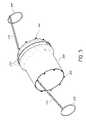
- FIG. 1is a perspective view of a medical treatment system in accordance with an embodiment of the present invention.
- FIG. 2Ais a side view of a stent frame shown in a compacted state.
- FIG. 2Bshows the stent frame of FIG. 2A in an expanded state.
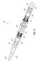
- FIG. 3Ais a side view of a distal assembly of the medical treatment system of FIG. 1 .
- FIG. 3Bis a cross-section view of the distal assembly of the medical treatment system of FIG. 3A .
- FIG. 4Ais a side view of a portion of a delivery device of the medical treatment system of FIG. 1 .
- FIGS. 4B-4Hshow additional views of detail elements of the delivery device shown in FIG. 4A .
- FIG. 5is a perspective view of a portion of the medical treatment system of FIG. 1 .
- FIG. 6is an expanded view of a portion of the medical treatment system of FIG. 1 .
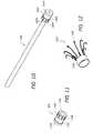
- FIGS. 7A-Care side views of the insertion and deployment of an implant of the medical treatment system of FIG. 1 at certain stages of operation.
- FIGS. 8A-Dare side views showing certain stages of operation of the extraction of the delivery device of the medical treatment system of FIG. 1 .
- FIG. 9is a perspective view of another embodiment of a distal assembly of a medical treatment system.
- FIG. 10is a perspective view of an elongate support member of the medical treatment system of FIG. 9 .
- FIG. 11is a perspective view of a mount ring of the medical treatment system of FIG. 9 .
- FIG. 12is a perspective view of a flexible member assembly of the medical treatment system of FIG. 9 .
- FIG. 13is a perspective view of a distal body of the medical treatment system of FIG. 9 .
- FIG. 14is a perspective view of a proximal body of the medical treatment system of FIG. 9 .
- FIGS. 15A-Dare side views of the medical treatment system of FIG. 9 shown at certain stages of the insertion and deployment of an implant.
- FIG. 15Eis a cross-section view of the distal assembly of the medical treatment system of FIG. 9 .
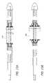
- FIGS. 16A-Bare side views of alternative controllers of the medical treatment system in accordance with the present invention.
- FIG. 17is a side view of an alternative controller of the medical treatment system in accordance with the present invention.
- the principles discussed hereincan be used in any application that would benefit from a prosthesis delivery device having repositioning capability and/or a reduced or negligible radial load transferred to the adjacent tissue surface during deployment of the prosthesis. While Applicant specifically provides examples of use of these principles in accordance with medical implant delivery devices and specifically delivery of stents, Applicant contemplates that other applications may benefit from this technology.
- the medical treatment system 100generally includes a controller 102 , otherwise referred to as a handle, and a distal assembly 112 .
- the handle 102includes a barrel 114 with a grip 110 located adjacent a proximal end of the barrel 114 .
- the handle 102further includes an actuator 104 located adjacent a distal end of the barrel.
- the barrel 114is affixed to a top most portion of the grip 110 .
- An access to a lumen 106is provided at the proximal end of the barrel 114 .
- the grip and barrelare sized to fit a typical physician's, or user's, hand to provide a stable grip and operating characteristics. Further, the shape and size of the barrel and grip are ergonomically shaped to provide a safe and reliable hold for the user.
- the lumen 106extends through the barrel 114 from the proximal end to the distal end, terminating at the actuator 104 , and providing the outlet and coupling interface for a flexible portion 116 , otherwise referred to as a proximal catheter.
- the proximal catheteris coupled to the handle 102 at a proximal end and is coupled to the distal assembly 112 at a distal end, establishing mechanical communication between the handle and the distal assembly.
- the actuatoras depicted in the illustrated embodiment, includes a rotating knob 122 that, depending on the direction of rotation, will longitudinally move elements of the proximal catheter 116 relative the handle.
- the elements of the proximal catheter 116can be moved toward and into, or away and out of, the handle 102 .
- the proximal cathetercan be substantially rigid, providing added control to the positioning of the distal assembly during the insertion and deployment operations discussed further below.
- the distal assembly 112is coupled to the handle 102 via the proximal catheter 116 , the length of which can vary according to a physician's needs.
- the proximal catheterincludes a flexible extension tube 118 , as shown in FIG. 3A , and a flexible sheath 120 .
- the flexible sheathincludes a through-hole, or lumen, disposed about a longitudinal axis along the full length of the sheath.
- the flexible sheathprovides a protective cover layer over the surface of the flexible extension tube 118 , yet allows the flexible extension tube 118 to slidingly move longitudinally within the sheath.
- the flexible extension tubeis a catheter having a lumen disposed about a longitudinal axis.
- the flexible extension tube proximal endis engagingly coupled to the actuator 104 and handle 102 .
- the flexible sheath proximal endis fixedly attached to the distal end of the barrel 114 adjacent the actuator 104 .
- the distal end of the flexible sheathis fixedly attached to the distal assembly 112 .
- the length of the flexible sheathestablishes the distance between the handle 102 and the distal assembly.
- the flexible extension tube and/or the flexible sheathcan be substantially rigid.
- the illustrated embodiment of medical treatment system 100is generally intended for minimally invasive procedures, thus the free length of the proximal catheter 116 between the distal assembly 112 and the handle 102 is shorter than if the system were primarily directed to a percutaneous procedure to access a desired location for deployment of the medical implant.
- the free length of the proximal catheter 116can be longer, as the medical treatment system can be utilized in percutaneous procedures in alternative embodiments of the system.
- the lumen 106in addition to providing an extended path of motion for the proximal catheter 116 flexible extension tube 118 , also provides a path and guideway for an endoscope 108 .
- the endoscopeis used to provide a physician visual access adjacent to the distal assembly 112 during the deployment operation of the medical treatment system 100 and is directed through the lumen 106 and the flexible extension tube to the distal assembly.
- FIGS. 2A and 2Ba front view of a medical implant 200 , otherwise referred to as a stent, is shown.
- the implant 200is configured to allow foreshortening of the frame body upon the longitudinal contraction of the implant 200 .
- the implant 200includes a frame 208 , legs 210 , otherwise referred to as anchors, a proximal interface 202 , a distal interface 204 , and an intermediate interface 206 .
- FIGS. 2A and 2Bonly show a frontside view of the implant 200 details, omitting the backside structure of the see-through device for clarity. Additionally, reference to implant 200 in further figures is depicted as a simpler cylinder shaped device for clarity and simplicity purposes only.
- the illustrated implant 200supports a heart valve body, and can be expanded from a compacted state as shown in FIG. 2A to an expanded state as shown in FIG. 2B .
- the illustrated implant 200preferably is a self-expanding stent constructed of a flexible material, preferably a shape memory material such as nitinol. As the implant is self-expanding, the implant 200 is in a fully opened state, as depicted in FIG. 2B , when relaxed in an unrestrained condition.
- the illustrated implant 200preferably is elongate from a proximal end 212 to a distal end 214 and is tubular with a longitudinal axis 216 and a generally circular cross section.
- stentscan have a non-circular cross section, such as a D-shape, an oval or an otherwise ovoid cross-sectional shape.
- a plurality of spaced apart proximal interfaces 202are provided at the proximal end 212 and distal interfaces 204 are provided at the distal end 214 of the implant 200 .
- Other embodimentsmay be constructed without proximal or distal interfaces 202 , 204 .
- the illustrated implant 200has a plurality of anchors 210 that extend from the transition 222 into the foreshortening portion 220 . Additional anchors 210 also extend from adjacent the distal end 214 into the foreshortening portion. The anchors extending in opposite directions establish a gap between their respective free ends, or proximal tip 234 and distal tip 236 . The longitudinal contraction of the implant creates a corresponding movement of the anchor 210 that moves the proximal and distal tips closer together. The movement together allows the anchors 210 to grasp onto tissues at a desired location so as to hold the implant in place.
- the non-foreshortening portion 218 of the illustrated implant 200comprises a plurality of rows or rings 226 a - c of circumferentially expansible elements, or struts 224 , arranged in a zigzag pattern.
- the struts 224are configured to expand and contract with a change in radius of the implant 200 .
- the stenthas three such rings 226 a - c . It is to be understood that more or fewer rings can be employed as desired to accomplish the purposes of this stent frame.
- each circumferential undulating strut 224joins an adjacent strut 224 at an apex 228 , 230 which is, in at least some embodiments, an area of preferential bending.
- the zigzag pattern of a first 226 a and a third ring 226 care generally in phase with one another, while the struts 224 of a second ring 226 b between the first and third rings 226 a , 226 b are generally out of phase with those of the first and third rings. It is to be understood that, in other embodiments, all or most of the rings can be in phase with one another or out of phase as desired.
- longitudinal struts 232extend transversely across the rings 226 a - c of the nonforeshortening portion 218 from the proximal end 212 of the implant 200 to the transition 222 . More particularly, each ring 226 shares a common longitudinal strut 232 .
- the longitudinal struts 232extend through apices 228 of adjacent rings 226 , and preferably extend the entire length of the nonforeshortening portion 218 .
- the longitudinal struts 232comprise a nonexpandable rod or bar.
- the apices 228 that are connected to the longitudinal struts 232are referred to as “connected” apices 228 .
- Apices 230 not connected to longitudinal struts 232are referred to as “free” apices 230 .
- the longitudinal struts 232are not substantially expandable in a longitudinal direction. As such, even though the undulating struts 224 provide flexibility in radial expansion or compaction, as the implant 200 changes radial size between the compacted and expanded states, the longitudinal length of the stent in the nonforeshortening portion 218 remains substantially unchanged.
- the distal assemblyincludes the implant 200 and a delivery device 316 .
- the delivery device 316further includes a proximal mount 300 , a distal mount 302 , a first elongate support member 304 , a second elongate support member 306 , a flanged sleeve 404 , a distal collar 406 , and a distal body 308 .
- the delivery device 316is used to accurately and safely deliver and deploy the implant, or stent, adjacent a desired location within the patient.
- the distal end of the pull rod 304includes an external thread 414 for coupling to an atraumatic nose cone or distal body 308 , as discussed in detail below.
- the proximal end of the pull rodis coupled to the proximal catheter 116 distal end via the flexible extension 118 , also discussed in further detail below.
- the second elongate support member 306is a rigid cylinder having an inner diameter with a diametral magnitude at least the same as the pull rod 304 , and a support 310 that is integral to the cylinder, as illustrated in FIG. 4A .
- the proximal stop 306is typically made of a rigid bio-compatible material for use in the human body, e.g. titanium, stainless steel, thermoplastic or thermoset resins, ceramic, or the like.
- the proximal stop 306is shorter than the pull rod 306 , generally being one to two times longer than the implant 200 although other varying lengths are possible.
- the proximal mount 300is a ring shaped device having an interior through-hole disposed about a longitudinal axis, an inner surface, an outer surface, a proximal face, a distal face, at least one guideslot 402 , and an annular groove 602 .
- the through-holeestablishes the diameter of the inner surface, and the inner surface diameter is substantially the same or slightly greater than the outer cylinder surface of a flanged sleeve 404 , as depicted in the illustrated embodiment of FIG. 4 .
- the radial thickness of the proximal mount 300preferably tapers from a thicker portion at the proximal face to a thinner portion at the distal face.
- the proximal face of the proximal mounthas a greater surface area, corresponding to the larger wall thickness of the ring member proximal end, as compared to the distal face of the proximal mount 300 .
- An annular groove 602depicted in the illustrated embodiment of FIG. 6 , is located on the proximal face of the proximal mount 304 .
- the annular groove 602extends all around the proximal face, encircling the through-hole about the longitudinal axis, and having a depth sufficient enough to receive a proximal ring 506 .
- the guideslot 402is more clearly depicted in the illustrated embodiment of FIGS. 4 and 6 .
- the at least one, or alternatively a plurality of, longitudinal grooves, or guideslots 402are located on the outer surface of the proximal mount 304 .
- the guideslotpreferably has a depth that is less than the total thickness of the proximal mount, and thus does not extend depthwise through to the inner surface of the proximal mount 300 .
- the plurality of guideslots 402will generally be equally spaced circumferentially about the proximal mount, although any spacing arrangement is possible.
- the flanged sleeve 404is a substantially cylindrical member having a flange, or lip, portion protruding radially outward from the outer surface of the cylinder and located adjacent the distal end of the flanged sleeve 404 .
- the inner surface of the flanged sleeve 404establishes a through-hole disposed about a longitudinal axis.
- the diameter of the through-holeis substantially the same as, or slightly greater than, the outer surface diameter of the proximal stop 306 .
- the outer surface diameter of the proximal flanged sleeve cylindrical portionis substantially the same, or slightly less than, the inner surface diameter of the proximal mount 300 .
- the cylindrical body of the flanged sleeve 404extends a longitudinal length that is longer than the longitudinal length of the proximal mount 300 .
- the distal collar 406is a ring, similar to a washer or a nut, having a through-hole disposed about a longitudinal axis.
- the longitudinal thickness of the collar 406is sufficient to include internal fastener threads on the inner surface diameter of the through-hole.
- the holeis sized substantially the same as pull rod 304 .
- the collar 406is made from a rigid, bio-compatible material, e.g. metal, plastic, Teflon, or the like.
- the collarcan be fabricated from a flexible member that deflects radially outward further than a rigid collar yet sufficiently capable of retaining the distal mount on the nose cone, e.g. a radial spring, an elastic material such as rubber, or the like.
- the distal body 308is generally a cone or frustum shaped, bullet nosed structure with bulbous rounded surfaces to advantageously provide an atraumatic gentle entry and movement within the patient's vasculature and mitigate the risk of injury to adjacent tissue due to the insertion of the distal assembly 112 within the patient.
- the cone shaped structure of the nose cone 308is disposed about a longitudinal axis, with the larger diameter base of the cone located adjacent a proximal end of the nose cone 308 and the decreasing, tapering, or arcing, diameter extends to a generously rounded distal end, or tip, of the nose cone 308 .
- the nose cone 308includes a through-hole disposed about the longitudinal axis along the full length from the proximal end to the distal end.
- the through-hole diameteris similar in magnitude to the inner diameter of the pull rod 304 .
- the nose cone 308 proximal end, or proximal face 416also includes a flange 408 and a neck 410 that extend proximally from the proximal end of the cone 308 , and are substantially centrally disposed about the longitudinal axis of the nose cone 308 .
- the flangehas a diameter smaller than the cone but larger than the neck.
- the flangeextends proximally a sufficient amount to create a shallow lip, such that a small gap exists when the distal mount is installed on the neck 410 , as described in detail below.
- the neckextends even further proximally, establishing a proximally protruding cylinder off of the nose cone 308 .
- the neckhas a smaller outer diameter than the flange and also includes internal fastener threads adjacent the proximal end.
- the through-hole of the nose cone 308provides an access point for the endoscope 108 , allowing the endoscope to pass through and exit out of the distal end, after which the endoscope 108 can then look back proximally on the distal assembly 112 and the implant 200 to provide visualization of the deployment process.
- An alternative embodiment of the nose cone 308includes an internal configuration providing an arcuate path, within the cone 308 itself, and exiting for example out of the side of the cone 308 . Such a configuration routes the endoscope 108 viewing tip back toward the implant prior to exiting the distal end of the nose cone 308 , placing the viewing tip nearer the implant.
- the endoscope 108can similarly exit any surface of the cone 308 that is sufficient to provide a visualization of the implant.
- an aperture or viewing portcan be formed in the pull rod 304 to enable an endoscope 108 to view the implant.
- the side view of delivery device 316further shows an embodiment of the support 310 .
- the support 310is an integral lip extending all around the proximal stop 306 and located adjacent the proximal end of the proximal stop 306 .
- the support 310has a substantially flat surface on the distal face, the face also being substantially normal to the longitudinal axis of the proximal stop 306 .
- the proximal face of the support 310has a tapered surface extending from the radially outermost surface, or diameter, of the support 310 to the outer surface of the proximal stop 306 cylindrical surface.
- the support 310provides a physical stop and support for the proximal mount 300 disposed about the proximal stop 306 , preventing the proximal mount from sliding or moving too far proximally as well as locating the proximal mount for installation of implant 200 onto delivery device 316 .
- the side view of delivery device 316further shows the proximal flexible member 312 , otherwise referred to as a proximal suture, and the distal flexible member 314 , referred to as a distal suture.
- the sutures 312 , 314attach the implant/stent 200 to the delivery device 316 .
- the length of the sutures 312 , 314can vary according to the size and location of the stent 200 and the delivery device 316 .
- the diameter of the sutures 312 , 314can vary as well, provided the sutures 312 , 314 can sustain the tensile loads required for the implant installation and deployment process.
- the sutures 312 , 314preferably are made of typical bio-compatible suture materials, e.g. nylon, polypropylene, polyglycolic acid, polyethylene, other thermoplastic polymers, cotton, silk, or the like. As will be discussed below, a plurality of sutures 312 , 314 are used to attach the implant to the delivery device 316 , as attachment is made at both the proximal and distal ends of the implant and the implant preferably is substantially centered about the delivery device 316 .
- the flexible memberscan have differing configuration, can be made of other materials, and may be substantially rigid.
- a perspective view of selected details of the distal assembly 112are shown, which includes a proximal ring 506 , a distal ring 508 , the proximal interface 202 , and the distal interface 204 , the anchor 210 , and an annular groove 602 .
- the proximal ring 506 and the distal ring 508otherwise referred to as proximal snap ring and distal snap ring, respectively, have similar characteristics in the illustrated embodiment; thus the description of features applies to both elements unless expressly described otherwise.
- the proximal ring 506is made of a small diameter member, generally a rigid bio-compatible material, e.g. metal, plastic, or the like, that is shaped to form a circle, where the circle generally lies on a common flat plane.
- the small diameter memberis formed in a circular manner such that the two ends of the member are adjacent each other, resulting in a slight gap between the ends.
- the proximal ring 506has a through-hole, establishing an inner diameter that is greater than the outer diameter of the cylindrical body of the flanged sleeve 404 .
- the diameter of the small diameter memberis less than the wall thickness of the proximal end of the proximal mount 300 .
- the gap between the ends of the memberprovides access for the sutures 312 connection to the ring and subsequently to the delivery device 316 .
- there is no gap in the ringcreating a continuous circle, whereby the sutures are individually tied onto the rings, or just folded over the ring and press fit into the annular groove, as discussed in further detail below, at the same time as the ring.
- an embodiment of the implant 200includes a plurality of the proximal interface 202 and the distal interface 204 , as shown.
- the proximal interface 202establishes a connection, or attachment, location for the suture 312 and the distal interface 204 establishes an attachment location for the suture 314 .
- the proximal interface 202 and distal interface 204in combination with the sutures 312 , 314 , connect the implant to the delivery device 316 .
- the shape and location of the interfaces 202 , 204can vary according to a physician's particular needs, and their shapes are not required to be identical, although such a configuration is possible.
- Their shapecan be any three-dimensional geometry providing connection capability to the suture 312 , e.g. an eyelet as shown, a hook, a radiused or sharp angled triangle element, a block, a sphere, a t-shaped leg, or the like, and any combination thereof.
- the suture contacting surfaces of the interfaces 202 , 204can vary as well, e.g. smooth, grooved, random discontinuous roughness, or the like, and any combination thereof.
- the interfacescan be located anywhere on the implant instead of at the proximal and distal ends provided sufficient tension on the implant 200 can be achieved to obtain a reduced diametral cross-section of the implant, as discussed in detail below.
- an intermediate interface 206is provided just proximal the foreshortening portion.
- proximal suturesconnect to the intermediate interface, extend along the non-foreshortening portion and through the proximal interface, and then to the proximal mount 300 .
- the illustrated embodiment of the implant 200has a plurality of anchors 210 for grasping the tissues of the vasculature at a desired location to hold the implant in place, as described in detail above.
- anchors 210for grasping the tissues of the vasculature at a desired location to hold the implant in place, as described in detail above.
- other embodiments for other usesmay not have anchors.
- Distal assembly 112is assembled to provide handle 102 controlled longitudinal displacement of the pull rod 304 and the nose cone 308 .
- the pull rod and the nose coneare rigidly coupled together and share a substantially common longitudinal axis extending through their respective through-holes, or lumens.
- the couplingis achieved by way of the external thread 414 on the distal end of the pull rod 304 , which threadingly engage the inner surface of the nose cone 308 through-hole, which includes a corresponding internal thread feature adjacent the nose cone proximal end.
- the nose cone 308prior to being coupled to the pull rod 304 , is first coupled to the distal mount 302 .
- the distal mount 304 through-holeis received on the nose cone 308 neck that protrudes proximally.
- the distal face of the distal mount 304having the increased cylinder wall thickness, is abutted against the flat surface of the nose cone flange, which is orthogonal to the longitudinal axis of the neck, nose cone and distal mount 304 , all of which are substantially co-axial.
- the distal mount 304is coupled via friction, where the diameters of the neck and the through-hole are sufficiently closely toleranced that a press fit occurs between the two details.
- the distal mount 304may be held in place by a distal collar 406 , which is a ring or washer having sufficient thickness to be threaded on the inner surfaces of a through-hole extending along a longitudinal axis.
- the through-holeis sized to threadingly engage the pull rod 304 external thread 414 .
- the distal mount 304would be threadingly pressed between the distal collar 406 and the nose cone 308 flange as the external threads of the pull rod engage both the nose cone 308 and the distal collar.
- the distal collar 406can be frictionally press fit on the distal end of pull rod 304 to abut the proximal face of the distal mount 304 .
- the distal mount 304is pressed between the nose cone 308 and the distal collar 406 by press fit friction and thread engagement, either alone or in combination.
- the flanged sleeve 404is configured to secure the proximal mount 300 onto the proximal stop 306 .
- the proximal mount 300is first inserted onto the flanged sleeve 404 , then the flanged sleeve 404 is inserted onto the proximal stop 306 . Further details of the insertion steps are such that the through-hole of the proximal mount 300 is sized to fit snugly onto the cylindrical body of the flanged sleeve 404 .
- the proximal mountis initially inserted onto the proximal end of the sleeve 404 and slid distally until the distal face of the proximal mount abuts the radially outward protruding lip 412 of the sleeve 404 .
- the through-hole of the flanged sleeve 404is sized to fit snugly, via friction of the two mating surfaces, onto the elongate cylinder surface of the proximal stop 306 .
- the proximal mount and the flanged sleevecan be an integral single-piece detail that achieves the described features and functions, eliminating the need for friction between the two details.
- the sleeve 404is then inserted onto the proximal stop 306 distal end and slidingly displaced proximally along the cylinder length toward the support 310 .
- a gap ‘A’exists between the proximal face of the proximal mount, where gap ‘A’, as shown in FIG. 3B , is established by the longer length accorded to the cylinder of the flanged sleeve 404 as compared to the longitudinal length of the proximal mount 300 . Therefore, in the illustrated embodiment of FIG.
- a proximal mount 300 moved all the way distally against the lip of the sleeve 404will result in the proximal end of the flanged sleeve 404 creating the gap ‘A’ between support 310 and mount 300 .
- the pull rod 304 proximal endis coupled to the distal end of the flexible extension tube 118 of the proximal catheter 116 , establishing longitudinal displacement capability and communication between the pull rod 306 and the handle 102 .
- the displacement capabilityis via the actuator 104 , because the flexible extension tube 118 of the proximal catheter 116 proximal end is coupled to the actuator 104 , the actuator 104 is located at the distal end of the handle 102 , and actuating the actuator pushes the flexible extension tube 118 of the proximal catheter longitudinally.
- the pull rod 304 proximal endterminates at the coupling to the flexible extension tube 118 of the proximal catheter 116 in the general area adjacent the proximal stop 306 proximal end when the delivery device 316 is assembled.
- the pull rod 304 and the flexible extension tube 118 of the proximal catheter 116extend through and slidingly engage within the proximal stop 306 , however the pull rod 304 consumes the majority of the longitudinal length within the proximal stop 306 when the stop and the pull rod are in the un-extended longitudinal state, as shown in FIGS. 3A , 3 B, and 4 A.
- Such a configurationadvantageously establishes a level of stiffness between the proximal mount 300 and the distal mount 302 that are affixed to the proximal stop 306 and the pull rod 304 , respectively, the portion of the delivery device that locates and deploys the implant 200 .
- the respective lengths, endpoints and connect locations between the proximal stop 306 and the pull rod 304can vary such that the coupling does not occur adjacent the proximal stop proximal end, provided sufficient control of the implant 200 is achieved.
- the proximal stopis not free to slide over the coupled flexible extension tube 118 and pull rod 306 .
- the flexible sheath 120that covers and protects the flexible extension tube 118 and is fixedly attached to the handle 102 at the proximal end of the sheath 120 , is abutted and/or coupled to the proximal end of the proximal stop 306 at the opposing distal end of the sheath 120 .
- proximal stop 306the proximal mount 300 , the flexible sheath 120 , and the handle 102 are coupled together, effectively functioning as a single member in the assembled state, with the proximal stop 306 being a stiffer relative portion of the effective member as compared to the flexible sheath 120 . All through-holes and inner diameters share substantially coincident longitudinal axes.
- the nose cone 308 , the distal mount 302 , the pull rod 304 , and the flexible extension tube 118are coupled together, also effectively functioning as a single member.
- the pull rod 304is a stiffer relative portion of the effective member as compared to the flexible extension tube 118 . All through-holes and inner diameters share substantially coincident longitudinal axes.
- the effective single member comprising the pull rod 304is the moving element, that moves relative the static proximal stop 306 effective member. The noted movement is controlled by the actuator 104 , by proximally and distally moving the nose cone 308 , the distal mount 302 , and the pull rod 304 through interaction with the flexible extension tube 118 .
- the pull rod 304 and its effective memberis in longitudinally movable communication with the handle 102 , and is located within, and thus moves within, the through-hole inner diameter of the proximal stop 306 and its effective member.
- the actuator 104moves the pull rod 304 longitudinally relative the proximal stop 306 and its effective member of the handle 102 , the flexible sheath 120 , the proximal stop 306 , and the proximal mount 300 .
- the pull rod 304 and the proximal stop 306share the same longitudinal axis, their respective axes being substantially coincident. Thus, the two effective members move relative each other.
- the pull rod 304extends through the proximal stop 306 and the relative longitudinal motion is between the outer diameter surface of the pull rod 304 and the inner diameter surface of the proximal stop 306 .
- the increased stiffness of the proximal stop 306 and the pull rod 304provides structural support to the distal assembly 112 that advantageously provides control during positioning and adjustment of the implant, as well as stability during any relative longitudinal motion between the proximal mount 300 and the distal mount 302 .
- the actuator 104is coupled to the flexible extension tube 118 , and actuation means occurs when the rotating knob 122 is rotated about the axis of the barrel 114 , and the lumen 106 .
- the actuation meanscan be any mechanical or electromechanical method known in the art, e.g. thread engagement, spring and detent, worm drive, or the like. It is understood also that, in other embodiments, the actuator 104 can be configured differently in the controller 102 , such as being a trigger or the like.
- distal assembly 112that readily positions, and is capable of readily repositioning, a medical implant at a desired location within a patient.
- the distal assembly 112advantageously provides for insertion, deployment and repositioning of the implant 200 without requiring external radial or longitudinal deployment forces that carry the risk of harming the tissue of and adjacent to the desired deployment location.
- the stent 200is temporarily secured by coupling means to the delivery device 316 for the insertion and deployment process, after which, when the implant is located as desired, the stent 200 is then removed from the delivery device 316 .
- the removal, or release of the coupling means, and the diameter of the delivery deviceallows the delivery device to be backed out of the insertion location safely, without harming the vascular tissue through which it passed to gain access to the desired location.
- the delivery device 316has the implant installed, as illustrated in FIGS. 3 , 5 , and 6 to establish a distal assembly 112 that is fully prepared for delivery and deployment within the patient's vasculature.
- the installation of implant 200utilizes the proximal interface 202 , the proximal sutures 312 , and the proximal ring 506 on the proximal side of the implant.
- installationutilizes the distal interface 204 , the distal sutures 314 , and the distal ring 508 .
- the installation sequence for the proximal and distal ends of the implant 200are identical, thus the description of the proximal end installation accordingly applies to the distal end of the implant 200 .
- the installation of the proximal end of implant 200entails coupling the plurality of proximal sutures 312 to the proximal interface 202 and the proximal mount 300 .
- the connection to the proximal mount 300occurs via a loop or a knot tied to the proximal ring 506 , after which the proximal ring 506 is placed in the annular groove 602 and the suture is aligned in the guideslot 402 to complete the attachment.
- the proximal suture 312may be individually tied by a knot at each of the proximal interface 202 and the proximal mount, or can be looped through both with a single knot tying both ends of the suture together. Variation can exist in where the individual knots are tied after individually looping the suture 312 through the proximal interface 202 and the proximal mount.
- a knotcan be placed adjacent the proximal mount 300 and the suture 312 simply looped through the proximal interface 202 .
- Thisallows for a single cut of the suture to be made that releases the implant without leaving suture material attached to the implant, but ensures the suture 312 remains attached to the proximal mount upon removal of the delivery device 316 from the patient's vasculature.
- FIG. 3illustrates the implant installed on the delivery device 316 in a longitudinally unrestrained condition, such that the diameter of the implant is at its self-expanding maximum.
- FIGS. 7A-C and 8 A-DThe above described details are combined and configured to provide a distal assembly 112 that readily positions, and is capable of readily repositioning, a medical implant at a desired location within a patient.
- the actuator 104is actuated to extend, or displace outwardly from handle 102 , the flexible extension tube 118 .
- the outward distal displacementis transmitted from the flexible extension tube 118 to the pull rod 304 and the distal mount 302 .
- This distal displacement of the distal mount 302lengthens the delivery device 316 distance between the proximal mount 300 and the distal mount 302 which results in a longitudinal tension on the proximal and distal flexible members 312 , 314 and thus, the implant 200 .
- the longitudinal tension applied to implantextends the longitudinal length and contracts the diameter of the implant 200 to a compacted state, as shown in FIG. 7A .
- the guideslots 402are smaller than the diameter of the nose cone. This allows the sutures 312 , 314 to be stretched in tension parallel to the longitudinal axis, which would result in a diameter of implant that approximates that of the sutures 312 , 314 .
- the distal assembly 112is then inserted, preferably in a minimally invasive manner, into the patient and the endoscope 108 is optionally inserted through the lumen 106 , the flexible extension tube 118 , the pull rod 304 , and the nose cone 308 to provide visualization assistance during the positioning and deployment procedure.
- the distal assemblyis inserted into the vasculature and directed toward the desired location 702 , which is the native annulus of the heart valve as illustrated in FIGS. 7A-B .
- the implant 200 legs 210are then centered about the desired location 702 , as illustrated in FIG. 7B , whereupon the actuator 104 is actuated to retract the flexible extension tube 118 , which moves the distal mount 302 proximally toward the handle 102 .
- This longitudinal shortening of the delivery device 316 between the proximal mount 300 and the distal mount 302allows the longitudinal length of the implant 200 to contract and the diameter of the implant to expand under the self-expanding properties of the implant.
- the foreshortening portion of the implantis contracted and the legs 210 are drawn closer together so as to grasp the heart valve native annulus 702 , as illustrated in FIG. 7C .
- the clinicianverifies whether the implant has been properly positioned. In one embodiment, position is verified by using the endoscope as discussed above. Should repositioning be desired, the clinician actuates the actuator 104 to extend the distal mount 302 and pull rod 304 such that the implant again extends longitudinally and contracts diametrally, and as a result, disengages from its improperly positioned state.
- the deployment processcan be repeated after repositioning the implant 200 into an adjusted, desired location 702 .
- the delivery device 316allows for the above described sequence of position, engage, and disengage, to be repeated until the implant 200 is properly positioned. It is to be understood that while making such adjustments, it may be sufficient to only partially radially contract the implant.
- the delivery device 316is removed from the implant and the patient's vasculature.
- the removal sequenceis initiated by severing the proximal sutures 312 as described above, leaving the totality of the sutures secured to the proximal mount 300 and ensuring no part of the sutures remain either free within the vasculature or attached to the implant 200 proximal interface 202 .
- the cliniciancan access, cut, and remove the proximal sutures while the delivery device remains in place.
- FIG. 8Aillustrates the proximal sutures severed, with the proximal sutures not shown for clarity.
- the delivery devicemay have a structure for detaching the sutures from the implant, yet retains the sutures so that they are removed from the patient with the device.
- Severing of all the proximal sutures 312allows partial retraction of the delivery device 316 by actuating the actuator 104 to retract the pull rod 304 in the proximal direction, bringing the distal mount 302 adjacent the proximal stop 300 .
- the entire system, except for the implant 200can be moved proximally to further back the delivery device out of the interior of the implant 200 .
- the delivery devicecan not be fully removed yet, however, because the distal sutures remain attached to the implant 200 .
- the distal mountsare retracted proximally a sufficient distance relative the implant 200 , as illustrated in FIG. 8B , to allow sufficient clearance and access to the distal sutures 314 so they can be cut without necessitating entry of the cutting device into the interior of the implant 200 .
- such a sequencedictates a preferred sizing of the pull rod 304 whereby the longitudinal length of the pull rod 304 is sufficiently long enough that at full extension two preferred conditions are met.
- Firstthat there is sufficient internal overlap between the pull rod 306 and the proximate stop 304 such that adequate stiffness to maintain positioning control of the delivery device exists.
- Secondthat the longitudinal length of the distal suture 314 is approximately at least as long as, and more preferably, 11 ⁇ 4 times as long as, the longitudinal length of the vasculature installed, or unrestrained, implant. The second condition ensures that the distal mount can move to a position so that severing of the distal sutures 314 can be performed without the cutting device entering the implant.
- the sutures 312 , 314can be configured such that the sutures are disconnected from the implant by other structures and methods, such as the sutures disengaging by other mechanical action from the implant 200 , knots being untied rather than severed, or the like. After the distal sutures 314 are severed, the delivery device 316 is free to move as a complete system proximally out of the vasculature and the patient, as illustrated in FIGS. 8C-D .
- the disclosed embodimentuses spring mechanisms in conjunction with the handle 102 to control the deployment of the implant 200 .
- the spring mechanismsinclude a proximal spring 918 , a distal spring 920 , and an intermediate spring 916 .
- the proximal and distal springs 918 , 920are preferably helical compression springs, substantially similar in spring constant, diameter and longitudinal length.
- Intermediate spring 916is preferably a helical compression spring, similar in diameter to springs 918 , 920 but has a spring constant that is less than that of proximal and distal springs 918 , 920 , thus requiring less compressive or tensile forces to compress or stretch the spring 920 .
- the illustrated embodimentfurther includes a first elongate support member 902 and a second elongate support member 904 that together control the longitudinal motion and displacement of the delivery device during the insertion and deployment of implant 200 .
- the first elongate support member 902otherwise referred to as a mount tube, is a rigid tube having a distal mount 1002 fixedly attached to the distal end of the mount tube 902 .
- the illustrated embodiment of the second elongate support member 904otherwise referred to as a pull rod, is a rigid tube in mechanical communication with a controller device such as handle 102 in a similar fashion as described above for distal assembly 112 .
- the pull rod 904has an outer surface diameter such that the pull rod 904 fits inside of the mount tube 902 and can slidingly engage the mount tube inner diameter.
- the distal mount 1002typically integrally or fixedly attached to the distal end of the mount tube 1002 , has a generally cylindrical shape that is coincident with the mount tube 902 .
- the distal mount 1002includes at least one guideslot 1004 , which is located on a proximal lip 1006 , a groove 1008 that is disposed circumferentially about the distal mount 1002 , and a distal lip 1010 located at the distal end of the mount tube 902 .
- the groove 1008is further established by and located between the proximal lip 1006 and the distal lip 1010 .
- the guideslot 1004extends longitudinally on the proximal lip 1006 .
- the illustrated embodimentfurther includes a proximal mount 906 , a proximal body 912 , a distal body 914 , a proximal flexible member 908 , and a distal flexible member 910 .
- the proximal mount 906illustrated in detail in FIG. 11 , includes a proximal lip 1104 , a groove 1102 that is disposed circumferentially about the proximal mount 906 , a distal lip 1106 , and at least one guideslot 1108 .
- the proximal mount 906is configured in a similar arrangement as the distal mount 1002 except the proximal mount 906 includes a through-hole having a longitudinal axis that is sized to slidingly engage the outer surface diameter of the mount tube 902 . Additionally, the proximal mount is symmetrically reversed longitudinally relative to the distal mount 1002 , such that, for example, the guideslots are located on the distal end of the proximal mount 906 .
- the proximal flexible member 908 , and the distal flexible member 910are identical, comprised of a flexible member assembly 1200 as illustrated in FIG. 12 , but symmetrically opposed on their common longitudinal axis about the implant 200 in the assembled arrangement.
- the flexible member 1200includes a plurality of arms 1202 , and a ring 1204 .
- the arms 1202are J-shaped wire-type elements, where the elongate portion is coupled to the ring 1204 and the radiused portion is biased to flare radially outward when the arms 1202 are in an unrestrained condition.
- the ring 1204has a longitudinal length and an inner and outer diameter that is configured to mate with the grooves 1102 and 1008 on the respective mounts.
- the flexible member assembly 1200preferably is comprised of a semi-rigid, or resiliently flexible material, e.g. metal, plastic, or the like. In alternative embodiments the flexible members can be substantially rigid and still provide the longitudinal tension required as described below.
- the proximal body 912includes two cylindrical portions, a smaller diameter cylinder sized to slidingly engage the mount tube 902 and the larger diameter cylinder sized to receive the proximal spring 918 and the proximal mount 906 .
- the distal body 914as illustrated in FIG. 13 includes a head 1300 having a conical shape similar to the nose cone 308 and a cylindrical body sized and configured to receive the distal spring 920 and the distal mount 1002 .
- the implant 200preferably includes proximal and distal interfaces 202 , 204 as described above.
- the distal end of the pull rod 904is coupled to the head 1300 of the distal body 914 , within the through-hole lumen that is disposed about the longitudinal axis of the head 1300 .
- the distal spring 920is disposed about the pull rod 904 and located between head 1300 and the distal mount 1002 within the cylindrical portion of the distal body 914 .
- the mount tube 902has several details installed over the cylindrical tube.
- Intermediate spring 916is inserted on the proximal end of the mount tube 902 distally until contacting the proximal end of the distal mount 1002 .
- the distal end of the proximal mount 906is placed onto the mount tube 902 and the mount 906 is slidingly engaged distally until contacting the proximal end of the intermediate spring 916 .
- the proximal spring 918is then inserted in a like manner, followed by the larger diameter distal end of the proximal body 912 .
- the distal end of the proximal body 912is inserted on the mount tube 902 until an inner orthogonal flat surface, which transitions the larger cylinder to the smaller cylinder of the body 912 , contacts the proximal end of the proximal spring 918 .
- the flexible sheath 120is then coupled to the proximal end of the proximal body 912 , to establish a fixed distance between the proximal body and the controller 102 .
- the proximal and distal mounts 906 , 1002will also have the proximal and distal flexible members 908 , 910 installed onto the respective mounts, such that the J-shaped arms are oriented to couple to the implant 200 at the proximal and distal interfaces 202 , 204 .
- the distal spring 920is then placed over the pull rod distal end, and finally the distal body 914 is coupled to the pull rod distal end.
- the proximal mount 906is effectively coupled to the distal mount 1002 via the distal flexible members 908 , 910 and the implant 200 , with the intermediate spring 916 located between the two mounts 906 and 1002 .
- the intermediate spring 916urges the mounts longitudinally apart, which supplies tension to retain the implant 200 in a longitudinally extended and diametrally contracted configuration as shown.
- the flexible sheath 120abuts the proximal end of the proximal body 912 .
- longitudinal displacement of the pull rod 904 due to extraction or contraction via actuating of the actuator 104occurs within the flexible sheath 120 .
- the mount tube 902 and the aforementioned installed details on the mount tube 902essentially float between the nose cone 1300 and the flexible sheath 120 . This floating condition allows for operation of the delivery device 900 to insert and deploy the implant 200 .
- the proximal body 912is prevented from moving toward the handle 102 by the sheath 120 .
- the implant 200 installation on the delivery device 900completes the assembly of the distal assembly 900 , which is achieved as follows.
- the intermediate spring 916is compressed to hold the proximal and distal mounts close enough together to allow the arms 1202 to be coupled to the proximal and distal interfaces 202 , 204 of the unrestrained self-expanded implant.
- the implant 200can be longitudinally extended in tension prior to the coupling to the flexible members to allow the interfaces to complete the coupling, or further still there can be a combination of the two, compression of intermediate spring 916 and longitudinal tensile extension of implant.
- the intermediate springis released and allowed to expand, extending the implant longitudinally, as the spring constant is chosen to be sufficient to overcome any resistance in the self-expanding implant to such longitudinal extension.
- the delivery deviceis initially in the compacted state shown in FIG. 15A .
- the pull rod 904 distal endis coupled to the distal body 914 and the pull rod 904 proximal end is coupled to the actuator 104 .
- the actuator 104is configured to move the pull rod 904 toward the handle 102 when actuated, so as to pull the distal body 914 toward the handle 102 .
- This relative movement between the distal body 914 and proximal body 912is resisted by each of the distal spring 920 , proximal spring 918 , and intermediate spring 916 .
- the intermediate spring 916has a lower spring constant, the intermediate spring 916 will contract first before either the proximal or distal springs 918 , 920 .
- the actuator 104is actuated to begin the longitudinal contraction and engaging of the adjacent surfaces of the desired location 702 as described above, and as depicted in FIG. 15B .
- the distal assemblycan be disengaged and repositioned as discussed above.
- the delivery device 900is next removed from the implant by releasing the arms 1202 and extracting the delivery device.
- removaloccurs by further actuation of the actuator 104 in a manner that moves the pull rod 904 distally away from the handle 102 and concurrently moves the distal body proximally toward the handle 102 .
- the intermediate spring 916will eventually bottom out in compression and stop contracting.
- the actuatorcontinues to move the pull rod 904 proximally, the higher spring constant proximal and distal springs 918 , 920 , which did not contract previously because the spring constant is higher than the intermediate spring 916 , will then contract under the continued compressive forces created by the distal motion of the actuator 104 .
- one or more physical stopsare disposed on the mount tube 902 to stop further compression of the intermediate spring.
- the distal body 914 and the proximal body 912move toward the implant and the cylindrical bodies adjacent the implant 200 encompass the arms 1202 of the proximal and distal flexible members 908 , 910 .
- the motion, combined with movement of the flexible member 908 , 910 toward the center of the implant 200 , of the cylindrical bodies encompassing the arms 1202draws the arms radially inward toward the longitudinal axis, to be parallel to the inner diameter surface of the bodies. This motion brings the j-shaped radiused ends of the arms 1202 out of the proximal and distal interfaces 202 , 204 of the implant.
- the distal assemblyis now free to be withdrawn from the interior of the implant and the patient's vasculature system.
- the lumen extending through the delivery device 900is not shown in the cross-section view of FIG. 15E for clarity.
- the delivery deviceincludes a detent preventing movement of the pull rod 904 proximally to release the arms 1202 . Once the clinician has verified the correct positioning of the implant 200 , the detent may be actuated to allow further movement of the pull rod 904 .
- FIG. 16Adepicts one embodiment of a handle having an actuator 104 driven by rotation of an actuator knob 122 .
- Rotation of the knob 122engages the flexible extension tube 118 of the proximal catheter 116 so as to longitudinally displace pull rod either proximally or distally, depending on the rotation direction of the knob.
- the engagementcan be applied by various methods, such as rotation of threads or the like.
- a lever 1600is optionally included and provides a secondary stop mechanism, such as a detent, that prevents actuation of the flexible extension tube 118 of the proximal catheter unless the lever 1600 is biased against the grip 110 , which releases the detent stop mechanism and allows actuation of the proximal catheter.
- a secondary stop mechanismsuch as a detent
- a lever and spring loaded embodimentis shown to provide longitudinal displacement capability for the handle 102 .
- the handle 102includes a lever 1600 , and actuator spring 1602 , and a locking mechanism 1604 .
- the lever 1600extends downward from the distal side of the grip 110 . This orientation allows a user to hold the grip 110 and concurrently actuate the lever proximally and distally about the connection pivot point that is located at the top of the grip 110 adjacent the barrel 114 .
- the spring 1602is disposed within the barrel about the outer diameter surface of the lumen 106 and the proximal catheter 116 .
- the proximal end of the spring 1602is coupled to the top end of the lever 1600 and the distal end of the spring 1602 is coupled to the distal end of the handle 102 or the barrel 114 .
- the springis located in a compressed configuration, imparting a tensile force on the handle 102 and the lever 1602 .
- the tensile force of the spring 1602biases the lever in a distal direction about its pivot connection to the handle 102 .
- the locking mechanism 1604applies a friction force to the flexible extension tube 118 of the proximal catheter 116 preventing longitudinal displacement.
- the lever 1600moves the catheter and the spring 1602 biases the lever 1600 to the closed position, which is away from the grip 110 , as shown in FIG. 16B .
- Actuationoccurs when the lever 1600 is pulled toward the grip 110 and the lever pushes the proximal catheter distally, so as to also push the pull rod distally.
- Lock 1604then holds the proximal catheter in place.
- the sequencecan be reversed, such as for the spring driven delivery device 900 , such that actuation of the lever 1600 pulls on the flexible extension tube 118 of the proximal catheter to deploy the implant.
- the lock 1604can be configured to actuate a detent that prevents advancement or retraction beyond a specified distance, and the detent can be disengaged upon manipulation of the lock 1604 .
- the handle 1700includes a knob 1702 , a grip 1704 , a dual spring 1708 , and an actuator 1706 .
- the knob 1702is coupled to a longitudinal neck that is further coupled to the flexible extension tube 118 of the proximal catheter 116 .
- the knob 1702rests in the palm of the user, or physician.
- the grip 1704includes at least one radially extending arm that is held by the users fingers.
- the actuator 1706extends radially and is actuated by the users thumb. The actuation of the actuator 1706 engages the spring 1708 to selectively lock or allow actuation of the flexible extension tube of the proximal catheter in conjunction with the longitudinal depression of the knob 1702 by the user.
- a pump of the lever 1600 or the knob 1702 or rotation of actuator knob 122allows radial expansion of an associated implant by displacing the flexible extension tube 118 distally or proximally as appropriate.
- the proximal and distal mounts 300 and 302must move toward each other to allow the implant to diametrally expand and subsequently disengage from the implant 200 . This is achieved by a plurality of means, both actively and passively.
- the rotation of knob 122allows precise control in both longitudinal directions.
- the dual springwill contract and displace the flexible extension tube 118 of the proximal catheter 116 in the proximal direction.
- An alternative method to the release mechanismis to utilize a detent that will establish a final click lock during the extension of the flexible extension tube 118 , and such click with deploy and fix into longitudinal place the flexible extension tube 118 .
- a passive mechanismis possible that the mounts are displaced past the point of full expansion and then drop away to disengage freely from the implant 200 .
- features discussed hereincan be combined with other implant delivery apparatus and methods.
- the implantin addition to securing the implant under tension as in embodiments discussed above, the implant is also compacted and fit within a sheath, which helps to keep the implant in a small diametral configuration.
- the sheathis located on the outer surface diameter of the implant and retains the implant in a diametrally constrained state. In such a configuration, the system holding the implant under tension is a primary restraint system and the sheath is part of a secondary restraint system.
- the delivery devicemay include a secondary restraint structure comprising a line or ribbon extending from a portion of the delivery device and circumferentially encircling the outside of the implant between proximal and distal ends of the implant. At least one end of the line or ribbon can be tightened or let out by the operator manipulating the controller.
- This secondary restraintworks in concert with the proximal and distal mounts to control radial expansion of the implant, and when the proximal and distal mounts are moved toward one another, the clinician can simultaneously let out the ribbon so as to allow the implant to expand. Once the implant is deployed, the ribbon can be retracted into the delivery device and removed from the patient.
Landscapes
- Health & Medical Sciences (AREA)
- Cardiology (AREA)
- Engineering & Computer Science (AREA)
- Biomedical Technology (AREA)
- Life Sciences & Earth Sciences (AREA)
- Transplantation (AREA)
- Heart & Thoracic Surgery (AREA)
- Vascular Medicine (AREA)
- Oral & Maxillofacial Surgery (AREA)
- Animal Behavior & Ethology (AREA)
- General Health & Medical Sciences (AREA)
- Public Health (AREA)
- Veterinary Medicine (AREA)
- Mechanical Engineering (AREA)
- Prostheses (AREA)
- Media Introduction/Drainage Providing Device (AREA)
Abstract
Description
Claims (14)
Priority Applications (4)
| Application Number | Priority Date | Filing Date | Title |
|---|---|---|---|
| US12/572,180US8337541B2 (en) | 2008-10-01 | 2009-10-01 | Delivery system for vascular implant |
| US13/725,896US8911455B2 (en) | 2008-10-01 | 2012-12-21 | Delivery system for vascular implant |
| US14/551,338US9597183B2 (en) | 2008-10-01 | 2014-11-24 | Delivery system for vascular implant |
| US15/004,823US9744039B2 (en) | 2008-10-01 | 2016-01-22 | Delivery system for vascular implant |
Applications Claiming Priority (2)
| Application Number | Priority Date | Filing Date | Title |
|---|---|---|---|
| US13676008P | 2008-10-01 | 2008-10-01 | |
| US12/572,180US8337541B2 (en) | 2008-10-01 | 2009-10-01 | Delivery system for vascular implant |
Related Child Applications (1)
| Application Number | Title | Priority Date | Filing Date |
|---|---|---|---|
| US13/725,896ContinuationUS8911455B2 (en) | 2008-10-01 | 2012-12-21 | Delivery system for vascular implant |
Publications (2)
| Publication Number | Publication Date |
|---|---|
| US20100082089A1 US20100082089A1 (en) | 2010-04-01 |
| US8337541B2true US8337541B2 (en) | 2012-12-25 |
Family
ID=41328427
Family Applications (4)
| Application Number | Title | Priority Date | Filing Date |
|---|---|---|---|
| US12/572,180Expired - Fee RelatedUS8337541B2 (en) | 2008-10-01 | 2009-10-01 | Delivery system for vascular implant |
| US13/725,896ActiveUS8911455B2 (en) | 2008-10-01 | 2012-12-21 | Delivery system for vascular implant |
| US14/551,338Expired - Fee RelatedUS9597183B2 (en) | 2008-10-01 | 2014-11-24 | Delivery system for vascular implant |
| US15/004,823ActiveUS9744039B2 (en) | 2008-10-01 | 2016-01-22 | Delivery system for vascular implant |
Family Applications After (3)
| Application Number | Title | Priority Date | Filing Date |
|---|---|---|---|
| US13/725,896ActiveUS8911455B2 (en) | 2008-10-01 | 2012-12-21 | Delivery system for vascular implant |
| US14/551,338Expired - Fee RelatedUS9597183B2 (en) | 2008-10-01 | 2014-11-24 | Delivery system for vascular implant |
| US15/004,823ActiveUS9744039B2 (en) | 2008-10-01 | 2016-01-22 | Delivery system for vascular implant |
Country Status (4)
| Country | Link |
|---|---|
| US (4) | US8337541B2 (en) |
| EP (2) | EP2845569A1 (en) |
| CA (1) | CA2739275C (en) |
| WO (1) | WO2010040009A1 (en) |
Cited By (73)
| Publication number | Priority date | Publication date | Assignee | Title |
|---|---|---|---|---|
| US8652203B2 (en) | 2010-09-23 | 2014-02-18 | Cardiaq Valve Technologies, Inc. | Replacement heart valves, delivery devices and methods |
| US20140172075A1 (en)* | 2010-04-21 | 2014-06-19 | Medtronic, Inc. | Transcatheter Prosthetic Heart Valve Delivery System and Method with Controlled Expansion of Prosthetic Heart Valve |
| US8795356B2 (en) | 2009-04-15 | 2014-08-05 | Cardiaq Valve Technologies, Inc. | Vascular implant |
| US8894702B2 (en) | 2008-09-29 | 2014-11-25 | Cardiaq Valve Technologies, Inc. | Replacement heart valve and method |
| US8911455B2 (en) | 2008-10-01 | 2014-12-16 | Cardiaq Valve Technologies, Inc. | Delivery system for vascular implant |
| US9241790B2 (en) | 2010-05-05 | 2016-01-26 | Neovasc Tiara Inc. | Transcatheter mitral valve prosthesis |
| US9308087B2 (en) | 2011-04-28 | 2016-04-12 | Neovasc Tiara Inc. | Sequentially deployed transcatheter mitral valve prosthesis |
| USD755384S1 (en) | 2014-03-05 | 2016-05-03 | Edwards Lifesciences Cardiaq Llc | Stent |
| US9326873B2 (en) | 2007-10-12 | 2016-05-03 | Spiration, Inc. | Valve loader method, system, and apparatus |
| US9345573B2 (en)* | 2012-05-30 | 2016-05-24 | Neovasc Tiara Inc. | Methods and apparatus for loading a prosthesis onto a delivery system |
| US9433514B2 (en) | 2005-11-10 | 2016-09-06 | Edwards Lifesciences Cardiaq Llc | Method of securing a prosthesis |
| US9480560B2 (en) | 2009-09-29 | 2016-11-01 | Edwards Lifesciences Cardiaq Llc | Method of securing an intralumenal frame assembly |
| US9554897B2 (en) | 2011-04-28 | 2017-01-31 | Neovasc Tiara Inc. | Methods and apparatus for engaging a valve prosthesis with tissue |
| US9572665B2 (en) | 2013-04-04 | 2017-02-21 | Neovasc Tiara Inc. | Methods and apparatus for delivering a prosthetic valve to a beating heart |
| US9579193B2 (en) | 2010-09-23 | 2017-02-28 | Transmural Systems Llc | Methods and systems for delivering prostheses using rail techniques |
| US9622752B2 (en) | 2003-08-08 | 2017-04-18 | Spiration, Inc. | Bronchoscopic repair of air leaks in a lung |
| US20170156859A1 (en)* | 2015-12-02 | 2017-06-08 | Edwards Lifesciences Corporation | Suture deployment of prosthetic heart valve |
| US9681951B2 (en) | 2013-03-14 | 2017-06-20 | Edwards Lifesciences Cardiaq Llc | Prosthesis with outer skirt and anchors |
| US9724083B2 (en) | 2013-07-26 | 2017-08-08 | Edwards Lifesciences Cardiaq Llc | Systems and methods for sealing openings in an anatomical wall |
| US9730791B2 (en) | 2013-03-14 | 2017-08-15 | Edwards Lifesciences Cardiaq Llc | Prosthesis for atraumatically grasping intralumenal tissue and methods of delivery |
| US9763657B2 (en) | 2010-07-21 | 2017-09-19 | Mitraltech Ltd. | Techniques for percutaneous mitral valve replacement and sealing |
| US9788941B2 (en) | 2010-03-10 | 2017-10-17 | Mitraltech Ltd. | Axially-shortening prosthetic valve |
| USD800908S1 (en) | 2016-08-10 | 2017-10-24 | Mitraltech Ltd. | Prosthetic valve element |
| US9925045B2 (en) | 2013-10-21 | 2018-03-27 | Medtronic Vascular Galway | Systems, devices and methods for transcatheter valve delivery |
| US9974651B2 (en) | 2015-02-05 | 2018-05-22 | Mitral Tech Ltd. | Prosthetic valve with axially-sliding frames |
| US10045845B2 (en) | 2012-11-13 | 2018-08-14 | Mitraltech Ltd. | Percutaneously-deliverable mechanical valve |
| US10045765B2 (en) | 2014-03-27 | 2018-08-14 | Transmural Systems Llc | Devices and methods for closure of transvascular or transcameral access ports |
| US10123788B2 (en) | 2011-05-13 | 2018-11-13 | Spiration, Inc. | Deployment catheter |
| US10201442B2 (en) | 2013-03-14 | 2019-02-12 | Spiration, Inc. | Valve loader method, system, and apparatus |
| USD841813S1 (en) | 2017-08-03 | 2019-02-26 | Cardiovalve Ltd. | Prosthetic heart valve element |
| US10226341B2 (en) | 2011-08-05 | 2019-03-12 | Cardiovalve Ltd. | Implant for heart valve |
| US10231831B2 (en) | 2009-12-08 | 2019-03-19 | Cardiovalve Ltd. | Folding ring implant for heart valve |
| US10245143B2 (en) | 2011-08-05 | 2019-04-02 | Cardiovalve Ltd. | Techniques for percutaneous mitral valve replacement and sealing |
| US10321998B2 (en) | 2010-09-23 | 2019-06-18 | Transmural Systems Llc | Methods and systems for delivering prostheses using rail techniques |
| US10390952B2 (en) | 2015-02-05 | 2019-08-27 | Cardiovalve Ltd. | Prosthetic valve with flexible tissue anchor portions |
| US10398551B2 (en) | 2011-09-22 | 2019-09-03 | Transmural Systems Llc | Devices, systems and methods for repairing lumenal systems |
| US10426482B2 (en) | 2015-09-15 | 2019-10-01 | The United States Of America, As Represented By The Secretary, Department Of Health And Human Services | Devices and methods for effectuating percutaneous Glenn and Fontan procedures |
| US10492908B2 (en) | 2014-07-30 | 2019-12-03 | Cardiovalve Ltd. | Anchoring of a prosthetic valve |
| US10531866B2 (en) | 2016-02-16 | 2020-01-14 | Cardiovalve Ltd. | Techniques for providing a replacement valve and transseptal communication |
| US10575948B2 (en) | 2017-08-03 | 2020-03-03 | Cardiovalve Ltd. | Prosthetic heart valve |
| US10583002B2 (en) | 2013-03-11 | 2020-03-10 | Neovasc Tiara Inc. | Prosthetic valve with anti-pivoting mechanism |
| US10631982B2 (en) | 2013-01-24 | 2020-04-28 | Cardiovale Ltd. | Prosthetic valve and upstream support therefor |
| US10856975B2 (en) | 2016-08-10 | 2020-12-08 | Cardiovalve Ltd. | Prosthetic valve with concentric frames |
| US10888421B2 (en) | 2017-09-19 | 2021-01-12 | Cardiovalve Ltd. | Prosthetic heart valve with pouch |
| US11246704B2 (en) | 2017-08-03 | 2022-02-15 | Cardiovalve Ltd. | Prosthetic heart valve |
| US11291545B2 (en) | 2011-08-05 | 2022-04-05 | Cardiovalve Ltd. | Implant for heart valve |
| US11344410B2 (en) | 2011-08-05 | 2022-05-31 | Cardiovalve Ltd. | Implant for heart valve |
| US11382746B2 (en) | 2017-12-13 | 2022-07-12 | Cardiovalve Ltd. | Prosthetic valve and delivery tool therefor |
| US11633277B2 (en) | 2018-01-10 | 2023-04-25 | Cardiovalve Ltd. | Temperature-control during crimping of an implant |
| US11653910B2 (en) | 2010-07-21 | 2023-05-23 | Cardiovalve Ltd. | Helical anchor implantation |
| US11779742B2 (en) | 2019-05-20 | 2023-10-10 | Neovasc Tiara Inc. | Introducer with hemostasis mechanism |
| US11793633B2 (en) | 2017-08-03 | 2023-10-24 | Cardiovalve Ltd. | Prosthetic heart valve |
| US11998447B2 (en) | 2019-03-08 | 2024-06-04 | Neovasc Tiara Inc. | Retrievable prosthesis delivery system |
| US12016774B2 (en) | 2020-05-08 | 2024-06-25 | Medtronic Vascular, Inc. | Delivery system for prosthetic valve device having controlled release of inflow and outflow ends |
| US12029646B2 (en) | 2017-08-03 | 2024-07-09 | Cardiovalve Ltd. | Prosthetic heart valve |
| US12053379B2 (en) | 2016-08-01 | 2024-08-06 | Cardiovalve Ltd. | Minimally-invasive delivery systems |
| US12053378B2 (en) | 2012-11-07 | 2024-08-06 | Transmural Systems Llc | Devices, systems and methods for repairing lumenal systems |
| US12109111B2 (en) | 2015-12-15 | 2024-10-08 | Neovasc Tiara Inc. | Transseptal delivery system |
| US12138160B2 (en) | 2014-11-26 | 2024-11-12 | Edwards Lifesciences Corporation | Transcatheter prosthetic heart valve and delivery system |
| US12285330B2 (en) | 2013-03-14 | 2025-04-29 | Edwards Lifesciences Cardiaq Llc | Prosthesis for atraumatically grasping intralumenal tissue and methods of delivery |
| US12295837B2 (en) | 2016-05-12 | 2025-05-13 | St. Jude Medical, Cardiology Division, Inc. | Mitral heart valve replacement |
| US12295584B2 (en) | 2015-03-20 | 2025-05-13 | Edwards Lifesciences Corporation | Systems and methods for delivering an implantable device |
| US12295839B2 (en) | 2019-04-23 | 2025-05-13 | Edwards Lifesciences Corporation | Motorized implant delivery system |
| US12303385B2 (en) | 2013-02-04 | 2025-05-20 | Edwards Lifesciences Corporation | Method of implanting a spacer body in a mitral valve |
| US12310853B2 (en) | 2014-09-28 | 2025-05-27 | Edwards Lifesciences Corporation | Systems and methods for treating cardiac dysfunction |
| US12357459B2 (en) | 2020-12-03 | 2025-07-15 | Cardiovalve Ltd. | Transluminal delivery system |
| US12364587B2 (en) | 2020-12-18 | 2025-07-22 | Edwards Lifesciences Corporation | Storage jar assembly for a prosthetic heart valve |
| US12376961B2 (en) | 2008-05-01 | 2025-08-05 | Edwards Lifesciences Corporation | Method of implanting a prosthetic heart valve assembly |
| US12376956B2 (en) | 2017-09-01 | 2025-08-05 | Transmural Systems Llc | Percutaneous shunt devices and related methods |
| US12403004B2 (en) | 2014-06-06 | 2025-09-02 | Edwards Lifesciences Corporation | Method for replacing a tricuspid valve |
| US12409031B2 (en) | 2009-12-04 | 2025-09-09 | Edwards Lifesciences Corporation | Prosthetic valve having a multi-part frame |
| US12427016B2 (en) | 2009-04-29 | 2025-09-30 | Edwards Lifesciences Corporation | Apparatus and method for replacing a diseased cardiac valve |
| US12440335B2 (en) | 2023-05-11 | 2025-10-14 | Edwards Lifesciences Corporation | Delivery system for aided replacement valve recapture and repositioning post-deployment |
Families Citing this family (181)
| Publication number | Priority date | Publication date | Assignee | Title |
|---|---|---|---|---|
| EP1309289A2 (en) | 2000-08-18 | 2003-05-14 | Atritech, Inc. | Expandable implant devices for filtering blood flow from atrial appendages |
| US20030050648A1 (en) | 2001-09-11 | 2003-03-13 | Spiration, Inc. | Removable lung reduction devices, systems, and methods |
| US6592594B2 (en) | 2001-10-25 | 2003-07-15 | Spiration, Inc. | Bronchial obstruction device deployment system and method |
| US20030181922A1 (en) | 2002-03-20 | 2003-09-25 | Spiration, Inc. | Removable anchored lung volume reduction devices and methods |
| US20030216769A1 (en) | 2002-05-17 | 2003-11-20 | Dillard David H. | Removable anchored lung volume reduction devices and methods |
| US7100616B2 (en) | 2003-04-08 | 2006-09-05 | Spiration, Inc. | Bronchoscopic lung volume reduction method |
| US8603160B2 (en) | 2003-12-23 | 2013-12-10 | Sadra Medical, Inc. | Method of using a retrievable heart valve anchor with a sheath |
| US7381219B2 (en) | 2003-12-23 | 2008-06-03 | Sadra Medical, Inc. | Low profile heart valve and delivery system |
| US7959666B2 (en) | 2003-12-23 | 2011-06-14 | Sadra Medical, Inc. | Methods and apparatus for endovascularly replacing a heart valve |
| US8579962B2 (en) | 2003-12-23 | 2013-11-12 | Sadra Medical, Inc. | Methods and apparatus for performing valvuloplasty |
| US8343213B2 (en) | 2003-12-23 | 2013-01-01 | Sadra Medical, Inc. | Leaflet engagement elements and methods for use thereof |
| US20120041550A1 (en) | 2003-12-23 | 2012-02-16 | Sadra Medical, Inc. | Methods and Apparatus for Endovascular Heart Valve Replacement Comprising Tissue Grasping Elements |
| US11278398B2 (en) | 2003-12-23 | 2022-03-22 | Boston Scientific Scimed, Inc. | Methods and apparatus for endovascular heart valve replacement comprising tissue grasping elements |
| US20050137687A1 (en) | 2003-12-23 | 2005-06-23 | Sadra Medical | Heart valve anchor and method |
| US8828078B2 (en) | 2003-12-23 | 2014-09-09 | Sadra Medical, Inc. | Methods and apparatus for endovascular heart valve replacement comprising tissue grasping elements |
| US8840663B2 (en) | 2003-12-23 | 2014-09-23 | Sadra Medical, Inc. | Repositionable heart valve method |
| US9526609B2 (en) | 2003-12-23 | 2016-12-27 | Boston Scientific Scimed, Inc. | Methods and apparatus for endovascularly replacing a patient's heart valve |
| DE102005003632A1 (en) | 2005-01-20 | 2006-08-17 | Fraunhofer-Gesellschaft zur Förderung der angewandten Forschung e.V. | Catheter for the transvascular implantation of heart valve prostheses |
| US7780723B2 (en) | 2005-06-13 | 2010-08-24 | Edwards Lifesciences Corporation | Heart valve delivery system |
| US20070213813A1 (en) | 2005-12-22 | 2007-09-13 | Symetis Sa | Stent-valves for valve replacement and associated methods and systems for surgery |
| EP1988851A2 (en) | 2006-02-14 | 2008-11-12 | Sadra Medical, Inc. | Systems and methods for delivering a medical implant |
| US7691151B2 (en) | 2006-03-31 | 2010-04-06 | Spiration, Inc. | Articulable Anchor |
| WO2008013915A2 (en) | 2006-07-28 | 2008-01-31 | Arshad Quadri | Percutaneous valve prosthesis and system and method for implanting same |
| US9408607B2 (en)* | 2009-07-02 | 2016-08-09 | Edwards Lifesciences Cardiaq Llc | Surgical implant devices and methods for their manufacture and use |
| US7896915B2 (en) | 2007-04-13 | 2011-03-01 | Jenavalve Technology, Inc. | Medical device for treating a heart valve insufficiency |
| US9149379B2 (en) | 2007-07-16 | 2015-10-06 | Cook Medical Technologies Llc | Delivery device |
| US9044318B2 (en) | 2008-02-26 | 2015-06-02 | Jenavalve Technology Gmbh | Stent for the positioning and anchoring of a valvular prosthesis |
| BR112012021347A2 (en) | 2008-02-26 | 2019-09-24 | Jenavalve Tecnology Inc | stent for positioning and anchoring a valve prosthesis at an implantation site in a patient's heart |
| US9061119B2 (en) | 2008-05-09 | 2015-06-23 | Edwards Lifesciences Corporation | Low profile delivery system for transcatheter heart valve |
| US8652202B2 (en) | 2008-08-22 | 2014-02-18 | Edwards Lifesciences Corporation | Prosthetic heart valve and delivery apparatus |
| EP3238661B1 (en) | 2008-10-10 | 2019-05-22 | Boston Scientific Scimed, Inc. | Medical devices and delivery systems for delivering medical devices |
| EP2391309B1 (en) | 2008-12-30 | 2018-04-04 | Cook Medical Technologies LLC | Delivery device |
| JP5901538B2 (en) | 2010-01-29 | 2016-04-13 | クック・メディカル・テクノロジーズ・リミテッド・ライアビリティ・カンパニーCook Medical Technologies Llc | Stent feeding device |
| US10856978B2 (en) | 2010-05-20 | 2020-12-08 | Jenavalve Technology, Inc. | Catheter system |
| WO2011147849A1 (en) | 2010-05-25 | 2011-12-01 | Jenavalve Technology Inc. | Prosthetic heart valve and transcatheter delivered endoprosthesis comprising a prosthetic heart valve and a stent |
| WO2011163275A2 (en) | 2010-06-21 | 2011-12-29 | Cardiaq Valve Technologies, Inc. | Replacement heart valve |
| AU2011275468B2 (en) | 2010-07-09 | 2014-02-06 | Highlife Sas | Transcatheter atrio-ventricular valve prosthesis |
| EP2444030A1 (en)* | 2010-08-31 | 2012-04-25 | Biotronik AG | Medical valve implant for implantation in an animal body and/or human body |
| AU2011300644B2 (en) | 2010-09-10 | 2015-08-20 | Symetis Sa | Valve replacement devices and a system comprising the valve replacement device and a delivery device therefor |
| DE102010050569A1 (en)* | 2010-11-05 | 2012-05-10 | Acandis Gmbh & Co. Kg | Device for discharging a self-expanding medical functional element |
| US9155619B2 (en) | 2011-02-25 | 2015-10-13 | Edwards Lifesciences Corporation | Prosthetic heart valve delivery apparatus |
| EP2688516B1 (en) | 2011-03-21 | 2022-08-17 | Cephea Valve Technologies, Inc. | Disk-based valve apparatus |
| EP2520251A1 (en) | 2011-05-05 | 2012-11-07 | Symetis SA | Method and Apparatus for Compressing Stent-Valves |
| WO2012158152A1 (en)* | 2011-05-13 | 2012-11-22 | Spiration, Inc. | Deployment catheter |
| CN103635162B (en)* | 2011-06-30 | 2016-05-25 | 库克医学技术有限责任公司 | Spring controlled stent delivery system |
| US8998976B2 (en) | 2011-07-12 | 2015-04-07 | Boston Scientific Scimed, Inc. | Coupling system for medical devices |
| US9119716B2 (en) | 2011-07-27 | 2015-09-01 | Edwards Lifesciences Corporation | Delivery systems for prosthetic heart valve |
| US9782282B2 (en) | 2011-11-14 | 2017-10-10 | W. L. Gore & Associates, Inc. | External steerable fiber for use in endoluminal deployment of expandable devices |
| CN102488576B (en)* | 2011-11-25 | 2014-07-16 | 北京华脉泰科医疗器械有限公司 | Convey and release device for covered stents |
| EP2802290B1 (en)* | 2012-01-10 | 2018-07-11 | Jenesis Surgical, LLC | Articulated support structure with secondary strut features |
| WO2013112547A1 (en) | 2012-01-25 | 2013-08-01 | Boston Scientific Scimed, Inc. | Valve assembly with a bioabsorbable gasket and a replaceable valve implant |
| US9375308B2 (en) | 2012-03-13 | 2016-06-28 | W. L. Gore & Associates, Inc. | External steerable fiber for use in endoluminal deployment of expandable devices |
| US9078659B2 (en)* | 2012-04-23 | 2015-07-14 | Covidien Lp | Delivery system with hooks for resheathability |
| US9883941B2 (en) | 2012-06-19 | 2018-02-06 | Boston Scientific Scimed, Inc. | Replacement heart valve |
| US10376360B2 (en) | 2012-07-27 | 2019-08-13 | W. L. Gore & Associates, Inc. | Multi-frame prosthetic valve apparatus and methods |
| US9968443B2 (en) | 2012-12-19 | 2018-05-15 | W. L. Gore & Associates, Inc. | Vertical coaptation zone in a planar portion of prosthetic heart valve leaflet |
| US9737398B2 (en) | 2012-12-19 | 2017-08-22 | W. L. Gore & Associates, Inc. | Prosthetic valves, frames and leaflets and methods thereof |
| US9144492B2 (en) | 2012-12-19 | 2015-09-29 | W. L. Gore & Associates, Inc. | Truncated leaflet for prosthetic heart valves, preformed valve |
| CA2896333C (en) | 2012-12-27 | 2021-01-12 | Transcatheter Technologies Gmbh | Apparatus and set for folding or unfolding a medical implant comprising a clamping mechanism |
| US9308108B2 (en) | 2013-03-13 | 2016-04-12 | Cook Medical Technologies Llc | Controlled release and recapture stent-deployment device |
| US9763781B2 (en)* | 2013-05-07 | 2017-09-19 | George Kramer | Inflatable transcatheter intracardiac devices and methods for treating incompetent atrioventricular valves |
| US8870948B1 (en) | 2013-07-17 | 2014-10-28 | Cephea Valve Technologies, Inc. | System and method for cardiac valve repair and replacement |
| CN105491978A (en) | 2013-08-30 | 2016-04-13 | 耶拿阀门科技股份有限公司 | Radially collapsible frame for a prosthetic valve and method for manufacturing such a frame |
| EP3107497B1 (en) | 2014-02-21 | 2020-07-22 | Edwards Lifesciences CardiAQ LLC | Delivery device for controlled deployment of a replacement valve |
| EP4470506A3 (en) | 2014-05-19 | 2025-01-08 | Edwards Lifesciences CardiAQ LLC | Replacement mitral valve with annular flap |
| WO2016040526A1 (en)* | 2014-09-10 | 2016-03-17 | Cedars-Sinai Medical Center | Method and apparatus for percutaneous delivery and deployment of a cardiac valve prosthesis |
| WO2016093877A1 (en) | 2014-12-09 | 2016-06-16 | Cephea Valve Technologies, Inc. | Replacement cardiac valves and methods of use and manufacture |
| WO2016126524A1 (en) | 2015-02-03 | 2016-08-11 | Boston Scientific Scimed, Inc. | Prosthetic heart valve having tubular seal |
| US10426617B2 (en) | 2015-03-06 | 2019-10-01 | Boston Scientific Scimed, Inc. | Low profile valve locking mechanism and commissure assembly |
| EP3270825B1 (en) | 2015-03-20 | 2020-04-22 | JenaValve Technology, Inc. | Heart valve prosthesis delivery system |
| US10441416B2 (en) | 2015-04-21 | 2019-10-15 | Edwards Lifesciences Corporation | Percutaneous mitral valve replacement device |
| US10376363B2 (en) | 2015-04-30 | 2019-08-13 | Edwards Lifesciences Cardiaq Llc | Replacement mitral valve, delivery system for replacement mitral valve and methods of use |
| US10709555B2 (en) | 2015-05-01 | 2020-07-14 | Jenavalve Technology, Inc. | Device and method with reduced pacemaker rate in heart valve replacement |
| WO2018136959A1 (en) | 2017-01-23 | 2018-07-26 | Cephea Valve Technologies, Inc. | Replacement mitral valves |
| AU2016262564B2 (en) | 2015-05-14 | 2020-11-05 | Cephea Valve Technologies, Inc. | Replacement mitral valves |
| EP3294220B1 (en)* | 2015-05-14 | 2023-12-06 | Cephea Valve Technologies, Inc. | Cardiac valve delivery devices and systems |
| US10299950B2 (en)* | 2015-05-20 | 2019-05-28 | Cook Medical Technologies Llc | Stent delivery system |
| CA2990872C (en) | 2015-06-22 | 2022-03-22 | Edwards Lifescience Cardiaq Llc | Actively controllable heart valve implant and methods of controlling same |
| US10092400B2 (en) | 2015-06-23 | 2018-10-09 | Edwards Lifesciences Cardiaq Llc | Systems and methods for anchoring and sealing a prosthetic heart valve |
| EP3324855B1 (en) | 2015-07-23 | 2024-03-20 | Cedars-Sinai Medical Center | Device for securing heart valve leaflets |
| US10179046B2 (en) | 2015-08-14 | 2019-01-15 | Edwards Lifesciences Corporation | Gripping and pushing device for medical instrument |
| US10117744B2 (en) | 2015-08-26 | 2018-11-06 | Edwards Lifesciences Cardiaq Llc | Replacement heart valves and methods of delivery |
| US9889027B2 (en) | 2015-08-26 | 2018-02-13 | Cook Medical Technologies Llc | Stent delivery system |
| WO2017035016A1 (en) | 2015-08-26 | 2017-03-02 | Berkshire Grey Inc. | Systems and methods for providing contact detection in an articulated arm |
| US10575951B2 (en)* | 2015-08-26 | 2020-03-03 | Edwards Lifesciences Cardiaq Llc | Delivery device and methods of use for transapical delivery of replacement mitral valve |
| US10350066B2 (en) | 2015-08-28 | 2019-07-16 | Edwards Lifesciences Cardiaq Llc | Steerable delivery system for replacement mitral valve and methods of use |
| US10561496B2 (en) | 2015-09-16 | 2020-02-18 | Edwards Lifesciences Corporation | Perfusion balloon designs |
| JP6854282B2 (en)* | 2015-09-18 | 2021-04-07 | テルモ株式会社 | Pressable implant delivery system |
| US10350067B2 (en)* | 2015-10-26 | 2019-07-16 | Edwards Lifesciences Corporation | Implant delivery capsule |
| US11259920B2 (en) | 2015-11-03 | 2022-03-01 | Edwards Lifesciences Corporation | Adapter for prosthesis delivery device and methods of use |
| US10321996B2 (en) | 2015-11-11 | 2019-06-18 | Edwards Lifesciences Corporation | Prosthetic valve delivery apparatus having clutch mechanism |
| US10433952B2 (en) | 2016-01-29 | 2019-10-08 | Neovasc Tiara Inc. | Prosthetic valve for avoiding obstruction of outflow |
| US10799676B2 (en) | 2016-03-21 | 2020-10-13 | Edwards Lifesciences Corporation | Multi-direction steerable handles for steering catheters |
| US11219746B2 (en) | 2016-03-21 | 2022-01-11 | Edwards Lifesciences Corporation | Multi-direction steerable handles for steering catheters |
| US10799677B2 (en) | 2016-03-21 | 2020-10-13 | Edwards Lifesciences Corporation | Multi-direction steerable handles for steering catheters |
| USD815744S1 (en) | 2016-04-28 | 2018-04-17 | Edwards Lifesciences Cardiaq Llc | Valve frame for a delivery system |
| US20170325952A1 (en)* | 2016-05-13 | 2017-11-16 | Boston Scientific Scimed, Inc. | Implant release system |
| WO2017195125A1 (en) | 2016-05-13 | 2017-11-16 | Jenavalve Technology, Inc. | Heart valve prosthesis delivery system and method for delivery of heart valve prosthesis with introducer sheath and loading system |
| US10201416B2 (en) | 2016-05-16 | 2019-02-12 | Boston Scientific Scimed, Inc. | Replacement heart valve implant with invertible leaflets |
| WO2017218877A1 (en) | 2016-06-17 | 2017-12-21 | Cephea Valve Technologies, Inc. | Cardiac valve delivery devices and systems |
| US10350062B2 (en) | 2016-07-21 | 2019-07-16 | Edwards Lifesciences Corporation | Replacement heart valve prosthesis |
| US10974027B2 (en) | 2016-07-29 | 2021-04-13 | Cephea Valve Technologies, Inc. | Combination steerable catheter and systems |
| US11324495B2 (en) | 2016-07-29 | 2022-05-10 | Cephea Valve Technologies, Inc. | Systems and methods for delivering an intravascular device to the mitral annulus |
| US10661052B2 (en) | 2016-07-29 | 2020-05-26 | Cephea Valve Technologies, Inc. | Intravascular device delivery sheath |
| US10639151B2 (en) | 2016-07-29 | 2020-05-05 | Cephea Valve Technologies, Inc. | Threaded coil |
| US10646689B2 (en) | 2016-07-29 | 2020-05-12 | Cephea Valve Technologies, Inc. | Mechanical interlock for catheters |
| US10646340B2 (en) | 2016-08-19 | 2020-05-12 | Edwards Lifesciences Corporation | Steerable delivery system for replacement mitral valve |
| WO2018039631A1 (en) | 2016-08-26 | 2018-03-01 | Edwards Lifesciences Corporation | Multi-portion replacement heat valve prosthesis |
| US20180056043A1 (en)* | 2016-08-29 | 2018-03-01 | Randolf Von Oepen | Adjustable guidewire receiving member |
| US10751485B2 (en) | 2016-08-29 | 2020-08-25 | Cephea Valve Technologies, Inc. | Methods, systems, and devices for sealing and flushing a delivery system |
| US11109967B2 (en)* | 2016-08-29 | 2021-09-07 | Cephea Valve Technologies, Inc. | Systems and methods for loading and deploying an intravascular device |
| US10933216B2 (en) | 2016-08-29 | 2021-03-02 | Cephea Valve Technologies, Inc. | Multilumen catheter |
| US11045315B2 (en) | 2016-08-29 | 2021-06-29 | Cephea Valve Technologies, Inc. | Methods of steering and delivery of intravascular devices |
| US10874512B2 (en) | 2016-10-05 | 2020-12-29 | Cephea Valve Technologies, Inc. | System and methods for delivering and deploying an artificial heart valve within the mitral annulus |
| US10849775B2 (en)* | 2016-10-31 | 2020-12-01 | Cook Medical Technologies Llc | Suture esophageal stent introducer parallel handle |
| US10758348B2 (en) | 2016-11-02 | 2020-09-01 | Edwards Lifesciences Corporation | Supra and sub-annular mitral valve delivery system |
| US10631981B2 (en) | 2016-11-15 | 2020-04-28 | Cephea Valve Technologies, Inc. | Delivery catheter distal cap |
| CA3042588A1 (en) | 2016-11-21 | 2018-05-24 | Neovasc Tiara Inc. | Methods and systems for rapid retraction of a transcatheter heart valve delivery system |
| AU2018203053B2 (en) | 2017-01-23 | 2020-03-05 | Cephea Valve Technologies, Inc. | Replacement mitral valves |
| WO2018138658A1 (en) | 2017-01-27 | 2018-08-02 | Jenavalve Technology, Inc. | Heart valve mimicry |
| CA3055567C (en) | 2017-03-08 | 2021-11-23 | W. L. Gore & Associates, Inc. | Steering wire attach for angulation |
| WO2018165559A1 (en) | 2017-03-09 | 2018-09-13 | Medtronic Vascular Inc. | Tension management devices for stented prosthesis delivery device |
| US11224511B2 (en) | 2017-04-18 | 2022-01-18 | Edwards Lifesciences Corporation | Heart valve sealing devices and delivery devices therefor |
| EP4613214A2 (en) | 2017-04-18 | 2025-09-10 | Edwards Lifesciences Corporation | Heart valve sealing devices and delivery devices therefor |
| US10973634B2 (en) | 2017-04-26 | 2021-04-13 | Edwards Lifesciences Corporation | Delivery apparatus for a prosthetic heart valve |
| US10959846B2 (en) | 2017-05-10 | 2021-03-30 | Edwards Lifesciences Corporation | Mitral valve spacer device |
| US10828154B2 (en) | 2017-06-08 | 2020-11-10 | Boston Scientific Scimed, Inc. | Heart valve implant commissure support structure |
| EP4397285A3 (en) | 2017-06-30 | 2024-09-25 | Edwards Lifesciences Corporation | Lock and release mechanisms for trans-catheter implantable devices |
| CN116196149A (en) | 2017-06-30 | 2023-06-02 | 爱德华兹生命科学公司 | Transcatheter valve docking station |
| EP4112009A1 (en) | 2017-07-06 | 2023-01-04 | Edwards Lifesciences Corporation | Steerable rail delivery system |
| US10857334B2 (en) | 2017-07-12 | 2020-12-08 | Edwards Lifesciences Corporation | Reduced operation force inflator |
| EP3661458A1 (en) | 2017-08-01 | 2020-06-10 | Boston Scientific Scimed, Inc. | Medical implant locking mechanism |
| US10939996B2 (en) | 2017-08-16 | 2021-03-09 | Boston Scientific Scimed, Inc. | Replacement heart valve commissure assembly |
| US10806573B2 (en) | 2017-08-22 | 2020-10-20 | Edwards Lifesciences Corporation | Gear drive mechanism for heart valve delivery apparatus |
| CA3073834A1 (en) | 2017-08-25 | 2019-02-28 | Neovasc Tiara Inc. | Sequentially deployed transcatheter mitral valve prosthesis |
| US11051939B2 (en) | 2017-08-31 | 2021-07-06 | Edwards Lifesciences Corporation | Active introducer sheath system |
| WO2019055577A1 (en) | 2017-09-12 | 2019-03-21 | W. L. Gore & Associates, Inc. | Leaflet frame attachment for prosthetic valves |
| CN111132636B (en) | 2017-09-27 | 2022-04-08 | W.L.戈尔及同仁股份有限公司 | Prosthetic valve with expandable frame and related systems and methods |
| CN111163728B (en) | 2017-09-27 | 2022-04-29 | W.L.戈尔及同仁股份有限公司 | Prosthetic valve with mechanically coupled leaflets |
| US11090153B2 (en) | 2017-10-13 | 2021-08-17 | W. L. Gore & Associates, Inc. | Telescoping prosthetic valve and delivery system |
| IL316784A (en) | 2017-10-18 | 2025-01-01 | Edwards Lifesciences Corp | Catheter assembly |
| US11207499B2 (en) | 2017-10-20 | 2021-12-28 | Edwards Lifesciences Corporation | Steerable catheter |
| JP7072062B2 (en)* | 2017-10-31 | 2022-05-19 | ダブリュ.エル.ゴア アンド アソシエイツ,インコーポレイティド | Transcatheter placement system and related methods |
| CN111295158A (en) | 2017-10-31 | 2020-06-16 | W.L.戈尔及同仁股份有限公司 | Medical valve and valve leaflet for promoting tissue ingrowth |
| EP3740160A2 (en) | 2018-01-19 | 2020-11-25 | Boston Scientific Scimed Inc. | Inductance mode deployment sensors for transcatheter valve system |
| US11246625B2 (en) | 2018-01-19 | 2022-02-15 | Boston Scientific Scimed, Inc. | Medical device delivery system with feedback loop |
| CN117481869A (en) | 2018-01-25 | 2024-02-02 | 爱德华兹生命科学公司 | Delivery system for assisting in recapture and repositioning of replacement valves after deployment |
| EP3749252A1 (en) | 2018-02-07 | 2020-12-16 | Boston Scientific Scimed, Inc. | Medical device delivery system with alignment feature |
| EP3758651B1 (en) | 2018-02-26 | 2022-12-07 | Boston Scientific Scimed, Inc. | Embedded radiopaque marker in adaptive seal |
| US11051934B2 (en) | 2018-02-28 | 2021-07-06 | Edwards Lifesciences Corporation | Prosthetic mitral valve with improved anchors and seal |
| PT3787561T (en) | 2018-04-30 | 2022-05-27 | Edwards Lifesciences Corp | DEVICES FOR CRIMPING PROSTHETIC IMPLANTS |
| CN116269937A (en) | 2018-04-30 | 2023-06-23 | 爱德华兹生命科学公司 | Push-on sheath style |
| CN112399836B (en) | 2018-05-15 | 2024-10-15 | 波士顿科学国际有限公司 | Replacement heart valve commissure assembly |
| US11844914B2 (en) | 2018-06-05 | 2023-12-19 | Edwards Lifesciences Corporation | Removable volume indicator for syringe |
| US11241310B2 (en) | 2018-06-13 | 2022-02-08 | Boston Scientific Scimed, Inc. | Replacement heart valve delivery device |
| WO2020018697A1 (en)* | 2018-07-18 | 2020-01-23 | W. L. Gore & Associates, Inc. | Implantable medical device deployment system |
| AU2018439076B2 (en)* | 2018-08-31 | 2022-07-07 | W. L. Gore & Associates, Inc. | Apparatus, system, and method for steering an implantable medical device |
| CN110870811B (en)* | 2018-08-31 | 2025-06-17 | 上海微创心通医疗科技有限公司 | Conveying device |
| WO2020051591A1 (en)* | 2018-09-07 | 2020-03-12 | Icahn School Of Medicine At Mount Sinai | Heart valve delivery system and method with rotational alignment |
| US11779728B2 (en) | 2018-11-01 | 2023-10-10 | Edwards Lifesciences Corporation | Introducer sheath with expandable introducer |
| CN113271890B (en) | 2018-11-08 | 2024-08-30 | 内奥瓦斯克迪亚拉公司 | Ventricular deployment of transcatheter mitral valve prosthesis |
| US11724068B2 (en) | 2018-11-16 | 2023-08-15 | Cephea Valve Technologies, Inc. | Intravascular delivery system |
| US11241312B2 (en) | 2018-12-10 | 2022-02-08 | Boston Scientific Scimed, Inc. | Medical device delivery system including a resistance member |
| JP7502298B2 (en) | 2018-12-11 | 2024-06-18 | エドワーズ ライフサイエンシーズ コーポレイション | Delivery system for prosthetic heart valves - Patents.com |
| WO2020123281A1 (en) | 2018-12-12 | 2020-06-18 | Edwards Lifesciences Corporation | Combined introducer and expandable sheath |
| SG11202107448UA (en) | 2019-01-16 | 2021-08-30 | Edwards Lifesciences Corp | Apparatus and method for monitoring valve expansion |
| US11273285B2 (en)* | 2019-02-07 | 2022-03-15 | DePuy Synthes Products, Inc. | Ancillary device for detaching implants |
| US11497601B2 (en) | 2019-03-01 | 2022-11-15 | W. L. Gore & Associates, Inc. | Telescoping prosthetic valve with retention element |
| CA3135753C (en) | 2019-04-01 | 2023-10-24 | Neovasc Tiara Inc. | Controllably deployable prosthetic valve |
| US11491006B2 (en) | 2019-04-10 | 2022-11-08 | Neovasc Tiara Inc. | Prosthetic valve with natural blood flow |
| US11439504B2 (en) | 2019-05-10 | 2022-09-13 | Boston Scientific Scimed, Inc. | Replacement heart valve with improved cusp washout and reduced loading |
| JP7520897B2 (en) | 2019-06-20 | 2024-07-23 | ニオバスク ティアラ インコーポレイテッド | Thin prosthetic mitral valve |
| EP3763330A1 (en)* | 2019-07-10 | 2021-01-13 | P+F Cardiovascular GmbH | Implant, delivery device and method of delivering an implant |
| EP4487822A3 (en) | 2020-08-24 | 2025-04-09 | Edwards Lifesciences Corporation | Commissure marker for a prosthetic heart valve |
| PL4203851T3 (en) | 2020-08-31 | 2025-06-23 | Edwards Lifesciences Corporation | Systems and methods for crimping and device preparation |
| WO2023015133A1 (en)* | 2021-08-02 | 2023-02-09 | Cephea Valve Technologies, Inc. | Suture rigging assembly |
| WO2024049736A1 (en)* | 2022-08-30 | 2024-03-07 | Boston Scientific Scimed, Inc. | Endoprosthesis and methods for treating non-thrombotic iliac vein lesions |
| WO2024102411A1 (en) | 2022-11-09 | 2024-05-16 | Jenavalve Technology, Inc. | Catheter system for sequential deployment of an expandable implant |
| WO2024233105A1 (en)* | 2023-05-09 | 2024-11-14 | St. Jude Medical, Cardiology Division, Inc. | Ventricular control of prosthetic atrioventricular valve |
| US20240423794A1 (en)* | 2023-06-20 | 2024-12-26 | Medtronic, Inc. | Capture devices for controlled release of prosthetic valve devices |
| USD1084324S1 (en) | 2023-08-01 | 2025-07-15 | Edwards Lifesciences Corporation | Handle for implant delivery device |
Citations (80)
| Publication number | Priority date | Publication date | Assignee | Title |
|---|---|---|---|---|
| GB2245495A (en) | 1990-05-11 | 1992-01-08 | John Stanley Webber | Artery support insertion instrument |
| US5397355A (en) | 1994-07-19 | 1995-03-14 | Stentco, Inc. | Intraluminal stent |
| US5411552A (en) | 1990-05-18 | 1995-05-02 | Andersen; Henning R. | Valve prothesis for implantation in the body and a catheter for implanting such valve prothesis |
| US5439446A (en)* | 1994-06-30 | 1995-08-08 | Boston Scientific Corporation | Stent and therapeutic delivery system |
| US5474563A (en) | 1993-03-25 | 1995-12-12 | Myler; Richard | Cardiovascular stent and retrieval apparatus |
| US5807398A (en)* | 1995-04-28 | 1998-09-15 | Shaknovich; Alexander | Shuttle stent delivery catheter |
| US5855601A (en) | 1996-06-21 | 1999-01-05 | The Trustees Of Columbia University In The City Of New York | Artificial heart valve and method and device for implanting the same |
| US5879381A (en) | 1996-03-10 | 1999-03-09 | Terumo Kabushiki Kaisha | Expandable stent for implanting in a body |
| US5935108A (en) | 1997-11-14 | 1999-08-10 | Reflow, Inc. | Recanalization apparatus and devices for use therein and method |
| US6004328A (en) | 1997-06-19 | 1999-12-21 | Solar; Ronald J. | Radially expandable intraluminal stent and delivery catheter therefore and method of using the same |
| US6053940A (en) | 1995-10-20 | 2000-04-25 | Wijay; Bandula | Vascular stent |
| US6113612A (en) | 1998-11-06 | 2000-09-05 | St. Jude Medical Cardiovascular Group, Inc. | Medical anastomosis apparatus |
| US6159237A (en) | 1996-02-14 | 2000-12-12 | Inflow Dynamics, Inc. | Implantable vascular and endoluminal stents |
| US6168616B1 (en)* | 1997-06-02 | 2001-01-02 | Global Vascular Concepts | Manually expandable stent |
| WO2001035870A1 (en) | 1999-11-17 | 2001-05-25 | Jacques Seguin | Device for replacing a cardiac valve by percutaneous route |
| US6251093B1 (en) | 1991-07-16 | 2001-06-26 | Heartport, Inc. | Methods and apparatus for anchoring an occluding member |
| US20020045929A1 (en)* | 2000-10-13 | 2002-04-18 | Juan-Carlos Diaz | Stent delivery system with hydraulic deployment |
| US6425916B1 (en) | 1999-02-10 | 2002-07-30 | Michi E. Garrison | Methods and devices for implanting cardiac valves |
| US20020111647A1 (en) | 1999-11-08 | 2002-08-15 | Khairkhahan Alexander K. | Adjustable left atrial appendage occlusion device |
| US6475237B2 (en) | 1999-05-03 | 2002-11-05 | William J. Drasler | Intravascular hinge stent |
| US6482228B1 (en) | 2000-11-14 | 2002-11-19 | Troy R. Norred | Percutaneous aortic valve replacement |
| US6511491B2 (en) | 1999-03-09 | 2003-01-28 | St. Jude Medical Atg, Inc. | Medical grafting methods and apparatus |
| US6517573B1 (en) | 2000-04-11 | 2003-02-11 | Endovascular Technologies, Inc. | Hook for attaching to a corporeal lumen and method of manufacturing |
| WO2003092554A1 (en) | 2002-05-03 | 2003-11-13 | The General Hospital Corporation | Involuted endovascular valve and method of construction |
| US20030220683A1 (en) | 2002-05-22 | 2003-11-27 | Zarouhi Minasian | Endoluminal device having barb assembly and method of using same |
| US6676698B2 (en) | 2000-06-26 | 2004-01-13 | Rex Medicol, L.P. | Vascular device with valve for approximating vessel wall |
| US20040039436A1 (en) | 2001-10-11 | 2004-02-26 | Benjamin Spenser | Implantable prosthetic valve |
| US6767362B2 (en) | 2000-04-06 | 2004-07-27 | Edwards Lifesciences Corporation | Minimally-invasive heart valves and methods of use |
| US20040210304A1 (en) | 1999-11-17 | 2004-10-21 | Corevalve, S.A. | Prosthetic valve for transluminal delivery |
| WO2005011534A1 (en) | 2003-07-31 | 2005-02-10 | Cook Incorporated | Prosthetic valve devices and methods of making such devices |
| US20050090887A1 (en) | 2003-10-22 | 2005-04-28 | Pryor Jack D. | Delivery system for long self-expanding stents |
| US20050096738A1 (en) | 2003-10-06 | 2005-05-05 | Cali Douglas S. | Minimally invasive valve replacement system |
| US20050137701A1 (en) | 2003-12-23 | 2005-06-23 | Sadra Medical | Locking heart valve anchor |
| US20050137690A1 (en) | 2003-12-23 | 2005-06-23 | Sadra Medical | Low profile heart valve and delivery system |
| US20050137682A1 (en) | 2003-12-22 | 2005-06-23 | Henri Justino | Stent mounted valve |
| US20050182483A1 (en) | 2004-02-11 | 2005-08-18 | Cook Incorporated | Percutaneously placed prosthesis with thromboresistant valve portion |
| WO2005087140A1 (en) | 2004-03-11 | 2005-09-22 | Percutaneous Cardiovascular Solutions Pty Limited | Percutaneous heart valve prosthesis |
| US20050234546A1 (en) | 2004-02-05 | 2005-10-20 | Alan Nugent | Transcatheter delivery of a replacement heart valve |
| US20050283231A1 (en) | 2004-06-16 | 2005-12-22 | Haug Ulrich R | Everting heart valve |
| US6979350B2 (en) | 1996-12-18 | 2005-12-27 | 3F Therapeutics, Inc. | Methods for regulating the flow of blood through the blood system |
| US7018406B2 (en) | 1999-11-17 | 2006-03-28 | Corevalve Sa | Prosthetic valve for transluminal delivery |
| US20060195183A1 (en) | 2005-02-18 | 2006-08-31 | The Cleveland Clinic Foundation | Apparatus and methods for replacing a cardiac valve |
| US20070010876A1 (en) | 2003-12-23 | 2007-01-11 | Amr Salahieh | Externally Expandable Heart Valve Anchor and Method |
| US20070043435A1 (en) | 1999-11-17 | 2007-02-22 | Jacques Seguin | Non-cylindrical prosthetic valve system for transluminal delivery |
| US7186265B2 (en) | 2003-12-10 | 2007-03-06 | Medtronic, Inc. | Prosthetic cardiac valves and systems and methods for implanting thereof |
| US7201772B2 (en) | 2003-07-08 | 2007-04-10 | Ventor Technologies, Ltd. | Fluid flow prosthetic device |
| US20070118207A1 (en) | 2005-05-04 | 2007-05-24 | Aga Medical Corporation | System for controlled delivery of stents and grafts |
| US20070118206A1 (en) | 1998-03-31 | 2007-05-24 | Boston Scientific Scimed, Inc. | Low profile medical stent |
| US20070162107A1 (en) | 2003-12-23 | 2007-07-12 | Sadra Medical, Inc. | Methods and apparatus for endovascularly replacing a patient's heart valve |
| US20070185559A1 (en) | 2001-01-04 | 2007-08-09 | Boston Scientific Scimed, Inc. | Expansion-assisting delivery system for self-expanding stent |
| US20070213813A1 (en) | 2005-12-22 | 2007-09-13 | Symetis Sa | Stent-valves for valve replacement and associated methods and systems for surgery |
| US20070250151A1 (en) | 2006-04-24 | 2007-10-25 | Scimed Life Systems, Inc. | Endovascular aortic repair delivery system with anchor |
| WO2007123658A1 (en) | 2006-03-28 | 2007-11-01 | Medtronic, Inc. | Prosthetic cardiac valve formed from pericardium material and methods of making same |
| US20070255391A1 (en) | 2004-09-08 | 2007-11-01 | Hikmat Hojeibane | Optimized flex link for expandable stent |
| US20070270932A1 (en) | 2006-05-19 | 2007-11-22 | Boston Scientific Scimed, Inc. | Apparatus and method for loading and delivering a stent |
| US20080009934A1 (en) | 2006-07-07 | 2008-01-10 | Boston Scientific Scimed, Inc. | Endoprosthesis delivery system with stent holder |
| US20080071363A1 (en) | 2006-09-19 | 2008-03-20 | Yosi Tuval | Valve prosthesis fixation techniques using sandwiching |
| US20080125859A1 (en) | 2003-12-23 | 2008-05-29 | Sadra Medical, Inc. | Methods and Apparatus for Endovascularly Replacing a Patient's Heart Valve |
| US20080140189A1 (en) | 2006-12-06 | 2008-06-12 | Corevalve, Inc. | System and method for transapical delivery of an annulus anchored self-expanding valve |
| WO2008091515A2 (en) | 2007-01-19 | 2008-07-31 | Medtronic, Inc. | Stented heart valve devices and methods for atrioventricular valve replacement |
| US20080208328A1 (en) | 2007-02-23 | 2008-08-28 | Endovalve, Inc. | Systems and Methods For Placement of Valve Prosthesis System |
| US20080221672A1 (en) | 2007-02-23 | 2008-09-11 | Endovalve, Inc. | Mitral Valve System |
| US7429269B2 (en) | 2003-07-08 | 2008-09-30 | Ventor Technologies Ltd. | Aortic prosthetic devices |
| US20080269878A1 (en) | 2003-03-18 | 2008-10-30 | Edwards Lifesciences Corporation | Minimally-invasive heart valve with cusp positioners |
| US7445631B2 (en) | 2003-12-23 | 2008-11-04 | Sadra Medical, Inc. | Methods and apparatus for endovascularly replacing a patient's heart valve |
| US20090005863A1 (en) | 2006-02-16 | 2009-01-01 | Goetz Wolfgang | Minimally invasive heart valve replacement |
| US20090132035A1 (en) | 2004-02-27 | 2009-05-21 | Roth Alex T | Prosthetic Heart Valves, Support Structures and Systems and Methods for Implanting the Same |
| US20090138079A1 (en) | 2007-10-10 | 2009-05-28 | Vector Technologies Ltd. | Prosthetic heart valve for transfemoral delivery |
| US20090163934A1 (en) | 1999-04-09 | 2009-06-25 | Evalve, Inc. | Detachment mechanism for implantable fixation devices |
| US20090216314A1 (en) | 2005-11-10 | 2009-08-27 | Arshad Quadri | Balloon-Expandable, Self-Expanding, Vascular Prosthesis Connecting Stent |
| US7585321B2 (en) | 1996-12-31 | 2009-09-08 | Edwards Lifesciences Pvt, Inc. | Methods of implanting a prosthetic heart valve within a native heart valve |
| US20090248133A1 (en) | 2008-04-01 | 2009-10-01 | Medtronic Vascular, Inc. | Double-Walled Stent System |
| US20090276040A1 (en) | 2008-05-01 | 2009-11-05 | Edwards Lifesciences Corporation | Device and method for replacing mitral valve |
| US20090287299A1 (en) | 2008-01-24 | 2009-11-19 | Charles Tabor | Stents for prosthetic heart valves |
| US20090306768A1 (en) | 2006-07-28 | 2009-12-10 | Cardiaq Valve Technologies, Inc. | Percutaneous valve prosthesis and system and method for implanting same |
| US20100036479A1 (en) | 2008-04-23 | 2010-02-11 | Medtronic, Inc. | Stented Heart Valve Devices |
| US20100082094A1 (en) | 2008-09-29 | 2010-04-01 | Arshad Quadri | Heart valve |
| US20100298931A1 (en) | 2009-04-15 | 2010-11-25 | Arshad Quadri | Vascular implant and delivery system |
| US20110022157A1 (en) | 2007-10-25 | 2011-01-27 | Jacques Essinger | Stents, Valved-Stents, and Methods and Systems for Delivery Thereof |
| US20110022165A1 (en) | 2009-07-23 | 2011-01-27 | Edwards Lifesciences Corporation | Introducer for prosthetic heart valve |
Family Cites Families (505)
| Publication number | Priority date | Publication date | Assignee | Title |
|---|---|---|---|---|
| US865203A (en) | 1907-01-12 | 1907-09-03 | Henry Mustonen | Automatic coffee-roaster. |
| GB1264471A (en) | 1968-01-12 | 1972-02-23 | ||
| US3671979A (en) | 1969-09-23 | 1972-06-27 | Univ Utah | Catheter mounted artificial heart valve for implanting in close proximity to a defective natural heart valve |
| US3657744A (en) | 1970-05-08 | 1972-04-25 | Univ Minnesota | Method for fixing prosthetic implants in a living body |
| GB1315844A (en) | 1970-05-12 | 1973-05-02 | Nat Res Dev | Prosthetic cardiac valve |
| US3739402A (en) | 1970-10-15 | 1973-06-19 | Cutter Lab | Bicuspid fascia lata valve |
| AR206762A1 (en) | 1976-01-01 | 1976-08-13 | Pisanu A | LOW PROFILE BIOPROTHESIS DERIVED FROM PORCINE HETEROLOGICAL AORTIC VALVE |
| US4056854A (en) | 1976-09-28 | 1977-11-08 | The United States Of America As Represented By The Department Of Health, Education And Welfare | Aortic heart valve catheter |
| GB1603634A (en) | 1977-05-05 | 1981-11-25 | Nat Res Dev | Prosthetic valves |
| US4265694A (en) | 1978-12-14 | 1981-05-05 | The United States Of America As Represented By The Department Of Health, Education And Welfare | Method of making unitized three leaflet heart valve |
| US4222126A (en) | 1978-12-14 | 1980-09-16 | The United States Of America As Represented By The Secretary Of The Department Of Health, Education & Welfare | Unitized three leaflet heart valve |
| US4340977A (en) | 1980-09-19 | 1982-07-27 | Brownlee Richard T | Catenary mitral valve replacement |
| US4339831A (en) | 1981-03-27 | 1982-07-20 | Medtronic, Inc. | Dynamic annulus heart valve and reconstruction ring |
| US4470157A (en) | 1981-04-27 | 1984-09-11 | Love Jack W | Tricuspid prosthetic tissue heart valve |
| US4865600A (en) | 1981-08-25 | 1989-09-12 | Baxter International Inc. | Mitral valve holder |
| WO1983000997A1 (en) | 1981-09-16 | 1983-03-31 | WALLSTÉN, Hans, Ivar | Device for application in blood vessels or other difficultly accessible locations |
| EP0084395B1 (en) | 1982-01-20 | 1986-08-13 | Martin Morris Black | Artificial heart valves |
| SE445884B (en) | 1982-04-30 | 1986-07-28 | Medinvent Sa | DEVICE FOR IMPLANTATION OF A RODFORM PROTECTION |
| US4477930A (en) | 1982-09-28 | 1984-10-23 | Mitral Medical International, Inc. | Natural tissue heat valve and method of making same |
| US5067957A (en) | 1983-10-14 | 1991-11-26 | Raychem Corporation | Method of inserting medical devices incorporating SIM alloy elements |
| US4733665C2 (en) | 1985-11-07 | 2002-01-29 | Expandable Grafts Partnership | Expandable intraluminal graft and method and apparatus for implanting an expandable intraluminal graft |
| US4777951A (en) | 1986-09-19 | 1988-10-18 | Mansfield Scientific, Inc. | Procedure and catheter instrument for treating patients for aortic stenosis |
| US4950227A (en) | 1988-11-07 | 1990-08-21 | Boston Scientific Corporation | Stent delivery system |
| US4994077A (en) | 1989-04-21 | 1991-02-19 | Dobben Richard L | Artificial heart valve for implantation in a blood vessel |
| DK124690D0 (en) | 1990-05-18 | 1990-05-18 | Henning Rud Andersen | FAT PROTECTION FOR IMPLEMENTATION IN THE BODY FOR REPLACEMENT OF NATURAL FLEET AND CATS FOR USE IN IMPLEMENTING A SUCH FAT PROTECTION |
| GB9012716D0 (en) | 1990-06-07 | 1990-08-01 | Frater Robert W M | Mitral heart valve replacements |
| US5163955A (en) | 1991-01-24 | 1992-11-17 | Autogenics | Rapid assembly, concentric mating stent, tissue heart valve with enhanced clamping and tissue alignment |
| US5197978B1 (en) | 1991-04-26 | 1996-05-28 | Advanced Coronary Tech | Removable heat-recoverable tissue supporting device |
| USD484979S1 (en) | 1991-06-28 | 2004-01-06 | Cook Incorporated | Implantable intravascular stent |
| USD390957S (en) | 1992-03-09 | 1998-02-17 | Cook Incorporated | Implantable intravascular stent |
| US5370685A (en) | 1991-07-16 | 1994-12-06 | Stanford Surgical Technologies, Inc. | Endovascular aortic valve replacement |
| US5332402A (en) | 1992-05-12 | 1994-07-26 | Teitelbaum George P | Percutaneously-inserted cardiac valve |
| US6336938B1 (en) | 1992-08-06 | 2002-01-08 | William Cook Europe A/S | Implantable self expanding prosthetic device |
| FR2694491B1 (en) | 1992-08-07 | 1994-09-30 | Celsa Lg | Triangular tab filters. |
| US5843167A (en) | 1993-04-22 | 1998-12-01 | C. R. Bard, Inc. | Method and apparatus for recapture of hooked endoprosthesis |
| ES2135520T3 (en) | 1993-11-04 | 1999-11-01 | Bard Inc C R | NON-MIGRANT VASCULAR PROSTHESIS. |
| US5607444A (en) | 1993-12-02 | 1997-03-04 | Advanced Cardiovascular Systems, Inc. | Ostial stent for bifurcations |
| US5522885A (en) | 1994-05-05 | 1996-06-04 | Autogenics | Assembly tooling for an autologous tissue heart valve |
| DE69518435T3 (en) | 1994-06-08 | 2004-07-22 | CardioVascular Concepts, Inc., Portola Valley | A branching graft manufacturing system |
| US5554185A (en) | 1994-07-18 | 1996-09-10 | Block; Peter C. | Inflatable prosthetic cardiovascular valve for percutaneous transluminal implantation of same |
| AU708360B2 (en) | 1994-09-15 | 1999-08-05 | C.R. Bard Inc. | Hooked endoprosthesis |
| US5575818A (en) | 1995-02-14 | 1996-11-19 | Corvita Corporation | Endovascular stent with locking ring |
| US6602281B1 (en) | 1995-06-05 | 2003-08-05 | Avantec Vascular Corporation | Radially expansible vessel scaffold having beams and expansion joints |
| US6402780B2 (en) | 1996-02-23 | 2002-06-11 | Cardiovascular Technologies, L.L.C. | Means and method of replacing a heart valve in a minimally invasive manner |
| EP1066804B1 (en) | 1996-03-05 | 2004-07-14 | Evysio Medical Devices Ulc | Expandable stent |
| US8036741B2 (en) | 1996-04-30 | 2011-10-11 | Medtronic, Inc. | Method and system for nerve stimulation and cardiac sensing prior to and during a medical procedure |
| DE19619196A1 (en) | 1996-05-11 | 1997-11-13 | Pierburg Ag | Electromagnetic switching valve |
| DE19624948A1 (en) | 1996-06-24 | 1998-01-02 | Adiam Medizintechnik Gmbh & Co | Prosthetic heart valve |
| DE19625202A1 (en) | 1996-06-24 | 1998-01-02 | Adiam Medizintechnik Gmbh & Co | Prosthetic mitral heart valve |
| US5669919A (en) | 1996-08-16 | 1997-09-23 | Medtronic, Inc. | Annuloplasty system |
| US5954764A (en) | 1996-09-20 | 1999-09-21 | Parodi; Juan Carlos | Device for concurrently placing an endovascular expander with an endovascular prosthesis |
| US5725519A (en) | 1996-09-30 | 1998-03-10 | Medtronic Instent Israel Ltd. | Stent loading device for a balloon catheter |
| US7073504B2 (en) | 1996-12-18 | 2006-07-11 | Ams Research Corporation | Contraceptive system and method of use |
| US6015431A (en) | 1996-12-23 | 2000-01-18 | Prograft Medical, Inc. | Endolumenal stent-graft with leak-resistant seal |
| US5868782A (en) | 1996-12-24 | 1999-02-09 | Global Therapeutics, Inc. | Radially expandable axially non-contracting surgical stent |
| US8353948B2 (en) | 1997-01-24 | 2013-01-15 | Celonova Stent, Inc. | Fracture-resistant helical stent incorporating bistable cells and methods of use |
| US7241309B2 (en) | 1999-04-15 | 2007-07-10 | Scimed Life Systems, Inc. | Self-aggregating protein compositions and use as sealants |
| US5928281A (en) | 1997-03-27 | 1999-07-27 | Baxter International Inc. | Tissue heart valves |
| US5957949A (en) | 1997-05-01 | 1999-09-28 | World Medical Manufacturing Corp. | Percutaneous placement valve stent |
| US5810873A (en) | 1997-07-15 | 1998-09-22 | Advanced Cardiovascular Systems, Inc. | Stent crimping tool and method of use |
| US8257725B2 (en) | 1997-09-26 | 2012-09-04 | Abbott Laboratories | Delivery of highly lipophilic agents via medical devices |
| US6042606A (en) | 1997-09-29 | 2000-03-28 | Cook Incorporated | Radially expandable non-axially contracting surgical stent |
| US5992000A (en) | 1997-10-16 | 1999-11-30 | Scimed Life Systems, Inc. | Stent crimper |
| US6352543B1 (en) | 2000-04-29 | 2002-03-05 | Ventrica, Inc. | Methods for forming anastomoses using magnetic force |
| ATE333896T1 (en) | 1998-03-24 | 2006-08-15 | Chugai Pharmaceutical Co Ltd | VASCULARIZATION INHIBITORS |
| US20040254635A1 (en) | 1998-03-30 | 2004-12-16 | Shanley John F. | Expandable medical device for delivery of beneficial agent |
| US7713297B2 (en) | 1998-04-11 | 2010-05-11 | Boston Scientific Scimed, Inc. | Drug-releasing stent with ceramic-containing layer |
| US6132458A (en) | 1998-05-15 | 2000-10-17 | American Medical Systems, Inc. | Method and device for loading a stent |
| US6613059B2 (en) | 1999-03-01 | 2003-09-02 | Coalescent Surgical, Inc. | Tissue connector apparatus and methods |
| US6260552B1 (en) | 1998-07-29 | 2001-07-17 | Myocor, Inc. | Transventricular implant tools and devices |
| JP2002524196A (en) | 1998-09-10 | 2002-08-06 | パーカーディア,インコーポレイティド | Transmyocardial shunt for left ventricular revascularization and its mounting mechanism |
| US6214054B1 (en) | 1998-09-21 | 2001-04-10 | Edwards Lifesciences Corporation | Method for fixation of biological tissues having mitigated propensity for post-implantation calcification and thrombosis and bioprosthetic devices prepared thereby |
| US8257724B2 (en) | 1998-09-24 | 2012-09-04 | Abbott Laboratories | Delivery of highly lipophilic agents via medical devices |
| US6152937A (en) | 1998-11-06 | 2000-11-28 | St. Jude Medical Cardiovascular Group, Inc. | Medical graft connector and methods of making and installing same |
| US6322585B1 (en) | 1998-11-16 | 2001-11-27 | Endotex Interventional Systems, Inc. | Coiled-sheet stent-graft with slidable exo-skeleton |
| US6733523B2 (en) | 1998-12-11 | 2004-05-11 | Endologix, Inc. | Implantable vascular graft |
| ATE465693T1 (en) | 1999-01-27 | 2010-05-15 | Medtronic Inc | DEVICE FOR HEART VALVE PROCEDURES |
| US6896690B1 (en) | 2000-01-27 | 2005-05-24 | Viacor, Inc. | Cardiac valve procedure methods and devices |
| US7018401B1 (en) | 1999-02-01 | 2006-03-28 | Board Of Regents, The University Of Texas System | Woven intravascular devices and methods for making the same and apparatus for delivery of the same |
| US6325825B1 (en) | 1999-04-08 | 2001-12-04 | Cordis Corporation | Stent with variable wall thickness |
| US7147663B1 (en) | 1999-04-23 | 2006-12-12 | St. Jude Medical Atg, Inc. | Artificial heart valve attachment apparatus and methods |
| US6712836B1 (en) | 1999-05-13 | 2004-03-30 | St. Jude Medical Atg, Inc. | Apparatus and methods for closing septal defects and occluding blood flow |
| US6858034B1 (en) | 1999-05-20 | 2005-02-22 | Scimed Life Systems, Inc. | Stent delivery system for prevention of kinking, and method of loading and using same |
| US6790229B1 (en)* | 1999-05-25 | 2004-09-14 | Eric Berreklouw | Fixing device, in particular for fixing to vascular wall tissue |
| US6312465B1 (en) | 1999-07-23 | 2001-11-06 | Sulzer Carbomedics Inc. | Heart valve prosthesis with a resiliently deformable retaining member |
| US6749606B2 (en) | 1999-08-05 | 2004-06-15 | Thomas Keast | Devices for creating collateral channels |
| US20010047200A1 (en) | 1999-10-13 | 2001-11-29 | Raymond Sun | Non-foreshortening intraluminal prosthesis |
| US6440164B1 (en) | 1999-10-21 | 2002-08-27 | Scimed Life Systems, Inc. | Implantable prosthetic valve |
| US6551303B1 (en) | 1999-10-27 | 2003-04-22 | Atritech, Inc. | Barrier device for ostium of left atrial appendage |
| GB9925636D0 (en) | 1999-10-29 | 1999-12-29 | Angiomed Ag | Method of, and device for, installing a stent in a sleeve |
| US8016877B2 (en) | 1999-11-17 | 2011-09-13 | Medtronic Corevalve Llc | Prosthetic valve for transluminal delivery |
| FR2815844B1 (en) | 2000-10-31 | 2003-01-17 | Jacques Seguin | TUBULAR SUPPORT FOR THE PERCUTANEOUS POSITIONING OF A REPLACEMENT HEART VALVE |
| US6458153B1 (en) | 1999-12-31 | 2002-10-01 | Abps Venture One, Ltd. | Endoluminal cardiac and venous valve prostheses and methods of manufacture and delivery thereof |
| US6280466B1 (en) | 1999-12-03 | 2001-08-28 | Teramed Inc. | Endovascular graft system |
| US8241274B2 (en) | 2000-01-19 | 2012-08-14 | Medtronic, Inc. | Method for guiding a medical device |
| US6872226B2 (en) | 2001-01-29 | 2005-03-29 | 3F Therapeutics, Inc. | Method of cutting material for use in implantable medical device |
| US7749245B2 (en) | 2000-01-27 | 2010-07-06 | Medtronic, Inc. | Cardiac valve procedure methods and devices |
| MXPA02007426A (en) | 2000-01-31 | 2003-10-14 | Cook Biotech Inc | Stent valves and uses of same. |
| US6797002B2 (en) | 2000-02-02 | 2004-09-28 | Paul A. Spence | Heart valve repair apparatus and methods |
| DE10010074B4 (en) | 2000-02-28 | 2005-04-14 | Fraunhofer-Gesellschaft zur Förderung der angewandten Forschung e.V. | Device for fastening and anchoring heart valve prostheses |
| IL153753A0 (en) | 2002-12-30 | 2003-07-06 | Neovasc Medical Ltd | Varying-diameter vascular implant and balloon |
| US6953476B1 (en) | 2000-03-27 | 2005-10-11 | Neovasc Medical Ltd. | Device and method for treating ischemic heart disease |
| US20020049490A1 (en) | 2000-04-11 | 2002-04-25 | Pollock David T. | Single-piece endoprosthesis with high expansion ratios |
| US6610088B1 (en) | 2000-05-03 | 2003-08-26 | Shlomo Gabbay | Biologically covered heart valve prosthesis |
| MXPA02011590A (en) | 2000-05-25 | 2004-07-30 | Bioring S A | Device for shrinking or reinforcing the heart valvular orifices. |
| US8366769B2 (en) | 2000-06-01 | 2013-02-05 | Edwards Lifesciences Corporation | Low-profile, pivotable heart valve sewing ring |
| US6358277B1 (en) | 2000-06-21 | 2002-03-19 | The International Heart Institute Of Montana Foundation | Atrio-ventricular valvular device |
| US6527800B1 (en) | 2000-06-26 | 2003-03-04 | Rex Medical, L.P. | Vascular device and method for valve leaflet apposition |
| US6695878B2 (en) | 2000-06-26 | 2004-02-24 | Rex Medical, L.P. | Vascular device for valve leaflet apposition |
| WO2002019951A1 (en) | 2000-09-07 | 2002-03-14 | Viacor, Inc. | Fixation band for affixing a prosthetic heart valve to tissue |
| US7510572B2 (en) | 2000-09-12 | 2009-03-31 | Shlomo Gabbay | Implantation system for delivery of a heart valve prosthesis |
| WO2002022054A1 (en) | 2000-09-12 | 2002-03-21 | Gabbay S | Valvular prosthesis and method of using same |
| DE10046550A1 (en) | 2000-09-19 | 2002-03-28 | Adiam Life Science Ag | Prosthetic mitral heart valve consists of support housing with base ring and two stanchions |
| US6893459B1 (en) | 2000-09-20 | 2005-05-17 | Ample Medical, Inc. | Heart valve annulus device and method of using same |
| WO2002032496A1 (en) | 2000-10-18 | 2002-04-25 | Nmt Medical, Inc. | Over-the-wire interlock attachment/detachment mechanism |
| US6974476B2 (en) | 2003-05-05 | 2005-12-13 | Rex Medical, L.P. | Percutaneous aortic valve |
| US6929660B1 (en) | 2000-12-22 | 2005-08-16 | Advanced Cardiovascular Systems, Inc. | Intravascular stent |
| US7556646B2 (en) | 2001-09-13 | 2009-07-07 | Edwards Lifesciences Corporation | Methods and apparatuses for deploying minimally-invasive heart valves |
| US6733525B2 (en) | 2001-03-23 | 2004-05-11 | Edwards Lifesciences Corporation | Rolled minimally-invasive heart valves and methods of use |
| US6764505B1 (en) | 2001-04-12 | 2004-07-20 | Advanced Cardiovascular Systems, Inc. | Variable surface area stent |
| DE10121210B4 (en) | 2001-04-30 | 2005-11-17 | Universitätsklinikum Freiburg | Anchoring element for the intraluminal anchoring of a heart valve replacement and method for its production |
| WO2002087474A1 (en) | 2001-05-01 | 2002-11-07 | Imperial Medical Devices Limited | Valve prosthesis |
| ITMI20011012A1 (en) | 2001-05-17 | 2002-11-17 | Ottavio Alfieri | ANNULAR PROSTHESIS FOR MITRAL VALVE |
| US7935145B2 (en) | 2001-05-17 | 2011-05-03 | Edwards Lifesciences Corporation | Annuloplasty ring for ischemic mitral valve insuffuciency |
| US7087088B2 (en) | 2001-05-24 | 2006-08-08 | Torax Medical, Inc. | Methods and apparatus for regulating the flow of matter through body tubing |
| US6926732B2 (en) | 2001-06-01 | 2005-08-09 | Ams Research Corporation | Stent delivery device and method |
| US20030017775A1 (en) | 2001-06-11 | 2003-01-23 | Scimed Life Systems. Inc.. | Composite ePTFE/textile prosthesis |
| US7544206B2 (en) | 2001-06-29 | 2009-06-09 | Medtronic, Inc. | Method and apparatus for resecting and replacing an aortic valve |
| US8771302B2 (en) | 2001-06-29 | 2014-07-08 | Medtronic, Inc. | Method and apparatus for resecting and replacing an aortic valve |
| US7377938B2 (en) | 2001-07-19 | 2008-05-27 | The Cleveland Clinic Foundation | Prosthetic cardiac value and method for making same |
| FR2828091B1 (en) | 2001-07-31 | 2003-11-21 | Seguin Jacques | ASSEMBLY ALLOWING THE PLACEMENT OF A PROTHETIC VALVE IN A BODY DUCT |
| FR2828263B1 (en) | 2001-08-03 | 2007-05-11 | Philipp Bonhoeffer | DEVICE FOR IMPLANTATION OF AN IMPLANT AND METHOD FOR IMPLANTATION OF THE DEVICE |
| DE10148185B4 (en) | 2001-09-28 | 2005-08-11 | Alveolus, Inc. | Instrument for implanting vascular prostheses |
| CA2462509A1 (en) | 2001-10-04 | 2003-04-10 | Neovasc Medical Ltd. | Flow reducing implant |
| US7192766B2 (en) | 2001-10-23 | 2007-03-20 | Medtronic Minimed, Inc. | Sensor containing molded solidified protein |
| GB0125925D0 (en) | 2001-10-29 | 2001-12-19 | Univ Glasgow | Mitral valve prosthesis |
| US7294146B2 (en) | 2001-12-03 | 2007-11-13 | Xtent, Inc. | Apparatus and methods for delivery of variable length stents |
| US20030176914A1 (en) | 2003-01-21 | 2003-09-18 | Rabkin Dmitry J. | Multi-segment modular stent and methods for manufacturing stents |
| US20030105517A1 (en) | 2001-12-05 | 2003-06-05 | White Geoffrey Hamilton | Non-foreshortening stent |
| US20080249504A1 (en) | 2007-04-06 | 2008-10-09 | Lattouf Omar M | Instrument port |
| US6641606B2 (en) | 2001-12-20 | 2003-11-04 | Cleveland Clinic Foundation | Delivery system and method for deploying an endovascular prosthesis |
| US7014653B2 (en) | 2001-12-20 | 2006-03-21 | Cleveland Clinic Foundation | Furcated endovascular prosthesis |
| JP4331610B2 (en) | 2001-12-20 | 2009-09-16 | トリバスキュラー2,インコーポレイティド | Advanced endovascular graft |
| US6682537B2 (en) | 2001-12-20 | 2004-01-27 | The Cleveland Clinic Foundation | Apparatus and method for capturing a wire in a blood vessel |
| US7147661B2 (en) | 2001-12-20 | 2006-12-12 | Boston Scientific Santa Rosa Corp. | Radially expandable stent |
| US8123801B2 (en) | 2001-12-21 | 2012-02-28 | QuickRing Medical Technologies, Ltd. | Implantation system for annuloplasty rings |
| US7201771B2 (en) | 2001-12-27 | 2007-04-10 | Arbor Surgical Technologies, Inc. | Bioprosthetic heart valve |
| US7033390B2 (en) | 2002-01-02 | 2006-04-25 | Medtronic, Inc. | Prosthetic heart valve system |
| US6878168B2 (en) | 2002-01-03 | 2005-04-12 | Edwards Lifesciences Corporation | Treatment of bioprosthetic tissues to mitigate post implantation calcification |
| US20030130729A1 (en) | 2002-01-04 | 2003-07-10 | David Paniagua | Percutaneously implantable replacement heart valve device and method of making same |
| US8308797B2 (en) | 2002-01-04 | 2012-11-13 | Colibri Heart Valve, LLC | Percutaneously implantable replacement heart valve device and method of making same |
| DE60326699D1 (en) | 2002-01-28 | 2009-04-30 | Orbusneich Medical Inc | EXPANDED OSTIUM DOPROTHESIS AND FEEDING SYSTEM |
| US20030199971A1 (en) | 2002-04-23 | 2003-10-23 | Numed, Inc. | Biological replacement valve assembly |
| US8721713B2 (en) | 2002-04-23 | 2014-05-13 | Medtronic, Inc. | System for implanting a replacement valve |
| US7044962B2 (en) | 2002-06-25 | 2006-05-16 | Scimed Life Systems, Inc. | Implantable prosthesis with displaceable skirt |
| US7959674B2 (en) | 2002-07-16 | 2011-06-14 | Medtronic, Inc. | Suture locking assembly and method of use |
| WO2004014474A1 (en) | 2002-08-08 | 2004-02-19 | Neovasc Medical Ltd. | Flow reducing implant |
| WO2004014257A1 (en) | 2002-08-08 | 2004-02-19 | Neovasc Medical Ltd. | Geometric flow regulator |
| EP1531762B1 (en) | 2002-08-29 | 2010-04-14 | St. Jude Medical, Cardiology Division, Inc. | Implantable devices for controlling the internal circumference of an anatomic orifice or lumen |
| US6875231B2 (en) | 2002-09-11 | 2005-04-05 | 3F Therapeutics, Inc. | Percutaneously deliverable heart valve |
| CO5500017A1 (en) | 2002-09-23 | 2005-03-31 | 3F Therapeutics Inc | MITRAL PROTESTIC VALVE |
| AU2003277118A1 (en) | 2002-10-01 | 2004-04-23 | Ample Medical, Inc. | Devices for retaining native heart valve leaflet |
| US6814746B2 (en) | 2002-11-01 | 2004-11-09 | Ev3 Peripheral, Inc. | Implant delivery system with marker interlock |
| US8070743B2 (en) | 2002-11-01 | 2011-12-06 | Valentx, Inc. | Devices and methods for attaching an endolumenal gastrointestinal implant |
| US7485143B2 (en) | 2002-11-15 | 2009-02-03 | Abbott Cardiovascular Systems Inc. | Apparatuses and methods for heart valve repair |
| US7608114B2 (en) | 2002-12-02 | 2009-10-27 | Gi Dynamics, Inc. | Bariatric sleeve |
| US8088158B2 (en) | 2002-12-20 | 2012-01-03 | Boston Scientific Scimed, Inc. | Radiopaque ePTFE medical devices |
| US8551162B2 (en) | 2002-12-20 | 2013-10-08 | Medtronic, Inc. | Biologically implantable prosthesis |
| GB2398245B (en) | 2003-02-06 | 2007-03-28 | Great Ormond Street Hospital F | Valve prosthesis |
| US7524332B2 (en) | 2003-03-17 | 2009-04-28 | Cook Incorporated | Vascular valve with removable support component |
| US8088404B2 (en) | 2003-03-20 | 2012-01-03 | Medtronic Vasular, Inc. | Biocompatible controlled release coatings for medical devices and related methods |
| US7771463B2 (en) | 2003-03-26 | 2010-08-10 | Ton Dai T | Twist-down implant delivery technologies |
| US8118732B2 (en) | 2003-04-01 | 2012-02-21 | Boston Scientific Scimed, Inc. | Force feedback control system for video endoscope |
| US7175656B2 (en) | 2003-04-18 | 2007-02-13 | Alexander Khairkhahan | Percutaneous transcatheter heart valve replacement |
| AU2004233848B2 (en) | 2003-04-24 | 2010-03-04 | Cook Medical Technologies Llc | Artificial valve prosthesis with improved flow dynamics |
| DE602004023350D1 (en) | 2003-04-30 | 2009-11-12 | Medtronic Vascular Inc | Percutaneous inserted provisional valve |
| US8791171B2 (en) | 2003-05-01 | 2014-07-29 | Abbott Cardiovascular Systems Inc. | Biodegradable coatings for implantable medical devices |
| CA2526347C (en) | 2003-05-20 | 2010-07-06 | The Cleveland Clinic Foundation | Apparatus and methods for repair of a cardiac valve |
| US7621948B2 (en) | 2003-07-21 | 2009-11-24 | The Trustees Of The University Of Pennsylvania | Percutaneous heart valve |
| DE10342757A1 (en) | 2003-09-16 | 2005-04-07 | Campus Gmbh & Co. Kg | Stent with terminal anchoring elements |
| US20050075725A1 (en) | 2003-10-02 | 2005-04-07 | Rowe Stanton J. | Implantable prosthetic valve with non-laminar flow |
| US10219899B2 (en) | 2004-04-23 | 2019-03-05 | Medtronic 3F Therapeutics, Inc. | Cardiac valve replacement systems |
| US7604650B2 (en) | 2003-10-06 | 2009-10-20 | 3F Therapeutics, Inc. | Method and assembly for distal embolic protection |
| US7556647B2 (en) | 2003-10-08 | 2009-07-07 | Arbor Surgical Technologies, Inc. | Attachment device and methods of using the same |
| BRPI0416161A (en) | 2003-11-03 | 2007-01-23 | Balloon Ltd B | vascular bifurcation treatment |
| US7740656B2 (en) | 2003-11-17 | 2010-06-22 | Medtronic, Inc. | Implantable heart valve prosthetic devices having intrinsically conductive polymers |
| AU2004305450B2 (en) | 2003-12-09 | 2009-01-08 | Gi Dynamics, Inc. | Intestinal sleeve |
| US8128681B2 (en) | 2003-12-19 | 2012-03-06 | Boston Scientific Scimed, Inc. | Venous valve apparatus, system, and method |
| US7748389B2 (en) | 2003-12-23 | 2010-07-06 | Sadra Medical, Inc. | Leaflet engagement elements and methods for use thereof |
| US7824443B2 (en) | 2003-12-23 | 2010-11-02 | Sadra Medical, Inc. | Medical implant delivery and deployment tool |
| US20120041550A1 (en) | 2003-12-23 | 2012-02-16 | Sadra Medical, Inc. | Methods and Apparatus for Endovascular Heart Valve Replacement Comprising Tissue Grasping Elements |
| AU2003299404A1 (en) | 2003-12-23 | 2005-08-11 | Laboratoires Perouse | Kit which is intended to be implanted in a conduit |
| US9526609B2 (en) | 2003-12-23 | 2016-12-27 | Boston Scientific Scimed, Inc. | Methods and apparatus for endovascularly replacing a patient's heart valve |
| US20050137691A1 (en) | 2003-12-23 | 2005-06-23 | Sadra Medical | Two piece heart valve and anchor |
| US20050137694A1 (en) | 2003-12-23 | 2005-06-23 | Haug Ulrich R. | Methods and apparatus for endovascularly replacing a patient's heart valve |
| US20050137696A1 (en) | 2003-12-23 | 2005-06-23 | Sadra Medical | Apparatus and methods for protecting against embolization during endovascular heart valve replacement |
| US9005273B2 (en) | 2003-12-23 | 2015-04-14 | Sadra Medical, Inc. | Assessing the location and performance of replacement heart valves |
| US8828078B2 (en) | 2003-12-23 | 2014-09-09 | Sadra Medical, Inc. | Methods and apparatus for endovascular heart valve replacement comprising tissue grasping elements |
| US7959666B2 (en) | 2003-12-23 | 2011-06-14 | Sadra Medical, Inc. | Methods and apparatus for endovascularly replacing a heart valve |
| US8287584B2 (en) | 2005-11-14 | 2012-10-16 | Sadra Medical, Inc. | Medical implant deployment tool |
| US20050137687A1 (en) | 2003-12-23 | 2005-06-23 | Sadra Medical | Heart valve anchor and method |
| US8603160B2 (en) | 2003-12-23 | 2013-12-10 | Sadra Medical, Inc. | Method of using a retrievable heart valve anchor with a sheath |
| EP2749254B2 (en) | 2003-12-23 | 2019-11-06 | Boston Scientific Scimed, Inc. | Repositionable heart valve |
| US7871435B2 (en) | 2004-01-23 | 2011-01-18 | Edwards Lifesciences Corporation | Anatomically approximate prosthetic mitral heart valve |
| US7597711B2 (en) | 2004-01-26 | 2009-10-06 | Arbor Surgical Technologies, Inc. | Heart valve assembly with slidable coupling connections |
| FR2865926B1 (en) | 2004-02-11 | 2006-05-12 | Perouse Laboratoires | TUBULAR PROSTHESIS. |
| US7311730B2 (en) | 2004-02-13 | 2007-12-25 | Shlomo Gabbay | Support apparatus and heart valve prosthesis for sutureless implantation |
| ITTO20040135A1 (en) | 2004-03-03 | 2004-06-03 | Sorin Biomedica Cardio Spa | CARDIAC VALVE PROSTHESIS |
| US8349001B2 (en) | 2004-04-07 | 2013-01-08 | Medtronic, Inc. | Pharmacological delivery implement for use with cardiac repair devices |
| EP1737389B1 (en) | 2004-04-12 | 2019-07-24 | Cook Medical Technologies LLC | Stent graft repair device |
| CA2563426C (en) | 2004-05-05 | 2013-12-24 | Direct Flow Medical, Inc. | Unstented heart valve with formed in place support structure |
| US20060095115A1 (en) | 2004-05-10 | 2006-05-04 | Youssef Bladillah | Stent and method of manufacturing same |
| US8170645B2 (en) | 2004-06-07 | 2012-05-01 | Medtronic, Inc. | Fiducial marker and protective cap |
| US7462191B2 (en) | 2004-06-30 | 2008-12-09 | Edwards Lifesciences Pvt, Inc. | Device and method for assisting in the implantation of a prosthetic valve |
| US7276078B2 (en) | 2004-06-30 | 2007-10-02 | Edwards Lifesciences Pvt | Paravalvular leak detection, sealing, and prevention |
| US7167746B2 (en) | 2004-07-12 | 2007-01-23 | Ats Medical, Inc. | Anti-coagulation and demineralization system for conductive medical devices |
| US20140107761A1 (en) | 2004-07-26 | 2014-04-17 | Abbott Cardiovascular Systems Inc. | Biodegradable stent with enhanced fracture toughness |
| WO2006026325A2 (en) | 2004-08-26 | 2006-03-09 | Pathak Chandrashekhar P | Implantable tissue compositions and method |
| US7566343B2 (en) | 2004-09-02 | 2009-07-28 | Boston Scientific Scimed, Inc. | Cardiac valve, system, and method |
| US20060052867A1 (en) | 2004-09-07 | 2006-03-09 | Medtronic, Inc | Replacement prosthetic heart valve, system and method of implant |
| US7704277B2 (en) | 2004-09-14 | 2010-04-27 | Edwards Lifesciences Ag | Device and method for treatment of heart valve regurgitation |
| PL1802334T3 (en) | 2004-10-21 | 2013-01-31 | Genentech Inc | Method for treating intraocular neovascular diseases |
| US8562672B2 (en) | 2004-11-19 | 2013-10-22 | Medtronic, Inc. | Apparatus for treatment of cardiac valves and method of its manufacture |
| US7771472B2 (en) | 2004-11-19 | 2010-08-10 | Pulmonx Corporation | Bronchial flow control devices and methods of use |
| US20060122634A1 (en) | 2004-12-03 | 2006-06-08 | Ino Takashi H | Apparatus and method for delivering fasteners during valve replacement |
| DE102005003632A1 (en) | 2005-01-20 | 2006-08-17 | Fraunhofer-Gesellschaft zur Förderung der angewandten Forschung e.V. | Catheter for the transvascular implantation of heart valve prostheses |
| US8155754B2 (en) | 2005-01-25 | 2012-04-10 | Medtronic, Inc. | Method for fabrication of low-polarization implantable stimulation electrode |
| US8731658B2 (en) | 2005-01-31 | 2014-05-20 | Physio-Control, Inc | System and method for using diagnostic pulses in connection with defibrillation therapy |
| KR20070116813A (en) | 2005-02-08 | 2007-12-11 | 비-발론 엘티디. | Devices and methods for treatment of vascular bifurcations |
| ITTO20050074A1 (en) | 2005-02-10 | 2006-08-11 | Sorin Biomedica Cardio Srl | CARDIAC VALVE PROSTHESIS |
| US8057538B2 (en) | 2005-02-18 | 2011-11-15 | Medtronic, Inc. | Valve holder |
| US8025694B2 (en) | 2005-02-25 | 2011-09-27 | Abbott Laboratories Vascular Enterprises Limited | Modular vascular prosthesis and methods of use |
| US20060195186A1 (en) | 2005-02-28 | 2006-08-31 | Drews Michael J | Connectors for two piece heart valves and methods for implanting such heart valves |
| US8083793B2 (en) | 2005-02-28 | 2011-12-27 | Medtronic, Inc. | Two piece heart valves including multiple lobe valves and methods for implanting them |
| EP2327429B1 (en) | 2005-03-23 | 2014-09-17 | Abbott Laboratories | Delivery of highly lipophilic agents via medical devices |
| US20060224232A1 (en) | 2005-04-01 | 2006-10-05 | Trivascular, Inc. | Hybrid modular endovascular graft |
| US8062359B2 (en) | 2005-04-06 | 2011-11-22 | Edwards Lifesciences Corporation | Highly flexible heart valve connecting band |
| US7513909B2 (en) | 2005-04-08 | 2009-04-07 | Arbor Surgical Technologies, Inc. | Two-piece prosthetic valves with snap-in connection and methods for use |
| US7722666B2 (en) | 2005-04-15 | 2010-05-25 | Boston Scientific Scimed, Inc. | Valve apparatus, system and method |
| EP1893131A1 (en) | 2005-04-20 | 2008-03-05 | The Cleveland Clinic Foundation | Apparatus and method for replacing a cardiac valve |
| SE531468C2 (en) | 2005-04-21 | 2009-04-14 | Edwards Lifesciences Ag | An apparatus for controlling blood flow |
| US7824436B2 (en) | 2005-05-13 | 2010-11-02 | Benechill, Inc. | Methods and devices for non-invasive cerebral and systemic cooling |
| US7914569B2 (en) | 2005-05-13 | 2011-03-29 | Medtronics Corevalve Llc | Heart valve prosthesis and methods of manufacture and use |
| JP4912395B2 (en) | 2005-05-24 | 2012-04-11 | エドワーズ ライフサイエンシーズ コーポレイション | Rapid placement prosthetic heart valve |
| US8211169B2 (en) | 2005-05-27 | 2012-07-03 | Medtronic, Inc. | Gasket with collar for prosthetic heart valves and methods for using them |
| US7739971B2 (en) | 2005-06-07 | 2010-06-22 | Edwards Lifesciences Corporation | Systems and methods for assembling components of a fabric-covered prosthetic heart valve |
| US8012198B2 (en) | 2005-06-10 | 2011-09-06 | Boston Scientific Scimed, Inc. | Venous valve, system, and method |
| US7780723B2 (en) | 2005-06-13 | 2010-08-24 | Edwards Lifesciences Corporation | Heart valve delivery system |
| US8685083B2 (en) | 2005-06-27 | 2014-04-01 | Edwards Lifesciences Corporation | Apparatus, system, and method for treatment of posterior leaflet prolapse |
| US7776084B2 (en) | 2005-07-13 | 2010-08-17 | Edwards Lifesciences Corporation | Prosthetic mitral heart valve having a contoured sewing ring |
| US20090112309A1 (en) | 2005-07-21 | 2009-04-30 | The Florida International University Board Of Trustees | Collapsible Heart Valve with Polymer Leaflets |
| US8790396B2 (en) | 2005-07-27 | 2014-07-29 | Medtronic 3F Therapeutics, Inc. | Methods and systems for cardiac valve delivery |
| US7611534B2 (en) | 2005-08-25 | 2009-11-03 | The Cleveland Clinic Foundation | Percutaneous atrioventricular valve and method of use |
| US7455689B2 (en) | 2005-08-25 | 2008-11-25 | Edwards Lifesciences Corporation | Four-leaflet stented mitral heart valve |
| US8137687B2 (en) | 2005-08-25 | 2012-03-20 | Medtronic Vascular, Inc. | 4-aza-caprolactone-based polymeric compositions useful for the manufacture of biodegradable medical devices and as medical device coatings |
| US7712606B2 (en) | 2005-09-13 | 2010-05-11 | Sadra Medical, Inc. | Two-part package for medical implant |
| KR20080060247A (en) | 2005-09-21 | 2008-07-01 | 비-발론 엘티디. | Bifurcated balloon and stent |
| US7569071B2 (en) | 2005-09-21 | 2009-08-04 | Boston Scientific Scimed, Inc. | Venous valve, system, and method with sinus pocket |
| EP1945142B1 (en) | 2005-09-26 | 2013-12-25 | Medtronic, Inc. | Prosthetic cardiac and venous valves |
| US9011528B2 (en) | 2005-09-30 | 2015-04-21 | Medtronic, Inc. | Flexible annuloplasty prosthesis |
| US20070129794A1 (en) | 2005-10-05 | 2007-06-07 | Fidel Realyvasquez | Method and apparatus for prosthesis attachment using discrete elements |
| US8167932B2 (en) | 2005-10-18 | 2012-05-01 | Edwards Lifesciences Corporation | Heart valve delivery system with valve catheter |
| US7563277B2 (en) | 2005-10-24 | 2009-07-21 | Cook Incorporated | Removable covering for implantable frame projections |
| DE102005051849B4 (en) | 2005-10-28 | 2010-01-21 | JenaValve Technology Inc., Wilmington | Device for implantation and attachment of heart valve prostheses |
| DE102005052628B4 (en) | 2005-11-04 | 2014-06-05 | Jenavalve Technology Inc. | Self-expanding, flexible wire mesh with integrated valvular prosthesis for the transvascular heart valve replacement and a system with such a device and a delivery catheter |
| US8764820B2 (en) | 2005-11-16 | 2014-07-01 | Edwards Lifesciences Corporation | Transapical heart valve delivery system and method |
| RU2302220C1 (en) | 2005-12-23 | 2007-07-10 | Александр Петрович Мельников | Heart valve prosthetic appliance |
| TW200731980A (en) | 2005-12-29 | 2007-09-01 | Alcon Mfg Ltd | RNAi-mediated inhibition of HIF1A for treatment of ocular angiogenesis |
| WO2007079413A2 (en) | 2005-12-30 | 2007-07-12 | C.R. Bard Inc. | Embolus blood clot filter with bio-resorbable coated filter members |
| US8083792B2 (en) | 2006-01-24 | 2011-12-27 | Cordis Corporation | Percutaneous endoprosthesis using suprarenal fixation and barbed anchors |
| USD553747S1 (en) | 2006-01-25 | 2007-10-23 | Cornova, Inc. | Stent device |
| US7627376B2 (en) | 2006-01-30 | 2009-12-01 | Medtronic, Inc. | Intravascular medical device |
| EP2001388A2 (en) | 2006-02-02 | 2008-12-17 | Releaf Medical Ltd. | Shock-wave generating device, such as for the treatment of calcific aortic stenosis |
| EP1988851A2 (en) | 2006-02-14 | 2008-11-12 | Sadra Medical, Inc. | Systems and methods for delivering a medical implant |
| US7749266B2 (en)* | 2006-02-27 | 2010-07-06 | Aortx, Inc. | Methods and devices for delivery of prosthetic heart valves and other prosthetics |
| US7910152B2 (en) | 2006-02-28 | 2011-03-22 | Advanced Cardiovascular Systems, Inc. | Poly(ester amide)-based drug delivery systems with controlled release rate and morphology |
| US8219229B2 (en) | 2006-03-02 | 2012-07-10 | Edwards Lifesciences Corporation | Virtual heart valve |
| US8043673B2 (en) | 2006-03-02 | 2011-10-25 | Boston Scientific Scimed, Inc. | Method to make tube-in-tube balloon |
| JP5102279B2 (en) | 2006-03-10 | 2012-12-19 | メドトロニック,インコーポレイテッド | Artificial valve introducer, method for producing the same and method for using the same |
| RU2325874C2 (en) | 2006-04-04 | 2008-06-10 | Александр Васильевич Самков | Cardiac valve prosthesis |
| US8551161B2 (en) | 2006-04-25 | 2013-10-08 | Medtronic Vascular, Inc. | Cardiac valve annulus restraining device |
| US8652201B2 (en) | 2006-04-26 | 2014-02-18 | The Cleveland Clinic Foundation | Apparatus and method for treating cardiovascular diseases |
| WO2007127433A2 (en) | 2006-04-28 | 2007-11-08 | Medtronic, Inc. | Method and apparatus for cardiac valve replacement |
| JP2009535128A (en) | 2006-04-29 | 2009-10-01 | アーバー・サージカル・テクノロジーズ・インコーポレイテッド | Multi-part prosthetic heart valve assembly and apparatus and method for delivering the same |
| WO2007130880A1 (en) | 2006-04-29 | 2007-11-15 | Arbor Surgical Technologies, Inc | Guide shields for multiple component prosthetic heart valve assemblies and apparatus and methods for using them |
| WO2007130537A1 (en) | 2006-05-05 | 2007-11-15 | Children's Medical Center Corporation | Transcatheter heart valve prostheses |
| GB2437921B (en) | 2006-05-10 | 2011-08-03 | Francis Wells | Heart valve repair |
| WO2007134290A2 (en) | 2006-05-12 | 2007-11-22 | Ev3, Inc. | Implant and delivery system with multiple marker interlocks |
| US8986713B2 (en) | 2006-05-12 | 2015-03-24 | W. L. Gore & Associates, Inc. | Medical device capable of being compacted and expanded having anti-thrombin III binding activity |
| EP2029053B1 (en) | 2006-05-15 | 2011-02-23 | Edwards Lifesciences AG | A system for altering the geometry of the heart |
| FR2901146A1 (en) | 2006-05-18 | 2007-11-23 | Ela Medical Soc Par Actions Si | ACTIVE IMPLANTABLE MEDICAL DEVICE FOR CARDIAC STIMULATION, RESYNCHRONIZATION, CARDIOVERSION AND / OR DEFIBRILLATION, COMPRISING MEANS FOR DETECTING VENTRICULAR NOISE ARTEFACTS |
| US8753384B2 (en) | 2006-05-19 | 2014-06-17 | Boston Scientific Scimed, Inc. | Apparatus and method for loading and delivering a stent |
| AU2006343882A1 (en) | 2006-05-23 | 2007-11-29 | Allvascular Pty Ltd | Endovenous valve transfer stent |
| US7959940B2 (en) | 2006-05-30 | 2011-06-14 | Advanced Cardiovascular Systems, Inc. | Polymer-bioceramic composite implantable medical devices |
| AU2007266448B2 (en) | 2006-06-01 | 2013-07-18 | Edwards Lifesciences Corporation | Prosthetic insert for improving heart valve function |
| WO2007138571A2 (en) | 2006-06-01 | 2007-12-06 | Mor Research Applications Ltd. | Membrane augmentation, such as of for treatment of cardiac valves, and fastening devices for membrane augmentation |
| AU2007258592B2 (en) | 2006-06-06 | 2012-10-25 | Cook Incorporated | Stent with a crush-resistant zone |
| US8778376B2 (en) | 2006-06-09 | 2014-07-15 | Advanced Cardiovascular Systems, Inc. | Copolymer comprising elastin pentapeptide block and hydrophilic block, and medical device and method of treating |
| US8114150B2 (en) | 2006-06-14 | 2012-02-14 | Advanced Cardiovascular Systems, Inc. | RGD peptide attached to bioabsorbable stents |
| WO2007149933A2 (en) | 2006-06-21 | 2007-12-27 | Aortx, Inc. | Prosthetic valve implantation systems |
| DE102006028533A1 (en) | 2006-06-21 | 2008-01-03 | Iprm Intellectual Property Rights Management Ag | Apparatus and computer program for determining a pulmonary condition of a patient represented by a cardiopulmonary blood volume |
| US8128688B2 (en) | 2006-06-27 | 2012-03-06 | Abbott Cardiovascular Systems Inc. | Carbon coating on an implantable device |
| US8449605B2 (en) | 2006-06-28 | 2013-05-28 | Kardium Inc. | Method for anchoring a mitral valve |
| US20080077231A1 (en) | 2006-07-06 | 2008-03-27 | Prescient Medical, Inc. | Expandable vascular endoluminal prostheses |
| US8685430B1 (en) | 2006-07-14 | 2014-04-01 | Abbott Cardiovascular Systems Inc. | Tailored aliphatic polyesters for stent coatings |
| US20080021546A1 (en) | 2006-07-18 | 2008-01-24 | Tim Patz | System for deploying balloon-expandable heart valves |
| GB2440809B (en) | 2006-07-28 | 2011-08-10 | Geoffrey Douglas Tansley | Improved heart valve prosthesis |
| US8454684B2 (en) | 2006-08-02 | 2013-06-04 | Medtronic, Inc. | Heart valve holder for use in valve implantation procedures |
| US7871432B2 (en) | 2006-08-02 | 2011-01-18 | Medtronic, Inc. | Heart valve holder for use in valve implantation procedures |
| EP2397108B1 (en) | 2006-09-08 | 2013-08-07 | Edwards Lifesciences Corporation | Apparatus for treating a defective heart valve |
| US8460335B2 (en) | 2006-09-11 | 2013-06-11 | Embrella Cardiovascular, Inc. | Method of deflecting emboli from the cerebral circulation |
| US20100179647A1 (en) | 2006-09-11 | 2010-07-15 | Carpenter Judith T | Methods of reducing embolism to cerebral circulation as a consequence of an index cardiac procedure |
| US8834564B2 (en) | 2006-09-19 | 2014-09-16 | Medtronic, Inc. | Sinus-engaging valve fixation member |
| FR2906454B1 (en) | 2006-09-28 | 2009-04-10 | Perouse Soc Par Actions Simpli | IMPLANT INTENDED TO BE PLACED IN A BLOOD CIRCULATION CONDUIT. |
| CN101662999B (en) | 2006-09-28 | 2016-01-20 | 心叶科技公司 | Delivery tools for percutaneous delivery of prostheses |
| US7534261B2 (en) | 2006-10-02 | 2009-05-19 | Edwards Lifesciences Corporation | Sutureless heart valve attachment |
| US8029556B2 (en) | 2006-10-04 | 2011-10-04 | Edwards Lifesciences Corporation | Method and apparatus for reshaping a ventricle |
| DK2083901T3 (en) | 2006-10-16 | 2018-02-26 | Medtronic Ventor Tech Ltd | TRANSAPICAL DELIVERY SYSTEM WITH VENTRICULO-ARTERIAL OVERFLOW BYPASS |
| EP3669830A1 (en) | 2006-10-21 | 2020-06-24 | CeloNova Stent, Inc. | Deformable lumen support devices and methods of use |
| CN103933612B (en) | 2006-10-27 | 2016-06-22 | 爱德华兹生命科学公司 | Biological tissue for Srgery grafting |
| DE102006052564B3 (en) | 2006-11-06 | 2007-12-13 | Georg Lutter | Mitral valve stent for surgical implantation and fixation of heart valve prosthesis to heart, has stent clips arranged distally, where one of stent clips forms section that is externally rolled in unfolded condition of stent |
| EP2097012A4 (en) | 2006-11-07 | 2012-08-15 | David Stephen Celermajer | Devices and methods for the treatment of heart failure |
| WO2008057568A1 (en) | 2006-11-07 | 2008-05-15 | William A. Cook Australia Pty. Ltd | Fenestrations for stent graft arrangements and stent graft including the same |
| US7615072B2 (en) | 2006-11-14 | 2009-11-10 | Medtronic Vascular, Inc. | Endoluminal prosthesis |
| FR2909857B1 (en) | 2006-12-14 | 2009-03-06 | Perouse Soc Par Actions Simpli | Endovalve. |
| US8070799B2 (en) | 2006-12-19 | 2011-12-06 | Sorin Biomedica Cardio S.R.L. | Instrument and method for in situ deployment of cardiac valve prostheses |
| ES2708789T3 (en) | 2006-12-19 | 2019-04-11 | St Jude Medical | Method for manufacturing a prosthetic heart valve that includes a structure of endoprostheses and tissue leaflets |
| US20080147181A1 (en) | 2006-12-19 | 2008-06-19 | Sorin Biomedica Cardio S.R.L. | Device for in situ axial and radial positioning of cardiac valve prostheses |
| US8236045B2 (en) | 2006-12-22 | 2012-08-07 | Edwards Lifesciences Corporation | Implantable prosthetic valve assembly and method of making the same |
| WO2008089365A2 (en) | 2007-01-19 | 2008-07-24 | The Cleveland Clinic Foundation | Method for implanting a cardiovascular valve |
| US7967853B2 (en) | 2007-02-05 | 2011-06-28 | Boston Scientific Scimed, Inc. | Percutaneous valve, system and method |
| EP2117469B1 (en) | 2007-02-05 | 2014-07-09 | Boston Scientific Limited | Percutaneous valve system |
| EP3345572A1 (en) | 2007-02-14 | 2018-07-11 | Edwards Lifesciences Corporation | Suture and method for repairing heart |
| EP2129332B1 (en) | 2007-02-16 | 2019-01-23 | Medtronic, Inc. | Replacement prosthetic heart valves |
| US8303622B2 (en) | 2007-03-14 | 2012-11-06 | St. Jude Medical, Inc. | Heart valve chordae replacement methods and apparatus |
| US8653632B2 (en) | 2007-03-28 | 2014-02-18 | Medtronic Ats Medical Inc. | System and method for conditioning implantable medical devices |
| WO2008125145A1 (en) | 2007-04-13 | 2008-10-23 | Synergio Ag | A tissue penetration device and method |
| US9138315B2 (en) | 2007-04-13 | 2015-09-22 | Jenavalve Technology Gmbh | Medical device for treating a heart valve insufficiency or stenosis |
| US7896915B2 (en) | 2007-04-13 | 2011-03-01 | Jenavalve Technology, Inc. | Medical device for treating a heart valve insufficiency |
| US7806917B2 (en) | 2007-04-17 | 2010-10-05 | Medtronic Vascular, Inc. | Stent graft fixation system and method |
| EP2155319B1 (en) | 2007-04-20 | 2018-08-08 | Medtronic, Inc. | Implantable medical electrical lead and connector assembly |
| US20080262603A1 (en) | 2007-04-23 | 2008-10-23 | Sorin Biomedica Cardio | Prosthetic heart valve holder |
| EP2025306B1 (en) | 2007-04-23 | 2020-01-01 | Saint Joseph Research Institute | Methods of making a replacement heart valve |
| US8409274B2 (en) | 2007-04-26 | 2013-04-02 | St. Jude Medical, Inc. | Techniques for attaching flexible leaflets of prosthetic heart valves to supporting structures |
| US8147504B2 (en) | 2007-05-05 | 2012-04-03 | Medtronic, Inc. | Apparatus and methods for delivering fasteners during valve replacement |
| US8480730B2 (en) | 2007-05-14 | 2013-07-09 | Cardiosolutions, Inc. | Solid construct mitral spacer |
| ES2788453T3 (en) | 2007-06-04 | 2020-10-21 | St Jude Medical Llc | Prosthetic heart valves |
| US8425591B1 (en) | 2007-06-11 | 2013-04-23 | Abbott Cardiovascular Systems Inc. | Methods of forming polymer-bioceramic composite medical devices with bioceramic particles |
| JP5248606B2 (en) | 2007-06-26 | 2013-07-31 | セント ジュード メディカル インコーポレイテッド | Device for implanting a collapsible / expandable prosthetic heart valve |
| US8006535B2 (en) | 2007-07-12 | 2011-08-30 | Sorin Biomedica Cardio S.R.L. | Expandable prosthetic valve crimping device |
| US8852620B2 (en) | 2007-07-20 | 2014-10-07 | Medtronic Vascular, Inc. | Medical devices comprising polymeric drug delivery systems with drug solubility gradients |
| US8663318B2 (en) | 2007-07-23 | 2014-03-04 | Hocor Cardiovascular Technologies Llc | Method and apparatus for percutaneous aortic valve replacement |
| US8663319B2 (en) | 2007-07-23 | 2014-03-04 | Hocor Cardiovascular Technologies Llc | Methods and apparatus for percutaneous aortic valve replacement |
| US8828079B2 (en) | 2007-07-26 | 2014-09-09 | Boston Scientific Scimed, Inc. | Circulatory valve, system and method |
| US8182829B2 (en) | 2007-07-27 | 2012-05-22 | Abbott Cardiovascular Systems Inc. | Drug eluting implantable medical device with hemocompatible and/or prohealing topcoat |
| US8961589B2 (en) | 2007-08-01 | 2015-02-24 | Abbott Cardiovascular Systems Inc. | Bioabsorbable coating with tunable hydrophobicity |
| US8747458B2 (en) | 2007-08-20 | 2014-06-10 | Medtronic Ventor Technologies Ltd. | Stent loading tool and method for use thereof |
| DE202008018557U1 (en) | 2007-08-21 | 2015-10-26 | Symetis Sa | A replacement flap |
| WO2009026563A2 (en) | 2007-08-23 | 2009-02-26 | Direct Flow Medical, Inc. | Translumenally implantable heart valve with formed in place support |
| US8728154B2 (en) | 2007-08-24 | 2014-05-20 | St. Jude Medical, Inc. | Prosthetic aortic heart valves |
| US20090093876A1 (en) | 2007-08-31 | 2009-04-09 | Edwards Lifesciences Corporation | Recoil inhibitor for prosthetic valve |
| US8114154B2 (en) | 2007-09-07 | 2012-02-14 | Sorin Biomedica Cardio S.R.L. | Fluid-filled delivery system for in situ deployment of cardiac valve prostheses |
| US8906081B2 (en) | 2007-09-13 | 2014-12-09 | W. L. Gore & Associates, Inc. | Stented vascular graft |
| DE102007043830A1 (en) | 2007-09-13 | 2009-04-02 | Lozonschi, Lucian, Madison | Heart valve stent |
| US8220121B2 (en) | 2007-09-14 | 2012-07-17 | Cook Medical Technologies Llc | Device for loading a self-expandable prosthesis into a sheath |
| US8273118B2 (en) | 2007-09-17 | 2012-09-25 | Medtronic, Inc. | Heart valve holder assembly for use in valve implantation procedures |
| US20090076531A1 (en) | 2007-09-18 | 2009-03-19 | Richardson Charles L | Method and apparatus for bypass graft |
| US20090082847A1 (en) | 2007-09-26 | 2009-03-26 | Boston Scientific Corporation | System and method of securing stent barbs |
| US8066755B2 (en) | 2007-09-26 | 2011-11-29 | Trivascular, Inc. | System and method of pivoted stent deployment |
| US8998978B2 (en) | 2007-09-28 | 2015-04-07 | Abbott Cardiovascular Systems Inc. | Stent formed from bioerodible metal-bioceramic composite |
| WO2009045331A1 (en) | 2007-09-28 | 2009-04-09 | St. Jude Medical, Inc. | Two-stage collapsible/expandable prosthetic heart valves and anchoring systems |
| WO2009045334A1 (en) | 2007-09-28 | 2009-04-09 | St. Jude Medical, Inc. | Collapsible/expandable prosthetic heart valves with native calcified leaflet retention features |
| US8180428B2 (en) | 2007-10-03 | 2012-05-15 | Medtronic, Inc. | Methods and systems for use in selecting cardiac pacing sites |
| US9040646B2 (en) | 2007-10-04 | 2015-05-26 | W. L. Gore & Associates, Inc. | Expandable TFE copolymers, methods of making, and porous, expanded articles thereof |
| EP2211779B1 (en) | 2007-10-15 | 2014-08-20 | Edwards Lifesciences Corporation | Transcatheter heart valve with micro-anchors |
| US20090157161A1 (en) | 2007-10-24 | 2009-06-18 | Edwards Lifesciences Corporation | Percutaneous Nitinol Stent Extraction Device |
| US8009887B2 (en) | 2007-11-02 | 2011-08-30 | Siemens Corporation | Method and system for automatic quantification of aortic valve function from 4D computed tomography data using a physiological model |
| WO2009061389A2 (en) | 2007-11-05 | 2009-05-14 | St. Jude Medical, Inc. | Collapsible/expandable prosthetic heart valves with non-expanding stent posts and retrieval features |
| US8715337B2 (en) | 2007-11-09 | 2014-05-06 | Cook Medical Technologies Llc | Aortic valve stent graft |
| US20090125096A1 (en) | 2007-11-12 | 2009-05-14 | Medtronic Vascular, Inc. | Stent Graft With Pins |
| US20090148491A1 (en) | 2007-12-05 | 2009-06-11 | Abbott Cardiovascular Systems Inc. | Dual-Targeted Drug Carriers |
| US20090149946A1 (en) | 2007-12-05 | 2009-06-11 | Cook Incorporated | Stent having at least one barb and methods of manufacture |
| ES2781686T3 (en) | 2007-12-14 | 2020-09-04 | Edwards Lifesciences Corp | Leaflet Junction Frame for a Prosthetic Valve |
| US8357387B2 (en) | 2007-12-21 | 2013-01-22 | Edwards Lifesciences Corporation | Capping bioprosthetic tissue to reduce calcification |
| US9370437B2 (en) | 2007-12-26 | 2016-06-21 | Cook Medical Technologies Llc | Stent having less invasive ends |
| US20090171456A1 (en) | 2007-12-28 | 2009-07-02 | Kveen Graig L | Percutaneous heart valve, system, and method |
| US8926688B2 (en) | 2008-01-11 | 2015-01-06 | W. L. Gore & Assoc. Inc. | Stent having adjacent elements connected by flexible webs |
| EP2252240B1 (en) | 2008-01-14 | 2012-08-01 | Boston Scientific Scimed, Inc. | Stent delivery device with luer or clamp-type suture release apparatus |
| WO2009091509A1 (en) | 2008-01-16 | 2009-07-23 | St. Jude Medical, Inc. | Delivery and retrieval systems for collapsible/expandable prosthetic heart valves |
| US8628566B2 (en) | 2008-01-24 | 2014-01-14 | Medtronic, Inc. | Stents for prosthetic heart valves |
| AU2009206340B2 (en) | 2008-01-24 | 2012-06-14 | Medtronic Vascular Inc. | Infundibular reducer device delivery system and related methods |
| US8157853B2 (en) | 2008-01-24 | 2012-04-17 | Medtronic, Inc. | Delivery systems and methods of implantation for prosthetic heart valves |
| US7993395B2 (en) | 2008-01-25 | 2011-08-09 | Medtronic, Inc. | Set of annuloplasty devices with varying anterior-posterior ratios and related methods |
| WO2009108615A1 (en) | 2008-02-25 | 2009-09-03 | Medtronic Vascular Inc. | Infundibular reducer devices |
| US8465540B2 (en) | 2008-02-26 | 2013-06-18 | Jenavalve Technology, Inc. | Stent for the positioning and anchoring of a valvular prosthesis |
| US8968393B2 (en) | 2008-02-28 | 2015-03-03 | Medtronic, Inc. | System and method for percutaneous mitral valve repair |
| WO2009108355A1 (en) | 2008-02-28 | 2009-09-03 | Medtronic, Inc. | Prosthetic heart valve systems |
| EP3912597A1 (en) | 2008-02-29 | 2021-11-24 | Edwards Lifesciences Corporation | Expandable member for deploying a prosthetic device |
| US8177836B2 (en) | 2008-03-10 | 2012-05-15 | Medtronic, Inc. | Apparatus and methods for minimally invasive valve repair |
| US8313525B2 (en) | 2008-03-18 | 2012-11-20 | Medtronic Ventor Technologies, Ltd. | Valve suturing and implantation procedures |
| US8377116B2 (en) | 2008-03-20 | 2013-02-19 | Abbott Cardiovascular Systems Inc. | Implantable medical device coatings with improved mechanical stability |
| US8430927B2 (en) | 2008-04-08 | 2013-04-30 | Medtronic, Inc. | Multiple orifice implantable heart valve and methods of implantation |
| EP2273951B1 (en) | 2008-04-09 | 2021-02-17 | Georgia Tech Research Corporation | Annuloplasty rings |
| WO2009140007A2 (en) | 2008-04-14 | 2009-11-19 | Ats Medical, Inc. | Tool for implantation of replacement heart valve |
| FR2930137B1 (en) | 2008-04-18 | 2010-04-23 | Corevalve Inc | TREATMENT EQUIPMENT FOR A CARDIAC VALVE, IN PARTICULAR A MITRAL VALVE. |
| US8312825B2 (en) | 2008-04-23 | 2012-11-20 | Medtronic, Inc. | Methods and apparatuses for assembly of a pericardial prosthetic heart valve |
| US8696743B2 (en) | 2008-04-23 | 2014-04-15 | Medtronic, Inc. | Tissue attachment devices and methods for prosthetic heart valves |
| US8323336B2 (en) | 2008-04-23 | 2012-12-04 | Medtronic, Inc. | Prosthetic heart valve devices and methods of valve replacement |
| US8136218B2 (en) | 2008-04-29 | 2012-03-20 | Medtronic, Inc. | Prosthetic heart valve, prosthetic heart valve assembly and method for making same |
| US9061119B2 (en) | 2008-05-09 | 2015-06-23 | Edwards Lifesciences Corporation | Low profile delivery system for transcatheter heart valve |
| EP2119417B2 (en) | 2008-05-16 | 2020-04-29 | Sorin Group Italia S.r.l. | Atraumatic prosthetic heart valve prosthesis |
| US8202529B2 (en) | 2008-05-30 | 2012-06-19 | Abbott Cardiovascular Systems Inc. | Implantable drug delivery devices having alternating hydrophilic and amphiphilic polymer layers |
| PL4223257T3 (en) | 2008-06-06 | 2024-09-23 | Edwards Lifesciences Corporation | LOW-PROFILE TRANSCATHETIC HEART VALVE |
| AU2009261580B2 (en) | 2008-06-20 | 2016-01-28 | Coloplast A/S | Esophageal valve |
| US8323335B2 (en) | 2008-06-20 | 2012-12-04 | Edwards Lifesciences Corporation | Retaining mechanisms for prosthetic valves and methods for using |
| US20110160836A1 (en) | 2008-06-20 | 2011-06-30 | Vysera Biomedical Limited | Valve device |
| EP2815724B2 (en) | 2008-07-15 | 2024-03-13 | St. Jude Medical, Inc. | Collapsible and re-expandable prosthetic heart valve cuff designs and complementary technological applications |
| ES2792354T3 (en) | 2008-07-15 | 2020-11-11 | St Jude Medical Llc | Foldable and re-expandable prosthetic heart valves, with axial anchoring, for various disease states |
| RU2478338C2 (en) | 2008-09-11 | 2013-04-10 | Эсист Медикал Системз, Инк. | Device and method of physiological sensor delivery |
| EP2358308B1 (en) | 2008-09-15 | 2019-11-27 | Medtronic, Inc. | Tools for remodeling tissue |
| WO2010031060A1 (en) | 2008-09-15 | 2010-03-18 | Medtronic Ventor Technologies Ltd. | Prosthetic heart valve having identifiers for aiding in radiographic positioning |
| US8721714B2 (en) | 2008-09-17 | 2014-05-13 | Medtronic Corevalve Llc | Delivery system for deployment of medical devices |
| US9314335B2 (en) | 2008-09-19 | 2016-04-19 | Edwards Lifesciences Corporation | Prosthetic heart valve configured to receive a percutaneous prosthetic heart valve implantation |
| US8287591B2 (en) | 2008-09-19 | 2012-10-16 | Edwards Lifesciences Corporation | Transformable annuloplasty ring configured to receive a percutaneous prosthetic heart valve implantation |
| WO2010040009A1 (en) | 2008-10-01 | 2010-04-08 | Cardiaq Valve Technologies, Inc. | Delivery system for vascular implant |
| EP3238661B1 (en) | 2008-10-10 | 2019-05-22 | Boston Scientific Scimed, Inc. | Medical devices and delivery systems for delivering medical devices |
| US8790387B2 (en) | 2008-10-10 | 2014-07-29 | Edwards Lifesciences Corporation | Expandable sheath for introducing an endovascular delivery device into a body |
| US8690936B2 (en) | 2008-10-10 | 2014-04-08 | Edwards Lifesciences Corporation | Expandable sheath for introducing an endovascular delivery device into a body |
| US8137398B2 (en) | 2008-10-13 | 2012-03-20 | Medtronic Ventor Technologies Ltd | Prosthetic valve having tapered tip when compressed for delivery |
| US8449625B2 (en) | 2009-10-27 | 2013-05-28 | Edwards Lifesciences Corporation | Methods of measuring heart valve annuluses for valve replacement |
| US20100114305A1 (en) | 2008-10-30 | 2010-05-06 | Wei-Chang Kang | Implantable Valvular Prosthesis |
| EP3613383B1 (en) | 2008-11-21 | 2023-08-30 | Percutaneous Cardiovascular Solutions Pty Limited | Heart valve prosthesis |
| WO2010080427A1 (en) | 2008-12-18 | 2010-07-15 | Med Institute, Inc. | Stents and stent grafts |
| US8158187B2 (en) | 2008-12-19 | 2012-04-17 | Medtronic Vascular, Inc. | Dry diazeniumdiolation methods for producing nitric oxide releasing medical devices |
| US8308798B2 (en) | 2008-12-19 | 2012-11-13 | Edwards Lifesciences Corporation | Quick-connect prosthetic heart valve and methods |
| EP2682072A1 (en) | 2008-12-23 | 2014-01-08 | Sorin Group Italia S.r.l. | Expandable prosthetic valve having anchoring appendages |
| AU325341S (en) | 2009-01-08 | 2009-03-25 | Kk Kyoto Iryo Sekkei | Stent |
| AU325342S (en) | 2009-01-08 | 2009-03-25 | Kk Kyoto Iryo Sekkei | Stent |
| GB0902339D0 (en) | 2009-02-12 | 2009-04-01 | St Georges Healthcare Nhs Trus | Percutaneous guidewire |
| US8740930B2 (en) | 2009-02-25 | 2014-06-03 | Medtronic Vascular, Inc. | Embolic filter device independent of treatment device |
| US20100217382A1 (en) | 2009-02-25 | 2010-08-26 | Edwards Lifesciences | Mitral valve replacement with atrial anchoring |
| AU2010218384B2 (en) | 2009-02-27 | 2014-11-20 | St. Jude Medical, Inc. | Stent features for collapsible prosthetic heart valves |
| USD635262S1 (en) | 2009-03-12 | 2011-03-29 | Biocore Biotechnologia S/A | Stent |
| US8021420B2 (en) | 2009-03-12 | 2011-09-20 | Medtronic Vascular, Inc. | Prosthetic valve delivery system |
| USD635261S1 (en) | 2009-03-12 | 2011-03-29 | Biocore Biotechnologia S/A | Stent |
| US20100233266A1 (en) | 2009-03-13 | 2010-09-16 | Cleek Robert L | Articles and methods of treating vascular conditions |
| WO2010106438A2 (en) | 2009-03-17 | 2010-09-23 | Biomedxl | Heart valve prosthesis with collapsible valve and method of delivery thereof |
| US8715207B2 (en) | 2009-03-19 | 2014-05-06 | Sorin Group Italia S.R.L. | Universal valve annulus sizing device |
| WO2010111621A1 (en) | 2009-03-26 | 2010-09-30 | Sorin Group Usa, Inc. | Annuloplasty sizers for minimally invasive procedures |
| US8366767B2 (en) | 2009-03-30 | 2013-02-05 | Causper Medical Inc. | Methods and devices for transapical delivery of a sutureless valve prosthesis |
| US9980818B2 (en) | 2009-03-31 | 2018-05-29 | Edwards Lifesciences Corporation | Prosthetic heart valve system with positioning markers |
| US20100256723A1 (en) | 2009-04-03 | 2010-10-07 | Medtronic Vascular, Inc. | Prosthetic Valve With Device for Restricting Expansion |
| US8500688B2 (en) | 2009-04-16 | 2013-08-06 | Medtronic, Inc. | Retrograde coronary sinus perfusion cannula and methods of using same |
| US8734484B2 (en) | 2009-04-21 | 2014-05-27 | Medtronic, Inc. | System and method for closure of an internal opening in tissue, such as a trans-apical access opening |
| US8500801B2 (en) | 2009-04-21 | 2013-08-06 | Medtronic, Inc. | Stents for prosthetic heart valves and methods of making same |
| US8876883B2 (en) | 2009-04-24 | 2014-11-04 | Medtronic Vascular, Inc. | Self-flaring active fixation element for a stent graft |
| US9011524B2 (en) | 2009-04-24 | 2015-04-21 | Medtronic, Inc. | Prosthetic heart valves and methods of attaching same |
| EP2246011B1 (en) | 2009-04-27 | 2014-09-03 | Sorin Group Italia S.r.l. | Prosthetic vascular conduit |
| WO2010126404A1 (en) | 2009-04-29 | 2010-11-04 | St. Jude Medical Ab | Implantable coronary perfusion monitoring device |
| NZ596179A (en) | 2009-04-29 | 2014-05-30 | Cleveland Clinic Foundation | Apparatus and method for replacing a diseased cardiac valve |
| US8353953B2 (en) | 2009-05-13 | 2013-01-15 | Sorin Biomedica Cardio, S.R.L. | Device for the in situ delivery of heart valves |
| US8449466B2 (en) | 2009-05-28 | 2013-05-28 | Edwards Lifesciences Corporation | System and method for locating medical devices in vivo using ultrasound Doppler mode |
| US8075611B2 (en) | 2009-06-02 | 2011-12-13 | Medtronic, Inc. | Stented prosthetic heart valves |
| US8348998B2 (en) | 2009-06-26 | 2013-01-08 | Edwards Lifesciences Corporation | Unitary quick connect prosthetic heart valve and deployment system and methods |
| CA2767035C (en) | 2009-07-02 | 2015-07-21 | The Cleveland Clinic Foundation | Apparatus and method for replacing a diseased cardiac valve |
| US8439970B2 (en) | 2009-07-14 | 2013-05-14 | Edwards Lifesciences Corporation | Transapical delivery system for heart valves |
| US8821570B2 (en) | 2009-07-20 | 2014-09-02 | Micardia Corporation | Adjustable annuloplasty ring with subcutaneous activation port |
| US8119704B2 (en) | 2009-07-21 | 2012-02-21 | Abbott Cardiovascular Systems Inc. | Implantable medical device comprising copolymer of L-lactide with improved fracture toughness |
| US8876712B2 (en) | 2009-07-29 | 2014-11-04 | Edwards Lifesciences Corporation | Intracardiac sheath stabilizer |
| EP2826487A1 (en) | 2009-08-24 | 2015-01-21 | Stealth Peptides International, Inc. | Methods and compositions for preventing or treating ophthalmic conditions |
| EP2470119B1 (en) | 2009-08-27 | 2017-05-10 | Medtronic Inc. | Transcatheter valve delivery systems |
| US8545742B2 (en) | 2009-08-28 | 2013-10-01 | Abbott Cardiovascular Systems Inc. | Method of fabricating a low crystallinity poly(L-lactide) tube |
| JP5866668B2 (en) | 2009-08-28 | 2016-02-17 | メドトロニック 3エフ セラピュティックス インコーポレイテッド | Crimping device and method of use |
| US9757107B2 (en) | 2009-09-04 | 2017-09-12 | Corvia Medical, Inc. | Methods and devices for intra-atrial shunts having adjustable sizes |
| WO2011031733A2 (en) | 2009-09-09 | 2011-03-17 | The Cleveland Clinic Foundation | Apparatus and method for delivering an implantable medical device to a diseased cardiac valve |
| EP2477555B1 (en) | 2009-09-15 | 2013-12-25 | Evalve, Inc. | Device for cardiac valve repair |
| US10034748B2 (en) | 2009-09-18 | 2018-07-31 | The Regents Of The University Of California | Endovascular prosthetic heart valve replacement |
| JP5685256B2 (en) | 2009-09-21 | 2015-03-18 | メドトロニック,インコーポレイテッド | Stented transcatheter prosthetic heart valve delivery system and method |
| WO2011038353A2 (en) | 2009-09-28 | 2011-03-31 | Ryan Timothy J | Charged grafts and methods for using them |
| US9730790B2 (en) | 2009-09-29 | 2017-08-15 | Edwards Lifesciences Cardiaq Llc | Replacement valve and method |
| US8652203B2 (en) | 2010-09-23 | 2014-02-18 | Cardiaq Valve Technologies, Inc. | Replacement heart valves, delivery devices and methods |
| BR112012010321B8 (en) | 2009-11-02 | 2021-06-22 | Symetis Sa | replacement valve for use on a human body |
| US8449599B2 (en) | 2009-12-04 | 2013-05-28 | Edwards Lifesciences Corporation | Prosthetic valve for replacing mitral valve |
| HUE059497T2 (en) | 2010-03-05 | 2022-11-28 | Edwards Lifesciences Corp | Support structures for heart valve prosthesis |
| US8795354B2 (en) | 2010-03-05 | 2014-08-05 | Edwards Lifesciences Corporation | Low-profile heart valve and delivery system |
| US8623079B2 (en) | 2010-04-23 | 2014-01-07 | Medtronic, Inc. | Stents for prosthetic heart valves |
| IT1400544B1 (en) | 2010-06-09 | 2013-06-11 | Sorin Biomedica Cardio Srl | PROCESS OF DETOXIFICATION OF BIOLOGICAL FABRIC. |
| WO2011163275A2 (en) | 2010-06-21 | 2011-12-29 | Cardiaq Valve Technologies, Inc. | Replacement heart valve |
| EP2608743B1 (en) | 2010-08-24 | 2018-04-04 | Edwards Lifesciences Corporation | Flexible annuloplasty ring with select control points |
| DK4233795T3 (en) | 2010-10-05 | 2024-08-26 | Edwards Lifesciences Corp | Prosthetic heart valve |
| WO2012047851A1 (en) | 2010-10-08 | 2012-04-12 | Edwards Lifesciences Corporation | Continuous measurement of total hemoglobin |
| US8945209B2 (en) | 2011-05-20 | 2015-02-03 | Edwards Lifesciences Corporation | Encapsulated heart valve |
| US9011523B2 (en) | 2011-06-20 | 2015-04-21 | Jacques Seguin | Prosthetic leaflet assembly for repairing a defective cardiac valve and methods of using the same |
| US9039757B2 (en) | 2011-10-19 | 2015-05-26 | Twelve, Inc. | Prosthetic heart valve devices, prosthetic mitral valves and associated systems and methods |
| CN104114127B (en) | 2011-12-09 | 2017-09-05 | 爱德华兹生命科学公司 | Prosthetic heart valve with improved commissural support |
| CN110464520A (en) | 2012-01-25 | 2019-11-19 | 因特脉管有限公司 | Intracavitary unit and method |
| US9023098B2 (en) | 2012-03-28 | 2015-05-05 | Medtronic, Inc. | Dual valve prosthesis for transcatheter valve implantation |
| US20130325121A1 (en) | 2012-05-31 | 2013-12-05 | Clemson University | Protein based materials, plastic albumin devices and related methods |
| US9023099B2 (en) | 2012-10-31 | 2015-05-05 | Medtronic Vascular Galway Limited | Prosthetic mitral valve and delivery method |
| US9675451B2 (en) | 2013-02-01 | 2017-06-13 | Medtronic CV Luxembourg S.a.r.l. | Anti-paravalvular leakage component for a transcatheter valve prosthesis |
| US9730791B2 (en) | 2013-03-14 | 2017-08-15 | Edwards Lifesciences Cardiaq Llc | Prosthesis for atraumatically grasping intralumenal tissue and methods of delivery |
| US20140277427A1 (en) | 2013-03-14 | 2014-09-18 | Cardiaq Valve Technologies, Inc. | Prosthesis for atraumatically grasping intralumenal tissue and methods of delivery |
| US9681951B2 (en) | 2013-03-14 | 2017-06-20 | Edwards Lifesciences Cardiaq Llc | Prosthesis with outer skirt and anchors |
| WO2015013666A1 (en) | 2013-07-26 | 2015-01-29 | Cardiaq Valve Technologies, Inc. | Systems and methods for sealing openings in an anatomical wall |
| EP3107497B1 (en) | 2014-02-21 | 2020-07-22 | Edwards Lifesciences CardiAQ LLC | Delivery device for controlled deployment of a replacement valve |
- 2009
- 2009-10-01WOPCT/US2009/059299patent/WO2010040009A1/enactiveApplication Filing
- 2009-10-01USUS12/572,180patent/US8337541B2/ennot_activeExpired - Fee Related
- 2009-10-01CACA2739275Apatent/CA2739275C/ennot_activeExpired - Fee Related
- 2009-10-01EPEP14193715.1Apatent/EP2845569A1/ennot_activeWithdrawn
- 2009-10-01EPEP09737261.9Apatent/EP2341871B1/ennot_activeNot-in-force
- 2012
- 2012-12-21USUS13/725,896patent/US8911455B2/enactiveActive
- 2014
- 2014-11-24USUS14/551,338patent/US9597183B2/ennot_activeExpired - Fee Related
- 2016
- 2016-01-22USUS15/004,823patent/US9744039B2/enactiveActive
Patent Citations (90)
| Publication number | Priority date | Publication date | Assignee | Title |
|---|---|---|---|---|
| GB2245495A (en) | 1990-05-11 | 1992-01-08 | John Stanley Webber | Artery support insertion instrument |
| US5411552A (en) | 1990-05-18 | 1995-05-02 | Andersen; Henning R. | Valve prothesis for implantation in the body and a catheter for implanting such valve prothesis |
| US6251093B1 (en) | 1991-07-16 | 2001-06-26 | Heartport, Inc. | Methods and apparatus for anchoring an occluding member |
| US5474563A (en) | 1993-03-25 | 1995-12-12 | Myler; Richard | Cardiovascular stent and retrieval apparatus |
| US5439446A (en)* | 1994-06-30 | 1995-08-08 | Boston Scientific Corporation | Stent and therapeutic delivery system |
| US5397355A (en) | 1994-07-19 | 1995-03-14 | Stentco, Inc. | Intraluminal stent |
| US5807398A (en)* | 1995-04-28 | 1998-09-15 | Shaknovich; Alexander | Shuttle stent delivery catheter |
| US6053940A (en) | 1995-10-20 | 2000-04-25 | Wijay; Bandula | Vascular stent |
| US6159237A (en) | 1996-02-14 | 2000-12-12 | Inflow Dynamics, Inc. | Implantable vascular and endoluminal stents |
| US5879381A (en) | 1996-03-10 | 1999-03-09 | Terumo Kabushiki Kaisha | Expandable stent for implanting in a body |
| US5855601A (en) | 1996-06-21 | 1999-01-05 | The Trustees Of Columbia University In The City Of New York | Artificial heart valve and method and device for implanting the same |
| US6979350B2 (en) | 1996-12-18 | 2005-12-27 | 3F Therapeutics, Inc. | Methods for regulating the flow of blood through the blood system |
| US7585321B2 (en) | 1996-12-31 | 2009-09-08 | Edwards Lifesciences Pvt, Inc. | Methods of implanting a prosthetic heart valve within a native heart valve |
| US6168616B1 (en)* | 1997-06-02 | 2001-01-02 | Global Vascular Concepts | Manually expandable stent |
| US6004328A (en) | 1997-06-19 | 1999-12-21 | Solar; Ronald J. | Radially expandable intraluminal stent and delivery catheter therefore and method of using the same |
| US5935108A (en) | 1997-11-14 | 1999-08-10 | Reflow, Inc. | Recanalization apparatus and devices for use therein and method |
| US20070118206A1 (en) | 1998-03-31 | 2007-05-24 | Boston Scientific Scimed, Inc. | Low profile medical stent |
| US6113612A (en) | 1998-11-06 | 2000-09-05 | St. Jude Medical Cardiovascular Group, Inc. | Medical anastomosis apparatus |
| US6425916B1 (en) | 1999-02-10 | 2002-07-30 | Michi E. Garrison | Methods and devices for implanting cardiac valves |
| US6511491B2 (en) | 1999-03-09 | 2003-01-28 | St. Jude Medical Atg, Inc. | Medical grafting methods and apparatus |
| US20090163934A1 (en) | 1999-04-09 | 2009-06-25 | Evalve, Inc. | Detachment mechanism for implantable fixation devices |
| US6475237B2 (en) | 1999-05-03 | 2002-11-05 | William J. Drasler | Intravascular hinge stent |
| US20020111647A1 (en) | 1999-11-08 | 2002-08-15 | Khairkhahan Alexander K. | Adjustable left atrial appendage occlusion device |
| US7018406B2 (en) | 1999-11-17 | 2006-03-28 | Corevalve Sa | Prosthetic valve for transluminal delivery |
| US7329278B2 (en) | 1999-11-17 | 2008-02-12 | Corevalve, Inc. | Prosthetic valve for transluminal delivery |
| US20040210304A1 (en) | 1999-11-17 | 2004-10-21 | Corevalve, S.A. | Prosthetic valve for transluminal delivery |
| US6830584B1 (en) | 1999-11-17 | 2004-12-14 | Jacques Seguin | Device for replacing a cardiac valve by percutaneous route |
| US20070043435A1 (en) | 1999-11-17 | 2007-02-22 | Jacques Seguin | Non-cylindrical prosthetic valve system for transluminal delivery |
| WO2001035870A1 (en) | 1999-11-17 | 2001-05-25 | Jacques Seguin | Device for replacing a cardiac valve by percutaneous route |
| US20080133003A1 (en) | 1999-11-17 | 2008-06-05 | Jacques Seguin | Prosthetic valve for transluminal delivery |
| US6767362B2 (en) | 2000-04-06 | 2004-07-27 | Edwards Lifesciences Corporation | Minimally-invasive heart valves and methods of use |
| US6517573B1 (en) | 2000-04-11 | 2003-02-11 | Endovascular Technologies, Inc. | Hook for attaching to a corporeal lumen and method of manufacturing |
| US6676698B2 (en) | 2000-06-26 | 2004-01-13 | Rex Medicol, L.P. | Vascular device with valve for approximating vessel wall |
| US20020045929A1 (en)* | 2000-10-13 | 2002-04-18 | Juan-Carlos Diaz | Stent delivery system with hydraulic deployment |
| US6482228B1 (en) | 2000-11-14 | 2002-11-19 | Troy R. Norred | Percutaneous aortic valve replacement |
| US20070185559A1 (en) | 2001-01-04 | 2007-08-09 | Boston Scientific Scimed, Inc. | Expansion-assisting delivery system for self-expanding stent |
| US20040039436A1 (en) | 2001-10-11 | 2004-02-26 | Benjamin Spenser | Implantable prosthetic valve |
| WO2003092554A1 (en) | 2002-05-03 | 2003-11-13 | The General Hospital Corporation | Involuted endovascular valve and method of construction |
| US20030220683A1 (en) | 2002-05-22 | 2003-11-27 | Zarouhi Minasian | Endoluminal device having barb assembly and method of using same |
| US20080269878A1 (en) | 2003-03-18 | 2008-10-30 | Edwards Lifesciences Corporation | Minimally-invasive heart valve with cusp positioners |
| US7429269B2 (en) | 2003-07-08 | 2008-09-30 | Ventor Technologies Ltd. | Aortic prosthetic devices |
| US7442204B2 (en) | 2003-07-08 | 2008-10-28 | Ventor Technologies, Ltd. | Fluid flow prosthetic device |
| US7201772B2 (en) | 2003-07-08 | 2007-04-10 | Ventor Technologies, Ltd. | Fluid flow prosthetic device |
| WO2005011534A1 (en) | 2003-07-31 | 2005-02-10 | Cook Incorporated | Prosthetic valve devices and methods of making such devices |
| US20050096738A1 (en) | 2003-10-06 | 2005-05-05 | Cali Douglas S. | Minimally invasive valve replacement system |
| US20050090887A1 (en) | 2003-10-22 | 2005-04-28 | Pryor Jack D. | Delivery system for long self-expanding stents |
| US7186265B2 (en) | 2003-12-10 | 2007-03-06 | Medtronic, Inc. | Prosthetic cardiac valves and systems and methods for implanting thereof |
| US20050137682A1 (en) | 2003-12-22 | 2005-06-23 | Henri Justino | Stent mounted valve |
| US20070010876A1 (en) | 2003-12-23 | 2007-01-11 | Amr Salahieh | Externally Expandable Heart Valve Anchor and Method |
| US20080125859A1 (en) | 2003-12-23 | 2008-05-29 | Sadra Medical, Inc. | Methods and Apparatus for Endovascularly Replacing a Patient's Heart Valve |
| US20070162107A1 (en) | 2003-12-23 | 2007-07-12 | Sadra Medical, Inc. | Methods and apparatus for endovascularly replacing a patient's heart valve |
| US7445631B2 (en) | 2003-12-23 | 2008-11-04 | Sadra Medical, Inc. | Methods and apparatus for endovascularly replacing a patient's heart valve |
| US20050137695A1 (en) | 2003-12-23 | 2005-06-23 | Sadra Medical | Replacement valve and anchor |
| US20050137690A1 (en) | 2003-12-23 | 2005-06-23 | Sadra Medical | Low profile heart valve and delivery system |
| US20050137701A1 (en) | 2003-12-23 | 2005-06-23 | Sadra Medical | Locking heart valve anchor |
| US7381219B2 (en) | 2003-12-23 | 2008-06-03 | Sadra Medical, Inc. | Low profile heart valve and delivery system |
| US20050234546A1 (en) | 2004-02-05 | 2005-10-20 | Alan Nugent | Transcatheter delivery of a replacement heart valve |
| US20050182483A1 (en) | 2004-02-11 | 2005-08-18 | Cook Incorporated | Percutaneously placed prosthesis with thromboresistant valve portion |
| US20090132035A1 (en) | 2004-02-27 | 2009-05-21 | Roth Alex T | Prosthetic Heart Valves, Support Structures and Systems and Methods for Implanting the Same |
| WO2005087140A1 (en) | 2004-03-11 | 2005-09-22 | Percutaneous Cardiovascular Solutions Pty Limited | Percutaneous heart valve prosthesis |
| US20080243245A1 (en) | 2004-03-11 | 2008-10-02 | Percutaneous Cardiovascular Solutions Pty Limited | Percutaneous Heart Valve Prosthesis |
| US20050283231A1 (en) | 2004-06-16 | 2005-12-22 | Haug Ulrich R | Everting heart valve |
| US20090076598A1 (en) | 2004-06-16 | 2009-03-19 | Amr Salahieh | Everting Heart Valve |
| US20090264997A1 (en) | 2004-06-16 | 2009-10-22 | Amr Salahieh | Everting Heart Valve |
| US20070255391A1 (en) | 2004-09-08 | 2007-11-01 | Hikmat Hojeibane | Optimized flex link for expandable stent |
| US20060195183A1 (en) | 2005-02-18 | 2006-08-31 | The Cleveland Clinic Foundation | Apparatus and methods for replacing a cardiac valve |
| US20070118207A1 (en) | 2005-05-04 | 2007-05-24 | Aga Medical Corporation | System for controlled delivery of stents and grafts |
| US20090216314A1 (en) | 2005-11-10 | 2009-08-27 | Arshad Quadri | Balloon-Expandable, Self-Expanding, Vascular Prosthesis Connecting Stent |
| US20070213813A1 (en) | 2005-12-22 | 2007-09-13 | Symetis Sa | Stent-valves for valve replacement and associated methods and systems for surgery |
| US20090005863A1 (en) | 2006-02-16 | 2009-01-01 | Goetz Wolfgang | Minimally invasive heart valve replacement |
| WO2007123658A1 (en) | 2006-03-28 | 2007-11-01 | Medtronic, Inc. | Prosthetic cardiac valve formed from pericardium material and methods of making same |
| US20070250151A1 (en) | 2006-04-24 | 2007-10-25 | Scimed Life Systems, Inc. | Endovascular aortic repair delivery system with anchor |
| US20070270932A1 (en) | 2006-05-19 | 2007-11-22 | Boston Scientific Scimed, Inc. | Apparatus and method for loading and delivering a stent |
| US20080009934A1 (en) | 2006-07-07 | 2008-01-10 | Boston Scientific Scimed, Inc. | Endoprosthesis delivery system with stent holder |
| US20090306768A1 (en) | 2006-07-28 | 2009-12-10 | Cardiaq Valve Technologies, Inc. | Percutaneous valve prosthesis and system and method for implanting same |
| US20080071363A1 (en) | 2006-09-19 | 2008-03-20 | Yosi Tuval | Valve prosthesis fixation techniques using sandwiching |
| US20080140189A1 (en) | 2006-12-06 | 2008-06-12 | Corevalve, Inc. | System and method for transapical delivery of an annulus anchored self-expanding valve |
| WO2008091515A2 (en) | 2007-01-19 | 2008-07-31 | Medtronic, Inc. | Stented heart valve devices and methods for atrioventricular valve replacement |
| US20080221672A1 (en) | 2007-02-23 | 2008-09-11 | Endovalve, Inc. | Mitral Valve System |
| US20080208328A1 (en) | 2007-02-23 | 2008-08-28 | Endovalve, Inc. | Systems and Methods For Placement of Valve Prosthesis System |
| US20090138079A1 (en) | 2007-10-10 | 2009-05-28 | Vector Technologies Ltd. | Prosthetic heart valve for transfemoral delivery |
| US20110022157A1 (en) | 2007-10-25 | 2011-01-27 | Jacques Essinger | Stents, Valved-Stents, and Methods and Systems for Delivery Thereof |
| US20090287299A1 (en) | 2008-01-24 | 2009-11-19 | Charles Tabor | Stents for prosthetic heart valves |
| US20090248133A1 (en) | 2008-04-01 | 2009-10-01 | Medtronic Vascular, Inc. | Double-Walled Stent System |
| US20090248132A1 (en) | 2008-04-01 | 2009-10-01 | Medtronic Vascular, Inc. | Double-Walled Stent System |
| US20100036479A1 (en) | 2008-04-23 | 2010-02-11 | Medtronic, Inc. | Stented Heart Valve Devices |
| US20090276040A1 (en) | 2008-05-01 | 2009-11-05 | Edwards Lifesciences Corporation | Device and method for replacing mitral valve |
| US20100082094A1 (en) | 2008-09-29 | 2010-04-01 | Arshad Quadri | Heart valve |
| US20100298931A1 (en) | 2009-04-15 | 2010-11-25 | Arshad Quadri | Vascular implant and delivery system |
| US20110022165A1 (en) | 2009-07-23 | 2011-01-27 | Edwards Lifesciences Corporation | Introducer for prosthetic heart valve |
Non-Patent Citations (2)
| Title |
|---|
| International Search Report and Written Opinion for PCT/US2010/031313, mailed Dec. 22, 2010. |
| PCT; International Search Report for PCT/US2009/059299; Dec. 18, 2009. |
Cited By (192)
| Publication number | Priority date | Publication date | Assignee | Title |
|---|---|---|---|---|
| US9622752B2 (en) | 2003-08-08 | 2017-04-18 | Spiration, Inc. | Bronchoscopic repair of air leaks in a lung |
| US9486336B2 (en) | 2005-11-10 | 2016-11-08 | Edwards Lifesciences Cardiaq Llc | Prosthesis having a plurality of distal and proximal prongs |
| US9433514B2 (en) | 2005-11-10 | 2016-09-06 | Edwards Lifesciences Cardiaq Llc | Method of securing a prosthesis |
| US9326873B2 (en) | 2007-10-12 | 2016-05-03 | Spiration, Inc. | Valve loader method, system, and apparatus |
| US12376961B2 (en) | 2008-05-01 | 2025-08-05 | Edwards Lifesciences Corporation | Method of implanting a prosthetic heart valve assembly |
| US8894702B2 (en) | 2008-09-29 | 2014-11-25 | Cardiaq Valve Technologies, Inc. | Replacement heart valve and method |
| US9456896B2 (en) | 2008-09-29 | 2016-10-04 | Edwards Lifesciences Cardiaq Llc | Body cavity prosthesis |
| US9339377B2 (en) | 2008-09-29 | 2016-05-17 | Edwards Lifesciences Cardiaq Llc | Body cavity prosthesis |
| US9597183B2 (en) | 2008-10-01 | 2017-03-21 | Edwards Lifesciences Cardiaq Llc | Delivery system for vascular implant |
| US8911455B2 (en) | 2008-10-01 | 2014-12-16 | Cardiaq Valve Technologies, Inc. | Delivery system for vascular implant |
| US9333074B2 (en) | 2009-04-15 | 2016-05-10 | Edwards Lifesciences Cardiaq Llc | Vascular implant and delivery system |
| US9339380B2 (en) | 2009-04-15 | 2016-05-17 | Edwards Lifesciences Cardiaq Llc | Vascular implant |
| US9585747B2 (en) | 2009-04-15 | 2017-03-07 | Edwards Lifesciences Cardiaq Llc | Vascular implant |
| US9333073B2 (en) | 2009-04-15 | 2016-05-10 | Edwards Lifesciences Cardiaq Llc | Vascular implant and delivery method |
| US9339379B2 (en) | 2009-04-15 | 2016-05-17 | Edwards Lifesciences Cardiaq Llc | Vascular implant and delivery system |
| US9339378B2 (en) | 2009-04-15 | 2016-05-17 | Edwards Lifesciences Cardiaq Llc | Vascular implant and delivery system |
| US8795356B2 (en) | 2009-04-15 | 2014-08-05 | Cardiaq Valve Technologies, Inc. | Vascular implant |
| US12343252B2 (en) | 2009-04-15 | 2025-07-01 | Edwards Lifesciences Cardiaq Llc | Vascular implant and delivery system |
| US12427016B2 (en) | 2009-04-29 | 2025-09-30 | Edwards Lifesciences Corporation | Apparatus and method for replacing a diseased cardiac valve |
| US9949827B2 (en) | 2009-09-29 | 2018-04-24 | Edwards Lifesciences Cardiaq Llc | Replacement heart valves, delivery devices and methods |
| US9023100B2 (en) | 2009-09-29 | 2015-05-05 | Cardiaq Valve Technologies, Inc. | Replacement heart valves, delivery devices and methods |
| US9480560B2 (en) | 2009-09-29 | 2016-11-01 | Edwards Lifesciences Cardiaq Llc | Method of securing an intralumenal frame assembly |
| US9730790B2 (en) | 2009-09-29 | 2017-08-15 | Edwards Lifesciences Cardiaq Llc | Replacement valve and method |
| US10166097B2 (en) | 2009-09-29 | 2019-01-01 | Edwards Lifesciences Cardiaq Llc | Replacement heart valve and method |
| US12409031B2 (en) | 2009-12-04 | 2025-09-09 | Edwards Lifesciences Corporation | Prosthetic valve having a multi-part frame |
| US12433743B2 (en) | 2009-12-04 | 2025-10-07 | Edwards Lifesciences Corporation | System for replacing a native valve of the heart |
| US11839541B2 (en) | 2009-12-08 | 2023-12-12 | Cardiovalve Ltd. | Prosthetic heart valve with upper skirt |
| US10548726B2 (en) | 2009-12-08 | 2020-02-04 | Cardiovalve Ltd. | Rotation-based anchoring of an implant |
| US10660751B2 (en) | 2009-12-08 | 2020-05-26 | Cardiovalve Ltd. | Prosthetic heart valve with upper skirt |
| US10231831B2 (en) | 2009-12-08 | 2019-03-19 | Cardiovalve Ltd. | Folding ring implant for heart valve |
| US11351026B2 (en) | 2009-12-08 | 2022-06-07 | Cardiovalve Ltd. | Rotation-based anchoring of an implant |
| US11141268B2 (en) | 2009-12-08 | 2021-10-12 | Cardiovalve Ltd. | Prosthetic heart valve with upper and lower skirts |
| US9788941B2 (en) | 2010-03-10 | 2017-10-17 | Mitraltech Ltd. | Axially-shortening prosthetic valve |
| US11109964B2 (en) | 2010-03-10 | 2021-09-07 | Cardiovalve Ltd. | Axially-shortening prosthetic valve |
| US12167963B2 (en) | 2010-03-10 | 2024-12-17 | Cardiovalve Ltd. | Method for use at a heart valve |
| US20140172075A1 (en)* | 2010-04-21 | 2014-06-19 | Medtronic, Inc. | Transcatheter Prosthetic Heart Valve Delivery System and Method with Controlled Expansion of Prosthetic Heart Valve |
| US9173738B2 (en)* | 2010-04-21 | 2015-11-03 | Medtronic, Inc. | Transcatheter prosthetic heart valve delivery system and method with controlled expansion of prosthetic heart valve |
| US9248014B2 (en) | 2010-05-05 | 2016-02-02 | Neovasc Tiara Inc. | Transcatheter mitral valve prosthesis |
| US11419720B2 (en) | 2010-05-05 | 2022-08-23 | Neovasc Tiara Inc. | Transcatheter mitral valve prosthesis |
| US9241790B2 (en) | 2010-05-05 | 2016-01-26 | Neovasc Tiara Inc. | Transcatheter mitral valve prosthesis |
| US11432924B2 (en) | 2010-05-05 | 2022-09-06 | Neovasc Tiara Inc. | Transcatheter mitral valve prosthesis |
| US10449042B2 (en) | 2010-05-05 | 2019-10-22 | Neovasc Tiara Inc. | Transcatheter mitral valve prosthesis |
| US9770329B2 (en) | 2010-05-05 | 2017-09-26 | Neovasc Tiara Inc. | Transcatheter mitral valve prosthesis |
| US11426155B2 (en) | 2010-07-21 | 2022-08-30 | Cardiovalve Ltd. | Helical anchor implantation |
| US9763657B2 (en) | 2010-07-21 | 2017-09-19 | Mitraltech Ltd. | Techniques for percutaneous mitral valve replacement and sealing |
| US10512456B2 (en) | 2010-07-21 | 2019-12-24 | Cardiovalve Ltd. | Techniques for percutaneous mitral valve replacement and sealing |
| US11969163B2 (en) | 2010-07-21 | 2024-04-30 | Cardiovalve Ltd. | Valve prosthesis configured for deployment in annular spacer |
| US11653910B2 (en) | 2010-07-21 | 2023-05-23 | Cardiovalve Ltd. | Helical anchor implantation |
| US12310575B2 (en) | 2010-07-21 | 2025-05-27 | Cardiovalve Ltd. | Helical anchor implantation |
| US10531872B2 (en) | 2010-07-21 | 2020-01-14 | Cardiovalve Ltd. | Valve prosthesis configured for deployment in annular spacer |
| US10925595B2 (en) | 2010-07-21 | 2021-02-23 | Cardiovalve Ltd. | Valve prosthesis configured for deployment in annular spacer |
| US8652203B2 (en) | 2010-09-23 | 2014-02-18 | Cardiaq Valve Technologies, Inc. | Replacement heart valves, delivery devices and methods |
| US12318290B2 (en) | 2010-09-23 | 2025-06-03 | Edwards Lifesciences Cardiaq Llc | Replacement heart valves, delivery devices and methods |
| US12433748B2 (en) | 2010-09-23 | 2025-10-07 | Transmural Systems Llc | Methods and systems for delivering prostheses using rail techniques |
| US10321998B2 (en) | 2010-09-23 | 2019-06-18 | Transmural Systems Llc | Methods and systems for delivering prostheses using rail techniques |
| US9579193B2 (en) | 2010-09-23 | 2017-02-28 | Transmural Systems Llc | Methods and systems for delivering prostheses using rail techniques |
| US11135061B2 (en) | 2010-09-23 | 2021-10-05 | Transmural Systems Llc | Methods and systems for delivering prostheses using rail techniques |
| US10779938B2 (en) | 2011-02-23 | 2020-09-22 | Edwards Lifesciences Cardiaq Llc | Replacement heart valve and method |
| US11903825B2 (en) | 2011-02-23 | 2024-02-20 | Edwards Lifesciences Cardiaq Llc | Replacement heart valve and method |
| US9713529B2 (en) | 2011-04-28 | 2017-07-25 | Neovasc Tiara Inc. | Sequentially deployed transcatheter mitral valve prosthesis |
| US9308087B2 (en) | 2011-04-28 | 2016-04-12 | Neovasc Tiara Inc. | Sequentially deployed transcatheter mitral valve prosthesis |
| US9554897B2 (en) | 2011-04-28 | 2017-01-31 | Neovasc Tiara Inc. | Methods and apparatus for engaging a valve prosthesis with tissue |
| US10123788B2 (en) | 2011-05-13 | 2018-11-13 | Spiration, Inc. | Deployment catheter |
| US10226341B2 (en) | 2011-08-05 | 2019-03-12 | Cardiovalve Ltd. | Implant for heart valve |
| US12396848B2 (en) | 2011-08-05 | 2025-08-26 | Cardiovalve Ltd. | Method for use at a heart valve |
| US11864995B2 (en) | 2011-08-05 | 2024-01-09 | Cardiovalve Ltd. | Implant for heart valve |
| US11291546B2 (en) | 2011-08-05 | 2022-04-05 | Cardiovalve Ltd. | Leaflet clip with collars |
| US11369469B2 (en) | 2011-08-05 | 2022-06-28 | Cardiovalve Ltd. | Method for use at a heart valve |
| US11951005B2 (en) | 2011-08-05 | 2024-04-09 | Cardiovalve Ltd. | Implant for heart valve |
| US10702385B2 (en) | 2011-08-05 | 2020-07-07 | Cardiovalve Ltd. | Implant for heart valve |
| US11690712B2 (en) | 2011-08-05 | 2023-07-04 | Cardiovalve Ltd. | Clip-secured implant for heart valve |
| US11344410B2 (en) | 2011-08-05 | 2022-05-31 | Cardiovalve Ltd. | Implant for heart valve |
| US11291547B2 (en) | 2011-08-05 | 2022-04-05 | Cardiovalve Ltd. | Leaflet clip with collars |
| US10245143B2 (en) | 2011-08-05 | 2019-04-02 | Cardiovalve Ltd. | Techniques for percutaneous mitral valve replacement and sealing |
| US11517436B2 (en) | 2011-08-05 | 2022-12-06 | Cardiovalve Ltd. | Implant for heart valve |
| US11291545B2 (en) | 2011-08-05 | 2022-04-05 | Cardiovalve Ltd. | Implant for heart valve |
| US11517429B2 (en) | 2011-08-05 | 2022-12-06 | Cardiovalve Ltd. | Apparatus for use at a heart valve |
| US10398551B2 (en) | 2011-09-22 | 2019-09-03 | Transmural Systems Llc | Devices, systems and methods for repairing lumenal systems |
| US10449046B2 (en) | 2011-09-22 | 2019-10-22 | Transmural Systems Llc | Devices, systems and methods for repairing lumenal systems |
| US12053369B2 (en) | 2011-11-23 | 2024-08-06 | Neovasc Tiara Inc. | Sequentially deployed transcatheter mitral valve prosthesis |
| US10537422B2 (en) | 2011-11-23 | 2020-01-21 | Neovasc Tiara Inc. | Sequentially deployed transcatheter mitral valve prosthesis |
| US11413139B2 (en) | 2011-11-23 | 2022-08-16 | Neovasc Tiara Inc. | Sequentially deployed transcatheter mitral valve prosthesis |
| US10363133B2 (en) | 2012-02-14 | 2019-07-30 | Neovac Tiara Inc. | Methods and apparatus for engaging a valve prosthesis with tissue |
| US12138159B2 (en) | 2012-02-14 | 2024-11-12 | Neovasc Tiara Inc. | Methods and apparatus for engaging a valve prosthesis with tissue |
| US11497602B2 (en) | 2012-02-14 | 2022-11-15 | Neovasc Tiara Inc. | Methods and apparatus for engaging a valve prosthesis with tissue |
| US11617650B2 (en) | 2012-05-30 | 2023-04-04 | Neovasc Tiara Inc. | Methods and apparatus for loading a prosthesis onto a delivery system |
| US10314705B2 (en) | 2012-05-30 | 2019-06-11 | Neovasc Tiara Inc. | Methods and apparatus for loading a prosthesis onto a delivery system |
| US9345573B2 (en)* | 2012-05-30 | 2016-05-24 | Neovasc Tiara Inc. | Methods and apparatus for loading a prosthesis onto a delivery system |
| US11389294B2 (en) | 2012-05-30 | 2022-07-19 | Neovasc Tiara Inc. | Methods and apparatus for loading a prosthesis onto a delivery system |
| US10940001B2 (en) | 2012-05-30 | 2021-03-09 | Neovasc Tiara Inc. | Methods and apparatus for loading a prosthesis onto a delivery system |
| US10016275B2 (en) | 2012-05-30 | 2018-07-10 | Neovasc Tiara Inc. | Methods and apparatus for loading a prosthesis onto a delivery system |
| US12053378B2 (en) | 2012-11-07 | 2024-08-06 | Transmural Systems Llc | Devices, systems and methods for repairing lumenal systems |
| US11839543B2 (en) | 2012-11-07 | 2023-12-12 | Transmural Systems Llc | Devices, systems and methods for repairing lumenal systems |
| US11357627B2 (en) | 2012-11-07 | 2022-06-14 | Transmural Systems Llc | Devices, systems and methods for repairing lumenal systems |
| US10045845B2 (en) | 2012-11-13 | 2018-08-14 | Mitraltech Ltd. | Percutaneously-deliverable mechanical valve |
| US10500040B2 (en) | 2012-11-13 | 2019-12-10 | Cardiovalve Ltd. | Percutaneously-deliverable dual-frame valve |
| US10835377B2 (en) | 2013-01-24 | 2020-11-17 | Cardiovalve Ltd. | Rolled prosthetic valve support |
| US10631982B2 (en) | 2013-01-24 | 2020-04-28 | Cardiovale Ltd. | Prosthetic valve and upstream support therefor |
| US11844691B2 (en) | 2013-01-24 | 2023-12-19 | Cardiovalve Ltd. | Partially-covered prosthetic valves |
| US11135059B2 (en) | 2013-01-24 | 2021-10-05 | Cardiovalve Ltd. | Prosthetic valve and upstream support therefor |
| US12303385B2 (en) | 2013-02-04 | 2025-05-20 | Edwards Lifesciences Corporation | Method of implanting a spacer body in a mitral valve |
| US12357453B2 (en) | 2013-02-04 | 2025-07-15 | Edwards Lifesciences Corporation | Prosthetic heart valve with atrial sealing member |
| US10583002B2 (en) | 2013-03-11 | 2020-03-10 | Neovasc Tiara Inc. | Prosthetic valve with anti-pivoting mechanism |
| US10201442B2 (en) | 2013-03-14 | 2019-02-12 | Spiration, Inc. | Valve loader method, system, and apparatus |
| US9681951B2 (en) | 2013-03-14 | 2017-06-20 | Edwards Lifesciences Cardiaq Llc | Prosthesis with outer skirt and anchors |
| US9730791B2 (en) | 2013-03-14 | 2017-08-15 | Edwards Lifesciences Cardiaq Llc | Prosthesis for atraumatically grasping intralumenal tissue and methods of delivery |
| US12285330B2 (en) | 2013-03-14 | 2025-04-29 | Edwards Lifesciences Cardiaq Llc | Prosthesis for atraumatically grasping intralumenal tissue and methods of delivery |
| US9572665B2 (en) | 2013-04-04 | 2017-02-21 | Neovasc Tiara Inc. | Methods and apparatus for delivering a prosthetic valve to a beating heart |
| US11389291B2 (en) | 2013-04-04 | 2022-07-19 | Neovase Tiara Inc. | Methods and apparatus for delivering a prosthetic valve to a beating heart |
| US10383728B2 (en) | 2013-04-04 | 2019-08-20 | Neovasc Tiara Inc. | Methods and apparatus for delivering a prosthetic valve to a beating heart |
| US9724083B2 (en) | 2013-07-26 | 2017-08-08 | Edwards Lifesciences Cardiaq Llc | Systems and methods for sealing openings in an anatomical wall |
| US12109112B2 (en) | 2013-10-21 | 2024-10-08 | Medtronic Vascular Galway | Systems, devices and methods for transcatheter valve delivery |
| US10869761B2 (en) | 2013-10-21 | 2020-12-22 | Medtronic Vascular Galway | Systems, devices and methods for transcatheter valve delivery |
| US9925045B2 (en) | 2013-10-21 | 2018-03-27 | Medtronic Vascular Galway | Systems, devices and methods for transcatheter valve delivery |
| USD755384S1 (en) | 2014-03-05 | 2016-05-03 | Edwards Lifesciences Cardiaq Llc | Stent |
| US10058315B2 (en) | 2014-03-27 | 2018-08-28 | Transmural Systems Llc | Devices and methods for closure of transvascular or transcameral access ports |
| US10045765B2 (en) | 2014-03-27 | 2018-08-14 | Transmural Systems Llc | Devices and methods for closure of transvascular or transcameral access ports |
| US12403004B2 (en) | 2014-06-06 | 2025-09-02 | Edwards Lifesciences Corporation | Method for replacing a tricuspid valve |
| US11872130B2 (en) | 2014-07-30 | 2024-01-16 | Cardiovalve Ltd. | Prosthetic heart valve implant |
| US10524910B2 (en) | 2014-07-30 | 2020-01-07 | Mitraltech Ltd. 3 Ariel Sharon Avenue | Articulatable prosthetic valve |
| US12053380B2 (en) | 2014-07-30 | 2024-08-06 | Cardiovalve Ltd. | Anchoring of a prosthetic valve |
| US10492908B2 (en) | 2014-07-30 | 2019-12-03 | Cardiovalve Ltd. | Anchoring of a prosthetic valve |
| US11701225B2 (en) | 2014-07-30 | 2023-07-18 | Cardiovalve Ltd. | Delivery of a prosthetic valve |
| US12310853B2 (en) | 2014-09-28 | 2025-05-27 | Edwards Lifesciences Corporation | Systems and methods for treating cardiac dysfunction |
| US12138160B2 (en) | 2014-11-26 | 2024-11-12 | Edwards Lifesciences Corporation | Transcatheter prosthetic heart valve and delivery system |
| US11793635B2 (en) | 2015-02-05 | 2023-10-24 | Cardiovalve Ltd. | Prosthetic valve with angularly offset frames |
| US10667908B2 (en) | 2015-02-05 | 2020-06-02 | Cardiovalve Ltd. | Prosthetic valve with S-shaped tissue anchors |
| US11534298B2 (en) | 2015-02-05 | 2022-12-27 | Cardiovalve Ltd. | Prosthetic valve with s-shaped tissue anchors |
| US10758344B2 (en) | 2015-02-05 | 2020-09-01 | Cardiovalve Ltd. | Prosthetic valve with angularly offset frames |
| US10524903B2 (en) | 2015-02-05 | 2020-01-07 | Cardiovalve Ltd. | Prosthetic valve with aligned inner and outer frames |
| US10849748B2 (en) | 2015-02-05 | 2020-12-01 | Cardiovalve Ltd. | Prosthetic valve delivery system with independently-movable capsule portions |
| US10736742B2 (en) | 2015-02-05 | 2020-08-11 | Cardiovalve Ltd. | Prosthetic valve with atrial arms |
| US11672658B2 (en) | 2015-02-05 | 2023-06-13 | Cardiovalve Ltd. | Prosthetic valve with aligned inner and outer frames |
| US10507105B2 (en) | 2015-02-05 | 2019-12-17 | Cardiovalve Ltd. | Prosthetic valve with tissue anchors free from lateral interconnections |
| US12396851B2 (en) | 2015-02-05 | 2025-08-26 | Cardiovalve Ltd. | Prosthetic valve with arms and flanges |
| US9974651B2 (en) | 2015-02-05 | 2018-05-22 | Mitral Tech Ltd. | Prosthetic valve with axially-sliding frames |
| US10695177B2 (en) | 2015-02-05 | 2020-06-30 | Cardiovalve Ltd. | Prosthetic valve with aligned inner and outer frames |
| US11793638B2 (en) | 2015-02-05 | 2023-10-24 | Cardiovalve Ltd. | Prosthetic valve with pivoting tissue anchor portions |
| US10918481B2 (en) | 2015-02-05 | 2021-02-16 | Cardiovalve Ltd. | Techniques for deployment of a prosthetic valve |
| US10722360B2 (en) | 2015-02-05 | 2020-07-28 | Cardiovalve Ltd. | Prosthetic valve with radially-deflectable tissue anchors |
| US11801135B2 (en) | 2015-02-05 | 2023-10-31 | Cardiovalve Ltd. | Techniques for deployment of a prosthetic valve |
| US10888422B2 (en) | 2015-02-05 | 2021-01-12 | Cardiovalve Ltd. | Prosthetic valve with flexible tissue anchor portions |
| US10973636B2 (en) | 2015-02-05 | 2021-04-13 | Cardiovalve Ltd. | Prosthetic valve with tissue anchors free from lateral interconnections |
| US10463488B2 (en) | 2015-02-05 | 2019-11-05 | Cardiovalve Ltd. | Prosthetic valve with separably-deployable valve body and tissue anchors |
| US10463487B2 (en) | 2015-02-05 | 2019-11-05 | Cardiovalve Ltd. | Prosthetic valve delivery system with independently-movable capsule portions |
| US10449047B2 (en) | 2015-02-05 | 2019-10-22 | Cardiovalve Ltd. | Prosthetic heart valve with compressible frames |
| US10357360B2 (en) | 2015-02-05 | 2019-07-23 | Cardiovalve Ltd. | Prosthetic valve with aligned inner and outer frames |
| US10864078B2 (en) | 2015-02-05 | 2020-12-15 | Cardiovalve Ltd. | Prosthetic valve with separably-deployable valve body and tissue anchors |
| US10682227B2 (en) | 2015-02-05 | 2020-06-16 | Cardiovalve Ltd. | Prosthetic valve with pivoting tissue anchor portions |
| US10390952B2 (en) | 2015-02-05 | 2019-08-27 | Cardiovalve Ltd. | Prosthetic valve with flexible tissue anchor portions |
| US10426610B2 (en) | 2015-02-05 | 2019-10-01 | Cardiovalve Ltd. | Prosthetic valve with radially-deflectable tissue anchors |
| US12295584B2 (en) | 2015-03-20 | 2025-05-13 | Edwards Lifesciences Corporation | Systems and methods for delivering an implantable device |
| US11179156B2 (en) | 2015-09-15 | 2021-11-23 | The United States Of America, As Represented By The Secretary, Department Of Health And Human Services | Devices and methods for effectuating percutaneous glenn and fontan procedures |
| US10426482B2 (en) | 2015-09-15 | 2019-10-01 | The United States Of America, As Represented By The Secretary, Department Of Health And Human Services | Devices and methods for effectuating percutaneous Glenn and Fontan procedures |
| US11871928B2 (en) | 2015-09-15 | 2024-01-16 | Transmural Systems Llc | Devices and methods for effectuating percutaneous shunt procedures |
| US12257149B2 (en) | 2015-12-02 | 2025-03-25 | Edwards Lifesciences Corporation | Suture deployment of prosthetic heart valve |
| US11801138B2 (en) | 2015-12-02 | 2023-10-31 | Edwards Lifesciences Corporation | Suture deployment of prosthetic heart valve |
| US10583007B2 (en)* | 2015-12-02 | 2020-03-10 | Edwards Lifesciences Corporation | Suture deployment of prosthetic heart valve |
| US20170156859A1 (en)* | 2015-12-02 | 2017-06-08 | Edwards Lifesciences Corporation | Suture deployment of prosthetic heart valve |
| US12109111B2 (en) | 2015-12-15 | 2024-10-08 | Neovasc Tiara Inc. | Transseptal delivery system |
| US10531866B2 (en) | 2016-02-16 | 2020-01-14 | Cardiovalve Ltd. | Techniques for providing a replacement valve and transseptal communication |
| US11937795B2 (en) | 2016-02-16 | 2024-03-26 | Cardiovalve Ltd. | Techniques for providing a replacement valve and transseptal communication |
| US11298117B2 (en) | 2016-02-16 | 2022-04-12 | Cardiovalve Ltd. | Techniques for providing a replacement valve and transseptal communication |
| US12295837B2 (en) | 2016-05-12 | 2025-05-13 | St. Jude Medical, Cardiology Division, Inc. | Mitral heart valve replacement |
| US12053379B2 (en) | 2016-08-01 | 2024-08-06 | Cardiovalve Ltd. | Minimally-invasive delivery systems |
| US10856975B2 (en) | 2016-08-10 | 2020-12-08 | Cardiovalve Ltd. | Prosthetic valve with concentric frames |
| USD800908S1 (en) | 2016-08-10 | 2017-10-24 | Mitraltech Ltd. | Prosthetic valve element |
| US11779458B2 (en) | 2016-08-10 | 2023-10-10 | Cardiovalve Ltd. | Prosthetic valve with leaflet connectors |
| US11793633B2 (en) | 2017-08-03 | 2023-10-24 | Cardiovalve Ltd. | Prosthetic heart valve |
| US12029646B2 (en) | 2017-08-03 | 2024-07-09 | Cardiovalve Ltd. | Prosthetic heart valve |
| US12232958B2 (en) | 2017-08-03 | 2025-02-25 | Cardiovalve Ltd. | Prosthetic heart valve |
| USD841813S1 (en) | 2017-08-03 | 2019-02-26 | Cardiovalve Ltd. | Prosthetic heart valve element |
| US11571298B2 (en) | 2017-08-03 | 2023-02-07 | Cardiovalve Ltd. | Prosthetic valve with appendages |
| US11246704B2 (en) | 2017-08-03 | 2022-02-15 | Cardiovalve Ltd. | Prosthetic heart valve |
| US10537426B2 (en) | 2017-08-03 | 2020-01-21 | Cardiovalve Ltd. | Prosthetic heart valve |
| US12064347B2 (en) | 2017-08-03 | 2024-08-20 | Cardiovalve Ltd. | Prosthetic heart valve |
| USD841812S1 (en) | 2017-08-03 | 2019-02-26 | Cardiovalve Ltd. | Prosthetic heart valve element |
| US12090048B2 (en) | 2017-08-03 | 2024-09-17 | Cardiovalve Ltd. | Prosthetic heart valve |
| US10575948B2 (en) | 2017-08-03 | 2020-03-03 | Cardiovalve Ltd. | Prosthetic heart valve |
| US12376956B2 (en) | 2017-09-01 | 2025-08-05 | Transmural Systems Llc | Percutaneous shunt devices and related methods |
| US10888421B2 (en) | 2017-09-19 | 2021-01-12 | Cardiovalve Ltd. | Prosthetic heart valve with pouch |
| US11382746B2 (en) | 2017-12-13 | 2022-07-12 | Cardiovalve Ltd. | Prosthetic valve and delivery tool therefor |
| US11872131B2 (en) | 2017-12-13 | 2024-01-16 | Cardiovalve Ltd. | Prosthetic valve and delivery tool therefor |
| US11872124B2 (en) | 2018-01-10 | 2024-01-16 | Cardiovalve Ltd. | Temperature-control during crimping of an implant |
| US11633277B2 (en) | 2018-01-10 | 2023-04-25 | Cardiovalve Ltd. | Temperature-control during crimping of an implant |
| US11998447B2 (en) | 2019-03-08 | 2024-06-04 | Neovasc Tiara Inc. | Retrievable prosthesis delivery system |
| US12295839B2 (en) | 2019-04-23 | 2025-05-13 | Edwards Lifesciences Corporation | Motorized implant delivery system |
| US11779742B2 (en) | 2019-05-20 | 2023-10-10 | Neovasc Tiara Inc. | Introducer with hemostasis mechanism |
| US12016774B2 (en) | 2020-05-08 | 2024-06-25 | Medtronic Vascular, Inc. | Delivery system for prosthetic valve device having controlled release of inflow and outflow ends |
| US12357459B2 (en) | 2020-12-03 | 2025-07-15 | Cardiovalve Ltd. | Transluminal delivery system |
| US12364587B2 (en) | 2020-12-18 | 2025-07-22 | Edwards Lifesciences Corporation | Storage jar assembly for a prosthetic heart valve |
| US12440335B2 (en) | 2023-05-11 | 2025-10-14 | Edwards Lifesciences Corporation | Delivery system for aided replacement valve recapture and repositioning post-deployment |
Also Published As
| Publication number | Publication date |
|---|---|
| US8911455B2 (en) | 2014-12-16 |
| US20150081009A1 (en) | 2015-03-19 |
| US9597183B2 (en) | 2017-03-21 |
| CA2739275C (en) | 2017-01-17 |
| CA2739275A1 (en) | 2010-04-08 |
| EP2341871B1 (en) | 2017-03-22 |
| US9744039B2 (en) | 2017-08-29 |
| US20100082089A1 (en) | 2010-04-01 |
| EP2341871A1 (en) | 2011-07-13 |
| US20130110227A1 (en) | 2013-05-02 |
| US20160135948A1 (en) | 2016-05-19 |
| WO2010040009A1 (en) | 2010-04-08 |
| EP2845569A1 (en) | 2015-03-11 |
Similar Documents
| Publication | Publication Date | Title |
|---|---|---|
| US9744039B2 (en) | Delivery system for vascular implant | |
| US12257149B2 (en) | Suture deployment of prosthetic heart valve | |
| US11918461B2 (en) | Methods for treating a deficient native mitral valve | |
| US11103347B2 (en) | Magnetic retaining mechanisms for prosthetic valves | |
| EP2303190B1 (en) | Retaining mechanisms for prosthetic valves |
Legal Events
| Date | Code | Title | Description |
|---|---|---|---|
| AS | Assignment | Owner name:CARDIAQ VALVE TECHNOLOGIES, INC.,MASSACHUSETTS Free format text:ASSIGNMENT OF ASSIGNORS INTEREST;ASSIGNORS:QUADRI, ARSHAD;RATZ, J. BRENT;REEL/FRAME:023624/0054 Effective date:20091208 Owner name:CARDIAQ VALVE TECHNOLOGIES, INC., MASSACHUSETTS Free format text:ASSIGNMENT OF ASSIGNORS INTEREST;ASSIGNORS:QUADRI, ARSHAD;RATZ, J. BRENT;REEL/FRAME:023624/0054 Effective date:20091208 | |
| ZAAA | Notice of allowance and fees due | Free format text:ORIGINAL CODE: NOA | |
| ZAAB | Notice of allowance mailed | Free format text:ORIGINAL CODE: MN/=. | |
| STCF | Information on status: patent grant | Free format text:PATENTED CASE | |
| CC | Certificate of correction | ||
| FEPP | Fee payment procedure | Free format text:PAYOR NUMBER ASSIGNED (ORIGINAL EVENT CODE: ASPN); ENTITY STATUS OF PATENT OWNER: LARGE ENTITY Free format text:PAT HOLDER NO LONGER CLAIMS SMALL ENTITY STATUS, ENTITY STATUS SET TO UNDISCOUNTED (ORIGINAL EVENT CODE: STOL); ENTITY STATUS OF PATENT OWNER: LARGE ENTITY | |
| AS | Assignment | Owner name:EDWARDS LIFESCIENCES CARDIAQ, INC., CALIFORNIA Free format text:MERGER AND CHANGE OF NAME;ASSIGNORS:IMPALA, INC.;CARDIAQ VALVE TECHNOLOGIES, INC.,;CARDIAQ VALVE TECHNOLOGIES, INC.;REEL/FRAME:037228/0792 Effective date:20150826 | |
| AS | Assignment | Owner name:EDWARDS LIFESCIENCES CARDIAQ LLC, CALIFORNIA Free format text:CHANGE OF NAME;ASSIGNOR:EDWARDS LIFESCIENCES CARDIAQ, INC.;REEL/FRAME:037485/0377 Effective date:20151210 | |
| FPAY | Fee payment | Year of fee payment:4 | |
| MAFP | Maintenance fee payment | Free format text:PAYMENT OF MAINTENANCE FEE, 8TH YEAR, LARGE ENTITY (ORIGINAL EVENT CODE: M1552); ENTITY STATUS OF PATENT OWNER: LARGE ENTITY Year of fee payment:8 | |
| FEPP | Fee payment procedure | Free format text:MAINTENANCE FEE REMINDER MAILED (ORIGINAL EVENT CODE: REM.); ENTITY STATUS OF PATENT OWNER: LARGE ENTITY | |
| LAPS | Lapse for failure to pay maintenance fees | Free format text:PATENT EXPIRED FOR FAILURE TO PAY MAINTENANCE FEES (ORIGINAL EVENT CODE: EXP.); ENTITY STATUS OF PATENT OWNER: LARGE ENTITY | |
| STCH | Information on status: patent discontinuation | Free format text:PATENT EXPIRED DUE TO NONPAYMENT OF MAINTENANCE FEES UNDER 37 CFR 1.362 | |
| FP | Lapsed due to failure to pay maintenance fee | Effective date:20241225 |