US8337527B2 - Spinal connector - Google Patents
Spinal connectorDownload PDFInfo
- Publication number
- US8337527B2 US8337527B2US12/099,227US9922708AUS8337527B2US 8337527 B2US8337527 B2US 8337527B2US 9922708 AUS9922708 AUS 9922708AUS 8337527 B2US8337527 B2US 8337527B2
- Authority
- US
- United States
- Prior art keywords
- spinal
- seats
- spinal connector
- connector
- longitudinal
- Prior art date
- Legal status (The legal status is an assumption and is not a legal conclusion. Google has not performed a legal analysis and makes no representation as to the accuracy of the status listed.)
- Active, expires
Links
Images


Classifications
- A—HUMAN NECESSITIES
- A61—MEDICAL OR VETERINARY SCIENCE; HYGIENE
- A61B—DIAGNOSIS; SURGERY; IDENTIFICATION
- A61B17/00—Surgical instruments, devices or methods
- A61B17/56—Surgical instruments or methods for treatment of bones or joints; Devices specially adapted therefor
- A61B17/58—Surgical instruments or methods for treatment of bones or joints; Devices specially adapted therefor for osteosynthesis, e.g. bone plates, screws or setting implements
- A61B17/68—Internal fixation devices, including fasteners and spinal fixators, even if a part thereof projects from the skin
- A61B17/70—Spinal positioners or stabilisers, e.g. stabilisers comprising fluid filler in an implant
- A61B17/7049—Connectors, not bearing on the vertebrae, for linking longitudinal elements together
- A61B17/705—Connectors, not bearing on the vertebrae, for linking longitudinal elements together for linking adjacent ends of longitudinal elements
- A—HUMAN NECESSITIES
- A61—MEDICAL OR VETERINARY SCIENCE; HYGIENE
- A61B—DIAGNOSIS; SURGERY; IDENTIFICATION
- A61B17/00—Surgical instruments, devices or methods
- A61B17/56—Surgical instruments or methods for treatment of bones or joints; Devices specially adapted therefor
- A61B17/58—Surgical instruments or methods for treatment of bones or joints; Devices specially adapted therefor for osteosynthesis, e.g. bone plates, screws or setting implements
- A61B17/68—Internal fixation devices, including fasteners and spinal fixators, even if a part thereof projects from the skin
- A61B17/70—Spinal positioners or stabilisers, e.g. stabilisers comprising fluid filler in an implant
- A61B17/7049—Connectors, not bearing on the vertebrae, for linking longitudinal elements together
Definitions
- the present teachingsprovide a spinal connector that can accommodate two or more spinal connecting members of various sizes and/or in variable orientations relative to each other.
- the present teachingsprovide a spinal connector that can connect two or more connecting members for the spine in side-by-side or end-to-end arrangements or in combinations thereof.
- the spinal connectorcan include a seat having a coupling element that allows polyaxial support for the corresponding connecting member.
- the spinal connectorincludes a first seat having a first opening for coupling to a first spinal connecting member along a first longitudinal axis and a second seat having a second opening for coupling to a second spinal connecting member along a second longitudinal axis, the second longitudinal axis substantially coaxial to the first longitudinal axis for connecting the first and second connecting members end to end.
- the spinal connectoralso includes a ball enclosure rotatably received in the second opening of the second seat. The ball enclosure defines a bore along the second longitudinal axis and articulates with the second opening for allowing change of orientation of the second connecting member relative to the first connecting member.
- the spinal connectorincludes at least first, second and third seats corresponding to first, second and third side-by-side openings for coupling to corresponding first, second and third elongated spinal connecting members side by side.
- the spinal connectoralso includes at least one ball enclosure rotatable received in at least one of the first, second or third seats for changing a longitudinal orientation of the corresponding connecting member relative to the other connecting members.
- the spinal connectorincludes a body defining at least first and second seats.
- the first seatincludes a substantially V-shaped lower surface defining a first longitudinal opening along a first longitudinal axis for receiving a first spinal connecting member, and an inner upper surface defined by first and second opposing arms.
- the second seatincludes a substantially spherical lower surface rotatably receiving a ball enclosure having a longitudinal bore, the longitudinal bore defining a second longitudinal axis for receiving a second spinal connecting member at a variable orientation relative to the first connecting member.
- the second seatalso includes a peripheral wall defining a circular inner upper opening.
- the spinal connectoralso includes a first locking element threadably engageable to the first and second arms of the first seat for securing the first connecting member to the first seat, and a second locking element threadably received in the circular upper opening of the second seat for securing the second connecting member to the second seat.
- a spinal connector devicethat includes a first spinal connecting member, a second spinal connecting member, and a body defining at least first and second seats.
- the first seatincludes a first substantially V-shaped lower surface defining a first longitudinal opening along a first longitudinal axis receiving the first spinal connecting member. The first seat engages the first connecting member in line contact.
- the second seatincludes a second substantially V-shaped lower surface defining a second longitudinal opening along a second longitudinal axis for receiving the second spinal connecting member. The second seat engages the second connecting member in line contact.
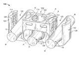
- FIG. 1is a perspective view of a spinal connector according to the present teachings, the spinal connector shown associated with two spinal connecting members;
- FIG. 2is a side view of the spinal connector of FIG. 1 ;
- FIG. 3is an end view of the spinal connector of FIG. 1 ;
- FIG. 4is a top view of the spinal connector of FIG. 1 ;
- FIG. 5is a bottom view of the spinal connector of FIG. 1 ;
- FIG. 6is a perspective view of a spinal connector according to the present teachings, the spinal connector shown associated with two spinal connecting members;
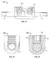
- FIG. 7is a sectional view of the spinal connector of FIG. 6 , taken along line 7 - 7 of FIG. 6 , the spinal connector shown associated with a locking element;
- FIG. 8is a sectional view of the spinal connector of FIG. 6 , taken along line 8 - 8 of FIG. 6 ;
- FIG. 9is a top view of the spinal connector of FIG. 6 ;
- FIG. 10is a bottom view of the spinal connector of FIG. 6 ;
- FIG. 11is a perspective view of a spinal connector according to the present teachings, the spinal connector shown associated with three spinal connecting members;
- FIG. 12is a perspective view of a spinal connector according to the present teachings, the spinal connector shown associated with two spinal connecting members;
- FIG. 13is a top view of the spinal connector of FIG. 12 ;
- FIG. 14is a side view of the spinal connector of FIG. 12 ;
- FIG. 15is an end view of the spinal connector of FIG. 12 ;
- FIG. 16is a sectional view of the spinal connector of FIG. 12 , taken along line 16 - 16 of FIG. 13 ;
- FIG. 17is a perspective view of a spinal connector according to the present teachings, the spinal connector shown associated with two spinal connecting members;
- FIG. 18is a top view of the spinal connector of FIG. 17 ;
- FIG. 19is an end view of the spinal connector of FIG. 17 ;
- FIG. 20is a side view of the spinal connector of FIG. 17 .
- the present teachingsprovide a spinal connector 100 that can be used to interconnect two or more elongated spinal connecting members 10 , such as connecting rods for the spine, for example.
- the spinal connecting members 10can have circular, or oval or elliptical or polygonal or otherwise shaped cross-sections with different diameters or widths.
- the spinal connector 100can connect two or more connecting members 10 side by side or next to each other, as illustrated in FIGS. 1 , 11 and 17 , for example.
- the spinal connector 100can also be used to connect two connecting members 10 end to end, as illustrated in FIGS. 6 and 12 , for example.
- the spinal connector 100can also be used to connect three or more connecting members 10 side by side, as illustrated in FIG. 11 for three connecting members 10 .
- the spinal connector 100can also connect at least three connecting members 10 in a combination of side by side and end to end orientations.
- the spinal connector 100 of FIG. 1can be combined with the spinal connector 100 of FIG. 6 or with the spinal connector 100 of FIG. 12 to provide a spinal connector 100 that includes first and second connecting members 10 arranged end to end, and at least one other (third) connecting member 10 arranged side by side relative to the first and second connecting members 10 .
- the spinal connectors 100 illustrated hereinare only representative of the present teachings.
- Various features of the spinal connectors 100 illustrated in FIGS. 1-20can be selectively combined to provide different spinal connectors 100 for connecting two or more connecting members 10 in various spatial relationships to each other, including side by side, end to end, and combinations thereof, as well as with different and/or variable and polyaxial orientations relative to each other.
- exemplary spinal connectors 100can be used to connect first and second connecting members 10 side by side.
- the spinal connector 100can provide polyaxial support for at least one of the connecting members 10 , such that the relative orientation of the connecting members 10 can vary, as illustrated in FIG. 1 .
- the first connecting member 10can be oriented along a first longitudinal axis A that can have variable orientation relative the fixed orientation of the second connecting member 10 , which is oriented along a fixed longitudinal axis B.
- the spinal connector 100can also provide polyaxial support for both the first and second connecting members 10 .
- the spinal connector 100can provide a fixed orientation of the respective first and second axes A and B of the first and second connecting members 10 in a side by side configuration, as illustrated in FIG. 17 .
- the connecting members 10are shown as being substantially parallel, it will be appreciated that the spinal connector 100 can support the connecting members 10 at other fixed angles defined by a fixed angle between the axes A and B.
- exemplary spinal connectors 100can be used to connect first and second connecting members 10 in end to end configurations.
- the spinal connector 100can provide polyaxial support for at least one of the first and second connecting members 10 , such that the relative orientation of the first and second longitudinal axes A and B of the respective first and second connecting members 10 can vary, as illustrated in FIG. 6 .
- the spinal connector 100can also provide polyaxial support for both the first and second connecting members 10 .
- the spinal connector 100can provide a fixed orientation of the respective first and second axes A and B of the first and second connecting members 10 in an end to end configuration, as illustrated in FIG. 12 .
- the connecting members 10are shown as being substantially coaxial, it will be appreciated that the spinal connector 100 can be angled such that the spinal connector 100 can support the connecting members 10 at other fixed angles defined by a fixed angle between the axes A and B.
- an exemplary spinal connector 100 for connecting three connecting members 10is illustrated.
- the spinal connector 100as illustrated in FIG. 11 , is symmetric and provides support along fixed axes B for two end connecting members 10 and polyaxial support along variable axis A for the center connecting member 10 , it will be appreciated that all other possible combinations of supporting three connecting members 10 are within the scope of the present teachings.
- the spinal connector 100 of FIG. 11can be either non-symmetric or symmetric.
- the spinal connector 100can provide polyaxial support for the center connecting member 10 and only one of the two end connecting members 10 , or provide polyaxial support of only one of the end connecting members 10 , or provide polyaxial support for both end connecting members 10 , but not for the center connecting member 10 .
- other connecting members 10can be supported either in side by side or end to end configurations relative to the existing connecting members 10 , as discussed above.
- the spinal connector 100can include two or more seats 101 for supporting a corresponding number of connecting members 10 , as illustrated, for example in FIG. 1 .
- Each seat 101can be of the fixed orientation type 102 or the polyaxial orientation type 104 .
- the seat of the fixed orientation type or fixed-support seat 102can support a connecting member 10 along axis B having a fixed orientation relative to the spinal connector 100 .
- the fixed-support seat 102can include a substantially V-shaped bottom surface 112 that can provide multiple-point contact with the corresponding connecting member 10 along straight contact lines, as shown in FIG. 2 , for example.
- the bottom surface 112 of the fixed-support seat 102can be substantially U-shaped and substantially conform to a portion of the outer cylindrical surface of the connecting member 10 .
- the fixed-support seat 102can be saddle-shaped having two upright arms 126 that define an opening 120 for receiving a corresponding connecting member 10 .
- the arms 126can include engagement formations 114 for engaging a locking element 150 , such as a set screw, for example, that can be used to secure the connecting member 10 on the seat 101 , as shown in FIGS. 7 , 12 and 17 , for example.
- the locking element 150can include corresponding engagement formations 152 that can mate with the engagement formations 114 of the corresponding seat 101 .
- the engagement formations 114can be provided in any of various thread designs, including, for example, helical flange, buttress thread, reverse buttress thread and standard thread.
- the open configuration of the fixed-support seat 102allows the connecting member 10 to be received in the fixed-support seat either before or after the connecting member 10 is already locked between two pedicle screws.
- the polyaxial support seat 104can include a substantially spherically shaped bottom surface 110 that can receive a coupling element 108 in the form of a ball enclosure having an outer spherical surface 130 mateable with the bottom surface 110 for polyaxial articulation therebetween, as shown, for example, in FIGS. 6-8 .
- the coupling element 108can have an inner bore 132 of substantially cylindrical shape that substantially matches the cross-sectional shape of the connecting member 10 , as shown in FIG. 7 .
- the connecting member 10can be slidably received in the bore 132 .
- the coupling element 108can include one or more slits 109 that can contribute to the resiliency of the coupling element 108 for better clamping on the connecting member 10 .
- the polyaxial seat 104can include an upper peripheral wall 124 defining an upper opening 122 , which can be peripherally fully enclosed, such that the connecting member 10 can be loaded in the polyaxial seat 104 from the end of the connecting member 10 .
- the upper opening 122 of the polyaxial seat 104can include engagement formations 114 mateable with a corresponding locking element 150 .
- the locking element 150can include a blind driver bore 154 for receiving a driver (not shown). The locking element 150 can be driven along the bore 122 of the polyaxial seat 104 for pressing on the coupling element 108 and securing the corresponding connecting member 10 .
- the spinal connector 100can include two or more seats 101 that have different cross-sectional sizes or widths and can accommodate connecting members 10 having different cross-sectional diameter or size or widths, as shown, for example, in FIG. 20 for two seats 101 of the fixed-support type 102 , although all the spinal connectors 100 , including those shown in FIGS. 1 , 6 , 11 , and 12 can include seats 101 for different size connecting members 10 .
- the spinal connector 100can include at least two seats 101 of the fixed-support type 102 , each with a substantially V-shaped bottom surface 112 for coupling corresponding connecting members 10 in fixed orientations relative to one another side by side, or end to end, or in combinations thereof.
- the spinal connectors 100can be made of any biocompatible materials, including metals, such as titanium, alloys or polymeric materials.
- the connecting members 10can be made of various materials, including for example, PEEK, titanium, stainless steel and other biocompatible materials, or combinations thereof.
Landscapes
- Health & Medical Sciences (AREA)
- Orthopedic Medicine & Surgery (AREA)
- Life Sciences & Earth Sciences (AREA)
- Neurology (AREA)
- Surgery (AREA)
- Heart & Thoracic Surgery (AREA)
- Engineering & Computer Science (AREA)
- Biomedical Technology (AREA)
- Nuclear Medicine, Radiotherapy & Molecular Imaging (AREA)
- Medical Informatics (AREA)
- Molecular Biology (AREA)
- Animal Behavior & Ethology (AREA)
- General Health & Medical Sciences (AREA)
- Public Health (AREA)
- Veterinary Medicine (AREA)
- Surgical Instruments (AREA)
- Prostheses (AREA)
Abstract
Description
Claims (24)
Priority Applications (3)
| Application Number | Priority Date | Filing Date | Title |
|---|---|---|---|
| US12/099,227US8337527B2 (en) | 2007-04-18 | 2008-04-08 | Spinal connector |
| AT08154821TATE512633T1 (en) | 2007-04-18 | 2008-04-18 | SPINAL CONNECTING ELEMENT |
| EP08154821AEP1982663B1 (en) | 2007-04-18 | 2008-04-18 | Spinal connector |
Applications Claiming Priority (2)
| Application Number | Priority Date | Filing Date | Title |
|---|---|---|---|
| US91249307P | 2007-04-18 | 2007-04-18 | |
| US12/099,227US8337527B2 (en) | 2007-04-18 | 2008-04-08 | Spinal connector |
Publications (2)
| Publication Number | Publication Date |
|---|---|
| US20080262553A1 US20080262553A1 (en) | 2008-10-23 |
| US8337527B2true US8337527B2 (en) | 2012-12-25 |
Family
ID=39639577
Family Applications (1)
| Application Number | Title | Priority Date | Filing Date |
|---|---|---|---|
| US12/099,227Active2031-05-03US8337527B2 (en) | 2007-04-18 | 2008-04-08 | Spinal connector |
Country Status (3)
| Country | Link |
|---|---|
| US (1) | US8337527B2 (en) |
| EP (1) | EP1982663B1 (en) |
| AT (1) | ATE512633T1 (en) |
Cited By (27)
| Publication number | Priority date | Publication date | Assignee | Title |
|---|---|---|---|---|
| US20100234892A1 (en)* | 2008-10-15 | 2010-09-16 | Keyvan Mazda | Spinal interconnecting device and a stabilizing system using said device |
| US20110087287A1 (en)* | 2009-10-09 | 2011-04-14 | Custom Spine, Inc. | Rod-to-Rod Connector |
| US8758411B1 (en) | 2011-10-25 | 2014-06-24 | Nuvasive, Inc. | Implants and methods for treating spinal disorders |
| US8992579B1 (en)* | 2011-03-08 | 2015-03-31 | Nuvasive, Inc. | Lateral fixation constructs and related methods |
| US9060815B1 (en) | 2012-03-08 | 2015-06-23 | Nuvasive, Inc. | Systems and methods for performing spine surgery |
| US20150272626A1 (en)* | 2013-03-14 | 2015-10-01 | Medos International Sarl | Bottom-loading bone anchor assemblies |
| US20160135846A1 (en)* | 2014-11-14 | 2016-05-19 | Warsaw Orthopedic, Inc. | Spinal implant system and method |
| US9517089B1 (en) | 2013-10-08 | 2016-12-13 | Nuvasive, Inc. | Bone anchor with offset rod connector |
| US9579126B2 (en) | 2008-02-02 | 2017-02-28 | Globus Medical, Inc. | Spinal rod link reducer |
| US9980755B2 (en) | 2016-03-29 | 2018-05-29 | Globus Medical, Inc. | Revision connectors, systems, and methods thereof |
| US10238432B2 (en) | 2017-02-10 | 2019-03-26 | Medos International Sàrl | Tandem rod connectors and related methods |
| US10307185B2 (en) | 2016-03-29 | 2019-06-04 | Globus Medical, Inc. | Revision connectors, systems, and methods thereof |
| US10321939B2 (en) | 2016-05-18 | 2019-06-18 | Medos International Sarl | Implant connectors and related methods |
| US10383663B2 (en) | 2016-03-29 | 2019-08-20 | Globus Medical, Inc. | Revision connectors, systems and methods thereof |
| US10398476B2 (en) | 2016-12-13 | 2019-09-03 | Medos International Sàrl | Implant adapters and related methods |
| US10492835B2 (en) | 2016-12-19 | 2019-12-03 | Medos International Sàrl | Offset rods, offset rod connectors, and related methods |
| US10517647B2 (en) | 2016-05-18 | 2019-12-31 | Medos International Sarl | Implant connectors and related methods |
| US10561454B2 (en) | 2017-03-28 | 2020-02-18 | Medos International Sarl | Articulating implant connectors and related methods |
| US10624679B2 (en) | 2016-03-29 | 2020-04-21 | Globus Medical, Inc. | Revision connectors, systems and methods thereof |
| US10966761B2 (en) | 2017-03-28 | 2021-04-06 | Medos International Sarl | Articulating implant connectors and related methods |
| US10966762B2 (en) | 2017-12-15 | 2021-04-06 | Medos International Sarl | Unilateral implant holders and related methods |
| US11076890B2 (en) | 2017-12-01 | 2021-08-03 | Medos International Sàrl | Rod-to-rod connectors having robust rod closure mechanisms and related methods |
| US11291481B2 (en) | 2019-03-21 | 2022-04-05 | Medos International Sarl | Rod reducers and related methods |
| US11291482B2 (en) | 2019-03-21 | 2022-04-05 | Medos International Sarl | Rod reducers and related methods |
| US11337734B2 (en) | 2019-05-22 | 2022-05-24 | Nuvasive, Inc. | Posterior spinal fixation screws |
| USD1004774S1 (en) | 2019-03-21 | 2023-11-14 | Medos International Sarl | Kerrison rod reducer |
| US12318121B2 (en) | 2020-11-09 | 2025-06-03 | Medos International Sàrl | Biplanar forceps reducers and methods of use |
Families Citing this family (45)
| Publication number | Priority date | Publication date | Assignee | Title |
|---|---|---|---|---|
| US7862587B2 (en) | 2004-02-27 | 2011-01-04 | Jackson Roger P | Dynamic stabilization assemblies, tool set and method |
| US10258382B2 (en) | 2007-01-18 | 2019-04-16 | Roger P. Jackson | Rod-cord dynamic connection assemblies with slidable bone anchor attachment members along the cord |
| US10729469B2 (en) | 2006-01-09 | 2020-08-04 | Roger P. Jackson | Flexible spinal stabilization assembly with spacer having off-axis core member |
| US11241261B2 (en) | 2005-09-30 | 2022-02-08 | Roger P Jackson | Apparatus and method for soft spinal stabilization using a tensionable cord and releasable end structure |
| US7901437B2 (en) | 2007-01-26 | 2011-03-08 | Jackson Roger P | Dynamic stabilization member with molded connection |
| US8100946B2 (en) | 2005-11-21 | 2012-01-24 | Synthes Usa, Llc | Polyaxial bone anchors with increased angulation |
| US8398637B2 (en)* | 2006-11-06 | 2013-03-19 | Douglas Eric Parsell | Device and method for less invasive surgical stabilization of pelvic fractures |
| US11224463B2 (en) | 2007-01-18 | 2022-01-18 | Roger P. Jackson | Dynamic stabilization connecting member with pre-tensioned flexible core member |
| US8475498B2 (en) | 2007-01-18 | 2013-07-02 | Roger P. Jackson | Dynamic stabilization connecting member with cord connection |
| US10383660B2 (en)* | 2007-05-01 | 2019-08-20 | Roger P. Jackson | Soft stabilization assemblies with pretensioned cords |
| US9439681B2 (en) | 2007-07-20 | 2016-09-13 | DePuy Synthes Products, Inc. | Polyaxial bone fixation element |
| US20090105756A1 (en) | 2007-10-23 | 2009-04-23 | Marc Richelsoph | Spinal implant |
| JP2009207877A (en)* | 2008-02-07 | 2009-09-17 | Showa Ika Kohgyo Co Ltd | Rod connector |
| AU2010260521C1 (en) | 2008-08-01 | 2013-08-01 | Roger P. Jackson | Longitudinal connecting member with sleeved tensioned cords |
| WO2010017471A1 (en)* | 2008-08-07 | 2010-02-11 | The Children's Mercy Hospital | Sliding rod system for correcting spinal deformities |
| EP2484300B1 (en)* | 2008-09-05 | 2015-05-20 | Biedermann Technologies GmbH & Co. KG | Stabilization device for bones, in particular for the spinal column |
| US9603629B2 (en)* | 2008-09-09 | 2017-03-28 | Intelligent Implant Systems Llc | Polyaxial screw assembly |
| JP5815407B2 (en) | 2008-09-12 | 2015-11-17 | ジンテス ゲゼルシャフト ミット ベシュレンクテル ハフツング | Spinal stabilization and guided fixation system |
| KR20110081208A (en) | 2008-09-29 | 2011-07-13 | 신세스 게엠바하 | Multi-Axis Bottom-Loading Screw and Rod Assemblies |
| CA2742399A1 (en) | 2008-11-03 | 2010-06-03 | Dustin M. Harvey | Uni-planar bone fixation assembly |
| GB2465156B (en) | 2008-11-05 | 2012-09-26 | Dalmatic Lystrup As | Bone fixation system |
| GB2465335B (en) | 2008-11-05 | 2012-08-15 | Dalmatic Lystrup As | Bone fixation device |
| US8828058B2 (en)* | 2008-11-11 | 2014-09-09 | Kspine, Inc. | Growth directed vertebral fixation system with distractible connector(s) and apical control |
| US8998961B1 (en)* | 2009-02-26 | 2015-04-07 | Lanx, Inc. | Spinal rod connector and methods |
| US9351767B2 (en)* | 2009-03-24 | 2016-05-31 | Life Spine, Inc. | Supplementary spinal fixation/stabilization apparatus with dynamic inter-vertebral connection |
| US8882803B2 (en) | 2009-04-01 | 2014-11-11 | Globus Medical, Inc. | Orthopedic clamp and extension rod |
| KR20120013312A (en) | 2009-04-15 | 2012-02-14 | 신세스 게엠바하 | Orthodontic Connectors for Spinal Structures |
| US9668771B2 (en) | 2009-06-15 | 2017-06-06 | Roger P Jackson | Soft stabilization assemblies with off-set connector |
| CA2764841A1 (en)* | 2009-06-17 | 2010-12-23 | Synthes Usa, Llc | Revision connector for spinal constructs |
| AU2011299558A1 (en) | 2010-09-08 | 2013-05-02 | Roger P. Jackson | Dynamic stabilization members with elastic and inelastic sections |
| EP2468200A1 (en) | 2010-12-21 | 2012-06-27 | Zimmer Spine | Orthopaedic device and methods for its pre-assembly and assembly |
| EP2505154A1 (en)* | 2011-03-31 | 2012-10-03 | Spinelab AG | Spinal implant |
| EP2505155A1 (en)* | 2011-03-31 | 2012-10-03 | Spinelab AG | Spinal implant for stabilising and reinforcing spinal bodies of a spine |
| FR2976783B1 (en)* | 2011-06-22 | 2014-05-09 | Medicrea International | MATERIAL OF VERTEBRAL OSTEOSYNTHESIS |
| US9649136B2 (en)* | 2011-07-15 | 2017-05-16 | Globus Medical, Inc. | Coupling devices and methods of using the same |
| EP2662037B1 (en)* | 2012-05-09 | 2023-01-11 | CoLigne AG | Iliac connector, connector head and spinal fixation system |
| US9237907B2 (en) | 2013-03-05 | 2016-01-19 | Warsaw Orthopedic, Inc. | Spinal correction system and method |
| US9044273B2 (en) | 2013-10-07 | 2015-06-02 | Intelligent Implant Systems, Llc | Polyaxial plate rod system and surgical procedure |
| US20180228516A1 (en)* | 2017-02-14 | 2018-08-16 | Warsaw Orthopedic, Inc. | Spinal implant system and method |
| US20180243012A1 (en)* | 2017-02-24 | 2018-08-30 | Warsaw Orthopedic, Inc | Spinal implant system and method |
| US11864801B2 (en)* | 2019-07-31 | 2024-01-09 | Seaspine, Inc. | Implantable universal connector |
| US11311317B2 (en)* | 2019-09-25 | 2022-04-26 | Stelios KOUTSOUMBELIS | Spinal fixation device with rotatable connector |
| WO2021144636A1 (en)* | 2020-01-19 | 2021-07-22 | Inno4Spine Ag | Connector implant for extending a spinal construct |
| CA3166858A1 (en) | 2020-01-28 | 2021-08-05 | Orthopediatrics Corp. | Spinal rod-to-rod connectors |
| DE102020108276A1 (en)* | 2020-03-25 | 2021-09-30 | Aesculap Ag | Surgical connector and surgical connector system |
Citations (16)
| Publication number | Priority date | Publication date | Assignee | Title |
|---|---|---|---|---|
| US5133717A (en) | 1990-02-08 | 1992-07-28 | Societe De Fabrication De Material Orthopedique Sofamor | Sacral support saddle for a spinal osteosynthesis device |
| US5910142A (en) | 1998-10-19 | 1999-06-08 | Bones Consulting, Llc | Polyaxial pedicle screw having a rod clamping split ferrule coupling element |
| US5993449A (en) | 1995-11-30 | 1999-11-30 | Synthes (Usa) | Bone-fixing device |
| US20030032959A1 (en)* | 1999-12-10 | 2003-02-13 | Chung-Chun Yeh | Spinal fixation hook and spinal fixation retrieval device |
| US20030229345A1 (en)* | 2002-06-11 | 2003-12-11 | Stahurski Terrence M. | Connector assembly with multidimensional accommodation and associated method |
| US6749612B1 (en) | 1998-10-09 | 2004-06-15 | Stryker Spine | Spinal osteosynthesis system with improved rigidity |
| US20050154388A1 (en) | 2002-01-31 | 2005-07-14 | Pierre Roussouly | Spinal osteosynthesis connector and instrumentation |
| US20050192572A1 (en)* | 2004-02-27 | 2005-09-01 | Custom Spine, Inc. | Medialised rod pedicle screw assembly |
| US20050228378A1 (en)* | 2004-03-31 | 2005-10-13 | Iain Kalfas | Spinal rod connector |
| US6960212B2 (en) | 2001-02-12 | 2005-11-01 | Aesculap Ii, Inc. | Rod to rod connector |
| US20050277932A1 (en)* | 2004-06-15 | 2005-12-15 | Sdgi Holdings, Inc. | Spinal rod system |
| US20050277928A1 (en) | 2004-06-14 | 2005-12-15 | Boschert Paul F | Spinal implant fixation assembly |
| US20060089644A1 (en)* | 2004-10-27 | 2006-04-27 | Felix Brent A | Spinal stabilizing system |
| US20060247626A1 (en)* | 2005-04-29 | 2006-11-02 | Sdgi Holdings, Inc. | Device for interconnecting components in spinal instrumentation |
| US7175522B2 (en) | 2001-03-22 | 2007-02-13 | Shuffle Master, Inc. | Combination wagering game |
| US7575587B2 (en)* | 2005-12-30 | 2009-08-18 | Warsaw Orthopedic, Inc. | Top-tightening side-locking spinal connector assembly |
Family Cites Families (5)
| Publication number | Priority date | Publication date | Assignee | Title |
|---|---|---|---|---|
| US8187303B2 (en)* | 2004-04-22 | 2012-05-29 | Gmedelaware 2 Llc | Anti-rotation fixation element for spinal prostheses |
| US8512380B2 (en)* | 2002-08-28 | 2013-08-20 | Warsaw Orthopedic, Inc. | Posterior fixation system |
| US20030114853A1 (en)* | 2001-10-12 | 2003-06-19 | Ian Burgess | Polyaxial cross connector |
| US8029543B2 (en)* | 2002-10-28 | 2011-10-04 | Warsaw Othopedic, Inc. | Multi-axial, cross-link connector system for spinal implants |
| CA2694010C (en)* | 2007-07-19 | 2015-04-21 | Synthes Usa, Llc | Clamps used for interconnecting a bone anchor to a rod |
- 2008
- 2008-04-08USUS12/099,227patent/US8337527B2/enactiveActive
- 2008-04-18EPEP08154821Apatent/EP1982663B1/ennot_activeNot-in-force
- 2008-04-18ATAT08154821Tpatent/ATE512633T1/ennot_activeIP Right Cessation
Patent Citations (17)
| Publication number | Priority date | Publication date | Assignee | Title |
|---|---|---|---|---|
| US5133717A (en) | 1990-02-08 | 1992-07-28 | Societe De Fabrication De Material Orthopedique Sofamor | Sacral support saddle for a spinal osteosynthesis device |
| US5993449A (en) | 1995-11-30 | 1999-11-30 | Synthes (Usa) | Bone-fixing device |
| US6749612B1 (en) | 1998-10-09 | 2004-06-15 | Stryker Spine | Spinal osteosynthesis system with improved rigidity |
| US5910142A (en) | 1998-10-19 | 1999-06-08 | Bones Consulting, Llc | Polyaxial pedicle screw having a rod clamping split ferrule coupling element |
| US20030032959A1 (en)* | 1999-12-10 | 2003-02-13 | Chung-Chun Yeh | Spinal fixation hook and spinal fixation retrieval device |
| US6960212B2 (en) | 2001-02-12 | 2005-11-01 | Aesculap Ii, Inc. | Rod to rod connector |
| US7175522B2 (en) | 2001-03-22 | 2007-02-13 | Shuffle Master, Inc. | Combination wagering game |
| US20050154388A1 (en) | 2002-01-31 | 2005-07-14 | Pierre Roussouly | Spinal osteosynthesis connector and instrumentation |
| US20030229345A1 (en)* | 2002-06-11 | 2003-12-11 | Stahurski Terrence M. | Connector assembly with multidimensional accommodation and associated method |
| US20050192572A1 (en)* | 2004-02-27 | 2005-09-01 | Custom Spine, Inc. | Medialised rod pedicle screw assembly |
| US20050228378A1 (en)* | 2004-03-31 | 2005-10-13 | Iain Kalfas | Spinal rod connector |
| WO2005099603A1 (en) | 2004-03-31 | 2005-10-27 | Depuy Spine Sarl | Spinal rod connector |
| US20050277928A1 (en) | 2004-06-14 | 2005-12-15 | Boschert Paul F | Spinal implant fixation assembly |
| US20050277932A1 (en)* | 2004-06-15 | 2005-12-15 | Sdgi Holdings, Inc. | Spinal rod system |
| US20060089644A1 (en)* | 2004-10-27 | 2006-04-27 | Felix Brent A | Spinal stabilizing system |
| US20060247626A1 (en)* | 2005-04-29 | 2006-11-02 | Sdgi Holdings, Inc. | Device for interconnecting components in spinal instrumentation |
| US7575587B2 (en)* | 2005-12-30 | 2009-08-18 | Warsaw Orthopedic, Inc. | Top-tightening side-locking spinal connector assembly |
Non-Patent Citations (1)
| Title |
|---|
| Extended European Search Report on European Patent Application No. EP 08 15 4821 mailed Feb. 27, 2008. |
Cited By (48)
| Publication number | Priority date | Publication date | Assignee | Title |
|---|---|---|---|---|
| US9579126B2 (en) | 2008-02-02 | 2017-02-28 | Globus Medical, Inc. | Spinal rod link reducer |
| US20100234892A1 (en)* | 2008-10-15 | 2010-09-16 | Keyvan Mazda | Spinal interconnecting device and a stabilizing system using said device |
| US20110087287A1 (en)* | 2009-10-09 | 2011-04-14 | Custom Spine, Inc. | Rod-to-Rod Connector |
| US8992579B1 (en)* | 2011-03-08 | 2015-03-31 | Nuvasive, Inc. | Lateral fixation constructs and related methods |
| US8758411B1 (en) | 2011-10-25 | 2014-06-24 | Nuvasive, Inc. | Implants and methods for treating spinal disorders |
| US9060815B1 (en) | 2012-03-08 | 2015-06-23 | Nuvasive, Inc. | Systems and methods for performing spine surgery |
| US9579131B1 (en) | 2012-03-08 | 2017-02-28 | Nuvasive, Inc. | Systems and methods for performing spine surgery |
| US20150272626A1 (en)* | 2013-03-14 | 2015-10-01 | Medos International Sarl | Bottom-loading bone anchor assemblies |
| US9498254B2 (en)* | 2013-03-14 | 2016-11-22 | Medos International Sarl | Bottom-loading bone anchor assemblies |
| US9517089B1 (en) | 2013-10-08 | 2016-12-13 | Nuvasive, Inc. | Bone anchor with offset rod connector |
| US20160135846A1 (en)* | 2014-11-14 | 2016-05-19 | Warsaw Orthopedic, Inc. | Spinal implant system and method |
| US9763695B2 (en)* | 2014-11-14 | 2017-09-19 | Warsaw Orthopedic, Inc. | Spinal implant system and method |
| US10874440B2 (en) | 2016-03-29 | 2020-12-29 | Globus Medical, Inc. | Revision connectors, systems and methods thereof |
| US10624679B2 (en) | 2016-03-29 | 2020-04-21 | Globus Medical, Inc. | Revision connectors, systems and methods thereof |
| US10307185B2 (en) | 2016-03-29 | 2019-06-04 | Globus Medical, Inc. | Revision connectors, systems, and methods thereof |
| US11723693B2 (en) | 2016-03-29 | 2023-08-15 | Globus Medical, Inc. | Revision connectors, systems and methods thereof |
| US10383663B2 (en) | 2016-03-29 | 2019-08-20 | Globus Medical, Inc. | Revision connectors, systems and methods thereof |
| US11534209B2 (en) | 2016-03-29 | 2022-12-27 | Globus Medical, Inc. | Revision connectors, systems and methods thereof |
| US10905471B2 (en) | 2016-03-29 | 2021-02-02 | Globus Medical, Inc. | Revision connectors, systems and methods thereof |
| US9980755B2 (en) | 2016-03-29 | 2018-05-29 | Globus Medical, Inc. | Revision connectors, systems, and methods thereof |
| US10820929B2 (en) | 2016-03-29 | 2020-11-03 | Globus Medical Inc. | Revision connectors, systems, and methods thereof |
| US11596451B2 (en) | 2016-05-18 | 2023-03-07 | Medos International Sarl | Implant connectors and related methods |
| US10321939B2 (en) | 2016-05-18 | 2019-06-18 | Medos International Sarl | Implant connectors and related methods |
| US11058463B2 (en) | 2016-05-18 | 2021-07-13 | Medos International Sarl | Implant connectors and related methods |
| US10517647B2 (en) | 2016-05-18 | 2019-12-31 | Medos International Sarl | Implant connectors and related methods |
| US10398476B2 (en) | 2016-12-13 | 2019-09-03 | Medos International Sàrl | Implant adapters and related methods |
| US11160583B2 (en) | 2016-12-19 | 2021-11-02 | Medos International Sarl | Offset rods, offset rod connectors, and related methods |
| US12150679B2 (en) | 2016-12-19 | 2024-11-26 | Medos International Srl | Offset rods, offset rod connectors, and related methods |
| US10492835B2 (en) | 2016-12-19 | 2019-12-03 | Medos International Sàrl | Offset rods, offset rod connectors, and related methods |
| US10869695B2 (en) | 2017-02-10 | 2020-12-22 | Medos International Sarl | Tandem rod connectors and related methods |
| US10238432B2 (en) | 2017-02-10 | 2019-03-26 | Medos International Sàrl | Tandem rod connectors and related methods |
| US11793554B2 (en) | 2017-02-10 | 2023-10-24 | Medos International Sarl | Tandem rod connectors and related methods |
| US12059187B2 (en) | 2017-03-28 | 2024-08-13 | Medos International Sarl | Articulating implant connectors and related methods |
| US11382676B2 (en) | 2017-03-28 | 2022-07-12 | Medos International Sarl | Articulating implant connectors and related methods |
| US10966761B2 (en) | 2017-03-28 | 2021-04-06 | Medos International Sarl | Articulating implant connectors and related methods |
| US11707304B2 (en) | 2017-03-28 | 2023-07-25 | Medos International Sarl | Articulating implant connectors and related methods |
| US10561454B2 (en) | 2017-03-28 | 2020-02-18 | Medos International Sarl | Articulating implant connectors and related methods |
| US11076890B2 (en) | 2017-12-01 | 2021-08-03 | Medos International Sàrl | Rod-to-rod connectors having robust rod closure mechanisms and related methods |
| US12336742B2 (en) | 2017-12-15 | 2025-06-24 | Medos International Sárl | Unilateral implant holders and related methods |
| US11832855B2 (en) | 2017-12-15 | 2023-12-05 | Medos International Sårl | Unilateral implant holders and related methods |
| US10966762B2 (en) | 2017-12-15 | 2021-04-06 | Medos International Sarl | Unilateral implant holders and related methods |
| US11291482B2 (en) | 2019-03-21 | 2022-04-05 | Medos International Sarl | Rod reducers and related methods |
| USD1004774S1 (en) | 2019-03-21 | 2023-11-14 | Medos International Sarl | Kerrison rod reducer |
| US11291481B2 (en) | 2019-03-21 | 2022-04-05 | Medos International Sarl | Rod reducers and related methods |
| US11684395B2 (en) | 2019-05-22 | 2023-06-27 | Nuvasive, Inc. | Posterior spinal fixation screws |
| US11337734B2 (en) | 2019-05-22 | 2022-05-24 | Nuvasive, Inc. | Posterior spinal fixation screws |
| US11571244B2 (en) | 2019-05-22 | 2023-02-07 | Nuvasive, Inc. | Posterior spinal fixation screws |
| US12318121B2 (en) | 2020-11-09 | 2025-06-03 | Medos International Sàrl | Biplanar forceps reducers and methods of use |
Also Published As
| Publication number | Publication date |
|---|---|
| ATE512633T1 (en) | 2011-07-15 |
| EP1982663A2 (en) | 2008-10-22 |
| US20080262553A1 (en) | 2008-10-23 |
| EP1982663B1 (en) | 2011-06-15 |
| EP1982663A3 (en) | 2009-04-01 |
Similar Documents
| Publication | Publication Date | Title |
|---|---|---|
| US8337527B2 (en) | Spinal connector | |
| US20240268867A1 (en) | Receiving part for receiving a rod for coupling the rod to a bone anchoring element | |
| US8771319B2 (en) | Rod to rod cross connector | |
| EP1898819B1 (en) | Spinal construct system | |
| US9924974B2 (en) | Polyaxial bone anchoring device | |
| US9918748B2 (en) | Spinal rod connector | |
| EP2468199B1 (en) | Polyaxial bone anchoring device | |
| US8147523B2 (en) | Offset vertebral rod connector | |
| US7175622B2 (en) | Spinal rod system | |
| EP2457527B1 (en) | Polyaxial bone anchoring device with enlarged pivot angle | |
| US9095386B2 (en) | Spinal rod guide for a vertebral screw spinal rod connector assembly | |
| AU2002223744B2 (en) | Vertebral arthrodesis equipment | |
| WO2006119158A2 (en) | Spinal construct system | |
| JP2012521802A (en) | Variable height polyaxial bone screw assembly | |
| EP2720630A1 (en) | Modular bone plate and member of such a modular bone plate | |
| WO2010150140A1 (en) | Vertebral osteosynthesis equipment | |
| US11395684B2 (en) | Head to head cross connector |
Legal Events
| Date | Code | Title | Description |
|---|---|---|---|
| AS | Assignment | Owner name:EBI, LLC, NEW JERSEY Free format text:ASSIGNMENT OF ASSIGNORS INTEREST;ASSIGNORS:HAWKINS, NATHANIEL E.;BENDER, NICHOLAS J.;FERREIRA, RUI J.;REEL/FRAME:020770/0486;SIGNING DATES FROM 20080403 TO 20080408 Owner name:EBI, LLC, NEW JERSEY Free format text:ASSIGNMENT OF ASSIGNORS INTEREST;ASSIGNORS:HAWKINS, NATHANIEL E.;BENDER, NICHOLAS J.;FERREIRA, RUI J.;SIGNING DATES FROM 20080403 TO 20080408;REEL/FRAME:020770/0486 | |
| AS | Assignment | Owner name:BANK OF AMERICA, N.A., AS ADMINISTRATIVE AGENT FOR Free format text:SECURITY AGREEMENT;ASSIGNORS:LVB ACQUISITION, INC.;BIOMET, INC.;BIOMET 3I, LLC;AND OTHERS;REEL/FRAME:023505/0241 Effective date:20091111 | |
| STCF | Information on status: patent grant | Free format text:PATENTED CASE | |
| CC | Certificate of correction | ||
| CC | Certificate of correction | ||
| AS | Assignment | Owner name:CROSS MEDICAL PRODUCTS, LLC, CALIFORNIA Free format text:RELEASE OF SECURITY INTEREST IN PATENTS RECORDED AT REEL 023505/ FRAME 0241;ASSIGNOR:BANK OF AMERICA, N.A., AS ADMINISTRATIVE AGENT;REEL/FRAME:037155/0082 Effective date:20150624 Owner name:BIOMET TRAVEL, INC., INDIANA Free format text:RELEASE OF SECURITY INTEREST IN PATENTS RECORDED AT REEL 023505/ FRAME 0241;ASSIGNOR:BANK OF AMERICA, N.A., AS ADMINISTRATIVE AGENT;REEL/FRAME:037155/0082 Effective date:20150624 Owner name:BIOMET ORTHOPEDICS, LLC, INDIANA Free format text:RELEASE OF SECURITY INTEREST IN PATENTS RECORDED AT REEL 023505/ FRAME 0241;ASSIGNOR:BANK OF AMERICA, N.A., AS ADMINISTRATIVE AGENT;REEL/FRAME:037155/0082 Effective date:20150624 Owner name:BIOMET MICROFIXATION, LLC, FLORIDA Free format text:RELEASE OF SECURITY INTEREST IN PATENTS RECORDED AT REEL 023505/ FRAME 0241;ASSIGNOR:BANK OF AMERICA, N.A., AS ADMINISTRATIVE AGENT;REEL/FRAME:037155/0082 Effective date:20150624 Owner name:BIOMET INTERNATIONAL LTD., INDIANA Free format text:RELEASE OF SECURITY INTEREST IN PATENTS RECORDED AT REEL 023505/ FRAME 0241;ASSIGNOR:BANK OF AMERICA, N.A., AS ADMINISTRATIVE AGENT;REEL/FRAME:037155/0082 Effective date:20150624 Owner name:IMPLANT INNOVATIONS HOLDINGS, LLC, INDIANA Free format text:RELEASE OF SECURITY INTEREST IN PATENTS RECORDED AT REEL 023505/ FRAME 0241;ASSIGNOR:BANK OF AMERICA, N.A., AS ADMINISTRATIVE AGENT;REEL/FRAME:037155/0082 Effective date:20150624 Owner name:EBI HOLDINGS, LLC, INDIANA Free format text:RELEASE OF SECURITY INTEREST IN PATENTS RECORDED AT REEL 023505/ FRAME 0241;ASSIGNOR:BANK OF AMERICA, N.A., AS ADMINISTRATIVE AGENT;REEL/FRAME:037155/0082 Effective date:20150624 Owner name:BIOLECTRON, INC., INDIANA Free format text:RELEASE OF SECURITY INTEREST IN PATENTS RECORDED AT REEL 023505/ FRAME 0241;ASSIGNOR:BANK OF AMERICA, N.A., AS ADMINISTRATIVE AGENT;REEL/FRAME:037155/0082 Effective date:20150624 Owner name:INTERPORE SPINE, LTD., CALIFORNIA Free format text:RELEASE OF SECURITY INTEREST IN PATENTS RECORDED AT REEL 023505/ FRAME 0241;ASSIGNOR:BANK OF AMERICA, N.A., AS ADMINISTRATIVE AGENT;REEL/FRAME:037155/0082 Effective date:20150624 Owner name:INTERPORE CROSS INTERNATIONAL, LLC, CALIFORNIA Free format text:RELEASE OF SECURITY INTEREST IN PATENTS RECORDED AT REEL 023505/ FRAME 0241;ASSIGNOR:BANK OF AMERICA, N.A., AS ADMINISTRATIVE AGENT;REEL/FRAME:037155/0082 Effective date:20150624 Owner name:LVB ACQUISITION, INC., INDIANA Free format text:RELEASE OF SECURITY INTEREST IN PATENTS RECORDED AT REEL 023505/ FRAME 0241;ASSIGNOR:BANK OF AMERICA, N.A., AS ADMINISTRATIVE AGENT;REEL/FRAME:037155/0082 Effective date:20150624 Owner name:BIOMET SPORTS MEDICINE, LLC, INDIANA Free format text:RELEASE OF SECURITY INTEREST IN PATENTS RECORDED AT REEL 023505/ FRAME 0241;ASSIGNOR:BANK OF AMERICA, N.A., AS ADMINISTRATIVE AGENT;REEL/FRAME:037155/0082 Effective date:20150624 Owner name:BIOMET EUROPE LTD., INDIANA Free format text:RELEASE OF SECURITY INTEREST IN PATENTS RECORDED AT REEL 023505/ FRAME 0241;ASSIGNOR:BANK OF AMERICA, N.A., AS ADMINISTRATIVE AGENT;REEL/FRAME:037155/0082 Effective date:20150624 Owner name:ELECTR-OBIOLOGY, LLC, INDIANA Free format text:RELEASE OF SECURITY INTEREST IN PATENTS RECORDED AT REEL 023505/ FRAME 0241;ASSIGNOR:BANK OF AMERICA, N.A., AS ADMINISTRATIVE AGENT;REEL/FRAME:037155/0082 Effective date:20150624 Owner name:BIOMET LEASING, INC., INDIANA Free format text:RELEASE OF SECURITY INTEREST IN PATENTS RECORDED AT REEL 023505/ FRAME 0241;ASSIGNOR:BANK OF AMERICA, N.A., AS ADMINISTRATIVE AGENT;REEL/FRAME:037155/0082 Effective date:20150624 Owner name:KIRSCHNER MEDICAL CORPORATION, INDIANA Free format text:RELEASE OF SECURITY INTEREST IN PATENTS RECORDED AT REEL 023505/ FRAME 0241;ASSIGNOR:BANK OF AMERICA, N.A., AS ADMINISTRATIVE AGENT;REEL/FRAME:037155/0082 Effective date:20150624 Owner name:EBI, LLC, INDIANA Free format text:RELEASE OF SECURITY INTEREST IN PATENTS RECORDED AT REEL 023505/ FRAME 0241;ASSIGNOR:BANK OF AMERICA, N.A., AS ADMINISTRATIVE AGENT;REEL/FRAME:037155/0082 Effective date:20150624 Owner name:BIOMET MANUFACTURING CORPORATION, INDIANA Free format text:RELEASE OF SECURITY INTEREST IN PATENTS RECORDED AT REEL 023505/ FRAME 0241;ASSIGNOR:BANK OF AMERICA, N.A., AS ADMINISTRATIVE AGENT;REEL/FRAME:037155/0082 Effective date:20150624 Owner name:EBI MEDICAL SYSTEMS, LLC, INDIANA Free format text:RELEASE OF SECURITY INTEREST IN PATENTS RECORDED AT REEL 023505/ FRAME 0241;ASSIGNOR:BANK OF AMERICA, N.A., AS ADMINISTRATIVE AGENT;REEL/FRAME:037155/0082 Effective date:20150624 Owner name:BIOMET 3I, LLC, FLORIDA Free format text:RELEASE OF SECURITY INTEREST IN PATENTS RECORDED AT REEL 023505/ FRAME 0241;ASSIGNOR:BANK OF AMERICA, N.A., AS ADMINISTRATIVE AGENT;REEL/FRAME:037155/0082 Effective date:20150624 Owner name:BIOMET, INC., INDIANA Free format text:RELEASE OF SECURITY INTEREST IN PATENTS RECORDED AT REEL 023505/ FRAME 0241;ASSIGNOR:BANK OF AMERICA, N.A., AS ADMINISTRATIVE AGENT;REEL/FRAME:037155/0082 Effective date:20150624 Owner name:BIOMET BIOLOGICS, LLC., INDIANA Free format text:RELEASE OF SECURITY INTEREST IN PATENTS RECORDED AT REEL 023505/ FRAME 0241;ASSIGNOR:BANK OF AMERICA, N.A., AS ADMINISTRATIVE AGENT;REEL/FRAME:037155/0082 Effective date:20150624 Owner name:BIOMET FLORIDA SERVICES, LLC, INDIANA Free format text:RELEASE OF SECURITY INTEREST IN PATENTS RECORDED AT REEL 023505/ FRAME 0241;ASSIGNOR:BANK OF AMERICA, N.A., AS ADMINISTRATIVE AGENT;REEL/FRAME:037155/0082 Effective date:20150624 Owner name:BIOMET FAIR LAWN LLC, NEW JERSEY Free format text:RELEASE OF SECURITY INTEREST IN PATENTS RECORDED AT REEL 023505/ FRAME 0241;ASSIGNOR:BANK OF AMERICA, N.A., AS ADMINISTRATIVE AGENT;REEL/FRAME:037155/0082 Effective date:20150624 Owner name:BIOMET HOLDINGS LTD., INDIANA Free format text:RELEASE OF SECURITY INTEREST IN PATENTS RECORDED AT REEL 023505/ FRAME 0241;ASSIGNOR:BANK OF AMERICA, N.A., AS ADMINISTRATIVE AGENT;REEL/FRAME:037155/0082 Effective date:20150624 | |
| FPAY | Fee payment | Year of fee payment:4 | |
| AS | Assignment | Owner name:ZIMMER BIOMET SPINE, INC., COLORADO Free format text:ASSIGNMENT OF ASSIGNORS INTEREST;ASSIGNOR:EBI, LLC;REEL/FRAME:044712/0790 Effective date:20170621 | |
| MAFP | Maintenance fee payment | Free format text:PAYMENT OF MAINTENANCE FEE, 8TH YEAR, LARGE ENTITY (ORIGINAL EVENT CODE: M1552); ENTITY STATUS OF PATENT OWNER: LARGE ENTITY Year of fee payment:8 | |
| AS | Assignment | Owner name:CERBERUS BUSINESS FINANCE AGENCY, LLC, NEW YORK Free format text:GRANT OF A SECURITY INTEREST -- PATENTS;ASSIGNORS:ZIMMER BIOMET SPINE, LLC;EBI, LLC;REEL/FRAME:066970/0806 Effective date:20240401 | |
| MAFP | Maintenance fee payment | Free format text:PAYMENT OF MAINTENANCE FEE, 12TH YEAR, LARGE ENTITY (ORIGINAL EVENT CODE: M1553); ENTITY STATUS OF PATENT OWNER: LARGE ENTITY Year of fee payment:12 | |
| AS | Assignment | Owner name:ZIMMER BIOMET SPINE, LLC, COLORADO Free format text:CHANGE OF NAME;ASSIGNOR:ZIMMER BIOMET SPINE, INC.;REEL/FRAME:069772/0121 Effective date:20240220 Owner name:HIGHRIDGE MEDICAL, LLC, COLORADO Free format text:CHANGE OF NAME;ASSIGNOR:ZIMMER BIOMET SPINE, LLC;REEL/FRAME:069772/0248 Effective date:20240405 |