US8337523B2 - Tissue fixation assembly having prepositioned fasteners and method - Google Patents
Tissue fixation assembly having prepositioned fasteners and methodDownload PDFInfo
- Publication number
- US8337523B2 US8337523B2US12/460,247US46024709AUS8337523B2US 8337523 B2US8337523 B2US 8337523B2US 46024709 AUS46024709 AUS 46024709AUS 8337523 B2US8337523 B2US 8337523B2
- Authority
- US
- United States
- Prior art keywords
- fastener
- tissue
- deployment
- wire
- members
- Prior art date
- Legal status (The legal status is an assumption and is not a legal conclusion. Google has not performed a legal analysis and makes no representation as to the accuracy of the status listed.)
- Expired - Lifetime, expires
Links
Images


Classifications
- A—HUMAN NECESSITIES
- A61—MEDICAL OR VETERINARY SCIENCE; HYGIENE
- A61B—DIAGNOSIS; SURGERY; IDENTIFICATION
- A61B17/00—Surgical instruments, devices or methods
- A61B17/04—Surgical instruments, devices or methods for suturing wounds; Holders or packages for needles or suture materials
- A61B17/0401—Suture anchors, buttons or pledgets, i.e. means for attaching sutures to bone, cartilage or soft tissue; Instruments for applying or removing suture anchors
- A—HUMAN NECESSITIES
- A61—MEDICAL OR VETERINARY SCIENCE; HYGIENE
- A61B—DIAGNOSIS; SURGERY; IDENTIFICATION
- A61B17/00—Surgical instruments, devices or methods
- A61B17/04—Surgical instruments, devices or methods for suturing wounds; Holders or packages for needles or suture materials
- A61B17/0469—Suturing instruments for use in minimally invasive surgery, e.g. endoscopic surgery
- A—HUMAN NECESSITIES
- A61—MEDICAL OR VETERINARY SCIENCE; HYGIENE
- A61B—DIAGNOSIS; SURGERY; IDENTIFICATION
- A61B17/00—Surgical instruments, devices or methods
- A61B17/064—Surgical staples, i.e. penetrating the tissue
- A—HUMAN NECESSITIES
- A61—MEDICAL OR VETERINARY SCIENCE; HYGIENE
- A61B—DIAGNOSIS; SURGERY; IDENTIFICATION
- A61B17/00—Surgical instruments, devices or methods
- A61B17/068—Surgical staplers, e.g. containing multiple staples or clamps
- A—HUMAN NECESSITIES
- A61—MEDICAL OR VETERINARY SCIENCE; HYGIENE
- A61B—DIAGNOSIS; SURGERY; IDENTIFICATION
- A61B17/00—Surgical instruments, devices or methods
- A61B17/11—Surgical instruments, devices or methods for performing anastomosis; Buttons for anastomosis
- A61B17/1114—Surgical instruments, devices or methods for performing anastomosis; Buttons for anastomosis of the digestive tract, e.g. bowels or oesophagus
- A—HUMAN NECESSITIES
- A61—MEDICAL OR VETERINARY SCIENCE; HYGIENE
- A61B—DIAGNOSIS; SURGERY; IDENTIFICATION
- A61B17/00—Surgical instruments, devices or methods
- A61B2017/00743—Type of operation; Specification of treatment sites
- A61B2017/00818—Treatment of the gastro-intestinal system
- A61B2017/00827—Treatment of gastro-esophageal reflux
- A—HUMAN NECESSITIES
- A61—MEDICAL OR VETERINARY SCIENCE; HYGIENE
- A61B—DIAGNOSIS; SURGERY; IDENTIFICATION
- A61B17/00—Surgical instruments, devices or methods
- A61B17/04—Surgical instruments, devices or methods for suturing wounds; Holders or packages for needles or suture materials
- A61B17/0401—Suture anchors, buttons or pledgets, i.e. means for attaching sutures to bone, cartilage or soft tissue; Instruments for applying or removing suture anchors
- A61B2017/0409—Instruments for applying suture anchors
- A—HUMAN NECESSITIES
- A61—MEDICAL OR VETERINARY SCIENCE; HYGIENE
- A61B—DIAGNOSIS; SURGERY; IDENTIFICATION
- A61B17/00—Surgical instruments, devices or methods
- A61B17/04—Surgical instruments, devices or methods for suturing wounds; Holders or packages for needles or suture materials
- A61B17/0401—Suture anchors, buttons or pledgets, i.e. means for attaching sutures to bone, cartilage or soft tissue; Instruments for applying or removing suture anchors
- A61B2017/0414—Suture anchors, buttons or pledgets, i.e. means for attaching sutures to bone, cartilage or soft tissue; Instruments for applying or removing suture anchors having a suture-receiving opening, e.g. lateral opening
- A—HUMAN NECESSITIES
- A61—MEDICAL OR VETERINARY SCIENCE; HYGIENE
- A61B—DIAGNOSIS; SURGERY; IDENTIFICATION
- A61B17/00—Surgical instruments, devices or methods
- A61B17/04—Surgical instruments, devices or methods for suturing wounds; Holders or packages for needles or suture materials
- A61B17/0401—Suture anchors, buttons or pledgets, i.e. means for attaching sutures to bone, cartilage or soft tissue; Instruments for applying or removing suture anchors
- A61B2017/0419—H-fasteners
Definitions
- the present inventiongenerally relates to tissue fixation devices, and more particularly to assemblies for deploying the same.
- the present inventionmore particularly relates to such assemblies wherein tissue fixation fasteners are prepositioned for reliable deployment.
- Gastroesophageal reflux diseaseis a chronic condition caused by the failure of the anti-reflux barrier located at the gastroesophageal junction to keep the contents of the stomach from splashing into the esophagus.
- the splashingis known as gastroesophageal reflux.
- the stomach acidis designed to digest meat, and will digest esophageal tissue when persistently splashed into the esophagus.
- a principal reason for regurgitation associated with GERDis the mechanical failure of a deteriorated gastroesophageal flap to close and seal against high pressure in the stomach. Due to reasons including lifestyle, a Grade I normal gastroesophageal flap may deteriorate into a malfunctioning Grade III or absent valve Grade IV gastroesophageal flap. With a deteriorated gastroesophageal flap, the stomach contents are more likely to be regurgitated into the esophagus, the mouth, and even the lungs. The regurgitation is referred to as “heartburn” because the most common symptom is a burning discomfort in the chest under the breastbone.
- GSDgastroesophageal reflux disease
- Esophagitisinflammation of the esophagus
- erosions and ulcerationsbreaks in the lining of the esophagus
- GERDhas been shown to be one of the most important risk factors for the development of esophageal adenocarcinoma.
- GERDGERD recurrent pneumonia
- asthmawheezing
- a chronic coughfrom acid backing up into the esophagus and all the way up through the upper esophageal sphincter into the lungs. In many instances, this occurs at night, while the person is in a supine position and sleeping.
- a person with severe GERDwill be awakened from sleep with a choking sensation. Hoarseness can also occur due to acid reaching the vocal cords, causing a chronic inflammation or injury.
- GERDnever improves without intervention. Life style changes combined with both medical and surgical treatments exist for GERD.
- Medical therapiesinclude antacids and proton pump inhibitors. However, the medical therapies only mask the reflux. Patients still get reflux and perhaps emphysema because of particles refluxed into the lungs. Barrett's esophagus results in about 10% of the GERD cases. The esophageal epithelium changes into tissue that tends to become cancerous from repeated acid washing despite the medication.
- the Nissen approachtypically involves a 360-degree wrap of the fundus around the gastroesophageal junction. The procedure has a high incidence of postoperative complications.
- the Nissen approachcreates a 360-degree moveable flap without a fixed portion. Hence, Nissen does not restore the normal movable flap. The patient cannot burp because the fundus was used to make the repair, and may frequently experience dysphagia.
- Another surgical approach to treating GERDis the Belsey Mark IV (Belsey) fundoplication.
- the Belsey procedureinvolves creating a valve by suturing a portion of the stomach to an anterior surface of the esophagus.
- New, less surgically invasive approaches to treating GERDinvolve transoral endoscopic procedures.
- One procedurecontemplates a machine device with robotic arms that is inserted transorally into the stomach. While observing through an endoscope, an endoscopist guides the machine within the stomach to engage a portion of the fundus with a corkscrew-like device on one arm. The arm then pulls on the engaged portion to create a fold of tissue or radial plication at the gastroesophageal junction. Another arm of the machine pinches the excess tissue together and fastens the excess tissue with one pre-tied implant. This procedure does not restore normal anatomy. The fold created does not have anything in common with a valve. In fact, the direction of the radial fold prevents the fold or plication from acting as a flap of a valve.
- Another transoral procedurecontemplates making a fold of fundus tissue near the deteriorated gastroesophageal flap to recreate the lower esophageal sphincter (LES).
- the procedurerequires placing multiple U-shaped tissue clips around the folded Fundus to hold it in shape and in place.
- a new and improved apparatus and method for restoration of a gastroesophageal flap valveis fully disclosed in U.S. Pat. No. 6,790,214, is assigned to the assignee of this invention, and is incorporated herein by reference. That apparatus and method provides a transoral endoscopic gastroesophageal flap valve restoration.
- a longitudinal member arranged for transoral placement into a stomachcarries a tissue shaper that non-invasively grips and shapes stomach tissue.
- a tissue fixation deviceis then deployed to maintain the shaped stomach tissue in a shape approximating and restoring a gastroesophageal flap.
- the fasteners employedmust be truly able to securely maintain the tissue. Also, quite obviously, the fasteners are preferably deployable in the tissue in a manner which does not unduly traumatize the tissue. Moreover, the fasteners and deployment assemblies must assure dependable operation to negate the need for repeated deployment attempts.
- the inventionprovides a fastener assembly comprising a fastener including a first member, a second member, the first and second members having first and second ends, and a flexible connecting member fixed to each of the first and second members intermediate the first and second ends and extending between the first and second members.
- the first memberhas a longitudinal axis and a through channel along the axis.
- the assemblyfurther comprises a deployment wire slidingly received within the through channel of the first member that pierces into the tissue and guides the first member through the tissue, a guide structure defining a lumen that receives the fastener and deployment wire and guides the deployment wire and fastener to the tissue, and a fastener configuration structure that orientates the second member in a predetermined position relative to the first member within the lumen.
- the fastener configuration structureorientates the second member along side the first member.
- the fastener configuration structureorientates the second member along side the first member with the connecting member between the first and second members.
- the fastener configuration structureorientates the second member along side the first member with the connecting member between the first and second members and with the second member trailing the first member with respect to the tissue.
- the first member of the fastenermay have a lengthwise slit communicating with the through channel and the deployment wire may be received into the through channel through the slit.
- the assemblymay further comprise a fastener loader that guides the first member slit into engagement with the deployment wire.
- the fastener loaderis preferably arranged to hold a plurality of the fasteners.
- the fastener configuration structuremay comprise a wall converging with the deployment wire and an outlet communicating with the lumen. The wall preferably converges with the deployment wire in a direction towards the tissue so that, when the second member engages the wall, the wall directs the second member to the predetermined position relative to the first member. The wall thus orientates the second member along side the first member.
- the inventionfurther provides a fastener assembly comprising a fastener including a first member, a second member, the first and second members having first and second ends, and a flexible connecting member fixed to each of the first and second members intermediate the first and second ends and extending between the first and second members.
- the first memberhas a longitudinal axis and a through channel along the axis.
- the assemblyfurther comprises a deployment wire slidingly received within the through channel of the first member that pierces into the tissue and guides the first member through the tissue, and a guide structure defining a lumen that receives the fastener and deployment wire and guides the deployment wire and fastener to the tissue.
- the second member of the fasteneris along side the first member with the connecting member between the first and second members within the lumen.
- the inventionstill further provides a method comprising providing a fastener including a first member, a second member, the first and second members having first and second ends, and a flexible connecting member fixed to each of the first and second members intermediate the first and second ends and extending between the first and second members.
- the first memberhas a longitudinal axis and a through channel along the axis.
- the methodfurther comprises mounting the fastener onto a deployment wire with the deployment wire slidingly received by the through channel of the first member, translating the fastener to within a lumen dimensioned to receive the fastener and deployment wire and which guides the deployment wire and fastener to tissue, and orientating the second member in a predetermined position relative to the first member as the fastener is translated to within the lumen.
- FIG. 1is a front cross-sectional view of the esophageal-gastro-intestinal tract from a lower portion of the esophagus to the duodenum;
- FIG. 2is a front cross-sectional view of the esophageal-gastro-intestinal tract illustrating a Grade I normal appearance movable flap of the gastroesophageal flap valve (in dashed lines) and a Grade III reflux appearance gastroesophageal flap of the gastroesophageal flap valve (in solid lines);
- FIG. 3is a perspective view of a fastener according to an embodiment of the invention.
- FIG. 4is a perspective view of another fastener according to an embodiment of the invention.
- FIG. 5is a perspective view with portions cut away of a fastener assembly according to an embodiment of the invention with the fastener prepositioned according to this embodiment and in an early stage of deployment;
- FIG. 6is a perspective view of the assembly of FIG. 5 shown with the fastener being driven in the tissue layers to be fastened;
- FIG. 7is a perspective view of the assembly of FIG. 5 shown with the fastener extending through the tissue layers to be fastened;
- FIG. 8is a perspective view of the assembly of FIG. 5 shown with the fastener initially deployed;
- FIG. 9is a perspective view showing the fastener of the assembly of FIG. 5 fully deployed and securely fastening a pair of tissue layers together;
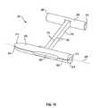
- FIG. 10is a perspective view of a further fastener embodying the invention.
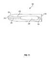
- FIG. 11is a side view of the fastener of FIG. 10 ;
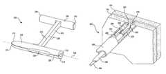
- FIG. 12is a perspective view with portions cut away of a fastener assembly according to another embodiment of the invention with the fastener prepositioned and in an early stage of being deployed;
- FIG. 13is a perspective view of the assembly of FIG. 12 shown with the fastener being driven in the tissue layers to be fastened;
- FIG. 14is a perspective view of the assembly of FIG. 12 shown with the fastener in an intermediate stage of deployment;
- FIG. 15is a perspective view of the assembly of FIG. 12 shown with the fastener almost completely deployed;
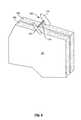
- FIG. 16is a perspective view showing the fastener of the assembly of FIG. 5 fully deployed
- FIG. 17is a perspective view of a fastener assembly according to an embodiment of the invention.
- FIG. 18is a perspective view, with portions cut away, of the assembly of FIG. 18 showing a fastener being driven into a fastener configuration structure according to an embodiment of the invention
- FIG. 19is a simplified side view, partly in section, of the fastener configuration structure of FIG. 19 ;
- FIG. 20is a perspective view of the assembly of FIGS. 18 and 19 along with a fastener loader according to an embodiment of the invention for loading fasteners into the deployment assembly.
- FIG. 1is a front cross-sectional view of the esophageal-gastro-intestinal tract 40 from a lower portion of the esophagus 41 to the duodenum 42 .
- the stomach 43is characterized by the greater curvature 44 on the anatomical left side and the lesser curvature 45 on the anatomical right side.
- the tissue of the outer surfaces of those curvaturesis referred to in the art as serosa tissue. As will be seen subsequently, the nature of the serosa tissue is used to advantage for its ability to bond to like serosa tissue.
- the Fundus 46 of the greater curvature 44forms the superior portion of the stomach 43 , and traps gas and air bubbles for burping.
- the esophageal tract 41enters the stomach 43 at an esophageal orifice below the superior portion of the fundus 46 , forming a cardiac notch 47 and an acute angle with respect to the Fundus 46 known as the Angle of His 57 .
- the lower esophageal sphincter (LES) 48is a discriminating sphincter able to distinguish between burping gas, liquids, and solids, and works in conjunction with the Fundus 46 to burp.
- the gastroesophageal flap valve (GEFV) 49includes a moveable portion and an opposing more stationary portion.
- the moveable portion of the GEFV 49is an approximately 180 degree, semicircular, gastroesophageal flap 50 (alternatively referred to as a “normal moveable flap” or “moveable flap”) formed of tissue at the intersection between the esophagus 41 and the stomach 43 .
- the opposing more stationary portion of the GEFV 49comprises a portion of the lesser curvature 45 of the stomach 43 adjacent to its junction with the esophagus 41 .
- the gastroesophageal flap 50 of the GEFV 49principally comprises tissue adjacent to the fundus 46 portion of the stomach 43 , is about 4 to 5 cm long ( 51 ) at it longest portion, and the length may taper at its anterior and posterior ends.
- the gastroesophageal flap 50is partially held against the lesser curvature 45 portion of the stomach 43 by the pressure differential between the stomach 43 and the thorax, and partially by the resiliency and the anatomical structure of the GEFV 49 , thus providing the valving function.
- the GEFV 49is similar to a flutter valve, with the gastroesophageal flap 50 being flexible and closeable against the other more stationary side.
- the esophageal tractis controlled by an upper esophageal sphincter (UES) in the neck near the mouth for swallowing, and by the LES 48 and the GEFV 49 at the stomach.
- the normal anti-reflux barrieris primarily formed by the LES 48 and the GEFV 49 acting in concert to allow food and liquid to enter the stomach, and to considerably resist reflux of stomach contents into the esophagus 41 past the gastroesophageal tissue junction 52 .
- Tissue aboral of the gastroesophageal tissue junction 52is generally considered part of the stomach because the tissue protected from stomach acid by its own protective mechanisms.
- Tissue oral of the gastroesophageal junction 52is generally considered part of the esophagus and it is not protected from injury by prolonged exposure to stomach acid.
- the juncture of the stomach and esophageal tissuesform a zigzag line, which is sometimes referred to as the “Z-line.”
- “stomach”means the tissue aboral of the gastroesophageal junction 52 .
- FIG. 2is a front cross-sectional view of an esophageal-gastro-intestinal tract illustrating a Grade I normal appearance movable flap 50 of the GEFV 49 (shown in dashed lines) and a deteriorated Grade III gastroesophageal flap 55 of the GEFV 49 (shown in solid lines).
- a principal reason for regurgitation associated with GERDis the mechanical failure of the deteriorated (or reflux appearance) gastroesophageal flap 55 of the GEFV 49 to close and seal against the higher pressure in the stomach. Due to reasons including lifestyle, a Grade I normal gastroesophageal flap 50 of the GEFV 49 may deteriorate into a Grade III deteriorated gastroesophageal flap 55 .
- the anatomical results of the deteriorationinclude moving a portion of the esophagus 41 that includes the gastroesophageal junction 52 and LES 48 toward the mouth, straightening of the cardiac notch 47 , and increasing the Angle of His 57 .
- the deteriorated gastroesophageal flap 55illustrates a gastroesophageal flap valve 49 and cardiac notch 47 that have both significantly degraded.
- Dr. Hill and colleaguesdeveloped a grading system to describe the appearance of the GEFV and the likelihood that a patient will experience chronic acid reflux. L. D.
- the normal movable flap 50 of the GEFV 49illustrates a Grade I flap valve that is the least likely to experience reflux.
- the deteriorated gastroesophageal flap 55 of the GEFV 49illustrates a Grade III (almost Grade IV) flap valve.
- a Grade IV flap valveis the most likely to experience reflux.
- Grades II and IIIreflect intermediate grades of deterioration and, as in the case of III, a high likelihood of experiencing reflux.
- the stomach contentsare presented a funnel-like opening directing the contents into the esophagus 41 and the greatest likelihood of experiencing reflux.
- a device for restoring the normal gastroesophageal flap valve anatomywhich device is one embodiment of the present invention.
- the fastener 100generally includes a first member 102 , a second member 104 , and a connecting member 106 .
- the first member 102 and second member 104are substantially parallel and substantially perpendicular to the connecting member 106 which connects the first member 102 to the second member 104 .
- the first and second members 102 and 104are generally cylindrical. Each has a longitudinal axis 108 and 110 and a through channel 112 and 114 along the longitudinal axes 108 and 110 .
- the through channels 112 and 114are formed by through bores which are dimensioned to be slidingly received on a tissue piercing deployment wire to be described hereinafter.
- the first member 102also includes a first end 116 and a second end 118 .
- the second member 114includes a first end 120 and a second end 122 .
- the first ends 116 and 120form pointed dilation tips 124 and 126 , respectively.
- the dilation tips 124 and 126are conical and more particularly take the shape of truncated cones.
- the pointed tips 129 and 126are pointed in opposite directions.
- the first and second members 102 and 104 and the connecting 106may be formed of different materials and have different textures. These materials may include, for example, plastic materials such as polypropylene, polyethylene, polyglycolic acid, polyurethane, or a thermoplastic elastomer.
- the connecting member 106has a vertical dimension 128 and a horizontal dimension 130 which is transverse to the vertical dimension. The horizontal dimension is substantially less than the vertical dimension to render the connecting member 106 readily bendable in a horizontal plane.
- the connecting memberis further rendered bendable by the nature of the plastic material from which the fastener 100 is formed.
- the connecting membermay be formed from either an elastic plastic or a permanently deformable plastic. An elastic material would prevent compression necrosis in some applications.
- the fastener 140includes a first member 142 , a second member 144 , and a connecting member 146 .
- the fastener 140may be formed in one piece and a plastic material similar to the fastener 100 of FIG. 3 .
- the fasteners 100 and 140may be formed of a plastic material which includes a color pigment, for example pthalocyanine blue, for contrasting with the color of body tissue to enable visualization of the fastener with an endoscope during the deployment of the fasteners.
- a color pigmentfor example pthalocyanine blue
- the fastener 140is impregnated with radio opaque material 148 so as to render the fastener 140 at least partially viewable under fluoroscopy.
- the radio opaque particlesmay be, for example, barium sulfate, bismuth subcarbonate, tungsten powder or tantalum powder.
- the second member 144 of the fastener 140includes a plurality of longitudinally spaced vertical slots 150 . This renders the second member 144 flexible in a direction opposite the slots but stiff in a direction of the slots. Hence, the second member 144 is resistant to bending in a first direction indicated by arrow 152 while being substantially less resistant to bending in a direction indicated by arrow 154 .
- the reduced resistance to bending in the direction 154 of the second member 144 of the fastener 140may be utilized to advantage in the deployment of the fastener 140 .
- FIG. 5it is a perspective view with portions cut away of a fastener assembly embodying the present invention.
- the tissue layer portions above the fastener 162have been shown cut away in FIGS. 5-9 to enable the deployment procedure to be seen more clearly.
- the assembly 160generally includes a fastener 162 , a deployment wire 164 , a pusher 166 , and a guide tube 168 .
- the fastener 162takes the form of a further fastener embodiment of the present invention and includes a first member 172 , a second member 174 , and a connecting member 176 .
- the fastener 162differs from the fasteners 100 and 140 of FIGS. 3 and 4 , respectively, in that the second member 174 is of solid construction and does not include a longitudinal through channel or a pointed tip.
- the first member 172includes a through channel as previously described and a pointed tip 175 .
- the first member 172 of the fastener 162is slidingly received on the deployment wire 164 .
- the deployment wire 164has a pointed tip 178 for piercing the tissue layers 180 and 182 to be fastened together.
- the tissue layers 180 and 182may be folded stomach tissue which are to be fastened and maintained together to form and maintain a gastroesophageal flap valve.
- the guide tube 168may take the form of a lumen within most any lumen providing structure such as a catheter, for example.
- the second member 174is disposed along side the first member 172 .
- the first member, connecting member, and second memberare arranged so that the connecting member 176 lies between the first member 172 and the second member 174 and, as illustrated, with the second member 174 trailing the first member 172 with respect to the tissue layers 180 and 182 .
- the tip 178 of the tissue piercing wire 164pierces the tissue layers 180 and 182 .
- the subassembly of the tissue piercing wire 164 , fastener 162 , and pusher 166may be guided to its intended location relative to the tissue layers 180 and 182 by the guide tube 168 .
- the pusher 166may be utilized to push the first member 172 of the fastener 162 through the tissue layers 180 and 182 on the tissue piercing wire 164 . This is illustrated in FIG. 6 . As the pusher 166 pushes the first member 172 through the tissue layers 180 and 182 , the connecting member 176 follows along beside and immediately adjacent to the first member 172 of the fastener 162 and the pusher 166 . As may be seen in FIG.
- the pusher 166continues to push the first member 172 of the fastener 162 through the tissue layers 180 and 182 on the tissue piercing wire 164 until the end 173 of the first member 172 engaging the pusher 166 clears the second tissue layer 182 . It may also be noted that at this time, the second member 174 of the fastener 162 has engaged the surface 181 of tissue layer 180 .
- the tissue piercing wire 164is then retracted within the pusher 166 to release the first member 172 .
- the first member 172being thus released from the tissue piercing wire 164 will return to its original configuration substantially parallel to the second member 174 and substantially perpendicular to the connecting member 176 .
- the tissue piercing wire 164 and pusher 166may be withdrawn.
- FIG. 9illustrates the fastener 162 in its deployed position. It will be noted that the tissue layers 180 and 182 are fastened together between the first member 172 of the fastener 162 and the second member 174 of the fastener 162 .
- the connecting member 176extends through the tissue layers 180 and 182 .
- FIG. 10is a perspective view and FIG. 11 is a side view of another fastener 200 embodying the present invention.
- the fastener 200generally includes a first member 202 , a second member 204 , and a connecting member 206 .
- the first member 202 and second member 204are substantially parallel to each other and substantially perpendicular to the connecting member 206 which connects the first member 202 to the second member 204 .
- the first member 202is generally cylindrical or can have any other shape. It has a longitudinal axis 208 and a through channel 212 along the longitudinal axis 208 .
- the through channel 212is formed by a through bore which is dimensioned to be slidingly received on a tissue piercing deployment wire to be described.
- the first member 202also includes a first end 216 and a second end 218 .
- the second member 204includes a first end 220 and a second end 222 .
- the first end 216 of member 202forms a pointed dilation tip 224 .
- the dilation tip 224may be conical and more particularly takes the shape of a truncated cone.
- the tipcan also be shaped to have a cutting edge in order to reduce tissue resistance.
- the first and second members 202 and 204 and the connecting member 206may be formed of different materials and have different textures. These materials may include, for example, plastic materials such as polypropylene, polyethylene, polyglycolic acid, polyurethane, or a thermoplastic elastomer. The plastic materials may include a pigment contrasting with body tissue color to enable better visualization of the fastener during its deployment. Alternatively, the fastener may be formed of a metal, such as stainless steel or a shape memory metal, such as Nitinol.
- the connecting member 206has a vertical dimension 228 and a horizontal dimension 230 which is transverse to the vertical dimension.
- the horizontal dimensionis substantially less than the vertical dimension to render the connecting member 206 readily bendable in a horizontal plane.
- the connecting memberis further rendered bendable by the nature of the material from which the fastener 200 is formed.
- the connecting membermay be formed from either an elastic plastic or a permanently deformable plastic. An elastic material would prevent compression necrosis in some applications.
- the first member 202has a continuous lengthwise slit 225 extending between the first and second ends 216 and 218 .
- the slit 225includes an optional slot portion 226 that communications with the through channel 212 .
- the slot 226has a transverse dimension for more readily enabling receipt of a tissue piercing deployment wire during deployment of the fastener 200 .
- the fastener number 202is formed of flexible material, the slit 225 may be made larger through separation to allow the deployment wire to be snapped into and released from the through channel 212 as will be seen subsequently. This permits release of the first member 202 during deployment.
- the slit 225extends substantially parallel to the through channel 212 and the center axis 208 of the first member 202 . It may also be noted that the slit 225 has a width dimension that is smaller or less than the diameter of the through channel 212 . This assures that the fastener 200 will remain on a tissue piercing deployment wire as it is pushed towards and into the tissue as will be seen subsequently.
- FIG. 12it is a perspective view with portions cut away of a fastener assembly 300 embodying the present invention for deploying the fastener 200 .
- the tissue layer portions above the fastener 200have been shown cut away in FIGS. 12-16 to enable the deployment procedure to be seen more clearly.
- the assembly 300generally includes the fastener 200 , a deployment wire 264 , a pusher 266 , and a guide tube 268 .
- the first member 202 of the fastener 200is slidingly received on the deployment wire 264 .
- the deployment wire 264has a pointed tip 278 for piercing the tissue layers 180 and 182 to be fastened together and to cut sufficient tissue to enable the fastener member 202 to readily pass through the tissue layers 180 and 182 . It may also serve as a guide to guide the wire 264 off of the member 202 at the end of the deployment.
- the tissue piercing wire 264 , fastener 200 , and the pusher 266are all within the guide tube 268 .
- the guide tube 268may take the form of a catheter, for example, as previously mentioned, or a guide channel within a block of material.
- the second member 204is disposed along side the first member 202 , with the connecting member between the first member 202 and the second member 204 .
- the second member 204also trails the first member 202 with respect to the tissue layers 180 and 182 . This is all rendered possible due to the flexibility of the connecting member 206 .
- the tip 278 of the tissue piercing wire 264pierces the tissue layers 180 and 182 .
- the subassembly of the tissue piercing wire 264 , fastener 200 , and pusher 266may be guided to its intended location relative to the tissue layers 280 and 282 by the guide tube 268 .
- the tissue piercing wire 264has pierced the tissue layers 180 and 182 and the pusher 266 has pushed the first member 202 of the fastener 200 through the tissue layers 180 and 182 on the tissue piercing wire 264 . This may be accomplished by moving the wire 264 and the pusher 266 together.
- wire 264has been pushed further forward and independently from the first member 202 and the pusher 266 .
- the first member 202has also been pushed forward by the pusher 266 to cause the second member 204 to engage the tissue layer 180 .
- Continued pushing of the first member 202causes the first member to pivot in a counter clockwise direction because the second member 204 is held by the tissue layer 180 .
- the counter clockwise movement of the first member 202causes the wire 264 to spread the slit 225 open, to pass down the slit to enter slot portion 226 and to eventually pass through the slit 225 at end 218 .
- the fastener 200is then released from the wire 264 .
- FIG. 15it will now be seen that the second end 218 of the first member 202 has cleared the wire 264 and tissue layer 182 .
- the tissue piercing wire 264may now be retracted into the pusher 266 and the tissue piercing wire 264 and pusher 266 may be withdrawn.
- FIG. 16illustrates the fastener 200 in its fully deployed position. It will be noted that the fastener has returned to its original shape.
- the tissue layers 180 and 182are fastened together between the first member 202 of the fastener 200 and the second member 204 of the fastener 200 .
- the connecting member 106extends through the tissue layers 180 and 182 .
- FIGS. 17 and 18illustrate a control assembly 400 for controlling the delivery and deployment of fasteners according to an embodiment of the present invention. More specifically, the assembly 400 , according to this embodiment, is adapted to be located at the proximal end of an assembly, such as those shown in FIGS. 5-9 and 12 - 16 for deploying fasteners into stomach tissue for maintaining manipulated stomach tissue which has been folded and molded to restore a GEFV flap.
- the assembly 400generally includes a housing 402 .
- the housingincludes identical, side-by-side control assemblies 404 and 406 . Since the control assemblies 404 and 406 are identical, only assembly 404 will be described in detail herein.
- the assembly 404includes a bolt 410 , a receiver 412 that slidingly receives the bolt 410 and the pusher 266 .
- Projecting from the boltis a handle 414 .
- the handleextends through a track 416 in the housing 402 and restricts and measures the movement of the bolt 410 .
- control assemblies 404 and 406are side-bi-side and identical.
- the assembly 406may also be seen to include a bolt 510 , a pusher 366 , a receiver 512 , and a handle 514 projecting through a track 516 .
- the operation of the assembly 406is identical to the operation of the assembly 404 to be described subsequently.
- the assembly 404still further includes a fastener loading station 420 .
- the loading station 420has a length dimension 422 sufficient to receive a fastener loader to be described subsequently with respect to FIG. 20 .
- the fastener loader and loading stationfacilitate loading of fasteners onto the deployment stylet 264 .
- the assembly 406also includes such a loading station 520 .
- the bolt 410 of assembly 404is attached to the proximal end of the stylet 264 .
- the bolt and styletare arranged for linear movement when the bolt 410 is moved within the receiver 412 with the handle 414 along the track 416 .
- the pusher 264intersects the path of the stylet 264 at an intersection point 418 .
- the pusheras best described in copending application Ser. No. 11/043,903, includes an opening at the intersection 418 .
- the openingpermits the stylet to be fed into the pusher and hence to allow the pusher 266 to be carried by the stylet 264 distal to the intersection 418 . As previously seen, this permits the pusher 266 to engage the fastener 200 .
- the loading station 420is distal to the intersection 418 to permit the fastener 200 to be loaded onto the stylet 264 and engaged by the pusher 266 .
- the bolt 410further includes a lumen 411 that slidingly receives the pusher 266 . This permits the movement of the pusher 266 to be controlled independently of the movement of the bolt 410 and the stylet 264 .
- the bolt 510also includes such a lumen 511 as may be seen in FIG. 17 .
- the assembly 404further includes a fastener configuration structure 428 including a funnel shaped wall 430 between the loading station 420 and the guide lumen 269 .
- the guide lumen 269guides the stylet 264 , fastener 200 , and pusher 266 to the desired location for deploying the fasteners.
- the funnel shaped wall 430serves to preposition the second member 204 of the fastener 200 within the guide lumen 269 as best seen in FIG. 12 .
- the second member 204is prepositioned as a trailing member along side the first member 202 with the connecting member 206 therebetween.
- This fastener configuration and prepositioningassists in the proper functioning of the second member 204 as the fastener 200 is deployed.
- the second member 204is automatically rendered in its preposition along side the first member 202 with the connecting member 206 therebetween as the fastener 200 is translated distally through the funnel shaped wall section towards the guide lumen 269 .
- FIG. 19illustrates this in greater detail.
- a fastener 200As it is pushed through the fastener configuration structure 432 .
- the second member 204 of the fastener 200engages the funnel shaped wall 430 .
- the funnel shaped wall 430guides the second member 204 .
- the connecting member 206is folded back to be between the first member 202 and the second member 206 of the fastener 200 .
- the fastener 200reaches the fastener configuration outlet 431 communicating with the guide lumen 269 , the second member 204 is automatically disposed trailing and along side the first member 202 with the connecting member 206 therebetween.
- the fasteneris now configured for dependable deployment.
- the handle 414 of assembly 400When it is time to advance the stylet 264 in through the tissue as shown in FIG. 15 , for example, the handle 414 of assembly 400 is moved in a distal direction forcing the stylet 264 to move distally. The handle and thus the stylet movement is restricted and measured by a transverse portion of slot 417 of the track 416 . The handle 414 may be locked in a longitudinal position within the transverse portion 417 of the track.
- the fastener 200is advanced by the pusher 266 . After a fastener is deployed, the distal end of the pusher is drawn back to be proximal to the loading station 420 to permit another fastener to be loaded onto the stylet 264 .
- the fastenersare loaded onto the stylet by presenting the slit 225 of the fasteners to the stylet.
- the slit 225( FIG. 11 ) is widened by the stylet 264 and the stylet 264 slips through the slit 225 and into the through channel 212 of the fastener first member 202 .
- FIG. 20shows a fastener loader 450 which may be employed for loading the fasteners onto the stylet.
- the loader 450has a handle 452 permitting it to be readily hand-holdable.
- the loaderis arranged to carry a plurality of fasteners 200 .
- the loaderpresents the fasteners so that the slit 225 will be aligned with the stylet 264 .
- the holderhas a width dimension 454 that is less than the length dimension 422 ( FIGS. 17 and 18 ) of the loading station 420 .
- the loader 450may be inserted into a loading station for mounting a fastener onto a corresponding stylet.
- the loader 450may be used on either side of the assembly 400 for loading a fastener onto stylet 264 at loading station 420 or loading a fastener onto stylet 364 at loading station 520 .
Landscapes
- Health & Medical Sciences (AREA)
- Surgery (AREA)
- Life Sciences & Earth Sciences (AREA)
- Medical Informatics (AREA)
- Nuclear Medicine, Radiotherapy & Molecular Imaging (AREA)
- Engineering & Computer Science (AREA)
- Biomedical Technology (AREA)
- Heart & Thoracic Surgery (AREA)
- Molecular Biology (AREA)
- Animal Behavior & Ethology (AREA)
- General Health & Medical Sciences (AREA)
- Public Health (AREA)
- Veterinary Medicine (AREA)
- Physiology (AREA)
- Rheumatology (AREA)
- Surgical Instruments (AREA)
Abstract
Description
Claims (4)
Priority Applications (2)
| Application Number | Priority Date | Filing Date | Title |
|---|---|---|---|
| US12/460,247US8337523B2 (en) | 2004-02-20 | 2009-07-15 | Tissue fixation assembly having prepositioned fasteners and method |
| US13/678,474US8961540B2 (en) | 2004-02-20 | 2012-11-15 | Tissue fixation assembly having prepositioned fasteners and method |
Applications Claiming Priority (3)
| Application Number | Priority Date | Filing Date | Title |
|---|---|---|---|
| US10/783,717US20050187565A1 (en) | 2004-02-20 | 2004-02-20 | Tissue fixation devices and a transoral endoscopic gastroesophageal flap valve restoration device and assembly using same |
| US11/172,363US20060009792A1 (en) | 2004-02-20 | 2005-06-29 | Tissue fixation assembly having prepositioned fasteners and method |
| US12/460,247US8337523B2 (en) | 2004-02-20 | 2009-07-15 | Tissue fixation assembly having prepositioned fasteners and method |
Related Parent Applications (1)
| Application Number | Title | Priority Date | Filing Date |
|---|---|---|---|
| US11/172,363ContinuationUS20060009792A1 (en) | 2004-02-20 | 2005-06-29 | Tissue fixation assembly having prepositioned fasteners and method |
Related Child Applications (1)
| Application Number | Title | Priority Date | Filing Date |
|---|---|---|---|
| US13/678,474ContinuationUS8961540B2 (en) | 2004-02-20 | 2012-11-15 | Tissue fixation assembly having prepositioned fasteners and method |
Publications (2)
| Publication Number | Publication Date |
|---|---|
| US20100023028A1 US20100023028A1 (en) | 2010-01-28 |
| US8337523B2true US8337523B2 (en) | 2012-12-25 |
Family
ID=37596039
Family Applications (2)
| Application Number | Title | Priority Date | Filing Date |
|---|---|---|---|
| US11/172,363AbandonedUS20060009792A1 (en) | 2004-02-20 | 2005-06-29 | Tissue fixation assembly having prepositioned fasteners and method |
| US12/460,247Expired - LifetimeUS8337523B2 (en) | 2004-02-20 | 2009-07-15 | Tissue fixation assembly having prepositioned fasteners and method |
Family Applications Before (1)
| Application Number | Title | Priority Date | Filing Date |
|---|---|---|---|
| US11/172,363AbandonedUS20060009792A1 (en) | 2004-02-20 | 2005-06-29 | Tissue fixation assembly having prepositioned fasteners and method |
Country Status (4)
| Country | Link |
|---|---|
| US (2) | US20060009792A1 (en) |
| EP (1) | EP1898805B1 (en) |
| ES (1) | ES2508890T3 (en) |
| WO (1) | WO2007002817A2 (en) |
Cited By (3)
| Publication number | Priority date | Publication date | Assignee | Title |
|---|---|---|---|---|
| EP2774547A1 (en) | 2013-03-08 | 2014-09-10 | EndoGastric Solutions, Inc. | Device for manipulating and fastening tissue |
| US10492782B2 (en) | 2002-06-25 | 2019-12-03 | Incisive Surgical, Inc. | Mechanical method and apparatus for bilateral tissue fastening |
| US11045195B2 (en) | 2014-04-25 | 2021-06-29 | Incisive Surgical, Inc. | Method and apparatus for wound closure with sequential tissue positioning and retention |
Families Citing this family (126)
| Publication number | Priority date | Publication date | Assignee | Title |
|---|---|---|---|---|
| JP2005522259A (en)* | 2002-04-10 | 2005-07-28 | タイコ ヘルスケア グループ エルピー | Surgical clip applier with high torque jaws |
| US20040193213A1 (en)* | 2003-03-11 | 2004-09-30 | Ernest Aranyi | Clip applying apparatus with curved jaws, and clip |
| EP1608272B1 (en)* | 2003-03-11 | 2017-01-25 | Covidien LP | Clip applying apparatus with angled jaw |
| US20050187565A1 (en) | 2004-02-20 | 2005-08-25 | Baker Steve G. | Tissue fixation devices and a transoral endoscopic gastroesophageal flap valve restoration device and assembly using same |
| US7632287B2 (en) | 2004-02-20 | 2009-12-15 | Endogastric Solutions, Inc. | Tissue fixation devices and assemblies for deploying the same |
| WO2006034403A2 (en) | 2004-09-23 | 2006-03-30 | Tyco Healthcare Group, Lp | Clip applying apparatus and ligation clip |
| EP2641548B1 (en)* | 2004-10-08 | 2015-08-19 | Covidien LP | Endoscopic surgical clip applier |
| US7819886B2 (en) | 2004-10-08 | 2010-10-26 | Tyco Healthcare Group Lp | Endoscopic surgical clip applier |
| US9763668B2 (en) | 2004-10-08 | 2017-09-19 | Covidien Lp | Endoscopic surgical clip applier |
| US8409222B2 (en)* | 2004-10-08 | 2013-04-02 | Covidien Lp | Endoscopic surgical clip applier |
| CA2809110A1 (en) | 2004-10-08 | 2006-04-20 | Tyco Healthcare Group Lp | Apparatus for applying surgical clips |
| US20060116697A1 (en) | 2004-11-30 | 2006-06-01 | Esophyx, Inc. | Flexible transoral endoscopic gastroesophageal flap valve restoration device and method |
| US20060167481A1 (en) | 2005-01-25 | 2006-07-27 | Esophyx, Inc. | Slitted tissue fixation devices and assemblies for deploying the same |
| US20070005082A1 (en) | 2005-06-29 | 2007-01-04 | Esophyx, Inc. | Apparatus and method for manipulating stomach tissue and treating gastroesophageal reflux disease |
| US20070038232A1 (en) | 2005-08-12 | 2007-02-15 | Kraemer Stefan J M | Apparatus and method for securing the stomach to the diaphragm for use, for example, in treating hiatal hernias and gastroesophageal reflux disease |
| US20070088373A1 (en) | 2005-10-18 | 2007-04-19 | Endogastric Solutions, Inc. | Invaginator for gastroesophageal flap valve restoration device |
| US20070089433A1 (en)* | 2005-10-20 | 2007-04-26 | Smurfit-Stone Container Enterprises, Inc. | Methods and systems for monitoring a shelf life of a product stored within a container |
| US9161754B2 (en) | 2012-12-14 | 2015-10-20 | Endogastric Solutions, Inc. | Apparatus and method for concurrently forming a gastroesophageal valve and tightening the lower esophageal sphincter |
| US20070129738A1 (en) | 2005-12-01 | 2007-06-07 | Endogastric Solutions, Inc. | Apparatus and method for concurrently forming a gastroesophageal valve and tightening the lower esophageal sphincter |
| USD629101S1 (en) | 2006-03-24 | 2010-12-14 | Tyco Healthcare Group Lp | Surgical clip applier |
| USD625009S1 (en) | 2006-03-24 | 2010-10-05 | Tyco Healthcare Group Lp | Surgical clip applier |
| US20070293879A1 (en)* | 2006-06-15 | 2007-12-20 | Endogastric Solutions, Inc. | Tissue fixation devices including reaction causing agents |
| CA2655197C (en)* | 2006-07-01 | 2014-02-18 | Opus Ksd Inc. | Tissue fasteners and related insertion devices, mechanisms, and methods |
| CA2605135C (en) | 2006-10-17 | 2014-12-30 | Tyco Healthcare Group Lp | Apparatus for applying surgical clips |
| WO2008085994A2 (en) | 2007-01-08 | 2008-07-17 | Endogastric Solutions | Connected fasteners, delivery device and method |
| EP2157920B1 (en) | 2007-03-26 | 2017-09-27 | Covidien LP | Endoscopic surgical clip applier |
| CN102327136B (en) | 2007-04-11 | 2014-04-23 | 柯惠Lp公司 | Surgical clip applier |
| US20110208212A1 (en) | 2010-02-19 | 2011-08-25 | Zergiebel Earl M | Surgical clip applier |
| US8056565B2 (en) | 2008-08-25 | 2011-11-15 | Tyco Healthcare Group Lp | Surgical clip applier and method of assembly |
| US8465502B2 (en) | 2008-08-25 | 2013-06-18 | Covidien Lp | Surgical clip applier and method of assembly |
| US8267944B2 (en) | 2008-08-29 | 2012-09-18 | Tyco Healthcare Group Lp | Endoscopic surgical clip applier with lock out |
| US9358015B2 (en)* | 2008-08-29 | 2016-06-07 | Covidien Lp | Endoscopic surgical clip applier with wedge plate |
| US8409223B2 (en) | 2008-08-29 | 2013-04-02 | Covidien Lp | Endoscopic surgical clip applier with clip retention |
| US8585717B2 (en)* | 2008-08-29 | 2013-11-19 | Covidien Lp | Single stroke endoscopic surgical clip applier |
| US8906037B2 (en) | 2009-03-18 | 2014-12-09 | Endogastric Solutions, Inc. | Methods and devices for forming a tissue fold |
| US8734469B2 (en) | 2009-10-13 | 2014-05-27 | Covidien Lp | Suture clip applier |
| US9186136B2 (en)* | 2009-12-09 | 2015-11-17 | Covidien Lp | Surgical clip applier |
| US8545486B2 (en) | 2009-12-15 | 2013-10-01 | Covidien Lp | Surgical clip applier |
| US8403945B2 (en) | 2010-02-25 | 2013-03-26 | Covidien Lp | Articulating endoscopic surgical clip applier |
| US8968337B2 (en) | 2010-07-28 | 2015-03-03 | Covidien Lp | Articulating clip applier |
| US8403946B2 (en) | 2010-07-28 | 2013-03-26 | Covidien Lp | Articulating clip applier cartridge |
| US9737289B2 (en)* | 2010-10-29 | 2017-08-22 | Vectec S.A. | Single use, disposable, tissue suspender device |
| US9011464B2 (en) | 2010-11-02 | 2015-04-21 | Covidien Lp | Self-centering clip and jaw |
| US9186153B2 (en) | 2011-01-31 | 2015-11-17 | Covidien Lp | Locking cam driver and jaw assembly for clip applier |
| US9775623B2 (en) | 2011-04-29 | 2017-10-03 | Covidien Lp | Surgical clip applier including clip relief feature |
| US20130066338A1 (en) | 2011-09-09 | 2013-03-14 | Richard Romley | Methods and devices for manipulating and fastening tissue |
| US9955957B2 (en) | 2011-09-09 | 2018-05-01 | Endogastric Solutions, Inc. | Methods and devices for manipulating and fastening tissue |
| US20130131697A1 (en) | 2011-11-21 | 2013-05-23 | Covidien Lp | Surgical clip applier |
| US9113868B2 (en) | 2011-12-15 | 2015-08-25 | Ethicon Endo-Surgery, Inc. | Devices and methods for endoluminal plication |
| US9173657B2 (en) | 2011-12-15 | 2015-11-03 | Ethicon Endo-Surgery, Inc. | Devices and methods for endoluminal plication |
| US9364239B2 (en) | 2011-12-19 | 2016-06-14 | Covidien Lp | Jaw closure mechanism for a surgical clip applier |
| US9364216B2 (en) | 2011-12-29 | 2016-06-14 | Covidien Lp | Surgical clip applier with integrated clip counter |
| US8992547B2 (en) | 2012-03-21 | 2015-03-31 | Ethicon Endo-Surgery, Inc. | Methods and devices for creating tissue plications |
| US9408610B2 (en) | 2012-05-04 | 2016-08-09 | Covidien Lp | Surgical clip applier with dissector |
| US9532787B2 (en) | 2012-05-31 | 2017-01-03 | Covidien Lp | Endoscopic clip applier |
| US9113892B2 (en) | 2013-01-08 | 2015-08-25 | Covidien Lp | Surgical clip applier |
| US9968362B2 (en) | 2013-01-08 | 2018-05-15 | Covidien Lp | Surgical clip applier |
| US9750500B2 (en) | 2013-01-18 | 2017-09-05 | Covidien Lp | Surgical clip applier |
| US9232943B2 (en) | 2013-01-31 | 2016-01-12 | Opus Ksd Inc. | Delivering bioabsorbable fasteners |
| US20150032130A1 (en) | 2013-07-24 | 2015-01-29 | Covidien Lp | Expanding absorbable tack |
| US9775624B2 (en) | 2013-08-27 | 2017-10-03 | Covidien Lp | Surgical clip applier |
| US10702278B2 (en) | 2014-12-02 | 2020-07-07 | Covidien Lp | Laparoscopic surgical ligation clip applier |
| US9931124B2 (en) | 2015-01-07 | 2018-04-03 | Covidien Lp | Reposable clip applier |
| CN107205747B (en) | 2015-01-15 | 2020-09-08 | 柯惠有限合伙公司 | Reusable endoscopic surgical clip applier |
| US10292712B2 (en) | 2015-01-28 | 2019-05-21 | Covidien Lp | Surgical clip applier with integrated cutter |
| US10159491B2 (en) | 2015-03-10 | 2018-12-25 | Covidien Lp | Endoscopic reposable surgical clip applier |
| CN108348259B (en) | 2015-11-03 | 2020-12-11 | 柯惠有限合伙公司 | Endoscopic Surgical Fixture Applicator |
| US10702280B2 (en) | 2015-11-10 | 2020-07-07 | Covidien Lp | Endoscopic reposable surgical clip applier |
| US10905425B2 (en) | 2015-11-10 | 2021-02-02 | Covidien Lp | Endoscopic reposable surgical clip applier |
| US10390831B2 (en) | 2015-11-10 | 2019-08-27 | Covidien Lp | Endoscopic reposable surgical clip applier |
| CN108472044B (en) | 2016-01-11 | 2021-04-16 | 柯惠有限合伙公司 | endoscope-reserved surgical clip applier |
| AU2016388454A1 (en) | 2016-01-18 | 2018-07-19 | Covidien Lp | Endoscopic surgical clip applier |
| CA2958160A1 (en) | 2016-02-24 | 2017-08-24 | Covidien Lp | Endoscopic reposable surgical clip applier |
| WO2018027788A1 (en) | 2016-08-11 | 2018-02-15 | Covidien Lp | Endoscopic surgical clip applier and clip applying systems |
| CN109640844B (en) | 2016-08-25 | 2021-08-06 | 柯惠Lp公司 | Endoscopic Surgical Clip Appliers and Applicator Systems |
| US10660651B2 (en) | 2016-10-31 | 2020-05-26 | Covidien Lp | Endoscopic reposable surgical clip applier |
| US10639044B2 (en) | 2016-10-31 | 2020-05-05 | Covidien Lp | Ligation clip module and clip applier |
| US10426489B2 (en) | 2016-11-01 | 2019-10-01 | Covidien Lp | Endoscopic reposable surgical clip applier |
| US10492795B2 (en) | 2016-11-01 | 2019-12-03 | Covidien Lp | Endoscopic surgical clip applier |
| US10610236B2 (en) | 2016-11-01 | 2020-04-07 | Covidien Lp | Endoscopic reposable surgical clip applier |
| US10709455B2 (en) | 2017-02-02 | 2020-07-14 | Covidien Lp | Endoscopic surgical clip applier |
| US10758244B2 (en) | 2017-02-06 | 2020-09-01 | Covidien Lp | Endoscopic surgical clip applier |
| US11116514B2 (en) | 2017-02-06 | 2021-09-14 | Covidien Lp | Surgical clip applier with user feedback feature |
| US10660725B2 (en) | 2017-02-14 | 2020-05-26 | Covidien Lp | Endoscopic surgical clip applier including counter assembly |
| US10603038B2 (en) | 2017-02-22 | 2020-03-31 | Covidien Lp | Surgical clip applier including inserts for jaw assembly |
| US11583291B2 (en) | 2017-02-23 | 2023-02-21 | Covidien Lp | Endoscopic surgical clip applier |
| US10548602B2 (en) | 2017-02-23 | 2020-02-04 | Covidien Lp | Endoscopic surgical clip applier |
| US10675043B2 (en) | 2017-05-04 | 2020-06-09 | Covidien Lp | Reposable multi-fire surgical clip applier |
| US10722235B2 (en) | 2017-05-11 | 2020-07-28 | Covidien Lp | Spring-release surgical clip |
| US10639032B2 (en) | 2017-06-30 | 2020-05-05 | Covidien Lp | Endoscopic surgical clip applier including counter assembly |
| US10660723B2 (en) | 2017-06-30 | 2020-05-26 | Covidien Lp | Endoscopic reposable surgical clip applier |
| US10675112B2 (en) | 2017-08-07 | 2020-06-09 | Covidien Lp | Endoscopic surgical clip applier including counter assembly |
| US10932790B2 (en) | 2017-08-08 | 2021-03-02 | Covidien Lp | Geared actuation mechanism and surgical clip applier including the same |
| US10863992B2 (en) | 2017-08-08 | 2020-12-15 | Covidien Lp | Endoscopic surgical clip applier |
| US10786262B2 (en) | 2017-08-09 | 2020-09-29 | Covidien Lp | Endoscopic reposable surgical clip applier |
| US10786263B2 (en) | 2017-08-15 | 2020-09-29 | Covidien Lp | Endoscopic reposable surgical clip applier |
| US10835341B2 (en) | 2017-09-12 | 2020-11-17 | Covidien Lp | Endoscopic surgical clip applier and handle assemblies for use therewith |
| US10835260B2 (en) | 2017-09-13 | 2020-11-17 | Covidien Lp | Endoscopic surgical clip applier and handle assemblies for use therewith |
| US10758245B2 (en) | 2017-09-13 | 2020-09-01 | Covidien Lp | Clip counting mechanism for surgical clip applier |
| US10653429B2 (en) | 2017-09-13 | 2020-05-19 | Covidien Lp | Endoscopic surgical clip applier |
| US11116513B2 (en) | 2017-11-03 | 2021-09-14 | Covidien Lp | Modular surgical clip cartridge |
| US10932791B2 (en) | 2017-11-03 | 2021-03-02 | Covidien Lp | Reposable multi-fire surgical clip applier |
| US10828036B2 (en) | 2017-11-03 | 2020-11-10 | Covidien Lp | Endoscopic surgical clip applier and handle assemblies for use therewith |
| US11376015B2 (en) | 2017-11-03 | 2022-07-05 | Covidien Lp | Endoscopic surgical clip applier and handle assemblies for use therewith |
| US10945734B2 (en) | 2017-11-03 | 2021-03-16 | Covidien Lp | Rotation knob assemblies and surgical instruments including the same |
| US10722236B2 (en) | 2017-12-12 | 2020-07-28 | Covidien Lp | Endoscopic reposable surgical clip applier |
| US10959737B2 (en) | 2017-12-13 | 2021-03-30 | Covidien Lp | Reposable multi-fire surgical clip applier |
| US10849630B2 (en) | 2017-12-13 | 2020-12-01 | Covidien Lp | Reposable multi-fire surgical clip applier |
| US10743887B2 (en) | 2017-12-13 | 2020-08-18 | Covidien Lp | Reposable multi-fire surgical clip applier |
| US11051827B2 (en) | 2018-01-16 | 2021-07-06 | Covidien Lp | Endoscopic surgical instrument and handle assemblies for use therewith |
| US10993721B2 (en) | 2018-04-25 | 2021-05-04 | Covidien Lp | Surgical clip applier |
| US10786273B2 (en) | 2018-07-13 | 2020-09-29 | Covidien Lp | Rotation knob assemblies for handle assemblies |
| US11259887B2 (en) | 2018-08-10 | 2022-03-01 | Covidien Lp | Feedback mechanisms for handle assemblies |
| US11278267B2 (en) | 2018-08-13 | 2022-03-22 | Covidien Lp | Latch assemblies and surgical instruments including the same |
| US11246601B2 (en) | 2018-08-13 | 2022-02-15 | Covidien Lp | Elongated assemblies for surgical clip appliers and surgical clip appliers incorporating the same |
| US11253267B2 (en) | 2018-08-13 | 2022-02-22 | Covidien Lp | Friction reduction mechanisms for handle assemblies |
| US11219463B2 (en) | 2018-08-13 | 2022-01-11 | Covidien Lp | Bilateral spring for surgical instruments and surgical instruments including the same |
| US11033256B2 (en) | 2018-08-13 | 2021-06-15 | Covidien Lp | Linkage assembly for reusable surgical handle assemblies |
| US11344316B2 (en) | 2018-08-13 | 2022-05-31 | Covidien Lp | Elongated assemblies for surgical clip appliers and surgical clip appliers incorporating the same |
| US11051828B2 (en) | 2018-08-13 | 2021-07-06 | Covidien Lp | Rotation knob assemblies and surgical instruments including same |
| US11147566B2 (en) | 2018-10-01 | 2021-10-19 | Covidien Lp | Endoscopic surgical clip applier |
| US11524398B2 (en) | 2019-03-19 | 2022-12-13 | Covidien Lp | Gear drive mechanisms for surgical instruments |
| US11779340B2 (en) | 2020-01-02 | 2023-10-10 | Covidien Lp | Ligation clip loading device |
| US11723669B2 (en) | 2020-01-08 | 2023-08-15 | Covidien Lp | Clip applier with clip cartridge interface |
| US12114866B2 (en) | 2020-03-26 | 2024-10-15 | Covidien Lp | Interoperative clip loading device |
| US12419648B2 (en) | 2022-09-26 | 2025-09-23 | Covidien Lp | Two-part fasteners for surgical clip appliers and surgical clip appliers for deploying the same |
Citations (2)
| Publication number | Priority date | Publication date | Assignee | Title |
|---|---|---|---|---|
| US4921479A (en)* | 1987-10-02 | 1990-05-01 | Joseph Grayzel | Catheter sheath with longitudinal seam |
| US20050043759A1 (en)* | 2003-07-14 | 2005-02-24 | Nmt Medical, Inc. | Tubular patent foramen ovale (PFO) closure device with catch system |
Family Cites Families (14)
| Publication number | Priority date | Publication date | Assignee | Title |
|---|---|---|---|---|
| US4696300A (en)* | 1985-04-11 | 1987-09-29 | Dennison Manufacturing Company | Fastener for joining materials |
| US5041129A (en)* | 1990-07-02 | 1991-08-20 | Acufex Microsurgical, Inc. | Slotted suture anchor and method of anchoring a suture |
| US5540718A (en)* | 1993-09-20 | 1996-07-30 | Bartlett; Edwin C. | Apparatus and method for anchoring sutures |
| US6071292A (en)* | 1997-06-28 | 2000-06-06 | Transvascular, Inc. | Transluminal methods and devices for closing, forming attachments to, and/or forming anastomotic junctions in, luminal anatomical structures |
| US6113609A (en)* | 1998-05-26 | 2000-09-05 | Scimed Life Systems, Inc. | Implantable tissue fastener and system for treating gastroesophageal reflux disease |
| US6113611A (en)* | 1998-05-28 | 2000-09-05 | Advanced Vascular Technologies, Llc | Surgical fastener and delivery system |
| CA2358387C (en)* | 1998-12-31 | 2007-11-13 | Jeffrey E. Yeung | Tissue fastening devices and delivery means |
| US7744613B2 (en)* | 1999-06-25 | 2010-06-29 | Usgi Medical, Inc. | Apparatus and methods for forming and securing gastrointestinal tissue folds |
| US6743239B1 (en)* | 2000-05-25 | 2004-06-01 | St. Jude Medical, Inc. | Devices with a bendable tip for medical procedures |
| FR2817142B1 (en)* | 2000-11-24 | 2003-05-16 | Sofradim Production | PROSTHETIC FASTENER AND TRANSCUTANEOUS INSERTION DEVICE |
| US20050085829A1 (en)* | 2002-05-17 | 2005-04-21 | Esophyx, Inc. | Transoral endoscopic gastroesophageal flap valve restoration device, assembly, system and method |
| US6790214B2 (en)* | 2002-05-17 | 2004-09-14 | Esophyx, Inc. | Transoral endoscopic gastroesophageal flap valve restoration device, assembly, system and method |
| EP1596723A2 (en)* | 2003-02-04 | 2005-11-23 | ev3 Sunnyvale, Inc. | Patent foramen ovale closure system |
| US7632287B2 (en)* | 2004-02-20 | 2009-12-15 | Endogastric Solutions, Inc. | Tissue fixation devices and assemblies for deploying the same |
- 2005
- 2005-06-29USUS11/172,363patent/US20060009792A1/ennot_activeAbandoned
- 2006
- 2006-06-28EPEP06785826.6Apatent/EP1898805B1/enactiveActive
- 2006-06-28WOPCT/US2006/025341patent/WO2007002817A2/enactiveApplication Filing
- 2006-06-28ESES06785826.6Tpatent/ES2508890T3/enactiveActive
- 2009
- 2009-07-15USUS12/460,247patent/US8337523B2/ennot_activeExpired - Lifetime
Patent Citations (2)
| Publication number | Priority date | Publication date | Assignee | Title |
|---|---|---|---|---|
| US4921479A (en)* | 1987-10-02 | 1990-05-01 | Joseph Grayzel | Catheter sheath with longitudinal seam |
| US20050043759A1 (en)* | 2003-07-14 | 2005-02-24 | Nmt Medical, Inc. | Tubular patent foramen ovale (PFO) closure device with catch system |
Cited By (6)
| Publication number | Priority date | Publication date | Assignee | Title |
|---|---|---|---|---|
| US10492782B2 (en) | 2002-06-25 | 2019-12-03 | Incisive Surgical, Inc. | Mechanical method and apparatus for bilateral tissue fastening |
| US11419607B2 (en) | 2002-06-25 | 2022-08-23 | Incisive Surgical, Inc. | Mechanical method and apparatus for bilateral tissue fastening |
| EP2774547A1 (en) | 2013-03-08 | 2014-09-10 | EndoGastric Solutions, Inc. | Device for manipulating and fastening tissue |
| EP3132753A1 (en) | 2013-03-08 | 2017-02-22 | EndoGastric Solutions, Inc. | Device for manipulating and fastening tissue |
| US11045195B2 (en) | 2014-04-25 | 2021-06-29 | Incisive Surgical, Inc. | Method and apparatus for wound closure with sequential tissue positioning and retention |
| US12042149B2 (en) | 2014-04-25 | 2024-07-23 | Incisive Surgical, Inc. | Method and apparatus for wound closure with sequential tissue positioning and retention |
Also Published As
| Publication number | Publication date |
|---|---|
| WO2007002817A3 (en) | 2007-04-05 |
| EP1898805B1 (en) | 2014-08-13 |
| US20100023028A1 (en) | 2010-01-28 |
| WO2007002817A2 (en) | 2007-01-04 |
| US20060009792A1 (en) | 2006-01-12 |
| EP1898805A4 (en) | 2013-02-27 |
| ES2508890T3 (en) | 2014-10-16 |
| EP1898805A2 (en) | 2008-03-19 |
Similar Documents
| Publication | Publication Date | Title |
|---|---|---|
| US8337523B2 (en) | Tissue fixation assembly having prepositioned fasteners and method | |
| US20210338230A1 (en) | Tissue fixation devices and a transoral endoscopic gastroesophageal flap valve restoration device and assembly using same | |
| US10357245B2 (en) | Tissue fixation devices and assemblies for deploying the same | |
| US11484305B2 (en) | Slitted tissue fixation devices and assemblies for deploying the same | |
| US20060253130A1 (en) | Tissue fixation assemblies having a plurality of fasteners ready for serial deployment | |
| US20070005080A1 (en) | Bolt action fastener delivery assembly | |
| US20060253131A1 (en) | Tissue fixation assemblies providing single stroke deployment | |
| US8961540B2 (en) | Tissue fixation assembly having prepositioned fasteners and method | |
| US11272926B2 (en) | Tissue fixation devices and assemblies for deploying the same |
Legal Events
| Date | Code | Title | Description |
|---|---|---|---|
| STCF | Information on status: patent grant | Free format text:PATENTED CASE | |
| AS | Assignment | Owner name:CRG SERVICING LLC, TEXAS Free format text:SECURITY INTEREST;ASSIGNOR:ENDOGASTRIC SOLUTIONS, INC.;REEL/FRAME:037172/0673 Effective date:20151125 | |
| FPAY | Fee payment | Year of fee payment:4 | |
| MAFP | Maintenance fee payment | Free format text:PAYMENT OF MAINTENANCE FEE, 8TH YR, SMALL ENTITY (ORIGINAL EVENT CODE: M2552); ENTITY STATUS OF PATENT OWNER: SMALL ENTITY Year of fee payment:8 | |
| MAFP | Maintenance fee payment | Free format text:PAYMENT OF MAINTENANCE FEE, 12TH YR, SMALL ENTITY (ORIGINAL EVENT CODE: M2553); ENTITY STATUS OF PATENT OWNER: SMALL ENTITY Year of fee payment:12 | |
| AS | Assignment | Owner name:ENDOGASTRIC SOLUTIONS, INC., WASHINGTON Free format text:ASSIGNMENT OF ASSIGNORS INTEREST;ASSIGNORS:BAKER, STEVE G.;CARTER, BRETT J.;KRAEMER, STEFAN J.M.;AND OTHERS;SIGNING DATES FROM 20051013 TO 20051026;REEL/FRAME:067835/0430 Owner name:OAKWOOD MEDICAL INVESTORS IV, L.L.C., MISSOURI Free format text:SECURITY AGREEMENT;ASSIGNOR:ENDOGASTRIC SOLUTIONS, INC.;REEL/FRAME:067839/0438 Effective date:20090409 Owner name:OAKWOOD MEDICAL INVESTORS IV (QP), L.L.C., MISSOURI Free format text:SECURITY AGREEMENT;ASSIGNOR:ENDOGASTRIC SOLUTIONS, INC.;REEL/FRAME:067839/0438 Effective date:20090409 Owner name:DE NOVO VENTURES III, LP, CALIFORNIA Free format text:SECURITY AGREEMENT;ASSIGNOR:ENDOGASTRIC SOLUTIONS, INC.;REEL/FRAME:067839/0438 Effective date:20090409 Owner name:MPM ASSET MANAGEMENT INVESTORS 2000 B LLC, MASSACHUSETTS Free format text:SECURITY AGREEMENT;ASSIGNOR:ENDOGASTRIC SOLUTIONS, INC.;REEL/FRAME:067839/0438 Effective date:20090409 Owner name:MPM BIOVENTURES GMBH & CO. PARALLEL-BETEILIGUNGS KG, MASSACHUSETTS Free format text:SECURITY AGREEMENT;ASSIGNOR:ENDOGASTRIC SOLUTIONS, INC.;REEL/FRAME:067839/0438 Effective date:20090409 Owner name:MPM BIOVENTURES II-QP, L.P., MASSACHUSETTS Free format text:SECURITY AGREEMENT;ASSIGNOR:ENDOGASTRIC SOLUTIONS, INC.;REEL/FRAME:067839/0438 Effective date:20090409 Owner name:MPM BIOVENTURES II, L.P., MASSACHUSETTS Free format text:SECURITY AGREEMENT;ASSIGNOR:ENDOGASTRIC SOLUTIONS, INC.;REEL/FRAME:067839/0438 Effective date:20090409 Owner name:MPM ASSET MANAGEMENT INVESTORS 2003 BVIII LLC, MASSACHUSETTS Free format text:SECURITY AGREEMENT;ASSIGNOR:ENDOGASTRIC SOLUTIONS, INC.;REEL/FRAME:067839/0438 Effective date:20090409 Owner name:MPM BIOVENTURES III PARALLEL FUND, L.P., MASSACHUSETTS Free format text:SECURITY AGREEMENT;ASSIGNOR:ENDOGASTRIC SOLUTIONS, INC.;REEL/FRAME:067839/0438 Effective date:20090409 Owner name:MPM BIOVENTURES III GMBH & CO. BETEILIGUNGS KG, MASSACHUSETTS Free format text:SECURITY AGREEMENT;ASSIGNOR:ENDOGASTRIC SOLUTIONS, INC.;REEL/FRAME:067839/0438 Effective date:20090409 Owner name:MPM BIOVENTURES III-QP, L.P., MASSACHUSETTS Free format text:SECURITY AGREEMENT;ASSIGNOR:ENDOGASTRIC SOLUTIONS, INC.;REEL/FRAME:067839/0438 Effective date:20090409 Owner name:MPM BIOVENTURES III, L.P., MASSACHUSETTS Free format text:SECURITY AGREEMENT;ASSIGNOR:ENDOGASTRIC SOLUTIONS, INC.;REEL/FRAME:067839/0438 Effective date:20090409 Owner name:ATV ENTREPRENEURS VII, L.P., MASSACHUSETTS Free format text:SECURITY AGREEMENT;ASSIGNOR:ENDOGASTRIC SOLUTIONS, INC.;REEL/FRAME:067839/0438 Effective date:20090409 Owner name:ADVANCED TECHNOLOGY VENTURES VII (C), L.P., MASSACHUSETTS Free format text:SECURITY AGREEMENT;ASSIGNOR:ENDOGASTRIC SOLUTIONS, INC.;REEL/FRAME:067839/0438 Effective date:20090409 Owner name:ADVANCED TECHNOLOGY VENTURES VII (B), L.P., MASSACHUSETTS Free format text:SECURITY AGREEMENT;ASSIGNOR:ENDOGASTRIC SOLUTIONS, INC.;REEL/FRAME:067839/0438 Effective date:20090409 Owner name:ADVANCED TECHNOLOGY VENTURES VII, L.P., MASSACHUSETTS Free format text:SECURITY AGREEMENT;ASSIGNOR:ENDOGASTRIC SOLUTIONS, INC.;REEL/FRAME:067839/0438 Effective date:20090409 Owner name:FOUNDATION MEDICAL PARTNERS II, L.P., CONNECTICUT Free format text:SECURITY AGREEMENT;ASSIGNOR:ENDOGASTRIC SOLUTIONS, INC.;REEL/FRAME:067839/0438 Effective date:20090409 Owner name:CHICAGO GROWTH PARTNERS, LP, ILLINOIS Free format text:SECURITY AGREEMENT;ASSIGNOR:ENDOGASTRIC SOLUTIONS, INC.;REEL/FRAME:067839/0438 Effective date:20090409 Owner name:ENDOGASTRIC SOLUTIONS, INC., WASHINGTON Free format text:RELEASE BY SECURED PARTY;ASSIGNORS:CHICAGO GROWTH PARTNERS, LP;DE NOVO VENTURES III, LP;MPM BIOVENTURES GMBH & CO. PARALLEL-BETEILIGUNGS KG;AND OTHERS;SIGNING DATES FROM 20100128 TO 20100210;REEL/FRAME:067839/0637 | |
| AS | Assignment | Owner name:ENDOGASTRIC SOLUTIONS, INC., WASHINGTON Free format text:RELEASE BY SECURED PARTY;ASSIGNOR:CRG SERVICING LLC;REEL/FRAME:068118/0166 Effective date:20240701 | |
| AS | Assignment | Owner name:ENDOGASTRIC SOLUTIONS, INC., WASHINGTON Free format text:RELEASE BY SECURED PARTY;ASSIGNOR:CRG SERVICING LLC;REEL/FRAME:068047/0253 Effective date:20240701 | |
| AS | Assignment | Owner name:MERIT MEDICAL SYSTEMS, INC., UTAH Free format text:ASSIGNMENT OF ASSIGNORS INTEREST;ASSIGNOR:ENDOGASTRIC SOLUTIONS, INC.;REEL/FRAME:068325/0865 Effective date:20240701 | |
| AS | Assignment | Owner name:WELLS FARGO BANK, NATIONAL ASSOCIATION, AS ADMINISTRATIVE AGENT, NORTH CAROLINA Free format text:SECURITY INTEREST;ASSIGNOR:MERIT MEDICAL SYSTEMS, INC.;REEL/FRAME:070060/0361 Effective date:20250128 |