US8337451B2 - Recirculation minimizing catheter - Google Patents
Recirculation minimizing catheterDownload PDFInfo
- Publication number
- US8337451B2 US8337451B2US12/254,532US25453208AUS8337451B2US 8337451 B2US8337451 B2US 8337451B2US 25453208 AUS25453208 AUS 25453208AUS 8337451 B2US8337451 B2US 8337451B2
- Authority
- US
- United States
- Prior art keywords
- partition
- tip
- opening
- orifice
- catheter
- Prior art date
- Legal status (The legal status is an assumption and is not a legal conclusion. Google has not performed a legal analysis and makes no representation as to the accuracy of the status listed.)
- Expired - Fee Related
Links
Images


Classifications
- A—HUMAN NECESSITIES
- A61—MEDICAL OR VETERINARY SCIENCE; HYGIENE
- A61M—DEVICES FOR INTRODUCING MEDIA INTO, OR ONTO, THE BODY; DEVICES FOR TRANSDUCING BODY MEDIA OR FOR TAKING MEDIA FROM THE BODY; DEVICES FOR PRODUCING OR ENDING SLEEP OR STUPOR
- A61M25/00—Catheters; Hollow probes
- A61M25/0021—Catheters; Hollow probes characterised by the form of the tubing
- A61M25/0023—Catheters; Hollow probes characterised by the form of the tubing by the form of the lumen, e.g. cross-section, variable diameter
- A61M25/0026—Multi-lumen catheters with stationary elements
- A61M25/0032—Multi-lumen catheters with stationary elements characterized by at least one unconventionally shaped lumen, e.g. polygons, ellipsoids, wedges or shapes comprising concave and convex parts
- A—HUMAN NECESSITIES
- A61—MEDICAL OR VETERINARY SCIENCE; HYGIENE
- A61M—DEVICES FOR INTRODUCING MEDIA INTO, OR ONTO, THE BODY; DEVICES FOR TRANSDUCING BODY MEDIA OR FOR TAKING MEDIA FROM THE BODY; DEVICES FOR PRODUCING OR ENDING SLEEP OR STUPOR
- A61M25/00—Catheters; Hollow probes
- A61M25/0067—Catheters; Hollow probes characterised by the distal end, e.g. tips
- A61M25/0068—Static characteristics of the catheter tip, e.g. shape, atraumatic tip, curved tip or tip structure
- A61M25/007—Side holes, e.g. their profiles or arrangements; Provisions to keep side holes unblocked
- A—HUMAN NECESSITIES
- A61—MEDICAL OR VETERINARY SCIENCE; HYGIENE
- A61M—DEVICES FOR INTRODUCING MEDIA INTO, OR ONTO, THE BODY; DEVICES FOR TRANSDUCING BODY MEDIA OR FOR TAKING MEDIA FROM THE BODY; DEVICES FOR PRODUCING OR ENDING SLEEP OR STUPOR
- A61M25/00—Catheters; Hollow probes
- A61M25/0021—Catheters; Hollow probes characterised by the form of the tubing
- A61M25/0023—Catheters; Hollow probes characterised by the form of the tubing by the form of the lumen, e.g. cross-section, variable diameter
- A61M25/0026—Multi-lumen catheters with stationary elements
- A61M25/003—Multi-lumen catheters with stationary elements characterized by features relating to least one lumen located at the distal part of the catheter, e.g. filters, plugs or valves
- A61M2025/0031—Multi-lumen catheters with stationary elements characterized by features relating to least one lumen located at the distal part of the catheter, e.g. filters, plugs or valves characterized by lumina for withdrawing or delivering, i.e. used for extracorporeal circuit treatment
- A—HUMAN NECESSITIES
- A61—MEDICAL OR VETERINARY SCIENCE; HYGIENE
- A61M—DEVICES FOR INTRODUCING MEDIA INTO, OR ONTO, THE BODY; DEVICES FOR TRANSDUCING BODY MEDIA OR FOR TAKING MEDIA FROM THE BODY; DEVICES FOR PRODUCING OR ENDING SLEEP OR STUPOR
- A61M25/00—Catheters; Hollow probes
- A61M25/0021—Catheters; Hollow probes characterised by the form of the tubing
- A61M25/0023—Catheters; Hollow probes characterised by the form of the tubing by the form of the lumen, e.g. cross-section, variable diameter
- A61M25/0026—Multi-lumen catheters with stationary elements
- A61M2025/0037—Multi-lumen catheters with stationary elements characterized by lumina being arranged side-by-side
- A—HUMAN NECESSITIES
- A61—MEDICAL OR VETERINARY SCIENCE; HYGIENE
- A61M—DEVICES FOR INTRODUCING MEDIA INTO, OR ONTO, THE BODY; DEVICES FOR TRANSDUCING BODY MEDIA OR FOR TAKING MEDIA FROM THE BODY; DEVICES FOR PRODUCING OR ENDING SLEEP OR STUPOR
- A61M25/00—Catheters; Hollow probes
- A61M25/0067—Catheters; Hollow probes characterised by the distal end, e.g. tips
- A61M25/0068—Static characteristics of the catheter tip, e.g. shape, atraumatic tip, curved tip or tip structure
- A61M2025/0073—Tip designed for influencing the flow or the flow velocity of the fluid, e.g. inserts for twisted or vortex flow
- A—HUMAN NECESSITIES
- A61—MEDICAL OR VETERINARY SCIENCE; HYGIENE
- A61M—DEVICES FOR INTRODUCING MEDIA INTO, OR ONTO, THE BODY; DEVICES FOR TRANSDUCING BODY MEDIA OR FOR TAKING MEDIA FROM THE BODY; DEVICES FOR PRODUCING OR ENDING SLEEP OR STUPOR
- A61M25/00—Catheters; Hollow probes
- A61M25/0021—Catheters; Hollow probes characterised by the form of the tubing
- A61M25/0023—Catheters; Hollow probes characterised by the form of the tubing by the form of the lumen, e.g. cross-section, variable diameter
- A61M25/0026—Multi-lumen catheters with stationary elements
- A61M25/003—Multi-lumen catheters with stationary elements characterized by features relating to least one lumen located at the distal part of the catheter, e.g. filters, plugs or valves
- Y—GENERAL TAGGING OF NEW TECHNOLOGICAL DEVELOPMENTS; GENERAL TAGGING OF CROSS-SECTIONAL TECHNOLOGIES SPANNING OVER SEVERAL SECTIONS OF THE IPC; TECHNICAL SUBJECTS COVERED BY FORMER USPC CROSS-REFERENCE ART COLLECTIONS [XRACs] AND DIGESTS
- Y10—TECHNICAL SUBJECTS COVERED BY FORMER USPC
- Y10T—TECHNICAL SUBJECTS COVERED BY FORMER US CLASSIFICATION
- Y10T29/00—Metal working
- Y10T29/49—Method of mechanical manufacture
- Y10T29/49826—Assembling or joining
Definitions
- the treatment of chronic diseaseoften involves the use of catheters to simultaneously inject and withdraw fluids from the vascular system.
- a large amount of bloodis withdrawn, treated externally and then returned to the vascular system.
- the removal and return of the bloodis generally carried out using a catheter and needle assembly with a first lumen aspiring blood from a vein while another returns the treated blood.
- Inlet and outlet orifices of the assemblyare generally spaced from one another to minimize recirculation of the returned blood into the inlet orifice.
- the present inventionis directed to a flow control tip for a catheter comprising a partition dividing the catheter into first and second lumens, a first orifice fluidly connected to the first lumen and a second orifice fluidly connected to the second lumen, the first orifice being proximal to the second orifice, an elongate protrusion extending along a portion of the partition substantially along a centerline of the elongated body and a deflecting surface extending at an angle relative to the protrusion to direct flow from the first orifice away from the centerline.
- FIG. 1is a perspective view of a conventional dual lumen catheter
- FIG. 2is a cross-section of the catheter of FIG. 1 taken along line A-A;
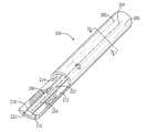
- FIG. 3is a perspective view of a catheter according to an embodiment of the present invention.
- FIG. 4is a cross-sectional view of the catheter of FIG. 3 taken along line IV-IV;
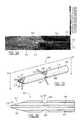
- FIG. 5is a side view of the catheter of FIG. 3 showing a computed flow pattern around a distal tip thereof;
- FIG. 6is a perspective view of a catheter according to an embodiment of the present invention.
- FIG. 7is a cross-sectional view of the catheter of FIG. 6 taken along line VII-VII;
- FIG. 8is a side view of the catheter of FIG. 6 showing a computed flow pattern around a distal tip thereof;
- FIG. 9is a perspective view of a catheter according to an embodiment of the present invention.
- FIG. 10is a cross-sectional view of the catheter of FIG. 9 taken along line X-X;
- FIG. 11is a side view of the catheter of FIG. 9 catheter of FIG. 2 showing a computed flow pattern around a distal tip thereof;
- FIG. 12is a perspective view of a catheter according to another embodiment of the present invention.
- FIG. 13is a cross-sectional view of the catheter of FIG. 12 taken along line
- FIG. 14is a side view of the catheter of FIG. 12 showing a computed flow pattern around a distal tip thereof;
- FIG. 15is a perspective view of a catheter according to an embodiment of the present invention.
- FIG. 16is a cross-sectional view of the catheter of FIG. 15 taken along line XVI-XVI;
- FIG. 17is a side view of the catheter of FIG. 15 showing a computed flow pattern around a distal tip thereof;
- FIG. 18is a perspective view of a catheter according to an embodiment of the present invention.
- FIG. 19is a side view of the catheter of FIG. 18 showing a computed flow pattern around a distal tip thereof.
- the present inventionmay be further understood with reference to the following description and the appended drawings, wherein like elements are referred to with the same reference numerals.
- the present inventionrelates to devices for accessing the vascular system and, in particular, to catheters for withdrawing and returning blood during dialysis. More particularly, the invention relates to catheter tips that minimize recirculation during such procedures.
- catheter tipsthat minimize recirculation during such procedures.
- the present inventionmay also be successfully implemented in other catheter components, such as, for example, catheter side ports.
- cathetersare generally designed for the standard flow mode (i.e., aspiration into a first orifice optimized as an inlet and outflow from a second orifice optimized as an outlet), the geometry of the distal tip is imperfectly adapted to reverse flow and recirculation tends to increase during reverse flow.
- Exemplary embodiments of the present inventionprovide a dual lumen catheter tip reducing recirculation in various modes of operation while reducing manufacturing costs. More specifically, tips for multi-lumen catheters according to the invention are manufactured using extrusion techniques such as, for example, skiving, drilling, heat-forming and RF tipping to obtain profiles that reduce recirculation in the normal and reverse modes of operation. As the exemplary tips may be formed without the need to join separate bodies (e.g., by bonding a molded tip to a separate structure) manufacturing costs are reduced.
- FIGS. 1 and 2show a conventional dual lumen catheter 100 (e.g., a Vaxcel® Plus dialysis catheter) comprising an elongate body defining first and second lumens 112 , 114 , respectively, separated by a partition 116 .
- a substantially cylindrical outer wall 110surrounds both lumens 112 , 114 and provides structural integrity to the catheter 100 .
- the distal tip 102 of the catheter 100comprises a first orifice 104 in fluid connection with the lumen 114 and, staggered from the first orifice 104 , a second orifice 106 in fluid connection with the lumen 112 .
- first lumen 112 and the first orifice 104function as inlets for the aspiration of blood while the second lumen 114 and the second orifice 106 function as outlets for blood returning from dialysis treatment.
- the roles of the orifices 104 , 106 and the lumens 112 , 114are reversed during the reverse mode of operation.
- a catheter tip 200comprises an elongated shell 202 including a first lumen 204 which, in the normal mode of operation, aspirates fluid from the vascular system (i.e., an inflow lumen) via a first orifice 214 and a second lumen 206 which, in the normal mode of operation, returns fluid from the catheter tip 200 to the vascular system (i.e., an outflow lumen) via a second orifice 216 .
- the lumens 204 and 206are separated by a partition 212 extending substantially the length of the tip 200 .
- the partition 212divides the tip 200 to form the lumens 204 and 206 as substantially equal in size and substantially semicircular.
- the shell 202extends around the tip 200 on one side of the partition 212 to the second orifice 216 and to the first orifice 214 on the other side of the partition 212 .
- the tip 200may be integrally formed as part of a catheter, or may be manufactured separately and then attached to a catheter via any of a variety of conventional attachment methods. It will also be understood that, if desired, the tip 200 may include more than two lumens.
- a protrusion 210which, in this embodiment is a substantially cylindrical extrusion with a diameter smaller than an inner diameter of the shell 202 forms a rod extending substantially along a centerline of the partition 212 , coaxially with the shell 202 .
- the protrusion 210extends along substantially the entire length of the shell 202 above the partition 212 in the distal portion 220 of the tip 200 , beyond the first orifice 214 .
- the protrusion 210is concentric with the shell 202 .
- the protrusion 210may not be concentric.
- the shape of the protrusion 210need not be circular and in other embodiments, the shape (e.g., triangular, elliptical, etc.) and/or the diameter of the protrusion 210 may be adjusted to suit a particular need (e.g., a desired flow characteristic, flexibility, etc.).
- the protrusion 210comprises a diverting structure 208 which, in this embodiment is formed as a shallow cut positioned approximately half the distance along the longitudinal axis of the tip 200 between the first orifice 214 and the second orifice 216 .
- the diverting structure 208may be formed anywhere between the first and second orifices 214 , 216 , respectively.
- the diverting structure 208may be sculpted by, for example, skiving a portion of the protrusion 210 to form a downward sloping diverting structure 222 and an upward sloping diverting structure 224 .
- the diverting structure 208may be formed by cutting the protrusion 210 along a substantially constant radius.
- the protrusion 210 and the diverting structure 208direct outflow from the outlet orifice 214 upward, away from the longitudinal axis of the tip 200 and the inlet orifice 216 .
- Additional embodimentsmay include multiple angled cuts formed by a series of skives, compound cuts, or any other method known to those skilled in the art.
- One or more of the multiple cutsmay be angled about a radial axis of the tip 200 to bias flow to side of the tip 200 or to bias portions of the flows in different directions relative to an axis of the tip 200 .
- the diverting structure 208may guide the flow laterally relative to the axis of the tip 200 in addition to diversion of the flow radially outward from the axis.
- the second orifice 216is formed at an angle, extending proximally at an acute or, in the alternative, an obtuse, angle from a distal end of the partition 212 which is preferably selected to provide desired flow characteristics to the tip 200 .
- a steeper anglemay direct fluid further from the centerline in the reverse mode and draw fluid from further away in the normal mode.
- this anglemay be formed by cutting the tip 200 along a desired plane, by molding, compound cutting, or by any other conventional method.
- FIG. 5A computational fluid dynamics analysis of the flow generated by the exemplary tip described above in the reverse mode of operation is shown in FIG. 5 .
- filtered blood 254flows out of the lumen 204 to exit the tip 200 via the first orifice 214 , initially passing over the protrusion 210 .
- the diverting structure 208it is pushed away from the centerline of the tip 200 and away from the second orifice 216 as indicated by the transition from section 256 (dark shade of gray) to section 258 (light shade of gray), reducing recirculation.
- the flowis biased to one side (e.g., into the plane of the side view of FIG. 5 ).
- unfiltered blood 250is aspired into the second orifice 216 , together with a reduced portion of the filtered blood 254 .
- the numerical modelingpredicts a recirculation rate of about 15% for the conditions shown in FIG. 5 .
- FIGS. 6 and 7show a catheter tip 300 according to an exemplary embodiment of the invention.
- the tip 300comprises an elongated shell 302 including a first lumen 304 which, in the normal mode of operation, aspirates fluid from the vascular system (i.e., an inflow lumen) via a first orifice 314 and a second lumen 306 which, in the normal mode of operation, returns fluid from the tip 300 to the vascular system (i.e., an outflow lumen) via a second orifice 316 .
- the lumens 304 and 306are separated by a partition 312 extending substantially the length of the tip 300 .
- the partition 312divides the tip 300 to form the lumens 304 and 306 as substantially equal in size and substantially semicircular.
- the shell 302extends around the tip 300 on one side of the partition 312 to the second orifice 316 and to the first orifice 314 on the other side of the partition 312 .
- the tip 300may be integrally formed as part of a catheter, or may be manufactured separately and then attached to a catheter via any of a variety of conventional attachment methods. It will also be understood that the tip 300 may include any plurality of lumens.
- a protrusion 310which, in this embodiment is a substantially semi-circular extrusion with a cropped top surface and a diameter smaller than an inner diameter of the shell 302 , forming a semi-circular rod extending substantially along a centerline of the partition 312 , coaxially with the shell 302 .
- the protrusion 310extends along substantially the entire length of the shell 302 above the partition 312 in the distal portion 320 of the tip 300 , beyond the first orifice 314 .
- the protrusion 310reduces a cross-sectional size of the lumen 304 and imparts an arch shape thereto while not protruding into the lumen 312 at all.
- the protrusion 310is concentric with the shell 302 .
- the protrusion 310may not be concentric.
- the shape of the protrusion 310need not be semi-circular and in other embodiments, the shape (e.g., triangular, elliptical, etc.) and/or the radius of the protrusion 310 may be adjusted to suit a particular need (e.g., a desired flow characteristic). The amount of cropping may also be varied to produce a specific height profile for the protrusion 310 .
- the protrusion 310comprises a diverting structure 308 which, in this embodiment is formed as a shallow cut approximately half the distance along the longitudinal axis of the tip 300 between the first orifice 314 and the second orifice 316 .
- the diverting structure 308may be sculpted in a manner similar to that of the diverting structure 208 .
- a downward and/or an upward sloping diverting structuremay be formed by skiving, cutting, etc.
- Additional embodimentsmay include multiple angled cuts formed by a series of skives, compound cuts, or any other method known to those skilled in the art.
- One or more of the multiple cutsmay be angled about a radial axis of the tip 300 and function to bias flow to one or more sides of the tip 300 .
- the diverting structure 308may guide the flow sideways in addition to upwards.
- the shell 302may be sculpted (e.g., skived, cut, etc.) to include a pair of side walls 318 extending between the first orifice 314 and the second orifice 316 .
- the walls 318may be formed by one or more lengthwise cuts across the tip of the device and may be driven by cross section geometry. As shown in the cross-section of FIG. 7 , the walls 318 are angled in an upwardly radial direction.
- an inner surface of the walls 318is curved to match the curvature of an inner surface of the shell 302 .
- the inner surfacemay be have a different shape, such as a bevel, a rounded edge, etc.
- a height of the walls 318may be selected to provide a desired flow characteristic. In the exemplary embodiment, the height of the walls 318 is greater than the height of the protrusion 310 . However, if a greater amount of fluid diversion is desired, the height of the walls 318 may be increased.
- the second orifice 316is formed at an angle, extending proximally at an acute angle from a distal end of the partition 312 .
- the angle of the second orifice 316may be selected to provide a desired flow characteristic. For example, a steeper angle may direct fluid further away from the centerline in the reverse mode and draw fluid from further away in the normal mode. Those skilled in the art will understand that this angle may be formed by cutting the tip 300 along a desired plane, by molding, compound cutting, or by any other suitable method.
- FIG. 8A computational fluid dynamics analysis of the flow generated by the exemplary tip described above in the reverse mode of operation is shown in FIG. 8 .
- filtered blood 354flows out of the lumen 304 to exit the tip 300 via the first orifice 314 , initially passing over the protrusion 310 .
- the diverting structure 308it is pushed away from the centerline of the tip 300 and away from the second orifice 316 as indicated by the transition from section 356 (dark gray) to section 358 (light gray), reducing recirculation.
- the flowis further directed by the walls 318 , the curvature of which guides the flow upwards.
- the flowis biased to one side (e.g., into the plane of the side view of FIG. 8 ).
- unfiltered blood 350is aspired into the second orifice 316 , together with a reduced portion of the filtered blood 354 .
- the numerical modelingpredicts a recirculation rate of about less than 20% in comparison to one another for the conditions shown in FIG. 8 .
- FIGS. 9 and 10show a catheter tip 400 according to an exemplary embodiment of the invention.
- the tip 400comprises an elongated shell 402 including a first lumen 404 which, in the normal mode of operation, aspirates fluid from the vascular system (i.e., an inflow lumen) via a first orifice 414 and a second lumen 406 which, in the normal mode of operation, returns fluid from the tip 400 to the vascular system (i.e., an outflow lumen) via a second orifice 416 .
- the lumens 404 and 406are separated by a partition 412 extending substantially the length of the tip 400 .
- a central portion 422 of the partition 412is substantially cylindrical and divides the tip 400 to form cross-sections of the lumens 404 and 406 as substantially equal-sized arches.
- An upper half of the central portion 422comprises a substantially semi-circular third lumen 408 which, in the normal mode of operation, aspirates fluid via a third orifice 418 .
- the third orifice 418is a radial opening located proximally from a distal end of the tip 400 , between the first orifice 314 and the second orifice 316 .
- the third orifice 418may be formed by, for example, skiving or cutting into the upper half of the central portion 422 until the third lumen 408 is exposed.
- Lumen 408may be coupled with lumen 404 .
- a distal wall of the third orifice 418is angled perpendicularly to a distal end of the upper half of the central portion 422 .
- distal flow through the lumen 408is abruptly diverted away from a centerline of the tip 400 .
- the distal wall of the third orifice 418may be shaped at an acute angle to the distal end of the upper half of the central portion 422 .
- the placement and/or the shape of the partition 412may be altered as needed.
- the partition 412may be shaped so as to form first and second lumens of different sizes.
- the shell 402extends around the tip 400 on one side of the partition 412 to the second orifice 416 and to the first orifice 414 on the other side of the partition 412 .
- the tip 400may be integrally formed as part of a catheter, or may be manufactured separately and then attached to a catheter via a conventional attachment method.
- the first and second orifices 414 , 416 of the tip 400are offset from one another along a longitudinal axis of the tip 400 .
- the third lumen 408extends along a centerline of the partition 412 , substantially along the entire length of the shell 402 . It will be understood by those skilled in the art that the shape and/or position of the third lumen 408 may be altered in other embodiments.
- the third lumen 408may be substantially circular and concentric with the shell 402 .
- the tip 400may not be limited to three lumens.
- a lower portion of the partition 412may comprise a fourth lumen which, in the normal mode, may function as an outflow or inflow lumen.
- the second orifice 416along with a lower half of a distal end of the central portion 422 , are formed at an angle, extending proximally at an acute angle from the distal end of the upper half of the central portion 422 .
- the angles of the second orifice 416 and the lower half of the central portion 422may be selected to provide a desired flow characteristic. For example, a steeper angle may direct fluid further away from the centerline in the reverse mode and draw fluid from further away in the normal mode.
- the anglesmay be formed by cutting the tip 400 along a desired plane, by molding, compound cutting, or by any other suitable method. As seen in FIG. 9 , the angle of the second orifice 416 and the angle of the lower half are the same. However, in other embodiments, the angles may not match and may be formed by, for example, a series of cuts oriented at different angles.
- FIG. 11A computational fluid dynamics analysis of the flow generated by the exemplary tip described above in the reverse mode of operation is shown in FIG. 11 .
- filtered blood 454flows simultaneously out of the lumens 404 and 408 .
- Blood flow out of the lumen 404is radially dispersed upon reaching the first orifice 414 .
- a remainder of the flowtravels through the lumen 408 until reaching a distal wall thereof and being forced upward, away from the centerline of the tip 400 .
- the upward flowis mixed with a portion of the radially dispersed flow, which has traveled distally to reach the third orifice 418 .
- the combined flowhas a net upwards direction of travel, away from the centerline of the tip 400 .
- unfiltered blood 450is aspired into the second orifice 416 , together with a reduced portion of the filtered blood 454 .
- the numerical modelingpredicts a recirculation rate of about less than 15% for the conditions shown in FIG. 11 .
- a catheter tip 500comprises an elongated shell 502 including a first lumen 504 which, in the normal mode of operation, aspirates fluid from the vascular system (i.e., an inflow lumen) via a first orifice 514 and a second lumen 506 which, in the normal mode of operation, returns fluid from the catheter tip 500 to the vascular system (i.e., an outflow lumen) via a second orifice 516 .
- the lumens 504 and 506are separated by a partition 512 extending substantially the length of the tip 500 .
- the partition 512divides the tip 500 substantially along the centerline of the tip 500 to form the lumens 504 and 506 with cross-sectional areas substantially equal to one another and with partially circular or D-shaped cross-sectional shapes.
- the shell 502extends around the tip 500 on one side of the partition 512 to the second orifice 516 and to the first orifice 514 on the other side of the partition 512 .
- the tip 500may be integrally formed as part of a catheter, or may be manufactured separately and then attached to a catheter via any of a variety of conventional attachment methods. It will also be understood that the tip 500 may more than two lumens.
- the first and second orifices 514 , 516are located adjacent to one another at a distal end 510 of the tip 500 on opposite sides of the partition 512 .
- Each orifice 514 , 516is oriented at an acute angle extending proximally from the distal end 510 and may be formed by skiving, compound cutting, or any other method known to those skilled in the art.
- the anglescontribute to an offset distance between the distal end 510 and a proximal end of the orifices 514 , 516 . If a greater offset (i.e., a larger orifice) is desired, the angles may be adjusted to be more acute. Likewise, less acute angles will form a smaller offset distance.
- the orifices 514 , 516may include additional angles such as an inward or outwardly sloping angle which may be formed using the same methods as those used to create the orifices 514 , 516 (e.g., skiving, cutting, etc.).
- the orifices 514 , 516need not be planar. That is, the angle between an edge of one or both of the orifices 514 , 516 may vary from the distal end 510 to a proximal end of the orifice.
- each of the orifices 514 , 516is formed at an angle of approximately 30° relative to the partition 512 .
- the anglesmay be any acute angle and may be different from one another. The angles are preferably in the range between 85° and 10°. However, those skilled in the art will recognize that the angles selected within this range on various desired design features of the catheter.
- the orifices 514 , 516 in this embodimentare substantially symmetrical with respect to the partition 512 .
- the orifices 514 , 516may be oriented at different angles (i.e., asymmetrically).
- the orifices 514 , 516function to guide the flow of fluid into and out of the lumens 504 , 506 .
- the orifice 516provides a large surface area from which to draw fluid proximally into the lumen 506 .
- the angle of the second orifice 516functions to draw fluid separated from the tip 500 in a direction oriented radially away from the centerline of the tip 500 .
- the first orifice 514functions in a manner similar to that of the second orifice 216 in the normal and reverse modes. These embodiments may feature side skiving to bias the flow laterally away from the centerline of the tip 500 .
- FIG. 14A computational fluid dynamics analysis of the flow generated by the tip 500 in the reverse mode of operation is shown in FIG. 14 .
- filtered blood 554flows out of the lumen 504 to exit the tip 500 via the first orifice 514 while unfiltered blood 550 is aspired into the second orifice 516 .
- the angle of the orifice 514disperses the blood radially away from the centerline of the tip 500 while also directing the flow distally away from the distal end 510 of the tip 500 .
- a majority of the blood 554is directed away from the centerline of the tip 500 before reaching the distal end 510 .
- the numerical modelingpredicts a recirculation rate of about 5% for the conditions shown in FIG. 13 .
- the symmetry of the tip 500enables a similar recirculation rate in the normal mode of operation. That is, the recirculation rate of blood aspired into the first orifice 514 in the normal mode of operation is also approximately 5%.
- a catheter tip 600comprises an elongated shell 602 including a first lumen 604 which, in the normal mode of operation, aspirates fluid from the vascular system (i.e., an inflow lumen) via a first orifice 614 and a second lumen 606 which, in the normal mode of operation, returns fluid from the tip 600 to the vascular system (i.e., an outflow lumen) via a second orifice 616 .
- the lumens 604 and 606are separated by a partition 612 extending substantially the length of the tip 600 .
- the partition 612divides the tip 600 to form the lumens 604 and 606 of substantially equal size and of substantially similar partially circular or D-shaped cross-sections. Those skilled in the art will understand that if lumens of different size and shape are desired, the placement and/or the shape of the partition 612 may be altered as needed.
- the shell 602extends around the tip 600 on one side of the partition 612 to the second orifice 616 and to the first orifice 614 on the other side of the partition 612 .
- the tip 600may be integrally formed as part of a catheter, or may be manufactured separately and then attached to a catheter via any of a variety of conventional attachment methods. It will also be understood that the tip 600 may include more than two lumens.
- the first and second orifices 614 , 616 of the tip 600are substantially similar to the first and second orifices 514 , 516 of the tip 500 , located adjacent to one another on opposite sides of the partition 612 , and extend proximally from the distal end 610 at acute angles (e.g., 30 degrees from a longitudinal axis of the tip 600 ) relative to the partition 612 .
- acute anglese.g., 30 degrees from a longitudinal axis of the tip 600
- the angle of the orifices 614 , 616 relative to the partition 612may vary in the same range described above for the orifices 514 , 516 .
- the tip 600includes a third orifice 624 and a fourth orifice 626 , which are respectively and fluidly coupled to the lumens 604 and 606 .
- the third and fourth orifices 624 , 626function as additional ports for the inflow and outflow of fluid.
- the third and fourth orifices 624 , 626are located proximally of the distal end 610 .
- the various distances between the first and second and third and fourth orifices 624 , 626may vary depending on the size of the catheter and the characteristics of the expected environment in which the catheter is to be deployed. As best seen in the cross-section of FIG.
- the third and fourth orifices 624 , 626comprise substantially notched openings formed by the intersection of two angled planes cut into the shell 602 and intersecting at a line separated from the partition 612 by a distance selected to leave a portion of the shell 602 extending around a portion of the lumens 604 , 606 .
- the walls 618 , 620may intersect at points separated from the partition 612 by a height which will vary depending on the desired design characteristics and expected use of the catheter.
- the orifices 624 , 626may be formed by, for example, skiving the shell 602 to form proximal and distal walls 618 and 620 of the orifices at acute angles extending in the proximal and distal directions, respectively.
- the proximal and distal walls 618 , 620are substantially symmetrical. However, in other embodiments, the walls 618 , 620 may be oriented at different angles (i.e., asymmetrically) with respect to the partition 612 . As described above in regard to the other embodiments of the invention, the orifices 614 , 616 may be formed with curved walls 618 , 620 . In addition, the angles formed between the wall 618 and the partition 612 and that formed between the wall 620 and the partition 612 are preferably greater than the angle between the orifice 614 and the partition 612 so that the orifice 614 has a larger opening than the orifice 624 . The size and shape of 624 and 626 are preferably chosen to allow the drawing of blood from the most proximal orifice while the momentum of the returning blood carries the bulk of the flow past 624 (or 626 ) to the tip.
- FIG. 17A computational fluid dynamics analysis of the flow generated by the tip 600 in the reverse mode of operation is shown in FIG. 17 .
- filtered blood 654flows out of the lumen 604 to exit the tip 600 via the third orifice 624 .
- a remaining portion of the filtered blood 654travels distally through the first lumen 604 to exit via the first orifice 614 .
- Blood 654 exiting the first and third orifices 614 , 624is dispersed radially away from the centerline of the tip 600 while flowing distally away from the orifices 614 , 624 .
- unfiltered blood 650is aspired into the second orifice 616 and the fourth orifice 626 , together with a reduced portion of the filtered blood 654 .
- the fourth orifice 626is closer to a pulling force of the second lumen 606 and thus, receives a majority of the blood drawn into the second lumen 606 .
- the fourth orifice 626is located on the opposite side of the partition 612 from the third orifice 624 and is located proximally of the distal end 610 , the blood drawn therein is almost entirely comprised of unfiltered blood 650 .
- a majority of the filtered blood 654exits via the third orifice 624 while a small portion of the filtered blood 654 mixes with the unfiltered blood 650 at the distal end 610 .
- the numerical modelingpredicts a recirculation rate of about 3% for the conditions shown in FIG. 17 .
- the orifices 614 ′, 616 ′ of a tip 600 ′oriented at angles of approximately 80° relative to the partition 612 ′ to shorten the tip 600 ′.
- a computational fluid dynamics analysis of the flow generated by the tip 600 ′ described above in the reverse mode of operationis shown in FIG. 19 .
- the tip 600 ′operates in a manner substantially similar to that of the tip 600 , with filtered blood 654 ′ flowing simultaneously out of the orifices 614 ′, 624 ′ and unfiltered blood 650 ′ returning via the orifice 616 ′.
- the numerical modelingpredicts a recirculation rate of about 3% for the conditions shown in FIG. 19 . It is believed that, although the performance of the tip 600 was measured as substantially the same as that of the tip 600 ′, the differences in geometry may result in different performance in vivo.
Landscapes
- Health & Medical Sciences (AREA)
- Life Sciences & Earth Sciences (AREA)
- Biomedical Technology (AREA)
- Heart & Thoracic Surgery (AREA)
- Biophysics (AREA)
- Pulmonology (AREA)
- Engineering & Computer Science (AREA)
- Anesthesiology (AREA)
- Veterinary Medicine (AREA)
- Public Health (AREA)
- Hematology (AREA)
- Animal Behavior & Ethology (AREA)
- General Health & Medical Sciences (AREA)
- Geometry (AREA)
- Physics & Mathematics (AREA)
- Media Introduction/Drainage Providing Device (AREA)
Abstract
Description
Claims (23)
Priority Applications (1)
| Application Number | Priority Date | Filing Date | Title |
|---|---|---|---|
| US12/254,532US8337451B2 (en) | 2007-10-19 | 2008-10-20 | Recirculation minimizing catheter |
Applications Claiming Priority (3)
| Application Number | Priority Date | Filing Date | Title |
|---|---|---|---|
| US98134307P | 2007-10-19 | 2007-10-19 | |
| US98137107P | 2007-10-19 | 2007-10-19 | |
| US12/254,532US8337451B2 (en) | 2007-10-19 | 2008-10-20 | Recirculation minimizing catheter |
Publications (2)
| Publication Number | Publication Date |
|---|---|
| US20090187141A1 US20090187141A1 (en) | 2009-07-23 |
| US8337451B2true US8337451B2 (en) | 2012-12-25 |
Family
ID=40227481
Family Applications (1)
| Application Number | Title | Priority Date | Filing Date |
|---|---|---|---|
| US12/254,532Expired - Fee RelatedUS8337451B2 (en) | 2007-10-19 | 2008-10-20 | Recirculation minimizing catheter |
Country Status (3)
| Country | Link |
|---|---|
| US (1) | US8337451B2 (en) |
| EP (1) | EP2209515B1 (en) |
| WO (1) | WO2009052506A1 (en) |
Cited By (14)
| Publication number | Priority date | Publication date | Assignee | Title |
|---|---|---|---|---|
| US8764819B2 (en) | 2009-06-04 | 2014-07-01 | Cardiogard Medical Ltd. | Arterial device, system and method for removing embolic debris |
| US10004842B2 (en) | 2011-08-11 | 2018-06-26 | Medical Components, Inc. | Method and apparatus for the dialysis of blood |
| US10024099B2 (en) | 2011-06-07 | 2018-07-17 | Greenstar Technologies, Llc | Draft guard |
| US10107022B2 (en) | 2011-06-07 | 2018-10-23 | Henniges Automotive Schlegel Canada, Inc. | Draft guard for window assembly having seals and integral fins |
| USD905853S1 (en) | 2018-02-27 | 2020-12-22 | Medical Components, Inc. | Catheter tip |
| US11490909B2 (en) | 2014-05-19 | 2022-11-08 | Walk Vascular, Llc | Systems and methods for removal of blood and thrombotic material |
| US11497521B2 (en) | 2008-10-13 | 2022-11-15 | Walk Vascular, Llc | Assisted aspiration catheter system |
| US11510689B2 (en) | 2016-04-06 | 2022-11-29 | Walk Vascular, Llc | Systems and methods for thrombolysis and delivery of an agent |
| USD984880S1 (en) | 2020-11-06 | 2023-05-02 | Medical Components, Inc. | Clamp with indicator |
| US11653945B2 (en) | 2007-02-05 | 2023-05-23 | Walk Vascular, Llc | Thrombectomy apparatus and method |
| US11672561B2 (en) | 2015-09-03 | 2023-06-13 | Walk Vascular, Llc | Systems and methods for manipulating medical devices |
| US11678905B2 (en) | 2018-07-19 | 2023-06-20 | Walk Vascular, Llc | Systems and methods for removal of blood and thrombotic material |
| US12171445B2 (en) | 2021-02-15 | 2024-12-24 | Walk Vascular, Llc | Systems and methods for removal of blood and thrombotic material |
| US12274458B2 (en) | 2021-02-15 | 2025-04-15 | Walk Vascular, Llc | Systems and methods for removal of blood and thrombotic material |
Families Citing this family (30)
| Publication number | Priority date | Publication date | Assignee | Title |
|---|---|---|---|---|
| US7393339B2 (en) | 2003-02-21 | 2008-07-01 | C. R. Bard, Inc. | Multi-lumen catheter with separate distal tips |
| US20040243095A1 (en) | 2003-05-27 | 2004-12-02 | Shekhar Nimkar | Methods and apparatus for inserting multi-lumen spit-tip catheters into a blood vessel |
| US8992454B2 (en) | 2004-06-09 | 2015-03-31 | Bard Access Systems, Inc. | Splitable tip catheter with bioresorbable adhesive |
| US8292841B2 (en) | 2007-10-26 | 2012-10-23 | C. R. Bard, Inc. | Solid-body catheter including lateral distal openings |
| US8066660B2 (en) | 2007-10-26 | 2011-11-29 | C. R. Bard, Inc. | Split-tip catheter including lateral distal openings |
| US9579485B2 (en) | 2007-11-01 | 2017-02-28 | C. R. Bard, Inc. | Catheter assembly including a multi-lumen configuration |
| CN101918067B (en) | 2007-11-01 | 2013-04-10 | C·R·巴德股份有限公司 | Catheter assembly including three lumen tips |
| US8403911B2 (en) | 2008-04-22 | 2013-03-26 | Becton, Dickinson And Company | Systems and methods for improving catheter hole array efficiency |
| US9399112B2 (en) | 2008-04-22 | 2016-07-26 | Becton, Dickinson And Company | Catheter hole having an inclined trailing edge |
| US9364634B2 (en) | 2008-04-22 | 2016-06-14 | Becton, Dickinson And Company | Systems and methods for improving catheter hole array efficiency |
| US8496629B2 (en) | 2008-04-22 | 2013-07-30 | Becton, Dickinson And Company | Catheter hole having a flow breaking feature |
| ATE544487T1 (en)* | 2009-03-12 | 2012-02-15 | Joline Gmbh & Co Kg | DOUBLE LUMINAL CATHETER |
| WO2011011406A1 (en)* | 2009-07-20 | 2011-01-27 | Ams Research Corporation | Devices, systems, and methods for delivering fluid to tissue |
| JP5455492B2 (en)* | 2009-07-30 | 2014-03-26 | 日本コヴィディエン株式会社 | Stylet and catheter set |
| WO2012009187A1 (en)* | 2010-07-15 | 2012-01-19 | Becton, Dickinson And Company | A catheter hole having an inclined trailing edge |
| JP2012065861A (en) | 2010-09-24 | 2012-04-05 | Nihon Covidien Kk | Dialysis catheter |
| US8636682B2 (en)* | 2011-09-29 | 2014-01-28 | Covidien Lp | Catheter with articulable septum extension |
| US20130085477A1 (en)* | 2011-09-29 | 2013-04-04 | Tyco Healthcare Group Lp | Catheter with tapering surfaces |
| USD748252S1 (en) | 2013-02-08 | 2016-01-26 | C. R. Bard, Inc. | Multi-lumen catheter tip |
| EP3071284B1 (en)* | 2013-11-21 | 2019-08-14 | C.R. Bard, Inc. | Catheter assembly including a multi-lumen configuration |
| WO2016011091A1 (en) | 2014-07-14 | 2016-01-21 | C. R. Bard, Inc. | Apparatuses, systems, and methods for inserting split tip catheters having enhanced stiffening and guiding features |
| EP3215211A4 (en) | 2014-11-07 | 2018-07-04 | C. R. Bard, Inc. | Connection system for tunneled catheters |
| US20170215897A1 (en)* | 2016-01-28 | 2017-08-03 | Gyrus Acmi, Inc., D.B.A. Olympus Surgical Technologies America | Apparatus for Stone Fragments Removal |
| US10610668B2 (en) | 2016-10-05 | 2020-04-07 | Becton, Dickinson And Company | Catheter with an asymmetric tip |
| US11896782B2 (en) | 2017-08-23 | 2024-02-13 | C. R. Bard, Inc. | Priming and tunneling system for a retrograde catheter assembly |
| KR102341692B1 (en)* | 2019-05-21 | 2021-12-21 | 성균관대학교산학협력단 | Catheter |
| US11684749B2 (en) | 2019-09-04 | 2023-06-27 | Medical Components, Inc. | Catheter with tapered self-introducing low-recirculation distal tip |
| CN111569228A (en)* | 2020-05-21 | 2020-08-25 | 吉林大学 | An oral and maxillofacial anti-extrusion drainage half-pipe with scale |
| JPWO2022118714A1 (en)* | 2020-12-01 | 2022-06-09 | ||
| CN112691279A (en)* | 2021-01-08 | 2021-04-23 | 苏州林华医疗器械股份有限公司 | Catheter for abdominal cavity implantation type drug administration device |
Citations (103)
| Publication number | Priority date | Publication date | Assignee | Title |
|---|---|---|---|---|
| US3094124A (en) | 1960-06-30 | 1963-06-18 | Davol Rubber Co | Arterial catheter |
| US3438375A (en) | 1966-03-18 | 1969-04-15 | Kendall & Co | Non-traumatic retention catheter |
| US3978157A (en) | 1974-02-16 | 1976-08-31 | Bayer Aktiengesellschaft | Thermoplastic compositions comprising aromatic polycarbonate urethanes |
| US4054139A (en) | 1975-11-20 | 1977-10-18 | Crossley Kent B | Oligodynamic catheter |
| US4142525A (en) | 1977-03-10 | 1979-03-06 | The Kendall Company | Syringe assembly |
| US4403983A (en) | 1981-11-06 | 1983-09-13 | Shiley Incorporated | Dual lumen subclavian cannula |
| US4468224A (en) | 1982-01-28 | 1984-08-28 | Advanced Cardiovascular Systems, Inc. | System and method for catheter placement in blood vessels of a human patient |
| US4469483A (en) | 1982-08-25 | 1984-09-04 | Baxter Travenol Laboratories, Inc. | Radiopaque catheter |
| US4483688A (en) | 1980-09-22 | 1984-11-20 | Hiroshi Akiyama | Catheter |
| US4563180A (en) | 1984-06-29 | 1986-01-07 | Raychem Corporation | High flow catheter for injecting fluids |
| US4569673A (en) | 1984-01-12 | 1986-02-11 | Battelle Development Corporation | Bacterial barrier for indwelling catheters and other medical devices |
| US4592920A (en) | 1983-05-20 | 1986-06-03 | Baxter Travenol Laboratories, Inc. | Method for the production of an antimicrobial catheter |
| US4603152A (en) | 1982-11-05 | 1986-07-29 | Baxter Travenol Laboratories, Inc. | Antimicrobial compositions |
| US4623327A (en) | 1985-02-12 | 1986-11-18 | Mahurkar Sakharam D | Method and apparatus for using dual-lumen catheters for extracorporeal treatment |
| US4769005A (en) | 1987-08-06 | 1988-09-06 | Robert Ginsburg | Selective catheter guide |
| EP0328421A2 (en) | 1988-02-11 | 1989-08-16 | The Trustees Of Columbia University In The City Of New York | Infection-resistant compositions, medical devices and surfaces and methods for preparing and using same |
| US4902503A (en) | 1987-11-25 | 1990-02-20 | Unitika Ltd. | Antimicrobial latex composition |
| US4944726A (en) | 1988-11-03 | 1990-07-31 | Applied Vascular Devices | Device for power injection of fluids |
| US5059170A (en) | 1990-02-02 | 1991-10-22 | Mallinckrodt Medical, Inc. | Connection adapter for catheters |
| US5125893A (en) | 1990-04-16 | 1992-06-30 | Dryden Gale E | Suction catheter with wall lumen for irrigation |
| US5133742A (en) | 1990-06-15 | 1992-07-28 | Corvita Corporation | Crack-resistant polycarbonate urethane polymer prostheses |
| US5151231A (en) | 1990-03-19 | 1992-09-29 | Becton, Dickinson And Company | Method for making liquid crystalline tube having a point |
| US5205834A (en) | 1990-09-04 | 1993-04-27 | Moorehead H Robert | Two-way outdwelling slit valving of medical liquid flow through a cannula and methods |
| US5229431A (en) | 1990-06-15 | 1993-07-20 | Corvita Corporation | Crack-resistant polycarbonate urethane polymer prostheses and the like |
| US5249598A (en) | 1992-08-03 | 1993-10-05 | Vernay Laboratories, Inc. | Bi-directional vent and overpressure relief valve |
| EP0589577A1 (en) | 1992-09-24 | 1994-03-30 | Smiths Industries Medical Systems Inc. | Suction catheter assemblies |
| US5300048A (en) | 1993-05-12 | 1994-04-05 | Sabin Corporation | Flexible, highly radiopaque plastic material catheter |
| US5374245A (en)* | 1990-01-10 | 1994-12-20 | Mahurkar; Sakharam D. | Reinforced multiple-lumen catheter and apparatus and method for making the same |
| US5403291A (en) | 1993-08-02 | 1995-04-04 | Quinton Instrument Company | Catheter with elongated side holes |
| US5405340A (en) | 1992-10-07 | 1995-04-11 | Abbott Laboratories | Threaded securing apparatus for flow connectors |
| US5472417A (en) | 1987-12-22 | 1995-12-05 | Vas-Cath Incorporated | Triple lumen catheter |
| US5509897A (en) | 1990-01-08 | 1996-04-23 | The Curators Of The University Of Missouri | Multiple lumen catheter for hemodialysis |
| FR2718969B1 (en) | 1994-04-21 | 1996-07-12 | Balt Extrusion | Safety device for catheter, against overpressure during injection of product. |
| US5542937A (en) | 1994-06-24 | 1996-08-06 | Target Therapeutics, Inc. | Multilumen extruded catheter |
| US5569182A (en)* | 1990-01-08 | 1996-10-29 | The Curators Of The University Of Missouri | Clot resistant multiple lumen catheter and method |
| US5575769A (en) | 1995-05-30 | 1996-11-19 | Vaillancourt; Vincent L. | Cannula for a slit septum and a lock arrangement therefore |
| US5614136A (en) | 1995-03-02 | 1997-03-25 | Scimed Life Systems, Inc. | Process to form dimensionally variable tubular members for use in catheter procedures |
| US5662913A (en) | 1991-04-10 | 1997-09-02 | Capelli; Christopher C. | Antimicrobial compositions useful for medical applications |
| US5683640A (en) | 1994-02-28 | 1997-11-04 | The Kendall Company | Method of making dual lumen catheters |
| US5725510A (en) | 1993-05-20 | 1998-03-10 | Hartmann; Michael | Endotracheal tube |
| US5800414A (en) | 1996-10-18 | 1998-09-01 | Synthelabo | Catheter with flexible and elongate body |
| US5843161A (en) | 1996-06-26 | 1998-12-01 | Cordis Corporation | Endoprosthesis assembly for percutaneous deployment and method of deploying same |
| US5879499A (en) | 1996-06-17 | 1999-03-09 | Heartport, Inc. | Method of manufacture of a multi-lumen catheter |
| US5928174A (en) | 1997-11-14 | 1999-07-27 | Acrymed | Wound dressing device |
| US6033393A (en) | 1996-12-31 | 2000-03-07 | Johnson & Johnson Medical, Inc. | Method and apparatus for overpressure protection of a catheter |
| EP0987042A2 (en) | 1998-09-15 | 2000-03-22 | Medtronic, Inc. | Design and method to fabricate PTCA balloon radiopaque marker band |
| US6093180A (en) | 1995-04-28 | 2000-07-25 | Medtronic, Inc. | Intraparenchymal infusion catheter system |
| US6177522B1 (en) | 1997-11-07 | 2001-01-23 | Salviac Limited | Biostable polycarbonate urethane products |
| US6197846B1 (en) | 1998-06-10 | 2001-03-06 | River Valley Endodontics, P.A. | Dental root canal filling, retrofilling, and perforation repair material |
| US6200338B1 (en) | 1998-12-31 | 2001-03-13 | Ethicon, Inc. | Enhanced radiopacity of peripheral and central catheter tubing |
| US6217566B1 (en) | 1997-10-02 | 2001-04-17 | Target Therapeutics, Inc. | Peripheral vascular delivery catheter |
| US6227200B1 (en) | 1998-09-21 | 2001-05-08 | Ballard Medical Products | Respiratory suction catheter apparatus |
| JP2001172848A (en) | 1999-12-13 | 2001-06-26 | Miyagen:Kk | Biodegradable and simple circular knit bag |
| US6280423B1 (en) | 1998-02-24 | 2001-08-28 | Scimed Life Systems, Inc. | High flow rate dialysis catheters and related methods |
| US20010037065A1 (en) | 2000-03-21 | 2001-11-01 | Cook Incorporated | Introducer sheath |
| US6315789B1 (en) | 1999-02-08 | 2001-11-13 | Andrew H. Cragg | Medical device anchoring system and method |
| JP2001340466A (en) | 2000-05-30 | 2001-12-11 | Unitika Ltd | Double lumen catheter |
| US6368658B1 (en) | 1999-04-19 | 2002-04-09 | Scimed Life Systems, Inc. | Coating medical devices using air suspension |
| US6375637B1 (en) | 1999-08-27 | 2002-04-23 | Gore Enterprise Holdings, Inc. | Catheter balloon having a controlled failure mechanism |
| US6409700B1 (en) | 1999-03-22 | 2002-06-25 | Cfd Research Corporation | Double lumen catheter |
| US20020082559A1 (en) | 2000-12-21 | 2002-06-27 | Chang Joseph J. | Peripherally inserted catheter with flushable guide-tube |
| US20020091362A1 (en) | 1998-01-06 | 2002-07-11 | Maginot Thomas J. | Medical procedure using catheter system having removability feature |
| US6442415B1 (en) | 1999-08-12 | 2002-08-27 | Magnetic Moments, L.L.C. | Contrast-enhanced coronary artery and coronary artery bypass graft imaging using an aortic root catheter injection with either magnetic resonance angiography or computed tomographic angiography |
| US6446671B2 (en) | 2000-08-04 | 2002-09-10 | John G. Armenia | Double wall safety hose |
| DE20208420U1 (en) | 2002-05-25 | 2002-10-31 | Diez, Claudius, 06114 Halle | Pressure relief cylinder for vascular surgery |
| JP2003037632A (en) | 2001-07-26 | 2003-02-07 | Nec Commun Syst Ltd | E-mail access system and e-mail access method |
| US6530951B1 (en) | 1996-10-24 | 2003-03-11 | Cook Incorporated | Silver implantable medical device |
| US20030065355A1 (en) | 2001-09-28 | 2003-04-03 | Jan Weber | Medical devices comprising nonomaterials and therapeutic methods utilizing the same |
| US6545097B2 (en) | 2000-12-12 | 2003-04-08 | Scimed Life Systems, Inc. | Drug delivery compositions and medical devices containing block copolymer |
| US6605751B1 (en) | 1997-11-14 | 2003-08-12 | Acrymed | Silver-containing compositions, devices and methods for making |
| US20030203991A1 (en) | 2002-04-30 | 2003-10-30 | Hydromer, Inc. | Coating composition for multiple hydrophilic applications |
| US20040068251A1 (en) | 2001-07-26 | 2004-04-08 | Durect Corporation | Catheter for modification of agent formulation |
| US20040068315A1 (en) | 2002-10-02 | 2004-04-08 | Scimed Life Systems, Inc., A Minnesota Corporation | Medical devices and methods of making the same |
| US20040068241A1 (en) | 1996-06-04 | 2004-04-08 | Fischer Frank J. | Implantable medical device |
| US20040073171A1 (en) | 2002-10-10 | 2004-04-15 | Rogers Bobby E. | Needle-free valve and catheter assembly |
| US20040076582A1 (en) | 2002-08-30 | 2004-04-22 | Dimatteo Kristian | Agent delivery particle |
| US20040131863A1 (en) | 2002-10-29 | 2004-07-08 | Belliveau Brian Peter | Multilayered articles having biocompatibility and biostability characteristics |
| US6777466B2 (en) | 2002-02-08 | 2004-08-17 | Noveon Ip Holdings Corp. | Flame retardant thermoplastic polyurethane containing melamine cyanurate |
| US20040171747A1 (en) | 1997-06-18 | 2004-09-02 | Sheng-Ping Zhong | Polycarbonate-polyurethane dispersions for thrombo-resistant coatings |
| US20040199128A1 (en) | 2000-03-31 | 2004-10-07 | Medtronic, Inc. | Catheter for target specific drug delivery |
| US20040220534A1 (en) | 2003-04-29 | 2004-11-04 | Martens Paul W. | Medical device with antimicrobial layer |
| US6819951B2 (en) | 2002-09-24 | 2004-11-16 | Mayo Foundation For Medical Education And Research | Peripherally inserted central catheter with continuous central venous oximetry and proximal high flow port |
| US20040266301A1 (en) | 2003-06-30 | 2004-12-30 | Vedula Ravi R. | Melt spun polyether TPU fibers having mixed polyols and process |
| US20050010275A1 (en) | 2002-10-11 | 2005-01-13 | Sahatjian Ronald A. | Implantable medical devices |
| US20050013988A1 (en) | 2003-04-16 | 2005-01-20 | Qiang Fu | Stimuli responsive mesoporous materials for control of molecular transport |
| US20050119724A1 (en) | 2000-02-29 | 2005-06-02 | Phaneuf Matthew D. | Polyurethane-sealed biocompatible device and method for its preparation |
| US20050131356A1 (en) | 2002-03-14 | 2005-06-16 | Ash Stephen R. | Medical devices exhibiting antibacterial properties |
| US20050182352A1 (en) | 2004-02-12 | 2005-08-18 | Dimatteo Kristian | Dialysis catheter tip |
| US20050192546A1 (en) | 2001-08-13 | 2005-09-01 | Scimed Life Systems, Inc. | Delivering material to a patient |
| US6938668B2 (en) | 2000-01-25 | 2005-09-06 | Scimed Life Systems, Inc. | Manufacturing medical devices by vapor deposition |
| US20050216074A1 (en) | 2002-10-11 | 2005-09-29 | Sahatjian Ronald A | Implantable medical devices |
| US20060004325A1 (en)* | 2004-07-02 | 2006-01-05 | Bret Hamatake | Tip configurations for a multi-lumen catheter |
| US20060052757A1 (en) | 1996-06-04 | 2006-03-09 | Vance Products Incorporated, D/B/A Cook Urological Incorporated | Implantable medical device with analgesic or anesthetic |
| US20060189922A1 (en)* | 2003-08-20 | 2006-08-24 | Chanaka Amarasinghe | Dialysis catheter with stiffening member and flow diverting structure |
| JP2006296694A (en) | 2005-04-20 | 2006-11-02 | Japan Atomic Energy Agency | Decomposition method of halogenated organic compound |
| US7179849B2 (en) | 1999-12-15 | 2007-02-20 | C. R. Bard, Inc. | Antimicrobial compositions containing colloids of oligodynamic metals |
| US20070299043A1 (en) | 2005-10-03 | 2007-12-27 | Hunter William L | Anti-scarring drug combinations and use thereof |
| US20080108975A1 (en)* | 2006-11-07 | 2008-05-08 | Angiodynamics, Inc. | Catheter with open faced sloped end portion |
| US20080234659A1 (en) | 2007-03-20 | 2008-09-25 | Boston Scientific Scimed, Inc. | Urological medical devices for release of therapeutic agents |
| US20090036768A1 (en) | 2006-11-17 | 2009-02-05 | Boston Scientific Scimed, Inc. | Medical devices |
| US20090171319A1 (en) | 2007-12-30 | 2009-07-02 | Xiaoping Guo | Catheter Shaft with Multiple Reinforcing Layers and Method of its Manufacture |
| US20090171436A1 (en) | 2005-11-09 | 2009-07-02 | Casanova R Michael | Grafts and stent grafts having a radiopaque beading |
| US20090326560A1 (en) | 2008-06-27 | 2009-12-31 | Lampropoulos Fred P | Catheter with radiopaque marker |
Family Cites Families (2)
| Publication number | Priority date | Publication date | Assignee | Title |
|---|---|---|---|---|
| AU2568099A (en) | 1998-01-30 | 1999-08-16 | Tyco Group S.A.R.L. | Multiple lumen catheter with an enlarged tip |
| US7776005B2 (en)* | 2003-03-28 | 2010-08-17 | Covidien Ag | Triple lumen catheter with occlusion resistant tip |
- 2008
- 2008-10-20WOPCT/US2008/080519patent/WO2009052506A1/enactiveApplication Filing
- 2008-10-20USUS12/254,532patent/US8337451B2/ennot_activeExpired - Fee Related
- 2008-10-20EPEP08840004.9Apatent/EP2209515B1/ennot_activeNot-in-force
Patent Citations (110)
| Publication number | Priority date | Publication date | Assignee | Title |
|---|---|---|---|---|
| US3094124A (en) | 1960-06-30 | 1963-06-18 | Davol Rubber Co | Arterial catheter |
| US3438375A (en) | 1966-03-18 | 1969-04-15 | Kendall & Co | Non-traumatic retention catheter |
| US3978157A (en) | 1974-02-16 | 1976-08-31 | Bayer Aktiengesellschaft | Thermoplastic compositions comprising aromatic polycarbonate urethanes |
| US4054139A (en) | 1975-11-20 | 1977-10-18 | Crossley Kent B | Oligodynamic catheter |
| US4142525A (en) | 1977-03-10 | 1979-03-06 | The Kendall Company | Syringe assembly |
| US4483688A (en) | 1980-09-22 | 1984-11-20 | Hiroshi Akiyama | Catheter |
| US4403983A (en) | 1981-11-06 | 1983-09-13 | Shiley Incorporated | Dual lumen subclavian cannula |
| US4468224A (en) | 1982-01-28 | 1984-08-28 | Advanced Cardiovascular Systems, Inc. | System and method for catheter placement in blood vessels of a human patient |
| US4469483A (en) | 1982-08-25 | 1984-09-04 | Baxter Travenol Laboratories, Inc. | Radiopaque catheter |
| US4603152A (en) | 1982-11-05 | 1986-07-29 | Baxter Travenol Laboratories, Inc. | Antimicrobial compositions |
| US4592920A (en) | 1983-05-20 | 1986-06-03 | Baxter Travenol Laboratories, Inc. | Method for the production of an antimicrobial catheter |
| US4569673A (en) | 1984-01-12 | 1986-02-11 | Battelle Development Corporation | Bacterial barrier for indwelling catheters and other medical devices |
| US4563180A (en) | 1984-06-29 | 1986-01-07 | Raychem Corporation | High flow catheter for injecting fluids |
| US4623327A (en) | 1985-02-12 | 1986-11-18 | Mahurkar Sakharam D | Method and apparatus for using dual-lumen catheters for extracorporeal treatment |
| US4769005A (en) | 1987-08-06 | 1988-09-06 | Robert Ginsburg | Selective catheter guide |
| US4902503A (en) | 1987-11-25 | 1990-02-20 | Unitika Ltd. | Antimicrobial latex composition |
| US5472417A (en) | 1987-12-22 | 1995-12-05 | Vas-Cath Incorporated | Triple lumen catheter |
| US5019096A (en) | 1988-02-11 | 1991-05-28 | Trustees Of Columbia University In The City Of New York | Infection-resistant compositions, medical devices and surfaces and methods for preparing and using same |
| EP0328421A2 (en) | 1988-02-11 | 1989-08-16 | The Trustees Of Columbia University In The City Of New York | Infection-resistant compositions, medical devices and surfaces and methods for preparing and using same |
| US4944726A (en) | 1988-11-03 | 1990-07-31 | Applied Vascular Devices | Device for power injection of fluids |
| US5569182A (en)* | 1990-01-08 | 1996-10-29 | The Curators Of The University Of Missouri | Clot resistant multiple lumen catheter and method |
| US5509897A (en) | 1990-01-08 | 1996-04-23 | The Curators Of The University Of Missouri | Multiple lumen catheter for hemodialysis |
| US5374245A (en)* | 1990-01-10 | 1994-12-20 | Mahurkar; Sakharam D. | Reinforced multiple-lumen catheter and apparatus and method for making the same |
| US5059170A (en) | 1990-02-02 | 1991-10-22 | Mallinckrodt Medical, Inc. | Connection adapter for catheters |
| US5151231A (en) | 1990-03-19 | 1992-09-29 | Becton, Dickinson And Company | Method for making liquid crystalline tube having a point |
| US5125893A (en) | 1990-04-16 | 1992-06-30 | Dryden Gale E | Suction catheter with wall lumen for irrigation |
| US5133742A (en) | 1990-06-15 | 1992-07-28 | Corvita Corporation | Crack-resistant polycarbonate urethane polymer prostheses |
| US5229431A (en) | 1990-06-15 | 1993-07-20 | Corvita Corporation | Crack-resistant polycarbonate urethane polymer prostheses and the like |
| US5205834A (en) | 1990-09-04 | 1993-04-27 | Moorehead H Robert | Two-way outdwelling slit valving of medical liquid flow through a cannula and methods |
| US5662913A (en) | 1991-04-10 | 1997-09-02 | Capelli; Christopher C. | Antimicrobial compositions useful for medical applications |
| US5249598A (en) | 1992-08-03 | 1993-10-05 | Vernay Laboratories, Inc. | Bi-directional vent and overpressure relief valve |
| EP0589577A1 (en) | 1992-09-24 | 1994-03-30 | Smiths Industries Medical Systems Inc. | Suction catheter assemblies |
| US5405340A (en) | 1992-10-07 | 1995-04-11 | Abbott Laboratories | Threaded securing apparatus for flow connectors |
| US5300048A (en) | 1993-05-12 | 1994-04-05 | Sabin Corporation | Flexible, highly radiopaque plastic material catheter |
| US5725510A (en) | 1993-05-20 | 1998-03-10 | Hartmann; Michael | Endotracheal tube |
| US5403291A (en) | 1993-08-02 | 1995-04-04 | Quinton Instrument Company | Catheter with elongated side holes |
| US5683640A (en) | 1994-02-28 | 1997-11-04 | The Kendall Company | Method of making dual lumen catheters |
| FR2718969B1 (en) | 1994-04-21 | 1996-07-12 | Balt Extrusion | Safety device for catheter, against overpressure during injection of product. |
| US5542937A (en) | 1994-06-24 | 1996-08-06 | Target Therapeutics, Inc. | Multilumen extruded catheter |
| US5614136A (en) | 1995-03-02 | 1997-03-25 | Scimed Life Systems, Inc. | Process to form dimensionally variable tubular members for use in catheter procedures |
| US6093180A (en) | 1995-04-28 | 2000-07-25 | Medtronic, Inc. | Intraparenchymal infusion catheter system |
| US5575769A (en) | 1995-05-30 | 1996-11-19 | Vaillancourt; Vincent L. | Cannula for a slit septum and a lock arrangement therefore |
| US20040068241A1 (en) | 1996-06-04 | 2004-04-08 | Fischer Frank J. | Implantable medical device |
| US20060052757A1 (en) | 1996-06-04 | 2006-03-09 | Vance Products Incorporated, D/B/A Cook Urological Incorporated | Implantable medical device with analgesic or anesthetic |
| US5879499A (en) | 1996-06-17 | 1999-03-09 | Heartport, Inc. | Method of manufacture of a multi-lumen catheter |
| US5843161A (en) | 1996-06-26 | 1998-12-01 | Cordis Corporation | Endoprosthesis assembly for percutaneous deployment and method of deploying same |
| US5800414A (en) | 1996-10-18 | 1998-09-01 | Synthelabo | Catheter with flexible and elongate body |
| US6530951B1 (en) | 1996-10-24 | 2003-03-11 | Cook Incorporated | Silver implantable medical device |
| US6033393A (en) | 1996-12-31 | 2000-03-07 | Johnson & Johnson Medical, Inc. | Method and apparatus for overpressure protection of a catheter |
| US20040171747A1 (en) | 1997-06-18 | 2004-09-02 | Sheng-Ping Zhong | Polycarbonate-polyurethane dispersions for thrombo-resistant coatings |
| US6217566B1 (en) | 1997-10-02 | 2001-04-17 | Target Therapeutics, Inc. | Peripheral vascular delivery catheter |
| US6177522B1 (en) | 1997-11-07 | 2001-01-23 | Salviac Limited | Biostable polycarbonate urethane products |
| US6605751B1 (en) | 1997-11-14 | 2003-08-12 | Acrymed | Silver-containing compositions, devices and methods for making |
| US6897349B2 (en) | 1997-11-14 | 2005-05-24 | Acrymed | Silver-containing compositions, devices and methods for making |
| US6355858B1 (en) | 1997-11-14 | 2002-03-12 | Acrymed, Inc. | Wound dressing device |
| US5928174A (en) | 1997-11-14 | 1999-07-27 | Acrymed | Wound dressing device |
| US20020091362A1 (en) | 1998-01-06 | 2002-07-11 | Maginot Thomas J. | Medical procedure using catheter system having removability feature |
| US6595966B2 (en) | 1998-02-24 | 2003-07-22 | Scimed Life Systems, Inc. | High flow rate dialysis catheters and related methods |
| US6280423B1 (en) | 1998-02-24 | 2001-08-28 | Scimed Life Systems, Inc. | High flow rate dialysis catheters and related methods |
| US7410602B2 (en) | 1998-02-24 | 2008-08-12 | Namic/Va, Inc. | High flow rate dialysis catheters and related methods |
| US6197846B1 (en) | 1998-06-10 | 2001-03-06 | River Valley Endodontics, P.A. | Dental root canal filling, retrofilling, and perforation repair material |
| EP0987042A2 (en) | 1998-09-15 | 2000-03-22 | Medtronic, Inc. | Design and method to fabricate PTCA balloon radiopaque marker band |
| US6227200B1 (en) | 1998-09-21 | 2001-05-08 | Ballard Medical Products | Respiratory suction catheter apparatus |
| US6200338B1 (en) | 1998-12-31 | 2001-03-13 | Ethicon, Inc. | Enhanced radiopacity of peripheral and central catheter tubing |
| US6315789B1 (en) | 1999-02-08 | 2001-11-13 | Andrew H. Cragg | Medical device anchoring system and method |
| US6409700B1 (en) | 1999-03-22 | 2002-06-25 | Cfd Research Corporation | Double lumen catheter |
| US6368658B1 (en) | 1999-04-19 | 2002-04-09 | Scimed Life Systems, Inc. | Coating medical devices using air suspension |
| US6442415B1 (en) | 1999-08-12 | 2002-08-27 | Magnetic Moments, L.L.C. | Contrast-enhanced coronary artery and coronary artery bypass graft imaging using an aortic root catheter injection with either magnetic resonance angiography or computed tomographic angiography |
| US6375637B1 (en) | 1999-08-27 | 2002-04-23 | Gore Enterprise Holdings, Inc. | Catheter balloon having a controlled failure mechanism |
| JP2001172848A (en) | 1999-12-13 | 2001-06-26 | Miyagen:Kk | Biodegradable and simple circular knit bag |
| US7179849B2 (en) | 1999-12-15 | 2007-02-20 | C. R. Bard, Inc. | Antimicrobial compositions containing colloids of oligodynamic metals |
| US6938668B2 (en) | 2000-01-25 | 2005-09-06 | Scimed Life Systems, Inc. | Manufacturing medical devices by vapor deposition |
| US20050119724A1 (en) | 2000-02-29 | 2005-06-02 | Phaneuf Matthew D. | Polyurethane-sealed biocompatible device and method for its preparation |
| US20010037065A1 (en) | 2000-03-21 | 2001-11-01 | Cook Incorporated | Introducer sheath |
| US20040199128A1 (en) | 2000-03-31 | 2004-10-07 | Medtronic, Inc. | Catheter for target specific drug delivery |
| JP2001340466A (en) | 2000-05-30 | 2001-12-11 | Unitika Ltd | Double lumen catheter |
| US6446671B2 (en) | 2000-08-04 | 2002-09-10 | John G. Armenia | Double wall safety hose |
| US6545097B2 (en) | 2000-12-12 | 2003-04-08 | Scimed Life Systems, Inc. | Drug delivery compositions and medical devices containing block copolymer |
| US6517520B2 (en) | 2000-12-21 | 2003-02-11 | Ethicon Endo Surgery, Inc. | Peripherally inserted catheter with flushable guide-tube |
| US20020082559A1 (en) | 2000-12-21 | 2002-06-27 | Chang Joseph J. | Peripherally inserted catheter with flushable guide-tube |
| JP2003037632A (en) | 2001-07-26 | 2003-02-07 | Nec Commun Syst Ltd | E-mail access system and e-mail access method |
| US20040068251A1 (en) | 2001-07-26 | 2004-04-08 | Durect Corporation | Catheter for modification of agent formulation |
| US20050192546A1 (en) | 2001-08-13 | 2005-09-01 | Scimed Life Systems, Inc. | Delivering material to a patient |
| US20030065355A1 (en) | 2001-09-28 | 2003-04-03 | Jan Weber | Medical devices comprising nonomaterials and therapeutic methods utilizing the same |
| US6777466B2 (en) | 2002-02-08 | 2004-08-17 | Noveon Ip Holdings Corp. | Flame retardant thermoplastic polyurethane containing melamine cyanurate |
| US20050131356A1 (en) | 2002-03-14 | 2005-06-16 | Ash Stephen R. | Medical devices exhibiting antibacterial properties |
| US20030203991A1 (en) | 2002-04-30 | 2003-10-30 | Hydromer, Inc. | Coating composition for multiple hydrophilic applications |
| DE20208420U1 (en) | 2002-05-25 | 2002-10-31 | Diez, Claudius, 06114 Halle | Pressure relief cylinder for vascular surgery |
| US20040076582A1 (en) | 2002-08-30 | 2004-04-22 | Dimatteo Kristian | Agent delivery particle |
| US6819951B2 (en) | 2002-09-24 | 2004-11-16 | Mayo Foundation For Medical Education And Research | Peripherally inserted central catheter with continuous central venous oximetry and proximal high flow port |
| US20040068315A1 (en) | 2002-10-02 | 2004-04-08 | Scimed Life Systems, Inc., A Minnesota Corporation | Medical devices and methods of making the same |
| US20040073171A1 (en) | 2002-10-10 | 2004-04-15 | Rogers Bobby E. | Needle-free valve and catheter assembly |
| US20050010275A1 (en) | 2002-10-11 | 2005-01-13 | Sahatjian Ronald A. | Implantable medical devices |
| US20050216074A1 (en) | 2002-10-11 | 2005-09-29 | Sahatjian Ronald A | Implantable medical devices |
| US7264858B2 (en) | 2002-10-29 | 2007-09-04 | Lubrizol Advanced Materials, Inc. | Multilayered articles having biocompatibility and biostability characteristics |
| US20040131863A1 (en) | 2002-10-29 | 2004-07-08 | Belliveau Brian Peter | Multilayered articles having biocompatibility and biostability characteristics |
| US20050013988A1 (en) | 2003-04-16 | 2005-01-20 | Qiang Fu | Stimuli responsive mesoporous materials for control of molecular transport |
| US20040220534A1 (en) | 2003-04-29 | 2004-11-04 | Martens Paul W. | Medical device with antimicrobial layer |
| US20040266301A1 (en) | 2003-06-30 | 2004-12-30 | Vedula Ravi R. | Melt spun polyether TPU fibers having mixed polyols and process |
| US20060189922A1 (en)* | 2003-08-20 | 2006-08-24 | Chanaka Amarasinghe | Dialysis catheter with stiffening member and flow diverting structure |
| US20050182352A1 (en) | 2004-02-12 | 2005-08-18 | Dimatteo Kristian | Dialysis catheter tip |
| US20060004325A1 (en)* | 2004-07-02 | 2006-01-05 | Bret Hamatake | Tip configurations for a multi-lumen catheter |
| JP2006296694A (en) | 2005-04-20 | 2006-11-02 | Japan Atomic Energy Agency | Decomposition method of halogenated organic compound |
| US20070299043A1 (en) | 2005-10-03 | 2007-12-27 | Hunter William L | Anti-scarring drug combinations and use thereof |
| US20090171436A1 (en) | 2005-11-09 | 2009-07-02 | Casanova R Michael | Grafts and stent grafts having a radiopaque beading |
| US20080108975A1 (en)* | 2006-11-07 | 2008-05-08 | Angiodynamics, Inc. | Catheter with open faced sloped end portion |
| US20090036768A1 (en) | 2006-11-17 | 2009-02-05 | Boston Scientific Scimed, Inc. | Medical devices |
| US20080234659A1 (en) | 2007-03-20 | 2008-09-25 | Boston Scientific Scimed, Inc. | Urological medical devices for release of therapeutic agents |
| US20090171319A1 (en) | 2007-12-30 | 2009-07-02 | Xiaoping Guo | Catheter Shaft with Multiple Reinforcing Layers and Method of its Manufacture |
| US20090326560A1 (en) | 2008-06-27 | 2009-12-31 | Lampropoulos Fred P | Catheter with radiopaque marker |
Non-Patent Citations (93)
| Title |
|---|
| "AgION's Silver Copper Zeolite Okayed by FDA for Food Contact," AgION Technologies, Inc., http://www.agion-tech.com/NewsDetail.asp?PressID=91, 2 pages (2005). |
| "Anatomy and Placement," http://www.rnceus.com/picc/piccanat.html, 2 pages (2005). |
| "Application Guide," Spire Corporation, http://www.spirebiomedical.com/Biomedical/app-guide.html, 3 pgs (2005). |
| "Application Guide," Spire Corporation, http://www.spirebiomedical.com/Biomedical/app—guide.html, 3 pgs (2005). |
| "Biocompatibles-Advanced Biomedical Polymers," http://www.pharmaceutical-technology.com/contractors/drug-delivery/biocompatibles, 3 pages (2005). |
| "Biocompatibles—Advanced Biomedical Polymers," http://www.pharmaceutical-technology.com/contractors/drug—delivery/biocompatibles, 3 pages (2005). |
| "Broviac Catheters, PICC Lines and Other Catheters," The American Pediatric Surgical Association, http://www.eapsa.org/parents/catheter.htm, 13 pages (2005). |
| "Central Venous Catheters," http://academic.luzerne.edu/nfrusciante/nur204/powerpoints/cvc.pdf, 11 pages (2005). |
| "Description of Ion Beam Assisted Deposition Process," Spire Corporation, http://www.spirebiomedical.com/Biomedical/ionbeam.html, 2 pages (2005). |
| "Description of Ion Implantation Process," Spire Corporation, http://www.spirebiomedical.com/Biomedical/ionimpl.html, 4 pages (2005). |
| "Echo-Coat Ultrasound Needles," The 2001 Medical Design Excellence Awards, http://www.devicelink.com/expo/awards02/stsbiopolymers.html, 2 pages (retrieved from the internet prior to the filing of the application). |
| "Electrically Ionized Metals for the Prevention of Catheter Colonization with Microorganisms," The University of Texas MD Anderson Cancer Center, Office of Technology Development, http://www.mdanderson.orq/departments/techcommerc, 2 pages(2005). |
| "FAQ: Electroplating-How It Works," http://www.finishing.com/faqs/howworks.html, 4 pages (2005). |
| "FAQ: Electroplating—How It Works," http://www.finishing.com/faqs/howworks.html, 4 pages (2005). |
| "Fighting Infections, Healing Wounds," AcryMed, Inc., http://www.acrymed.com, 1 page (2005). |
| "Flexima(TM) Tight Loop All-Purpose Drainage Catheters," Boston Scientific Corporation, http://www.bostonscientific.com, 1 page (2005). |
| "Flexima™ Tight Loop All-Purpose Drainage Catheters," Boston Scientific Corporation, http://www.bostonscientific.com, 1 page (2005). |
| "HemoSplit Catheter, 510(k), Summary of Safety and Effectiveness, 21 CFR 807.92(a)," (2003). |
| "Ion Beam Processing (IBP) Technologies-Sector Study," BDM Federal Inc., prepared for the North American Technology and Industrial Base Organization (NATIBO), 133 pages (1996). |
| "Ion Beam Processing (IBP) Technologies—Sector Study," BDM Federal Inc., prepared for the North American Technology and Industrial Base Organization (NATIBO), 133 pages (1996). |
| "Ion-Sight(TM) Radio-Opaque Coatings for Medical Devices is a State-of-the-Art Metallic Coating Applied to Polymers," 1 page (retrieved from the internet prior to filing of the application). |
| "Ion-Sight(TM)," Spire Corporation, http://www.spirebiomedical.com/Biomedical/Ionsight.html, 2 pages (2005). |
| "Ion-Sight™ Radio-Opaque Coatings for Medical Devices is a State-of-the-Art Metallic Coating Applied to Polymers," 1 page (retrieved from the internet prior to filing of the application). |
| "Ion-Sight™," Spire Corporation, http://www.spirebiomedical.com/Biomedical/Ionsight.html, 2 pages (2005). |
| "New Multifunctional Textiles: Antimicrobial Treatments," Intelligent Textile Structures-Application, Production & Testing, International Workshop, Thessaloniki, Greece, Amphitheater of Thessaloniki Technology Park, 31 pages (2005). |
| "New Multifunctional Textiles: Antimicrobial Treatments," Intelligent Textile Structures—Application, Production & Testing, International Workshop, Thessaloniki, Greece, Amphitheater of Thessaloniki Technology Park, 31 pages (2005). |
| "Noveon, Medical Urethanes," http://www.estane.com/technology/Medical.asp, pp. 1-6 (2005). |
| "ON-Q C-Bloc Continuous Nerve Block System," I-Flow Corporation, http://www.iflo.com/prod-ong-classic.php, 7 pages (2005). |
| "ON-Q C-Bloc Continuous Nerve Block System," I-Flow Corporation, http://www.iflo.com/prod—ong—classic.php, 7 pages (2005). |
| "ON-Q® PainBuster® Post-Op Pain Relief System," I-Flow Corporation, http://www.iflo.com/prod-ong-classic.php, 7 pages (2005). |
| "ON-Q® PainBuster® Post-Op Pain Relief System," I-Flow Corporation, http://www.iflo.com/prod—ong—classic.php, 7 pages (2005). |
| "Process Services," Spire Corporation, http://www.spirebiomedical.com/Biomedical/process-serv.html, 2 pages (2005). |
| "Process Services," Spire Corporation, http://www.spirebiomedical.com/Biomedical/process—serv.html, 2 pages (2005). |
| "SilvaGard(TM) Antimicrobial Surface Treatment," AcryMed, Inc., http://www.acrymed.com/techATD.htm, 2 pages (2005). |
| "SilvaGard™ Antimicrobial Surface Treatment," AcryMed, Inc., http://www.acrymed.com/techATD.htm, 2 pages (2005). |
| "Silver Catheter Destroys Bacterial Paradise," NewsDesk No. 9820, Siemens AG, http://w4.siemens.de/en2/html/press/newsdesk-archive/1998/e-9820-d.html, 2 pages (1998). |
| "Silver Catheter Destroys Bacterial Paradise," NewsDesk No. 9820, Siemens AG, http://w4.siemens.de/en2/html/press/newsdesk—archive/1998/e—9820—d.html, 2 pages (1998). |
| "SPI-Argent(TM)," Spire Corporation, http://www.spirebiomedical.com/Biomedical/SPIargent.html, 2 pages (2005). |
| "SPI-Argent™," Spire Corporation, http://www.spirebiomedical.com/Biomedical/SPIargent.html, 2 pages (2005). |
| "Tal MicroDrainage(TM) Set," Boston Scientific Corporation, http://www.bostonscientific.com, 2 pages (2005). |
| "Tal MicroDrainage™ Set," Boston Scientific Corporation, http://www.bostonscientific.com, 2 pages (2005). |
| "Technology Overview," Spire Corporation, http://www.spirebiomedical.com/Biomedical/techoverview.html, 1 page (2005). |
| "Types of CV ADs," Hemophilia Galaxy, http://www.hemophiliagalaxy.com/patients/managinci/va-central/types.html, 3 pages (2005). |
| "Types of CV ADs," Hemophilia Galaxy, http://www.hemophiliagalaxy.com/patients/managinci/va—central/types.html, 3 pages (2005). |
| "Vaxcel® Implantable Ports with PASV® Valve Technology," Boston Scientific Corporation, http://www.bostonscientific.com, 3 pages (2005). |
| "Vaxcel® Implantable Ports with PASV® Valve Technology-Port Design Options," Image, Boston Scientific Corporation, http://www.bostonscientific.com (2005). |
| "Vaxcel® Implantable Ports with PASV® Valve Technology—Port Design Options," Image, Boston Scientific Corporation, http://www.bostonscientific.com (2005). |
| "Vaxcel® Peripherally Inserted Central Catheter (PICC)," Boston Scientific Corporation, http:www.bostonscientific.com, 3 pages (2005). |
| "Vaxcel® Peripherally Inserted Central Catheter (PICC)-Instructions for Use," Boston Scientific Corporation, http://www.bostonscientific.com, 3 pages (2005). |
| "Vaxcel® Peripherally Inserted Central Catheter (PICC)—Instructions for Use," Boston Scientific Corporation, http://www.bostonscientific.com, 3 pages (2005). |
| "Vaxcel® Peripherally Inserted Central Catheter (PICC)-Product Information" Boston Scientific Corporation, http://www.bostonscientific.com, 3 pages (retrieved from the internet prior to the filing of the application). |
| "Vaxcel® Peripherally Inserted Central Catheter (PICC)—Product Information" Boston Scientific Corporation, http://www.bostonscientific.com, 3 pages (retrieved from the internet prior to the filing of the application). |
| "Vaxcel® Plus Chronic Dialysis Catheter," Boston Scientific Corporation, http://www.bostonscientific.com, 2 pages (2005). |
| "Vaxcel® Plus Chronic Dialysis Catheter," http://www.bostonscientific.com/med-specialty/deviceDetail.jsp?task=tskBasicDevice.jsp§ionId=4&re1ID=4,178,179,180&deviceId=13015&uniqueId=MPDB3839, (2007). |
| "Vaxcel® Plus Chronic Dialysis Catheter," http://www.bostonscientific.com/med—specialty/deviceDetail.jsp?task=tskBasicDevice.jsp§ionId=4&re1ID=4,178,179,180&deviceId=13015&uniqueId=MPDB3839, (2007). |
| "Vaxcel® Tunneled Central Venous Catheter," Boston Scientific Corporation, http://www.bostonscientific.com, 5 pages (2005). |
| "Vaxcel® Tunneled Central Venous Catheters-Product Information," Boston Scientific Corporation, http://www.bostonscientific.com, 3 pages (retrieved from the internet prior to filing of the application). |
| "Vaxcel® Tunneled Central Venous Catheters—Product Information," Boston Scientific Corporation, http://www.bostonscientific.com, 3 pages (retrieved from the internet prior to filing of the application). |
| "Venous Access Device Insertion and Maintenance," Boston Scientific Corporation, http://www.bostonscientific.com/templatedata/imports/HTML/infusion-therapy/index.html, 1 page (2005). |
| "Venous Access Device Insertion and Maintenance," Boston Scientific Corporation, http://www.bostonscientific.com/templatedata/imports/HTML/infusion—therapy/index.html, 1 page (2005). |
| Asch, "Venous access: options, approaches and issues," Can Assoc. Radiol J., vol. 52, No. 3 pp. 153-164 (2001). |
| Carbothane MSDS from Microspecorporation.com accessed Thursday Aug. 4, 2011. http://www.microspecorporation.com/materials.php?id=5. |
| Carbothane MSDS from msds.carboline.com accessed Thursday Aug. 4, 2011. http://msds.carboline.com/website/carbmsds.nsf%28a11%29/87496753746CA5888525705A00 4343CE8/$file/Carbothane+134+HG+PDS+3-11.pdf. |
| Carlson et al., "Safety considerations in the power injection of contrast media via central venous catheters during computered tomogrphic examinations," Invest. Radiol., vol. 27, No. 5, p. 337-340 (1992). |
| Chahoud et al., "Randomized comparison of coronary angiography using 4F catheters: 4F manual versus ‘Acisted’ power injection technique," Catheter Cardiovasc. Interv., vol. 53, No. 2, pp. 221-224 (2001). |
| Chahoud et al., "Randomized comparison of coronary angiography using 4F catheters: 4F manual versus 'Acisted' power injection technique," Catheter Cardiovasc. Interv., vol. 53, No. 2, pp. 221-224 (2001). |
| Gibbins et al., "The Role of Antimicrobial Silver Nanotechnology," Medical Device & Diagnostic Industry, http://www.devicelink.com/mddi/archive/05/08/005.html, 6 pages (2005). |
| Gibbins, "SilvaGard(TM) Technology Summary," AcryMed, Inc., http://www.acrymed.com/pdf%20files/bpease-silvgrd.pdf, 8 pages (2006). |
| Gibbins, "SilvaGard™ Technology Summary," AcryMed, Inc., http://www.acrymed.com/pdf%20files/bpease—silvgrd.pdf, 8 pages (2006). |
| Herts et al., "Power injection of contrast media using central venous catheters: feasibility, safety, and efficacy," AJR Am. J. Roentgenol., vol. 176, No. 2, pp. 447-453 (2001). |
| Herts et al., "Power injection of intravenous contrast material through central venous catheters for CT: in vitro evaluation," Radiology, vol. 200, No. 3, pp. 731-735 (1996). |
| Hunter et al., "Anti-Scarring Drug Combinations and Use Thereof," U.S. Appl. No. 60/723,053 Specification (2005). |
| International Preliminary Report on Patentability mailed Apr. 20, 2010 for International Application No. PCT/US2008/080519 (6 pages). |
| International Search Report and Written Opinion mailed Jan. 26, 2009 for International Application No. PCT/US2008/080519 (7 pages). |
| J.A. Zawacki, "Carbothane Fixed Split-Tip Dialysis Catheters for Longer-Term Haemodialysis," Business Briefing: Global Healthcare-Advanced Medical Technologies, pp. 1-2 (2004). |
| J.A. Zawacki, "Carbothane Fixed Split-Tip Dialysis Catheters for Longer-Term Haemodialysis," Business Briefing: Global Healthcare—Advanced Medical Technologies, pp. 1-2 (2004). |
| Kaste et al., "Safe use of powr injectors with central and peripheral venous access devices for pediatrict CT," Pediatr. Radiol., vol. 26, No. 8, pp. 449-501 (1996). |
| Management of a PICC Line (Peripherally Inserted Central Catheter), CancerBACUP, http://www.cancerbacup.org.uk/Treatments/Chemotherapy/Linesports/PICCline, 4 pages (2005). |
| Oberst, "Researchers Describe How to Put the ‘Nano’ in Synthetic Polymers," Cornell Chronicle, http://www.news.cornell.edu/Chronicle/04/6.10.04/CCMR-POP—conf.html, 2 pages (2004). |
| Oberst, "Researchers Describe How to Put the 'Nano' in Synthetic Polymers," Cornell Chronicle, http://www.news.cornell.edu/Chronicle/04/6.10.04/CCMR-POP-conf.html, 2 pages (2004). |
| Powers, "Antimicrobial Silver Nanoparticles Eliminate Biofilm Formation on Medical Devices," NanoBiotech News, vol. 3, No. 30, 2 pages (2005). |
| Rivitz et al., "Power injection of peripherally inserted central catheters," J. Vasc. Interv. Radiol., vol. 8, No. 5, pp. 857-863 (1997). |
| Rogalla et al., Safe and easy power injection of contrast material through a central line, Eur. Radiol., vol. 8, No. 1, pp. 148-149 (1998). |
| Rosenthal, "PICC Line," University of Illinois Medical Center at Chicago, http://uimc.discoveryhospital.com/main.php?t=enc&id=3017, 2 pages (2005). |
| Roth et al., "Influence of radiographic contrast media viscosity to flow through coronary angiographic catheters," Cathet. Cardiovasc. Diagn., vol. 22, No. 4, pp. 290-294 (1991). |
| Saito et al., "Diagnostic brachial coronary arteriography using a power-assisted injector and 4 French catheters with new shamps," J. Invasive Cardiol., vol. 9, No. 7, pp. 461-468 (1997). |
| Sobie, "Ion Beam Technology for Thin Film Applications," edited from a reprint of Vacuum & Thinfilm, 6 pages (2001). |
| T.M. Vesely, "Tunneled Catheter Design: Does it Matter? (Lecture)," The Journal of Vascular Access, vol. 6, pp. 132-136 (2005). |
| Thermedics Polymer Products,"Committed to Providing Medical Grade Thermoplastic Polyurethane Resins," http://www.viasys.tv/prod-serv/downloads/139-Brochure.pdf, pp. 1-8 (2005). |
| Thermedics Polymer Products,"Committed to Providing Medical Grade Thermoplastic Polyurethane Resins," http://www.viasys.tv/prod—serv/downloads/139—Brochure.pdf, pp. 1-8 (2005). |
| Walsh et al., "Effect of contrast agent viscosity and injection flow velocity on bolus injection pressures for peripheral venous injection in first-pass myocardial perfusion studies," Technol. Health Care, vol. 10, No. 1, pp. 57-63 (2002). |
| Williamson et al., "Assessing the adequacy of peripherally inserted central catheters for power injection of intravenous contrast agents for CT," J. Comput. Assist. Tomogr., vol. 25, No. 6, pp. 932-937 (2001). |
| Zschaler, "Testing of the Antimicrobial Effect of Catheter Tubing with a Roll Culture Method," 4 pages (2005). |
Cited By (25)
| Publication number | Priority date | Publication date | Assignee | Title |
|---|---|---|---|---|
| US12369940B2 (en) | 2007-02-05 | 2025-07-29 | Walk Vascular, Llc | Thrombectomy apparatus and method |
| US11653945B2 (en) | 2007-02-05 | 2023-05-23 | Walk Vascular, Llc | Thrombectomy apparatus and method |
| US11497521B2 (en) | 2008-10-13 | 2022-11-15 | Walk Vascular, Llc | Assisted aspiration catheter system |
| US12329406B2 (en) | 2008-10-13 | 2025-06-17 | Walk Vascular, Llc | Assisted aspiration catheter system |
| US9554814B2 (en) | 2009-06-04 | 2017-01-31 | Cardiogard Medical Ltd. | Arterial device, system and method for removing embolic debris |
| US9326782B2 (en) | 2009-06-04 | 2016-05-03 | Cardiogard Medical Ltd. | Arterial device, system and method for removing embolic debris |
| US9017242B2 (en) | 2009-06-04 | 2015-04-28 | Cardiogard Medical Ltd. | Arterial device, system and method for removing embolic debris |
| US8764819B2 (en) | 2009-06-04 | 2014-07-01 | Cardiogard Medical Ltd. | Arterial device, system and method for removing embolic debris |
| US10024099B2 (en) | 2011-06-07 | 2018-07-17 | Greenstar Technologies, Llc | Draft guard |
| US10107022B2 (en) | 2011-06-07 | 2018-10-23 | Henniges Automotive Schlegel Canada, Inc. | Draft guard for window assembly having seals and integral fins |
| US10765795B2 (en) | 2011-08-11 | 2020-09-08 | Medical Components, Inc. | Method and apparatus for the dialysis of blood |
| US10765794B2 (en) | 2011-08-11 | 2020-09-08 | Medical Components, Inc. | Method and apparatus for the dialysis of blood |
| US10004842B2 (en) | 2011-08-11 | 2018-06-26 | Medical Components, Inc. | Method and apparatus for the dialysis of blood |
| US11696981B2 (en) | 2011-08-11 | 2023-07-11 | Medical Components, Inc. | Method and apparatus for the dialysis of blood |
| US12150659B2 (en) | 2014-05-19 | 2024-11-26 | Walk Vascular, Llc | Systems and methods for removal of blood and thrombotic material |
| US12156665B2 (en) | 2014-05-19 | 2024-12-03 | Walk Vascular, Llc | Systems and methods for removal of blood and thrombotic material |
| US11490909B2 (en) | 2014-05-19 | 2022-11-08 | Walk Vascular, Llc | Systems and methods for removal of blood and thrombotic material |
| US11672561B2 (en) | 2015-09-03 | 2023-06-13 | Walk Vascular, Llc | Systems and methods for manipulating medical devices |
| US11510689B2 (en) | 2016-04-06 | 2022-11-29 | Walk Vascular, Llc | Systems and methods for thrombolysis and delivery of an agent |
| USD905853S1 (en) | 2018-02-27 | 2020-12-22 | Medical Components, Inc. | Catheter tip |
| US11678905B2 (en) | 2018-07-19 | 2023-06-20 | Walk Vascular, Llc | Systems and methods for removal of blood and thrombotic material |
| USD984880S1 (en) | 2020-11-06 | 2023-05-02 | Medical Components, Inc. | Clamp with indicator |
| US12171445B2 (en) | 2021-02-15 | 2024-12-24 | Walk Vascular, Llc | Systems and methods for removal of blood and thrombotic material |
| US12171444B2 (en) | 2021-02-15 | 2024-12-24 | Walk Vascular, Llc | Systems and methods for removal of blood and thrombotic material |
| US12274458B2 (en) | 2021-02-15 | 2025-04-15 | Walk Vascular, Llc | Systems and methods for removal of blood and thrombotic material |
Also Published As
| Publication number | Publication date |
|---|---|
| WO2009052506A1 (en) | 2009-04-23 |
| EP2209515B1 (en) | 2013-09-18 |
| EP2209515A1 (en) | 2010-07-28 |
| US20090187141A1 (en) | 2009-07-23 |
Similar Documents
| Publication | Publication Date | Title |
|---|---|---|
| US8337451B2 (en) | Recirculation minimizing catheter | |
| US6808510B1 (en) | Multi-lumen catheter and tip configurations for use therewith | |
| JP2007521913A (en) | Dialysis catheter tip | |
| US20190167888A1 (en) | Solid-Body Catheter Including Lateral Distal Openings | |
| US20060100572A1 (en) | Dialysis catheter tip and method of manufacture | |
| EP1898990B1 (en) | Security tip for vascular catheter | |
| EP1313527B1 (en) | Multi-lumen catheter and tip configurations for use therewith | |
| US20060189922A1 (en) | Dialysis catheter with stiffening member and flow diverting structure | |
| EP2228090B1 (en) | Double lumen catheter | |
| JP2008503274A (en) | Triple lumen catheter with anti-obstruction tip | |
| US20050148929A1 (en) | Catheter with centering wire | |
| AU2001288475A1 (en) | Multi-lumen catheter and tip configurations for use therewith | |
| US20090099526A1 (en) | Implantable catheter port | |
| US20110213291A1 (en) | Hemodialysis catheter | |
| US20140155802A1 (en) | Catheter |
Legal Events
| Date | Code | Title | Description |
|---|---|---|---|
| AS | Assignment | Owner name:NAVILYST MEDICAL, INC., MASSACHUSETTS Free format text:ASSIGNMENT OF ASSIGNORS INTEREST;ASSIGNORS:LAREAU, RAYMOND;WOLFSON, MARK;REEL/FRAME:022490/0206;SIGNING DATES FROM 20090105 TO 20090317 Owner name:NAVILYST MEDICAL, INC., MASSACHUSETTS Free format text:ASSIGNMENT OF ASSIGNORS INTEREST;ASSIGNORS:LAREAU, RAYMOND;WOLFSON, MARK;SIGNING DATES FROM 20090105 TO 20090317;REEL/FRAME:022490/0206 | |
| AS | Assignment | Owner name:JPMORGAN CHASE BANK, N.A., AS ADMINISTRATIVE AGENT Free format text:SECURITY AGREEMENT;ASSIGNOR:NAVILYST MEDICAL, INC.;REEL/FRAME:028260/0176 Effective date:20120522 | |
| ZAAA | Notice of allowance and fees due | Free format text:ORIGINAL CODE: NOA | |
| ZAAB | Notice of allowance mailed | Free format text:ORIGINAL CODE: MN/=. | |
| STCF | Information on status: patent grant | Free format text:PATENTED CASE | |
| AS | Assignment | Owner name:JPMORGAN CHASE BANK, N.A., AS ADMINISTRATIVE AGENT Free format text:SECURITY AGREEMENT;ASSIGNOR:NAVILYST MEDICAL, INC.;REEL/FRAME:031315/0594 Effective date:20130919 Owner name:NAVILYST MEDICAL, INC., MASSACHUSETTS Free format text:RELEASE BY SECURED PARTY;ASSIGNOR:JPMORGAN CHASE BANK N.A., AS ADMINISTRATIVE AGENT;REEL/FRAME:031315/0554 Effective date:20130919 | |
| FPAY | Fee payment | Year of fee payment:4 | |
| AS | Assignment | Owner name:JPMORGAN CHASE BANK, N.A., AS ADMINISTRATIVE AGENT, ILLINOIS Free format text:SECURITY INTEREST;ASSIGNOR:NAVILYST MEDICAL, INC.;REEL/FRAME:040613/0137 Effective date:20161107 Owner name:JPMORGAN CHASE BANK, N.A., AS ADMINISTRATIVE AGENT Free format text:SECURITY INTEREST;ASSIGNOR:NAVILYST MEDICAL, INC.;REEL/FRAME:040613/0137 Effective date:20161107 | |
| AS | Assignment | Owner name:NAVILYST MEDICAL, INC., NEW YORK Free format text:RELEASE BY SECURED PARTY;ASSIGNOR:JPMORGAN CHASE BANK, N.A., AS ADMINISTRATIVE AGENT;REEL/FRAME:040614/0834 Effective date:20161107 Owner name:NAVILYST MEDICAL, INC., NEW YORK Free format text:RELEASE BY SECURED PARTY;ASSIGNOR:JPMORGAN CHASE BANK, N.A., AS ADMINISTRATIVE AGENT;REEL/FRAME:040613/0077 Effective date:20161107 | |
| AS | Assignment | Owner name:ANGIODYNAMICS, INC., NEW YORK Free format text:ASSIGNMENT OF ASSIGNORS INTEREST;ASSIGNOR:NAVILYST MEDICAL, INC.;REEL/FRAME:047336/0558 Effective date:20180726 | |
| AS | Assignment | Owner name:JPMORGAN CHASE BANK, N.A., AS ADMINISTRATIVE AGENT Free format text:CONFIRMATORY GRANT OF SECURITY INTEREST IN UNITED STATES PATENTS;ASSIGNOR:ANGIODYNAMICS, INC.;REEL/FRAME:049371/0657 Effective date:20190603 Owner name:JPMORGAN CHASE BANK, N.A., AS ADMINISTRATIVE AGENT, ILLINOIS Free format text:CONFIRMATORY GRANT OF SECURITY INTEREST IN UNITED STATES PATENTS;ASSIGNOR:ANGIODYNAMICS, INC.;REEL/FRAME:049371/0657 Effective date:20190603 | |
| MAFP | Maintenance fee payment | Free format text:PAYMENT OF MAINTENANCE FEE, 8TH YEAR, LARGE ENTITY (ORIGINAL EVENT CODE: M1552); ENTITY STATUS OF PATENT OWNER: LARGE ENTITY Year of fee payment:8 | |
| AS | Assignment | Owner name:JPMORGAN CHASE BANK, N.A., AS ADMINISTRATIVE AGENT, ILLINOIS Free format text:SECURITY INTEREST;ASSIGNOR:ANGIODYNAMICS, INC.;REEL/FRAME:061360/0668 Effective date:20220830 Owner name:NAVILYST MEDICAL, INC., NEW YORK Free format text:RELEASE BY SECURED PARTY;ASSIGNOR:JPMORGAN CHASE BANK, N.A., AS ADMINISTRATIVE AGENT;REEL/FRAME:061363/0508 Effective date:20220830 Owner name:ANGIODYNAMICS, INC., NEW YORK Free format text:RELEASE BY SECURED PARTY;ASSIGNOR:JPMORGAN CHASE BANK, N.A., AS ADMINISTRATIVE AGENT;REEL/FRAME:061363/0446 Effective date:20220830 | |
| AS | Assignment | Owner name:ANGIODYNAMICS, INC., NEW YORK Free format text:RELEASE BY SECURED PARTY;ASSIGNOR:JPMORGAN CHASE BANK, N.A., AS ADMINISTRATIVE AGENT;REEL/FRAME:063940/0362 Effective date:20230608 | |
| FEPP | Fee payment procedure | Free format text:MAINTENANCE FEE REMINDER MAILED (ORIGINAL EVENT CODE: REM.); ENTITY STATUS OF PATENT OWNER: LARGE ENTITY | |
| LAPS | Lapse for failure to pay maintenance fees | Free format text:PATENT EXPIRED FOR FAILURE TO PAY MAINTENANCE FEES (ORIGINAL EVENT CODE: EXP.); ENTITY STATUS OF PATENT OWNER: LARGE ENTITY | |
| STCH | Information on status: patent discontinuation | Free format text:PATENT EXPIRED DUE TO NONPAYMENT OF MAINTENANCE FEES UNDER 37 CFR 1.362 | |
| FP | Lapsed due to failure to pay maintenance fee | Effective date:20241225 | |
| AS | Assignment | Owner name:GLAS TRUST COMPANY LLC, AS NOTES COLLATERAL AGENT, NEW JERSEY Free format text:SECURITY INTEREST;ASSIGNOR:THE REALREAL, INC.;REEL/FRAME:070948/0950 Effective date:20250423 |