US8337043B2 - Modular light fixture with power pack - Google Patents
Modular light fixture with power packDownload PDFInfo
- Publication number
- US8337043B2 US8337043B2US13/424,056US201213424056AUS8337043B2US 8337043 B2US8337043 B2US 8337043B2US 201213424056 AUS201213424056 AUS 201213424056AUS 8337043 B2US8337043 B2US 8337043B2
- Authority
- US
- United States
- Prior art keywords
- light fixture
- power
- ballast
- raceway
- coupled
- Prior art date
- Legal status (The legal status is an assumption and is not a legal conclusion. Google has not performed a legal analysis and makes no representation as to the accuracy of the status listed.)
- Expired - Fee Related
Links
Images


Classifications
- F—MECHANICAL ENGINEERING; LIGHTING; HEATING; WEAPONS; BLASTING
- F21—LIGHTING
- F21V—FUNCTIONAL FEATURES OR DETAILS OF LIGHTING DEVICES OR SYSTEMS THEREOF; STRUCTURAL COMBINATIONS OF LIGHTING DEVICES WITH OTHER ARTICLES, NOT OTHERWISE PROVIDED FOR
- F21V15/00—Protecting lighting devices from damage
- F21V15/01—Housings, e.g. material or assembling of housing parts
- F—MECHANICAL ENGINEERING; LIGHTING; HEATING; WEAPONS; BLASTING
- F21—LIGHTING
- F21V—FUNCTIONAL FEATURES OR DETAILS OF LIGHTING DEVICES OR SYSTEMS THEREOF; STRUCTURAL COMBINATIONS OF LIGHTING DEVICES WITH OTHER ARTICLES, NOT OTHERWISE PROVIDED FOR
- F21V23/00—Arrangement of electric circuit elements in or on lighting devices
- F21V23/02—Arrangement of electric circuit elements in or on lighting devices the elements being transformers, impedances or power supply units, e.g. a transformer with a rectifier
- F21V23/026—Fastening of transformers or ballasts
- F—MECHANICAL ENGINEERING; LIGHTING; HEATING; WEAPONS; BLASTING
- F21—LIGHTING
- F21V—FUNCTIONAL FEATURES OR DETAILS OF LIGHTING DEVICES OR SYSTEMS THEREOF; STRUCTURAL COMBINATIONS OF LIGHTING DEVICES WITH OTHER ARTICLES, NOT OTHERWISE PROVIDED FOR
- F21V23/00—Arrangement of electric circuit elements in or on lighting devices
- F21V23/06—Arrangement of electric circuit elements in or on lighting devices the elements being coupling devices, e.g. connectors
- F—MECHANICAL ENGINEERING; LIGHTING; HEATING; WEAPONS; BLASTING
- F21—LIGHTING
- F21W—INDEXING SCHEME ASSOCIATED WITH SUBCLASSES F21K, F21L, F21S and F21V, RELATING TO USES OR APPLICATIONS OF LIGHTING DEVICES OR SYSTEMS
- F21W2131/00—Use or application of lighting devices or systems not provided for in codes F21W2102/00-F21W2121/00
- F21W2131/40—Lighting for industrial, commercial, recreational or military use
- F—MECHANICAL ENGINEERING; LIGHTING; HEATING; WEAPONS; BLASTING
- F21—LIGHTING
- F21Y—INDEXING SCHEME ASSOCIATED WITH SUBCLASSES F21K, F21L, F21S and F21V, RELATING TO THE FORM OR THE KIND OF THE LIGHT SOURCES OR OF THE COLOUR OF THE LIGHT EMITTED
- F21Y2103/00—Elongate light sources, e.g. fluorescent tubes
- Y—GENERAL TAGGING OF NEW TECHNOLOGICAL DEVELOPMENTS; GENERAL TAGGING OF CROSS-SECTIONAL TECHNOLOGIES SPANNING OVER SEVERAL SECTIONS OF THE IPC; TECHNICAL SUBJECTS COVERED BY FORMER USPC CROSS-REFERENCE ART COLLECTIONS [XRACs] AND DIGESTS
- Y02—TECHNOLOGIES OR APPLICATIONS FOR MITIGATION OR ADAPTATION AGAINST CLIMATE CHANGE
- Y02B—CLIMATE CHANGE MITIGATION TECHNOLOGIES RELATED TO BUILDINGS, e.g. HOUSING, HOUSE APPLIANCES OR RELATED END-USER APPLICATIONS
- Y02B20/00—Energy efficient lighting technologies, e.g. halogen lamps or gas discharge lamps
- Y02B20/30—Semiconductor lamps, e.g. solid state lamps [SSL] light emitting diodes [LED] or organic LED [OLED]
- Y—GENERAL TAGGING OF NEW TECHNOLOGICAL DEVELOPMENTS; GENERAL TAGGING OF CROSS-SECTIONAL TECHNOLOGIES SPANNING OVER SEVERAL SECTIONS OF THE IPC; TECHNICAL SUBJECTS COVERED BY FORMER USPC CROSS-REFERENCE ART COLLECTIONS [XRACs] AND DIGESTS
- Y10—TECHNICAL SUBJECTS COVERED BY FORMER USPC
- Y10T—TECHNICAL SUBJECTS COVERED BY FORMER US CLASSIFICATION
- Y10T29/00—Metal working
- Y10T29/49—Method of mechanical manufacture
- Y10T29/49002—Electrical device making
- Y10T29/49117—Conductor or circuit manufacturing
Definitions
- the present inventionrelates generally to energy management and utilization in large commercial buildings, and more particularly to a modular light fixture apparatus and method therefor.
- Lighting requirements in different areas of a store or manufacturing plantmay change as departments move or reorganize. Lighting technologies change over time, delivering improved performance and efficiency. Thus, it may become necessary or desirable to replace obsolete lighting technology with newer technology, or to relocate, enhance, or maintain existing lighting fixtures. Especially as energy costs continue to rise, many existing commercial buildings will eventually consider some form of lighting retrofit or redeployment.
- ballastdetermines, for example, the power consumption and optimal type of lamp to be used in the fixture.
- the choice of ballast and lamplargely determine the gross light production, expected maintenance interval, and energy consumption of the fixture. Consequently, effective lighting redeployment may require changing the ballast and/or type of lamp used in the fixture.
- Light fixtures having enhanced featuresare familiar to consumers.
- light fixturescan include photodetectors or motion detectors.
- a light fixturecan be continuously dimmable, or it may include two or more separately controllable light circuits for lighting that can be completely off, partially on, or fully on.
- a lighting redeploymentmay introduce or change the use of such enhanced features to help conserve electrical power.
- ballast and any enhanced featuresare usually hard wired inside the fixture, and the fixture is hard-wired to building power. So, except for changing the lamp, changes to a typical prior art light fixture may often require services of a relatively highly skilled worker, such as an electrician, and/or replacement of the entire fixture.
- a modular light fixture architecturespecially adapted for flexible, cost-effective, and safe retrofit to existing commercial buildings.
- a modular light fixture architecturespecially adapted for flexible, cost-effective, and safe long term maintenance and redeployment in response to changing lighting requirements and improvements in technology.
- a light fixtureincludes a first raceway at a first end of the light fixture and a second raceway at a second opposing end of the light fixture. At least one reflector extends between and secured to the first and second raceways.
- a first lampholderis coupled to the first raceway and a second lampholder coupled to the second raceway, wherein the first and second lampholders are configured to hold a fluorescent tube adjacent a first side of the at least one reflector.
- a power packis provided adjacent a second side of the at least one reflector opposite the first side, wherein the power pack includes at least one ballast, power input wiring that is configured to receive power for the light fixture, and ballast output wiring that is configured to be electrically coupled to the first and second lampholders.
- a coveris provided over the at least one ballast, the ballast output wiring, and the power input wiring, wherein the cover is coupled to the first and second raceways and has a modular power input connector coupled thereto that is configured to allow a power cord to supply power to the light fixture without removing the cover.
- a light fixtureincludes a first raceway disposed at a first end of the light fixture, a second raceway disposed at a second end of the light fixture, and a detachable cover that is removably coupled to the first raceway and to the second raceway.
- a ballast and power input wiringare coupled to the detachable cover, and an elongated lamp electrically coupled to the ballast.
- the light fixturealso includes a power input connector that includes a socket portion and a plug portion, one of the socket portion and the plug portion coupled to the detachable cover and electrically connected to the power input wiring, and the other of the socket portion and the plug portion connectable to a power supply line to provide electrical power to the light fixture from a power source.
- a methodincludes providing a preassembled light fixture, wherein the light fixture comprises a first raceway and a second raceway configured to have a power pack extending at least partially between the first and second raceway, a detachable cover provided over the power pack and extending between the first and second raceways, and a power input connector coupled to the detachable cover and configured to receive power from a power source and to direct power to the power pack, the power input connector configured to be coupled to the power source without removing the detachable cover from the light fixture.
- the methodfurther comprises connecting the power input connector to a power supply line electrically coupled to the power source without removing the detachable cover.
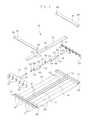
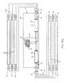
- FIG. 1is an exploded perspective view of one embodiment of a light fixture for use in an apparatus and method according to the invention
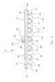
- FIG. 2is an assembled perspective view of the light fixture of FIG. 1 ;
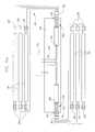
- FIG. 3is an end view of the light fixture of FIG. 1 ;
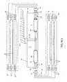
- FIG. 4is a perspective view from below the light fixture of FIG. 1 , with the detachable power pack separated from the body of the light fixture;
- FIG. 5is a perspective view from the side of the light fixture of FIG. 1 , with the detachable power pack separated from the body of the light fixture;
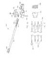
- FIGS. 6( a )- 6 ( c )are circuit diagrams for light fixtures according to the invention having detachable ballast assemblies with hard-wired, armored whip, and modular connector input power configurations, respectively;
- FIGS. 7( a )- 7 ( e )are circuit diagrams for light fixtures according to the invention having detachable ballast assemblies with normal ballast factor, low ballast factor, high ballast factor, dual switch/high ballast factor, and battery backup/high ballast factor configurations, respectively;
- FIGS. 8( a )- 8 ( c )are perspective views of exemplary modular power supply cords for use according to the invention.
- FIG. 9presents plan views of the components of exemplary power input wiring for use according to the invention.
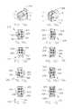
- FIGS. 10( a )- 10 ( j )show exemplary pin assignments for the input power plug and socket connectors in various configurations for use according to the invention.
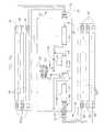
- FIG. 11is a block diagram of a controller and related components in other embodiments of a light fixture according to the invention.
- FIGS. 12( a ) and 12 ( b )are perspective views of modular power supply cords and connectors according to another exemplary embodiment.
- FIG. 13( a )is a detailed perspective view of the connector for a modular power supply cord according to the embodiment shown in FIGS. 12( a ) and 12 ( b ).
- FIG. 13( b )is a detailed perspective view of a power input connector for use with the connector for a modular power supply cord according to the embodiment shown in FIGS. 12( a )- 12 ( b ), and FIG. 13( a ).
- a modular light fixtureincludes a fixture body having a frame with a top a bottom.
- the topdefines a ballast channel and the bottom has a reflector formed from a sheet material.
- a lampholderis mounted to the frame and receives and electrically connects to a fluorescent tube positioned adjacent to the reflector.
- a detachable power packis removable from the top of the frame and includes a ballast channel cover that detachably engages the ballast channel on the top of frame, and a ballast mounted to the ballast channel cover and having power input wiring, and ballast output wiring electrically connected to the lampholder.
- a power input connectorhas a socket portion mounted to the ballast channel cover and electrically connected to the power input wiring of the ballast, and a plug portion connected to a power supply line to provide electrical power from a power source.
- a method of installing lighting in a buildingincludes the following steps. Providing a light fixture having a fixture body with a frame having a top side and a bottom side, the top side defining with a ballast channel, and a lampholder mounted to the frame, where the lampholder includes a lampholder harness connector, and a power pack that includes a ballast channel cover detachably mounted to the top side of the frame and over the ballast channel, and a ballast mounted to the ballast channel cover with power input wiring, and a power input connector having a socket portion mounted within an aperture on the ballast channel cover and electrically connected to the power input wiring of the ballast.
- Another stepincludes connecting the a plug portion of the power input connector to a flexible power supply line electrically connected to the power source.
- Another stepincluded coupling the socket portion to the plug portion on the top side of the frame so that the ballast receives power from the power source without removal of the ballast channel cover.
- a light fixture kitincludes a frame with a top side and a bottom side, and a first raceway and a second raceway on opposite ends of the frame, and a first lampholder mounted to the first raceway and a second lampholder mounted to the second raceway, where the lampholders are electrically connected to a lampholder harness connector.
- a detachable power packincludes a ballast channel cover that detachably engages the top side of the frame, and a ballast mounted to the ballast channel cover, wherein the ballast comprises power input wiring and ballast output wiring, and a socket portion of a power input connector mounted to the ballast channel cover and electrically connected to the power input wiring of the ballast, and a plug portion of the connector electrically connectable to a power source for providing a live load disconnect capable of supplying power to, and removing power from, the ballast without removal of the ballast channel cover.
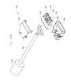
- FIGS. 1-5show various views of an exemplary fluorescent tube light fixture 10 for use in a method and apparatus according to the invention.
- the fixture 10consists generally of a fixture body 66 and a detachable power pack 64 .
- the fixture body 66preferably includes a pair of raceways 12 connected by a ballast channel 14 to form a generally I-frame configuration.
- Each raceway 12is preferably enclosed with a raceway cover 16 , so that the raceway 12 and raceway cover 16 together form a raceway channel 18 , as shown in FIGS. 2-3 .
- Each end of each raceway 12preferably includes a suspension point 68 , for suspending the light fixture 10 above an area to be illuminated, for example using one or more chains connected between the suspension points 68 and the ceiling.
- the suspension points 68are preferably located at or near the corners of the fixture, to ensure that the suspension hardware does not interfere with maintenance of the light fixture including but not limited to replacement of the detachable power pack 64 .
- Each light reflector 22is secured to each of the raceways 12 such as by rivets, bolts, screws or the like. Six reflectors are shown in the drawings, however, it should be noted that any number of light reflectors can be used with the present invention.
- Each light reflector 22can be fabricated from a single piece of material or can be fabricated of individual pieces of material. Any exposed edges of the light reflectors 22 are preferably folded back (hemmed) to reduce sharp edges and improve safety.
- each light reflector 22defines a reflector channel 24 adapted to house a lamp 30 (not shown in FIGS. 1-5 ), which is preferably a fluorescent tube lamp.
- a light fixture according to the inventioncould be used with other types of discharge lamps, such as a metal halide or sodium lamp.
- the fixture body 66includes lampholder harnesses 26 housed in the two raceway channels 18 at the opposite ends of the light fixture.
- Each lampholder harness 26includes one or more lampholders (sockets) 28 and a lampholder harness connector 32 .
- Each lampholder 28preferably extends through a corresponding aperture 34 in a raceway 12 adjacent to the end of a reflector channel 24 .
- a single fluorescent tube lampextends between a pair of lampholders 28 at opposite ends of each reflector channel 24 .
- the detachable power pack 64 of the light fixture 10preferably includes a ballast channel cover 36 , one or more ballasts 48 , power input wiring 54 , a modular power input connector 56 , ballast output wiring 58 , and a modular ballast output connector 60 .
- the detachable power pack 64is preferably detachable from the light fixture body 66 without the use of tools, and without any interference from the suspension hardware.
- the ballast channel cover 36 of the detachable power pack 64engages the ballast channel 14 of the fixture body 66 to define a ballast chamber 38 .
- the ballast channel cover 36preferably includes cover clip portions 41 which mate with corresponding body clip portions 40 to detachably attach the ballast channel cover 36 to the ballast channel 14 .
- the clipsprovide an interference or frictional fit that preferably can be separated without the use of tools. However, this is not required, and other means, such as screws, could be used to detachably attach the detachable power pack 64 to the fixture body 66 .
- the ballast channel coverpreferably includes a power line connector aperture 42 adapted to receive a modular power input connector 56 , and a feature connector aperture 43 adapted to receive a feature connector (not shown).
- the modular power input connector 56is preferably a polarized modular power input socket 210 configured for the available electrical power supply voltage and configuration, as discussed in more detail below in reference to FIGS. 9-10 . However, this is not required, and other methods can be used to supply electrical power to the fixture, as discussed in more detail below in reference to FIGS. 6( a )- 6 ( c ).
- the exemplary detachable power pack 64 of the light fixture 10includes two ballasts 48 , for example a model 49776 electronic ballast available from GE Lighting of Cleveland, Ohio. However, this is not required, and other makes and models of ballasts can be employed with the present invention. Further, while the exemplary light fixture 10 includes two ballasts 48 , a greater or lesser number of ballasts 48 can be used.
- Each ballast 48has a first (input) end 50 and a second (output) end 52 .
- Power input wiring 54electrically connects the modular power input connector 56 to the first end 50 of each ballast 48 .
- the modular power input connector 56mates with a modular power cord assembly 180 supplying electrical power.
- the modular power cord assembly 180is preferably quickly and easily disconnected from the modular power input connector 56 without the use of tools, in order to verifiably and positively remove electrical power from the fixture to reduce the risk of electrical shock during maintenance.
- Ballast output wiring 58electrically connects the second (output) end 52 of each ballast 48 to a modular ballast output connector 60 .
- the modular ballast output connector 60mates with a corresponding lampholder harness connector 32 .
- the modular ballast output connector 60is preferably quickly and easily disconnected from the lampholder harness connector 32 without the use of tools.
- Each ballast 48is fastened to the ballast channel cover 36 , for example using threaded fasteners to engage mounting ears 62 on each ballast 48 through holes in the ballast channel cover 36 .
- threaded fastenersare not required and other means can be utilized to fasten each ballast 48 to the ballast channel cover 36 , such as adhesives or interference mounting techniques.
- the modular power input connector 56preferably extends through the aperture 42 for connection to a modular power cord assembly 180 (not shown in FIGS. 1-5 ).
- the ballast channel cover 36is preferably positioned above the ballast 48 , with good thermal contact between the ballast 48 and ballast channel cover 36 , so waste heat generated by the ballast 48 conducts upwardly to the ballast channel cover 36 .
- the ballast channel cover 36is preferably positioned at the top of the fixture 10 , and exposed to air circulation so waste heat from the ballast can radiate away from the light fixture.
- each ballast 48is housed in the ballast chamber 38 , and oriented so that the modular ballast output connectors 60 of the power pack 46 can mate with the modular lampholder harness connectors 32 of the lampholder harnesses 26 .
- Suitable mating modular ballast output connectors 60 and modular lampholder harness connectors 32are a male and female connector pair available as models 231-604 and 231-104/02600 from Wago Corp. of Germantown, Wis. However, this is not required and other types, makes and models of mating modular connectors can be used with the present invention.
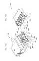
- FIGS. 4 and 5are perspective views of the light fixture of FIG. 1 , with the detachable power pack 64 separated from the fixture body 66 of the light fixture 10 .
- the following discussion of exemplary methods for modifying or servicing a light fixture according to another aspect of the inventionis by way of explanation, and is not necessarily a limitation on the scope of the invention as defined by the claims.
- Replacing the detachable power pack 64 in a light fixture 10for example to change the ballast characteristics in response to changing light requirements or to service a failed ballast, is straightforward and does not necessarily require a high level of skill or the use of tools.
- the modular power cord 180is disconnected from the modular power input connector 56 , thereby positively and verifiably cutting off electrical power from the light fixture 10 to improve the safety of the procedure.
- the old detachable power pack 64is separated from the body 66 of the light fixture by uncoupling the cover clip portions 41 from the body clip portions 40 , and by disconnecting the modular ballast output connectors 60 from their corresponding lampholder harness connectors 32 . The old power pack 64 can then be set aside for eventual disposal or repair.
- the ballast output connectors 60 on the new power pack 64are mated with their corresponding lampholder harness connectors 32 .
- the new power pack 64is detachably fastened to the body 66 of the light fixture by coupling the cover clip portions 41 with the body clip portions 40 .
- modular power cord 180is reconnected to the modular power input connector 56 to restore power to the light fixture 10 for normal operation.
- the present inventioncan be employed with other fixtures, and the invention is not limited to the light fixture shown and described herein.
- another fluorescent tube light fixture embodiment in which the present invention can be employedis that shown and described in U.S. Pat. No. 6,585,396, which is hereby incorporated by reference.
- FIGS. 6( a )- 6 ( c )are circuit diagrams for light fixtures according to the invention having detachable ballast assemblies with alternative input power configurations.
- a variety of alternative input power configurationsare preferably provided to allow a light fixture according to the invention to be used with a variety of available power sources. These alternative input power configurations can be classified generally into “hard wire” configurations, and “modular” configurations.
- a light fixture according to the inventioncan include either input power configuration.
- FIGS. 6( a ) and 6 ( b )show examples of hard wire input power configurations.
- the detachable power pack 64 of FIG. 6( a )includes a hard wire power supply connector 152 .
- the hard wire power supply connector 152represents a connection which is hard wired directly to a branch circuit in the building, for example by an electrician.
- the detachable power pack 64 of FIG. 6( b )includes one type of hard wire power supply connector, an armored whip power supply line 154 .
- the detachable power pack 64 of FIG. 6( c )includes a modular wiring system power supply line 156 .
- An alternative, “daisy chain” modular wiring system power supply lineis described, for example, in U.S. Pat. No. 6,746,274, the contents of which are incorporated by reference.
- FIGS. 6( a )- 6 ( c )show specific combinations of input power configurations with particular types of ballasts, these specific combinations are not required. It should be understood that any of these input power configurations can be used with a light fixture according to the invention, as appropriate for the environment in which the light fixture is to be installed. It should also be understood that any of these power supply configurations can be used with any type of ballast, not just the particular types of ballasts shown in FIGS. 6( a )- 6 ( c ).
- FIGS. 7( a )- 7 ( e )are circuit diagrams for light fixtures according to the invention having detachable ballast assemblies with alternative ballast configurations.
- a variety of alternative ballast configurationscan allow a light fixture according to the invention to provide a wider variety of light levels at varying power consumption levels.
- the detachable power pack of FIG. 7( a )is a high ballast factor detachable power pack 160 that includes a high ballast factor ballast 162 .
- the detachable power pack of FIG. 7( b )is a normal ballast factor detachable power pack 164 that includes a normal ballast factor ballast 166 .
- the detachable power pack of FIG. 7( c )is a low ballast factor detachable power pack 168 that includes a low ballast factor ballast 170 .
- the detachable power pack of FIG. 7( d )is a dual switched detachable power pack 172 that includes two high ballast factor ballasts 162 that receive independent power on separate lines from the modular power input connector 56 .
- the detachable power pack of FIG. 7( e )is a battery backup detachable power pack 174 that includes battery backup circuitry 176 , a battery backup ballast 178 , and two high ballast factor ballasts 162 .
- the battery backup ballast 178can supply lighting in the event of a failure of the main electrical supply, for example in the case of a natural disaster or fire.
- FIG. 8( a )shows a modular power cord assembly 180 having a first end that terminates in a polarized modular power supply plug, and a second end that terminates in a conventional power plug 182 .
- the modular power cord assembly 180includes a suitable length of conventional insulated power cord 181 with 3 or 4 insulated conductors surrounded by an insulated jacket.
- the power cord 181can be any standard electrical power cord having suitable power handling and other specifications, for example 18 gauge 3-conductor or 18 gauge 4-conductor power cord can be used.
- a variety of cord lengthsfor example from 3′ to 35′ in length, are kept in stock, allowing the appropriate cord length to be chosen from stock at the time the light fixture is installed, without requiring any delay for custom manufacturing of a modular power supply cord having the appropriate length.
- the polarized modular power supply plugis preferably a 6-pin “Mate-N-Lock” plug connector of the type sold by the AMP division of Tyco Electronics of Harrisburg, Pa. However, this is not required and other types, makes and models of modular power supply connectors can be used with the present invention.
- the polarized modular power supply plugpreferably includes strain relief, for example two strain relief pieces 184 and a plastic insert 185 (such as AMP P/N 640715-1), and a plug body 188 .
- the strain relief 184 , plastic insert 185 , and plug body 188can be held together with screws 186 , such as #6 ⁇ 5 ⁇ 8′′ sheet metal screws.
- the plug body 188has six positions for holding electrical pins, although a plug body having a greater or lesser number of pin positions could be used. A short portion of the insulation is stripped from the end of each conductor in the electrical cord 181 , and an electrical pin is electrically and mechanically connected to the stripped portion. The electrical pins and attached conductors are then inserted into specific pin positions in the plug body 188 to form a polarized modular power supply plug 158 , as discussed in more detail below in reference to FIGS. 10( a )- 10 ( j ).
- the “extra long” electrical pin 190 used for the green (safety ground) lineis preferably slightly longer than the “standard length” electrical pins 192 used for the black (power supply or “hot”), white (power return or neutral), and red (switched power) lines. This helps ensure that the safety ground connection is made first and broken last when the plug 158 is inserted into or removed from its corresponding socket.
- a suitable extra long electrical pin 190 for the safety groundwould be AMP PN 350669, and a suitable standard length electrical pin 192 for the other lines would be AMP PN 350547-1.
- the conventional power plug 182can be any standard electrical plug configuration, such as a NEMA 5, NEMA L5, NEMA L7, NEMA 6, or NEMA L6 plug.
- a variety of plug configurationsare kept in stock, allowing the appropriate plug configuration to be chosen from stock at the time the light fixture is installed, without requiring any delay for custom manufacturing of a modular power supply cord having the appropriate plug configuration.
- FIG. 8( b )shows an alternative modular power cord assembly 198 having a first end that terminates in a polarized modular power supply plug, and a second end that terminates in stripped conductors 196 , preferably about 3 ⁇ 8′′ in length.
- the modular power cord assembly 198is similar in construction to the modular power cord assembly 180 , except that the modular power cord assembly 198 terminates in stripped conductors 196 that can be used, for example, to hardwire the fixture to building power, and the modular power cord assembly 198 is wired for “universal” application.
- FIG. 8( c )shows a “dual switch” modular power cord assembly 199 that is otherwise similar in construction to the modular power cord assembly 198 .
- FIG. 9shows exemplary power input wiring 54 for a detachable power pack in a light fixture according to the invention.
- the exemplary power input wiring 54includes at least 3 insulated conductors, including a safety ground (green) wire 200 , a power return (white) wire 202 , and a power supply (black) wire 204 .
- the power input wiring 54may also include a switched power (red) wire 206 , and a second power supply (black) wire 204 .
- Each conductoris made of a suitable length of insulated wire, for example UL 1015 18 AWG wire rated for 105° C. and 600V can be used.
- a modular power input connector 56which is preferably a polarized modular power input socket 210 such as a 6 -pin “Mate-N-Lock” socket connector of the type sold by the AMP division of Tyco Electronics of Harrisburg, Pa.
- the polarized modular power input socket 210includes a socket body 208 having six positions for holding single conductor sockets, although a socket having a greater or lesser number of single conductor socket positions could be used.
- a short portion of the insulationis stripped from the end of each conductor, and a single conductor socket 193 , for example AMP PN 350550-1, is electrically and mechanically connected to the stripped portion, for example by crimping and/or soldering.
- the single conductor socket 193 and attached conductorare then inserted into a specific single conductor socket position in the socket body 208 to form the polarized modular power input socket 210 , as discussed in more detail below in reference to FIGS. 10( a )- 10 ( j ).
- FIGS. 10( a )- 10 ( j )shows exemplary pin assignments for the input power plug and socket connectors in various configurations of a detachable power pack for use in a light fixture according to the invention. However, these pin assignments are not required, and other pin assignments could be used.
- FIGS. 10( a ) and 10 ( b )illustrate a convention for numbering the pins ( 1 - 6 ) in the input power plug and socket connectors.
- FIGS. 10( c ) and 10 ( d )illustrate an exemplary 120V power supply configuration.
- the exemplary 120V power supply configurationuses a 120V modular power supply plug 212 along with a 120V modular power input socket 220 .
- the plug 212 and socket 220each include at least a safety ground (green) wire 200 , a power return (white) wire 202 , and a power supply (black) wire 204 located at specific positions in plug head 188 and socket head 208 , respectively.
- the plug 212 and socket 220When used in a 120V dual-switched configuration, the plug 212 and socket 220 also include a second power (red) wire 206 .
- FIGS. 10( e ) and 10 ( f )illustrate an exemplary 277V power supply configuration.
- the exemplary 277V power supply configurationuses a 277V modular power supply plug 214 along with a 277V modular power input socket 222 .
- the 277V plug 214 and the 277V socket 222each include at least a safety ground (green) wire 200 , a power return (white) wire 202 , and a power supply (black) wire 204 .
- the safety ground (green) wire 200 and the power return (white) wire 202 of the 277V configurationare at the same pin positions as in the 120V configuration, however the power supply (black) wire 204 is at a different pin position.
- the plug 214 and socket 222also include a second or switched power (red) wire 206 .
- FIGS. 10( g ) and 10 ( h )illustrate an exemplary 347/480V poser supply configuration.
- the exemplary 347/480V power supply configurationuses a 347/480V modular power supply plug 216 along with a 347/480V modular power input socket 224 .
- the 347/480V plug 216 and the 347/480V socket 224each include at least a safety ground (green) wire 200 , a power return (white) wire 202 , and a power supply (black) wire 204 .
- the safety ground (green) wire 200 and the power return (white) wire 202 of the 277V configurationare at the same pin positions as in the 120V and 277V configurations, however the power supply (black) wire 204 is at a different pin position.
- the plug 216 and socket 224When used in a 347/480V dual-switched configuration, the plug 216 and socket 224 also include a second or switched power (red) wire 206 .
- FIGS. 10( i ) and 10 ( j )illustrate an exemplary “UNV” or “universal” power supply configuration.
- the exemplary “UNV” or “universal” power supply configuration ofuses a UNV modular power supply plug 218 along with a UNV modular power input socket 226 .
- a light fixture wired with the UNV power supply socket configurationcan be used with either a 120V supply cord or a 277V supply cord.
- a light fixture wired with the 120v power supply socket configurationcan be used with either a 120V supply cord or a UNV supply cord.
- a light fixture wired with the 277v power supply socket configurationcan be used with either a 277V supply cord or a UNV supply cord.
- the UNV plug 218 and the UNV socket 226each include at least a safety ground (green) wire 200 and a power return (white) wire 202 , in the same pin and socket positions as the 120V, 277V, and 347/480V configurations.
- the UNV plug 218 and the UNV socket 226each include two power supply (black) wires 204 , one power supply (black) wire 204 at each of the two pin positions used for the power supply (black) wire 204 in the 120V and 277V configurations.
- the plug 218 and socket 226When used in a 120V or 277V dual-switched configuration, the plug 218 and socket 226 also include a second or switched power (red) wire 206 .
- FIGS. 12( a ) and 12 ( b )another polarized modular power supply connector (e.g. power input connector) is shown according to an exemplary embodiment and includes a plug portion 380 (the corresponding socket portion is shown in FIG. 13( b )).
- the polarized modular power supply plugis preferably a five-pin “Winsta” type plug-in connector of the type sold by the WAGO Corporation of Germantown, Wis. However, this is not required and other types, makes and models of modular power supply connectors can be used with the present invention.
- the plug portion 380 of the polarized modular power supply connectorpreferably includes strain relief, for example two strain relief pieces 384 , and a plug body 388 .
- the strain relief 384 and plug body 388can be held together with screws, such as #6 ⁇ 5 ⁇ 8′′ sheet metal screws, or other suitable fastener.
- the plug body 388has ten positions for holding electrical wires, although a plug body having a greater or lesser number of wire positions could be used (e.g., such as eight wire positions).
- a short portion of the insulationis stripped from the end of each conductor in the electrical cord 381 and are then inserted into specific wire positions in the plug body 388 to form a polarized modular power supply connector, as discussed in more detail below in reference to FIGS. 13( a ) and 13 ( b ).
- Electrical cord 381provides a flexible electrical power supply line that is connectable with a power source in a building through a connector 383 (shown in FIG. 12( b )) or by hardwiring individual conductors (shown in FIG. 12( a )).
- a plurality of electrical cords 381are disposed at locations throughout a building at locations corresponding to light fixture installations and have one end pre-wired to a power supply within the building and the other end pre-wired to a plug (or socket) portion, so that the light fixtures may be pre-assembled at a factory with a socket (or plug) portion of the connector within the ballast cover, and then shipped to the building, installed at the appropriate locations in the building, and then electrically connected simply by connecting the socket and plug portions of the connector for each light fixture.
- the plug portion 380 of the modular power supply connectoris shown by way of example to include five conductive projections (e.g. pins, posts, pegs, prongs, etc.) 390 , 392 , 394 , 396 and 398 .
- any number of projectionssuch as four, eight, etc. may be provided to suit an intended number of conductors for a particular lighting application.
- Each of the projections 390 , 392 , 394 , 396 and 398are shown to include a substantially square cross section with a hollow interior.
- the projectionsare also shown to include one or more extensions (e.g.
- “outside” projections 390 and 398are shown to include an extension 400 extending from a mid section of the projections, and “inside” projections 392 and 396 are each shown to have a pair of extensions, 402 and 404 , extending from a top and bottom of the projection respectively and parallel to one another, and “center” projection 394 include an extension 406 extending from a top side of the projection.
- the extensionsmay be arranged in any suitable pattern or arrangement to ensure proper orientation and mating of the plug portion 380 and the socket portion 456 of the power input connector.
- Each of the projections and their extension(s)are configured to be received in a mating conductive recess or socket, shown as conductor sockets 490 , 492 , 494 , 496 and 498 in the socket portion 456 of the connector (e.g. power input connector—shown in FIG. 13( b )).
- Each of conducting sockets 490 , 492 , 494 , 496 and 498includes a cross sectional shape corresponding to the pattern of extensions provided on the projections 390 , 392 , 394 , 396 and 398 , and is electrically and mechanically connected to power input wiring 54 (in the manner as shown in FIG. 4) .
- socket portion 456provides another embodiment of a modular connector portion that extends through, and is retained within, aperture 42 in the ballast channel cover 36 for use in making a rapid connection, and a rapid “live-load” disconnection, of the plug portion 380 from the socket portion 456 without removal of the ballast channel cover 36 or other portion of the fixture.
- a modular light fixturecan include a controller 80 , for example a microprocessor or microcontroller of the types known in the art.
- the controller 80may include suitable non-volatile program memory, for example read-only memory (ROM) such as an electrically programmable read only memory (EPROM or EEPROM).
- ROMread-only memory
- EPROMelectrically programmable read only memory
- EEPROMelectrically programmable read only memory
- the controller 80may also include suitable random access memory, for storage of dynamic state variables such as environmental signals and current day/time.
- the light fixturepreferably includes a power source 82 , such as an electrical connector which is connected to line voltage during normal operation, able to deliver electrical power to the controller 80 through a controller power supply line 84 .
- a power source 82such as an electrical connector which is connected to line voltage during normal operation, able to deliver electrical power to the controller 80 through a controller power supply line 84 .
- the light fixture according to the inventionpreferably includes a plurality of independently controllable lamp circuits.
- the block diagram of FIG. 6shows a light fixture with a first independently controllable lamp circuit that includes lamp one 102 and a second independently controllable lamp circuit that include lamp two 106 .
- thisis not required and a single lamp circuit can be used.
- Each independently controllable lamp circuitpreferably includes a ballast and an optional switch.
- lamp circuit for lamp one 102includes a switch one 86 that receives electrical power from the power source 82 on a power supply line 88 .
- the switch one 86delivers electrical power to a ballast one 94 on a switched power supply line 96
- the ballast one 94provides power to the lamp one 102 on a ballasted power supply line 104 .
- the lamp circuit for lamp two 106preferably includes a corresponding switch two 90 that receives electrical power from the power source 82 on a power supply line 92 .
- the switch two 90delivers electrical power to a ballast two 98 on a switched power supply line 100 , and the ballast two 98 provides power to the lamp two 106 on a ballasted power supply line 108 .
- Each switch in a lamp circuitsuch as switch one 86 and switch two 90 , is preferably adapted to be placed into either an open condition (where the switch is an electrical open circuit through which no current flows) or in a closed condition (where the switch is an electrical closed circuit through which current can flow).
- a mechanical relay switchinstead of a solid state switch, can be used so that essentially no trickle current passes through the switch when the switch is in an open condition.
- each switchis preferably independently controllable by the controller 80 .
- the controller 80can be connected to switch one 86 by a switch control line 110 , whereby the controller can place switch one 86 into either a closed or an open condition.
- the controller 80can be connected to switch two 90 by a switch control line 112 , whereby the controller can place switch two 90 into either a closed or an open condition.
- Each ballast in a lamp circuitis preferably dimmable to allow the light output from its lamp to be adjusted by the controller 80 .
- the controller 80can be connected to ballast one 94 by a ballast control line 114 , so the controller can adjust the power output of ballast one 94 to adjust the light output from lamp one 102 .
- the controller 80can be connected to ballast two 98 by a ballast control line 116 , so the controller can adjust the power output of ballast two 98 to adjust the light output from lamp two 106 .
- the light fixturecan include one or more sensors to provide information about the environment in which the light fixture operates.
- the fixturecan include an ambient light sensor 120 providing an ambient light signal to the controller 80 on an ambient light signal line 122 .
- the controller 80can adjust the light output from the fixture, for example to reduce the artificial light produced by the fixture on a sunny day when ambient light provides adequate illumination, or to increase the artificial light produced by the fixture on a cloudy day when ambient light is inadequate.
- the sensorcan be mounted directly on the light fixture, or it can be mounted elsewhere, such as part of the incoming power cord.
- U.S. Pat. No. 6,746,274the contents of which are incorporated herein by reference, teaches a motion detector built into a modular power cord.
- the fixturecan include a motion sensor 124 providing a motion signal to the controller 80 on an motion signal line 126 .
- the controller 80can turn on the fixture when the motion signal indicates the presence of motion near the fixture.
- the controller 80can turn off the fixture when the motion signal indicates the absence of any motion near the fixture.
- the fixturecan include a temperature sensor 128 providing a temperature signal to the controller 80 on an temperature signal line 130 .
- the temperature signalcan indicate, for example, the air temperature in the vicinity of the fixture.
- the temperature signalcan indicate the temperature of the ballast or other components of the light fixture, so that any temperature rise resulting from abnormal operation or impending failure can be promptly detected to avoid ongoing inefficiency, the possibility of a fire, or a catastrophic failure of the ballast.
- the fixturecan include a proximity sensor 132 providing a proximity signal to the controller 80 on a proximity signal line 134 . Using the proximity signal, the controller 80 can turn on the fixture on or off when the proximity signal indicates the presence or absence of a person or other object near the fixture.
- the fixturecan also include a communicator 136 to allow communication between the controller 80 and an external system (not shown).
- the communicatorcan be, for example, of the type commonly known as X-10.
- the communicator 136can be connected to the controller 80 for bidirectional communication on a communicator signal line 138 .
- the controller 80can receive a command from an external system, for example to dim, turn on, or turn off a lamp, and the controller 80 can acknowledge back to the external system whether or not the command has been performed successfully.
- the external systemcould request the current temperature of the ballast of the fixture, and the controller 80 could reply with that temperature.
- bidirectional communicationis not required and one-way communication could also be used.
- the fixturecould simply receive and execute commands from an external system without providing any confirmation back to the external system as to whether the command was executed successfully or not.
- the fixturecould periodically and automatically transmit its status information to an external system, without requiring any request from the external system for the status information.
- the fixturecan include a smoke detector 140 providing a smoke detector signal to the controller 80 on a smoke detector signal line 142 .
- the controller 80can provide a local alarm, for example with a flashing light or a siren, whenever the smoke detector signal indicates the presence of a fire or smoke.
- the controller 80can provide the smoke detector signal to an external system, for example through the communicator 136 , to a security office or fire department.
- the fixturecan include a camera and/or microphone 144 providing a camera/microphone signal to the controller 80 on a camera/microphone signal line 146 .
- the controller 80can provide the camera/microphone signal to an external system, for example through the communicator 136 , to a security office, time-lapse recorder, or supervisory station.
- the fixturecan include an audio output device 148 , for example a speaker.
- the controller 80can drive the audio output device 148 , for example with an audio signal on an audio signal line 150 , to provide an alarm, paging, music, or public address message to persons in the vicinity of the fixture.
- the alarm, paging, music, or public address messagecan be received by the controller 80 via the communicator 136 from an external system, although this is not required and the alarm, paging, music, or public address message may be internally generated.
- the exemplary application of the deviceis in the field of fluorescent lighting, the invention has a much wider applicability.
- the particular materials used to construct the exemplary embodimentsare also illustrative.
- the reflectors in the exemplary embodimentare preferably made of aluminum, other materials having suitable properties could be used. All such modifications, to materials or otherwise, are intended to be included within the scope of the present invention as defined in the appended claims.
- mount and attachinclude embed, glue, join, unite, connect, associate, hang, hold, affix, fasten, bind, paste, secure, bolt, screw, rivet, solder, weld, and other like terms.
- coverincludes envelop, overlay, and other like terms.
Landscapes
- Engineering & Computer Science (AREA)
- General Engineering & Computer Science (AREA)
- Power Engineering (AREA)
- Arrangement Of Elements, Cooling, Sealing, Or The Like Of Lighting Devices (AREA)
Abstract
Description
Claims (20)
Priority Applications (6)
| Application Number | Priority Date | Filing Date | Title |
|---|---|---|---|
| US13/424,056US8337043B2 (en) | 2005-10-03 | 2012-03-19 | Modular light fixture with power pack |
| US13/722,889US8858018B2 (en) | 2005-10-03 | 2012-12-20 | Modular light fixture with power pack |
| US14/483,968US9532410B2 (en) | 2005-10-03 | 2014-09-11 | Modular light fixture with power pack |
| US15/389,880US20170108175A1 (en) | 2005-10-03 | 2016-12-23 | Modular light fixture with power pack |
| US15/860,371US10206251B2 (en) | 2005-10-03 | 2018-01-02 | Modular light fixture with power pack |
| US16/272,754US10660172B2 (en) | 2005-10-03 | 2019-02-11 | Modular light fixture with power pack |
Applications Claiming Priority (3)
| Application Number | Priority Date | Filing Date | Title |
|---|---|---|---|
| US11/242,620US7575338B1 (en) | 2005-10-03 | 2005-10-03 | Modular light fixture with power pack |
| US12/345,443US8136958B2 (en) | 2005-10-03 | 2008-12-29 | Modular light fixture with power pack |
| US13/424,056US8337043B2 (en) | 2005-10-03 | 2012-03-19 | Modular light fixture with power pack |
Related Parent Applications (1)
| Application Number | Title | Priority Date | Filing Date |
|---|---|---|---|
| US12/345,443ContinuationUS8136958B2 (en) | 2005-10-03 | 2008-12-29 | Modular light fixture with power pack |
Related Child Applications (1)
| Application Number | Title | Priority Date | Filing Date |
|---|---|---|---|
| US13/722,889Continuation-In-PartUS8858018B2 (en) | 2005-10-03 | 2012-12-20 | Modular light fixture with power pack |
Publications (2)
| Publication Number | Publication Date |
|---|---|
| US20120182729A1 US20120182729A1 (en) | 2012-07-19 |
| US8337043B2true US8337043B2 (en) | 2012-12-25 |
Family
ID=40721464
Family Applications (2)
| Application Number | Title | Priority Date | Filing Date |
|---|---|---|---|
| US12/345,443Expired - Fee RelatedUS8136958B2 (en) | 2005-10-03 | 2008-12-29 | Modular light fixture with power pack |
| US13/424,056Expired - Fee RelatedUS8337043B2 (en) | 2005-10-03 | 2012-03-19 | Modular light fixture with power pack |
Family Applications Before (1)
| Application Number | Title | Priority Date | Filing Date |
|---|---|---|---|
| US12/345,443Expired - Fee RelatedUS8136958B2 (en) | 2005-10-03 | 2008-12-29 | Modular light fixture with power pack |
Country Status (1)
| Country | Link |
|---|---|
| US (2) | US8136958B2 (en) |
Cited By (41)
| Publication number | Priority date | Publication date | Assignee | Title |
|---|---|---|---|---|
| US20130182422A1 (en)* | 2012-01-17 | 2013-07-18 | Joseph Guilmette | Multiple-mode integrated track fixture for high efficiency tubular lamps |
| USD699179S1 (en) | 2013-06-12 | 2014-02-11 | Journée Lighting, Inc. | Field replaceable power supply cartridge |
| US8729833B2 (en) | 2012-03-19 | 2014-05-20 | Digital Lumens Incorporated | Methods, systems, and apparatus for providing variable illumination |
| US8754589B2 (en) | 2008-04-14 | 2014-06-17 | Digtial Lumens Incorporated | Power management unit with temperature protection |
| US8805550B2 (en) | 2008-04-14 | 2014-08-12 | Digital Lumens Incorporated | Power management unit with power source arbitration |
| US8823277B2 (en) | 2008-04-14 | 2014-09-02 | Digital Lumens Incorporated | Methods, systems, and apparatus for mapping a network of lighting fixtures with light module identification |
| US8841859B2 (en) | 2008-04-14 | 2014-09-23 | Digital Lumens Incorporated | LED lighting methods, apparatus, and systems including rules-based sensor data logging |
| US8866408B2 (en) | 2008-04-14 | 2014-10-21 | Digital Lumens Incorporated | Methods, apparatus, and systems for automatic power adjustment based on energy demand information |
| US8954170B2 (en) | 2009-04-14 | 2015-02-10 | Digital Lumens Incorporated | Power management unit with multi-input arbitration |
| US9014829B2 (en) | 2010-11-04 | 2015-04-21 | Digital Lumens, Inc. | Method, apparatus, and system for occupancy sensing |
| USD732234S1 (en) | 2014-03-26 | 2015-06-16 | Elite Lighting | Body for light fixture |
| US9072133B2 (en) | 2008-04-14 | 2015-06-30 | Digital Lumens, Inc. | Lighting fixtures and methods of commissioning lighting fixtures |
| US9241401B2 (en) | 2010-06-22 | 2016-01-19 | Express Imaging Systems, Llc | Solid state lighting device and method employing heat exchanger thermally coupled circuit board |
| US9445485B2 (en) | 2014-10-24 | 2016-09-13 | Express Imaging Systems, Llc | Detection and correction of faulty photo controls in outdoor luminaires |
| US9447949B2 (en) | 2014-04-25 | 2016-09-20 | Elite Lighting | Light fixture |
| US9510426B2 (en) | 2011-11-03 | 2016-11-29 | Digital Lumens, Inc. | Methods, systems, and apparatus for intelligent lighting |
| US9565782B2 (en) | 2013-02-15 | 2017-02-07 | Ecosense Lighting Inc. | Field replaceable power supply cartridge |
| US9568665B2 (en) | 2015-03-03 | 2017-02-14 | Ecosense Lighting Inc. | Lighting systems including lens modules for selectable light distribution |
| US9572230B2 (en) | 2014-09-30 | 2017-02-14 | Express Imaging Systems, Llc | Centralized control of area lighting hours of illumination |
| USD782093S1 (en) | 2015-07-20 | 2017-03-21 | Ecosense Lighting Inc. | LED luminaire having a mounting system |
| USD782094S1 (en) | 2015-07-20 | 2017-03-21 | Ecosense Lighting Inc. | LED luminaire having a mounting system |
| USD785218S1 (en) | 2015-07-06 | 2017-04-25 | Ecosense Lighting Inc. | LED luminaire having a mounting system |
| US9651232B1 (en) | 2015-08-03 | 2017-05-16 | Ecosense Lighting Inc. | Lighting system having a mounting device |
| US9651227B2 (en) | 2015-03-03 | 2017-05-16 | Ecosense Lighting Inc. | Low-profile lighting system having pivotable lighting enclosure |
| US9651216B2 (en) | 2015-03-03 | 2017-05-16 | Ecosense Lighting Inc. | Lighting systems including asymmetric lens modules for selectable light distribution |
| US9673582B2 (en) | 2012-01-17 | 2017-06-06 | Joseph Guilmette | Modular housing and track assemblies for tubular lamps |
| USD790753S1 (en) | 2016-05-17 | 2017-06-27 | Elite Lighting | Body for a light fixture |
| US9746159B1 (en) | 2015-03-03 | 2017-08-29 | Ecosense Lighting Inc. | Lighting system having a sealing system |
| USD797349S1 (en) | 2016-05-17 | 2017-09-12 | Elite Lighting | Ballast room cover for a light fixture |
| US9869450B2 (en) | 2015-02-09 | 2018-01-16 | Ecosense Lighting Inc. | Lighting systems having a truncated parabolic- or hyperbolic-conical light reflector, or a total internal reflection lens; and having another light reflector |
| US9924576B2 (en) | 2013-04-30 | 2018-03-20 | Digital Lumens, Inc. | Methods, apparatuses, and systems for operating light emitting diodes at low temperature |
| US10164374B1 (en) | 2017-10-31 | 2018-12-25 | Express Imaging Systems, Llc | Receptacle sockets for twist-lock connectors |
| US10264652B2 (en) | 2013-10-10 | 2019-04-16 | Digital Lumens, Inc. | Methods, systems, and apparatus for intelligent lighting |
| US10352511B2 (en) | 2016-03-04 | 2019-07-16 | Energy Bank Incorporated | Lighting fixture |
| US10477636B1 (en) | 2014-10-28 | 2019-11-12 | Ecosense Lighting Inc. | Lighting systems having multiple light sources |
| US10485068B2 (en) | 2008-04-14 | 2019-11-19 | Digital Lumens, Inc. | Methods, apparatus, and systems for providing occupancy-based variable lighting |
| US10830419B2 (en) | 2015-03-20 | 2020-11-10 | Energy Bank Incorporated | Lighting fixture |
| US10928023B2 (en) | 2016-06-10 | 2021-02-23 | Elite Lighting | High bay light fixture |
| US11306897B2 (en) | 2015-02-09 | 2022-04-19 | Ecosense Lighting Inc. | Lighting systems generating partially-collimated light emissions |
| US11375599B2 (en) | 2017-04-03 | 2022-06-28 | Express Imaging Systems, Llc | Systems and methods for outdoor luminaire wireless control |
| US11653436B2 (en) | 2017-04-03 | 2023-05-16 | Express Imaging Systems, Llc | Systems and methods for outdoor luminaire wireless control |
Families Citing this family (40)
| Publication number | Priority date | Publication date | Assignee | Title |
|---|---|---|---|---|
| US8858018B2 (en) | 2005-10-03 | 2014-10-14 | Orion Energy Systems, Inc. | Modular light fixture with power pack |
| US8136958B2 (en)* | 2005-10-03 | 2012-03-20 | Orion Energy Systems, Inc. | Modular light fixture with power pack |
| US8344665B2 (en) | 2008-03-27 | 2013-01-01 | Orion Energy Systems, Inc. | System and method for controlling lighting |
| US8884203B2 (en) | 2007-05-03 | 2014-11-11 | Orion Energy Systems, Inc. | Lighting systems and methods for displacing energy consumption using natural lighting fixtures |
| US8376600B2 (en)* | 2007-06-29 | 2013-02-19 | Orion Energy Systems, Inc. | Lighting device |
| US8406937B2 (en) | 2008-03-27 | 2013-03-26 | Orion Energy Systems, Inc. | System and method for reducing peak and off-peak electricity demand by monitoring, controlling and metering high intensity fluorescent lighting in a facility |
| US8450670B2 (en)* | 2007-06-29 | 2013-05-28 | Orion Energy Systems, Inc. | Lighting fixture control systems and methods |
| US8866582B2 (en) | 2009-09-04 | 2014-10-21 | Orion Energy Systems, Inc. | Outdoor fluorescent lighting fixtures and related systems and methods |
| US8476565B2 (en) | 2007-06-29 | 2013-07-02 | Orion Energy Systems, Inc. | Outdoor lighting fixtures control systems and methods |
| US8729446B2 (en) | 2007-06-29 | 2014-05-20 | Orion Energy Systems, Inc. | Outdoor lighting fixtures for controlling traffic lights |
| US8586902B2 (en) | 2007-06-29 | 2013-11-19 | Orion Energy Systems, Inc. | Outdoor lighting fixture and camera systems |
| US8445826B2 (en) | 2007-06-29 | 2013-05-21 | Orion Energy Systems, Inc. | Outdoor lighting systems and methods for wireless network communications |
| US20100246168A1 (en)* | 2009-03-31 | 2010-09-30 | Orion Energy Systems, Inc. | Reflector with coating for a fluorescent light fixture |
| US8896208B2 (en) | 2009-12-31 | 2014-11-25 | Larry N. Shew | Light assembly |
| US9717117B2 (en) | 2009-12-31 | 2017-07-25 | Larry N. Shew | Lighting system and method of deflection |
| US8657474B2 (en)* | 2010-01-05 | 2014-02-25 | Ideal Industries, Inc. | Electrical socket, apparatus and system |
| US20110235317A1 (en)* | 2010-03-26 | 2011-09-29 | Orion Energy Systems, Inc. | Lighting device with throw forward reflector |
| USD623340S1 (en) | 2010-03-26 | 2010-09-07 | Orion Energy Systems, Inc. | Reflector for a lighting fixture |
| US8376583B2 (en) | 2010-05-17 | 2013-02-19 | Orion Energy Systems, Inc. | Lighting system with customized intensity and profile |
| US9625139B2 (en) | 2010-10-09 | 2017-04-18 | Autronic Plastics, Inc. | Modular LED lighting assembly |
| US8604701B2 (en) | 2011-03-22 | 2013-12-10 | Neal R. Verfuerth | Systems and method for lighting aisles |
| US20120320627A1 (en) | 2011-05-17 | 2012-12-20 | Pixi Lighting Llc | Flat panel lighting device and driving circuitry |
| US8956013B1 (en) | 2012-03-13 | 2015-02-17 | Larry N. Shew | LED light troffer/fixture assembly |
| US9729211B2 (en)* | 2012-11-19 | 2017-08-08 | Bose Corporation | Proximity based wireless audio connection |
| US9500328B2 (en) | 2013-04-17 | 2016-11-22 | Pixi Lighting, Inc. | Lighting assembly |
| US9546781B2 (en) | 2013-04-17 | 2017-01-17 | Ever Venture Solutions, Inc. | Field-serviceable flat panel lighting device |
| US9476552B2 (en) | 2013-04-17 | 2016-10-25 | Pixi Lighting, Inc. | LED light fixture and assembly method therefor |
| US10386027B1 (en) | 2013-09-13 | 2019-08-20 | Clear-Vu Lighting Llc | Pathway lighting system for tunnels |
| USD756016S1 (en) | 2014-02-28 | 2016-05-10 | Ip Holdings, Llc | Horticulture grow light housing |
| US9909748B2 (en) | 2014-05-02 | 2018-03-06 | Clear-Vu Lighting Llc | LED light fixture for use in public transportation facilities |
| USD757325S1 (en) | 2014-07-11 | 2016-05-24 | Ip Holdings, Llc | Light fixture |
| USD757326S1 (en) | 2014-07-11 | 2016-05-24 | Ip Holdings, Llc | Fluorescent light fixture |
| USD761477S1 (en)* | 2014-10-28 | 2016-07-12 | RAB Lighting Inc. | High bay LED light rail |
| USD757327S1 (en) | 2014-12-12 | 2016-05-24 | Ip Holdings, Llc | Fluorescent light fixture |
| US9557022B2 (en) | 2015-04-30 | 2017-01-31 | Ever Venture Solutions, Inc. | Non-round retrofit recessed LED lighting fixture |
| USD770671S1 (en) | 2015-09-03 | 2016-11-01 | Ip Holdings, Llc | Horticulture grow light |
| US10393352B2 (en) | 2016-10-07 | 2019-08-27 | The Toro Company | Elastomeric retention ring for lamps |
| US11490474B1 (en) | 2019-03-29 | 2022-11-01 | Autronic Plastics, Inc. | Bi-level light fixture for public transportation tunnels |
| USD1027259S1 (en) | 2022-01-28 | 2024-05-14 | RAB Lighting Inc. | High bay light fixture with staggered driver enclosure |
| CN118309978B (en)* | 2024-04-30 | 2025-01-10 | 江苏天白光电有限公司 | Classroom lamp capable of being quickly disassembled and assembled |
Citations (107)
| Publication number | Priority date | Publication date | Assignee | Title |
|---|---|---|---|---|
| US1918126A (en) | 1929-06-24 | 1933-07-11 | Johann G Peterson | Electrical connecter |
| US2306206A (en) | 1940-08-13 | 1942-12-22 | Pye Ltd | Electric coupling |
| US2312617A (en) | 1940-08-20 | 1943-03-02 | Morris B Beck | Fluorescent tube lighting fixture |
| US2403240A (en) | 1943-12-02 | 1946-07-02 | Wheeler Refiector Company | Retaining guard for fluorescent lamps |
| US2619583A (en) | 1947-10-21 | 1952-11-25 | Gen Electric | Luminaire for elongated tubular lamps |
| US2636977A (en) | 1953-04-28 | Safety guard for fluorescent lamps | ||
| US2748359A (en) | 1952-01-24 | 1956-05-29 | Joy Mfg Co | Electrical connector |
| US3247368A (en) | 1963-07-16 | 1966-04-19 | Arnold Company Inc | Fluorescent lighting fixture |
| US3337035A (en) | 1964-12-21 | 1967-08-22 | James A Schoke | Handling protector for u-tubes |
| US3390371A (en) | 1966-06-24 | 1968-06-25 | Daniel Woodhead Company | Cable clamp for electrical wiring device |
| US3571781A (en) | 1968-12-06 | 1971-03-23 | Hubbell Inc Harvey | Plastic cable clamp |
| US4001571A (en) | 1974-07-26 | 1977-01-04 | National Service Industries, Inc. | Lighting system |
| US4144462A (en) | 1977-04-28 | 1979-03-13 | Dual-Lite, Inc. | Emergency lighting fluorescent pack |
| US4146287A (en) | 1977-10-07 | 1979-03-27 | National Service Industries, Inc. | Lighting and power system and connectors therefor |
| US4169648A (en) | 1978-06-01 | 1979-10-02 | Amp Incorporated | Strain relief and back cover for electrical connector |
| US4238815A (en) | 1978-06-29 | 1980-12-09 | Edison Price, Incorporated | Recessed light fixture |
| USD263699S (en) | 1979-08-24 | 1982-04-06 | New Era Products, Inc. | Power cord plug |
| US4363082A (en) | 1980-08-26 | 1982-12-07 | Levolor Lorentzen, Inc. | Panel ceiling and light fixture |
| US4387417A (en) | 1981-12-30 | 1983-06-07 | General Electric Company | Lamp retaining means within luminaire |
| US4435744A (en) | 1981-08-10 | 1984-03-06 | Pauluhn Electric Manufacturing Co., Inc. | Explosion-proof fluorescent light fixture |
| US4443048A (en) | 1981-10-02 | 1984-04-17 | Amp Incorporated | Assembly with verification feature |
| US4544220A (en) | 1983-12-28 | 1985-10-01 | Amp Incorporated | Connector having means for positively seating contacts |
| US4674015A (en) | 1986-05-05 | 1987-06-16 | Smith Daniel R | Fluorescent light fixture with removable ballast |
| US4690476A (en) | 1986-10-30 | 1987-09-01 | Jali Morgenrath | Electrical connector securing system |
| US4701698A (en) | 1980-06-06 | 1987-10-20 | Karlsson Bjoern G | Microprocessor based energy consumption meter |
| US4708662A (en) | 1986-06-20 | 1987-11-24 | Amp Incorporated | Connector assembly with pre-staged terminal retainer |
| US4726780A (en) | 1986-09-19 | 1988-02-23 | Michael Thackeray | Twist-lock female plug adapter |
| US4749941A (en) | 1986-05-20 | 1988-06-07 | Lgz Landis & Gyr Zug Ag | Circuit arrangement for a meter for measuring two electrical quantities |
| US4814954A (en) | 1987-12-24 | 1989-03-21 | Spitz Russell W | Rigid lightweight fluorescent fixture |
| US4834673A (en) | 1987-05-14 | 1989-05-30 | Amp Incorporated | Flat cable power distribution system |
| US4904195A (en) | 1988-06-24 | 1990-02-27 | Michael Thackeray | Twist-lock female-male plug adapter |
| US4907985A (en) | 1989-06-26 | 1990-03-13 | Johnsen Cary T | Safety twist lock connector for an extension power cord |
| US4928209A (en) | 1988-08-31 | 1990-05-22 | Mirrorlite, Inc. | Lighting apparatus |
| US4933633A (en) | 1981-06-09 | 1990-06-12 | Adec, Inc. | Computer controlled energy monitoring system |
| USD311900S (en) | 1988-06-30 | 1990-11-06 | Next, Inc. | Electrical connector for computer power cable |
| US5013253A (en) | 1990-02-20 | 1991-05-07 | Amp Incorporated | Fluorescent light connector assembly |
| US5037325A (en) | 1990-10-05 | 1991-08-06 | Molex Incorporated | Panel mounted electrical connector |
| US5062030A (en) | 1990-12-10 | 1991-10-29 | Figueroa Luisito A | Customized light reflector |
| US5069634A (en) | 1991-01-24 | 1991-12-03 | Chiarolanzio Martin J | Snap lock extension cord and power tool connector |
| US5111370A (en) | 1991-02-21 | 1992-05-05 | Clark Walter B | Device and method for converting a down-light into an up-light |
| USD329919S (en) | 1991-01-15 | 1992-09-29 | Zumtobel Lighting, Inc. | Suspended fluorescent lighting fixture |
| US5192129A (en) | 1990-12-10 | 1993-03-09 | Figueroa Luisito A | Customized light reflector |
| US5274533A (en) | 1991-01-25 | 1993-12-28 | Neary Robert A | Reflector assembly having improved light reflection and ballast access |
| US5315236A (en) | 1991-03-05 | 1994-05-24 | Lee Graham S | Power consumption meter for displaying electric power consumed by appliance and the time period of consumption |
| US5320560A (en) | 1991-08-06 | 1994-06-14 | Woods Wire Products, Inc. | Light-permeable extension cord connector |
| US5342221A (en) | 1993-01-08 | 1994-08-30 | Molex Incorporated | Keying system for electrical connectors |
| US5349289A (en) | 1992-04-27 | 1994-09-20 | Kaise Kabushiki Kaisha | Clamp-on multimeter having a display for indicating the results of a plurality of measurements |
| US5357170A (en) | 1993-02-12 | 1994-10-18 | Lutron Electronics Co., Inc. | Lighting control system with priority override |
| US5371661A (en) | 1992-07-21 | 1994-12-06 | Simpson; Alexander L. | Retro-fit lighting fixture and method of retro-fitting |
| US5377075A (en) | 1994-05-04 | 1994-12-27 | Ml Systems | Ballast cradle and retrofit for fluorescent light conversion |
| US5395264A (en) | 1993-02-05 | 1995-03-07 | Keith; Carlton L. | Electrical connector/adapter |
| US5462452A (en) | 1993-11-22 | 1995-10-31 | Devine; Michael J. | Breakaway extension cord for preventing electrical plug damage |
| USD364478S (en) | 1992-10-20 | 1995-11-21 | Zumtobel Licht Gmbh | Fluorescent lighting fixture |
| US5473522A (en) | 1994-07-25 | 1995-12-05 | Sportlite, Inc. | Modular luminaire |
| USD365409S (en) | 1994-08-04 | 1995-12-19 | Yeou-Jyh Lu | Ceiling mounted light housing |
| US5489827A (en) | 1994-05-06 | 1996-02-06 | Philips Electronics North America Corporation | Light controller with occupancy sensor |
| US5616042A (en) | 1995-06-28 | 1997-04-01 | Raby, Sr.; Frederick R. | Adapter for converting fluorescent light fixtures |
| USD381629S (en) | 1995-05-09 | 1997-07-29 | Sony Corporation | Cable connector assembly |
| US5673022A (en) | 1996-03-27 | 1997-09-30 | Jitendra Ambalal Patel | Motion sensor/photoelectric light sensor plug-in receptacle |
| US5676563A (en) | 1994-09-26 | 1997-10-14 | Sumitomo Wiring Systems, Ltd. | Snow-melting tile wiring unit |
| US5727871A (en) | 1996-06-03 | 1998-03-17 | Kotloff; Ronald F. | Fluorescent lighting fixture |
| US5743627A (en) | 1997-02-25 | 1998-04-28 | Casteel; Joseph M. | Lighting fixture |
| USD395727S (en) | 1997-04-24 | 1998-06-30 | Focal Point Lighting | Fluorescent lighting fixture |
| USD399019S (en) | 1996-04-19 | 1998-09-29 | Zumtobel Licht Gmbh | Fluorescent lighting fixture |
| USD402763S (en) | 1997-03-10 | 1998-12-15 | Vimmerbyb Industrier AB | Light fitting for solaria |
| US5855494A (en) | 1997-05-05 | 1999-01-05 | 3 Com Corp. | Apparatus and method for electrically connecting a plurality of electronic modules |
| US5907197A (en) | 1997-06-30 | 1999-05-25 | Compaq Computer Corporation | AC/DC portable power connecting architecture |
| US5961207A (en) | 1997-06-16 | 1999-10-05 | Petkovic; Peter M. | Trouble light apparatus |
| USD416542S (en) | 1998-12-18 | 1999-11-16 | Hon Hai Precision Ind. Co., Ltd. | Cable connector assembly |
| US6024594A (en) | 1998-01-13 | 2000-02-15 | The Whitaker Corporation | Connector latch with tubular hinge |
| US6059424A (en) | 1996-06-03 | 2000-05-09 | Kotloff; Ronald F. | Fluorescent lighting fixture |
| USD425860S (en) | 1999-01-21 | 2000-05-30 | Sony Corporation | Electric connector |
| US6091200A (en) | 1998-12-17 | 2000-07-18 | Lenz; Mark | Fluorescent light and motion detector with quick plug release and troubleshooting capabilities |
| US6102550A (en) | 1999-02-16 | 2000-08-15 | Photronix, Llc | Bracket assembly for fluorescent lighting fixture having removable, high-frequency power output ballast |
| US6151529A (en) | 1995-02-02 | 2000-11-21 | Hubbell Incorporated | Motion sensing system with adaptive timing for controlling lighting fixtures |
| USD434167S (en) | 1997-10-16 | 2000-11-21 | Artemide S.P.A. | Modular lighting system |
| US6210019B1 (en) | 1998-11-04 | 2001-04-03 | Osram Sylvania Inc. | Method for retrofitting and retrofit kit for fluorescent lighting fixture |
| USD447266S1 (en) | 2001-02-13 | 2001-08-28 | Neal R. Verfuerth | Overhead downlight fluorescent light fixture |
| USD447736S1 (en) | 2000-03-24 | 2001-09-11 | J.S.T. Mfg. Co., Ltd | Electric connector with a cable |
| US6291770B1 (en) | 1999-05-14 | 2001-09-18 | Leoni Wiring Systems, Inc. | Wiring system and method therefor |
| US6328597B1 (en) | 2000-04-05 | 2001-12-11 | Oliver W. Epps | Electrical power and disabling jack |
| US6420839B1 (en) | 2001-01-19 | 2002-07-16 | Ambit Microsystems Corp. | Power supply system for multiple loads and driving system for multiple lamps |
| USD460735S1 (en) | 2002-01-09 | 2002-07-23 | Neal R. Verfuerth | Electrical connector pigtail cord |
| USD463059S1 (en) | 2002-01-25 | 2002-09-17 | Neal R. Verfuerth | Overhead down-light fluorescent light fixture |
| US20020172049A1 (en) | 2001-05-15 | 2002-11-21 | Test-Rite International Company, Ltd. | Protective grill for use of working light |
| USD466867S1 (en) | 2000-11-21 | 2002-12-10 | Richard D. Krobusek | Short extension cord |
| US6496756B1 (en) | 1998-11-16 | 2002-12-17 | Technology Research Association Of Medical And Welfare Apparatus | Master-slave manipulator apparatus and method therefor, further training apparatus for manipulator operation input and method therefor |
| US20020189841A1 (en) | 2001-06-14 | 2002-12-19 | Patterson Jack D. | Connectionless data link assembly |
| US6540549B2 (en) | 2001-06-14 | 2003-04-01 | Dekko Engineering, Inc. | Keyed power cord |
| US6585396B1 (en) | 2001-06-01 | 2003-07-01 | Neal R. Verfuerth | Fluorescent hanging light fixture |
| USD479826S1 (en) | 2002-11-12 | 2003-09-23 | Neal R. Verfuerth | Electric connector cord having male plug ends |
| US20030179577A1 (en) | 1996-04-10 | 2003-09-25 | Brent Marsh | CCFL illuminated device and method of use |
| US6644836B1 (en) | 2002-04-23 | 2003-11-11 | Adams Mfg. Corp. | Apparatus for hanging rope lights from a gutter |
| USD483332S1 (en) | 2003-03-05 | 2003-12-09 | Neal R. Verfuerth | Electric connector cord |
| US6710588B1 (en) | 2002-06-11 | 2004-03-23 | Neal R. Verfuerth | Apparatus and method for comparison of electric power efficiency of lighting sources to in effect be a virtual power plant |
| US6724180B1 (en) | 2002-06-11 | 2004-04-20 | Neal R. Verfuerth | Apparatus for and method of metering separate lighting circuits for comparative electric power usage to provide a virtual power plant in electric power savings |
| US20040076001A1 (en) | 2002-10-17 | 2004-04-22 | Lutes Arthur L. | Leadless ballast |
| US6746274B1 (en) | 2003-05-06 | 2004-06-08 | Neal R. Verfuerth | Motion detector fluorescent light connector apparatus |
| US20050201088A1 (en) | 2004-03-11 | 2005-09-15 | Energy Wise Lighting, Inc. | Light fixture for cold temperature environments |
| US6979097B2 (en) | 2003-03-18 | 2005-12-27 | Elam Thomas E | Modular ambient lighting system |
| US20060232959A1 (en) | 2005-04-15 | 2006-10-19 | Hutchison Joseph A | Lighting assembly with releasably attachable lamp and component housings |
| US7282840B2 (en) | 2005-02-14 | 2007-10-16 | Chen Ming Chih | Modular ballasts of aquarium |
| US20080007944A1 (en) | 2005-10-03 | 2008-01-10 | Verfuerth Neal R | Modular light fixture with power pack and radiative, conductive, and convective cooling |
| US20080007943A1 (en) | 2005-10-03 | 2008-01-10 | Verfuerth Neal R | Modular light fixture with power pack with latching ends |
| US20090034263A1 (en) | 2007-08-03 | 2009-02-05 | Alumalight, L.L.C. | Fluorescent light fixture |
| US7575338B1 (en) | 2005-10-03 | 2009-08-18 | Orion Energy Systems, Inc. | Modular light fixture with power pack |
| US8136958B2 (en)* | 2005-10-03 | 2012-03-20 | Orion Energy Systems, Inc. | Modular light fixture with power pack |
Family Cites Families (1)
| Publication number | Priority date | Publication date | Assignee | Title |
|---|---|---|---|---|
| US3860829A (en) | 1973-08-10 | 1975-01-14 | Keene Corp | Fluorescent fixture auxiliary light |
- 2008
- 2008-12-29USUS12/345,443patent/US8136958B2/ennot_activeExpired - Fee Related
- 2012
- 2012-03-19USUS13/424,056patent/US8337043B2/ennot_activeExpired - Fee Related
Patent Citations (109)
| Publication number | Priority date | Publication date | Assignee | Title |
|---|---|---|---|---|
| US2636977A (en) | 1953-04-28 | Safety guard for fluorescent lamps | ||
| US1918126A (en) | 1929-06-24 | 1933-07-11 | Johann G Peterson | Electrical connecter |
| US2306206A (en) | 1940-08-13 | 1942-12-22 | Pye Ltd | Electric coupling |
| US2312617A (en) | 1940-08-20 | 1943-03-02 | Morris B Beck | Fluorescent tube lighting fixture |
| US2403240A (en) | 1943-12-02 | 1946-07-02 | Wheeler Refiector Company | Retaining guard for fluorescent lamps |
| US2619583A (en) | 1947-10-21 | 1952-11-25 | Gen Electric | Luminaire for elongated tubular lamps |
| US2748359A (en) | 1952-01-24 | 1956-05-29 | Joy Mfg Co | Electrical connector |
| US3247368A (en) | 1963-07-16 | 1966-04-19 | Arnold Company Inc | Fluorescent lighting fixture |
| US3337035A (en) | 1964-12-21 | 1967-08-22 | James A Schoke | Handling protector for u-tubes |
| US3390371A (en) | 1966-06-24 | 1968-06-25 | Daniel Woodhead Company | Cable clamp for electrical wiring device |
| US3571781A (en) | 1968-12-06 | 1971-03-23 | Hubbell Inc Harvey | Plastic cable clamp |
| US4001571A (en) | 1974-07-26 | 1977-01-04 | National Service Industries, Inc. | Lighting system |
| US4144462A (en) | 1977-04-28 | 1979-03-13 | Dual-Lite, Inc. | Emergency lighting fluorescent pack |
| US4146287A (en) | 1977-10-07 | 1979-03-27 | National Service Industries, Inc. | Lighting and power system and connectors therefor |
| US4169648A (en) | 1978-06-01 | 1979-10-02 | Amp Incorporated | Strain relief and back cover for electrical connector |
| US4238815A (en) | 1978-06-29 | 1980-12-09 | Edison Price, Incorporated | Recessed light fixture |
| USD263699S (en) | 1979-08-24 | 1982-04-06 | New Era Products, Inc. | Power cord plug |
| US4701698A (en) | 1980-06-06 | 1987-10-20 | Karlsson Bjoern G | Microprocessor based energy consumption meter |
| US4363082A (en) | 1980-08-26 | 1982-12-07 | Levolor Lorentzen, Inc. | Panel ceiling and light fixture |
| US4933633A (en) | 1981-06-09 | 1990-06-12 | Adec, Inc. | Computer controlled energy monitoring system |
| US4435744A (en) | 1981-08-10 | 1984-03-06 | Pauluhn Electric Manufacturing Co., Inc. | Explosion-proof fluorescent light fixture |
| US4443048A (en) | 1981-10-02 | 1984-04-17 | Amp Incorporated | Assembly with verification feature |
| US4387417A (en) | 1981-12-30 | 1983-06-07 | General Electric Company | Lamp retaining means within luminaire |
| US4544220A (en) | 1983-12-28 | 1985-10-01 | Amp Incorporated | Connector having means for positively seating contacts |
| US4674015A (en) | 1986-05-05 | 1987-06-16 | Smith Daniel R | Fluorescent light fixture with removable ballast |
| US4749941A (en) | 1986-05-20 | 1988-06-07 | Lgz Landis & Gyr Zug Ag | Circuit arrangement for a meter for measuring two electrical quantities |
| US4708662A (en) | 1986-06-20 | 1987-11-24 | Amp Incorporated | Connector assembly with pre-staged terminal retainer |
| US4726780A (en) | 1986-09-19 | 1988-02-23 | Michael Thackeray | Twist-lock female plug adapter |
| US4690476A (en) | 1986-10-30 | 1987-09-01 | Jali Morgenrath | Electrical connector securing system |
| US4834673A (en) | 1987-05-14 | 1989-05-30 | Amp Incorporated | Flat cable power distribution system |
| US4814954A (en) | 1987-12-24 | 1989-03-21 | Spitz Russell W | Rigid lightweight fluorescent fixture |
| US4904195A (en) | 1988-06-24 | 1990-02-27 | Michael Thackeray | Twist-lock female-male plug adapter |
| USD311900S (en) | 1988-06-30 | 1990-11-06 | Next, Inc. | Electrical connector for computer power cable |
| US4928209A (en) | 1988-08-31 | 1990-05-22 | Mirrorlite, Inc. | Lighting apparatus |
| US4907985A (en) | 1989-06-26 | 1990-03-13 | Johnsen Cary T | Safety twist lock connector for an extension power cord |
| US5013253A (en) | 1990-02-20 | 1991-05-07 | Amp Incorporated | Fluorescent light connector assembly |
| US5037325A (en) | 1990-10-05 | 1991-08-06 | Molex Incorporated | Panel mounted electrical connector |
| US5062030A (en) | 1990-12-10 | 1991-10-29 | Figueroa Luisito A | Customized light reflector |
| US5192129A (en) | 1990-12-10 | 1993-03-09 | Figueroa Luisito A | Customized light reflector |
| USD329919S (en) | 1991-01-15 | 1992-09-29 | Zumtobel Lighting, Inc. | Suspended fluorescent lighting fixture |
| US5069634A (en) | 1991-01-24 | 1991-12-03 | Chiarolanzio Martin J | Snap lock extension cord and power tool connector |
| US5274533A (en) | 1991-01-25 | 1993-12-28 | Neary Robert A | Reflector assembly having improved light reflection and ballast access |
| US5111370A (en) | 1991-02-21 | 1992-05-05 | Clark Walter B | Device and method for converting a down-light into an up-light |
| US5315236A (en) | 1991-03-05 | 1994-05-24 | Lee Graham S | Power consumption meter for displaying electric power consumed by appliance and the time period of consumption |
| US5320560A (en) | 1991-08-06 | 1994-06-14 | Woods Wire Products, Inc. | Light-permeable extension cord connector |
| US5349289A (en) | 1992-04-27 | 1994-09-20 | Kaise Kabushiki Kaisha | Clamp-on multimeter having a display for indicating the results of a plurality of measurements |
| US5371661A (en) | 1992-07-21 | 1994-12-06 | Simpson; Alexander L. | Retro-fit lighting fixture and method of retro-fitting |
| USD364478S (en) | 1992-10-20 | 1995-11-21 | Zumtobel Licht Gmbh | Fluorescent lighting fixture |
| US5342221A (en) | 1993-01-08 | 1994-08-30 | Molex Incorporated | Keying system for electrical connectors |
| US5395264A (en) | 1993-02-05 | 1995-03-07 | Keith; Carlton L. | Electrical connector/adapter |
| US5357170A (en) | 1993-02-12 | 1994-10-18 | Lutron Electronics Co., Inc. | Lighting control system with priority override |
| US5462452A (en) | 1993-11-22 | 1995-10-31 | Devine; Michael J. | Breakaway extension cord for preventing electrical plug damage |
| US5377075A (en) | 1994-05-04 | 1994-12-27 | Ml Systems | Ballast cradle and retrofit for fluorescent light conversion |
| US5489827A (en) | 1994-05-06 | 1996-02-06 | Philips Electronics North America Corporation | Light controller with occupancy sensor |
| US5473522A (en) | 1994-07-25 | 1995-12-05 | Sportlite, Inc. | Modular luminaire |
| USD365409S (en) | 1994-08-04 | 1995-12-19 | Yeou-Jyh Lu | Ceiling mounted light housing |
| US5676563A (en) | 1994-09-26 | 1997-10-14 | Sumitomo Wiring Systems, Ltd. | Snow-melting tile wiring unit |
| US6151529A (en) | 1995-02-02 | 2000-11-21 | Hubbell Incorporated | Motion sensing system with adaptive timing for controlling lighting fixtures |
| USD381629S (en) | 1995-05-09 | 1997-07-29 | Sony Corporation | Cable connector assembly |
| US5616042A (en) | 1995-06-28 | 1997-04-01 | Raby, Sr.; Frederick R. | Adapter for converting fluorescent light fixtures |
| US5673022A (en) | 1996-03-27 | 1997-09-30 | Jitendra Ambalal Patel | Motion sensor/photoelectric light sensor plug-in receptacle |
| US20030179577A1 (en) | 1996-04-10 | 2003-09-25 | Brent Marsh | CCFL illuminated device and method of use |
| USD399019S (en) | 1996-04-19 | 1998-09-29 | Zumtobel Licht Gmbh | Fluorescent lighting fixture |
| US5727871A (en) | 1996-06-03 | 1998-03-17 | Kotloff; Ronald F. | Fluorescent lighting fixture |
| US6059424A (en) | 1996-06-03 | 2000-05-09 | Kotloff; Ronald F. | Fluorescent lighting fixture |
| US5743627A (en) | 1997-02-25 | 1998-04-28 | Casteel; Joseph M. | Lighting fixture |
| USD402763S (en) | 1997-03-10 | 1998-12-15 | Vimmerbyb Industrier AB | Light fitting for solaria |
| USD395727S (en) | 1997-04-24 | 1998-06-30 | Focal Point Lighting | Fluorescent lighting fixture |
| US5855494A (en) | 1997-05-05 | 1999-01-05 | 3 Com Corp. | Apparatus and method for electrically connecting a plurality of electronic modules |
| US5961207A (en) | 1997-06-16 | 1999-10-05 | Petkovic; Peter M. | Trouble light apparatus |
| US5907197A (en) | 1997-06-30 | 1999-05-25 | Compaq Computer Corporation | AC/DC portable power connecting architecture |
| USD434167S (en) | 1997-10-16 | 2000-11-21 | Artemide S.P.A. | Modular lighting system |
| US6024594A (en) | 1998-01-13 | 2000-02-15 | The Whitaker Corporation | Connector latch with tubular hinge |
| US6210019B1 (en) | 1998-11-04 | 2001-04-03 | Osram Sylvania Inc. | Method for retrofitting and retrofit kit for fluorescent lighting fixture |
| US6496756B1 (en) | 1998-11-16 | 2002-12-17 | Technology Research Association Of Medical And Welfare Apparatus | Master-slave manipulator apparatus and method therefor, further training apparatus for manipulator operation input and method therefor |
| US6091200A (en) | 1998-12-17 | 2000-07-18 | Lenz; Mark | Fluorescent light and motion detector with quick plug release and troubleshooting capabilities |
| USD416542S (en) | 1998-12-18 | 1999-11-16 | Hon Hai Precision Ind. Co., Ltd. | Cable connector assembly |
| USD425860S (en) | 1999-01-21 | 2000-05-30 | Sony Corporation | Electric connector |
| US6102550A (en) | 1999-02-16 | 2000-08-15 | Photronix, Llc | Bracket assembly for fluorescent lighting fixture having removable, high-frequency power output ballast |
| US6291770B1 (en) | 1999-05-14 | 2001-09-18 | Leoni Wiring Systems, Inc. | Wiring system and method therefor |
| USD447736S1 (en) | 2000-03-24 | 2001-09-11 | J.S.T. Mfg. Co., Ltd | Electric connector with a cable |
| US6328597B1 (en) | 2000-04-05 | 2001-12-11 | Oliver W. Epps | Electrical power and disabling jack |
| USD466867S1 (en) | 2000-11-21 | 2002-12-10 | Richard D. Krobusek | Short extension cord |
| US6420839B1 (en) | 2001-01-19 | 2002-07-16 | Ambit Microsystems Corp. | Power supply system for multiple loads and driving system for multiple lamps |
| USD447266S1 (en) | 2001-02-13 | 2001-08-28 | Neal R. Verfuerth | Overhead downlight fluorescent light fixture |
| US20020172049A1 (en) | 2001-05-15 | 2002-11-21 | Test-Rite International Company, Ltd. | Protective grill for use of working light |
| US6585396B1 (en) | 2001-06-01 | 2003-07-01 | Neal R. Verfuerth | Fluorescent hanging light fixture |
| US6758580B1 (en) | 2001-06-01 | 2004-07-06 | Neal R. Verfuerth | Fluorescent hanging light fixture |
| US20020189841A1 (en) | 2001-06-14 | 2002-12-19 | Patterson Jack D. | Connectionless data link assembly |
| US6540549B2 (en) | 2001-06-14 | 2003-04-01 | Dekko Engineering, Inc. | Keyed power cord |
| USD460735S1 (en) | 2002-01-09 | 2002-07-23 | Neal R. Verfuerth | Electrical connector pigtail cord |
| USD463059S1 (en) | 2002-01-25 | 2002-09-17 | Neal R. Verfuerth | Overhead down-light fluorescent light fixture |
| US6644836B1 (en) | 2002-04-23 | 2003-11-11 | Adams Mfg. Corp. | Apparatus for hanging rope lights from a gutter |
| US6774619B1 (en) | 2002-06-11 | 2004-08-10 | Neal R. Verfuerth | Apparatus and method for comparison of electric power efficiency of lighting sources |
| US6710588B1 (en) | 2002-06-11 | 2004-03-23 | Neal R. Verfuerth | Apparatus and method for comparison of electric power efficiency of lighting sources to in effect be a virtual power plant |
| US6724180B1 (en) | 2002-06-11 | 2004-04-20 | Neal R. Verfuerth | Apparatus for and method of metering separate lighting circuits for comparative electric power usage to provide a virtual power plant in electric power savings |
| US20040076001A1 (en) | 2002-10-17 | 2004-04-22 | Lutes Arthur L. | Leadless ballast |
| USD479826S1 (en) | 2002-11-12 | 2003-09-23 | Neal R. Verfuerth | Electric connector cord having male plug ends |
| USD483332S1 (en) | 2003-03-05 | 2003-12-09 | Neal R. Verfuerth | Electric connector cord |
| US6979097B2 (en) | 2003-03-18 | 2005-12-27 | Elam Thomas E | Modular ambient lighting system |
| US6746274B1 (en) | 2003-05-06 | 2004-06-08 | Neal R. Verfuerth | Motion detector fluorescent light connector apparatus |
| US20050201088A1 (en) | 2004-03-11 | 2005-09-15 | Energy Wise Lighting, Inc. | Light fixture for cold temperature environments |
| US7282840B2 (en) | 2005-02-14 | 2007-10-16 | Chen Ming Chih | Modular ballasts of aquarium |
| US20060232959A1 (en) | 2005-04-15 | 2006-10-19 | Hutchison Joseph A | Lighting assembly with releasably attachable lamp and component housings |
| US20080007944A1 (en) | 2005-10-03 | 2008-01-10 | Verfuerth Neal R | Modular light fixture with power pack and radiative, conductive, and convective cooling |
| US20080007943A1 (en) | 2005-10-03 | 2008-01-10 | Verfuerth Neal R | Modular light fixture with power pack with latching ends |
| US7575338B1 (en) | 2005-10-03 | 2009-08-18 | Orion Energy Systems, Inc. | Modular light fixture with power pack |
| US8136958B2 (en)* | 2005-10-03 | 2012-03-20 | Orion Energy Systems, Inc. | Modular light fixture with power pack |
| US20090034263A1 (en) | 2007-08-03 | 2009-02-05 | Alumalight, L.L.C. | Fluorescent light fixture |
Non-Patent Citations (8)
| Title |
|---|
| Day-Brite 4' or 8' Assembly Line Light Luminaire Brochure, published 2000 (2 pgs). |
| Day-Brite 4′ or 8′ Assembly Line Light Luminaire Brochure, published 2000 (2 pgs). |
| Day-Brite Assembly Line Light Fixture Webpage, available at least by Apr. 19, 2005 (1 pg.). |
| Electrical Eng. Handbook: 14th Edition; McGraw Hill Pub. ISBN #0070220050; Editor Fink, et al., pp. 26-57. |
| Hubble Lighting Hazardous Locations Fluourescent Brochure, published 1994(3 pgs.). |
| Los Angeles Lighting Mfg. Co. Open Commercial, Ladder Arm Strip Brochure, published no later than 2000(3 pgs.). |
| Los Angeles Lighting Mfg. Co. Open Commercial, Ladder Arm Strip Webpage, published 1998(1 pg.). |
| Photos of Hubble Lighting Hazardous Locations Fluourescent Fixture(5 pages). |
Cited By (52)
| Publication number | Priority date | Publication date | Assignee | Title |
|---|---|---|---|---|
| US10362658B2 (en) | 2008-04-14 | 2019-07-23 | Digital Lumens Incorporated | Lighting fixtures and methods for automated operation of lighting fixtures via a wireless network having a mesh network topology |
| US11193652B2 (en) | 2008-04-14 | 2021-12-07 | Digital Lumens Incorporated | Lighting fixtures and methods of commissioning light fixtures |
| US10485068B2 (en) | 2008-04-14 | 2019-11-19 | Digital Lumens, Inc. | Methods, apparatus, and systems for providing occupancy-based variable lighting |
| US8754589B2 (en) | 2008-04-14 | 2014-06-17 | Digtial Lumens Incorporated | Power management unit with temperature protection |
| US8805550B2 (en) | 2008-04-14 | 2014-08-12 | Digital Lumens Incorporated | Power management unit with power source arbitration |
| US8823277B2 (en) | 2008-04-14 | 2014-09-02 | Digital Lumens Incorporated | Methods, systems, and apparatus for mapping a network of lighting fixtures with light module identification |
| US9860961B2 (en) | 2008-04-14 | 2018-01-02 | Digital Lumens Incorporated | Lighting fixtures and methods via a wireless network having a mesh network topology |
| US9125254B2 (en) | 2008-04-14 | 2015-09-01 | Digital Lumens, Inc. | Lighting fixtures and methods of commissioning lighting fixtures |
| US10539311B2 (en) | 2008-04-14 | 2020-01-21 | Digital Lumens Incorporated | Sensor-based lighting methods, apparatus, and systems |
| US8866408B2 (en) | 2008-04-14 | 2014-10-21 | Digital Lumens Incorporated | Methods, apparatus, and systems for automatic power adjustment based on energy demand information |
| US8841859B2 (en) | 2008-04-14 | 2014-09-23 | Digital Lumens Incorporated | LED lighting methods, apparatus, and systems including rules-based sensor data logging |
| US9072133B2 (en) | 2008-04-14 | 2015-06-30 | Digital Lumens, Inc. | Lighting fixtures and methods of commissioning lighting fixtures |
| US8954170B2 (en) | 2009-04-14 | 2015-02-10 | Digital Lumens Incorporated | Power management unit with multi-input arbitration |
| US9241401B2 (en) | 2010-06-22 | 2016-01-19 | Express Imaging Systems, Llc | Solid state lighting device and method employing heat exchanger thermally coupled circuit board |
| US9014829B2 (en) | 2010-11-04 | 2015-04-21 | Digital Lumens, Inc. | Method, apparatus, and system for occupancy sensing |
| US9915416B2 (en) | 2010-11-04 | 2018-03-13 | Digital Lumens Inc. | Method, apparatus, and system for occupancy sensing |
| US9510426B2 (en) | 2011-11-03 | 2016-11-29 | Digital Lumens, Inc. | Methods, systems, and apparatus for intelligent lighting |
| US10306733B2 (en) | 2011-11-03 | 2019-05-28 | Digital Lumens, Inc. | Methods, systems, and apparatus for intelligent lighting |
| US9673582B2 (en) | 2012-01-17 | 2017-06-06 | Joseph Guilmette | Modular housing and track assemblies for tubular lamps |
| US9097411B2 (en)* | 2012-01-17 | 2015-08-04 | Joseph Guilmette | Multiple-mode integrated track fixture for high efficiency tubular lamps |
| US20130182422A1 (en)* | 2012-01-17 | 2013-07-18 | Joseph Guilmette | Multiple-mode integrated track fixture for high efficiency tubular lamps |
| US9241392B2 (en) | 2012-03-19 | 2016-01-19 | Digital Lumens, Inc. | Methods, systems, and apparatus for providing variable illumination |
| US8729833B2 (en) | 2012-03-19 | 2014-05-20 | Digital Lumens Incorporated | Methods, systems, and apparatus for providing variable illumination |
| US9832832B2 (en) | 2012-03-19 | 2017-11-28 | Digital Lumens, Inc. | Methods, systems, and apparatus for providing variable illumination |
| US9565782B2 (en) | 2013-02-15 | 2017-02-07 | Ecosense Lighting Inc. | Field replaceable power supply cartridge |
| US9924576B2 (en) | 2013-04-30 | 2018-03-20 | Digital Lumens, Inc. | Methods, apparatuses, and systems for operating light emitting diodes at low temperature |
| USD699179S1 (en) | 2013-06-12 | 2014-02-11 | Journée Lighting, Inc. | Field replaceable power supply cartridge |
| US10264652B2 (en) | 2013-10-10 | 2019-04-16 | Digital Lumens, Inc. | Methods, systems, and apparatus for intelligent lighting |
| USD732234S1 (en) | 2014-03-26 | 2015-06-16 | Elite Lighting | Body for light fixture |
| US9447949B2 (en) | 2014-04-25 | 2016-09-20 | Elite Lighting | Light fixture |
| US9572230B2 (en) | 2014-09-30 | 2017-02-14 | Express Imaging Systems, Llc | Centralized control of area lighting hours of illumination |
| US9445485B2 (en) | 2014-10-24 | 2016-09-13 | Express Imaging Systems, Llc | Detection and correction of faulty photo controls in outdoor luminaires |
| US10477636B1 (en) | 2014-10-28 | 2019-11-12 | Ecosense Lighting Inc. | Lighting systems having multiple light sources |
| US11614217B2 (en) | 2015-02-09 | 2023-03-28 | Korrus, Inc. | Lighting systems generating partially-collimated light emissions |
| US11306897B2 (en) | 2015-02-09 | 2022-04-19 | Ecosense Lighting Inc. | Lighting systems generating partially-collimated light emissions |
| US9869450B2 (en) | 2015-02-09 | 2018-01-16 | Ecosense Lighting Inc. | Lighting systems having a truncated parabolic- or hyperbolic-conical light reflector, or a total internal reflection lens; and having another light reflector |
| US9651216B2 (en) | 2015-03-03 | 2017-05-16 | Ecosense Lighting Inc. | Lighting systems including asymmetric lens modules for selectable light distribution |
| US9568665B2 (en) | 2015-03-03 | 2017-02-14 | Ecosense Lighting Inc. | Lighting systems including lens modules for selectable light distribution |
| US9651227B2 (en) | 2015-03-03 | 2017-05-16 | Ecosense Lighting Inc. | Low-profile lighting system having pivotable lighting enclosure |
| US9746159B1 (en) | 2015-03-03 | 2017-08-29 | Ecosense Lighting Inc. | Lighting system having a sealing system |
| US10830419B2 (en) | 2015-03-20 | 2020-11-10 | Energy Bank Incorporated | Lighting fixture |
| USD785218S1 (en) | 2015-07-06 | 2017-04-25 | Ecosense Lighting Inc. | LED luminaire having a mounting system |
| USD782094S1 (en) | 2015-07-20 | 2017-03-21 | Ecosense Lighting Inc. | LED luminaire having a mounting system |
| USD782093S1 (en) | 2015-07-20 | 2017-03-21 | Ecosense Lighting Inc. | LED luminaire having a mounting system |
| US9651232B1 (en) | 2015-08-03 | 2017-05-16 | Ecosense Lighting Inc. | Lighting system having a mounting device |
| US10352511B2 (en) | 2016-03-04 | 2019-07-16 | Energy Bank Incorporated | Lighting fixture |
| USD797349S1 (en) | 2016-05-17 | 2017-09-12 | Elite Lighting | Ballast room cover for a light fixture |
| USD790753S1 (en) | 2016-05-17 | 2017-06-27 | Elite Lighting | Body for a light fixture |
| US10928023B2 (en) | 2016-06-10 | 2021-02-23 | Elite Lighting | High bay light fixture |
| US11375599B2 (en) | 2017-04-03 | 2022-06-28 | Express Imaging Systems, Llc | Systems and methods for outdoor luminaire wireless control |
| US11653436B2 (en) | 2017-04-03 | 2023-05-16 | Express Imaging Systems, Llc | Systems and methods for outdoor luminaire wireless control |
| US10164374B1 (en) | 2017-10-31 | 2018-12-25 | Express Imaging Systems, Llc | Receptacle sockets for twist-lock connectors |
Also Published As
| Publication number | Publication date |
|---|---|
| US20090147507A1 (en) | 2009-06-11 |
| US8136958B2 (en) | 2012-03-20 |
| US20120182729A1 (en) | 2012-07-19 |
Similar Documents
| Publication | Publication Date | Title |
|---|---|---|
| US8337043B2 (en) | Modular light fixture with power pack | |
| US10660172B2 (en) | Modular light fixture with power pack | |
| US7575338B1 (en) | Modular light fixture with power pack | |
| US7784966B2 (en) | Modular light fixture with power pack with latching ends | |
| US7628506B2 (en) | Modular light fixture with power pack and radiative, conductive, and convective cooling | |
| US7780310B2 (en) | Modular light fixture with power pack and deployable sensor | |
| US11441758B2 (en) | Connector system for lighting assembly | |
| US10851974B2 (en) | Lighting apparatus | |
| US7018070B2 (en) | Fluorescent lampholder with disconnectable plug on back | |
| US20120195032A1 (en) | Modular lighting assembly | |
| US20060145632A1 (en) | Quick change power supply | |
| US20140119015A1 (en) | Energy-saving networked illumination system | |
| EP4215809A1 (en) | Lamp assembly, lamp system, method for assembling lamp system, and method for disassembling lamp system | |
| WO2017006192A1 (en) | System for plug-in type detachable constant current driver adaptor for led tube lights for different types of fixing or installation | |
| CN208901135U (en) | A kind of combination LED lamp | |
| CN209116055U (en) | A kind of connection structure and the lamps and lanterns including the connection structure | |
| CN102971582A (en) | LED lamp | |
| KR200412939Y1 (en) | Connector for power supply of lighting equipment | |
| CN212204251U (en) | But remote control's ceiling lamp | |
| CN205244989U (en) | Area wiring protection architecture's down lamp | |
| CN221301157U (en) | LED lamp and lighting device comprising same | |
| CN215862946U (en) | High-power LED support lamp tube capable of being connected in series | |
| CN221708950U (en) | Line lamp inter-clamping interconnection piece and line lamp | |
| KR200389277Y1 (en) | Space coupler of fluorescent lamp facility | |
| JP2010080158A (en) | Illumination lighting device and lighting fixture |
Legal Events
| Date | Code | Title | Description |
|---|---|---|---|
| AS | Assignment | Owner name:ORION ENERGY SYSTEMS, INC., WISCONSIN Free format text:ASSIGNMENT OF ASSIGNORS INTEREST;ASSIGNORS:VERFUERTH, NEAL R.;ERNST, RONALD E.;WETENKAMP, KENNETH J.;SIGNING DATES FROM 20081211 TO 20081217;REEL/FRAME:027932/0398 | |
| STCF | Information on status: patent grant | Free format text:PATENTED CASE | |
| AS | Assignment | Owner name:WELLS FARGO BANK, NATIONAL ASSOCIATION, MINNESOTA Free format text:SECURITY INTEREST;ASSIGNOR:ORION ENERGY SYSTEMS, INC.;REEL/FRAME:034912/0772 Effective date:20150206 | |
| FPAY | Fee payment | Year of fee payment:4 | |
| AS | Assignment | Owner name:ORION ENERGY SYSTEMS, INC., WISCONSIN Free format text:RELEASE BY SECURED PARTY;ASSIGNOR:WELLS FARGO BANK, NATIONAL ASSOCIATION;REEL/FRAME:047493/0113 Effective date:20181026 | |
| AS | Assignment | Owner name:WESTERN ALLIANCE BANK, CALIFORNIA Free format text:SECURITY INTEREST;ASSIGNOR:ORION ENERGY SYSTEMS, INC.;REEL/FRAME:048066/0508 Effective date:20181026 | |
| MAFP | Maintenance fee payment | Free format text:PAYMENT OF MAINTENANCE FEE, 8TH YR, SMALL ENTITY (ORIGINAL EVENT CODE: M2552); ENTITY STATUS OF PATENT OWNER: SMALL ENTITY Year of fee payment:8 | |
| AS | Assignment | Owner name:BANK OF AMERICA, N.A., WISCONSIN Free format text:SECURITY INTEREST;ASSIGNOR:ORION ENERGY SYSTEMS, INC.;REEL/FRAME:054869/0709 Effective date:20201229 | |
| FEPP | Fee payment procedure | Free format text:MAINTENANCE FEE REMINDER MAILED (ORIGINAL EVENT CODE: REM.); ENTITY STATUS OF PATENT OWNER: SMALL ENTITY | |
| LAPS | Lapse for failure to pay maintenance fees | Free format text:PATENT EXPIRED FOR FAILURE TO PAY MAINTENANCE FEES (ORIGINAL EVENT CODE: EXP.); ENTITY STATUS OF PATENT OWNER: SMALL ENTITY | |
| STCH | Information on status: patent discontinuation | Free format text:PATENT EXPIRED DUE TO NONPAYMENT OF MAINTENANCE FEES UNDER 37 CFR 1.362 | |
| FP | Lapsed due to failure to pay maintenance fee | Effective date:20241225 |