US8335569B2 - External device for communicating with an implantable medical device having data telemetry and charging integrated in a single housing - Google Patents
External device for communicating with an implantable medical device having data telemetry and charging integrated in a single housingDownload PDFInfo
- Publication number
- US8335569B2 US8335569B2US12/368,385US36838509AUS8335569B2US 8335569 B2US8335569 B2US 8335569B2US 36838509 AUS36838509 AUS 36838509AUS 8335569 B2US8335569 B2US 8335569B2
- Authority
- US
- United States
- Prior art keywords
- frequency
- data
- radiator
- ipg
- external device
- Prior art date
- Legal status (The legal status is an assumption and is not a legal conclusion. Google has not performed a legal analysis and makes no representation as to the accuracy of the status listed.)
- Expired - Fee Related, expires
Links
Images


Classifications
- A—HUMAN NECESSITIES
- A61—MEDICAL OR VETERINARY SCIENCE; HYGIENE
- A61N—ELECTROTHERAPY; MAGNETOTHERAPY; RADIATION THERAPY; ULTRASOUND THERAPY
- A61N1/00—Electrotherapy; Circuits therefor
- A61N1/18—Applying electric currents by contact electrodes
- A61N1/32—Applying electric currents by contact electrodes alternating or intermittent currents
- A61N1/36—Applying electric currents by contact electrodes alternating or intermittent currents for stimulation
- A61N1/372—Arrangements in connection with the implantation of stimulators
- A61N1/37211—Means for communicating with stimulators
- A61N1/37217—Means for communicating with stimulators characterised by the communication link, e.g. acoustic or tactile
- A61N1/37223—Circuits for electromagnetic coupling
- A—HUMAN NECESSITIES
- A61—MEDICAL OR VETERINARY SCIENCE; HYGIENE
- A61N—ELECTROTHERAPY; MAGNETOTHERAPY; RADIATION THERAPY; ULTRASOUND THERAPY
- A61N1/00—Electrotherapy; Circuits therefor
- A61N1/18—Applying electric currents by contact electrodes
- A61N1/32—Applying electric currents by contact electrodes alternating or intermittent currents
- A61N1/36—Applying electric currents by contact electrodes alternating or intermittent currents for stimulation
- A61N1/372—Arrangements in connection with the implantation of stimulators
- A61N1/37211—Means for communicating with stimulators
- A61N1/37235—Aspects of the external programmer
- A—HUMAN NECESSITIES
- A61—MEDICAL OR VETERINARY SCIENCE; HYGIENE
- A61N—ELECTROTHERAPY; MAGNETOTHERAPY; RADIATION THERAPY; ULTRASOUND THERAPY
- A61N1/00—Electrotherapy; Circuits therefor
- A61N1/18—Applying electric currents by contact electrodes
- A61N1/32—Applying electric currents by contact electrodes alternating or intermittent currents
- A61N1/36—Applying electric currents by contact electrodes alternating or intermittent currents for stimulation
- A61N1/372—Arrangements in connection with the implantation of stimulators
- A61N1/378—Electrical supply
- A61N1/3787—Electrical supply from an external energy source
Definitions
- the present inventionrelates to data telemetry and power transfer in an implantable medical device system.
- Implantable stimulation devicesare devices that generate and deliver electrical stimuli to body nerves and tissues for the therapy of various biological disorders, such as pacemakers to treat cardiac arrhythmia, defibrillators to treat cardiac fibrillation, cochlear stimulators to treat deafness, retinal stimulators to treat blindness, muscle stimulators to produce coordinated limb movement, spinal cord stimulators to treat chronic pain, cortical and deep brain stimulators to treat motor and psychological disorders, and other neural stimulators to treat urinary incontinence, sleep apnea, shoulder sublaxation, etc.
- the present inventionmay find applicability in all such applications, although the description that follows will generally focus on the use of the invention within a Spinal Cord Stimulation (SCS) system, such as that disclosed in U.S. Pat. No. 6,516,227.
- SCSSpinal Cord Stimulation
- a SCS systemtypically includes an Implantable Pulse Generator (IPG) 100 , which includes a biocompatible case 30 formed of titanium for example.
- the case 30typically holds the circuitry and power source or battery necessary for the IPG to function, although IPGs can also be powered via external RF energy and without a battery.
- the IPG 100is coupled to electrodes 106 via one or more electrode leads (two such leads 102 and 104 are shown), such that the electrodes 106 form an electrode array 110 .
- the electrodes 106are carried on a flexible body 108 , which also houses the individual signal wires 112 and 114 coupled to each electrode.
- Electrodes on lead 102there are eight electrodes on lead 102 , labeled E 1 -E 8 , and eight electrodes on lead 104 , labeled E 9 -E 16 , although the number of leads and electrodes is application specific and therefore can vary.
- the IPG 100typically includes an electronic substrate assembly 14 including a printed circuit board (PCB) 16 , along with various electronic components 20 , such as microprocessors, integrated circuits, and capacitors mounted to the PCB 16 .
- PCBprinted circuit board
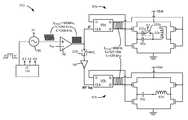
- Two radiatorsare generally present in the IPG 100 : a telemetry radiator 13 used to transmit/receive data to/from an external controller 12 ; and a charging radiator 18 for charging or recharging the IPG's power source or battery 26 using an external charger 50 .
- an external controller 12such as a hand-held programmer or a clinician's programmer, is used to wirelessly send data to and receive data from the IPG 100 .
- the external controller 12can send programming data to the IPG 100 to dictate the therapy the IPG 100 will provide to the patient.
- the external controller 12can act as a receiver of data from the IPG 100 , such as various data reporting on the IPG's status.
- the external controller 12like the IPG 100 , also contains a PCB 70 on which electronic components 72 are placed to control operation of the external controller 12 .
- the communication of data to and from the external controller 12is enabled by a radiator, which may comprise for example an antenna or (as shown) a radiator 17 , which is discussed further below.
- the external charger 50also typically a hand-held device, is used to wirelessly convey power to the IPG 100 , which power can be used to recharge the IPG's battery 26 .
- the transfer of power from the external charger 50is enabled by a radiator which can comprise a radiator 17 ′, which is discussed further below.
- the external charger 50is depicted as having a similar construction to the external controller 12 , but in reality they will differ in accordance with their functionalities as one skilled in the art will appreciate.
- both the IPG 100 and the external devices 12 and 50have radiators which act together as a pair.
- the relevant pair of radiatorscomprises radiator 17 from the controller and radiator 13 from the IPG.
- the relevant pair of radiatorscomprises radiator 17 ′ from the external charger and radiator 18 from the IPG.
- radiator 17When data is to be sent from the external controller 12 to the IPG 100 for example, radiator 17 is energized with an alternating current (AC). Such energizing of the radiator 17 to transfer data can occur using a Frequency Shift Keying (FSK) protocol for example, such as disclosed in U.S. patent application Ser. No. 11/780,369, filed Jul. 19, 2007. Energizing the radiator 17 produces an magnetic field, which in turn induces a current in the IPG's radiator 13 , which current can then be demodulated to recover the original data.
- FSKFrequency Shift Keying
- radiator 17 ′When power is to be transmitted from the external charger 50 to the IPG 100 , radiator 17 ′ is again energized with an alternating current.
- Such energizingis generally of a constant frequency, and may be of a larger magnitude than that used during the transfer of data, but otherwise the physics involved are similar.
- Energy to energize radiators 17 and 17 ′can come from batteries in the external controller 12 and the external charger 50 , respectively, which like the IPG's battery 26 are preferably rechargeable. However, power may also come from plugging the external controller 12 or external charger 50 into a wall outlet plug (not shown), etc.
- inductive transmission of data or powercan occur transcutaneously, i.e., through the patient's tissue 25 , making it particularly useful in a medical implantable device system.
- the radiators 17 and 13 , or 17 ′ and 18preferably lie in planes that are parallel, along collinear axes, and with the radiators in as close as possible to each other. Such an orientation between the radiators 17 and 13 will generally improve the coupling between them, but deviation from ideal orientations can still result in suitably reliable data or power transfer.
- the typical implantable medical device systemrequires two external devices: the external controller 12 and the external charger 50 . Both are needed by a typical patient at one time or another with good frequency.
- the external charger 50is typically needed to recharge the battery 26 in the IPG 100 on a regular basis, as often as every day depending on the stimulation settings.
- the external controller 12can also be needed on a daily basis by the patient to adjust the stimulation therapy as needed at a particular time. Therefore, the patient is encumbered by the need to manipulate two completely independent devices. This means the patient must: learn how to use both devices; carry the bulk of both devices (e.g., when traveling); replace the batteries in both devices and/or recharge them as necessary; pay for both devices, etc. In all, the requirement of two independent external devices is considered inconvenient.
- FIGS. 1A and 1Bshow an implantable pulse generator (IPG), and the manner in which an electrode array is coupled to the IPG in accordance with the prior art.
- IPGimplantable pulse generator
- FIG. 2shows wireless communication of data between an external controller and an IPG, and wireless communication of power from an external charger to the IPG, in accordance with the prior art.
- FIG. 3shows an embodiment of an improved external device containing both data telemetry and charging circuitry within a single housing.
- FIG. 4shows the external device of FIG. 3 communicating both data and power to the IPG.
- FIG. 5shows in the internal structure of the external device of FIG. 3 .
- FIG. 6shows the driving circuitry used to drive the radiator(s) in the external device of FIG. 3 .
- the description that followsrelates to use of the invention within a spinal cord stimulation (SCS) system.
- SCSspinal cord stimulation
- the inventionis not so limited. Rather, the invention may be used with any type of implantable medical device system.
- the present inventionmay be used as part of a system employing an implantable sensor, an implantable pump, a pacemaker, a defibrillator, a cochlear stimulator, a retinal stimulator, a stimulator configured to produce coordinated limb movement, a cortical and deep brain stimulator, or in any other neural stimulator configured to treat any of a variety of conditions.
- an embodiment of an external device for an implantable medical device systemis described herein, where the external device has both circuitry for charging the implantable medical device and circuitry for telemetering data to and from the medical implant contained within a single housing.
- the external devicein one embodiment includes orthogonal radiators in which both the radiators are used for data transfer, and in which at least one of the radiators is used for power transfer. Having charging and data telemetry circuitry fully integrated within a single external device conveniences both patient and clinician.
- FIG. 3illustrates one embodiment of a hand-holdable external device 200 that includes both charging and data telemetry circuitry within the same housing 215 .
- the housing 215encloses other components, such as a battery, a microcontroller, a printed circuit board, radiator(s), etc., which are explained in detail further below.
- the shape of the housingalthough shown to be substantially rectangular, is not limited to the one shown in FIG. 3 .
- the shapemay also be circular, elliptical, etc., and may be designed for easy handling, effective coupling with the IPG 100 , etc.
- the external device 200allows the user to control data telemetry and charging functions through a user interface 202 .
- the user interface 202generally allows the user to telemeter data (such as a new therapy program) from the external device 200 to the IPG 100 , to charge the battery in the IPG 100 , or to monitor various forms of status feedback from the IPG 100 .
- the user interface 202may be similar to a cell phone for example, and includes a display 265 , an enter or select button 270 , and menu navigation buttons 272 .
- Soft keys 278can be used to select various functions, which functions will vary depending on the status of the menu options available at any given time.
- a speakeris also included within the housing 215 to provide audio cues to the user (not shown). Alternatively, a vibration motor can provide feedback for users with hearing impairments.
- the display 265optimally displays both text and graphics to convey necessary information to the patient such as menu options, stimulation settings, IPG battery status, external device battery status, or to indicate if stimulation is on or off, or to indicate the status of charging.
- the display 265may comprise a monochrome liquid crystal display (LCD) using twisted nematic (TN) or super twisted nematic (STN) liquid crystal technology, as described further in U.S. patent application Ser. No. 11/935,111, filed Nov. 5, 2007, which is incorporated herein by reference in its entirety.
- the display 265may also comprise a color display such as a color super twisted nematic (CSTN), a thin-film transistor (TFT) LCD, or an organic light-emitting diode (OLED) display, which again are discussed in the '111 application.
- CSTNcolor super twisted nematic
- TFTthin-film transistor
- OLEDorganic light-emitting diode
- FIG. 4illustrates the external device 200 interacting with the IPG 100 , and shows both two-way data telemetry and one-way power transfer, both of which occur via magnetic coupling as explained earlier.
- two radiators 62 a and 62 bare provided within the external device, and in one embodiment, both radiators are used for telemetry, while only one is used for charging, as explained further below.
- the external device 200interacts with telemetry coil 13 and charging coil 18 in the IPG 100 in the same manner discussed earlier.
- radiators 62 a and 62 bWhether telemetry data or power is transferred to the IPG via radiators 62 a and 62 b depends upon whether the external device 200 is in telemetry mode or power transfer mode.
- the alternating current energizing radiators 62 a and/or 62 bcan be a carrier signal modulated with the data, e.g., using an FSK modulated protocol as described earlier.
- the radiator 62 acan be simply energized with an unmodulated carrier signal.
- the radiators 62 a and 62 bcan also receive telemetry transmitted by the IPG 100 .
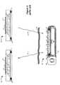
- FIG. 5shows the internal structure of the external device 200 and the physical orientation of the radiators 62 a and 62 b as well as some other components. So that the internal components can be more easily seen, the external device 200 is depicted without its outer housing 215 , and from front, back, and side perspectives.
- the front viewdiscloses a PCB 120 which carries the display 265 and switches 122 comprising user interface 202 .
- Switches 122couple with the bottom surfaces of soft keys 270 - 274 shown in FIG. 3 so that when the user presses any of the soft keys 270 - 274 , the corresponding switch is activated to convey the user response to the circuitry on the PCB 120 .
- the back viewshows the circuitry on the underside of PCB 120 , including the radiators 62 a and 62 b and the battery 126 . Also visible in part are other integrated and discrete components 151 necessary to implement the charging and data transfer functionality of the external device, such as microcontroller 150 .
- radiators 62 a and 62 bare respectively wrapped around axes 54 a and 54 b which are orthogonal. More specifically, radiator 62 b is wrapped in a racetrack, planar configuration around the back of the PCB 120 , while radiator 62 a is wrapped around a ferrite core 128 and affixed to the PCB 120 by epoxy. Axis 54 a is perpendicular to the plane of the radiator 62 a (seen more clearly in the side view), while axis 54 b is parallel to the length of the core on which radiator 62 b is wound. To minimize heating, integrated and discrete components 151 and the battery 126 are placed as far as possible from the electromagnetic fields generated by the radiators.
- components 151 on the PCB 120can be placed at least partially underneath the battery 126 as shown. However, it will be appreciated by a person of skill in the art that different arrangements for components 151 are possible.
- Axes 54 a and 54 bare preferably orthogonal, i.e., the angle between axes 54 a and 54 b is preferably 90 degrees. However, this is not strictly necessary, and any non-zero angle can be used as well. That being said, maximal benefit is achieved when this angle approaches 90 degrees, i.e., approximately 90 as close as mechanical tolerances will allow.
- radiators 62 a and 62 bare used for data telemetry
- these radiatorscan carry alternating currents that are substantially 90 degrees out of phase with each other, as described in U.S. patent application Ser. No. 11/853,624, filed Sep. 11, 2007, which is incorporated herein by reference in its entirety. This produces a magnetic field which rotates, and reduces nulls in the coupling between the external device 200 and the receiving telemetry radiator 13 within the IPG 100 .
- the dual radiators 62 a and 62 bcan likewise be used to receive telemetry from the IPG 100 .
- FIG. 6depicts driver circuitry 210 used to drive the two radiators 62 a and 62 b to telemeter data and power to the IPG 100 . Operation of the driver circuitry 210 relevant to the transfer of data is discussed first.
- the two radiators 62 a and 62 bstarts with the external device's microcontroller 150 , preferably Part No. MSP430 manufactured by Texas Instruments, Inc., which outputs a string of digital data bits that are ultimately to be wirelessly broadcast to the IPG. These bits are sent to frequency modulation circuitry (modulator) 90 where they are modulated onto a carrier signal.
- the modulator 90can comprise a Direct Digital Synthesizer such as part number AD9834 manufactured by Analog Devices, Inc.
- the carrier signal provided by the modulator 90can comprise nominally either 250 kHz in the event of data telemetry, or 160 kHz in the event of charging, and is selected by signal K 1 as output from the microcontroller 150 .
- K 1could comprise more complex multi-signal bus structures.
- This AC output from the modulator 90is then turned into a square wave of the same frequency by a comparator or limiter 92 as one skilled in the art will appreciate. As will be seen, later in the driver circuitry 210 these frequencies will be halved to their actual broadcasted values.
- output K 2 of the microcontroller 150closes switch 208 , which allows the modulated data to flow to both driver leg 82 a which drives radiator 62 a , and driver leg 82 b which drives radiator 62 b .
- Each legreceives the square wave output from limiter 92 at a clocking input (CLK) of D flip flops 96 a and 96 b , although the data received at the leg 82 b is inverted by an inverter 94 .
- the inverteressentially works a 180 degree shift in the square wave data signal.
- the complimentary output Q′ of each flip flop 96 a and 96 bis coupled to the corresponding input D.
- the outputs (Q/Q′) of the flip flops 96 a and 96 bi.e., the drive signals 83 a and 83 b
- the drive signals 83 a and 83 bare in turn used to resonate the radiators 62 a and 62 b , again, with drive signal 83 b arriving at radiator 62 b with a 90 degree lag. (This phase difference need not be exactly 90 degrees). Resonance is achieved for each radiator 62 a and 62 b through a serial connection to a tuning capacitor 98 a or 98 b , respectively, which results in resonant LC circuits, or “tank” circuits.
- output K 3 from the microcontroller 150is used to open switch 202 a , which removes additional capacitor 200 a from the tank circuit in leg 82 a , thus tuning that tank circuit to resonate roughly at 125 kHz, i.e., suitable for telemetry of the 121 kHz and 129 kHz signals.
- the N-channel (NCH) and P-channel (PCH) transistorsare gated by the drive signals 83 a and 83 b to apply the voltage, Vbat, needed to energize the radiators 62 a and 62 b .
- Vbatcomes from the battery 126 within the external device 200 ( FIG. 5 ).
- the external device 200would additionally contain receiver circuitry. However, because exemplary receiver circuitry is disclosed in the above-incorporated '624 application, such details are not repeated here.
- the microcontroller 150changes the status of control signals K 1 , K 2 , and K 3 sent to the driving circuitry 210 .
- control signals K 2 and K 3respectively open and close their associated switches 208 and 202 a . Opening switch 208 effectively decouples the lower leg 82 b of the driver circuit 210 , such that only the upper leg 82 a , and its planar radiator 62 a ( FIG. 5 ), will be used to produce a charging field.
- radiator 62 bis not used during charging.
- switch 208could be closed, and similar to operation during telemetry, the produced charging field would rotate due to the 90-degree phase difference.
- the resonant frequency of the tank circuit in the upper leg 82 ais tuned from 125 kHz to 80 kHz. This occurs via control signal K 3 , which during charging acts to close switch 202 a , thus adding capacitor 200 a to the tank circuit so as to lower its resonant frequency.
- the value of the capacitor 200 ais selected such that the parallel combination of the capacitors 200 a and 98 a , in conjunction with the inductance provided by radiator 62 a , result in an LC circuit with a resonating frequency substantially equal to 80 kHz. So tuned, the radiator 62 a in the external device 200 produces an unmodulated magnetic charging field of 80 kHz, which is received by the charging coil 18 in the IPG ( FIG. 4 ).
- the frequency used for charging, f chargecan be the same as the center frequency used for transmitting data, i.e., f c .
- f cthe center frequency used for transmitting data
- the strength of the magnetic fields produced by the driving circuitry 210 during telemetry and chargingand be made adjustable, and can be different between these two modes. Because the alternating current in the tank circuit(s) will be at maximum levels when the frequency of the drive signal 83 a and 83 b is equal to the tank circuits' resonant frequency, the frequency of the drive signal can be increased or decrease from this optimal value to decrease the current in the tank, and hence the produced field strength. Such trimming of the drive frequency can occur via signal(s) K 1 or other signals used to tune the modulator 90 . Such control can also be part of a feedback control loop which may include feedback from the IPG 100 to achieve optimal power and data transfer to the receiver circuits in IPG 100 .
- Radiators 62 a and 62 bcan be made similarly.
- the radiators 62 a and 62 bmay differ in their composition based on their predominant mode of operation.
- radiator 62 bis used only to transfer data during data telemetry mode, while radiator 62 a is used for both power and data transmission. Continuous operation of a radiator carrying AC current can result in undesirable heating of the radiator. Therefore, radiator 62 a can be designed with specifications that result in minimizing heating.
- radiator 62 acan be an air core radiator where the winding is made of a low resistance material, e.g., litz-wire. Because radiator 62 b is used only intermittently for data transfer, it may not experience excessive heating, and can be made of a ferrite rod core and solid copper conductors instead.
- Additional measures to minimize heating of the external device 200can include minimizing eddy currents.
- the PCB 120on which the radiators are mounted, may be designed with ground and power traces instead of ground and power planes so as to reduce eddy currents in the PCB. Removal or minimizing of the components 151 from within the radiator 62 a (see FIG. 5 ) is also helpful in this regard. (In actual practice, some components 151 may need to be placed inside the coil area if there is insufficient room outside this area.) Furthermore, active cooling in the form of fans and closed loop temperature control systems can also be employed in the external device 200 .
Landscapes
- Health & Medical Sciences (AREA)
- Physics & Mathematics (AREA)
- Radiology & Medical Imaging (AREA)
- Engineering & Computer Science (AREA)
- Biomedical Technology (AREA)
- Nuclear Medicine, Radiotherapy & Molecular Imaging (AREA)
- Acoustics & Sound (AREA)
- Life Sciences & Earth Sciences (AREA)
- Animal Behavior & Ethology (AREA)
- General Health & Medical Sciences (AREA)
- Public Health (AREA)
- Veterinary Medicine (AREA)
- Electromagnetism (AREA)
- Electrotherapy Devices (AREA)
- Charge And Discharge Circuits For Batteries Or The Like (AREA)
Abstract
Description
The present invention relates to data telemetry and power transfer in an implantable medical device system.
Implantable stimulation devices are devices that generate and deliver electrical stimuli to body nerves and tissues for the therapy of various biological disorders, such as pacemakers to treat cardiac arrhythmia, defibrillators to treat cardiac fibrillation, cochlear stimulators to treat deafness, retinal stimulators to treat blindness, muscle stimulators to produce coordinated limb movement, spinal cord stimulators to treat chronic pain, cortical and deep brain stimulators to treat motor and psychological disorders, and other neural stimulators to treat urinary incontinence, sleep apnea, shoulder sublaxation, etc. The present invention may find applicability in all such applications, although the description that follows will generally focus on the use of the invention within a Spinal Cord Stimulation (SCS) system, such as that disclosed in U.S. Pat. No. 6,516,227.
Spinal cord stimulation is a well-accepted clinical method for reducing pain in certain populations of patients. As shown inFIGS. 1A and 1B , a SCS system typically includes an Implantable Pulse Generator (IPG)100, which includes abiocompatible case 30 formed of titanium for example. Thecase 30 typically holds the circuitry and power source or battery necessary for the IPG to function, although IPGs can also be powered via external RF energy and without a battery. The IPG100 is coupled toelectrodes 106 via one or more electrode leads (twosuch leads electrodes 106 form anelectrode array 110. Theelectrodes 106 are carried on aflexible body 108, which also houses theindividual signal wires lead 102, labeled E1-E8, and eight electrodes onlead 104, labeled E9-E16, although the number of leads and electrodes is application specific and therefore can vary.
As shown inFIG. 2 , the IPG100 typically includes an electronic substrate assembly14 including a printed circuit board (PCB)16, along with various electronic components20, such as microprocessors, integrated circuits, and capacitors mounted to the PCB16. Two radiators are generally present in the IPG100: atelemetry radiator 13 used to transmit/receive data to/from anexternal controller 12; and acharging radiator 18 for charging or recharging the IPG's power source orbattery 26 using anexternal charger 50.
As just noted, anexternal controller 12, such as a hand-held programmer or a clinician's programmer, is used to wirelessly send data to and receive data from the IPG100. For example, theexternal controller 12 can send programming data to the IPG100 to dictate the therapy the IPG100 will provide to the patient. Also, theexternal controller 12 can act as a receiver of data from the IPG100, such as various data reporting on the IPG's status. Theexternal controller 12, like the IPG100, also contains aPCB 70 on whichelectronic components 72 are placed to control operation of theexternal controller 12. Auser interface 74 similar to that used for a computer, cell phone, or other hand held electronic device, and including touchable buttons and a display for example, allows a patient or clinician to operate theexternal controller 12. The communication of data to and from theexternal controller 12 is enabled by a radiator, which may comprise for example an antenna or (as shown) aradiator 17, which is discussed further below.
Theexternal charger 50, also typically a hand-held device, is used to wirelessly convey power to the IPG100, which power can be used to recharge the IPG'sbattery 26. The transfer of power from theexternal charger 50 is enabled by a radiator which can comprise aradiator 17′, which is discussed further below. For the purpose of the basic explanation here, theexternal charger 50 is depicted as having a similar construction to theexternal controller 12, but in reality they will differ in accordance with their functionalities as one skilled in the art will appreciate.
Wireless data telemetry and power transfer between theexternal devices external devices external controller 12, the relevant pair of radiators comprisesradiator 17 from the controller andradiator 13 from the IPG. While in case of theexternal charger 50, the relevant pair of radiators comprisesradiator 17′ from the external charger andradiator 18 from the IPG.
When data is to be sent from theexternal controller 12 to the IPG100 for example,radiator 17 is energized with an alternating current (AC). Such energizing of theradiator 17 to transfer data can occur using a Frequency Shift Keying (FSK) protocol for example, such as disclosed in U.S. patent application Ser. No. 11/780,369, filed Jul. 19, 2007. Energizing theradiator 17 produces an magnetic field, which in turn induces a current in the IPG'sradiator 13, which current can then be demodulated to recover the original data.
When power is to be transmitted from theexternal charger 50 to the IPG100,radiator 17′ is again energized with an alternating current. Such energizing is generally of a constant frequency, and may be of a larger magnitude than that used during the transfer of data, but otherwise the physics involved are similar.
Energy to energizeradiators external controller 12 and theexternal charger 50, respectively, which like the IPG'sbattery 26 are preferably rechargeable. However, power may also come from plugging theexternal controller 12 orexternal charger 50 into a wall outlet plug (not shown), etc.
As is well known, inductive transmission of data or power can occur transcutaneously, i.e., through the patient'stissue 25, making it particularly useful in a medical implantable device system. During the transmission of data or power, theradiators radiators
The Inventors consider it unfortunate that the typical implantable medical device system requires two external devices: theexternal controller 12 and theexternal charger 50. Both are needed by a typical patient at one time or another with good frequency. Theexternal charger 50 is typically needed to recharge thebattery 26 in the IPG100 on a regular basis, as often as every day depending on the stimulation settings. Theexternal controller 12 can also be needed on a daily basis by the patient to adjust the stimulation therapy as needed at a particular time. Therefore, the patient is encumbered by the need to manipulate two completely independent devices. This means the patient must: learn how to use both devices; carry the bulk of both devices (e.g., when traveling); replace the batteries in both devices and/or recharge them as necessary; pay for both devices, etc. In all, the requirement of two independent external devices is considered inconvenient.
This disclosure provides embodiments of solutions to mitigate these problems.
The description that follows relates to use of the invention within a spinal cord stimulation (SCS) system. However, the invention is not so limited. Rather, the invention may be used with any type of implantable medical device system. For example, the present invention may be used as part of a system employing an implantable sensor, an implantable pump, a pacemaker, a defibrillator, a cochlear stimulator, a retinal stimulator, a stimulator configured to produce coordinated limb movement, a cortical and deep brain stimulator, or in any other neural stimulator configured to treat any of a variety of conditions.
An embodiment of an external device for an implantable medical device system is described herein, where the external device has both circuitry for charging the implantable medical device and circuitry for telemetering data to and from the medical implant contained within a single housing. The external device in one embodiment includes orthogonal radiators in which both the radiators are used for data transfer, and in which at least one of the radiators is used for power transfer. Having charging and data telemetry circuitry fully integrated within a single external device conveniences both patient and clinician.
Theexternal device 200 allows the user to control data telemetry and charging functions through auser interface 202. Theuser interface 202 generally allows the user to telemeter data (such as a new therapy program) from theexternal device 200 to theIPG 100, to charge the battery in theIPG 100, or to monitor various forms of status feedback from theIPG 100. Theuser interface 202 may be similar to a cell phone for example, and includes adisplay 265, an enter orselect button 270, andmenu navigation buttons 272.Soft keys 278 can be used to select various functions, which functions will vary depending on the status of the menu options available at any given time. A speaker is also included within thehousing 215 to provide audio cues to the user (not shown). Alternatively, a vibration motor can provide feedback for users with hearing impairments.
Thedisplay 265 optimally displays both text and graphics to convey necessary information to the patient such as menu options, stimulation settings, IPG battery status, external device battery status, or to indicate if stimulation is on or off, or to indicate the status of charging. Thedisplay 265 may comprise a monochrome liquid crystal display (LCD) using twisted nematic (TN) or super twisted nematic (STN) liquid crystal technology, as described further in U.S. patent application Ser. No. 11/935,111, filed Nov. 5, 2007, which is incorporated herein by reference in its entirety. Thedisplay 265 may also comprise a color display such as a color super twisted nematic (CSTN), a thin-film transistor (TFT) LCD, or an organic light-emitting diode (OLED) display, which again are discussed in the '111 application.
Whether telemetry data or power is transferred to the IPG viaradiators external device 200 is in telemetry mode or power transfer mode. In telemetry mode, the alternating current energizingradiators 62aand/or62bcan be a carrier signal modulated with the data, e.g., using an FSK modulated protocol as described earlier. In power transfer mode, theradiator 62acan be simply energized with an unmodulated carrier signal. Theradiators IPG 100.
The front view discloses aPCB 120 which carries thedisplay 265 andswitches 122 comprisinguser interface 202.Switches 122 couple with the bottom surfaces of soft keys270-274 shown inFIG. 3 so that when the user presses any of the soft keys270-274, the corresponding switch is activated to convey the user response to the circuitry on thePCB 120.
The back view shows the circuitry on the underside ofPCB 120, including theradiators battery 126. Also visible in part are other integrated anddiscrete components 151 necessary to implement the charging and data transfer functionality of the external device, such asmicrocontroller 150.
As seen in the back and side views, the tworadiators radiator 62bis wrapped in a racetrack, planar configuration around the back of thePCB 120, whileradiator 62ais wrapped around a ferrite core128 and affixed to thePCB 120 by epoxy.Axis 54ais perpendicular to the plane of theradiator 62a(seen more clearly in the side view), whileaxis 54bis parallel to the length of the core on whichradiator 62bis wound. To minimize heating, integrated anddiscrete components 151 and thebattery 126 are placed as far as possible from the electromagnetic fields generated by the radiators. For example, note that none of the integrated anddiscrete components 151 come within the boundary ofradiator 62a. Additionally, if necessary for density purposes,components 151 on thePCB 120 can be placed at least partially underneath thebattery 126 as shown. However, it will be appreciated by a person of skill in the art that different arrangements forcomponents 151 are possible.
In embodiments in which bothradiators external device 200 and the receivingtelemetry radiator 13 within theIPG 100. Thedual radiators IPG 100.
Generation of the drive signals for83aand83bthe tworadiators microcontroller 150, preferably Part No. MSP430 manufactured by Texas Instruments, Inc., which outputs a string of digital data bits that are ultimately to be wirelessly broadcast to the IPG. These bits are sent to frequency modulation circuitry (modulator)90 where they are modulated onto a carrier signal. Themodulator 90 can comprise a Direct Digital Synthesizer such as part number AD9834 manufactured by Analog Devices, Inc. The carrier signal provided by themodulator 90 can comprise nominally either 250 kHz in the event of data telemetry, or 160 kHz in the event of charging, and is selected by signal K1 as output from themicrocontroller 150. Signal K1 can be a single binary signal which for example could control themodulator 90 to produce the frequency suitable for data telemetry (e.g., K1=‘1’) or charging (e.g., K1=‘0’). Alternatively, K1 could comprise more complex multi-signal bus structures.
In the event of data telemetry, the digital data bits modulate the carrier around its center frequency of fc=250 kHz, such that a logic ‘0’ produces a frequency, f0′=242 kHz, and a logic ‘1’ produces a frequency, f1′=258 kHz. This AC output from themodulator 90 is then turned into a square wave of the same frequency by a comparator orlimiter 92 as one skilled in the art will appreciate. As will be seen, later in thedriver circuitry 210 these frequencies will be halved to their actual broadcasted values.
During data telemetry, output K2 of themicrocontroller 150 closes switch208, which allows the modulated data to flow to bothdriver leg 82awhich drivesradiator 62a, anddriver leg 82bwhich drivesradiator 62b. Each leg receives the square wave output fromlimiter 92 at a clocking input (CLK) ofD flip flops leg 82bis inverted by aninverter 94. The inverter essentially works a 180 degree shift in the square wave data signal. The complimentary output Q′ of eachflip flop flip flops flip flops inverter 94 at the higher frequency (fc′=250 kHz) signal.
The drive signals83aand83bare in turn used to resonate theradiators radiator 62bwith a 90 degree lag. (This phase difference need not be exactly 90 degrees). Resonance is achieved for eachradiator tuning capacitor microcontroller 150 is used to openswitch 202a, which removesadditional capacitor 200afrom the tank circuit inleg 82a, thus tuning that tank circuit to resonate roughly at 125 kHz, i.e., suitable for telemetry of the 121 kHz and 129 kHz signals. As one skilled in the art will appreciate, the N-channel (NCH) and P-channel (PCH) transistors are gated by the drive signals83aand83bto apply the voltage, Vbat, needed to energize theradiators battery 126 within the external device200 (FIG. 5 ). One skilled in the art will appreciate that the disclosed arrangement reverses the polarity of this battery voltage Vbat across the tank circuit (+Vbat followed by −Vbat followed by +Vbat, etc.), which in turn causes the radiators to resonate and therefore broadcast at the frequencies of interest (f0=125 kHz; f1=129 kHz). As noted earlier, such broadcast is received attelemetry radiator 13 in the IPG100 (FIG. 4 ).
If tworadiators IPG 100, theexternal device 200 would additionally contain receiver circuitry. However, because exemplary receiver circuitry is disclosed in the above-incorporated '624 application, such details are not repeated here.
When theexternal device 200 operates in a charging mode to produce a magnetic field for charging thebattery 26 in theIPG 100, themicrocontroller 150 changes the status of control signals K1, K2, and K3 sent to the drivingcircuitry 210. K1 in this mode now indicates to themodulator 90 to output an unmodulated lower frequency more suitable for charging, i.e., fcharge′=160 kHz. As with the data telemetry mode, this frequency is eventually halved via operation of the flip flop(s) to fcharge=80 kHz.
Additionally, when charging, control signals K2 and K3 respectively open and close their associatedswitches Opening switch 208 effectively decouples thelower leg 82bof thedriver circuit 210, such that only theupper leg 82a, and itsplanar radiator 62a(FIG. 5 ), will be used to produce a charging field. In other words, in this embodiment,radiator 62bis not used during charging. However, it should be noted that this is not strictly necessary, and insteadradiator 62bcould be energized during charging. In such a case, switch208 could be closed, and similar to operation during telemetry, the produced charging field would rotate due to the 90-degree phase difference. In any event, at least one drive signal83aor83bwith frequency fcharge=80 kHz is presented to at least one of the tank circuits.
To accommodate this lower drive frequency from 125 kHz (data telemetry) to 80 kHz (charging), the resonant frequency of the tank circuit in theupper leg 82ais tuned from 125 kHz to 80 kHz. This occurs via control signal K3, which during charging acts to closeswitch 202a, thus addingcapacitor 200ato the tank circuit so as to lower its resonant frequency. Note that the value of thecapacitor 200ais selected such that the parallel combination of thecapacitors radiator 62a, result in an LC circuit with a resonating frequency substantially equal to 80 kHz. So tuned, theradiator 62ain theexternal device 200 produces an unmodulated magnetic charging field of 80 kHz, which is received by the chargingcoil 18 in the IPG (FIG. 4 ).
In an alternative embodiment, the frequency used for charging, fcharge, can be the same as the center frequency used for transmitting data, i.e., fc. In such a case, it would not be necessary to tune the tank circuitry when transitioning between the telemetry and charging modes, and switch202aandcapacitor 200acould be dispensed with.
The strength of the magnetic fields produced by the drivingcircuitry 210 during telemetry and charging and be made adjustable, and can be different between these two modes. Because the alternating current in the tank circuit(s) will be at maximum levels when the frequency of the drive signal83aand83bis equal to the tank circuits' resonant frequency, the frequency of the drive signal can be increased or decrease from this optimal value to decrease the current in the tank, and hence the produced field strength. Such trimming of the drive frequency can occur via signal(s) K1 or other signals used to tune themodulator 90. Such control can also be part of a feedback control loop which may include feedback from theIPG 100 to achieve optimal power and data transfer to the receiver circuits inIPG 100.
Additional measures to minimize heating of theexternal device 200 can include minimizing eddy currents. For example, thePCB 120, on which the radiators are mounted, may be designed with ground and power traces instead of ground and power planes so as to reduce eddy currents in the PCB. Removal or minimizing of thecomponents 151 from within theradiator 62a(seeFIG. 5 ) is also helpful in this regard. (In actual practice, somecomponents 151 may need to be placed inside the coil area if there is insufficient room outside this area.) Furthermore, active cooling in the form of fans and closed loop temperature control systems can also be employed in theexternal device 200.
Although particular embodiments of the present invention have been shown and described, it should be understood that the above discussion is not intended to limit the present invention to these embodiments. It will be obvious to those skilled in the art that various changes and modifications may be made without departing from the spirit and scope of the present invention. Thus, the present invention is intended to cover alternatives, modifications, and equivalents that may fall within the spirit and scope of the present invention as defined by the claims.
Claims (8)
1. An external device for use with an implantable medical device, comprising:
a hand-holdable housing comprising a display and user interface for controlling telemetry and charging;
driver circuitry within the housing for driving at least one radiator within the housing, wherein the driver circuitry is adjustable either to a first frequency range or to a second frequency outside the first frequency range; and
a first and second radiator, wherein the driver circuitry is configured to drive the first and second radiators in the first frequency range for telemetering data to the implantable medical device, and wherein the driver circuitry is configured to drive only the second radiator at the second frequency for providing power to the implantable medical device.
2. The device ofclaim 1 , wherein the data is telemetered at a first frequency within the first frequency range, and wherein the power is provided at the second frequency.
3. The device ofclaim 2 , wherein the second frequency is lower than the first frequency.
4. The device ofclaim 2 , wherein the first frequency is modulated, but the second frequency is unmodulated.
5. The device ofclaim 1 , wherein the driving circuitry comprises a modulator, wherein the frequency of the modulator is adjustable between the first frequency range and the second frequency.
6. The device ofclaim 1 , wherein the second radiator comprises a resonator circuit with a resonant frequency.
7. The device ofclaim 6 , wherein the resonant frequency of the resonator circuit is adjustable between frequencies in the first frequency range and the second frequency.
8. The device ofclaim 6 , wherein the resonator circuit comprises an LC tank circuit.
Priority Applications (8)
| Application Number | Priority Date | Filing Date | Title |
|---|---|---|---|
| US12/368,385US8335569B2 (en) | 2009-02-10 | 2009-02-10 | External device for communicating with an implantable medical device having data telemetry and charging integrated in a single housing |
| JP2011549139AJP5297538B2 (en) | 2009-02-10 | 2009-10-09 | External device for communicating with an implantable medical device with data telemetry and charger integrated in a single housing |
| EP09744513AEP2403594A1 (en) | 2009-02-10 | 2009-10-09 | External device for communicating with an implantable medical device having data telemetry and charging integrated in a single housing |
| AU2009340061AAU2009340061B2 (en) | 2009-02-10 | 2009-10-09 | External device for communicating with an implantable medical device having data telemetry and charging integrated in a single housing |
| PCT/US2009/060204WO2010093384A1 (en) | 2009-02-10 | 2009-10-09 | External device for communicating with an implantable medical device having data telemetry and charging integrated in a single housing |
| CA2748898ACA2748898C (en) | 2009-02-10 | 2009-10-09 | External device for communicating with an implantable medical device having data telemetry and charging integrated in a single housing |
| US13/676,571US9020602B2 (en) | 2009-02-10 | 2012-11-14 | External device for communicating with an implantable medical device having data telemetry and charging integrated in a single housing |
| JP2013125608AJP5734351B2 (en) | 2009-02-10 | 2013-06-14 | External device for communicating with an implantable medical device with data telemetry and charger integrated in a single housing |
Applications Claiming Priority (1)
| Application Number | Priority Date | Filing Date | Title |
|---|---|---|---|
| US12/368,385US8335569B2 (en) | 2009-02-10 | 2009-02-10 | External device for communicating with an implantable medical device having data telemetry and charging integrated in a single housing |
Related Child Applications (1)
| Application Number | Title | Priority Date | Filing Date |
|---|---|---|---|
| US13/676,571ContinuationUS9020602B2 (en) | 2009-02-10 | 2012-11-14 | External device for communicating with an implantable medical device having data telemetry and charging integrated in a single housing |
Publications (2)
| Publication Number | Publication Date |
|---|---|
| US20100204756A1 US20100204756A1 (en) | 2010-08-12 |
| US8335569B2true US8335569B2 (en) | 2012-12-18 |
Family
ID=41611199
Family Applications (2)
| Application Number | Title | Priority Date | Filing Date |
|---|---|---|---|
| US12/368,385Expired - Fee RelatedUS8335569B2 (en) | 2009-02-10 | 2009-02-10 | External device for communicating with an implantable medical device having data telemetry and charging integrated in a single housing |
| US13/676,571Expired - Fee RelatedUS9020602B2 (en) | 2009-02-10 | 2012-11-14 | External device for communicating with an implantable medical device having data telemetry and charging integrated in a single housing |
Family Applications After (1)
| Application Number | Title | Priority Date | Filing Date |
|---|---|---|---|
| US13/676,571Expired - Fee RelatedUS9020602B2 (en) | 2009-02-10 | 2012-11-14 | External device for communicating with an implantable medical device having data telemetry and charging integrated in a single housing |
Country Status (6)
| Country | Link |
|---|---|
| US (2) | US8335569B2 (en) |
| EP (1) | EP2403594A1 (en) |
| JP (2) | JP5297538B2 (en) |
| AU (1) | AU2009340061B2 (en) |
| CA (1) | CA2748898C (en) |
| WO (1) | WO2010093384A1 (en) |
Cited By (48)
| Publication number | Priority date | Publication date | Assignee | Title |
|---|---|---|---|---|
| US20130073005A1 (en)* | 2009-02-10 | 2013-03-21 | Boston Scientific Neuromodulation Corporation | External Device for Communicating with an Implantable Medical Device Having Data Telemetry and Charging Integrated in a Single Housing |
| US8644949B2 (en) | 2010-01-19 | 2014-02-04 | Boston Scientific Neuromodulation Corporation | Pressure-sensitive external charger for an implantable medical device |
| US8694117B2 (en) | 2009-07-06 | 2014-04-08 | Boston Scientific Neuromodulation Corporation | External charger for a medical implantable device using field sensing coils to improve coupling |
| US8812129B2 (en) | 2009-07-06 | 2014-08-19 | Boston Scientific Neuromodulation Corporation | External device for an implantable medical system having accessible contraindication information |
| US8895315B2 (en) | 2013-03-12 | 2014-11-25 | Roche Diagnostics Operations, Inc. | Displaying status of a blood glucose measure being transferred wirelessly from a handheld glucose meter |
| US9155898B2 (en) | 2000-03-17 | 2015-10-13 | Boston Scientific Neuromodulation Corporation | Implantable medical device with multi-function single coil |
| US9248279B2 (en) | 2013-07-02 | 2016-02-02 | Greatbatch Ltd. | Neurostimulator configured to sense evoked potentials in peripheral nerves |
| US9272156B2 (en) | 2009-11-11 | 2016-03-01 | Boston Scientific Neuromodulation Corporation | External controller/charger system for an implantable medical device capable of automatically providing data telemetry through a charging coil during a charging session |
| WO2016069090A1 (en) | 2014-10-30 | 2016-05-06 | Boston Scientific Neuromodulation Corporation | External controller for an implantable medical device system with an external charging coil powered by an external battery |
| US9339660B2 (en) | 2013-10-04 | 2016-05-17 | Boston Scientific Neuromodulation Corporation | Implantable medical device with one or more magnetic field sensors to assist with external charger alignment |
| US20160279427A1 (en)* | 2009-10-08 | 2016-09-29 | Boston Scientific Neuromodulation Corporation | Efficient External Charger for an Implantable Medical Device Optimized for Fast Charging and Constrained by an Implant Power Dissipation Limit |
| WO2016164103A1 (en) | 2015-04-08 | 2016-10-13 | Boston Scientific Neuromodulation Corporation | Charging coil holding device for an implantable medical device coupleable to a controller/charger device |
| WO2016204850A1 (en)* | 2015-06-19 | 2016-12-22 | Boston Scientific Neuromodulation Corporation | External powering of implantable medical device dependent on energy of provided therapy |
| US9526906B2 (en) | 2012-07-26 | 2016-12-27 | Nyxoah SA | External resonance matching between an implanted device and an external device |
| US9533162B2 (en) | 2014-08-21 | 2017-01-03 | Boston Scientific Neuromodulation Corporation | Use of a dedicated remote control as an intermediary device to communicate with an implantable medical device |
| US9707402B2 (en) | 2014-02-14 | 2017-07-18 | Boston Scientific Neuromodulation Corporation | Plug-in accessory for configuring a mobile device into an external controller for an implantable medical device |
| WO2017176474A1 (en) | 2016-04-04 | 2017-10-12 | Boston Scientific Neuromodulation Corporation | System to estimate the location of a spinal cord physiological midline |
| WO2017176475A1 (en) | 2016-04-04 | 2017-10-12 | Boston Scientific Neuromodulation Corporation | System to estimate the location of a spinal cord physiological midline |
| WO2018160329A1 (en) | 2017-02-28 | 2018-09-07 | Boston Scientific Neuromodulation Corporation | Implantable medical device with a silicone housing |
| WO2018175005A1 (en) | 2017-03-21 | 2018-09-27 | Boston Scientific Neuromodulation Corporation | External charger with three-axis magnetic field sensor to determine implantable medical device position |
| US10105545B2 (en) | 2015-03-12 | 2018-10-23 | Boston Scientific Neuromodulation Corporation | Assembly with a coaxial audio connector for charging an implantable medical device |
| WO2018200081A1 (en) | 2017-04-24 | 2018-11-01 | Boston Scientific Neuromodulation Corporation | Technique to ensure security for connected implantable medical devices |
| US10226637B2 (en) | 2016-06-15 | 2019-03-12 | Boston Scientific Neuromodulation Corporation | External charger for an implantable medical device having alignment and centering capabilities |
| US20190190296A1 (en)* | 2017-12-15 | 2019-06-20 | Medtronic, Inc. | Medical device temperature estimation |
| US10342984B2 (en) | 2016-06-15 | 2019-07-09 | Boston Scientific Neuromodulation Corporation | Split coil for uniform magnetic field generation from an external charger for an implantable medical device |
| US10363426B2 (en) | 2016-06-15 | 2019-07-30 | Boston Scientific Neuromodulation Corporation | External charger for an implantable medical device for determining position using phase angle or a plurality of parameters as determined from at least one sense coil |
| US10406368B2 (en) | 2016-04-19 | 2019-09-10 | Boston Scientific Neuromodulation Corporation | Pulse generator system for promoting desynchronized firing of recruited neural populations |
| US10420950B2 (en) | 2015-11-29 | 2019-09-24 | Boston Scientific Neuromodulation Corporation | Implantable pulse generator usable during a trial stimulation phase and externally powered by magnetic inductive coupling |
| WO2019231794A1 (en) | 2018-06-01 | 2019-12-05 | Boston Scientific Neuromodulation Corporation | Interleaving stimulation patterns provided by an implantable pulse generator |
| US10576292B2 (en) | 2015-11-29 | 2020-03-03 | Boston Scientific Neuromodulation Corporation | Skull-mounted deep brain stimulator |
| US10603501B2 (en) | 2016-06-15 | 2020-03-31 | Boston Scientific Neuromodulation Corporation | External charger for an implantable medical device having at least one sense coil concentric with a charging coil for determining position |
| US10842989B2 (en) | 2017-11-08 | 2020-11-24 | Boston Scientific Neuromodulation Corporation | System to improve a spinal cord stimulation model based on a physiological midline location |
| US10994146B2 (en) | 2017-12-12 | 2021-05-04 | Boston Scientific Neuromodulation Corporation | External device with electromagnet for use with an implantable medical device |
| US11040209B2 (en) | 2017-01-19 | 2021-06-22 | Boston Scienitific Neuromodulation Corporation | Radio frequency antenna capacitively coupled to a charging coil in an implantable medical device |
| US11116975B2 (en) | 2015-11-09 | 2021-09-14 | Bluewind Medical Ltd. | Optimization of application of current |
| US11129996B2 (en) | 2016-06-15 | 2021-09-28 | Boston Scientific Neuromodulation Corporation | External charger for an implantable medical device for determining position and optimizing power transmission using resonant frequency as determined from at least one sense coil |
| US11173308B2 (en) | 2018-03-05 | 2021-11-16 | Boston Scientific Neuromodulation Corporation | Virtual target pole adjustment based on nerve root trajectory |
| US11213685B2 (en) | 2017-06-13 | 2022-01-04 | Bluewind Medical Ltd. | Antenna configuration |
| US11273313B2 (en) | 2019-04-18 | 2022-03-15 | Boston Scientific Neuromodulation Corporation | Dynamic visualization of neuronal sub population interactions |
| US11278719B2 (en) | 2012-12-06 | 2022-03-22 | Bluewind Medical Ltd. | Delivery of implantable neurostimulators |
| US20220203103A1 (en)* | 2020-12-28 | 2022-06-30 | Advanced Neuromodulation Systems Inc. | System and method for alignment of a wireless charger to an implantable medical device |
| US11400299B1 (en) | 2021-09-14 | 2022-08-02 | Rainbow Medical Ltd. | Flexible antenna for stimulator |
| US11439833B2 (en) | 2016-11-23 | 2022-09-13 | Bluewind Medical Ltd. | Implant-delivery tool |
| US11471692B2 (en) | 2016-06-15 | 2022-10-18 | Boston Scientific Neuromodulation Corporation | External charger for an implantable medical device for adjusting charging power based on determined position using at least one sense coil |
| US11559355B2 (en) | 2018-07-30 | 2023-01-24 | Boston Scientific Neuromodulation Corporation | Augmented and virtual reality for use with neuromodulation therapy |
| US11648410B2 (en) | 2012-01-26 | 2023-05-16 | Bluewind Medical Ltd. | Wireless neurostimulators |
| US11705763B2 (en) | 2021-02-24 | 2023-07-18 | Medtronic, Inc. | Implant location detection and adaptive temperature control |
| US11752355B2 (en) | 2020-10-30 | 2023-09-12 | Medtronic, Inc. | Estimating the temperature of a housing of a device |
Families Citing this family (39)
| Publication number | Priority date | Publication date | Assignee | Title |
|---|---|---|---|---|
| EP2349079B1 (en)* | 2008-10-10 | 2023-06-07 | Implantica Patent Ltd. | Charger for implant |
| US8321029B2 (en) | 2009-09-18 | 2012-11-27 | Boston Scientific Neuromodulation Corporation | External charger usable with an implantable medical device having a programmable or time-varying temperature set point |
| US8311638B2 (en) | 2009-10-15 | 2012-11-13 | Boston Scientific Neuromodulation Corporation | External charger for a medical implantable device using field inducing coils to improve coupling |
| US9042995B2 (en)* | 2010-02-03 | 2015-05-26 | Medtronic, Inc. | Implantable medical devices and systems having power management for recharge sessions |
| WO2011097289A1 (en) | 2010-02-03 | 2011-08-11 | Medtronic, Inc. | Implantable medical devices and systems having dual frequency inductive telemetry and recharge |
| US8674550B2 (en) | 2010-03-25 | 2014-03-18 | General Electric Company | Contactless power transfer system and method |
| US9030159B2 (en) | 2010-03-26 | 2015-05-12 | Boston Scientific Neuromodulation Corporation | Inductive charger with magnetic shielding |
| US8594806B2 (en) | 2010-04-30 | 2013-11-26 | Cyberonics, Inc. | Recharging and communication lead for an implantable device |
| US9700730B2 (en) | 2010-05-07 | 2017-07-11 | Boston Scientific Neuromodulation Corporation | External charger with customizable magnetic charging field |
| US9166655B2 (en)* | 2010-10-28 | 2015-10-20 | Cochlear Limited | Magnetic induction communication system for an implantable medical device |
| US8994325B2 (en) | 2010-11-17 | 2015-03-31 | Boston Scientific Neuromodulation Corporation | External charger for an implantable medical device having at least one moveable charging coil |
| US8983615B2 (en) | 2011-02-21 | 2015-03-17 | Boston Scientific Neuromodulation Corporation | System for communication with implantable medical devices using a bridge device |
| US8849402B2 (en)* | 2011-03-21 | 2014-09-30 | General Electric Company | System and method for contactless power transfer in implantable devices |
| GB201106982D0 (en)* | 2011-04-27 | 2011-06-08 | Univ Ulster | Defobrillator apparatus and method |
| US9136728B2 (en) | 2011-04-28 | 2015-09-15 | Medtronic, Inc. | Implantable medical devices and systems having inductive telemetry and recharge on a single coil |
| US8954148B2 (en) | 2011-06-28 | 2015-02-10 | Greatbatch, Ltd. | Key fob controller for an implantable neurostimulator |
| US20130197607A1 (en)* | 2011-06-28 | 2013-08-01 | Greatbatch Ltd. | Dual patient controllers |
| US20130006330A1 (en)* | 2011-06-28 | 2013-01-03 | Greatbatch, Ltd. | Dual patient controllers |
| US9314642B2 (en) | 2011-10-13 | 2016-04-19 | Boston Scientific Neuromodulation Corporation | Closed loop charger for an implantable medical device system employing reflected impedance modulation |
| US9446254B2 (en) | 2011-10-13 | 2016-09-20 | Boston Scientific Neuromodulation Corporation | Charger alignment in an implantable medical device system employing reflected impedance modulation |
| US20130123881A1 (en) | 2011-11-11 | 2013-05-16 | Boston Scientific Neuromodulation Corporation | External Charger for an Implantable Medical Device System Having a Coil for Communication and Charging |
| WO2013095799A1 (en)* | 2011-12-21 | 2013-06-27 | Boston Scientific Neuromodulation Corporation | A system for an implantable medical device having an external charger coupleable to accessory charging coils |
| US9216288B2 (en)* | 2011-12-22 | 2015-12-22 | Cochlear Limited | Stimulation prosthesis with configurable data link |
| US9717919B2 (en) | 2013-09-06 | 2017-08-01 | Boston Scientific Neuromodulation Corporation | Filtering algorithm for assessing communications wirelessly received by an implantable medical device |
| US9186518B2 (en) | 2013-09-06 | 2015-11-17 | Boston Scientific Neuromodulation Corporation | Medical device application for configuring a mobile device into an external controller for an implantable medical device |
| EP3903876B1 (en) | 2013-09-16 | 2024-10-23 | The Board of Trustees of the Leland Stanford Junior University | Multi-element coupler for generation of electromagnetic energy |
| US9724525B2 (en) | 2014-01-30 | 2017-08-08 | Cochlear Limited | Power and data transfer in hearing prostheses |
| US9446251B1 (en)* | 2014-02-05 | 2016-09-20 | Micron Devices Llc | Handheld treatment device |
| US20160336813A1 (en) | 2015-05-15 | 2016-11-17 | NeuSpera Medical Inc. | Midfield coupler |
| EP3294173B1 (en) | 2014-05-18 | 2020-07-15 | Neuspera Medical Inc. | Midfield coupler |
| CN108472491B (en) | 2016-01-08 | 2021-10-15 | 心脏起搏器股份公司 | Progressive adaptive data transmission |
| CN108430570B (en) | 2016-01-08 | 2021-09-14 | 心脏起搏器股份公司 | Obtaining high resolution information from an implantable medical device |
| WO2017120558A1 (en) | 2016-01-08 | 2017-07-13 | Cardiac Pacemakers, Inc. | Syncing multiple sources of physiological data |
| CN108697361A (en) | 2016-03-04 | 2018-10-23 | 心脏起搏器股份公司 | Reduce the false positive in detecting potential cardiac standstill |
| US10631744B2 (en) | 2016-04-13 | 2020-04-28 | Cardiac Pacemakers, Inc. | AF monitor and offline processing |
| US10850093B2 (en) | 2016-04-13 | 2020-12-01 | Cardiac Pacemakers, Inc. | Lead integrity monitoring |
| WO2018126062A1 (en)* | 2016-12-30 | 2018-07-05 | Nalu Medical, Inc. | Stimulation apparatus |
| US11607163B2 (en) | 2020-01-15 | 2023-03-21 | Medtronic Inc. | Rechargeable cardiac monitor device |
| US12309954B1 (en)* | 2020-09-10 | 2025-05-20 | Verily Life Sciences Llc | Protective structures with integrated electrical interconnects for active implantable medical devices |
Citations (52)
| Publication number | Priority date | Publication date | Assignee | Title |
|---|---|---|---|---|
| US5193539A (en)* | 1991-12-18 | 1993-03-16 | Alfred E. Mann Foundation For Scientific Research | Implantable microstimulator |
| US5314457A (en) | 1993-04-08 | 1994-05-24 | Jeutter Dean C | Regenerative electrical |
| US5769877A (en) | 1995-01-04 | 1998-06-23 | Plexus, Inc. | High value capacitive, replenishable power source |
| WO1998048894A1 (en) | 1997-04-29 | 1998-11-05 | Medtronic, Inc. | Capture detection circuit and method |
| WO1998048893A1 (en) | 1997-04-29 | 1998-11-05 | Medtronic, Inc. | Microprocessor capture detection circuit and method |
| WO1999055360A1 (en) | 1998-04-30 | 1999-11-04 | Medtronic, Inc. | Implantable system with drug-eluting cells for on-demand local drug delivery |
| US5991664A (en)* | 1997-03-09 | 1999-11-23 | Cochlear Limited | Compact inductive arrangement for medical implant data and power transfer |
| US6023641A (en) | 1998-04-29 | 2000-02-08 | Medtronic, Inc. | Power consumption reduction in medical devices employing multiple digital signal processors |
| US6073050A (en) | 1998-11-10 | 2000-06-06 | Advanced Bionics Corporation | Efficient integrated RF telemetry transmitter for use with implantable device |
| US6200265B1 (en) | 1999-04-16 | 2001-03-13 | Medtronic, Inc. | Peripheral memory patch and access method for use with an implantable medical device |
| US6248080B1 (en) | 1997-09-03 | 2001-06-19 | Medtronic, Inc. | Intracranial monitoring and therapy delivery control device, system and method |
| US20020038134A1 (en) | 1999-03-24 | 2002-03-28 | Greenberg Robert J. | Package for an implantable medical device |
| US6456883B1 (en) | 2000-04-26 | 2002-09-24 | Medtronic, Inc. | Apparatus and method for allowing immediate retrieval for information and identification from an implantable medical device having a depleted power source |
| US6505077B1 (en) | 2000-06-19 | 2003-01-07 | Medtronic, Inc. | Implantable medical device with external recharging coil electrical connection |
| US6516227B1 (en) | 1999-07-27 | 2003-02-04 | Advanced Bionics Corporation | Rechargeable spinal cord stimulator system |
| US6553263B1 (en) | 1999-07-30 | 2003-04-22 | Advanced Bionics Corporation | Implantable pulse generators using rechargeable zero-volt technology lithium-ion batteries |
| US6556871B2 (en) | 2001-01-04 | 2003-04-29 | Cardiac Pacemakers, Inc. | System and method for receiving telemetry data from an implantable medical device |
| US6571128B2 (en) | 2000-01-21 | 2003-05-27 | Medtronic Minimed, Inc. | Microprocessor controlled ambulatory medical apparatus with hand held communication device |
| US6591139B2 (en)* | 2000-09-06 | 2003-07-08 | Advanced Bionics Corporation | Low-power, high-modulation-index amplifier for use in battery-powered device |
| US6658300B2 (en) | 2000-12-18 | 2003-12-02 | Biosense, Inc. | Telemetric reader/charger device for medical sensor |
| US20040098068A1 (en) | 2002-06-28 | 2004-05-20 | Rafael Carbunaru | Chair pad charging and communication system for a battery-powered microstimulator |
| US6788973B2 (en) | 2002-04-02 | 2004-09-07 | Medtronic, Inc. | Apparatus and method to discriminate between telemetry downlink signals and noise in an implanted device |
| WO2005032658A1 (en) | 2003-10-02 | 2005-04-14 | Medtronic, Inc. | User interface for external charger for implantable medical device |
| US20050088357A1 (en) | 2003-10-24 | 2005-04-28 | Medtronic Minimed, Inc. | System and method for multiple antennas having a single core |
| US20050143781A1 (en) | 2003-01-31 | 2005-06-30 | Rafael Carbunaru | Methods and systems for patient adjustment of parameters for an implanted stimulator |
| WO2005101660A1 (en) | 2004-04-12 | 2005-10-27 | Advanced Neuromodulation Systems, Inc. | Voltage limited systems and methods |
| US20050283208A1 (en) | 2004-06-17 | 2005-12-22 | Von Arx Jeffrey A | Dynamic telemetry encoding for an implantable medical device |
| US6985773B2 (en) | 2002-02-07 | 2006-01-10 | Cardiac Pacemakers, Inc. | Methods and apparatuses for implantable medical device telemetry power management |
| US7069086B2 (en) | 2002-08-08 | 2006-06-27 | Cardiac Pacemakers, Inc. | Method and system for improved spectral efficiency of far field telemetry in a medical device |
| US7072718B2 (en) | 2002-12-03 | 2006-07-04 | Cardiac Pacemakers, Inc. | Antenna systems for implantable medical device telemetry |
| US7096068B2 (en) | 2002-01-17 | 2006-08-22 | Cardiac Pacemakers, Inc. | User-attachable or detachable telemetry module for medical devices |
| WO2006131302A1 (en) | 2005-06-07 | 2006-12-14 | Fractus, S.A. | Wireless implantable medical device |
| US7181505B2 (en) | 1999-07-07 | 2007-02-20 | Medtronic, Inc. | System and method for remote programming of an implantable medical device |
| US7191013B1 (en)* | 2004-11-08 | 2007-03-13 | The United States Of America As Represented By The Administrator Of The National Aeronautics And Space Administration | Hand held device for wireless powering and interrogation of biomems sensors and actuators |
| US20070060980A1 (en) | 2004-06-10 | 2007-03-15 | Ndi Medical, Llc | Implantable pulse generator systems and methods for providing functional and/or therapeutic stimulation of muscles and/or nerves and/or central nervous system tissue |
| US20070060967A1 (en) | 2004-06-10 | 2007-03-15 | Ndi Medical, Llc | Implantable pulse generator systems and methods for providing functional and /or therapeutic stimulation of muscles and/or nerves and/or central nervous system tissue |
| US7200504B1 (en) | 2005-05-16 | 2007-04-03 | Advanced Bionics Corporation | Measuring temperature change in an electronic biomedical implant |
| WO2007047681A2 (en) | 2005-10-14 | 2007-04-26 | Nanostim, Inc. | Leadless cardiac pacemaker and system |
| US7226442B2 (en) | 2000-10-10 | 2007-06-05 | Microchips, Inc. | Microchip reservoir devices using wireless transmission of power and data |
| US20070233204A1 (en) | 2006-02-16 | 2007-10-04 | Lima Marcelo G | RFID-based apparatus, system, and method for therapeutic treatment of a patient |
| US7283867B2 (en) | 2004-06-10 | 2007-10-16 | Ndi Medical, Llc | Implantable system and methods for acquisition and processing of electrical signals from muscles and/or nerves and/or central nervous system tissue |
| US7286880B2 (en) | 2003-10-02 | 2007-10-23 | Medtronic, Inc. | System and method for transcutaneous energy transfer achieving high efficiency |
| WO2007124325A2 (en) | 2006-04-21 | 2007-11-01 | Advanced Bionics Corporation | Cochlear stimulation device |
| US20070260293A1 (en) | 2006-05-03 | 2007-11-08 | Greg Carpenter | Configurable medical telemetry radio system |
| US20070288069A1 (en) | 2005-04-22 | 2007-12-13 | Goscha Donald L | Ambulatory repeater for use in automated patient care |
| US20080046038A1 (en) | 2006-06-26 | 2008-02-21 | Hill Gerard J | Local communications network for distributed sensing and therapy in biomedical applications |
| US20080172109A1 (en) | 2007-01-11 | 2008-07-17 | Advanced Bionics Corporation | Multiple Telemetry and/or Charging Coil Configurations for an Implantable Medical Device System |
| US20080183227A1 (en) | 2007-01-30 | 2008-07-31 | Sutton Brian P | Transceiver for implantable medical devices |
| WO2008118045A1 (en) | 2007-03-27 | 2008-10-02 | St Jude Medical Ab | Method and system for initiating communication between a home monitoring device and an implantable medical device |
| US20080300654A1 (en) | 2007-05-31 | 2008-12-04 | Scott Anthony Lambert | Implantable therapy system |
| US20080300658A1 (en) | 2007-05-31 | 2008-12-04 | Cochlear Limited | Implantable medical device with integrated antenna system |
| US7483743B2 (en) | 2000-01-11 | 2009-01-27 | Cedars-Sinai Medical Center | System for detecting, diagnosing, and treating cardiovascular disease |
Family Cites Families (11)
| Publication number | Priority date | Publication date | Assignee | Title |
|---|---|---|---|---|
| US6047214A (en)* | 1998-06-09 | 2000-04-04 | North Carolina State University | System and method for powering, controlling, and communicating with multiple inductively-powered devices |
| US6141588A (en) | 1998-07-24 | 2000-10-31 | Intermedics Inc. | Cardiac simulation system having multiple stimulators for anti-arrhythmia therapy |
| US5948006A (en)* | 1998-10-14 | 1999-09-07 | Advanced Bionics Corporation | Transcutaneous transmission patch |
| US6115636A (en)* | 1998-12-22 | 2000-09-05 | Medtronic, Inc. | Telemetry for implantable devices using the body as an antenna |
| US7658196B2 (en) | 2005-02-24 | 2010-02-09 | Ethicon Endo-Surgery, Inc. | System and method for determining implanted device orientation |
| US8103354B2 (en) | 2006-07-17 | 2012-01-24 | Advanced Bionics, Llc | Systems and methods for determining a threshold current level required to evoke a stapedial muscle reflex |
| US8131377B2 (en)* | 2007-07-11 | 2012-03-06 | Boston Scientific Neuromodulation Corporation | Telemetry listening window management for an implantable medical device |
| US9162068B2 (en) | 2007-07-16 | 2015-10-20 | Boston Scientific Neuromodulation Corporation | Energy efficient resonant driving circuit for magnetically coupled telemetry |
| US20090069869A1 (en)* | 2007-09-11 | 2009-03-12 | Advanced Bionics Corporation | Rotating field inductive data telemetry and power transfer in an implantable medical device system |
| US8498716B2 (en) | 2007-11-05 | 2013-07-30 | Boston Scientific Neuromodulation Corporation | External controller for an implantable medical device system with coupleable external charging coil assembly |
| US8335569B2 (en)* | 2009-02-10 | 2012-12-18 | Boston Scientific Neuromodulation Corporation | External device for communicating with an implantable medical device having data telemetry and charging integrated in a single housing |
- 2009
- 2009-02-10USUS12/368,385patent/US8335569B2/ennot_activeExpired - Fee Related
- 2009-10-09AUAU2009340061Apatent/AU2009340061B2/ennot_activeCeased
- 2009-10-09CACA2748898Apatent/CA2748898C/ennot_activeExpired - Fee Related
- 2009-10-09EPEP09744513Apatent/EP2403594A1/ennot_activeWithdrawn
- 2009-10-09WOPCT/US2009/060204patent/WO2010093384A1/enactiveApplication Filing
- 2009-10-09JPJP2011549139Apatent/JP5297538B2/ennot_activeExpired - Fee Related
- 2012
- 2012-11-14USUS13/676,571patent/US9020602B2/ennot_activeExpired - Fee Related
- 2013
- 2013-06-14JPJP2013125608Apatent/JP5734351B2/ennot_activeExpired - Fee Related
Patent Citations (54)
| Publication number | Priority date | Publication date | Assignee | Title |
|---|---|---|---|---|
| US5193539A (en)* | 1991-12-18 | 1993-03-16 | Alfred E. Mann Foundation For Scientific Research | Implantable microstimulator |
| US5314457A (en) | 1993-04-08 | 1994-05-24 | Jeutter Dean C | Regenerative electrical |
| US5769877A (en) | 1995-01-04 | 1998-06-23 | Plexus, Inc. | High value capacitive, replenishable power source |
| US5991664A (en)* | 1997-03-09 | 1999-11-23 | Cochlear Limited | Compact inductive arrangement for medical implant data and power transfer |
| WO1998048894A1 (en) | 1997-04-29 | 1998-11-05 | Medtronic, Inc. | Capture detection circuit and method |
| WO1998048893A1 (en) | 1997-04-29 | 1998-11-05 | Medtronic, Inc. | Microprocessor capture detection circuit and method |
| US6248080B1 (en) | 1997-09-03 | 2001-06-19 | Medtronic, Inc. | Intracranial monitoring and therapy delivery control device, system and method |
| US6023641A (en) | 1998-04-29 | 2000-02-08 | Medtronic, Inc. | Power consumption reduction in medical devices employing multiple digital signal processors |
| WO1999055360A1 (en) | 1998-04-30 | 1999-11-04 | Medtronic, Inc. | Implantable system with drug-eluting cells for on-demand local drug delivery |
| US6073050A (en) | 1998-11-10 | 2000-06-06 | Advanced Bionics Corporation | Efficient integrated RF telemetry transmitter for use with implantable device |
| US20020038134A1 (en) | 1999-03-24 | 2002-03-28 | Greenberg Robert J. | Package for an implantable medical device |
| US6200265B1 (en) | 1999-04-16 | 2001-03-13 | Medtronic, Inc. | Peripheral memory patch and access method for use with an implantable medical device |
| US7181505B2 (en) | 1999-07-07 | 2007-02-20 | Medtronic, Inc. | System and method for remote programming of an implantable medical device |
| US6516227B1 (en) | 1999-07-27 | 2003-02-04 | Advanced Bionics Corporation | Rechargeable spinal cord stimulator system |
| US6553263B1 (en) | 1999-07-30 | 2003-04-22 | Advanced Bionics Corporation | Implantable pulse generators using rechargeable zero-volt technology lithium-ion batteries |
| US7483743B2 (en) | 2000-01-11 | 2009-01-27 | Cedars-Sinai Medical Center | System for detecting, diagnosing, and treating cardiovascular disease |
| US6571128B2 (en) | 2000-01-21 | 2003-05-27 | Medtronic Minimed, Inc. | Microprocessor controlled ambulatory medical apparatus with hand held communication device |
| US6456883B1 (en) | 2000-04-26 | 2002-09-24 | Medtronic, Inc. | Apparatus and method for allowing immediate retrieval for information and identification from an implantable medical device having a depleted power source |
| US6505077B1 (en) | 2000-06-19 | 2003-01-07 | Medtronic, Inc. | Implantable medical device with external recharging coil electrical connection |
| US6591139B2 (en)* | 2000-09-06 | 2003-07-08 | Advanced Bionics Corporation | Low-power, high-modulation-index amplifier for use in battery-powered device |
| US7226442B2 (en) | 2000-10-10 | 2007-06-05 | Microchips, Inc. | Microchip reservoir devices using wireless transmission of power and data |
| US6658300B2 (en) | 2000-12-18 | 2003-12-02 | Biosense, Inc. | Telemetric reader/charger device for medical sensor |
| US6556871B2 (en) | 2001-01-04 | 2003-04-29 | Cardiac Pacemakers, Inc. | System and method for receiving telemetry data from an implantable medical device |
| US7096068B2 (en) | 2002-01-17 | 2006-08-22 | Cardiac Pacemakers, Inc. | User-attachable or detachable telemetry module for medical devices |
| US6985773B2 (en) | 2002-02-07 | 2006-01-10 | Cardiac Pacemakers, Inc. | Methods and apparatuses for implantable medical device telemetry power management |
| US6788973B2 (en) | 2002-04-02 | 2004-09-07 | Medtronic, Inc. | Apparatus and method to discriminate between telemetry downlink signals and noise in an implanted device |
| US7177698B2 (en) | 2002-06-28 | 2007-02-13 | Advanced Bionics Corporation | Telemetry system for use with microstimulator |
| US20040098068A1 (en) | 2002-06-28 | 2004-05-20 | Rafael Carbunaru | Chair pad charging and communication system for a battery-powered microstimulator |
| US7069086B2 (en) | 2002-08-08 | 2006-06-27 | Cardiac Pacemakers, Inc. | Method and system for improved spectral efficiency of far field telemetry in a medical device |
| US7072718B2 (en) | 2002-12-03 | 2006-07-04 | Cardiac Pacemakers, Inc. | Antenna systems for implantable medical device telemetry |
| US20050143781A1 (en) | 2003-01-31 | 2005-06-30 | Rafael Carbunaru | Methods and systems for patient adjustment of parameters for an implanted stimulator |
| US20050113887A1 (en) | 2003-10-02 | 2005-05-26 | Medtronic, Inc. | User interface for external charger for implantable medical device |
| WO2005032658A1 (en) | 2003-10-02 | 2005-04-14 | Medtronic, Inc. | User interface for external charger for implantable medical device |
| US7286880B2 (en) | 2003-10-02 | 2007-10-23 | Medtronic, Inc. | System and method for transcutaneous energy transfer achieving high efficiency |
| US20050088357A1 (en) | 2003-10-24 | 2005-04-28 | Medtronic Minimed, Inc. | System and method for multiple antennas having a single core |
| WO2005101660A1 (en) | 2004-04-12 | 2005-10-27 | Advanced Neuromodulation Systems, Inc. | Voltage limited systems and methods |
| US20070060967A1 (en) | 2004-06-10 | 2007-03-15 | Ndi Medical, Llc | Implantable pulse generator systems and methods for providing functional and /or therapeutic stimulation of muscles and/or nerves and/or central nervous system tissue |
| US7283867B2 (en) | 2004-06-10 | 2007-10-16 | Ndi Medical, Llc | Implantable system and methods for acquisition and processing of electrical signals from muscles and/or nerves and/or central nervous system tissue |
| US20070060980A1 (en) | 2004-06-10 | 2007-03-15 | Ndi Medical, Llc | Implantable pulse generator systems and methods for providing functional and/or therapeutic stimulation of muscles and/or nerves and/or central nervous system tissue |
| US20050283208A1 (en) | 2004-06-17 | 2005-12-22 | Von Arx Jeffrey A | Dynamic telemetry encoding for an implantable medical device |
| US7191013B1 (en)* | 2004-11-08 | 2007-03-13 | The United States Of America As Represented By The Administrator Of The National Aeronautics And Space Administration | Hand held device for wireless powering and interrogation of biomems sensors and actuators |
| US20070288069A1 (en) | 2005-04-22 | 2007-12-13 | Goscha Donald L | Ambulatory repeater for use in automated patient care |
| US7200504B1 (en) | 2005-05-16 | 2007-04-03 | Advanced Bionics Corporation | Measuring temperature change in an electronic biomedical implant |
| WO2006131302A1 (en) | 2005-06-07 | 2006-12-14 | Fractus, S.A. | Wireless implantable medical device |
| WO2007047681A2 (en) | 2005-10-14 | 2007-04-26 | Nanostim, Inc. | Leadless cardiac pacemaker and system |
| US20070233204A1 (en) | 2006-02-16 | 2007-10-04 | Lima Marcelo G | RFID-based apparatus, system, and method for therapeutic treatment of a patient |
| WO2007124325A2 (en) | 2006-04-21 | 2007-11-01 | Advanced Bionics Corporation | Cochlear stimulation device |
| US20070260293A1 (en) | 2006-05-03 | 2007-11-08 | Greg Carpenter | Configurable medical telemetry radio system |
| US20080046038A1 (en) | 2006-06-26 | 2008-02-21 | Hill Gerard J | Local communications network for distributed sensing and therapy in biomedical applications |
| US20080172109A1 (en) | 2007-01-11 | 2008-07-17 | Advanced Bionics Corporation | Multiple Telemetry and/or Charging Coil Configurations for an Implantable Medical Device System |
| US20080183227A1 (en) | 2007-01-30 | 2008-07-31 | Sutton Brian P | Transceiver for implantable medical devices |
| WO2008118045A1 (en) | 2007-03-27 | 2008-10-02 | St Jude Medical Ab | Method and system for initiating communication between a home monitoring device and an implantable medical device |
| US20080300654A1 (en) | 2007-05-31 | 2008-12-04 | Scott Anthony Lambert | Implantable therapy system |
| US20080300658A1 (en) | 2007-05-31 | 2008-12-04 | Cochlear Limited | Implantable medical device with integrated antenna system |
Non-Patent Citations (8)
| Title |
|---|
| Advanced Neuromodulation Systems (ANS), Inc. Eon(TM) Neurostimulation Systems IPG, as described in Applicant's Information Disclosure Statement filed herewith. |
| Advanced Neuromodulation Systems (ANS), Inc. Eon™ Neurostimulation Systems IPG, as described in Applicant's Information Disclosure Statement filed herewith. |
| International Search Report regarding corresponding PCT application No. PCT/US2009/060204, dated Mar. 10, 2010. |
| Medtronic, Inc.'s Restore(TM) Rechargeable Neurostimulation System, as described in Applicant's Information Disclosure Statement filed herewith. |
| Medtronic, Inc.'s Restore™ Rechargeable Neurostimulation System, as described in Applicant's Information Disclosure Statement filed herewith. |
| U.S. Appl. No. 11/780,369, filed Jul. 19, 2007, Dronov. |
| U.S. Appl. No. 11/853,624, filed Sep. 11, 2007, Stouffer et al. |
| U.S. Appl. No. 11/935,111, filed Nov. 5, 2007, Chen et al. |
Cited By (107)
| Publication number | Priority date | Publication date | Assignee | Title |
|---|---|---|---|---|
| US9446250B2 (en) | 2000-03-17 | 2016-09-20 | Boston Scientific Neuromodulation Corporation | Implantable medical device with multi-function single coil |
| US9155898B2 (en) | 2000-03-17 | 2015-10-13 | Boston Scientific Neuromodulation Corporation | Implantable medical device with multi-function single coil |
| US9020602B2 (en)* | 2009-02-10 | 2015-04-28 | Boston Scientific Neuromodulation Corporation | External device for communicating with an implantable medical device having data telemetry and charging integrated in a single housing |
| US20130073005A1 (en)* | 2009-02-10 | 2013-03-21 | Boston Scientific Neuromodulation Corporation | External Device for Communicating with an Implantable Medical Device Having Data Telemetry and Charging Integrated in a Single Housing |
| US9220909B2 (en) | 2009-07-06 | 2015-12-29 | Boston Scientific Neuromodulation Corporation | External device for an implantable medical system having accessible contraindication information |
| US8965524B2 (en) | 2009-07-06 | 2015-02-24 | Boston Scientific Neuromodulation Corporation | External device for an implantable medical system having accessible contraindication information |
| US8812129B2 (en) | 2009-07-06 | 2014-08-19 | Boston Scientific Neuromodulation Corporation | External device for an implantable medical system having accessible contraindication information |
| US8694117B2 (en) | 2009-07-06 | 2014-04-08 | Boston Scientific Neuromodulation Corporation | External charger for a medical implantable device using field sensing coils to improve coupling |
| US9867995B2 (en)* | 2009-10-08 | 2018-01-16 | Boston Scientific Neuromodulation Corporation | Efficient external charger for an implantable medical device optimized for fast charging and constrained by an implant power dissipation limit |
| US20160279427A1 (en)* | 2009-10-08 | 2016-09-29 | Boston Scientific Neuromodulation Corporation | Efficient External Charger for an Implantable Medical Device Optimized for Fast Charging and Constrained by an Implant Power Dissipation Limit |
| US9844677B2 (en) | 2009-11-11 | 2017-12-19 | Boston Scientific Neuromodulation Corporation | External controller/charger system for an implantable medical device capable of automatically providing data telemetry through a charging coil during a charging session |
| US9272156B2 (en) | 2009-11-11 | 2016-03-01 | Boston Scientific Neuromodulation Corporation | External controller/charger system for an implantable medical device capable of automatically providing data telemetry through a charging coil during a charging session |
| US8755900B2 (en) | 2010-01-19 | 2014-06-17 | Boston Scientific Neuromodulation Corporation | Pressure-sensitive external charger for an implantable medical device |
| US8644949B2 (en) | 2010-01-19 | 2014-02-04 | Boston Scientific Neuromodulation Corporation | Pressure-sensitive external charger for an implantable medical device |
| US12059571B2 (en) | 2012-01-26 | 2024-08-13 | Bluewind Medical Ltd | Wireless neurostimulators |
| US11648410B2 (en) | 2012-01-26 | 2023-05-16 | Bluewind Medical Ltd. | Wireless neurostimulators |
| US9526906B2 (en) | 2012-07-26 | 2016-12-27 | Nyxoah SA | External resonance matching between an implanted device and an external device |
| US11278719B2 (en) | 2012-12-06 | 2022-03-22 | Bluewind Medical Ltd. | Delivery of implantable neurostimulators |
| US11464966B2 (en) | 2012-12-06 | 2022-10-11 | Bluewind Medical Ltd. | Delivery of implantable neurostimulators |
| US8895315B2 (en) | 2013-03-12 | 2014-11-25 | Roche Diagnostics Operations, Inc. | Displaying status of a blood glucose measure being transferred wirelessly from a handheld glucose meter |
| US10463852B2 (en) | 2013-07-02 | 2019-11-05 | Greatbatch, Ltd | System and method for improving nerve finding for peripheral nerve stimulation |
| US9526897B2 (en) | 2013-07-02 | 2016-12-27 | Greatbach Ltd. | Neurostimulator configured to sense evoked potentials in peripheral nerves |
| US10384054B2 (en) | 2013-07-02 | 2019-08-20 | Greatbatch Ltd. | Charge pump system, devices and methods for an implantable stimulator |
| US9636497B2 (en) | 2013-07-02 | 2017-05-02 | Greatbatch Ltd. | System and method for selective and maintained activation of sensory peripheral nerve fibers |
| US10456574B2 (en) | 2013-07-02 | 2019-10-29 | Greatbatch, Ltd. | Systems and methods for reducing power consumption in an implantable medical device |
| US9731116B2 (en) | 2013-07-02 | 2017-08-15 | Greatbatch, Ltd | Charge pump system, devices and methods for an implantable stimulator |
| US9744347B2 (en) | 2013-07-02 | 2017-08-29 | Greatbatch, Ltd. | Systems and methods for reducing power consumption in an implantable medical device |
| US9750930B2 (en) | 2013-07-02 | 2017-09-05 | Greatbatch Ltd. | Circuit for discriminating between battery charging signals and RF telemetry signals received by a single coil in an implantable medical device |
| US9764128B2 (en) | 2013-07-02 | 2017-09-19 | Greatbatch, Ltd. | System and method for improving nerve finding for peripheral nerve stimulation |
| US9415211B2 (en) | 2013-07-02 | 2016-08-16 | Greatbatch Ltd. | System and method for selective and maintained activation of sensory peripheral nerve fibers |
| US9248279B2 (en) | 2013-07-02 | 2016-02-02 | Greatbatch Ltd. | Neurostimulator configured to sense evoked potentials in peripheral nerves |
| US9295832B2 (en) | 2013-07-02 | 2016-03-29 | Greatbatch Ltd. | Paddle lead maximizing lateral target points across a peripheral nerve |
| US9339660B2 (en) | 2013-10-04 | 2016-05-17 | Boston Scientific Neuromodulation Corporation | Implantable medical device with one or more magnetic field sensors to assist with external charger alignment |
| US11931588B2 (en) | 2014-02-14 | 2024-03-19 | Boston Scientific Neuromodulation Corporation | Plug-in accessory for configuring a mobile device into an external controller for an implantable medical device |
| US9707402B2 (en) | 2014-02-14 | 2017-07-18 | Boston Scientific Neuromodulation Corporation | Plug-in accessory for configuring a mobile device into an external controller for an implantable medical device |
| US10946200B2 (en) | 2014-02-14 | 2021-03-16 | Boston Scientific Neuromodulation Corporation | Plug-in accessory for configuring a mobile device into an external controller for an implantable medical device |
| US10252064B2 (en) | 2014-02-14 | 2019-04-09 | Boston Scientific Neuromodulation Corporation | Plug-in accessory for configuring a mobile device into an external controller for an implantable medical device |
| US9533162B2 (en) | 2014-08-21 | 2017-01-03 | Boston Scientific Neuromodulation Corporation | Use of a dedicated remote control as an intermediary device to communicate with an implantable medical device |
| US9913990B2 (en) | 2014-08-21 | 2018-03-13 | Boston Scientific Neuromodulation Corporation | Use of a dedicated remote control as an intermediary device to communicate with an implantable medical device |
| US11266842B2 (en) | 2014-08-21 | 2022-03-08 | Boston Scientific Neuromodulation Corporation | Use of a dedicated remote control as an intermediary device to communicate with an implantable medical device |
| US10413738B2 (en) | 2014-08-21 | 2019-09-17 | Boston Scientific Neuromodulation Corporation | Use of a dedicated remote control as an intermediary device to communicate with an implantable medical device |
| US10530179B2 (en) | 2014-10-30 | 2020-01-07 | Boston Scientific Neuromodulation Corporation | External controller for an implantable medical device system with an external charging coil powered by an external battery |
| WO2016069090A1 (en) | 2014-10-30 | 2016-05-06 | Boston Scientific Neuromodulation Corporation | External controller for an implantable medical device system with an external charging coil powered by an external battery |
| US9929584B2 (en) | 2014-10-30 | 2018-03-27 | Boston Scientific Neuromodulation Corporation | External charging coil assembly for charging a medical device |
| US10105545B2 (en) | 2015-03-12 | 2018-10-23 | Boston Scientific Neuromodulation Corporation | Assembly with a coaxial audio connector for charging an implantable medical device |
| WO2016164103A1 (en) | 2015-04-08 | 2016-10-13 | Boston Scientific Neuromodulation Corporation | Charging coil holding device for an implantable medical device coupleable to a controller/charger device |
| WO2016204850A1 (en)* | 2015-06-19 | 2016-12-22 | Boston Scientific Neuromodulation Corporation | External powering of implantable medical device dependent on energy of provided therapy |
| US9867994B2 (en) | 2015-06-19 | 2018-01-16 | Boston Scientific Neuromodulation Corporation | External powering of implantable medical device dependent on energy of provided therapy |
| US11612747B2 (en) | 2015-11-09 | 2023-03-28 | Bluewind Medical Ltd. | Optimization of application of current |
| US11116975B2 (en) | 2015-11-09 | 2021-09-14 | Bluewind Medical Ltd. | Optimization of application of current |
| US10420950B2 (en) | 2015-11-29 | 2019-09-24 | Boston Scientific Neuromodulation Corporation | Implantable pulse generator usable during a trial stimulation phase and externally powered by magnetic inductive coupling |
| US10576292B2 (en) | 2015-11-29 | 2020-03-03 | Boston Scientific Neuromodulation Corporation | Skull-mounted deep brain stimulator |
| WO2017176475A1 (en) | 2016-04-04 | 2017-10-12 | Boston Scientific Neuromodulation Corporation | System to estimate the location of a spinal cord physiological midline |
| US12042659B2 (en) | 2016-04-04 | 2024-07-23 | Boston Scientific Neuromodulation Corporation | System to estimate the location of a spinal cord physiological midline |
| WO2017176474A1 (en) | 2016-04-04 | 2017-10-12 | Boston Scientific Neuromodulation Corporation | System to estimate the location of a spinal cord physiological midline |
| US10814134B2 (en) | 2016-04-04 | 2020-10-27 | Boston Scientific Neuromodulation Corporation | System to estimate the location of a spinal cord physiological midline |
| US10376702B2 (en) | 2016-04-04 | 2019-08-13 | Boston Scientific Neuromodulation Corporation | System to estimate the location of a spinal cord physiological midline |
| US10149979B2 (en) | 2016-04-04 | 2018-12-11 | Boston Scientific Neuromodulation Corporation | System to estimate the location of a spinal cord physiological midline |
| US10912944B2 (en) | 2016-04-04 | 2021-02-09 | Boston Scientific Neuromodulation Corporation | System to estimate the location of a spinal cord physiological midline |
| US10406368B2 (en) | 2016-04-19 | 2019-09-10 | Boston Scientific Neuromodulation Corporation | Pulse generator system for promoting desynchronized firing of recruited neural populations |
| US12128236B2 (en) | 2016-04-19 | 2024-10-29 | Boston Scientific Neuromodulation Corporation | Pulse generator system for promoting desynchronized firing of recruited neural populations |
| US10960211B2 (en) | 2016-04-19 | 2021-03-30 | Boston Scientific Neuromodulation Corporation | Pulse generator system for promoting desynchronized firing of recruited neural populations |
| US11623097B2 (en) | 2016-04-19 | 2023-04-11 | Boston Scientific Neuromodulation Corporation | Pulse generator system for promoting desynchronized firing of recruited neural populations |
| US10576294B2 (en) | 2016-06-15 | 2020-03-03 | Boston Scientific Neuromodulation Corporation | External charger for an implantable medical device having alignment and centering capabilities |
| US10342984B2 (en) | 2016-06-15 | 2019-07-09 | Boston Scientific Neuromodulation Corporation | Split coil for uniform magnetic field generation from an external charger for an implantable medical device |
| US11471692B2 (en) | 2016-06-15 | 2022-10-18 | Boston Scientific Neuromodulation Corporation | External charger for an implantable medical device for adjusting charging power based on determined position using at least one sense coil |
| US10881870B2 (en) | 2016-06-15 | 2021-01-05 | Boston Scientific Neuromodulation Corporation | External charger for an implantable medical device having at least one sense coil concentric with a charging coil for determining position |
| US11129996B2 (en) | 2016-06-15 | 2021-09-28 | Boston Scientific Neuromodulation Corporation | External charger for an implantable medical device for determining position and optimizing power transmission using resonant frequency as determined from at least one sense coil |
| US12115377B2 (en) | 2016-06-15 | 2024-10-15 | Boston Scientific Neuromodulation Corporation | External charger for an implantable medical device for adjusting charging power based on determined position using at least one sense coil |
| US10960219B2 (en) | 2016-06-15 | 2021-03-30 | Boston Scientific Neuromodulation Corporation | External charger for an implantable medical device having alignment and centering capabilities |
| US10632319B2 (en) | 2016-06-15 | 2020-04-28 | Boston Scientific Neuromodulation Corporation | External charger for an implantable medical device for determining position using phase angle or a plurality of parameters as determined from at least one sense coil |
| US10603501B2 (en) | 2016-06-15 | 2020-03-31 | Boston Scientific Neuromodulation Corporation | External charger for an implantable medical device having at least one sense coil concentric with a charging coil for determining position |
| US10363426B2 (en) | 2016-06-15 | 2019-07-30 | Boston Scientific Neuromodulation Corporation | External charger for an implantable medical device for determining position using phase angle or a plurality of parameters as determined from at least one sense coil |
| US10226637B2 (en) | 2016-06-15 | 2019-03-12 | Boston Scientific Neuromodulation Corporation | External charger for an implantable medical device having alignment and centering capabilities |
| US11439833B2 (en) | 2016-11-23 | 2022-09-13 | Bluewind Medical Ltd. | Implant-delivery tool |
| US12064638B2 (en) | 2017-01-19 | 2024-08-20 | Boston Scientific Neuromodulation Corporation | Radio frequency antenna capacitively coupled to a charging coil in an implantable medical device |
| US11040209B2 (en) | 2017-01-19 | 2021-06-22 | Boston Scienitific Neuromodulation Corporation | Radio frequency antenna capacitively coupled to a charging coil in an implantable medical device |
| US10758734B2 (en) | 2017-02-28 | 2020-09-01 | Boston Scientific Neuromodulation Corporation | Implantable medical device with a silicone housing |
| WO2018160329A1 (en) | 2017-02-28 | 2018-09-07 | Boston Scientific Neuromodulation Corporation | Implantable medical device with a silicone housing |
| WO2018175005A1 (en) | 2017-03-21 | 2018-09-27 | Boston Scientific Neuromodulation Corporation | External charger with three-axis magnetic field sensor to determine implantable medical device position |
| US10632318B2 (en) | 2017-03-21 | 2020-04-28 | Boston Scientific Neuromodulation Corporation | External charger with three-axis magnetic field sensor to determine implantable medical device position |
| US10819713B2 (en) | 2017-04-24 | 2020-10-27 | Boston Scientific Neuromodulation Corporation | Technique to ensure security for connected implantable medical devices |
| WO2018200081A1 (en) | 2017-04-24 | 2018-11-01 | Boston Scientific Neuromodulation Corporation | Technique to ensure security for connected implantable medical devices |
| US11213685B2 (en) | 2017-06-13 | 2022-01-04 | Bluewind Medical Ltd. | Antenna configuration |
| US11951316B2 (en) | 2017-06-13 | 2024-04-09 | Bluewind Medical Ltd. | Antenna configuration |
| US10842989B2 (en) | 2017-11-08 | 2020-11-24 | Boston Scientific Neuromodulation Corporation | System to improve a spinal cord stimulation model based on a physiological midline location |
| US11738201B2 (en) | 2017-12-12 | 2023-08-29 | Boston Scientific Neuromodulation Corporation | External device with electromagnet for use with an implantable medical device |
| US10994146B2 (en) | 2017-12-12 | 2021-05-04 | Boston Scientific Neuromodulation Corporation | External device with electromagnet for use with an implantable medical device |
| US20200136417A1 (en)* | 2017-12-15 | 2020-04-30 | Medtronic, Inc. | Medical device temperature estimation |
| US20210226471A1 (en)* | 2017-12-15 | 2021-07-22 | Medtronic, Inc. | Medical device temperature estimation |
| US20190190296A1 (en)* | 2017-12-15 | 2019-06-20 | Medtronic, Inc. | Medical device temperature estimation |
| US10971943B2 (en)* | 2017-12-15 | 2021-04-06 | Medtronic, Inc. | Medical device temperature estimation |
| US10554069B2 (en)* | 2017-12-15 | 2020-02-04 | Medtronic, Inc. | Medical device temperature estimation |
| US11770016B2 (en)* | 2017-12-15 | 2023-09-26 | Medtronic, Inc. | Medical device temperature estimation |
| US11173308B2 (en) | 2018-03-05 | 2021-11-16 | Boston Scientific Neuromodulation Corporation | Virtual target pole adjustment based on nerve root trajectory |
| US11794021B2 (en) | 2018-06-01 | 2023-10-24 | Boston Scientific Neuromodulation Corporation | Interleaving stimulation patterns provided by an implantable pulse generator |
| WO2019231794A1 (en) | 2018-06-01 | 2019-12-05 | Boston Scientific Neuromodulation Corporation | Interleaving stimulation patterns provided by an implantable pulse generator |
| US11123568B2 (en) | 2018-06-01 | 2021-09-21 | Boston Scientific Neuromodulation Corporation | Interleaving stimulation patterns provided by an implantable pulse generator |
| US11559355B2 (en) | 2018-07-30 | 2023-01-24 | Boston Scientific Neuromodulation Corporation | Augmented and virtual reality for use with neuromodulation therapy |
| US12089899B2 (en) | 2018-07-30 | 2024-09-17 | Boston Scientific Neuromodulation Corporation | Augmented and virtual reality for use with neuromodulation therapy |
| US11273313B2 (en) | 2019-04-18 | 2022-03-15 | Boston Scientific Neuromodulation Corporation | Dynamic visualization of neuronal sub population interactions |
| US11752355B2 (en) | 2020-10-30 | 2023-09-12 | Medtronic, Inc. | Estimating the temperature of a housing of a device |
| US20220203103A1 (en)* | 2020-12-28 | 2022-06-30 | Advanced Neuromodulation Systems Inc. | System and method for alignment of a wireless charger to an implantable medical device |
| US12070612B2 (en)* | 2020-12-28 | 2024-08-27 | Advanced Neuromodulation Systems Inc. | System and method for alignment of a wireless charger to an implantable medical device |
| US11705763B2 (en) | 2021-02-24 | 2023-07-18 | Medtronic, Inc. | Implant location detection and adaptive temperature control |
| US12003120B2 (en) | 2021-02-24 | 2024-06-04 | Medtronic, Inc. | Implant location detection and adaptive temperature control |
| US11400299B1 (en) | 2021-09-14 | 2022-08-02 | Rainbow Medical Ltd. | Flexible antenna for stimulator |
Also Published As
| Publication number | Publication date |
|---|---|
| US20130073005A1 (en) | 2013-03-21 |
| JP5297538B2 (en) | 2013-09-25 |
| CA2748898C (en) | 2016-06-28 |
| JP2013173076A (en) | 2013-09-05 |
| US20100204756A1 (en) | 2010-08-12 |
| AU2009340061A1 (en) | 2011-07-28 |
| US9020602B2 (en) | 2015-04-28 |
| WO2010093384A4 (en) | 2010-11-04 |
| WO2010093384A1 (en) | 2010-08-19 |
| AU2009340061B2 (en) | 2013-11-28 |
| JP5734351B2 (en) | 2015-06-17 |
| CA2748898A1 (en) | 2010-08-19 |
| JP2012516750A (en) | 2012-07-26 |
| EP2403594A1 (en) | 2012-01-11 |
Similar Documents
| Publication | Publication Date | Title |
|---|---|---|
| US8335569B2 (en) | External device for communicating with an implantable medical device having data telemetry and charging integrated in a single housing | |
| US9844677B2 (en) | External controller/charger system for an implantable medical device capable of automatically providing data telemetry through a charging coil during a charging session | |
| US8081925B2 (en) | Transceiver for an implantable medical device having switchable series-to-parallel tank circuit | |
| EP2185239B1 (en) | Rotating field inductive data telemetry and power transfer in an implantable medical device system | |
| US8498716B2 (en) | External controller for an implantable medical device system with coupleable external charging coil assembly | |
| AU2013237664B2 (en) | External device for communicating with an implantable medical device having data telemetry and charging integrated in a single housing | |
| AU2013251279B2 (en) | External controller/charger system for an implantable medical device capable of automatically providing data telemetry through a charging coil during a charging session | |
| AU2016201036A1 (en) | External controller/charger system for an implantable medical device capable of automatically providing data telemetry through a charging coil during a charging session |
Legal Events
| Date | Code | Title | Description |
|---|---|---|---|
| AS | Assignment | Owner name:BOSTON SCIENTIFIC NEUROMODULATION CORPORATION, CAL Free format text:ASSIGNMENT OF ASSIGNORS INTEREST;ASSIGNOR:AGHASSIAN, DANIEL;REEL/FRAME:022232/0165 Effective date:20090206 | |
| FEPP | Fee payment procedure | Free format text:PAYOR NUMBER ASSIGNED (ORIGINAL EVENT CODE: ASPN); ENTITY STATUS OF PATENT OWNER: LARGE ENTITY | |
| STCF | Information on status: patent grant | Free format text:PATENTED CASE | |
| CC | Certificate of correction | ||
| FPAY | Fee payment | Year of fee payment:4 | |
| FEPP | Fee payment procedure | Free format text:MAINTENANCE FEE REMINDER MAILED (ORIGINAL EVENT CODE: REM.); ENTITY STATUS OF PATENT OWNER: LARGE ENTITY | |
| LAPS | Lapse for failure to pay maintenance fees | Free format text:PATENT EXPIRED FOR FAILURE TO PAY MAINTENANCE FEES (ORIGINAL EVENT CODE: EXP.); ENTITY STATUS OF PATENT OWNER: LARGE ENTITY | |
| STCH | Information on status: patent discontinuation | Free format text:PATENT EXPIRED DUE TO NONPAYMENT OF MAINTENANCE FEES UNDER 37 CFR 1.362 | |
| FP | Lapsed due to failure to pay maintenance fee | Effective date:20201218 |