US8335553B2 - CT-free spinal surgical imaging system - Google Patents
CT-free spinal surgical imaging systemDownload PDFInfo
- Publication number
- US8335553B2 US8335553B2US12/442,737US44273707AUS8335553B2US 8335553 B2US8335553 B2US 8335553B2US 44273707 AUS44273707 AUS 44273707AUS 8335553 B2US8335553 B2US 8335553B2
- Authority
- US
- United States
- Prior art keywords
- subject
- feature
- images
- image
- pedicle
- Prior art date
- Legal status (The legal status is an assumption and is not a legal conclusion. Google has not performed a legal analysis and makes no representation as to the accuracy of the status listed.)
- Active, expires
Links
- 238000003384imaging methodMethods0.000titleabstractdescription12
- 238000000034methodMethods0.000claimsabstractdescription56
- 238000012545processingMethods0.000claimsabstractdescription8
- 238000001356surgical procedureMethods0.000claimsdescription14
- 238000003780insertionMethods0.000claimsdescription8
- 230000037431insertionEffects0.000claimsdescription8
- 238000005553drillingMethods0.000claimsdescription6
- 230000000399orthopedic effectEffects0.000claims9
- 238000002591computed tomographyMethods0.000description5
- 125000001153fluoro groupChemical groupF*0.000description2
- 230000004927fusionEffects0.000description2
- 210000000278spinal cordAnatomy0.000description2
- 230000009466transformationEffects0.000description2
- 206010028980NeoplasmDiseases0.000description1
- 230000003190augmentative effectEffects0.000description1
- 230000037182bone densityEffects0.000description1
- 238000013170computed tomography imagingMethods0.000description1
- 230000000694effectsEffects0.000description1
- 238000005516engineering processMethods0.000description1
- 230000002708enhancing effectEffects0.000description1
- 238000007689inspectionMethods0.000description1
- 239000003550markerSubstances0.000description1
- 238000005259measurementMethods0.000description1
- 238000012986modificationMethods0.000description1
- 230000004048modificationEffects0.000description1
- 210000005036nerveAnatomy0.000description1
- 238000003672processing methodMethods0.000description1
- 229910052704radonInorganic materials0.000description1
- 210000000115thoracic cavityAnatomy0.000description1
- 238000003325tomographyMethods0.000description1
Images


Classifications
- A—HUMAN NECESSITIES
- A61—MEDICAL OR VETERINARY SCIENCE; HYGIENE
- A61B—DIAGNOSIS; SURGERY; IDENTIFICATION
- A61B6/00—Apparatus or devices for radiation diagnosis; Apparatus or devices for radiation diagnosis combined with radiation therapy equipment
- A61B6/44—Constructional features of apparatus for radiation diagnosis
- A61B6/4429—Constructional features of apparatus for radiation diagnosis related to the mounting of source units and detector units
- A61B6/4435—Constructional features of apparatus for radiation diagnosis related to the mounting of source units and detector units the source unit and the detector unit being coupled by a rigid structure
- A61B6/4441—Constructional features of apparatus for radiation diagnosis related to the mounting of source units and detector units the source unit and the detector unit being coupled by a rigid structure the rigid structure being a C-arm or U-arm
- A—HUMAN NECESSITIES
- A61—MEDICAL OR VETERINARY SCIENCE; HYGIENE
- A61B—DIAGNOSIS; SURGERY; IDENTIFICATION
- A61B34/00—Computer-aided surgery; Manipulators or robots specially adapted for use in surgery
- A61B34/10—Computer-aided planning, simulation or modelling of surgical operations
- A61B2034/107—Visualisation of planned trajectories or target regions
- A—HUMAN NECESSITIES
- A61—MEDICAL OR VETERINARY SCIENCE; HYGIENE
- A61B—DIAGNOSIS; SURGERY; IDENTIFICATION
- A61B90/00—Instruments, implements or accessories specially adapted for surgery or diagnosis and not covered by any of the groups A61B1/00 - A61B50/00, e.g. for luxation treatment or for protecting wound edges
- A61B90/36—Image-producing devices or illumination devices not otherwise provided for
- A61B2090/364—Correlation of different images or relation of image positions in respect to the body
- A61B2090/367—Correlation of different images or relation of image positions in respect to the body creating a 3D dataset from 2D images using position information
- A—HUMAN NECESSITIES
- A61—MEDICAL OR VETERINARY SCIENCE; HYGIENE
- A61B—DIAGNOSIS; SURGERY; IDENTIFICATION
- A61B90/00—Instruments, implements or accessories specially adapted for surgery or diagnosis and not covered by any of the groups A61B1/00 - A61B50/00, e.g. for luxation treatment or for protecting wound edges
- A61B90/36—Image-producing devices or illumination devices not otherwise provided for
- A61B90/37—Surgical systems with images on a monitor during operation
- A61B2090/376—Surgical systems with images on a monitor during operation using X-rays, e.g. fluoroscopy
- A—HUMAN NECESSITIES
- A61—MEDICAL OR VETERINARY SCIENCE; HYGIENE
- A61B—DIAGNOSIS; SURGERY; IDENTIFICATION
- A61B34/00—Computer-aided surgery; Manipulators or robots specially adapted for use in surgery
- A61B34/30—Surgical robots
Definitions
- the present inventionrelates to the field of CT imaging, especially as applied to the spinal surgery using a conventional C-arm fluoroscopic image system
- Computer aided surgery applicationssuch as the above described robotic systems, generally use a preoperative CT of the patient in order to perform the procedure planning.
- Acquiring a CT scan of a patientrequires expensive resources that are not always present or available in hospitals.
- the need of a CT scan prior to the operationextends the overall time of the procedure, time which is not always available.
- CT imagersbecause of their size and weight, are almost invariably located in dedicated sites, and it is exceedingly rare to find a CT imager located in an operating room where the surgical procedure is being conducted.
- the SpineAssistTM platformacquires and uses two such fluoroscopic images to align the CT on which the planning was done, with the patient position during the surgery.
- the alignmentis done by means of a registration procedure using a known 3D target which is attached to the vertebra during the surgery, and whose position can be accurately determined in the fluoroscopic images.
- FIG. 1is a view of a control screen showing from an axial view, a pair of pedicle screws inserted into a vertebra.
- FIG. 1is a view of a control screen showing from an axial view, a pair of pedicle screws inserted into a vertebra.
- the present inventionseeks to provide a new system and method for generating three dimensional CT-type information from a conventional C-arm fluoroscope imaging system, which provides two-dimensional images.
- the surgeonis presented with this information in such a manner that a surgical procedure can be carried out accurately and safely, using a computer aided guidance system, but without the use of a preoperative CT scan.
- the system and methoduse a comparatively small number of fluoroscope images, taken from angles whose three dimensional pose (angular orientation and position) is determined by means of a three-dimensional target attached to the region of interest.
- the imaging informationis augmented by the participation either of the surgeon or of an image processing routine in pinpointing known anatomical features in the region of interest of the patient.
- This procedureenables the reconstruction of virtual images in any desired plane, and in particular, in planes other than those accessible by the C-arm imaging process, such as the axial plane of a vertebra.
- Use of this system and methodenables the generation of CT-type information of adequate quality without the need to use typically of the order of a hundred or more images for the reconstruction, as is typically performed in conventional CT-systems.
- the addition, according to the present inventionof the defining of specific anatomic features in the region of imaging interest increases the information content to such an extent that even with such a small number of fluoroscope images, CT data of acceptable quality is obtained.
- the system according to the present inventionpreferably comprises the following components, preferably used in the following manner:
- a targetincorporating a three dimensional array of X-ray opaque marker points, which are visible on the fluoroscope images, is attached to the patient such that the 3D pose of the C-arm can be precisely determined relative to the target position and hence relative to the region of interest in the patient.
- a set of several fluoroscopic images, and preferably of 5 to 10 fluoroscopic imagesis acquired from different angles. The angles are determined according to the specific procedure being performed, but images are typically taken at angular intervals of the order of every 5 to 10 degrees.
- the C-armis used to acquire a continuous video sequence while the C-arm is rotated, to capture multiple angles, from which are selected the few angles required for performing the preferred methods of the present invention.
- the targetis identified in each of the acquired fluoroscopic images, the 3D pose of the X-ray source is computed and for each of the images, the location and angular orientation of the image plane (i.e. the detector (camera) plane) relative to the source is determined.
- the image planes for images taken at different anglescan be related to each other, and the axial view thus constructed.
- Relevant anatomic features in the imagesare identified and marked (automatically by image processing or manually by the surgeon). Any point selected on a fluoroscope image implies a 3D ray between the 3D location of the X-ray source in the space co-ordinates, and the 3D location of the real-life point which was marked in the fluoroscope image.
- the 3D pose of the feature itselfmay be reconstructed in real-life co-ordinate space.
- a method of determining a path through an anatomical feature of a subjectcomprising the steps of:
- the anatomical featuremay preferably be a pedicle of a vertebra of the subject, and the path is a safe path for the insertion of a pedicle screw.
- the data relating to the linesis preferably used to provide instructions to a device for drilling pedicle screw holes along the safe path.
- the markingmay preferably be performed either by means of operator intervention, or by means of an image processing procedure.
- a method for generating an axial image of an anatomical featurecomprising the steps of:
- the markingmay preferably be performed either by means of operator intervention, or by means of an image processing procedure.
- the at least two fluoroscopic imagesmay preferably be taken from a video sequence of the vertebra as the source is moved relative to the subject.
- the anatomical featuremay preferably be a pedicle of a vertebra of the subject.
- a system for generating an axial image of a vertebra from a small number of fluoroscope imagescomprising:
- the linesare preferably utilized to estimate the three dimensional pose of the feature.
- the marking systemmay preferably comprise an operator actuated marking device, or an image processing module adapted to recognize the predetermined feature.
- the predetermined featuremay preferably be the central region of a pedicle of the vertebra of the subject.
- a method of determining a path through an orthopaedic feature of a subjectcomprising the steps of:
- the orthopaedic featuremay preferably be a pedicle of a vertebra of the subject, and the path a safe path for the insertion of a pedicle screw.
- FIG. 1shows schematically a CT-type of axial view of a vertebra showing a pair of pedicle screws inserted therein;
- FIG. 2is an acquired AP fluoroscopic image of a vertebra, showing a pedicle with its central position marked;
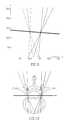
- FIG. 3shows a virtual axial view of the vertebra of FIG. 2 , showing a stripe running from the X-ray source through the marked center of the pedicle;
- FIGS. 4A to 4Cshow further fluoroscope images similar to that of FIG. 2 , but taken from three different obliquely lateral angles;
- FIG. 5shows a virtual axial image of the vertebra, with the projection of the beams of FIGS. 4A to 4C shown in the virtual axial plane;
- FIG. 6shows the procedure illustrated in FIG. 5 but performed for both the left and the right pedicles
- FIG. 7shows schematically an example of a vertebra with four orientations close to the AP direction for use in generating the virtual axial plot shown in FIG. 6 ;
- FIG. 8is a schematic representation of a fluoroscope AP image taken of the spine of a subject, showing the pedicles to be operated on marked by the surgeon;
- FIG. 9is an updated axial plane image on which lines defined by the user selections have been projected.
- FIG. 10shows a schematic representation of a preoperative CT image of the vertebra shown in FIG. 8 , onto which are imposed the lines of FIG. 9 ;
- FIG. 11depicts a safe zone marked in the fluoroscope image of a vertebra to be treated
- FIG. 12shows the paths of FIG. 9 , but broadened to include the surgeon-defined safe zones, such that the thin line paths have become broader swathes to represent the width of the safe zones;
- FIG. 13is a plot similar to that of FIG. 10 , but using the safe zone widths, showing the outcome of superimposing the results obtained from the virtual axial view of FIG. 12 onto a preoperative CT image.
- FIG. 2shows an acquired AP fluoroscopic image of a subject's vertebra.
- the surgical procedure to be performed on this vertebrais the drilling of a screw hole into the pedicle at such an angle that the hole will neither break out of the pedicle, nor enter the spinal channel where serious damage could be caused.
- a spot 20is marked at what appears to the surgeon to represent the best estimated position of the center of the left pedicle 21 .
- the pedicleappears as an elliptical shape due to the concentration of bone density on the cylinder-like pedicle surface.
- the pediclesmay be identified automatically using image processing methods.
- a point drawn on the imagerepresents in the real-life world, a ray between the 3D position of that point in space and the X-ray source, whose position in space is now also known relative to the target.
- this spotthus represents a line running from the X-ray source to the center of the pedicle.
- this virtual lineis shown as a stripe displayed on a virtual axial image of the vertebra being imaged, the line running from the X-ray source 33 to the center of the pedicle 32 , and perpendicular to the image plane 31 .
- the marked spot 30is seen on the image plane when looking into the image.
- the position of this lineis computed relative to the target plate, as the pose of the C-arm source relative to the target can be determined from the position of the opaque spheres of the target on the images.
- FIGS. 4A to 4Cshow further fluoroscope images taken from three different obliquely lateral angles, with the best estimated position of the centers of the pedicle marked on each of them.
- the axial image shown in FIG. 5is not accessible, but using the preferred methods of the present invention, the screws that need to be inserted through the pedicles can still be precisely positioned, even without clearly seeing the axial image itself.
- the robotic control of the screw insertion systemcan be programmed to use the data of the virtual axial image of FIG. 5 , typically to align a drill guide tube in such an orientation that the drilled screw hole will pass through the center of the shaded “safe” region.
- the robotic coordinate systemis registered to the co-ordinate system of the virtual axial image by mounting the robot base in a known position relative to the target. According to one preferred embodiment, this is achieved by mounting the robot base onto the same base as is used to mount the target.
- system and method of the present inventionsimulates the methodology of a regular CT scanning procedure, with the important difference that:
- the procedurecan be performed for both the left and the right pedicles, as shown in FIG. 6 .
- the detailed methodcan be described as follows, again using pedicle screw insertion as a preferred example.
- a single LT fluoroscopic image and at least two, or more advantageously, at least three images at angles preferably close to the AP orientationare taken for each of the pedicles.
- the exact AP imagecan be used for both pedicles, resulting in a total of six preferred images: five of them close to or at the AP orientation, and an LT image, as shown in FIG. 7 .
- the fluoroscopic imagescan be acquired from a video sequence by using a continuous motion mode of the C-arm, and using selected frames for marking by the surgeon.
- the five images typically acquired in the vicinity of the AP directionare used to identify the pedicle positions on the axial plane and to orient the AP direction of the axial plane.
- the AP image itselfis used for both of the pedicles, and two more images are used for each of the pedicles, preferably at the preferred angles shown in FIG. 7 .
- the single LT imageis used to orient the LT direction of the axial plane and to identify the pedicle area in the axial plane.
- Fluoroscope images in the vicinity of the AP orientationshow pedicles as ellipses.
- the surgeonclicks on what he estimates to be the pedicle centers in the relevant images, thereby entering into the system the perceived lines between the X-ray source and the pedicle centers for the alignment of each image.
- Relevant imagesare those where the pedicle cross section is close to being parallel to the image plane, for instance at angles of ⁇ 20°, ⁇ 10°, 0° for the left pedicle and 0°, ⁇ 10°, ⁇ 20° for the right pedicle.
- the pediclesare perceived by the motion created by playing the video sequence.
- FIG. 8is an actual fluoroscope AP image taken of the spine of a subject.
- the pediclesare clearly visible at the outer extremities of the vertebrae, and the pedicles of the vertebra to be operated on have been marked 80 , 81 by the surgeon, preferably using the computing system cursor, whether a mouse, or a touch screen or an alternative marking device.
- Marking a point on such a 2D imageis equivalent to generating a line in real 3D space from the marked point to the X-ray source, whose coordinate relative to the target can be calculated using the distribution of the target's opaque spheres on the X-ray image.
- each linepasses from the X-ray source, through the pedicle center to the image plane, the result of this is the generation of a bundle of lines or strips in space, whose common intersection is the location of the pedicle “safe zone” relative to the target coordinates.
- FIG. 9An updated axial plane image has been generated, on which the lines defined by the user selections have been projected. This is shown in FIG. 9 .
- the dotted and full groups of linesrepresent the spatial lines from the source and through the two respective pedicles.
- the pedicle centersare marked as circles at the intersections of each group of spatial lines.
- a robot located in a known position relative to the targetcan therefore point to the pedicle “safe zone” direction along which the surgeon drills to insert the pedicle screw.
- the robot co-ordinatesis registered to the three dimensional co-ordinate system of the source/pedicle/image-plane lines since the robot has been mounted in a known position and orientation relative to that co-ordinate system, as described hereinabove.
- FIG. 10shows an actual preoperative CT image of the vertebra shown in FIG. 8 , onto which are imposed the lines of FIG. 9 , generated by the system from the pedicle markings on the intraoperative fluoroscope images.
- FIG. 10shows an actual preoperative CT image of the vertebra shown in FIG. 8 , onto which are imposed the lines of FIG. 9 , generated by the system from the pedicle markings on the intraoperative fluoroscope images.
- a safe zone 110is the area to the left and right of the center of the pedicle that the user believes is inside the pedicle. This is shown in the fluoroscope image of a vertebra depicted in FIG. 11 .
- FIG. 13is a plot similar to that of FIG. 10 , but using the safe zone widths, showing the outcome of superimposing the results obtained from the virtual axial view of FIG. 12 , onto a preoperative CT image. The outcome verifies the correctness of the method.
- the outer two horizontal linesrepresent the safe zone selected in the LT image.
- the complete 3D geometry of the images(X-ray and image positions) is known, it is possible to try and solve the inverse problem—the reconstruction of the axial plane from the projections, for example, by using an inverse-Radon transformation, or any other reconstruction method.
- 5 fluoro imagesmay not suffice, and the acquisition process will preferably use a continuous imaging mode of the C-arm, preferably using a video sequence of images. This way, the C-arm is rotated and in a short time, sufficient fluoroscope images are acquired for the reconstruction.
- the pose of each imagewill be determined using the target. According to this preferred method, because of the larger number of images available, a three dimensional volumetric model can be generated even without marking the pedicle, or other anatomic feature of interest.
- the 6 acquired images, or the video sequence acquired in the continuous mode of the C-armcan be used together with a standard 3D template model of the vertebra, and a search performed for a 3D non-rigid transformation that will minimize the discrepancies between the images and the appropriate projection of the transformed model.
Landscapes
- Health & Medical Sciences (AREA)
- Life Sciences & Earth Sciences (AREA)
- Medical Informatics (AREA)
- Engineering & Computer Science (AREA)
- Radiology & Medical Imaging (AREA)
- Biomedical Technology (AREA)
- Biophysics (AREA)
- Nuclear Medicine, Radiotherapy & Molecular Imaging (AREA)
- Optics & Photonics (AREA)
- Pathology (AREA)
- Physics & Mathematics (AREA)
- High Energy & Nuclear Physics (AREA)
- Heart & Thoracic Surgery (AREA)
- Molecular Biology (AREA)
- Surgery (AREA)
- Animal Behavior & Ethology (AREA)
- General Health & Medical Sciences (AREA)
- Public Health (AREA)
- Veterinary Medicine (AREA)
- Apparatus For Radiation Diagnosis (AREA)
Abstract
Description
(ii) A set of several fluoroscopic images, and preferably of 5 to 10 fluoroscopic images is acquired from different angles. The angles are determined according to the specific procedure being performed, but images are typically taken at angular intervals of the order of every 5 to 10 degrees. According to another preferred embodiment of the system, the C-arm is used to acquire a continuous video sequence while the C-arm is rotated, to capture multiple angles, from which are selected the few angles required for performing the preferred methods of the present invention.
(iii) The target is identified in each of the acquired fluoroscopic images, the 3D pose of the X-ray source is computed and for each of the images, the location and angular orientation of the image plane (i.e. the detector (camera) plane) relative to the source is determined. This means that the image planes for images taken at different angles can be related to each other, and the axial view thus constructed.
(iv) Relevant anatomic features in the images are identified and marked (automatically by image processing or manually by the surgeon). Any point selected on a fluoroscope image implies a 3D ray between the 3D location of the X-ray source in the space co-ordinates, and the 3D location of the real-life point which was marked in the fluoroscope image.
(v) Using triangulation of the rays deduced from the different flouroscope images, the 3D pose of the feature itself may be reconstructed in real-life co-ordinate space.
Claims (7)
Priority Applications (1)
| Application Number | Priority Date | Filing Date | Title |
|---|---|---|---|
| US12/442,737US8335553B2 (en) | 2006-09-25 | 2007-09-25 | CT-free spinal surgical imaging system |
Applications Claiming Priority (3)
| Application Number | Priority Date | Filing Date | Title |
|---|---|---|---|
| US84675006P | 2006-09-25 | 2006-09-25 | |
| US12/442,737US8335553B2 (en) | 2006-09-25 | 2007-09-25 | CT-free spinal surgical imaging system |
| PCT/IL2007/001194WO2008038284A2 (en) | 2006-09-25 | 2007-09-25 | Ct-free spinal surgical imaging system |
Publications (2)
| Publication Number | Publication Date |
|---|---|
| US20100106010A1 US20100106010A1 (en) | 2010-04-29 |
| US8335553B2true US8335553B2 (en) | 2012-12-18 |
Family
ID=39230677
Family Applications (1)
| Application Number | Title | Priority Date | Filing Date |
|---|---|---|---|
| US12/442,737Active2029-05-26US8335553B2 (en) | 2006-09-25 | 2007-09-25 | CT-free spinal surgical imaging system |
Country Status (3)
| Country | Link |
|---|---|
| US (1) | US8335553B2 (en) |
| CN (1) | CN101542240A (en) |
| WO (1) | WO2008038284A2 (en) |
Cited By (20)
| Publication number | Priority date | Publication date | Assignee | Title |
|---|---|---|---|---|
| US9129054B2 (en) | 2012-09-17 | 2015-09-08 | DePuy Synthes Products, Inc. | Systems and methods for surgical and interventional planning, support, post-operative follow-up, and, functional recovery tracking |
| US10552197B2 (en) | 2018-01-25 | 2020-02-04 | International Business Machines Corporation | Inexact reconstitution of virtual machine images |
| US10966736B2 (en) | 2018-05-21 | 2021-04-06 | Warsaw Orthopedic, Inc. | Spinal implant system and methods of use |
| US11033341B2 (en) | 2017-05-10 | 2021-06-15 | Mako Surgical Corp. | Robotic spine surgery system and methods |
| US11065069B2 (en) | 2017-05-10 | 2021-07-20 | Mako Surgical Corp. | Robotic spine surgery system and methods |
| US11750794B2 (en) | 2015-03-24 | 2023-09-05 | Augmedics Ltd. | Combining video-based and optic-based augmented reality in a near eye display |
| US11766296B2 (en) | 2018-11-26 | 2023-09-26 | Augmedics Ltd. | Tracking system for image-guided surgery |
| US11801115B2 (en) | 2019-12-22 | 2023-10-31 | Augmedics Ltd. | Mirroring in image guided surgery |
| US11896445B2 (en) | 2021-07-07 | 2024-02-13 | Augmedics Ltd. | Iliac pin and adapter |
| US11974887B2 (en) | 2018-05-02 | 2024-05-07 | Augmedics Ltd. | Registration marker for an augmented reality system |
| US11980506B2 (en) | 2019-07-29 | 2024-05-14 | Augmedics Ltd. | Fiducial marker |
| US12044858B2 (en) | 2022-09-13 | 2024-07-23 | Augmedics Ltd. | Adjustable augmented reality eyewear for image-guided medical intervention |
| US12150821B2 (en) | 2021-07-29 | 2024-11-26 | Augmedics Ltd. | Rotating marker and adapter for image-guided surgery |
| US12178666B2 (en) | 2019-07-29 | 2024-12-31 | Augmedics Ltd. | Fiducial marker |
| US12186028B2 (en) | 2020-06-15 | 2025-01-07 | Augmedics Ltd. | Rotating marker for image guided surgery |
| US12239385B2 (en) | 2020-09-09 | 2025-03-04 | Augmedics Ltd. | Universal tool adapter |
| KR20250036649A (en) | 2023-09-07 | 2025-03-14 | 큐렉소 주식회사 | Method of image based 3d-automatic planning of operation and system adopting the method |
| KR20250037707A (en) | 2023-09-07 | 2025-03-18 | 큐렉소 주식회사 | Image-based 3D automatic surgical planning method and system |
| US12354227B2 (en) | 2022-04-21 | 2025-07-08 | Augmedics Ltd. | Systems for medical image visualization |
| US12417595B2 (en) | 2021-08-18 | 2025-09-16 | Augmedics Ltd. | Augmented-reality surgical system using depth sensing |
Families Citing this family (24)
| Publication number | Priority date | Publication date | Assignee | Title |
|---|---|---|---|---|
| US8992580B2 (en) | 2008-12-01 | 2015-03-31 | Mazor Robotics Ltd. | Robot guided oblique spinal stabilization |
| WO2011088284A1 (en) | 2010-01-14 | 2011-07-21 | Synthes Usa, Llc | System and methods for minimally invasive spine surgery |
| CA2797302C (en) | 2010-04-28 | 2019-01-15 | Ryerson University | System and methods for intraoperative guidance feedback |
| US9510771B1 (en) | 2011-10-28 | 2016-12-06 | Nuvasive, Inc. | Systems and methods for performing spine surgery |
| CN103839032B (en)* | 2012-11-20 | 2018-03-23 | 联想(北京)有限公司 | A kind of recognition methods and electronic equipment |
| US9848922B2 (en) | 2013-10-09 | 2017-12-26 | Nuvasive, Inc. | Systems and methods for performing spine surgery |
| JP6267931B2 (en)* | 2013-11-01 | 2018-01-24 | 株式会社日立製作所 | X-ray diagnostic equipment |
| US10709509B2 (en) | 2014-06-17 | 2020-07-14 | Nuvasive, Inc. | Systems and methods for planning, performing, and assessing spinal correction during surgery |
| DE102016201701A1 (en) | 2015-02-24 | 2016-08-25 | Siemens Aktiengesellschaft | Mobile, motor-driven medical device and method for operating such a device |
| US10070928B2 (en)* | 2015-07-01 | 2018-09-11 | Mako Surgical Corp. | Implant placement planning |
| ITUB20152877A1 (en)* | 2015-07-22 | 2017-01-22 | Techno Design S R L | Method for identifying the optimal direction and maximum diameter of a pedicle screw so that the screw does not come out of the pedicle during insertion. |
| CN120419981A (en) | 2016-03-13 | 2025-08-05 | 乌泽医疗有限公司 | Devices and methods for use with bone surgery |
| US11406338B2 (en) | 2017-07-08 | 2022-08-09 | Vuze Medical Ltd. | Apparatus and methods for use with image-guided skeletal procedures |
| US10702217B2 (en)* | 2017-08-24 | 2020-07-07 | General Electric Company | System and method for imaging a patient |
| EP3713491B1 (en)* | 2017-11-22 | 2025-02-26 | Mazor Robotics Ltd. | A system for verifying hard tissue location using implant imaging |
| CN108648821B (en)* | 2018-03-21 | 2020-12-01 | 北京理工大学 | Intelligent surgical decision-making system for puncture surgical robot and its application method |
| EP3608870A1 (en) | 2018-08-10 | 2020-02-12 | Holo Surgical Inc. | Computer assisted identification of appropriate anatomical structure for medical device placement during a surgical procedure |
| KR102166149B1 (en)* | 2019-03-13 | 2020-10-15 | 큐렉소 주식회사 | Pedicle screw fixation planning system and method thereof |
| EP3946059B1 (en)* | 2019-03-25 | 2022-10-19 | Koninklijke Philips N.V. | X-ray ring markers for x-ray calibration |
| FR3108419A1 (en)* | 2020-03-18 | 2021-09-24 | Pytheas Navigation | Method and device for assisting an invasive intervention on a human or animal organ |
| US12347100B2 (en) | 2020-11-19 | 2025-07-01 | Mazor Robotics Ltd. | Systems and methods for generating virtual images |
| EP4011311A1 (en)* | 2020-12-14 | 2022-06-15 | Incremed AG | Method for planning the nail path of a pedicle bone screw |
| WO2023047355A1 (en)* | 2021-09-26 | 2023-03-30 | Augmedics Ltd. | Surgical planning and display |
| EP4477180A1 (en)* | 2023-06-16 | 2024-12-18 | metamorphosis GmbH | System and methods for distinguishing angular sections of viewing directions |
Citations (13)
| Publication number | Priority date | Publication date | Assignee | Title |
|---|---|---|---|---|
| US6198794B1 (en)* | 1996-05-15 | 2001-03-06 | Northwestern University | Apparatus and method for planning a stereotactic surgical procedure using coordinated fluoroscopy |
| US20020082492A1 (en)* | 2000-09-07 | 2002-06-27 | Robert Grzeszczuk | Fast mapping of volumetric density data onto a two-dimensional screen |
| US6423077B2 (en)* | 1994-09-30 | 2002-07-23 | Ohio Medical Instrument Company, Inc. | Apparatus and method for surgical stereotactic procedures |
| US20030073901A1 (en)* | 1999-03-23 | 2003-04-17 | Simon David A. | Navigational guidance via computer-assisted fluoroscopic imaging |
| US20040171924A1 (en) | 2003-01-30 | 2004-09-02 | Mire David A. | Method and apparatus for preplanning a surgical procedure |
| US6837892B2 (en) | 2000-07-24 | 2005-01-04 | Mazor Surgical Technologies Ltd. | Miniature bone-mounted surgical robot |
| US20050245817A1 (en)* | 2004-05-03 | 2005-11-03 | Clayton John B | Method and apparatus for implantation between two vertebral bodies |
| US20060050943A1 (en)* | 2002-12-03 | 2006-03-09 | Masahiro Ozaki | Computer-aided diagnostic apparatus |
| US20060098851A1 (en) | 2002-06-17 | 2006-05-11 | Moshe Shoham | Robot for use with orthopaedic inserts |
| WO2006075331A2 (en) | 2005-01-13 | 2006-07-20 | Mazor Surgical Technologies Ltd. | Image-guided robotic system for keyhole neurosurgery |
| US20070100258A1 (en) | 2003-05-16 | 2007-05-03 | Moshe Shoham | Robotic total/partial knee arthroplastics |
| US20080071272A1 (en) | 2003-10-06 | 2008-03-20 | Mazor Surgical Technologies, Ltd. | Apparatus for Spinal Fixation of Vertebrae |
| WO2008038283A2 (en) | 2006-09-25 | 2008-04-03 | Mazor Surgical Technologies Ltd. | C-arm computerized tomography system |
- 2007
- 2007-09-25USUS12/442,737patent/US8335553B2/enactiveActive
- 2007-09-25CNCNA2007800397673Apatent/CN101542240A/enactivePending
- 2007-09-25WOPCT/IL2007/001194patent/WO2008038284A2/enactiveApplication Filing
Patent Citations (13)
| Publication number | Priority date | Publication date | Assignee | Title |
|---|---|---|---|---|
| US6423077B2 (en)* | 1994-09-30 | 2002-07-23 | Ohio Medical Instrument Company, Inc. | Apparatus and method for surgical stereotactic procedures |
| US6198794B1 (en)* | 1996-05-15 | 2001-03-06 | Northwestern University | Apparatus and method for planning a stereotactic surgical procedure using coordinated fluoroscopy |
| US20030073901A1 (en)* | 1999-03-23 | 2003-04-17 | Simon David A. | Navigational guidance via computer-assisted fluoroscopic imaging |
| US6837892B2 (en) | 2000-07-24 | 2005-01-04 | Mazor Surgical Technologies Ltd. | Miniature bone-mounted surgical robot |
| US20020082492A1 (en)* | 2000-09-07 | 2002-06-27 | Robert Grzeszczuk | Fast mapping of volumetric density data onto a two-dimensional screen |
| US20060098851A1 (en) | 2002-06-17 | 2006-05-11 | Moshe Shoham | Robot for use with orthopaedic inserts |
| US20060050943A1 (en)* | 2002-12-03 | 2006-03-09 | Masahiro Ozaki | Computer-aided diagnostic apparatus |
| US20040171924A1 (en) | 2003-01-30 | 2004-09-02 | Mire David A. | Method and apparatus for preplanning a surgical procedure |
| US20070100258A1 (en) | 2003-05-16 | 2007-05-03 | Moshe Shoham | Robotic total/partial knee arthroplastics |
| US20080071272A1 (en) | 2003-10-06 | 2008-03-20 | Mazor Surgical Technologies, Ltd. | Apparatus for Spinal Fixation of Vertebrae |
| US20050245817A1 (en)* | 2004-05-03 | 2005-11-03 | Clayton John B | Method and apparatus for implantation between two vertebral bodies |
| WO2006075331A2 (en) | 2005-01-13 | 2006-07-20 | Mazor Surgical Technologies Ltd. | Image-guided robotic system for keyhole neurosurgery |
| WO2008038283A2 (en) | 2006-09-25 | 2008-04-03 | Mazor Surgical Technologies Ltd. | C-arm computerized tomography system |
Non-Patent Citations (1)
| Title |
|---|
| PCT Int'l Search Report mailed Aug. 20, 2008 and Written Opinion of the ISA, mailed Aug. 20, 2008 in PCT/IL2007/01194. |
Cited By (43)
| Publication number | Priority date | Publication date | Assignee | Title |
|---|---|---|---|---|
| US11749396B2 (en) | 2012-09-17 | 2023-09-05 | DePuy Synthes Products, Inc. | Systems and methods for surgical and interventional planning, support, post-operative follow-up, and, functional recovery tracking |
| US9700292B2 (en) | 2012-09-17 | 2017-07-11 | DePuy Synthes Products, Inc. | Systems and methods for surgical and interventional planning, support, post-operative follow-up, and functional recovery tracking |
| US10166019B2 (en) | 2012-09-17 | 2019-01-01 | DePuy Synthes Products, Inc. | Systems and methods for surgical and interventional planning, support, post-operative follow-up, and, functional recovery tracking |
| US11923068B2 (en) | 2012-09-17 | 2024-03-05 | DePuy Synthes Products, Inc. | Systems and methods for surgical and interventional planning, support, post-operative follow-up, and functional recovery tracking |
| US10595844B2 (en) | 2012-09-17 | 2020-03-24 | DePuy Synthes Products, Inc. | Systems and methods for surgical and interventional planning, support, post-operative follow-up, and functional recovery tracking |
| US9129054B2 (en) | 2012-09-17 | 2015-09-08 | DePuy Synthes Products, Inc. | Systems and methods for surgical and interventional planning, support, post-operative follow-up, and, functional recovery tracking |
| US11798676B2 (en) | 2012-09-17 | 2023-10-24 | DePuy Synthes Products, Inc. | Systems and methods for surgical and interventional planning, support, post-operative follow-up, and functional recovery tracking |
| US12069233B2 (en) | 2015-03-24 | 2024-08-20 | Augmedics Ltd. | Head-mounted augmented reality near eye display device |
| US12206837B2 (en) | 2015-03-24 | 2025-01-21 | Augmedics Ltd. | Combining video-based and optic-based augmented reality in a near eye display |
| US12063345B2 (en) | 2015-03-24 | 2024-08-13 | Augmedics Ltd. | Systems for facilitating augmented reality-assisted medical procedures |
| US11750794B2 (en) | 2015-03-24 | 2023-09-05 | Augmedics Ltd. | Combining video-based and optic-based augmented reality in a near eye display |
| US12035985B2 (en) | 2017-05-10 | 2024-07-16 | Mako Surgical Corp. | Robotic spine surgery system and methods |
| US11701188B2 (en) | 2017-05-10 | 2023-07-18 | Mako Surgical Corp. | Robotic spine surgery system and methods |
| US11065069B2 (en) | 2017-05-10 | 2021-07-20 | Mako Surgical Corp. | Robotic spine surgery system and methods |
| US11033341B2 (en) | 2017-05-10 | 2021-06-15 | Mako Surgical Corp. | Robotic spine surgery system and methods |
| US11937889B2 (en) | 2017-05-10 | 2024-03-26 | Mako Surgical Corp. | Robotic spine surgery system and methods |
| US11200083B2 (en) | 2018-01-25 | 2021-12-14 | International Business Machines Corporation | Inexact reconstitution of virtual machine images |
| US10552197B2 (en) | 2018-01-25 | 2020-02-04 | International Business Machines Corporation | Inexact reconstitution of virtual machine images |
| US11974887B2 (en) | 2018-05-02 | 2024-05-07 | Augmedics Ltd. | Registration marker for an augmented reality system |
| US11980507B2 (en) | 2018-05-02 | 2024-05-14 | Augmedics Ltd. | Registration of a fiducial marker for an augmented reality system |
| US12290416B2 (en) | 2018-05-02 | 2025-05-06 | Augmedics Ltd. | Registration of a fiducial marker for an augmented reality system |
| US11980508B2 (en) | 2018-05-02 | 2024-05-14 | Augmedics Ltd. | Registration of a fiducial marker for an augmented reality system |
| US10966736B2 (en) | 2018-05-21 | 2021-04-06 | Warsaw Orthopedic, Inc. | Spinal implant system and methods of use |
| US11980429B2 (en) | 2018-11-26 | 2024-05-14 | Augmedics Ltd. | Tracking methods for image-guided surgery |
| US11766296B2 (en) | 2018-11-26 | 2023-09-26 | Augmedics Ltd. | Tracking system for image-guided surgery |
| US12201384B2 (en) | 2018-11-26 | 2025-01-21 | Augmedics Ltd. | Tracking systems and methods for image-guided surgery |
| US11980506B2 (en) | 2019-07-29 | 2024-05-14 | Augmedics Ltd. | Fiducial marker |
| US12178666B2 (en) | 2019-07-29 | 2024-12-31 | Augmedics Ltd. | Fiducial marker |
| US11801115B2 (en) | 2019-12-22 | 2023-10-31 | Augmedics Ltd. | Mirroring in image guided surgery |
| US12076196B2 (en) | 2019-12-22 | 2024-09-03 | Augmedics Ltd. | Mirroring in image guided surgery |
| US12383369B2 (en) | 2019-12-22 | 2025-08-12 | Augmedics Ltd. | Mirroring in image guided surgery |
| US12186028B2 (en) | 2020-06-15 | 2025-01-07 | Augmedics Ltd. | Rotating marker for image guided surgery |
| US12239385B2 (en) | 2020-09-09 | 2025-03-04 | Augmedics Ltd. | Universal tool adapter |
| US11896445B2 (en) | 2021-07-07 | 2024-02-13 | Augmedics Ltd. | Iliac pin and adapter |
| US12150821B2 (en) | 2021-07-29 | 2024-11-26 | Augmedics Ltd. | Rotating marker and adapter for image-guided surgery |
| US12417595B2 (en) | 2021-08-18 | 2025-09-16 | Augmedics Ltd. | Augmented-reality surgical system using depth sensing |
| US12354227B2 (en) | 2022-04-21 | 2025-07-08 | Augmedics Ltd. | Systems for medical image visualization |
| US12412346B2 (en) | 2022-04-21 | 2025-09-09 | Augmedics Ltd. | Methods for medical image visualization |
| US12044856B2 (en) | 2022-09-13 | 2024-07-23 | Augmedics Ltd. | Configurable augmented reality eyewear for image-guided medical intervention |
| US12044858B2 (en) | 2022-09-13 | 2024-07-23 | Augmedics Ltd. | Adjustable augmented reality eyewear for image-guided medical intervention |
| KR20250037707A (en) | 2023-09-07 | 2025-03-18 | 큐렉소 주식회사 | Image-based 3D automatic surgical planning method and system |
| KR20250036648A (en) | 2023-09-07 | 2025-03-14 | 큐렉소 주식회사 | Method of 2d-image based automatic planning of operation and system adopting the method |
| KR20250036649A (en) | 2023-09-07 | 2025-03-14 | 큐렉소 주식회사 | Method of image based 3d-automatic planning of operation and system adopting the method |
Also Published As
| Publication number | Publication date |
|---|---|
| US20100106010A1 (en) | 2010-04-29 |
| WO2008038284A2 (en) | 2008-04-03 |
| WO2008038284A3 (en) | 2009-05-07 |
| CN101542240A (en) | 2009-09-23 |
Similar Documents
| Publication | Publication Date | Title |
|---|---|---|
| US8335553B2 (en) | CT-free spinal surgical imaging system | |
| US12268548B2 (en) | Systems and methods for producing real-time calibrated stereo long radiographic views of a patient on a surgical table | |
| JP7204663B2 (en) | Systems, apparatus, and methods for improving surgical accuracy using inertial measurement devices | |
| EP3917432B1 (en) | System for registration between coordinate systems and navigation of selected members | |
| US11426242B2 (en) | System and method for registration between coordinate systems and navigation of selected members | |
| AU2018290995B2 (en) | System and method for identifying, marking and navigating to a target using real-time two-dimensional fluoroscopic data | |
| EP3127485B1 (en) | System for local three dimensional volume reconstruction using a standard fluoroscope | |
| JP5121401B2 (en) | System for distance measurement of buried plant | |
| US11672607B2 (en) | Systems, devices, and methods for surgical navigation with anatomical tracking | |
| JP2022516642A (en) | Systems and methods for alignment of coordinate system and navigation | |
| US20080119725A1 (en) | Systems and Methods for Visual Verification of CT Registration and Feedback | |
| US20240144497A1 (en) | 3D Spatial Mapping in a 3D Coordinate System of an AR Headset Using 2D Images | |
| US20110071389A1 (en) | System and Method for Automatic Registration Between an Image and a Subject | |
| US20080119712A1 (en) | Systems and Methods for Automated Image Registration | |
| CN115475005A (en) | Technique for generating surgical information from intraoperative and preoperative acquired image data | |
| US20240386682A1 (en) | 3D Alignment in a 3D Coordinate System of an AR Headset Using 2D Reference Images | |
| US20080119724A1 (en) | Systems and methods for intraoperative implant placement analysis | |
| KR100726022B1 (en) | 3D Surgical Space Measurement System and Method Using Multiple 2D Images | |
| WO2012052929A2 (en) | System and method for facilitating navigation of a tool using a fluoroscope | |
| Lopukhov et al. | Computer‐Guided Navigation System Efficiency Evaluation Using Surgical Instruments for Spinal Fusion | |
| CN114533267A (en) | 2D image surgery positioning navigation system and method | |
| Wang et al. | First animal cadaver study for interlocking of intramedullary nails under camera augmented mobile c-arm: a surgical workflow based preclinical evaluation | |
| JP2022521615A (en) | Intervention device tracking | |
| JP2009172124A (en) | Surgical navigation system, image display method, computer program, and recording medium | |
| US20250040991A1 (en) | Method and Device for an Improved Display in a Manual or a Robot Assisted Intervention in a Region of Interest of the Patient |
Legal Events
| Date | Code | Title | Description |
|---|---|---|---|
| AS | Assignment | Owner name:MAZOR SURGICAL TECHNOLOGIES LTD.,ISRAEL Free format text:ASSIGNMENT OF ASSIGNORS INTEREST;ASSIGNORS:RUBNER, JOSEPH;ZEHAVI, ELI;KLEYMAN, LEONID;AND OTHERS;REEL/FRAME:023840/0274 Effective date:20090422 Owner name:MAZOR SURGICAL TECHNOLOGIES LTD., ISRAEL Free format text:ASSIGNMENT OF ASSIGNORS INTEREST;ASSIGNORS:RUBNER, JOSEPH;ZEHAVI, ELI;KLEYMAN, LEONID;AND OTHERS;REEL/FRAME:023840/0274 Effective date:20090422 | |
| AS | Assignment | Owner name:MAZOR SURGICAL ROBOTICS LTD., ISRAEL Free format text:CHANGE OF NAME;ASSIGNOR:MAZOR SURGICAL TECHNOLOGIES LTD.;REEL/FRAME:029065/0911 Effective date:20100822 | |
| AS | Assignment | Owner name:MAZOR ROBOTICS LTD., ISRAEL Free format text:CHANGE OF NAME;ASSIGNOR:MAZOR SURGICAL ROBOTICS LTD.;REEL/FRAME:029125/0423 Effective date:20101125 | |
| STCF | Information on status: patent grant | Free format text:PATENTED CASE | |
| REMI | Maintenance fee reminder mailed | ||
| FPAY | Fee payment | Year of fee payment:4 | |
| SULP | Surcharge for late payment | ||
| MAFP | Maintenance fee payment | Free format text:PAYMENT OF MAINTENANCE FEE, 8TH YR, SMALL ENTITY (ORIGINAL EVENT CODE: M2552); ENTITY STATUS OF PATENT OWNER: SMALL ENTITY Year of fee payment:8 | |
| FEPP | Fee payment procedure | Free format text:ENTITY STATUS SET TO UNDISCOUNTED (ORIGINAL EVENT CODE: BIG.); ENTITY STATUS OF PATENT OWNER: LARGE ENTITY | |
| MAFP | Maintenance fee payment | Free format text:PAYMENT OF MAINTENANCE FEE, 12TH YEAR, LARGE ENTITY (ORIGINAL EVENT CODE: M1553); ENTITY STATUS OF PATENT OWNER: LARGE ENTITY Year of fee payment:12 |