US8335394B2 - Image processing method for boundary resolution enhancement - Google Patents
Image processing method for boundary resolution enhancementDownload PDFInfo
- Publication number
- US8335394B2 US8335394B2US12/748,058US74805810AUS8335394B2US 8335394 B2US8335394 B2US 8335394B2US 74805810 AUS74805810 AUS 74805810AUS 8335394 B2US8335394 B2US 8335394B2
- Authority
- US
- United States
- Prior art keywords
- image
- processing method
- image layer
- image processing
- resolution
- Prior art date
- Legal status (The legal status is an assumption and is not a legal conclusion. Google has not performed a legal analysis and makes no representation as to the accuracy of the status listed.)
- Active, expires
Links
Images
Classifications
- G—PHYSICS
- G06—COMPUTING OR CALCULATING; COUNTING
- G06T—IMAGE DATA PROCESSING OR GENERATION, IN GENERAL
- G06T5/00—Image enhancement or restoration
- G06T5/73—Deblurring; Sharpening
- G—PHYSICS
- G06—COMPUTING OR CALCULATING; COUNTING
- G06T—IMAGE DATA PROCESSING OR GENERATION, IN GENERAL
- G06T5/00—Image enhancement or restoration
- G06T5/70—Denoising; Smoothing
- G—PHYSICS
- G06—COMPUTING OR CALCULATING; COUNTING
- G06T—IMAGE DATA PROCESSING OR GENERATION, IN GENERAL
- G06T3/00—Geometric image transformations in the plane of the image
- G06T3/40—Scaling of whole images or parts thereof, e.g. expanding or contracting
- G06T3/403—Edge-driven scaling; Edge-based scaling
- G—PHYSICS
- G06—COMPUTING OR CALCULATING; COUNTING
- G06T—IMAGE DATA PROCESSING OR GENERATION, IN GENERAL
- G06T5/00—Image enhancement or restoration
- G06T5/20—Image enhancement or restoration using local operators
- G—PHYSICS
- G06—COMPUTING OR CALCULATING; COUNTING
- G06T—IMAGE DATA PROCESSING OR GENERATION, IN GENERAL
- G06T2207/00—Indexing scheme for image analysis or image enhancement
- G06T2207/20—Special algorithmic details
- G06T2207/20024—Filtering details
- G06T2207/20028—Bilateral filtering
- G—PHYSICS
- G06—COMPUTING OR CALCULATING; COUNTING
- G06T—IMAGE DATA PROCESSING OR GENERATION, IN GENERAL
- G06T2207/00—Indexing scheme for image analysis or image enhancement
- G06T2207/20—Special algorithmic details
- G06T2207/20172—Image enhancement details
- G06T2207/20192—Edge enhancement; Edge preservation
Definitions
- the present inventionrelates to an image processing method, and in particular to an image process method for boundary resolution enhancement which can suitable to implement in many kinds of mother boards, display cards or image processing device.
- the display screens with the old style of cathode ray tubesare gradually replaced by the flat display panels which are Liquid Crystal or Plasma.
- Most of these display deviceshave High Definition (HD) resolution (1920 ⁇ 1080p), but the resolution of some video formats especially for the old broadcasting programs belongs to Standard Definition (SD) lower than High Definition resolution. Therefore, in order to maintain the display performance when the video format with Standard Definition resolution is inputted on the display device with High Definition resolution, the problem of fitting the video format for the display device has to be solved.
- Video upsampling method and super resolution methodcan be utilized to input the low resolution video format on the high definition devices.
- the image/video resolution up-conversion filter based methodis capable of supporting the processing of image edges texture artifacts, and noise.
- the existed image/video resolution up-conversion methodscomprise linear methods and non-linear methods.
- One of the linear methodsis a bilinear interpolation method. It has low cost and reducing artifact and blurring degree of an image so the most graphic cards have integrated the bilinear interpolation into the chipset.
- the bilinear interpolation methodstill has strong overshoot issues on edges and boundaries, and the artifact cannot be totally removed.
- the non-linear methodseffectively overcome the shortcomings of the linear method but the fine details are still blurring.
- the present inventionprovides an image processing method for boundary resolution enhancement to transfer the low resolution image into a high resolution one for displaying on high resolution devices.
- the complexity of the present inventionis low enough to implement it in all kinds of display devices and image/video processing hardware devices.
- An objective of the present inventionis to disclose an image processing method for boundary resolution enhancement which is capable of substantially decreasing trickle noise, and overshoot and artifact compression issues for reducing image blurring degree and enhancing image resolution.
- the complexity of the image processing method of the present inventionis so low that the computation is not heavy and the present invention has great practicability because it can be implemented in central processing units, image processing chips, mother boards, display cards and digital image processing units.
- the present inventiondiscloses an image processing method for boundary resolution enhancement which comprises steps: transferring an image into an image layer; smoothly removing trickle noise which is small illuminance variation of the image layer and retain boundaries which is large illuminance variation to generate a resolution image layer by a bilateral filter; dividing each pixel of the resolution image layer by using data dependent triangulation, wherein each pixel has a diagonal line, the resolution image layer is divided into a plurality of horizontal blocks and vertical blocks, the resolution image layer is divided into a plurality of horizontal pixel fields and vertical pixel fields which are based on the diagonal lines, the horizontal pixel fields and the vertical pixel fields are formed through a gradient process executed by a sharpness filter for removing unbalance boundaries of the resolution image layer and generating a sharpened image layer; and center pixel points of the horizontal and vertical pixel fields and opponent pixel points relative to the center pixel points are interpolated by an interpolation filter using interpolation pixels so that a high resolution image layer is generated.
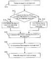
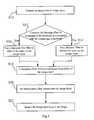
- FIG. 1is a flow chart for enhancing image boundary resolution according to the present invention
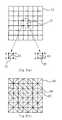
- FIG. 2( a )is a diagram for pixels divided by Data Dependent Triangulation according to the present invention
- FIG. 2( b )is a diagram for a resolution image divided by Data Dependent Triangulation according to the present invention
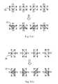
- FIG. 3( a )is a diagram that the resolution image is divided into horizontal blocks and horizontal pixel fields are formed.
- FIG. 3( b )is a diagram that the resolution image is divided into vertical blocks and vertical pixel fields are formed.
- the present inventionprovides an image processing method for boundary resolution enhancement, which utilizes a bilateral filter to remove trickle noise of an image layer, and to retain crisp edges of the image layer. Then, a sharpness filter performs a gradient analysis of the image layer to reduce artifacts resulting in unbalance boundaries and to enhance texture and edge details. Finally, an interpolation filter is used to interpolate the image layer for increasing the image resolution.
- a bilateral filterto remove trickle noise of an image layer
- a sharpness filterperforms a gradient analysis of the image layer to reduce artifacts resulting in unbalance boundaries and to enhance texture and edge details.
- an interpolation filteris used to interpolate the image layer for increasing the image resolution.
- FIG. 1is a flow chart of the image processing method for boundary resolution enhancement according to the present invention. Firstly, in Step S 10 , an image is transferred into an image layer which is RGB format, YUV format, or CIE-Lab format.
- Step S 12blurring effect of the image layer is computed.
- the computing complexity which the image layer is filtered by the bilateral filteris predicted to determine the load of the hardware.
- the noise of the image layeris removed by an Inverted Intensity Gaussian Bilateral Filter (IIG Bilateral Filter) to generate a resolution image layer.
- IIG Bilateral FilterInverted Intensity Gaussian Bilateral Filter
- Step S 18use a sharpness filter to perform a gradient analysis of the resolution image layer, remove unbalance boundaries generating overshoot issues in the resolution image layer, and enhance the texture and edges details of the resolution image layer so as to generate a sharpened image layer.
- Step S 20the method continues with using an interpolation filter to interpolate the sharpened image layer.
- a high resolution image layeris subsequently generated.
- Step S 22the high resolution image layer, which is formed from the resolution image processed through the filtering, the sharpening, and the interpolating procedures, is transferred back to the original format of the image such that the high resolution image layer after transferred can be displayed with high definition resolution on display devices.
- the inverted intensity Gaussian bilateral filtercomprises a horizontal Invert Intensity Gaussian Bilateral Filter and a vertical Invert Intensity Gaussian Bilateral Filter.
- the image layeris filtered horizontally by the horizontal Invert Intensity Gaussian Bilateral Filter, and then it is filtered vertically by the vertical Invert Intensity Gaussian Bilateral Filter, such that the noise of the image layer can be removed and the resolution image layer can be generated from the image layer.
- the design of the Invert Intensity Gaussian Bilateral Filteris shown in derived as the following equations:
- Equation (1)indicates the enhancement of intensity value of a pixel (c) can be obtained by integrating intensity domain and spatial domain of a pixel (c) itself and intensity domain and spatial domain of a neighbor pixel (a).
- the invert intensity Gaussian bilateral filterfilters the image layer repeatedly until the intensity variation is lower than a filtering threshold or reaches zero.
- Equation (2) and Equation (3)represent an intensity domain variation curve of the intensity value of a reflect pixel (a) and a reflect neighbor pixel (c), and a spatial domain variation curve of the intensity value of the reflected pixel (a) and intensity value of the reflected adjacent pixel (c).
- the distance function D(.)can be an Euclidean distance function
- Ccan be set 0.004 for eight bit depth video.
- Equation (2) and Equation (3)are substituted into Equation (1) to generate Equation (4) which means the spatial domain and the intensity domain of the pixels are simultaneously processed with a Gaussian blurred algorithm in the image layer.
- the noise of small illsuminance variationis smoothly removed from the image layer and the edge of large illsuminance variation is retained in it. Subsequently, the resolution image layer is generated.
- the gradient analysis of the resolution image layeris performed by the sharpness filter, the pixels of the resolution image layer are divided by utilizing Data Dependent Triangulation (DDT) to provide each pixel with a diagonal line.
- DDTData Dependent Triangulation
- Each pixel 12 of the resolution image layer 10is represented by four points a, b, c, d.
- the resolution image layer 10is divided into a plurality of 2 ⁇ 2 horizontal blocks and a plurality of horizontal pixel fields 22 are formed along the diagonal line 14 , so that the 2 ⁇ 2 horizontal pixel fields 20 become 2 ⁇ 3 horizontal blocks 20 and each of horizontal pixel fields 22 has a center pixel point P 0 and an opponent pixel point P 2 relative to the center pixel point P 0 . Because of the different slopes of the diagonal lines 14 , the shapes of the horizontal pixel fields 22 based on the diagonal lines 14 are different. If the two adjacent diagonal lines 14 have an intersecting point, the shape of the horizontal pixel field is a triangle. If the two adjacent diagonal lines 14 are parallel to each other, the shape of the horizontal pixel fields is a quadrilateral shape. After creating the horizontal pixel fields 22 , a gradient horizontal analysis are performed in the horizontal pixel fields 22 by a high pass sharpened filter.
- the resolution image layer that the sharpened filter has already performed the gradient horizontal analysisis divided into a plurality of 2 ⁇ 2 vertical blocks 30 and a plurality of vertical pixel fields 32 are formed through utilizing the diagonal lines 14 , such that the 2 ⁇ 2 vertical blocks 30 becomes 3 ⁇ 2 vertical blocks 30 .
- a vertical gradient analysisis performed in the vertical pixel fields 32 .
- each of the vertical pixel fields 32similar to the case of each of the horizontal pixel fields 22 , also has a center pixel point P 0 and a relative pixel point P 2 , and the vertical pixel fields is in a triangular or quadrilateral shape based on the different slopes of the diagonal lines.
- the sharpened image layeris interpolated by an interpolation filter for raising the resolution.
- the interpolation filtercomputes the center pixel points P 0 and the relative pixel points P 2 in the horizontal pixel fields 22 and the vertical pixel fields 30 to interpolate the pixels and then to generate a high resolution image layer.
- an image layer transferred from an imageis processed through the image process procedures, such as a filter process, a gradient analysis and a resolution enhancement so as to enhance the image boundaries resolution and lower the image blurring degree image.
- the computing complexity in the present inventionis so low that it can be popular in many kinds of image processing device.
Landscapes
- Physics & Mathematics (AREA)
- General Physics & Mathematics (AREA)
- Engineering & Computer Science (AREA)
- Theoretical Computer Science (AREA)
- Image Processing (AREA)
Abstract
Description
whereas B(.) is a pixel's intensity value, c is a pixel, a is a neighbor pixel of c, I(.) returns a pixel's intensity value of the CIE-LAB color space or RGB space, P(.) returns the position of a pixel, f(.) is a spatial filtering function and g(.) is an intensity filtering function, D(.) is a distance function, and c is a constant.
Claims (16)
Priority Applications (1)
| Application Number | Priority Date | Filing Date | Title |
|---|---|---|---|
| US13/718,998US8837854B2 (en) | 2010-01-29 | 2012-12-18 | Image processing method for boundary resolution enhancement |
Applications Claiming Priority (3)
| Application Number | Priority Date | Filing Date | Title |
|---|---|---|---|
| TW99102602A | 2010-01-29 | ||
| TW099102602 | 2010-01-29 | ||
| TW099102602ATWI406571B (en) | 2010-01-29 | 2010-01-29 | Image Processing Method for Enhancing Image Edge Resolution |
Related Child Applications (1)
| Application Number | Title | Priority Date | Filing Date |
|---|---|---|---|
| US13/718,998ContinuationUS8837854B2 (en) | 2010-01-29 | 2012-12-18 | Image processing method for boundary resolution enhancement |
Publications (2)
| Publication Number | Publication Date |
|---|---|
| US20110188749A1 US20110188749A1 (en) | 2011-08-04 |
| US8335394B2true US8335394B2 (en) | 2012-12-18 |
Family
ID=44341706
Family Applications (2)
| Application Number | Title | Priority Date | Filing Date |
|---|---|---|---|
| US12/748,058Active2031-06-17US8335394B2 (en) | 2010-01-29 | 2010-03-26 | Image processing method for boundary resolution enhancement |
| US13/718,998Expired - Fee RelatedUS8837854B2 (en) | 2010-01-29 | 2012-12-18 | Image processing method for boundary resolution enhancement |
Family Applications After (1)
| Application Number | Title | Priority Date | Filing Date |
|---|---|---|---|
| US13/718,998Expired - Fee RelatedUS8837854B2 (en) | 2010-01-29 | 2012-12-18 | Image processing method for boundary resolution enhancement |
Country Status (2)
| Country | Link |
|---|---|
| US (2) | US8335394B2 (en) |
| TW (1) | TWI406571B (en) |
Cited By (6)
| Publication number | Priority date | Publication date | Assignee | Title |
|---|---|---|---|---|
| US8983223B2 (en) | 2013-07-23 | 2015-03-17 | Nvidia Corporation | Low-complexity bilateral filter (BF) implementation in a data processing device |
| US9305332B2 (en) | 2013-03-15 | 2016-04-05 | Samsung Electronics Company, Ltd. | Creating details in an image with frequency lifting |
| US9349188B2 (en) | 2013-03-15 | 2016-05-24 | Samsung Electronics Co., Ltd. | Creating details in an image with adaptive frequency strength controlled transform |
| US9536288B2 (en) | 2013-03-15 | 2017-01-03 | Samsung Electronics Co., Ltd. | Creating details in an image with adaptive frequency lifting |
| US9652829B2 (en) | 2015-01-22 | 2017-05-16 | Samsung Electronics Co., Ltd. | Video super-resolution by fast video segmentation for boundary accuracy control |
| US10417749B2 (en)* | 2016-03-22 | 2019-09-17 | Algolux Inc. | Method and system for edge denoising of a digital image |
Families Citing this family (10)
| Publication number | Priority date | Publication date | Assignee | Title |
|---|---|---|---|---|
| US8620073B2 (en)* | 2012-02-24 | 2013-12-31 | Mitsubishi Electric Research Laboratories, Inc. | Upscaling natural images |
| JP5712387B2 (en)* | 2012-05-31 | 2015-05-07 | 株式会社アクセル | Image display processing method and image display processing apparatus |
| TWI474283B (en)* | 2012-08-13 | 2015-02-21 | Himax Media Solutions Inc | A method of image processing |
| JP5712388B2 (en)* | 2012-08-31 | 2015-05-07 | 株式会社アクセル | Image display processing method and image display processing apparatus |
| US9111336B2 (en) | 2013-09-19 | 2015-08-18 | At&T Intellectual Property I, Lp | Method and apparatus for image filtering |
| US9905200B2 (en) | 2015-10-19 | 2018-02-27 | Yahoo Holdings, Inc. | Computerized system and method for automatically creating and applying a filter to alter the display of rendered media |
| CN108428215A (en)* | 2017-02-15 | 2018-08-21 | 阿里巴巴集团控股有限公司 | A kind of image processing method, device and equipment |
| CN108090511B (en)* | 2017-12-15 | 2020-09-01 | 泰康保险集团股份有限公司 | Image classification method and device, electronic equipment and readable storage medium |
| CN109345465B (en)* | 2018-08-08 | 2023-04-07 | 西安电子科技大学 | GPU-based high-resolution image real-time enhancement method |
| CN113034403B (en)* | 2021-04-16 | 2021-11-16 | 北京和信康科技有限公司 | Working method for denoising medical image data through Gaussian filtering |
Citations (4)
| Publication number | Priority date | Publication date | Assignee | Title |
|---|---|---|---|---|
| US20080144959A1 (en)* | 2005-10-14 | 2008-06-19 | Matthias Rasch | Method and apparatus for pre-processing scans as a preparation for segmenting the same |
| US7418130B2 (en)* | 2004-04-29 | 2008-08-26 | Hewlett-Packard Development Company, L.P. | Edge-sensitive denoising and color interpolation of digital images |
| US7466871B2 (en)* | 2003-12-16 | 2008-12-16 | Seiko Epson Corporation | Edge generation method, edge generation device, medium recording edge generation program, and image processing method |
| US20100253790A1 (en)* | 2009-04-03 | 2010-10-07 | Makoto Hayasaki | Image output apparatus, portable terminal apparatus, and captured image processing system |
Family Cites Families (4)
| Publication number | Priority date | Publication date | Assignee | Title |
|---|---|---|---|---|
| US5771318A (en)* | 1996-06-27 | 1998-06-23 | Siemens Corporate Research, Inc. | Adaptive edge-preserving smoothing filter |
| TW200733720A (en)* | 2006-02-24 | 2007-09-01 | Pixart Imaging Inc | Digital image processing method and the device thereof |
| US8018504B2 (en)* | 2006-12-22 | 2011-09-13 | Eastman Kodak Company | Reduction of position dependent noise in a digital image |
| US7903900B2 (en)* | 2007-03-30 | 2011-03-08 | Hong Kong Applied Science And Technology Research Institute Co., Ltd. | Low complexity color de-noising filter |
- 2010
- 2010-01-29TWTW099102602Apatent/TWI406571B/ennot_activeIP Right Cessation
- 2010-03-26USUS12/748,058patent/US8335394B2/enactiveActive
- 2012
- 2012-12-18USUS13/718,998patent/US8837854B2/ennot_activeExpired - Fee Related
Patent Citations (4)
| Publication number | Priority date | Publication date | Assignee | Title |
|---|---|---|---|---|
| US7466871B2 (en)* | 2003-12-16 | 2008-12-16 | Seiko Epson Corporation | Edge generation method, edge generation device, medium recording edge generation program, and image processing method |
| US7418130B2 (en)* | 2004-04-29 | 2008-08-26 | Hewlett-Packard Development Company, L.P. | Edge-sensitive denoising and color interpolation of digital images |
| US20080144959A1 (en)* | 2005-10-14 | 2008-06-19 | Matthias Rasch | Method and apparatus for pre-processing scans as a preparation for segmenting the same |
| US20100253790A1 (en)* | 2009-04-03 | 2010-10-07 | Makoto Hayasaki | Image output apparatus, portable terminal apparatus, and captured image processing system |
Cited By (6)
| Publication number | Priority date | Publication date | Assignee | Title |
|---|---|---|---|---|
| US9305332B2 (en) | 2013-03-15 | 2016-04-05 | Samsung Electronics Company, Ltd. | Creating details in an image with frequency lifting |
| US9349188B2 (en) | 2013-03-15 | 2016-05-24 | Samsung Electronics Co., Ltd. | Creating details in an image with adaptive frequency strength controlled transform |
| US9536288B2 (en) | 2013-03-15 | 2017-01-03 | Samsung Electronics Co., Ltd. | Creating details in an image with adaptive frequency lifting |
| US8983223B2 (en) | 2013-07-23 | 2015-03-17 | Nvidia Corporation | Low-complexity bilateral filter (BF) implementation in a data processing device |
| US9652829B2 (en) | 2015-01-22 | 2017-05-16 | Samsung Electronics Co., Ltd. | Video super-resolution by fast video segmentation for boundary accuracy control |
| US10417749B2 (en)* | 2016-03-22 | 2019-09-17 | Algolux Inc. | Method and system for edge denoising of a digital image |
Also Published As
| Publication number | Publication date |
|---|---|
| US20110188749A1 (en) | 2011-08-04 |
| US8837854B2 (en) | 2014-09-16 |
| TWI406571B (en) | 2013-08-21 |
| TW201127057A (en) | 2011-08-01 |
| US20130108186A1 (en) | 2013-05-02 |
Similar Documents
| Publication | Publication Date | Title |
|---|---|---|
| US8335394B2 (en) | Image processing method for boundary resolution enhancement | |
| US8144253B2 (en) | Multi-frame approach for image upscaling | |
| CN111275626B (en) | Video deblurring method, device and equipment based on ambiguity | |
| Parsania et al. | A review: Image interpolation techniques for image scaling | |
| US8687923B2 (en) | Robust patch regression based on in-place self-similarity for image upscaling | |
| US7151863B1 (en) | Color clamping | |
| US6816166B2 (en) | Image conversion method, image processing apparatus, and image display apparatus | |
| US9552625B2 (en) | Method for image enhancement, image processing apparatus and computer readable medium using the same | |
| CN103996170A (en) | Image edge saw-tooth eliminating method with super resolution | |
| US20100067818A1 (en) | System and method for high quality image and video upscaling | |
| US20140009469A1 (en) | Method and device for converting image resolution, and electronic device having the device | |
| US11854157B2 (en) | Edge-aware upscaling for improved screen content quality | |
| CN101795350B (en) | Non-linear image double amplifying method based on relevance detection | |
| US20130050272A1 (en) | Two-dimensional super resolution scaling | |
| US10007970B2 (en) | Image up-sampling with relative edge growth rate priors | |
| CN105389776A (en) | Image Scaling Techniques | |
| CN107451973A (en) | Motion blur image restoration method based on the extraction of abundant fringe region | |
| CN108416734A (en) | Text image super-resolution reconstruction method and device based on edge drive | |
| CN102231203A (en) | Image autoregressive interpolation method based on edge detection | |
| CN102547067B (en) | Improved bicubic interpolation video scaling method | |
| Peng et al. | Efficient image resolution enhancement using edge-directed unsharp masking sharpening for real-time ASIC applications | |
| CN102164228B (en) | Image processing method for enhancing image border resolution | |
| US20140037226A1 (en) | Image processing device, display device, image processing method | |
| CN102831583B (en) | Method for super-resolution of image and video based on fractal analysis, and method for enhancing super-resolution of image and video | |
| CN102547068B (en) | Improved Bilinear Interpolation Video Scaling Method |
Legal Events
| Date | Code | Title | Description |
|---|---|---|---|
| AS | Assignment | Owner name:COREL INC., CALIFORNIA Free format text:ASSIGNMENT OF ASSIGNORS INTEREST;ASSIGNORS:ZHU, LI-HUA;WU, HAI-HUA;CHU, CHUNG-TAO;AND OTHERS;SIGNING DATES FROM 20100104 TO 20100112;REEL/FRAME:024148/0079 | |
| STCF | Information on status: patent grant | Free format text:PATENTED CASE | |
| AS | Assignment | Owner name:VECTOR CC HOLDINGS IV, SRL, BARBADOS Free format text:ASSIGNMENT OF ASSIGNORS INTEREST;ASSIGNOR:COREL CORPORATION;REEL/FRAME:030427/0331 Effective date:20130507 Owner name:VECTOR CC HOLDINGS, SRL, BARBADOS Free format text:ASSIGNMENT OF ASSIGNORS INTEREST;ASSIGNOR:COREL CORPORATION;REEL/FRAME:030427/0331 Effective date:20130507 Owner name:VECTOR CC HOLDINGS III, SRL, BARBADOS Free format text:ASSIGNMENT OF ASSIGNORS INTEREST;ASSIGNOR:COREL CORPORATION;REEL/FRAME:030427/0331 Effective date:20130507 | |
| AS | Assignment | Owner name:8324450 CANADA INC., CANADA Free format text:ASSIGNMENT OF ASSIGNORS INTEREST;ASSIGNORS:VECTOR CC HOLDINGS, SRL;VECTOR CC HOLDINGS III, SRL;VECTOR CC HOLDINGS IV, SRL;REEL/FRAME:030427/0403 Effective date:20130507 | |
| AS | Assignment | Owner name:8324450 CANADA INC., CANADA Free format text:CORRECTIVE ASSIGNMENT TO CORRECT THE ASSIGNEE, AND REPLACE THE ASSIGNMENT PREVIOUSLY RECORDED ON REEL 030427 FRAME 0331. ASSIGNOR(S) HEREBY CONFIRMS THE ASSIGNMENT TO 8324450 CANADA INC;ASSIGNOR:COREL CORPORATION;REEL/FRAME:030986/0268 Effective date:20130725 | |
| AS | Assignment | Owner name:8324450 DELAWARE LLC, DELAWARE Free format text:ENTITY DOMICILE CHANGE;ASSIGNOR:8324450 CANADA INC.;REEL/FRAME:034651/0817 Effective date:20130927 | |
| REMI | Maintenance fee reminder mailed | ||
| FPAY | Fee payment | Year of fee payment:4 | |
| SULP | Surcharge for late payment | ||
| AS | Assignment | Owner name:COREL SOFTWARE LLC, DELAWARE Free format text:CHANGE OF NAME;ASSIGNOR:8324450 CANADA INC.;REEL/FRAME:047675/0950 Effective date:20131022 | |
| AS | Assignment | Owner name:COREL CORPORATION, CANADA Free format text:ASSIGNMENT OF ASSIGNORS INTEREST;ASSIGNOR:COREL SOFTWARE LLC;REEL/FRAME:048067/0586 Effective date:20180905 | |
| AS | Assignment | Owner name:CANTOR FITZGERALD SECURITIES, NORTH CAROLINA Free format text:SECURITY INTEREST;ASSIGNORS:CASCADE BIDCO CORP.;COREL INC.;CLEARSLIDE INC.;REEL/FRAME:049678/0980 Effective date:20190702 Owner name:CITIBANK, N.A., NEW YORK Free format text:SECURITY INTEREST;ASSIGNORS:CASCADE BIDCO CORP.;COREL INC.;CLEARSLIDE INC.;REEL/FRAME:049678/0950 Effective date:20190702 | |
| MAFP | Maintenance fee payment | Free format text:PAYMENT OF MAINTENANCE FEE, 8TH YEAR, LARGE ENTITY (ORIGINAL EVENT CODE: M1552); ENTITY STATUS OF PATENT OWNER: LARGE ENTITY Year of fee payment:8 | |
| MAFP | Maintenance fee payment | Free format text:PAYMENT OF MAINTENANCE FEE, 12TH YEAR, LARGE ENTITY (ORIGINAL EVENT CODE: M1553); ENTITY STATUS OF PATENT OWNER: LARGE ENTITY Year of fee payment:12 |