US8334768B2 - Systems and methods for determining a location of a medical device - Google Patents
Systems and methods for determining a location of a medical deviceDownload PDFInfo
- Publication number
- US8334768B2 US8334768B2US12/645,327US64532709AUS8334768B2US 8334768 B2US8334768 B2US 8334768B2US 64532709 AUS64532709 AUS 64532709AUS 8334768 B2US8334768 B2US 8334768B2
- Authority
- US
- United States
- Prior art keywords
- location
- medical device
- sensor module
- network
- unique
- Prior art date
- Legal status (The legal status is an assumption and is not a legal conclusion. Google has not performed a legal analysis and makes no representation as to the accuracy of the status listed.)
- Active, expires
Links
- 238000000034methodMethods0.000titleclaimsdescription28
- 238000003032molecular dockingMethods0.000claimsdescription41
- 238000002405diagnostic procedureMethods0.000claimsdescription15
- 238000004891communicationMethods0.000claimsdescription9
- 230000006870functionEffects0.000description8
- 230000008569processEffects0.000description8
- 230000008878couplingEffects0.000description5
- 238000010168coupling processMethods0.000description5
- 238000005859coupling reactionMethods0.000description5
- 238000012544monitoring processMethods0.000description5
- 238000013507mappingMethods0.000description3
- 230000003287optical effectEffects0.000description3
- 230000007704transitionEffects0.000description3
- 230000009471actionEffects0.000description2
- QVGXLLKOCUKJST-UHFFFAOYSA-Natomic oxygenChemical compound[O]QVGXLLKOCUKJST-UHFFFAOYSA-N0.000description2
- 239000008280bloodSubstances0.000description2
- 210000004369bloodAnatomy0.000description2
- 230000036772blood pressureEffects0.000description2
- 238000004590computer programMethods0.000description2
- 230000001186cumulative effectEffects0.000description2
- 238000010586diagramMethods0.000description2
- 238000005516engineering processMethods0.000description2
- 229910052760oxygenInorganic materials0.000description2
- 239000001301oxygenSubstances0.000description2
- 230000029058respiratory gaseous exchangeEffects0.000description2
- 230000004044responseEffects0.000description2
- 238000013459approachMethods0.000description1
- 230000005540biological transmissionEffects0.000description1
- 238000004364calculation methodMethods0.000description1
- 230000003750conditioning effectEffects0.000description1
- 238000011156evaluationMethods0.000description1
- 230000000977initiatory effectEffects0.000description1
- 239000004973liquid crystal related substanceSubstances0.000description1
- 238000012423maintenanceMethods0.000description1
- 230000007257malfunctionEffects0.000description1
- 239000000463materialSubstances0.000description1
- 238000012545processingMethods0.000description1
- 238000012546transferMethods0.000description1
Images


Classifications
- H—ELECTRICITY
- H04—ELECTRIC COMMUNICATION TECHNIQUE
- H04L—TRANSMISSION OF DIGITAL INFORMATION, e.g. TELEGRAPHIC COMMUNICATION
- H04L67/00—Network arrangements or protocols for supporting network services or applications
- H04L67/01—Protocols
- H04L67/12—Protocols specially adapted for proprietary or special-purpose networking environments, e.g. medical networks, sensor networks, networks in vehicles or remote metering networks
- G—PHYSICS
- G16—INFORMATION AND COMMUNICATION TECHNOLOGY [ICT] SPECIALLY ADAPTED FOR SPECIFIC APPLICATION FIELDS
- G16H—HEALTHCARE INFORMATICS, i.e. INFORMATION AND COMMUNICATION TECHNOLOGY [ICT] SPECIALLY ADAPTED FOR THE HANDLING OR PROCESSING OF MEDICAL OR HEALTHCARE DATA
- G16H10/00—ICT specially adapted for the handling or processing of patient-related medical or healthcare data
- G16H10/60—ICT specially adapted for the handling or processing of patient-related medical or healthcare data for patient-specific data, e.g. for electronic patient records
- G16H10/65—ICT specially adapted for the handling or processing of patient-related medical or healthcare data for patient-specific data, e.g. for electronic patient records stored on portable record carriers, e.g. on smartcards, RFID tags or CD
- G—PHYSICS
- G16—INFORMATION AND COMMUNICATION TECHNOLOGY [ICT] SPECIALLY ADAPTED FOR SPECIFIC APPLICATION FIELDS
- G16H—HEALTHCARE INFORMATICS, i.e. INFORMATION AND COMMUNICATION TECHNOLOGY [ICT] SPECIALLY ADAPTED FOR THE HANDLING OR PROCESSING OF MEDICAL OR HEALTHCARE DATA
- G16H40/00—ICT specially adapted for the management or administration of healthcare resources or facilities; ICT specially adapted for the management or operation of medical equipment or devices
- G16H40/40—ICT specially adapted for the management or administration of healthcare resources or facilities; ICT specially adapted for the management or operation of medical equipment or devices for the management of medical equipment or devices, e.g. scheduling maintenance or upgrades
- G—PHYSICS
- G16—INFORMATION AND COMMUNICATION TECHNOLOGY [ICT] SPECIALLY ADAPTED FOR SPECIFIC APPLICATION FIELDS
- G16H—HEALTHCARE INFORMATICS, i.e. INFORMATION AND COMMUNICATION TECHNOLOGY [ICT] SPECIALLY ADAPTED FOR THE HANDLING OR PROCESSING OF MEDICAL OR HEALTHCARE DATA
- G16H40/00—ICT specially adapted for the management or administration of healthcare resources or facilities; ICT specially adapted for the management or operation of medical equipment or devices
- G16H40/60—ICT specially adapted for the management or administration of healthcare resources or facilities; ICT specially adapted for the management or operation of medical equipment or devices for the operation of medical equipment or devices
- G16H40/63—ICT specially adapted for the management or administration of healthcare resources or facilities; ICT specially adapted for the management or operation of medical equipment or devices for the operation of medical equipment or devices for local operation
- H—ELECTRICITY
- H04—ELECTRIC COMMUNICATION TECHNIQUE
- H04W—WIRELESS COMMUNICATION NETWORKS
- H04W4/00—Services specially adapted for wireless communication networks; Facilities therefor
- H04W4/02—Services making use of location information
- H04W4/029—Location-based management or tracking services
- H—ELECTRICITY
- H04—ELECTRIC COMMUNICATION TECHNIQUE
- H04L—TRANSMISSION OF DIGITAL INFORMATION, e.g. TELEGRAPHIC COMMUNICATION
- H04L67/00—Network arrangements or protocols for supporting network services or applications
- H04L67/50—Network services
- H04L67/51—Discovery or management thereof, e.g. service location protocol [SLP] or web services
- H—ELECTRICITY
- H04—ELECTRIC COMMUNICATION TECHNIQUE
- H04L—TRANSMISSION OF DIGITAL INFORMATION, e.g. TELEGRAPHIC COMMUNICATION
- H04L67/00—Network arrangements or protocols for supporting network services or applications
- H04L67/50—Network services
- H04L67/52—Network services specially adapted for the location of the user terminal
- H—ELECTRICITY
- H04—ELECTRIC COMMUNICATION TECHNIQUE
- H04W—WIRELESS COMMUNICATION NETWORKS
- H04W4/00—Services specially adapted for wireless communication networks; Facilities therefor
- H04W4/02—Services making use of location information
Definitions
- the present disclosurerelates to systems and methods for determining a location of a medical device having a unique identifier on a network.
- FIG. 1illustrates a simplified functional block diagram of one embodiment of a system for determining the location of a medical device.
- FIG. 2illustrates one exemplary data structure for a device tracking module.
- FIG. 3illustrates a flow chart of one embodiment of a method for locating a medical device.
- FIG. 4is a front perspective view of a patient monitor according to one embodiment.
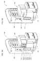
- FIG. 5Ais a rear perspective view of the patient monitor of FIG. 4 connected to a docking station, and in which a sensor module is connected to a docking region of the patient monitor in a first orientation.
- FIG. 5Bis a rear perspective view of the patient monitor of FIG. 5A in which a sensor module is connected to the patient monitor in a second orientation.
- a variety of types of equipmentmay be utilized in hospitals and other medical facilities to acquire, analyze, and display data from sensors attached to a patient.
- the datamay include, for example, pulse, temperature, respiration, blood pressure, blood oxygen, electrocardiogram, and other patient parameters. It is often desirable to continuously monitor patient parameters when transporting patients. When a patient is moved (e.g., the patient is transferred from one hospital ward to another), patient monitoring equipment may also be transported.
- an electrocardiogram (ECG) sensormay be attached to a patient who enters a hospital at an emergency room.
- the ECG sensormay be attached to a module that is configured to receive measured information from the sensor and translate the information into an electronic representation.
- the modulemay in turn be connected to a patient monitor, which may display the information collected by the sensor.
- the patient monitor and related equipmentmay travel with the patient. For example, the patient may travel to a radiology ward and a cardiology ward before being discharged.
- the patient monitor and related equipmentwhich may have initially been located in the emergency room, may now be located in the cardiology ward.
- the foregoing exampleillustrates only one of many possible scenarios in which equipment is moved from one location to another in a hospital. Further, the task of locating a particular piece of equipment (e.g., to perform required maintenance or calibration), even if the general location of the equipment is known (e.g., the equipment remains in a particular ward in a hospital), may be time consuming.
- a tracking systemmay help to ensure that equipment is properly accounted for (e.g., to ensure that equipment does not go missing), is properly configured, and is properly utilized.
- the practice of manually tracking the movement of equipment and implementing processes to ensure that equipment is returned to a particular ward in a hospital or other medical facilitymay be inefficient and cumbersome.
- the systems and methods disclosed hereinmay be employed to track the location of equipment that is connectable to a network, to identify equipment that requires calibration, to identify equipment that is expired, and/or to identify equipment that is malfunctioning.
- the systems and methods disclosed hereinmay be employed in connection with a wide variety of medical devices that are connectable to an electronic network.
- a variety of patient monitors, modules, cables, and sensorsmay be connected in various ways to an electronic network.
- Each device to be trackedmay include a unique device identifier, which may be transmitted to a server via a device identification subsystem when the device is connected to the network.
- the unique device identifier and a system for determining the location of each of a plurality of network connection pointsthe location of each device may be tracked as the medical device interacts with the network.
- such systemsmay also include other functionality configured to ensure that the medical device has not expired, to determine when a medical device requires calibration, or when a medical device should be returned to some other location.
- Embodimentsmay include various steps, which may be embodied in machine-executable instructions to be executed by a general-purpose or special-purpose computer (or other electronic device). Alternatively, the steps may be performed by hardware components that include specific logic for performing the steps or by a combination of hardware, software, and/or firmware.
- Embodimentsmay also be provided as a computer program product including a machine-readable medium having stored thereon instructions that may be used to program a computer (or other electronic device) to perform the processes described herein.
- the machine-readable mediummay include, but is not limited to, hard drives, floppy diskettes, optical disks, CD-ROMs, DVD-ROMs, ROMs, RAMs, EPROMs, EEPROMs, magnetic or optical cards, solid-state memory devices, or other types of computer-readable media suitable for storing electronic instructions.
- FIG. 1illustrates a simplified functional block diagram of one embodiment of a system 100 for determining the location of a medical device in a hospital or other medical facility.
- system 100may be configured for tracking docking stations 132 , 137 , patient monitors 140 , 172 , sensor modules 160 , 167 , and sensor 165 .
- the locations of other types of devices, or a plurality of types of devicesmay also be tracked.
- cables for patient monitoringas described in co-pending U.S. patent application Ser. No. 12/432,558, which is incorporated herein by reference, could be tracked.
- Each piece of equipment to be trackedis associated with a unique identifier 136 , 151 , 161 , 166 , that identifies each piece of equipment within system 100 .
- System 100includes a plurality of network connections 190 , 191 , 192 , 193 .
- network connections 190 , 191 , 192 , 193may each be associated with a particular location (e.g., a particular room in a hospital, a particular area, such as a supply closet, etc.).
- System 100includes a plurality of docking stations 132 , 137 connected to respective network connections 190 , 192 .
- the location of docking stations 132 , 137may be determined based on the location associated with the network connection to which each docking station is connected. For example, the locations of docking stations 132 , 137 may correspond to a particular room or department within a hospital.
- Patient monitors 140 , 172may be mobile, and may allow patients to be continuously monitored in transit without requiring that a patient be disconnected from a respective patient monitor 140 , 172 . Accordingly, in certain embodiments, the patient monitors 140 , 172 may each be configured to selectively couple with and selectively decouple from any of a plurality of docking stations (e.g., 132 , 137 ).
- a plurality of docking stationse.g., 132 , 137 .
- patient monitor 140is shown as being coupled to docking station 132 .
- Docking station 132provides patient monitor 140 with power and/or a connection to a network 130 , such as a hospital's local area network (LAN) and/or the Internet.
- Docking station 132is illustrated as including a power interface 134 and a network interface 135 .
- Power interface 134may be configured to convert an alternating current (AC) power signal to a direct current (DC) power signal and/or provide power signal conditioning for patient monitor 140 .
- Network interface 135may include, for example, an Ethernet communication controller to allow the coupled patient monitor 140 to communicate through network 130 through docking station 132 .
- Network interface 134may be associated with a media access control (MAC) address.
- MACmedia access control
- the MAC address of network interface 135may be the same as unique identifier 136 . It is contemplated that other types of identifiers may be utilized, including but not limited to serial numbers or arbitrarily assigned identifiers.
- docking station 132may also include a memory device 133 .
- the memory device 133may include non-volatile random access memory (RAM) that provides addressable storage and may be used in certain embodiments to store configuration settings and/or other types of data.
- RAMnon-volatile random access memory
- memory device 133stores a unique identifier 136 associated with docking station 132 .
- the patient monitor 140includes a processor 141 , a display device 142 , a memory 143 , a radio frequency identifier (RFID) tag 144 , a user interface 147 , a sensor module interface 148 , a parameter module 149 , a communication device 150 , a unique identifier 151 , and a diagnostic unit 145 .
- processor 141is configured to process patient data signals received through sensor module interface 148 and to display the patient data signals (e.g., as waveforms and/or numerical readouts) on the display device 142 .
- Sensor module interface 148may be connected to a sensor module 160 , which may in turn be connected to a sensor 165 .
- Sensor module interface 148may be configured to process the acquired patient data signals in cooperation with the processor 141 .
- Patient monitor 140may store the patient data signals in memory 143 along with other data.
- patient monitor 140may store a default set of configuration settings in memory 143 .
- configuration settingsmay be adjusted based on a location of patient monitor 140 .
- the configuration settings required for a patient monitor 140 in an emergency roommay differ from the settings required for a patient monitor 140 in an operating room.
- the default set of configuration settingsmay be selected based on the location of patient monitor 140 .
- the communication device 150may be configured to communicate with network 130 through the network interface 135 of the docking station 132 .
- Communication device 150may be embodied using a wide variety of wired and wireless communication technologies, such as Ethernet, 802.11x, Ultra-wide band, Bluetooth, Zigbee, and the like.
- patient monitor 140includes an RFID tag 144 , which may be interrogated by RFID transceiver 199 .
- RFID transceiver 199may be connected to network 130 by way of a network connection 193 .
- RFID tag 144may contain an integrated circuit known as an RFID transponder, which is connected to a small coupling coil.
- RFID transceiver 199contains a coupling coil, connected to suitable electronics. In operation, the coil of RFID tag 144 is brought near the coil of RFID transceiver 199 . The coil of RFID transceiver 199 excites the coil within RFID tag 144 . In response to this excitement by RFID transceiver 199 , RFID tag 144 may emit a radio frequency signal, which may correspond to a digital data stream.
- the digital data streammay correspond to unique identifier 151 .
- the emitted radio frequency signalmay be received by RFID transceiver 199 , and unique identifier 151 may be passed via network 130 to server 110 .
- Various manufacturesproduce commercially available RFID devices that may embody RFID tag 144 and RFID transceiver 199 .
- an RFID tagmay also be placed on sensor modules, sensors, and/or other types of equipment, to help locate equipment that may not be currently in use.
- sensor module 167is not connected to network 130 .
- the usermay employ RFID transceiver 199 to query RFID tag 164 of sensor module 167 . In this way, the location of sensor module 167 may be determined.
- RFID transceiver 199RFID tag 164 may be selectively activated and wirelessly connected to network 130 even though sensor module 167 may not be in use.
- patient monitor 140may comprise a diagnostic unit 145 .
- Diagnostic unit 145may be configured to perform a self-diagnostic test on patient monitor 140 , sensor module 160 , and/or sensor 165 . Diagnostic unit 145 may be configured, for example, to read various voltages within patient monitor 140 or to determine other conditions. The results of a self-diagnostic test may be evaluated by diagnostic unit 145 , or the results of the self-diagnostic test may be forwarded to server 110 via network 130 for evaluation.
- Sensor module 160may be configured to selectively couple with and decouple from the patient monitor 140 .
- the coupling between sensor module 160 and patient monitor 140can be mechanical, electrical, optical, and/or of any other suitable variety.
- the couplingcan be for physical union, communication, and/or power transfer.
- Sensor module 160may be configured to interface a particular type of sensor (e.g., a CO 2 sensor, an ECG sensor) with patient monitor 140 .
- Sensor module 160may include electronic components that translate the input of a particular type of sensor into a more generic electronic format that can be utilized by patient monitor 140 . In this way patient monitor 140 may interface with a wide variety of sensors.
- Sensor module 160may include a processor 162 and a memory 163 .
- Processor 162 and memory 163may allow sensor module 160 to process information received from sensor 165 and prepare the information for use by patient monitor 140 .
- a patient monitormay not require a sensor module in order to connect to a sensor. As illustrated in FIG. 1 , for example, patient monitor 172 is connected directly with sensor 174 .
- Sensor 165may be configured to sense a variety of types of data, including a patient's pulse, temperature, respiration, blood pressure, blood oxygen, electrocardiogram, and other patient parameters. Sensor 165 may be selectively coupled with sensor module 160 . In certain embodiments, the sensor 165 may include an RFID tag for remote identification and/or data communication.
- patient monitor 140may transmit unique identifier 151 to server 110 .
- the transmission of unique identifier 151 and subsequent identification of patient monitor 140may be accomplished by a device identification subsystem.
- the device identification subsystemmay comprise a network operable to transmit unique identifier 151 together with the necessary components in server 110 (e.g., a processor 111 and appropriate data structure stored in a memory 113 ) to associate unique identifier 151 with patient monitor 140 .
- Server 110may be connected to network 130 via a network interface 112 .
- Server 110comprises processor 111 and memory 113 .
- a data bus 123may provide a communication link between processor 111 and memory 113 .
- Processor 111may operate using any number of processing rates, architectures, and may be implemented using a general purpose or application specific processor. Processor 111 may be configured to perform various algorithms and calculations described herein. Processor 111 may be embodied as a general purpose integrated circuit, an application specific integrated circuit, a field-programmable gate array, and other programmable logic devices.
- the illustrated modules(reference nos. 114 , 115 , 116 , 118 , 119 , 120 , and 122 ) are executable by the processor.
- Memory 113may be implemented using a variety of computer-readable storage media, including hard drives, RAM, solid-state memory devices, and other storage media suitable for storing electronic instructions and other data. Certain embodiments may be provided as a computer program product including a computer-readable storage medium having stored instructions thereon that may be used to program a computer (or other electronic device) to perform processes described herein.
- FIG. 1illustrates various software modules located in memory 113
- the functions associated with the various software modulesmay be performed in other ways.
- various subsystemsmay be employed that utilize application specific integrated circuits or other hardware implementations to perform the described functions.
- Embodiments employing a combination of both hardware and software configured to perform the functionality of the various modulesare also contemplated.
- the functions of various modules illustrated in FIG. 1may be distributed throughout system 100 . Alternate embodiments may also include additional servers, which may operate as a distributed architecture.
- a location subsystem 114may be configured to associate the location of a plurality of network connections (e.g., network connects 190 , 191 , 192 , 193 ) within a facility.
- location subsystem 114may be programmed with the location of each wired connection. For example, each room in a hospital may be wired with a network interface. The location of each network interface may be recorded, and when a medical device is connected, the location of the medical device may be determined based on the location of the network connection to which it is connected.
- wireless technologiessuch as IEEE 802.11, Bluetooth, Zigbee, and RFID.
- a medical deviceconnects to a wireless transceiver (e.g., docking station 137 connecting to network 130 via wireless connection 192 , or patient monitor 172 connecting to network 130 via wireless connection 191 )
- the location of the medical devicemay be approximated using the location of the wireless transceiver.
- refinements to the approximationare also contemplated, including but not limited to triangulation using multiple wireless transceivers, determination of signal strength, and other techniques in order to more accurately determine a location of a medical device connected wirelessly to a network.
- the function of storing a location of each of the plurality of network connection pointsmay be performed by a location subsystem.
- a mapping subsystem 115may be configured to display a location of a particular device within a facility.
- Mapping subsystem 115may store a representation of the facility in which system 100 is employed. The representation of the facility, together with the information contained in location subsystem 114 may be utilized to generate a graphical representation of a location of a medical device on a map. Displaying the location graphically on a map, may assist users in locating a desired device.
- mapping subsystem 115may be configured to display an estimate of the area in which a desired device is located.
- a notification subsystem 116may be configured to provide notification upon the occurrence of a specified condition.
- a variety of conditionsmay prompt a notification.
- the conditions that prompt a notificationmay be user-customizable.
- notification subsystem 116may provide notification when a particular piece of equipment assigned to a first area in a hospital is removed from the first are or used for a specified amount of time in a second area of the hospital. In this way users of the equipment may be made aware of the fact that the piece of equipment should be returned to the first area.
- Notification subsystem 116may also provide notification based on other criteria, including a notification that a particular device requires calibration, or that a particular device has expired (exceeded its useful life).
- Notification subsystem 116may provide notification in a variety of ways, including, but not limited to, displaying a message on display 142 , playing an audible message, placing a telephone call with a pre-recorded message, and/or sending an email, SMS, instant message, page, or other electronic message to a specified recipient.
- the function of generating a notification when a specified condition is satisfiedmay be performed by a notification subsystem.
- Web interface subsystem 119may be configured to allow access to information stored in memory 113 via a web interface.
- the web interfacemay allow for access to information stored in memory 113 via an internal network, or intranet, or may allow for access from a wide-area network, such as the Internet.
- Diagnostic subsystem 120may be configured to interact with devices in system 100 to ensure that the medical devices are operating according to specified conditions.
- diagnostic unit 145 in patient monitor 140may be able to perform self-diagnostic tests, or may perform diagnostic tests on sensor module 160 and/or sensor 165 .
- the results of these diagnostic testsmay be transmitted via network 130 to sever 110 , where the results may be evaluated by diagnostic subsystem 120 .
- certain diagnostic criteriamay be stored in device tracking subsystem 118 .
- the results of the diagnostic testsmay be compared against the values stored in device tracking subsystem 118 .
- Diagnostic subsystem 120may be configured to prompt a user to take action when conditions of a medical device fall outside of specified parameters. For example, a nurse may be prompted to check sensor 165 and/or sensor module 160 when voltage readings from the sensor are outside of a certain range. Diagnostic subsystem 120 may also be configured to track instances of malfunction in order to identify equipment that may perform unreliably.
- Calibration subsystem 122may be configured to interact with devices in system 100 to ensure that the medical devices are calibrated on an appropriate schedule.
- sensor module 160may require calibration after some amount of cumulative use (e.g., 100 hours).
- System 100may be configured to track the time that sensor module 160 is in use, and provide a notification when sensor module 160 is due for calibration.
- device tracking subsystem 118may be configured to track the cumulative time a particular sensor module is used.
- sensor module 160may comprise a processor 162 and a memory 163 . Processor 162 and memory 163 may be configured to determine an amount of time that sensor module 160 is in use and the requirements for calibration. When calibration is required, sensor module 160 may notify a user of the need for configuration.
- sensor module 160may communicate the need for configuration to server 110 , and notification subsystem 116 may alert a specified user of the need for calibration.
- the function of associating a medical device with calibration information and evaluating when the medical device requires calibration based on the calibration informationmay be performed by a calibration subsystem.
- Query subsystem 117may be configured to allow a user to query devices attached to network 130 and identify devices that satisfy a specified criteria. For example, a user may enter a query to locate a CO 2 module. In response to the query, system 100 may transmit the query to devices connected to network 130 and display a result indicating the location of each CO 2 module and the status of each module (e.g. whether the module is in use or not in use). In other embodiments, query subsystem 117 may be configured to interact with device tracking subsystem 118 , which may be configured to maintain the location and status of various devices. Query subsystem 117 may also be configured to identify devices that are not connected to network 130 at the time of the query and to display the last known location of such devices that satisfy the specified criteria. The function of querying devices connected to network 130 to determine which devices satisfy a specified criteria may be performed by a device querying subsystem.
- Device tracking subsystem 118may be a repository for a variety of information regarding various devices to be tracked by system 100 .
- Device tracking subsystem 118may be configured to track a variety of types of equipment and a variety of types of information about each piece of equipment.
- Device tracking subsystem 118may be queried by other modules or components in system 100 .
- the function of storing a variety of information regarding various devices to be trackedmay be performed by a device tracking subsystem.
- FIG. 2illustrates one exemplary data structure for device tracking subsystem 118 .
- table 200includes an ID or MAC address column 201 to associate each piece of equipment with a MAC address or other device specific identifier.
- Other types of data tracked by device tracking subsystem 118may include device type 202 , a calibration date 203 , owner information 204 , expiration information 205 , diagnostic information 206 , a last known location 207 , and a date last used 208 .
- Each type of datamay be collected and utilized to add features to system 100 ( FIG. 1 ).
- the calibration date 203may be utilized to determine when a particular device requires calibration. When calibration is required, a user may receive a notification and may then perform the required calibration.
- expiration information 205may also be tracked, and may permit the identification of expired equipment. Owner information 204 may also be tracked. Tracking such information may be desirable when a particular piece of equipment may be transported to other areas in a facility. In certain embodiments, a notification may be issued when a piece of equipment is utilized outside of a designated area. Expiration information 205 may be tracked to indicate when a particular piece of equipment will expire. Diagnostic information 206 may include information regarding certain criteria that can be measured in order to ensure that a particular device is operating within a prescribed range. A last known location 207 may be useful in locating devices that are not currently in use.
- a search for that itemmay be expedited by initiating the search in the location where the item was last used.
- the last used 208 informationmay also be utilized to help locate items by indicating which items are currently in use, and how long it has been since an item has been used.
- FIG. 3illustrates a flow chart of one embodiment of a method 300 for locating a medical device.
- the medical devicetransmits 310 a unique identifier of the medical device to a server.
- the servermay query 330 a device tracking subsystem for information using the unique identifier.
- the servermay also determine 340 a location of the network connection associated with the medical device.
- the method 300may then update 350 the location and other device specific information.
- the device specific informationmay include calibration information, expiration information, diagnostic information, the date the medical device was last used, and the like. If appropriate, any notifications associated with the medical device may be displayed 360 .
- FIG. 4is a perspective view of a patient monitor according to one embodiment.
- System 400includes a patient monitor 140 , a sensor module 160 , and a docking station 132 .
- Patient monitor 140can be configured to selectively couple with and decouple from docking station 132
- sensor module 160can be configured to selectively couple with and decouple from patient monitor 140 .
- Patient monitor 140may include one or more gripping regions 410 , 412 that are configured to aid in coupling and decoupling patient monitor 140 from docking station 132 .
- a medical practitioner 414can firmly grasp with his or her hands 416 , 418 gripping regions 410 , 412 during removal of patient monitor 140 from docking station 132 .
- patient monitor 140is illustrated as having been removed from docking station 132 .
- a front surface of patient monitor 140can include a display 142 that is configured to display information in a visually perceivable format.
- Screen 142may be of any suitable variety, including those presently known and those yet to be devised.
- screen 142may include a liquid crystal display (LCD) panel.
- LCDliquid crystal display
- screen 142may be configured to receive information or otherwise interact with a medical practitioner.
- screen 142may include a touch screen.
- Patient monitor 140may include one or more ports for receiving or delivering information, which can include one or more serial ports, USB ports, Ethernet ports, DVI ports, or any other suitable variety of ports, interfaces, or connectors.
- patient monitor 140may include wireless connections (not illustrated), such as 802.11, UWB, Zigbee, Bluetooth, and the like.
- information received via one or more of the portscan be displayed on the screen 142 .
- At least a portion of the information displayed by patient monitor 140may represent information received from a patient or that otherwise relates to a patient.
- one or more sensorsare connected to the patient to sense a particular parameter, and information obtained via the one or more sensors is delivered to the sensor module 160 .
- the sensorsmay deliver information to sensor module 160 via one or more cables (not shown) connected to one or more ports.
- Sensor module 160may be configured to process the information it receives from a sensor and deliver it to patient monitor 140 , which can display the processed information.
- patient monitor 140may further process the information prior to displaying it.
- Patient monitor 140may also display information that is independent of the patient, such as, for example, a notification regarding the configuration of patient monitor 140 , or the need to calibrate sensor module 160 .
- Docking station 132may be mounted in a substantially fixed position.
- docking station 132may be fixedly mounted to a wall within a hospital room in a single position by one or more plates, brackets, screws, bolts, or other mounting hardware and attachment devices.
- docking station 132may be configured to transition among multiple fixed positions.
- docking station 132is coupled to a mounting strip 422 , which is in turn mounted to a wall (not shown) of a hospital room.
- Docking station 132is capable of being adjusted upwardly or downwardly along a path constrained by one or more channels defined by mounting strip 422 so as to transition among a variety of positions. In each such position, docking station 132 can be fixed relative to mounting strip 422 .
- docking station 132is coupled with mounting strip 422 via a mounting plate or a mounting bracket (not shown), the position of which can be adjusted upwardly or downwardly within the channels in any suitable manner.
- FIG. 5Aillustrates an embodiment of a patient monitor 140 connected to a docking station 132 , and in which a sensor module 160 is connected to a docking region 520 of the patient monitor 140 .
- Sensor module 160includes a plurality of connectors or ports 522 a , 522 b , 522 c , 522 d , 522 e , 522 f , which can be configured to couple with one or more wires or cables (not shown).
- the cablescan extend between ports 522 and one or more sensors (not shown), which can be configured to gather data regarding a patient (not shown).
- Patient monitor 140can be configured to be mounted in a substantially fixed position, and sensor module 160 can be configured to transition from a first orientation relative to patient monitor 140 ( FIG. 5A ) to a second orientation relative to patient monitor 140 ( FIG. 5B ) without moving patient monitor 140 or docking station 132 from the substantially fixed position.
- sensor module 160can be conveniently manipulated to allow for cables to be run to one side 510 of patient monitor 140 or the other side.
- ports 522are moved from one side 510 of patient monitor 140 to an opposite side of patient monitor 140 .
- ports 522are not visible in the view depicted in FIG. 5B .
Landscapes
- Engineering & Computer Science (AREA)
- Health & Medical Sciences (AREA)
- General Health & Medical Sciences (AREA)
- Biomedical Technology (AREA)
- Medical Informatics (AREA)
- General Business, Economics & Management (AREA)
- Epidemiology (AREA)
- Business, Economics & Management (AREA)
- Primary Health Care (AREA)
- Public Health (AREA)
- Computer Networks & Wireless Communication (AREA)
- Signal Processing (AREA)
- Computing Systems (AREA)
- Measuring And Recording Apparatus For Diagnosis (AREA)
Abstract
Description
Claims (29)
Priority Applications (2)
| Application Number | Priority Date | Filing Date | Title |
|---|---|---|---|
| US12/645,327US8334768B2 (en) | 2009-12-22 | 2009-12-22 | Systems and methods for determining a location of a medical device |
| CN201010600680.2ACN102104625B (en) | 2009-12-22 | 2010-12-22 | Systems and methods for determining a location of a medical device |
Applications Claiming Priority (1)
| Application Number | Priority Date | Filing Date | Title |
|---|---|---|---|
| US12/645,327US8334768B2 (en) | 2009-12-22 | 2009-12-22 | Systems and methods for determining a location of a medical device |
Publications (2)
| Publication Number | Publication Date |
|---|---|
| US20110148624A1 US20110148624A1 (en) | 2011-06-23 |
| US8334768B2true US8334768B2 (en) | 2012-12-18 |
Family
ID=44150233
Family Applications (1)
| Application Number | Title | Priority Date | Filing Date |
|---|---|---|---|
| US12/645,327Active2031-06-03US8334768B2 (en) | 2009-12-22 | 2009-12-22 | Systems and methods for determining a location of a medical device |
Country Status (2)
| Country | Link |
|---|---|
| US (1) | US8334768B2 (en) |
| CN (1) | CN102104625B (en) |
Cited By (37)
| Publication number | Priority date | Publication date | Assignee | Title |
|---|---|---|---|---|
| US8737048B2 (en)* | 2009-08-25 | 2014-05-27 | Mindray Ds Usa, Inc. | Modules for monitoring patients and related systems and methods |
| US20140229385A1 (en)* | 2013-02-08 | 2014-08-14 | Schlage Lock Company Llc | Control system and method |
| US20140379255A1 (en)* | 2013-06-19 | 2014-12-25 | Zoll Medical Corporation | Systems and methods of determining location using a medical device |
| US9333290B2 (en) | 2006-11-13 | 2016-05-10 | Q-Core Medical Ltd. | Anti-free flow mechanism |
| US9404490B2 (en) | 2004-11-24 | 2016-08-02 | Q-Core Medical Ltd. | Finger-type peristaltic pump |
| US9457158B2 (en) | 2010-04-12 | 2016-10-04 | Q-Core Medical Ltd. | Air trap for intravenous pump |
| US9581152B2 (en) | 2006-11-13 | 2017-02-28 | Q-Core Medical Ltd. | Magnetically balanced finger-type peristaltic pump |
| US9657902B2 (en) | 2004-11-24 | 2017-05-23 | Q-Core Medical Ltd. | Peristaltic infusion pump with locking mechanism |
| US9674811B2 (en) | 2011-01-16 | 2017-06-06 | Q-Core Medical Ltd. | Methods, apparatus and systems for medical device communication, control and localization |
| US20170199797A1 (en)* | 2016-01-08 | 2017-07-13 | Zoll Medical Corporation | Patient assurance system and method |
| US9726167B2 (en) | 2011-06-27 | 2017-08-08 | Q-Core Medical Ltd. | Methods, circuits, devices, apparatuses, encasements and systems for identifying if a medical infusion system is decalibrated |
| US9855110B2 (en) | 2013-02-05 | 2018-01-02 | Q-Core Medical Ltd. | Methods, apparatus and systems for operating a medical device including an accelerometer |
| US10113543B2 (en) | 2006-11-13 | 2018-10-30 | Q-Core Medical Ltd. | Finger type peristaltic pump comprising a ribbed anvil |
| US10155118B2 (en) | 2013-08-01 | 2018-12-18 | Zoll Medical Corporation | Systems and methods for utilizing identification devices in a wearable medical therapy device |
| US10376169B2 (en) | 2015-03-24 | 2019-08-13 | Zoll Medical Corporation | Systems and methods of determining location using a medical device |
| US10600512B1 (en) | 2019-08-18 | 2020-03-24 | Medigate tech Ltd. | Network-based calculation of prevalence of repeated medical imaging |
| US10610624B2 (en) | 2013-03-14 | 2020-04-07 | Smith & Nephew, Inc. | Reduced pressure therapy blockage detection |
| US10639502B2 (en) | 2010-10-12 | 2020-05-05 | Smith & Nephew, Inc. | Medical device |
| US10658079B1 (en) | 2019-08-18 | 2020-05-19 | Medigate tech Ltd. | Crowd-based recommendations of a version of firmware for medical devices |
| US10825566B1 (en) | 2019-08-18 | 2020-11-03 | Medigate tech Ltd. | Ensuring availability of medical devices to receive maintenance |
| US11056232B2 (en) | 2019-08-18 | 2021-07-06 | Medigate tech Ltd. | Medication usage auditing based on analysis of infusion pump network traffic |
| US11141062B2 (en) | 2018-12-10 | 2021-10-12 | Geissler Companies, Llc | System and method for animal location tracking and health monitoring using long range RFID and temperature monitoring |
| US11202569B2 (en) | 2016-03-31 | 2021-12-21 | Zoll Medical Corporation | Remote access for ambulatory medical device |
| US11213211B2 (en) | 2015-03-20 | 2022-01-04 | Zoll Medical Corporation | Systems and methods for testing a medical device |
| US11315681B2 (en) | 2015-10-07 | 2022-04-26 | Smith & Nephew, Inc. | Reduced pressure therapy device operation and authorization monitoring |
| US11369730B2 (en) | 2016-09-29 | 2022-06-28 | Smith & Nephew, Inc. | Construction and protection of components in negative pressure wound therapy systems |
| US11602461B2 (en) | 2016-05-13 | 2023-03-14 | Smith & Nephew, Inc. | Automatic wound coupling detection in negative pressure wound therapy systems |
| US11679189B2 (en) | 2019-11-18 | 2023-06-20 | Eitan Medical Ltd. | Fast test for medical pump |
| US11712508B2 (en) | 2017-07-10 | 2023-08-01 | Smith & Nephew, Inc. | Systems and methods for directly interacting with communications module of wound therapy apparatus |
| US11793924B2 (en) | 2018-12-19 | 2023-10-24 | T.J.Smith And Nephew, Limited | Systems and methods for delivering prescribed wound therapy |
| US11865352B2 (en) | 2020-09-30 | 2024-01-09 | Zoll Medical Corporation | Remote monitoring devices and related methods and systems with audible AED signal listening |
| US11974903B2 (en) | 2017-03-07 | 2024-05-07 | Smith & Nephew, Inc. | Reduced pressure therapy systems and methods including an antenna |
| US12002566B2 (en) | 2013-03-14 | 2024-06-04 | Smith & Nephew, Inc. | Attachment system for mounting apparatus |
| US12090264B2 (en) | 2012-05-22 | 2024-09-17 | Smith & Nephew Plc | Apparatuses and methods for wound therapy |
| US12133789B2 (en) | 2014-07-31 | 2024-11-05 | Smith & Nephew, Inc. | Reduced pressure therapy apparatus construction and control |
| US12263294B2 (en) | 2016-09-28 | 2025-04-01 | T.J.Smith And Nephew, Limited | Systems and methods for operating negative pressure wound therapy devices |
| US12370300B2 (en) | 2019-08-15 | 2025-07-29 | T.J.Smith And Nephew, Limited | Systems and methods for monitoring essential performance of wound therapy |
Families Citing this family (40)
| Publication number | Priority date | Publication date | Assignee | Title |
|---|---|---|---|---|
| US9596989B2 (en) | 2009-03-12 | 2017-03-21 | Raytheon Company | Networked symbiotic edge user infrastructure |
| US8610562B2 (en)* | 2010-02-01 | 2013-12-17 | Welch Allyn, Inc. | Automatic determination of location for ethernet devices |
| US9035766B2 (en)* | 2010-07-07 | 2015-05-19 | Honeywell International Inc. | System and method of determining gas detector information and status via RFID tags |
| US20120238301A1 (en)* | 2010-07-22 | 2012-09-20 | Shipsin Llc | Systems and methods for networked radio systems and coordinated broadcasting |
| US20120089369A1 (en)* | 2010-10-07 | 2012-04-12 | Patrick Abuzeni | Medical sensor data manager |
| US8897198B2 (en) | 2011-01-14 | 2014-11-25 | Covidien Lp | Medical device wireless network architectures |
| US8818260B2 (en) | 2011-01-14 | 2014-08-26 | Covidien, LP | Wireless relay module for remote monitoring systems |
| US9020419B2 (en) | 2011-01-14 | 2015-04-28 | Covidien, LP | Wireless relay module for remote monitoring systems having power and medical device proximity monitoring functionality |
| US8811888B2 (en) | 2011-01-14 | 2014-08-19 | Covidien Lp | Wireless relay module for monitoring network status |
| US8855550B2 (en) | 2011-01-14 | 2014-10-07 | Covidien Lp | Wireless relay module having emergency call functionality |
| US8798527B2 (en) | 2011-01-14 | 2014-08-05 | Covidien Lp | Wireless relay module for remote monitoring systems |
| US9495511B2 (en)* | 2011-03-01 | 2016-11-15 | Covidien Lp | Remote monitoring systems and methods for medical devices |
| US8694600B2 (en) | 2011-03-01 | 2014-04-08 | Covidien Lp | Remote monitoring systems for monitoring medical devices via wireless communication networks |
| US8903308B2 (en) | 2011-01-14 | 2014-12-02 | Covidien Lp | System and method for patient identification in a remote monitoring system |
| WO2013075748A1 (en)* | 2011-11-24 | 2013-05-30 | Telefonaktiebolaget L M Ericsson (Publ) | System and method for maintaining location information in a database |
| TWI575995B (en)* | 2012-05-07 | 2017-03-21 | 動聯國際股份有限公司 | Internet of things system |
| US20140025809A1 (en)* | 2012-07-19 | 2014-01-23 | Cepheid | Remote monitoring of medical devices |
| CN104620245A (en) | 2012-09-13 | 2015-05-13 | 柯惠有限合伙公司 | Docking station for enteral feeding pump |
| ITMI20121850A1 (en)* | 2012-10-30 | 2014-05-01 | Kalpa S R L | NETWORK CABLE AND ELECTRONIC SYSTEM FOR THE LOCALIZATION OF AT LEAST ONE ELECTRICAL / ELECTRONIC DEVICE INSIDE AT LEAST ONE BUILDING |
| US8937544B2 (en) | 2012-11-05 | 2015-01-20 | DePuy Synthes Products, LLC | Systems and methods for tagging and tracking surgical devices and surgical accessories using radio frequency identification tags |
| US20140155827A1 (en) | 2012-12-03 | 2014-06-05 | Mylan, Inc. | Medicament information system and method |
| US9643770B2 (en) | 2012-12-03 | 2017-05-09 | Mylan Inc. | System and method for medicament storage, dispensing, and administration |
| US9179260B2 (en) | 2012-12-03 | 2015-11-03 | Mylan Inc. | Medicament information system and method |
| US9692829B2 (en) | 2012-12-03 | 2017-06-27 | Mylan Inc. | Medication delivery system and method |
| WO2014204615A2 (en)* | 2013-05-22 | 2014-12-24 | Neurala, Inc. | Methods and apparatus for iterative nonspecific distributed runtime architecture and its application to cloud intelligence |
| USD746441S1 (en) | 2013-09-13 | 2015-12-29 | Covidien Lp | Pump |
| US20150261986A1 (en)* | 2014-03-14 | 2015-09-17 | Qualcomm Incorporated | Wireless search |
| WO2016023151A1 (en)* | 2014-08-11 | 2016-02-18 | 深圳迈瑞生物医疗电子股份有限公司 | Medical apparatus data transmitting system and method |
| CN104188624B (en)* | 2014-08-15 | 2016-01-20 | 深圳市理邦精密仪器股份有限公司 | A kind of medical menitoring system of automatic identification sensor and method |
| US20160055740A1 (en)* | 2014-08-25 | 2016-02-25 | Mindray Ds Usa, Inc. | Systems and methods for medical device location discovery |
| US10200241B2 (en)* | 2015-05-13 | 2019-02-05 | Stryker Corporation | Method of wireless discovery and networking of medical devices in care environments |
| CZ309010B6 (en) | 2015-06-02 | 2021-11-24 | Linet Spol. S.R.O. | Equipment for determining the parking position of a hospital bed |
| CN104905820B (en)* | 2015-06-09 | 2017-12-19 | 深圳市理邦精密仪器股份有限公司 | A kind of method and apparatus that data are shifted by medical energy converter |
| US10987084B2 (en)* | 2016-06-28 | 2021-04-27 | Carestream Health, Inc. | Ultrasound system and method |
| US10070805B1 (en)* | 2017-03-13 | 2018-09-11 | General Electric Company | Patient monitoring system and method having location-specific contextual alarming |
| CN109756969A (en)* | 2019-01-18 | 2019-05-14 | 西安交通大学医学院第一附属医院 | System and method for dynamic management of visual equipment using ZigBee technology |
| CN112150763B (en)* | 2019-06-27 | 2022-05-24 | 深圳市理邦精密仪器股份有限公司 | User positioning early warning method, medical equipment and user positioning early warning device |
| WO2021188786A1 (en)* | 2020-03-18 | 2021-09-23 | Okeeffe Gregory | Systems and methods for using a sound-producing breathing device to perform breathing exercises, and/or determine pulmonary function |
| WO2021236545A1 (en)* | 2020-05-18 | 2021-11-25 | Medical Informatics Corp. | Auto association of medical devices with location |
| US20250062017A1 (en)* | 2021-12-22 | 2025-02-20 | Gambro Lundia Ab | Medical device interoperability methods, apparatus, and system |
Citations (11)
| Publication number | Priority date | Publication date | Assignee | Title |
|---|---|---|---|---|
| US5265594A (en) | 1990-10-30 | 1993-11-30 | Siemens Aktiengesellschaft | Apparatus for regulating the flow-through amount of a flowing medium |
| US6658118B1 (en) | 1998-06-05 | 2003-12-02 | Dana Corporation | Suppression of fluid-borne noise |
| US20070233521A1 (en)* | 2006-03-28 | 2007-10-04 | Hospira, Inc. | Medication administration and management system and method |
| US20070267940A1 (en) | 2006-05-15 | 2007-11-22 | Par Technologies, Llc. | Compressor and compression using motion amplification |
| US20090120439A1 (en) | 2007-11-08 | 2009-05-14 | Fred Goebel | Method of triggering a ventilator |
| EP2116752A1 (en) | 2008-04-17 | 2009-11-11 | Behr GmbH & Co. KG | Fluid pressure pulsation attenuation device |
| US20100090004A1 (en)* | 2008-10-09 | 2010-04-15 | Sands Daniel L | System and method for inventory management of medical assets |
| US20100121156A1 (en)* | 2007-04-23 | 2010-05-13 | Samsung Electronics Co., Ltd | Remote-medical-diagnosis system method |
| US7941096B2 (en)* | 2009-09-20 | 2011-05-10 | Awarepoint Corporation | Wireless tracking system and method utilizing near-field communication devices |
| US7997474B2 (en)* | 2007-06-21 | 2011-08-16 | General Electric Company | System and method for configuring a medical device |
| US8040238B2 (en)* | 2009-10-08 | 2011-10-18 | Awarepoint Corporation | Wireless tracking system and method for backhaul of information |
- 2009
- 2009-12-22USUS12/645,327patent/US8334768B2/enactiveActive
- 2010
- 2010-12-22CNCN201010600680.2Apatent/CN102104625B/enactiveActive
Patent Citations (14)
| Publication number | Priority date | Publication date | Assignee | Title |
|---|---|---|---|---|
| US5265594A (en) | 1990-10-30 | 1993-11-30 | Siemens Aktiengesellschaft | Apparatus for regulating the flow-through amount of a flowing medium |
| US6658118B1 (en) | 1998-06-05 | 2003-12-02 | Dana Corporation | Suppression of fluid-borne noise |
| US20070233521A1 (en)* | 2006-03-28 | 2007-10-04 | Hospira, Inc. | Medication administration and management system and method |
| US20070233035A1 (en)* | 2006-03-28 | 2007-10-04 | Hospira, Inc. | Medication administration and management system and method |
| US20070233520A1 (en)* | 2006-03-28 | 2007-10-04 | Hospira, Inc. | Medication administration and management system and method |
| US20070267940A1 (en) | 2006-05-15 | 2007-11-22 | Par Technologies, Llc. | Compressor and compression using motion amplification |
| US20100121156A1 (en)* | 2007-04-23 | 2010-05-13 | Samsung Electronics Co., Ltd | Remote-medical-diagnosis system method |
| US7997474B2 (en)* | 2007-06-21 | 2011-08-16 | General Electric Company | System and method for configuring a medical device |
| US20090120439A1 (en) | 2007-11-08 | 2009-05-14 | Fred Goebel | Method of triggering a ventilator |
| EP2116752A1 (en) | 2008-04-17 | 2009-11-11 | Behr GmbH & Co. KG | Fluid pressure pulsation attenuation device |
| US20100090004A1 (en)* | 2008-10-09 | 2010-04-15 | Sands Daniel L | System and method for inventory management of medical assets |
| US7941096B2 (en)* | 2009-09-20 | 2011-05-10 | Awarepoint Corporation | Wireless tracking system and method utilizing near-field communication devices |
| US8040238B2 (en)* | 2009-10-08 | 2011-10-18 | Awarepoint Corporation | Wireless tracking system and method for backhaul of information |
| US8089354B2 (en)* | 2009-10-08 | 2012-01-03 | Awarepoint Corporation | Wireless tracking system and method for backhaul of information |
Cited By (59)
| Publication number | Priority date | Publication date | Assignee | Title |
|---|---|---|---|---|
| US10184615B2 (en) | 2004-11-24 | 2019-01-22 | Q-Core Medical Ltd. | Peristaltic infusion pump with locking mechanism |
| US9657902B2 (en) | 2004-11-24 | 2017-05-23 | Q-Core Medical Ltd. | Peristaltic infusion pump with locking mechanism |
| US9404490B2 (en) | 2004-11-24 | 2016-08-02 | Q-Core Medical Ltd. | Finger-type peristaltic pump |
| US9581152B2 (en) | 2006-11-13 | 2017-02-28 | Q-Core Medical Ltd. | Magnetically balanced finger-type peristaltic pump |
| US9333290B2 (en) | 2006-11-13 | 2016-05-10 | Q-Core Medical Ltd. | Anti-free flow mechanism |
| US10113543B2 (en) | 2006-11-13 | 2018-10-30 | Q-Core Medical Ltd. | Finger type peristaltic pump comprising a ribbed anvil |
| US8737048B2 (en)* | 2009-08-25 | 2014-05-27 | Mindray Ds Usa, Inc. | Modules for monitoring patients and related systems and methods |
| US9457158B2 (en) | 2010-04-12 | 2016-10-04 | Q-Core Medical Ltd. | Air trap for intravenous pump |
| US10639502B2 (en) | 2010-10-12 | 2020-05-05 | Smith & Nephew, Inc. | Medical device |
| US12403331B2 (en) | 2010-10-12 | 2025-09-02 | Smith & Nephew, Inc. | Medical device |
| US11565134B2 (en) | 2010-10-12 | 2023-01-31 | Smith & Nephew, Inc. | Medical device |
| US9674811B2 (en) | 2011-01-16 | 2017-06-06 | Q-Core Medical Ltd. | Methods, apparatus and systems for medical device communication, control and localization |
| US9726167B2 (en) | 2011-06-27 | 2017-08-08 | Q-Core Medical Ltd. | Methods, circuits, devices, apparatuses, encasements and systems for identifying if a medical infusion system is decalibrated |
| US12090264B2 (en) | 2012-05-22 | 2024-09-17 | Smith & Nephew Plc | Apparatuses and methods for wound therapy |
| US9855110B2 (en) | 2013-02-05 | 2018-01-02 | Q-Core Medical Ltd. | Methods, apparatus and systems for operating a medical device including an accelerometer |
| US20140229385A1 (en)* | 2013-02-08 | 2014-08-14 | Schlage Lock Company Llc | Control system and method |
| US11295298B2 (en) | 2013-02-08 | 2022-04-05 | Schlage Lock Company Llc | Control system and method |
| US10037525B2 (en)* | 2013-02-08 | 2018-07-31 | Schlage Lock Company Llc | Control system and method |
| US12002566B2 (en) | 2013-03-14 | 2024-06-04 | Smith & Nephew, Inc. | Attachment system for mounting apparatus |
| US11633533B2 (en) | 2013-03-14 | 2023-04-25 | Smith & Nephew, Inc. | Control architecture for reduced pressure wound therapy apparatus |
| US10610624B2 (en) | 2013-03-14 | 2020-04-07 | Smith & Nephew, Inc. | Reduced pressure therapy blockage detection |
| US10905806B2 (en) | 2013-03-14 | 2021-02-02 | Smith & Nephew, Inc. | Reduced pressure wound therapy control and data communication |
| US10271771B2 (en) | 2013-06-19 | 2019-04-30 | Zoll Medical Corporation | Systems and methods of determining location using a medical device |
| US12220228B2 (en) | 2013-06-19 | 2025-02-11 | Zoll Medical Corporation | Systems and methods of determining location using a medical device |
| US9383451B2 (en)* | 2013-06-19 | 2016-07-05 | Zoll Medical Corporation | Systems and methods of determining location using a medical device |
| US10980444B2 (en) | 2013-06-19 | 2021-04-20 | Zoll Medical Corporation | Systems and methods of determining location using a medical device |
| US11690532B2 (en) | 2013-06-19 | 2023-07-04 | Zoll Medical Corporation | Systems and methods of determining location using a medical device |
| US20140379255A1 (en)* | 2013-06-19 | 2014-12-25 | Zoll Medical Corporation | Systems and methods of determining location using a medical device |
| US10155118B2 (en) | 2013-08-01 | 2018-12-18 | Zoll Medical Corporation | Systems and methods for utilizing identification devices in a wearable medical therapy device |
| US12133789B2 (en) | 2014-07-31 | 2024-11-05 | Smith & Nephew, Inc. | Reduced pressure therapy apparatus construction and control |
| US11213211B2 (en) | 2015-03-20 | 2022-01-04 | Zoll Medical Corporation | Systems and methods for testing a medical device |
| US11701006B2 (en) | 2015-03-20 | 2023-07-18 | Zoll Medical Corporation | Systems and methods for testing a medical device |
| US12251199B2 (en) | 2015-03-20 | 2025-03-18 | Zoll Medical Corporation | Systems and methods for testing a medical device |
| US11191470B2 (en) | 2015-03-24 | 2021-12-07 | Zoll Medical Corporation | Systems and methods of determining location using a medical device |
| US10376169B2 (en) | 2015-03-24 | 2019-08-13 | Zoll Medical Corporation | Systems and methods of determining location using a medical device |
| US11315681B2 (en) | 2015-10-07 | 2022-04-26 | Smith & Nephew, Inc. | Reduced pressure therapy device operation and authorization monitoring |
| US11783943B2 (en) | 2015-10-07 | 2023-10-10 | Smith & Nephew, Inc. | Reduced pressure therapy device operation and authorization monitoring |
| US20170199797A1 (en)* | 2016-01-08 | 2017-07-13 | Zoll Medical Corporation | Patient assurance system and method |
| US11709747B2 (en)* | 2016-01-08 | 2023-07-25 | Zoll Medical Corporation | Patient assurance system and method |
| US11202569B2 (en) | 2016-03-31 | 2021-12-21 | Zoll Medical Corporation | Remote access for ambulatory medical device |
| US12109004B2 (en) | 2016-03-31 | 2024-10-08 | Zoll Medical Corporation | Remote access for ambulatory medical device |
| US11602461B2 (en) | 2016-05-13 | 2023-03-14 | Smith & Nephew, Inc. | Automatic wound coupling detection in negative pressure wound therapy systems |
| US12263294B2 (en) | 2016-09-28 | 2025-04-01 | T.J.Smith And Nephew, Limited | Systems and methods for operating negative pressure wound therapy devices |
| US12420006B2 (en) | 2016-09-29 | 2025-09-23 | Smith & Nephew, Inc. | Construction and protection of components in negative pressure wound therapy systems |
| US11369730B2 (en) | 2016-09-29 | 2022-06-28 | Smith & Nephew, Inc. | Construction and protection of components in negative pressure wound therapy systems |
| US11974903B2 (en) | 2017-03-07 | 2024-05-07 | Smith & Nephew, Inc. | Reduced pressure therapy systems and methods including an antenna |
| US11712508B2 (en) | 2017-07-10 | 2023-08-01 | Smith & Nephew, Inc. | Systems and methods for directly interacting with communications module of wound therapy apparatus |
| US12083262B2 (en) | 2017-07-10 | 2024-09-10 | Smith & Nephew, Inc. | Systems and methods for directly interacting with communications module of wound therapy apparatus |
| US11141062B2 (en) | 2018-12-10 | 2021-10-12 | Geissler Companies, Llc | System and method for animal location tracking and health monitoring using long range RFID and temperature monitoring |
| US11793924B2 (en) | 2018-12-19 | 2023-10-24 | T.J.Smith And Nephew, Limited | Systems and methods for delivering prescribed wound therapy |
| US12268806B2 (en) | 2018-12-19 | 2025-04-08 | T.J.Smith And Nephew, Limited | Systems and methods for delivering prescribed wound therapy |
| US12370300B2 (en) | 2019-08-15 | 2025-07-29 | T.J.Smith And Nephew, Limited | Systems and methods for monitoring essential performance of wound therapy |
| US10658079B1 (en) | 2019-08-18 | 2020-05-19 | Medigate tech Ltd. | Crowd-based recommendations of a version of firmware for medical devices |
| US10825566B1 (en) | 2019-08-18 | 2020-11-03 | Medigate tech Ltd. | Ensuring availability of medical devices to receive maintenance |
| US11056232B2 (en) | 2019-08-18 | 2021-07-06 | Medigate tech Ltd. | Medication usage auditing based on analysis of infusion pump network traffic |
| US10600512B1 (en) | 2019-08-18 | 2020-03-24 | Medigate tech Ltd. | Network-based calculation of prevalence of repeated medical imaging |
| US11679189B2 (en) | 2019-11-18 | 2023-06-20 | Eitan Medical Ltd. | Fast test for medical pump |
| US12357839B2 (en) | 2020-09-30 | 2025-07-15 | Zoll Medical Corporation | Remote monitoring devices and related methods and systems with audible AED signal listening |
| US11865352B2 (en) | 2020-09-30 | 2024-01-09 | Zoll Medical Corporation | Remote monitoring devices and related methods and systems with audible AED signal listening |
Also Published As
| Publication number | Publication date |
|---|---|
| US20110148624A1 (en) | 2011-06-23 |
| CN102104625B (en) | 2015-05-27 |
| CN102104625A (en) | 2011-06-22 |
Similar Documents
| Publication | Publication Date | Title |
|---|---|---|
| US8334768B2 (en) | Systems and methods for determining a location of a medical device | |
| US7316648B2 (en) | Portable patient monitoring system including location identification capability | |
| US8484393B2 (en) | Systems and methods for selecting parameters used in a portable patient monitor | |
| US7839266B2 (en) | System and method for managing point of care assignments | |
| JP5038899B2 (en) | Wireless sensor network and wireless sensor network method | |
| US8082160B2 (en) | System and method for collection and communication of data from multiple patient care devices | |
| US8284059B2 (en) | Inventory monitoring and verification system | |
| JP2003179546A (en) | Method and apparatus for accessing medical resource data | |
| US11657915B2 (en) | System and methods for asset tracking | |
| CN104678315A (en) | Wireless Battery Status Management For Medical Devices | |
| JP2012075854A (en) | Medical telemetry system and medical telemeter | |
| US20190006030A1 (en) | Automated healthcare system | |
| EP4314858A1 (en) | System and method for locating and managing patient support apparatus in a healthcare facility | |
| US12303300B2 (en) | Terminal device, information providing system, and computer program | |
| JP6694727B2 (en) | Subject management system | |
| US8976032B2 (en) | Systems, methods and computer-readable media for identifying an anonymous patient | |
| US20030032446A1 (en) | Programmable asset mount for gathering of medical equipment utilization information | |
| JP6621596B2 (en) | Operating state detection device, medical device management system, and medical information management system | |
| JP2016066188A (en) | Medical system | |
| CN104460565A (en) | Mobile nursing platform with power monitoring and its power monitoring system and method | |
| Gupta et al. | IoT-Based Smart Chair for Healthcare Supporting System | |
| TW201510920A (en) | Nursing cart with power monitoring, power monitoring system and method thereof |
Legal Events
| Date | Code | Title | Description |
|---|---|---|---|
| AS | Assignment | Owner name:MINDRAY DS USA, INC., NEW JERSEY Free format text:ASSIGNMENT OF ASSIGNORS INTEREST;ASSIGNORS:EATON, SCOTT;FIDACARO, JAMES;BALJI, JACK;REEL/FRAME:023690/0909 Effective date:20091216 | |
| STCF | Information on status: patent grant | Free format text:PATENTED CASE | |
| AS | Assignment | Owner name:SHENZHEN MINDRAY BIO-MEDICAL ELECTRONICS CO. LTD., CHINA Free format text:ASSIGNMENT OF ASSIGNORS INTEREST;ASSIGNOR:MINDRAY DS USA, INC.;REEL/FRAME:034716/0178 Effective date:20141231 Owner name:SHENZHEN MINDRAY BIO-MEDICAL ELECTRONICS CO. LTD., Free format text:ASSIGNMENT OF ASSIGNORS INTEREST;ASSIGNOR:MINDRAY DS USA, INC.;REEL/FRAME:034716/0178 Effective date:20141231 | |
| FPAY | Fee payment | Year of fee payment:4 | |
| MAFP | Maintenance fee payment | Free format text:PAYMENT OF MAINTENANCE FEE, 8TH YEAR, LARGE ENTITY (ORIGINAL EVENT CODE: M1552); ENTITY STATUS OF PATENT OWNER: LARGE ENTITY Year of fee payment:8 | |
| MAFP | Maintenance fee payment | Free format text:PAYMENT OF MAINTENANCE FEE, 12TH YEAR, LARGE ENTITY (ORIGINAL EVENT CODE: M1553); ENTITY STATUS OF PATENT OWNER: LARGE ENTITY Year of fee payment:12 |