US8333299B2 - Leak resistant drinking cup - Google Patents
Leak resistant drinking cupDownload PDFInfo
- Publication number
- US8333299B2 US8333299B2US12/471,124US47112409AUS8333299B2US 8333299 B2US8333299 B2US 8333299B2US 47112409 AUS47112409 AUS 47112409AUS 8333299 B2US8333299 B2US 8333299B2
- Authority
- US
- United States
- Prior art keywords
- diaphragm
- container
- closure member
- liquid
- leak resistant
- Prior art date
- Legal status (The legal status is an assumption and is not a legal conclusion. Google has not performed a legal analysis and makes no representation as to the accuracy of the status listed.)
- Active, expires
Links
Images


Classifications
- A—HUMAN NECESSITIES
- A47—FURNITURE; DOMESTIC ARTICLES OR APPLIANCES; COFFEE MILLS; SPICE MILLS; SUCTION CLEANERS IN GENERAL
- A47G—HOUSEHOLD OR TABLE EQUIPMENT
- A47G19/00—Table service
- A47G19/22—Drinking vessels or saucers used for table service
- A47G19/2205—Drinking glasses or vessels
- A47G19/2266—Means for facilitating drinking, e.g. for infants or invalids
- A47G19/2272—Means for facilitating drinking, e.g. for infants or invalids from drinking glasses or cups comprising lids or covers
Definitions
- This inventionrelates generally to leak resistant drinking cups and more particularly to a leak resistant drinking cup having a diaphragm that is moveable between a sealed position and an unsealed position.
- Leak resistant drinking cupsare often adapted for use by young children (e.g., infants, toddlers, preschoolers). These types of drinking cups are configured so that when they are turned over, liquid inside the cup is prevented from spilling out of the cup by a valve or valve assembly.
- the cupincludes a container with an open top for receiving and holding liquids therein and a relatively rigid cover for closing the open top of the container.
- a spoutis typically formed as one-piece with the rigid cover for allowing a child to drink from the cup.
- the covercan be releasably attached (e.g., snapped or screwed on) to the container.
- the valve or valve assemblyis typically disposed between the cover and the container and can be moved from a closed, sealing position to an opened, unsealing position to allow liquid to pass out of the cup for drinking.
- the valveis actuated by a vacuum pressure applied by the user to the interior of the cup by sucking on the spout.
- the applied vacuum pressurecauses the valve to move or otherwise deform in such a way (i.e., move toward the spout) that a path past the valve is exposed so liquid can flow out of the cup.
- the valvemight be actuated in other ways, such as a purely mechanical actuation, but for young children vacuum pressure actuation is most preferable because the only time the valve is open is when the child is in the act of taking a drink.
- Vacuum pressure actuated drinking cups of the type just describedhave certain problems generally associated with balancing the need to assure positive sealing with the need to make the cup easy to use for the child.
- a strong seal by the valverequires a relatively large vacuum to open, making it hard for the child to use.
- a valve having a seal that requires a lower vacuum pressure to openmay not seal tightly enough to prevent at least some liquid flowing past it, especially when dropped, swung, shaken, or impacted. Thus, valves having low vacuum pressure actuated seals are typically prone to leak.
- valvesare relatively small and located under the spout. These types of valves often require a substantial vacuum pressure to actuate because the pressure acts on only a relatively small area of the valve. In other words, children will have to suck with significant effort to get the valve to open and obtain a drink, which makes the cup less desirable to the child.
- valve or valve assemblycan be permanently attached to the cover.
- the valve or valve assemblywill become fouled with liquid and particulates in the liquid.
- cleaningis possible, it is very difficult to clean the entire valve/valve assembly or the entire cover. Disassembly of the valve/valve assembly from the cover in this type of configuration would result in destruction of the valve/valve assembly or cover.
- caregiversto provide the child with a drinking cup that has a clean valve/valve assembly and cover in repeated uses of these types of drinking cups.
- valve or valve assemblycan be disassembled from the cover for cleaning. Even with the capability of being disassembled for cleaning, some known valves and valves assemblies are still prone to fouling. Some valves and valve assemblies are difficult to detach and reassemble as they require precise alignment or orientation. Moreover, small valves or pieces of a valve assembly may be easily lost or pose a danger to the child if the cup becomes disassembled.
- a leak resistant drinking cupgenerally comprises a container for receiving and holding a quantity of liquid for drinking.
- the containerhas an open top.
- a lid assemblyis adapted for removable attachment to the container for selectively closing the open top.
- the lid assemblycomprises a liquid discharge member for allowing liquid in the container to exit the cup during drinking.
- a closure memberis adapted for placement adjacent the open top of the container when the lid assembly is attached to the container.
- a flexible diaphragmis moveable between a sealed position in which the diaphragm blocks the flow of liquid from the container to the liquid discharge member, and an unsealed position in which liquid is permitted to flow from the container to the liquid discharge member.
- the diaphragmis moveable from the sealed position to the unsealed portion by a vacuum being applied to the diaphragm by a user sucking on the liquid discharge member.
- the vacuumcauses the diaphragm to flex toward the container and at least in part away from the closure member and thereby move the diaphragm from the sealed position to the unsealed position.
- a leak resistant drinking cupgenerally comprises a container for receiving and holding a quantity of liquid for drinking.
- the containerhas an open top.
- a lid assemblyis adapted for removable attachment to the container for selectively closing the open top.
- the lid assemblycomprises a liquid discharge member for allowing liquid in the container to exit the cup during drinking.
- a flexible diaphragmis moveable between a sealed position in which the diaphragm blocks the flow of liquid from the container to the liquid discharge member, and an unsealed position in which liquid is permitted to flow from the container to the liquid discharge member. The diaphragm is biased toward the sealed position and away from the container.
- a leak resistant drinking cupgenerally comprising a container for receiving and holding a quantity of liquid for drinking.
- the containerhas an open top.
- a lid assemblyis adapted for removable attachment to the container for selectively closing the open top.
- the lid assemblycomprises a liquid discharge member for allowing liquid in the container to exit the cup during drinking.
- a closure memberis adapted for placement adjacent the open top of the container when the lid assembly is attached to the container.
- a flexible diaphragmis moveable between a sealed position in which the diaphragm blocks the flow of liquid from the container to the liquid discharge member, and an unsealed position in which liquid is permitted to flow from the container to the liquid discharge member. The diaphragm is moved toward its sealed position by pressure within the container.
- FIG. 1is a perspective of one embodiment of a leak resistant drinking cup.
- FIG. 2is an exploded perspective of the cup.
- FIG. 3is a side elevation of the cup with a lid removed therefrom.
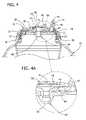
- FIG. 4is an enlarged, fragmentary vertical cross-section of the cup illustrating a diaphragm thereof in a sealed position.
- FIG. 4Ais an enlargement of the encircled portion of FIG. 4 .
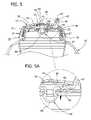
- FIG. 5is an enlarged, fragmentary vertical cross-section of the cup illustrating a portion of the diaphragm being deflected downward but still in its sealed position.
- FIG. 5Ais an enlargement of the encircled portion of FIG. 5 .
- FIG. 6is an enlarged, fragmentary vertical cross-section similar to FIG. 4 but illustrating the diaphragm in an unsealed position.
- FIG. 6Ais an enlargement of the encircled portion of FIG. 6 .
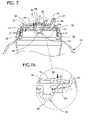
- FIG. 7is an enlarged, fragmentary vertical cross-section of the cup illustrating a diaphragm thereof returned to the sealed position from the unsealed position and a portion deflected downward.
- FIG. 7Ais an enlargement of the encircled portion of FIG. 7 .
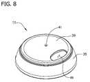
- FIG. 8is a perspective of a cover of the cup.
- FIG. 9is a side elevation of the cover.
- FIG. 10is a top plan of the cover.
- FIG. 11is a bottom plan of the cover.
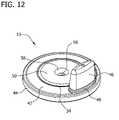
- FIG. 12is a perspective of the diaphragm.
- FIG. 13is a side elevation of the diaphragm.
- FIG. 14is a top plan of the diaphragm.
- FIG. 15is a bottom plan of the diaphragm.
- FIG. 16is a perspective of a closure member.
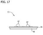
- FIG. 17is a side elevation of the closure member.
- FIG. 18is a top plan of the closure member.
- FIG. 19is a bottom plan of the closure member.
- FIG. 20is a perspective of another embodiment of a cover of the cup.
- FIG. 21is a bottom perspective of another embodiment of a closure member of the cup.
- FIG. 22is a vertical cross-section of the cup having the cover of FIG. 20 and the closure member of FIG. 21 .
- FIG. 23is a vertical cross-section of the cup having a non-rigid container.
- FIG. 24is a vertical cross-section of a leak resistant drinking cup in the form of a sports bottle.
- FIG. 25is a vertical cross-section of a leak resistant drinking cup in the form of a commuter cup.
- FIG. 26is a vertical cross-section of another embodiment of a leak resistant drinking cup, the cup being seen in a tilted, drinking position.
- FIG. 27is a vertical cross-section of yet another embodiment of a leak resistant drinking cup, the cup being seen in a tilted, drinking position.
- FIG. 28is a vertical cross-section of still yet another embodiment of a leak resistant drinking cup, the cup having a longitudinally extending fluid guide.
- FIG. 29is a vertical cross-section of another embodiment of a leak resistant drinking cup, the cup having a transverse extending fluid guide.
- FIG. 30is a vertical cross-section of an embodiment of a leak resistant drinking appliance being operatively connected to a source of liquid.
- a leak resistant drinking cupgenerally indicated at 1
- the illustrated container 3is generally cylindrical and symmetric about a central axis.
- the container 3has a closed bottom 5 , an open top 7 , and a generally cylindrical side wall 6 extending between the closed bottom and the open top.
- the cylindrical side wall 6includes a base portion 8 , a top portion 10 , and a concaved middle portion 12 extending between the base and top portions.
- the middle portion 12 of the side wall 6 of the illustrated container 3is concaved to facilitate grasping of the container and thereby the cup 1 .
- the middle portion 12can be convex or generally straight.
- the base portion 8 of the side wall 6includes a plurality of circumferentially spaced-apart nubs 14 .
- the top portion 10 of the side wall 6has a circular upper edge 21 , an attachment collar 23 disposed beneath and adjacent to the upper edge, and a shoulder 25 disposed below the attachment collar.
- the attachment collar 23has external threads 27 thereon.
- the illustrated container 3has a liquid chamber adapted to hold a quantity of liquid for consumption by a user, such as a small child. More specifically, the illustrated container 3 is adapted to hold approximately 6 ounces of liquid. It is to be understood, however, that the cup 1 can be sized to hold other quantities of liquid (e.g., 9 ounces, 12 ounces, 20 ounces, etc.). For example, the container 3 can be adapted for older children or adults and hold larger quantities of liquid. It is also understood that the container 3 can have a different configuration than the one illustrated herein, such as a sports bottle, a drink tumbler, a commuter cup, etc.
- the container 3can be made of any suitable material such as, without limitation, polypropylene, aluminum, or stainless steel.
- the container 3can also be made in any desired color or colors, and may be transparent, translucent, or opaque.
- the container 3can be rigid as illustrated in FIGS. 1-3 or non-rigid as illustrated in FIG. 23 .
- the lid assembly 9 of the cup 1is adapted for removable attachment to the container 3 for selectively closing the open top 7 of the container.
- the lid assembly 9as illustrated in FIG. 2 , comprises a cover 11 , a closure member 13 , and a diaphragm 15 disposed between the cover and the closure member (each of the lid assembly components being indicated generally by their respective reference numbers).
- the diaphragm 15is operable to block the flow of liquid from the container 3 to prevent liquid from being spilled when the cup 1 is tipped over.
- the diaphragm 15can be deflected, flexed, or otherwise moved by an application of vacuum pressure applied by a user drinking from the cup to permit liquid in the container 3 to flow past the diaphragm and out of the cup.
- the cover 11 , closure member 13 , and diaphragmcan be made of any suitable materials.
- the cover 11 and closure member 13for example, can be made of polypropylene and the diaphragm 15 can be made of silicone.
- the cover 11 , closure member 13 and diaphragm 15can be made in any desired color or colors, and may be transparent, translucent, or opaque.
- the illustrated cup 1also includes a cap, indicated generally at 17 , that is removeably securable to the cover 11 via a snap-fit connection.
- the cap 17can be selectively placed on the cover 11 during periods of non-use (e.g., storage, travel) of the cup 1 , as illustrated in FIG. 1 , and removed during periods of use.
- the cap 17is removed from the cup 1 in FIG. 3 .
- the cap 17can be made of any suitable material, such as polypropylene, and can be made in any desired color or colors, and may be transparent (as illustrated), translucent, or opaque. It is understood that the cap 17 can be omitted from the cup 1 .
- the illustrated cup 1includes a handle assembly, indicated generally at 19 .
- the handle assembly 19has an annular hub 18 and a pair of grips 20 extending outward and downward from the ring.
- the annular hub 18is sized and shaped for engaging the shoulder 25 of the container 3 .
- the grips 20 of the handle assembly 19are adapted for grasping by the user of the cup. It is contemplated that the handle assembly can include a single grip or can be omitted from the cup altogether. It is also contemplated that the handle assembly can be formed integral with the container 3 .
- the cover 11 of the lid assembly 9includes a domed, upper portion 39 and a peripheral skirt 35 depending from the upper portion.
- the upper portion 39includes a relatively small, generally circular aperture 41 in its center and a relatively larger generally oblong or elliptical opening 49 spaced from the central aperture and adjacent the peripheral skirt 35 .
- the cover 11has an inner socket 36 with internal threads 37 for releasably mating with the external threads 27 of the attachment collar 23 of the container 3 .
- the inner socket 36is spaced transversely inward from the peripheral skirt 35 .
- the cover 11also includes an interior rib 38 extending downward from an inner surface of the domed, upper portion 39 .
- the interior rib 38defines the outer boundary of a recess 40 formed in the interior surface of the domed, upper portion 39 of the cover 11 .
- the diaphragm 15has a roughly disk-shaped portion 42 , an annular rim 44 depending from the disk-shaped portion, and a spout 46 (broadly, a “liquid discharge member”) projecting up from the disk-shaped portion adjacent the annular rim.
- the spout 46is sized and shaped for projecting up through the elliptical opening 49 in the cover 11 when the cover and diaphragm 15 are assembled.
- the spout 46includes a circumscribing rib 48 for cooperating with a part of the disk-shaped portion 42 of the diaphragm 15 to capture a portion of the cover 11 adjacent the elliptical opening 49 therein (see, e.g., FIG.
- the spout 46includes a passageway 47 and an opening 45 for allowing liquid to exit or discharge the drinking cup 1 . It is understood that the liquid discharge member can be other than a spout, e.g., an elliptical opening similar to the elliptical opening 49 in the cover 11 .
- the tubular stem 62 and the tip 64collectively defining a sealing member of the diaphragm 15 .
- the tip 64includes a hollow dome 66 and is sized in cross-section larger than the stem 62 to form an annular shoulder 68 adjacent the stem.
- the hollow dome 66 of the tip 64can include a slit to provide a one-way valve to relieve (e.g., vent) excessive vacuum inside the container 3 .
- the annular rim 44depends from the lower surface 52 of the diaphragm 15 and includes a generally planar ring-shaped upper member 70 , a vertical wall member 72 extending downward from the upper member, and a lower member 74 extending inward from the vertical wall member and spaced from the upper member.
- the upper member 70 , vertical wall member 72 , and lower member 74cooperatively define a channel 76 , which is illustrated in FIG. 4 .
- the diaphragm 15is formed as one-piece but it is contemplated that any part, including the tip 64 , the disk-shaped portion 42 , the annular rim 44 , the spout 46 , and/or portions thereof can be formed as separate pieces.
- the closure member 13 of the lid assembly 9comprises an upper base member 80 , a lower base member 82 , and a tapered member 84 extending between the upper and lower base members.
- the tapered member 84slopes from the upper base member 80 to the lower base member 82 .
- the upper base member 80has a mounting band 85 extending about the circumference of the upper base member.
- the mounting band 85extends above and below the upper base member 80 . In other words, the mounting band 85 has a height that is greater than the thickness of the upper base member 80 .
- An annular rib 86is spaced inward from the mounting band 85 and extends downward from the upper base member 80 .
- annular rib 86can be omitted. It is also contemplated that the closure member 13 can be generally flat with the upper and lower base members 80 , 82 being generally in the same plane and the tapered member 84 being omitted.
- a plurality of spaced, elongate upper protuberances 87are disposed on the upper base member 80 adjacent the tapered member 84 .
- the illustrated embodimentincludes eight upper protuberances 87 but it is understood that more or fewer upper protuberances can be provided.
- the lower base member 82includes a central opening 88 and a plurality of spaced, elongate lower protuberances 89 disposed adjacent the central opening.
- the illustrated embodimentincludes four lower protuberances 89 but it is understood that more or fewer lower protuberances can be provided. It is contemplated that protuberances can be provided on the diaphragm 15 instead of or in addition to the upper and lower protuberances 87 , 89 provided on the closure member 13 .
- the illustrated drinking cup 1can be repeatedly taken apart for thorough cleaning and reassembled for the next use.
- the separable components(as seen in FIG. 2 ) are all relatively large so that they are easy to handle, are not easily lost, and do not pose a danger to small children.
- the number of separable componentsis minimized to make assembly and reassembly of the cup 1 relatively easy without comprising the ability to clean each of the components.
- the cap 17can be easily removed from or secured to the drinking cup 1 via its snap-fit connection with the cover 11 .
- the cover 11in the illustrated embodiment, can be removed from or secured to the container 3 via its threaded connection therewith.
- the internal threads 37 of the inner socket 36 of the cover 11can be engaged with and disengaged from the external threads 27 on the attachment collar 23 of the container 3 .
- Other forms and structures for making a releasable connection between the cover 11 and the container 3may be used.
- the cover 11may have a snap-fit connection with the container 3 .
- the closure member 13 , diaphragm 15 , and handle assembly 19are captured between the cover 11 and the container 3 when the cover is screwed onto (or otherwise attached to) the container.
- all of the components of the cup 1can be easily separated, cleaned and reassembled.
- the diaphragm 15can be snapped onto and off of the closure member 13 . More particularly, the diaphragm 15 can be releasably coupled to the closure member 13 by inserting the mounting band 85 of the closure member into the channel 76 of the diaphragm and inserting the mushroom-shaped tip 64 through the central opening 88 in the closure member.
- the lower member 74 of the annular rim 44 of the diaphragm 15 sealingbears against the upper edge 21 of the container 3 when then the cover is screwed onto the container.
- the spout 46 of the diaphragm 15extends up through the elliptical opening 49 in the cover 11 .
- the circumscribing rib 48 extending circumferentially about the spout 46cooperates with part of the disk-shaped portion 42 to capture a portion of the cover 11 that is adjacent the opening 49 .
- the interior rib 38 of the cover 11is received in the tapered groove 54 of the diaphragm 15 .
- first interior chamber 92(broadly, a “vent chamber”). More specifically, the recess 40 in the domed, upper portion 39 of the cover 11 , the upper surface 50 of the disk-shaped portion 42 of the diaphragm 15 , the tubular stem 62 , and the hollow dome 66 of the tip 64 cooperate to define the first interior chamber 92 .
- the first interior chamber 92is in fluid communication with the aperture 41 in the cover 11 and therefore is maintained generally at atmospheric pressure.
- a second interior chamber 94(broadly, a “vacuum chamber”) is defined between the closure member 13 and the diaphragm 15 .
- the lower surface 52 and recessed center 60 of the diaphragm 15 and the lower base member 82 and tapered member 84 of the closure member 13cooperatively define the second interior chamber 94 .
- a portion of the diaphragm 15is in contact with the upper base member 80 of closure member 13 to minimize the volume of the second interior chamber 94 . This facilitates faster priming of the cup 1 during use by minimizing the amount of air that needs to be removed from the second interior chamber 94 before the diaphragm is moved to its unsealed position and thereby allows liquid flow to begin.
- FIGS. 4-7Ait is easy for a small child to get a drink out of the drinking cup 1 by placing her lips around the spout 46 so as to form a seal with the spout, tilting the cup so that liquid in the container 3 flows into contact with the lid assembly, and sucking on the spout. Sucking on the spout 46 removes some of the air from the second interior chamber 94 of the cup 1 , vacuum is thus drawn on the second interior chamber 94 , causing the diaphragm 15 to move from a sealed position ( FIGS. 4 and 4A ) to an unsealed position ( FIGS. 6 and 6A ).
- the vacuumcauses the upper surface 50 of the disk-shaped portion 42 of the diaphragm 15 to flex downward relative to the closure member 13 thereby decreasing the volume of the second interior chamber 94 from a first volume ( FIGS. 4 and 4A ) to a second, lesser volume ( FIGS. 5 and 5A ).
- the upper protuberances 87 of the closure member 13act as a fulcrum about which the diaphragm 15 flexes.
- the upper protuberances 87also act in cooperation with the interior rib 38 of the cover 11 to define a pinch point for capturing a portion of the diaphragm 15 .
- the lower protuberances 89 of the closure memberact as a stop to prevent the diaphragm 15 from engaging and forming a seal with a portion of the closure member about the central opening 88 in the closure member.
- the spacing between each of the upper protuberances 87 and the spacing between each of the lower protuberances 89provide pathways for the liquid within the container 3 to flow.
- the diaphragm 15is more flexible than the closure member 13 .
- the diaphragmis elastomeric and has a durometer of about 75 (type A scale).
- a passageway 96is formed allowing liquid within the container to flow into the second interior chamber 94 of the cup 1 . That is, liquid is permitted to flow past the diaphragm 15 , through the central opening 88 in the closure member 13 , through the second interior chamber 94 and into the spout 46 for drinking.
- the amount of vacuum pressure, which is applied by the user sucking on the spout 46 , needed to move the diaphragm 15 between its sealed and unsealed positionscan be predetermined by varying the area of the diaphragm (i.e., the annular shoulder 68 of the tip 64 ) and the area of the closure member 13 that is contacted by the diaphragm.
- the amount of vacuum pressure needed to move the diaphragm 15 between its sealed and unsealed positionis less than 100 inches of water. In one suitable embodiment, for example, the amount of vacuum pressure needed to move the diaphragm 15 between its sealed and unsealed position is about 47 inches of water.
- the annular shoulder 68 of the tip 64 of the diaphragm 15sealingly engages the portion of the closure member 13 adjacent the central opening 88 therein in a liquid-tight manner. Moreover, the tubular stem 62 and tip 64 of the diaphragm 15 are biased toward the sealed position by the resiliency of the diaphragm 15 .
- the diaphragm 15continues to flex upward (i.e., away from the container 3 ) even after the diaphragm has returned to its sealed position.
- the volume of the second interior chamber 94increases from the second, lesser volume ( FIGS. 7 and 7A ) to the first, greater volume ( FIGS. 4 and 4A ).
- This increase in volume within the second interior chamber 94creates a vacuum pressure that draws any residual liquid away from the opening 45 in the spout 46 .
- the sealing member of the diaphragm 15i.e., the tubular stem 62 and the tip 64 . It is understood, however, that the sealing member can be spaced from and/or oriented orthogonally with respect to the longitudinal axis of the cup 1 without departing from the scope of this invention.
- FIG. 20is a perspective of another embodiment of a cover 111 of the cup 1 .
- the cover 111 illustrated in FIG. 20is similar to the cover 11 of FIGS. 1-19 except that the cover of this embodiment includes a spout shield 151 for covering the spout 46 of the diaphragm 15 .
- the cover 111includes a domed, upper portion 139 and a peripheral skirt 135 depending from the upper portion.
- the upper portion 139includes a relatively small, generally circular aperture 141 in its center.
- the spout shield 151 of this embodimentis sized and shaped for receiving the spout 46 of the diaphragm 15 therein, thereby providing a relatively rigid cover for the relatively soft, flexible spout.
- the circumscribing rib 48 of the spout 46acts as an o-ring in this embodiment by sealingly engaging the interior surface of the spout shield.
- FIG. 21is a bottom perspective of another embodiment of a closure member 113 of the cup 1 .
- the closure member 113 of this embodimentincludes an upper base member 180 , a lower base member 182 , and a tapered member 184 extending between the upper and lower base members.
- the tapered member 184slopes from the upper base member 180 to the lower base member 182 .
- the upper base member 180has a mounting band 185 extending about the circumference of the upper base member.
- the mounting band 185extends above and below the upper base member 180 . In other words, the mounting band 185 has a height that is greater than the thickness of the upper base member 180 .
- An annular rib 186is spaced inward from the mounting band 185 and extends downward from the upper base member 180 . It is contemplated, however, that the annular rib 186 may be omitted.
- a plurality of spaced, elongate upper protuberances(not shown but similar to the upper protuberances 87 of FIG. 16 ) are disposed on the upper base member 180 adjacent the tapered member 184 .
- the lower base member 182includes a central opening 188 and a plurality of spaced, elongate lower protuberances (not shown but similar to the lower protuberances 89 of FIG. 16 ) disposed adjacent the central opening.
- the closure member 113 of this embodimentincludes three grip tabs 195 depending from the lower surface thereof.
- grip tabs 195provide finger grips to facilitate disassembly of the closure member 113 and the diaphragm 15 from the cover 111 .
- the usercan grip one or more of the grip tabs 195 and pull the closure member 113 and diaphragm 15 from engagement with the cover 111 . While three grip tabs 195 are illustrated, more or fewer grip tabs 195 can be provided.
- FIG. 23is a vertical cross-section of the cup 1 illustrating another embodiment of a container, indicated generally at 203 .
- the container 203is at least partially non-rigid and, as a result, can be flexible and/or collapsible.
- the non-rigid container 203can be in the form of a bag (e.g., a foil pouch) or a box (e.g., a juice box). Since the sealed position of diaphragm 15 is in a direction away from the container 203 , squeezing of the non-rigid container 203 causes the pressure within the container to increase and, thereby, creates a greater seal between the diaphragm 15 and the closure member 113 .
- the diaphragm 15has a first sealing pressure in its sealed position and a second, greater sealing pressure when the non-rigid container 203 is squeezed.
- FIG. 24is a vertical cross-section of the cup 1 illustrating yet another embodiment of a container, indicated generally at 303 .
- the container 303is in the form of a sports bottle.
- FIG. 25is a vertical cross-section of the cup 1 illustrating still yet another embodiment of a container, indicated generally at 403 .
- the container 403is in the form of a commuter cup.
- the spout 46 of the diaphragm 15 and the spout shield 151 of the cover 111are shorter than in the previously described embodiments.
- FIG. 26Another embodiment of a leak resistant drinking cup, generally indicated at 501 , is illustrated in FIG. 26 .
- the cup 501is illustrated in a tilted, drinking position.
- the cup 501includes a container, which is generally indicated at 503 , and a generally frustum lid assembly, which is generally indicated at 509 .
- the lid assembly 509 of the cup 501is adapted for removable attachment to the container 503 for selectively closing the container.
- the lid assembly 509comprises a cover 511 , a closure member 513 , and a diaphragm 515 disposed between the cover and the closure member.
- a cap(not shown but similar to the cap 17 seen in FIGS. 1 and 2 ) can be selectively secured to the cover 511 via a snap-fit connection. The cap can be selectively placed on the cover 511 during periods of non-use (e.g., storage, travel) of the cup 501 and removed during periods of use.
- the cover 511 of the lid assembly 509includes an upper portion 539 and a peripheral skirt 535 depending from the upper portion.
- the upper portion 539includes a relatively small, generally circular aperture 541 in its center and a relatively larger generally oblong or elliptical opening 549 spaced from the central aperture.
- the peripheral skirt 535 of the cover 511has internal threads 537 for releasably mating with external threads 527 of the container 503 .
- the cover 511also includes an interior rib 538 extending downward from an inner surface of the upper portion 539 .
- the upper portion 539includes a plateau member 539 a and a sloped member 539 b extending between the plateau and the peripheral skirt 535 .
- the disk-shaped portion 542 of the diaphragm 515has an upper surface 550 and a lower surface 552 .
- the upper surface 550includes an annular tapered groove 554 and the lower surface 552 includes a recessed center 560 that is in fluid communication with the spout 546 .
- a tubular stem 562has a generally mushroom shaped tip 564 that depends from the recessed center 560 of the disk-shaped portion 542 of the diaphragm 515 .
- the tubular stem 562 and the tip 564collectively defining a sealing member of the diaphragm 515 .
- the tip 564includes a hollow dome 566 and is sized in cross-section larger than the stem 562 to form an annular shoulder 568 adjacent the stem.
- the hollow dome 566 of the tip 564include a slit 567 to provide a one-way valve to relieve (e.g., vent) excessive vacuum inside the container 503 .
- the closure member 513 of the lid assembly 509comprises an upper base member 580 , a central opening 588 in the upper base member, and a tapered member 584 extending outward from the upper member.
- the tapered member 584has a mounting band 585 extending about the circumference of the upper base member.
- the diaphragm 515can be releasably coupled to the closure member 513 by joining the mounting band 585 of the closure member to the annular rim 544 of the diaphragm and inserting the mushroom-shaped tip 564 through the central opening 588 in the closure member.
- the annular rim 544 of the diaphragm 515 sealingbears against an upper edge of the container 503 when then the cover 511 is screwed onto the container.
- the spout 546 of the diaphragm 515extends up through the elliptical opening 549 in the cover 511 .
- the interior rib 538 of the cover 511is received in the tapered groove 554 of the diaphragm 515 .
- the cover 511 and diaphragm 515cooperatively define a first interior chamber 592 (broadly, a “vent chamber”) and a second interior chamber 594 (broadly, a “vacuum chamber”) is defined between the closure member 513 and the diaphragm 515 .
- FIG. 27illustrates another embodiment of a leak resistant drinking cup, indicated generally at 601 , having a container 603 and a lid assembly 609 .
- the cup 601is illustrated in a tilted, drinking position.
- the lid assembly 609comprises a cover 611 , a closure member 613 , and a diaphragm 615 disposed between the cover and the closure member.
- the cover 611includes a domed upper portion 639 and a peripheral skirt 635 depending from the upper portion.
- the upper portion 639includes a relatively small, generally circular aperture 641 in its center and a relatively larger generally oblong or elliptical opening 649 spaced from the central aperture.
- the peripheral skirt 635 of the cover 611has internal threads 637 for releasably mating with external threads 627 of the container 603 .
- the diaphragm 615includes a disk-shaped portion 642 , an annular rim 644 , and a spout 646 (broadly, a “liquid discharge member”) projecting outward from the disk-shaped portion.
- the spout 646is sized and shaped for projecting up through the elliptical opening 649 in the cover 611 when the cover and diaphragm 615 are assembled.
- the spout 646includes a passageway 647 and an opening 645 for allowing liquid to exit or discharge the drinking cup 601 .
- the disk-shaped portion 642 of the diaphragm 615has an upper surface 650 and a lower surface 652 .
- the lower surface 652includes a recessed center 660 that is in fluid communication with the spout 646 .
- a tubular stem 662has a generally mushroom shaped tip 664 that depends from the recessed center 660 of the disk-shaped portion 642 of the diaphragm 615 .
- the tubular stem 662 and the tip 664collectively defining a sealing member of the diaphragm 615 .
- the tip 664includes a hollow dome 666 and is sized in cross-section larger than the stem 662 to form an annular shoulder 668 adjacent the stem.
- the hollow dome 666 of the tip 664include a slit 667 to provide a one-way valve to relieve (e.g., vent) excessive vacuum inside the container 603 .
- the closure member 613 of the lid assembly 609comprises a base member 680 having a central opening 688 therethrough.
- the base member 680has a generally planar upper surface 688 a and a sloped lower surface 688 b .
- the lower surface 688 bis sloped toward the central opening 688 in the closure member 613 .
- the base member 680has a mounting band 685 extending about the circumference of the upper base member.
- the diaphragm 615can be releasably coupled to the closure member 613 by joining the mounting band 685 of the closure member to the annular rim 644 of the diaphragm and inserting the mushroom-shaped tip 664 through the central opening 688 in the closure member.
- the annular rim 644 of the diaphragm 615 sealingbears against an upper edge of the container 603 when then the cover 611 is screwed onto the container.
- the spout 646 of the diaphragm 615extends up through the elliptical opening 649 in the cover 611 .
- the cover 611 and diaphragm 615cooperatively define a first interior chamber 692 (broadly, a “vent chamber”) and a second interior chamber 694 (broadly, a “vacuum chamber”) is defined between the closure member 613 and the diaphragm 615 .
- the sloped lower surface 668 a of the base member 688 of the closure member 613directs liquid in the container toward the central opening 688 as illustrated by arrows 691 .
- the sloped lower surface 688 bfunnels the remaining liquid toward the central opening 688 where it can pass through the closure member 613 and into the second interior chamber 694 . From the second interior chamber 694 , the liquid can flow freely into the channel 647 in the spout 646 and out the opening 645 therein for consumption by the child using the cup 601 .
- FIG. 28illustrates another embodiment of a leak resistant drinking cup, indicated generally at 701 , having a container 703 and a lid assembly 709 .
- the lid assembly 709comprises a cover 711 , a closure member 713 , and a diaphragm 715 disposed between the cover and the closure member.
- the illustrated cover 711 and diaphragm 715are substantially the same as the cover 611 and diaphragm 615 illustrated in FIG. 27 and therefore will not be described in detail.
- the closure member 713 of the lid assembly 709comprises a base member 780 having a central opening 788 therethrough.
- the base member 780has a mounting band 785 extending about its circumference.
- a first annular rib 786is spaced inward from the mounting band 785 and extends downward from the base member 780 .
- a second annular rib 793is located between the first annular rib 786 and the central opening 788 .
- the second annular rib 793is disposed generally adjacent the central opening 788 .
- a longitudinally extending fluid guide tube 797is frictionally attached to the second annular rib 793 . During use of the cup 701 , the fluid guide tube 797 directs fluid toward a sealing member of the diaphragm 715 .
- FIG. 29illustrates another embodiment of a leak resistant drinking cup, indicated generally at 801 , having a container 803 and a lid assembly 809 .
- the lid assembly 809comprises a cover 811 , a closure member 813 , and a diaphragm 815 disposed between the cover and the closure member.
- the illustrated cover 811 , closure member 813 , and diaphragm 815are substantially the same as the cover 711 , closure member 713 , and diaphragm 715 illustrated in FIG. 28 and therefore will not be described in detail.
- This embodiment of the cup 801has a transversely extending fluid guide tube 897 that is frictionally attached to the closure member 813 . During use of the cup 801 , the fluid guide tube 897 directs fluid toward a sealing member of the diaphragm 815 .
- FIG. 30illustrates one embodiment of a leak resistant drinking appliance, indicated generally at 901 .
- the drinking appliance 901has a container 903 and a lid assembly 909 .
- the lid assembly 909comprises a cover 911 , a closure member 913 , and a diaphragm 915 disposed between the cover and the closure member.
- the illustrated cover 911 , closure member 913 , and diaphragm 915are substantially the same as the cover 711 , closure member 713 , and diaphragm 715 illustrated in FIG. 28 and therefore will not be described in detail.
- the container 903 of the drinking appliance 901has a bottom 905 , a top 907 , and a generally cylindrical side wall 906 extending between the bottom and the top.
- the cylindrical side wall 906has external threads 927 thereon for mating with internal threads 937 on the cover 911 .
- the bottom 905includes a flange 916 defining a port 922 in fluid communication with the interior space of the container 903 .
- a flexible tubing 924fluidly connects a source of liquid 926 to the container 903 .
- the source of liquid 926provides liquid to the drinking apparatus for consumption by the user.
- the drinking apparatus 901can be used to supply hospital patients with water (or other drinkable liquids).
- the source of liquid 926can be a bag of water hanging from a conventional IV pole.
- the drinking apparatus 901can be used in conjunction with a “beer helmet” or “beer hat” (i.e., headwear adapted to hold one or more containers of beer or other beverage). Liquid can be provided to the drinking apparatus 901 from the source of liquid 926 via gravity or by pressurization of the source of liquid 926 .
Landscapes
- Health & Medical Sciences (AREA)
- General Health & Medical Sciences (AREA)
- Pediatric Medicine (AREA)
- Closures For Containers (AREA)
Abstract
Description
Claims (29)
Priority Applications (10)
| Application Number | Priority Date | Filing Date | Title |
|---|---|---|---|
| US12/471,124US8333299B2 (en) | 2009-05-22 | 2009-05-22 | Leak resistant drinking cup |
| PCT/US2010/035719WO2010135619A1 (en) | 2009-05-22 | 2010-05-21 | Leak resistant drinking cup and diaphragm therefor |
| KR1020117030556AKR20120026099A (en) | 2009-05-22 | 2010-05-21 | Leak resistant drinking cup and diaphragm therefor |
| RU2011151634/12ARU2011151634A (en) | 2009-05-22 | 2010-05-21 | DRINK-RESISTANT DRINKING CUP AND MEMBRANE FOR IT |
| MX2011012319AMX2011012319A (en) | 2009-05-22 | 2010-05-21 | Leak resistant drinking cup and diaphragm therefor. |
| EP10778448AEP2432706A4 (en) | 2009-05-22 | 2010-05-21 | Leak resistant drinking cup and diaphragm therefor |
| CN201080032691.3ACN102459023B (en) | 2009-05-22 | 2010-05-21 | Leak resistant drinking cup and diaphragm therefor |
| CA2761952ACA2761952A1 (en) | 2009-05-22 | 2010-05-21 | Leak resistant drinking cup and diaphragm therefor |
| TW099116397ATW201105276A (en) | 2009-05-22 | 2010-05-21 | Leak resistant drinking cup and diaphragm therefor |
| BRPI1012102ABRPI1012102A2 (en) | 2009-05-22 | 2010-05-21 | leak-resistant drink cup and diaphragm |
Applications Claiming Priority (1)
| Application Number | Priority Date | Filing Date | Title |
|---|---|---|---|
| US12/471,124US8333299B2 (en) | 2009-05-22 | 2009-05-22 | Leak resistant drinking cup |
Publications (2)
| Publication Number | Publication Date |
|---|---|
| US20100294764A1 US20100294764A1 (en) | 2010-11-25 |
| US8333299B2true US8333299B2 (en) | 2012-12-18 |
Family
ID=43123892
Family Applications (1)
| Application Number | Title | Priority Date | Filing Date |
|---|---|---|---|
| US12/471,124Active2031-02-02US8333299B2 (en) | 2009-05-22 | 2009-05-22 | Leak resistant drinking cup |
Country Status (1)
| Country | Link |
|---|---|
| US (1) | US8333299B2 (en) |
Cited By (18)
| Publication number | Priority date | Publication date | Assignee | Title |
|---|---|---|---|---|
| US20110042339A1 (en)* | 2009-08-20 | 2011-02-24 | Medela Holding Ag | Teat unit |
| US20110084084A1 (en)* | 2008-04-07 | 2011-04-14 | Gunnar Berg | Drinking Cup Device |
| USD684426S1 (en)* | 2012-02-28 | 2013-06-18 | Haberman Products Limited | Cup |
| USD698600S1 (en)* | 2013-03-01 | 2014-02-04 | Munchkin, Inc. | Collar with handles |
| US8678228B2 (en)* | 2012-06-28 | 2014-03-25 | Zak Designs, Inc. | Liquid metering assembly |
| WO2015057871A1 (en)* | 2013-10-16 | 2015-04-23 | Munchkin, Inc. | Non-spill drinking container |
| USD730692S1 (en) | 2013-07-24 | 2015-06-02 | Evenflo Feeding Inc. | Sippy cup base |
| US9061813B2 (en) | 2012-06-28 | 2015-06-23 | Zak Designs, Inc. | Liquid metering assembly |
| US9307852B2 (en) | 2013-10-15 | 2016-04-12 | Zak Designs, Inc. | Fluid dispensing valve |
| CN106458390A (en)* | 2014-06-12 | 2017-02-22 | 皇家飞利浦有限公司 | Lid devices for drinking containers |
| WO2017040090A1 (en)* | 2015-09-03 | 2017-03-09 | Helen Of Troy Limited | Drinking cup having an adjustable handle |
| US9650183B2 (en) | 2015-09-03 | 2017-05-16 | Helen Of Troy Limited | Lid assembly and valve for a lid assembly |
| US9771187B2 (en) | 2014-07-25 | 2017-09-26 | Corytus, Llc | Lid and method of using a lid |
| US9782029B1 (en) | 2013-04-30 | 2017-10-10 | Corytus, Llc | Lid and method of using a lid |
| USD904113S1 (en) | 2019-05-10 | 2020-12-08 | Children's Hospital Medical Center | Cup insert |
| US11097876B2 (en) | 2017-01-07 | 2021-08-24 | Rungkarn Chalermwinsuekun | Non-spill drinking container lid device |
| US11937716B2 (en) | 2021-07-09 | 2024-03-26 | Target Brands, Inc. | Sippy cup having a spoutless training lid assembly |
| USD1021563S1 (en) | 2021-07-09 | 2024-04-09 | Target Brands, Inc. | Combined sippy cup and handle base |
Families Citing this family (12)
| Publication number | Priority date | Publication date | Assignee | Title |
|---|---|---|---|---|
| US20110180543A1 (en)* | 2010-01-28 | 2011-07-28 | Rusnak John E | Container Having Adjustable Vented Cover |
| USD675067S1 (en) | 2011-04-15 | 2013-01-29 | Playtex Products, Llc | Container |
| US20130098933A1 (en)* | 2011-04-15 | 2013-04-25 | Maria Alexandra Del Solar | Food container assembly |
| US9895015B2 (en) | 2013-03-15 | 2018-02-20 | No Spill Technologies, LLC | Spill resistant cup with predictable landing positions |
| US10842302B1 (en) | 2013-03-15 | 2020-11-24 | No Spill Technologies, LLC | Spill resistant cup with cooling chamber |
| GB201401497D0 (en) | 2014-01-29 | 2014-03-12 | Jackel Int Ltd | Valve assembly |
| WO2015138885A1 (en)* | 2014-03-14 | 2015-09-17 | No Spill Technologies, LLC | Spill resistant transition cup |
| CN108601468B (en)* | 2015-12-21 | 2020-09-25 | 汉迪-克拉夫特公司 | Valve assembly for a drinking cup and drinking cup with a valve assembly |
| CN113998311B (en)* | 2017-07-18 | 2024-03-15 | 布利克斯有限公司 | Container, container content processor, container content processing system and method |
| USD809857S1 (en)* | 2017-08-31 | 2018-02-13 | John David Porrazzo | Valve handle |
| USD1003111S1 (en)* | 2020-12-08 | 2023-10-31 | Feng Liu | Silicone cup |
| US20250000245A1 (en)* | 2023-06-30 | 2025-01-02 | Vinglace Llc | Drinking vessel with interchangeable handles |
Citations (81)
| Publication number | Priority date | Publication date | Assignee | Title |
|---|---|---|---|---|
| US2442656A (en) | 1946-11-29 | 1948-06-01 | Joseph W Less | Nursing nipple for bottles |
| US3915331A (en) | 1972-12-08 | 1975-10-28 | Bert Russel Chenault | Non-spill cover |
| US4066191A (en)* | 1976-10-18 | 1978-01-03 | Coleman Kenneth L | Drinking and pouring spout for use with easy-opening containers |
| US4135513A (en) | 1975-09-26 | 1979-01-23 | A/S Alto | Drinking nozzle for bottles and similar containers |
| US4623069A (en) | 1984-04-12 | 1986-11-18 | Baxter Travenol Laboratories, Inc. | Nipple and nursing container |
| US4993568A (en) | 1988-12-15 | 1991-02-19 | Jex Co., Ltd. | Nipple for nursing bottles |
| US5071017A (en) | 1991-02-15 | 1991-12-10 | Stuli Iene | Closure cap construction with slitted flexible diaphragm |
| US5079013A (en) | 1990-08-30 | 1992-01-07 | Belanger Richard A | Dripless liquid feeding/training containers |
| US5101992A (en) | 1990-01-12 | 1992-04-07 | Johnson & Johnson Consumer Products, Inc. | Adjustable air inflow for feeding-bottle device |
| US5186347A (en) | 1991-10-15 | 1993-02-16 | Freeman Mark A | Spill-proof closure |
| US5542670A (en) | 1995-07-17 | 1996-08-06 | Playtex Products, Inc. | Flow control element and covered drinking cup |
| US5570796A (en) | 1995-08-04 | 1996-11-05 | Brown; Craig E. | Nursing bottle with an air venting structure |
| US5598809A (en) | 1992-08-12 | 1997-02-04 | Mcinnes; Ross G. | Teat |
| US5667084A (en) | 1994-08-25 | 1997-09-16 | Mother's Love Pte. Ltd. | Liquid flow controlling device |
| US5690679A (en) | 1991-12-30 | 1997-11-25 | Prentiss; John Gilbert | Infant feeding container |
| US5706973A (en) | 1997-01-30 | 1998-01-13 | E. S. Robbins Corporation | Drinking cup and cover with flow control elements |
| US5747083A (en) | 1990-07-20 | 1998-05-05 | Raymond; Jean-Louis | Device of the feeding-bottle type |
| US5779071A (en) | 1995-08-04 | 1998-07-14 | New Vent Designs, Inc. | Nursing bottle with an air venting structure |
| US5791503A (en) | 1996-02-05 | 1998-08-11 | Lyons; Richard A. | Nursing bottle with anti-air ingestion valve |
| US5890620A (en) | 1997-08-14 | 1999-04-06 | Belcastro; Domenic | Automatically sealing cup |
| US5890619A (en) | 1997-05-16 | 1999-04-06 | Belanger; Richard A. | Spill-proof drinking container |
| US5890621A (en) | 1996-10-21 | 1999-04-06 | Gerber Products Company | Cup for young children with cap valved for fluid control |
| US5950857A (en) | 1998-06-17 | 1999-09-14 | Rosen; Jay B. | Leak resistant and squeeze resistant liquid box container |
| US5988425A (en) | 1998-01-19 | 1999-11-23 | Yehl; Gregory | Sipper cup |
| US6037872A (en) | 1998-03-04 | 2000-03-14 | Dunnum; Christopher B. | Baby bottle having removable handles and an automated sound producing means |
| US6050445A (en) | 1998-02-06 | 2000-04-18 | Playtex Products, Inc. | Leak-proof cup assembly with flow control element |
| US6079589A (en) | 1998-03-04 | 2000-06-27 | Nippon Sanso Corporation | Drinking receptacle covers |
| USD429312S (en) | 1999-08-31 | 2000-08-08 | Kimberly-Clark Worldwide, Inc. | Travel filtration bottle |
| US6102244A (en) | 1999-10-20 | 2000-08-15 | The Thermos Company | Mug with multiple sip holes and lid gasket |
| US6102245A (en) | 1992-04-07 | 2000-08-15 | Haberman; Mandy Nicola | Drinking vessel with valve |
| US6116457A (en) | 1995-09-01 | 2000-09-12 | Haberman; Mandy Nicola | Drinks containers |
| USD433729S (en) | 1999-08-31 | 2000-11-14 | Kimberly-Clark Worldwide, Inc. | Filtration bottle with cap |
| US6202877B1 (en) | 1998-10-20 | 2001-03-20 | Playtex Products, Inc. | Lip-openable spill-proof container |
| US6230923B1 (en) | 2000-09-01 | 2001-05-15 | Lineo Baby Merchandise Work's Co., Ltd. | Drinking bottle provided with a flexible liquid-sucking member adapted to serve as a drinking straw |
| US6260731B1 (en) | 1999-09-10 | 2001-07-17 | Tony P. Cummings | Lid and clip combination for child's cup |
| US6269968B1 (en) | 1999-11-18 | 2001-08-07 | Niko Products, Inc. | Valve arrangement for an automatically sealing cup |
| US20010020623A1 (en) | 1999-12-30 | 2001-09-13 | Johnson & Johnson Consumer Companies, Inc. | Elastomeric valve for spill-proof feeding devices |
| USD448242S1 (en) | 1999-12-30 | 2001-09-25 | Johnson & Johnson Consumer Companies, Inc. | Trainer cup |
| USD448976S1 (en) | 1999-12-30 | 2001-10-09 | Johnson & Johnson Consumer Companies, Inc. | Pinched trainer cup |
| US20010027956A1 (en) | 1998-07-15 | 2001-10-11 | Frank Bonacorso | Infant feeding device |
| US6305570B1 (en) | 1998-01-30 | 2001-10-23 | Cannon Rubber Limited, A British Company | Closure assembly for a drinking vessel |
| US20010035420A1 (en) | 2000-03-16 | 2001-11-01 | Michael Fusco | Spill proof training cup |
| USD450535S1 (en) | 1999-12-30 | 2001-11-20 | Mcdonough Justin E. | Trainer cup |
| US6321931B1 (en) | 1997-08-21 | 2001-11-27 | Nouri E. Hakim | No-spill drinking cup apparatus |
| US6325236B1 (en) | 2000-10-16 | 2001-12-04 | Fu Hong Industries Ltd. | Drinking device |
| US6357620B1 (en) | 1997-08-21 | 2002-03-19 | Nouri E. Hakim | No-spill drinking cup apparatus |
| US20020033399A1 (en) | 1998-02-06 | 2002-03-21 | Playtex Products, Inc. | Cup assembly with retaining mechanism |
| US6365202B1 (en) | 1995-08-21 | 2002-04-02 | Frank Ida | Pneumatic squeezable nursing bottle and process of using |
| US20020158075A1 (en) | 2001-03-26 | 2002-10-31 | Caldicott Robert John | One material, one piece spill-proof closure |
| US20020189683A1 (en) | 2001-06-13 | 2002-12-19 | Danby Hal C. | Vacuum demand flow valve |
| US6502418B2 (en) | 2001-02-13 | 2003-01-07 | Insta-Mix, Inc. Subsidiary A | Spill-resistant container with reinforced cold plug |
| US6508379B1 (en) | 1998-11-13 | 2003-01-21 | Henriette Hermine Titia Van De Pol-Klein Nagelvoort | Leak-free drinking cup |
| US6513379B2 (en) | 2000-11-30 | 2003-02-04 | Gerber Products Company | Infant drinking cup |
| US6565743B1 (en) | 1999-08-31 | 2003-05-20 | Kimberly-Clark Worldwide, Inc. | Portable purification container with cumulative use indicator |
| WO2003068036A1 (en) | 2002-02-12 | 2003-08-21 | Baby Björn Ab | A liquid container with suction spout |
| US6609630B1 (en) | 1999-04-22 | 2003-08-26 | Mark A. Freeman | Leak-proof closure apparatus |
| US6629624B2 (en) | 2001-03-05 | 2003-10-07 | Acorn Bay, Llc | Drink spout system |
| US6631832B2 (en) | 1998-03-25 | 2003-10-14 | Crown Cork & Seal Technologies Corporation | Single piece, push-pull dispensing closure and assembly |
| US6631823B2 (en) | 2001-03-05 | 2003-10-14 | Acorn Bay, Llc | Drink spout system |
| US6644510B2 (en) | 2001-06-29 | 2003-11-11 | The Meyer Company | Bag-in-box container and faucet |
| US20030209555A1 (en)* | 2002-05-08 | 2003-11-13 | Niko Products, Inc. | No-spill cover assemly for a drink container |
| US6685042B2 (en) | 1999-02-12 | 2004-02-03 | Robert Dymock McIntyre | Feeder bottles |
| US20040035815A1 (en)* | 2000-09-12 | 2004-02-26 | Webb Ian Alexander | Drinking vessel |
| US20040124170A1 (en) | 2002-12-30 | 2004-07-01 | Joseph Sherrod | Spill proof cap for different sized bottle openings |
| US6758364B1 (en) | 1998-03-18 | 2004-07-06 | Bamed Ag | Container cap for drinking containers having a valve body insert with a deformable sealing lip |
| US6783020B2 (en) | 2002-11-15 | 2004-08-31 | Gerber Products Company | Toddler drinking cup |
| US20040173623A1 (en) | 2003-03-07 | 2004-09-09 | Yuen Yat Keung William | Flow restrictor, a cap with such a flow restrictor, and a drinking cup with such a cap |
| US20040222229A1 (en) | 2003-05-06 | 2004-11-11 | Gabbard Mark E. | Valve for dispensing liquids and method of use |
| US20050045647A1 (en) | 2003-08-27 | 2005-03-03 | Hession John A. | Drinking container |
| US20050072788A1 (en) | 1998-02-06 | 2005-04-07 | Playtex Products, Inc. | Flow control element for use with leak-proof cup assemblies |
| US20050098567A1 (en)* | 1998-02-06 | 2005-05-12 | Playtex Products, Inc. | Cup assembly |
| US20050167438A1 (en) | 2004-02-02 | 2005-08-04 | Max Minyayev | Secure spill-proof configuration for child training cup |
| US20050205589A1 (en) | 2004-03-19 | 2005-09-22 | Davis Dennis L | Sippy cup valve |
| US20060037963A1 (en) | 2004-08-19 | 2006-02-23 | Ramiro Pillado | Cup with a valve for drinking juice |
| US20060169694A1 (en)* | 2005-01-28 | 2006-08-03 | Handi-Craft Company | Leak resistant drinking cup |
| US7108676B2 (en) | 2004-05-04 | 2006-09-19 | Loging James A | Cup for administering medicine to a child |
| US20070138121A1 (en) | 2005-11-16 | 2007-06-21 | The Last Straw, Llc | Drinking devices for children with integrated valve |
| USD555428S1 (en) | 2005-03-11 | 2007-11-20 | Avent Limited | Non-spill cup |
| USD559622S1 (en) | 2006-05-16 | 2008-01-15 | Thermos L.L.C. | Sippy cup |
| WO2008125877A1 (en) | 2007-04-13 | 2008-10-23 | Jackel Trade Marks Pty Limited | Cap for spill-proof beverage container |
| US7556172B2 (en)* | 2006-11-30 | 2009-07-07 | Thermos, L.L.C. | Spill resistant lid assembly for a drink container |
Family Cites Families (1)
| Publication number | Priority date | Publication date | Assignee | Title |
|---|---|---|---|---|
| US579503A (en)* | 1897-03-23 | Car-coupling |
- 2009
- 2009-05-22USUS12/471,124patent/US8333299B2/enactiveActive
Patent Citations (98)
| Publication number | Priority date | Publication date | Assignee | Title |
|---|---|---|---|---|
| US2442656A (en) | 1946-11-29 | 1948-06-01 | Joseph W Less | Nursing nipple for bottles |
| US3915331A (en) | 1972-12-08 | 1975-10-28 | Bert Russel Chenault | Non-spill cover |
| US4135513A (en) | 1975-09-26 | 1979-01-23 | A/S Alto | Drinking nozzle for bottles and similar containers |
| US4066191A (en)* | 1976-10-18 | 1978-01-03 | Coleman Kenneth L | Drinking and pouring spout for use with easy-opening containers |
| US4623069A (en) | 1984-04-12 | 1986-11-18 | Baxter Travenol Laboratories, Inc. | Nipple and nursing container |
| US5101991A (en) | 1988-12-15 | 1992-04-07 | Jex Company, Limited | Nipple for nursing bottle |
| US4993568A (en) | 1988-12-15 | 1991-02-19 | Jex Co., Ltd. | Nipple for nursing bottles |
| US5101992A (en) | 1990-01-12 | 1992-04-07 | Johnson & Johnson Consumer Products, Inc. | Adjustable air inflow for feeding-bottle device |
| US5747083A (en) | 1990-07-20 | 1998-05-05 | Raymond; Jean-Louis | Device of the feeding-bottle type |
| US5079013A (en) | 1990-08-30 | 1992-01-07 | Belanger Richard A | Dripless liquid feeding/training containers |
| US5071017A (en) | 1991-02-15 | 1991-12-10 | Stuli Iene | Closure cap construction with slitted flexible diaphragm |
| US5186347A (en) | 1991-10-15 | 1993-02-16 | Freeman Mark A | Spill-proof closure |
| US5690679A (en) | 1991-12-30 | 1997-11-25 | Prentiss; John Gilbert | Infant feeding container |
| US6102245A (en) | 1992-04-07 | 2000-08-15 | Haberman; Mandy Nicola | Drinking vessel with valve |
| US5598809A (en) | 1992-08-12 | 1997-02-04 | Mcinnes; Ross G. | Teat |
| US5667084A (en) | 1994-08-25 | 1997-09-16 | Mother's Love Pte. Ltd. | Liquid flow controlling device |
| USRE37016E1 (en) | 1995-07-17 | 2001-01-16 | Playtex Products, Inc. | Flow control element and covered drinking cup |
| US5542670A (en) | 1995-07-17 | 1996-08-06 | Playtex Products, Inc. | Flow control element and covered drinking cup |
| US5779071A (en) | 1995-08-04 | 1998-07-14 | New Vent Designs, Inc. | Nursing bottle with an air venting structure |
| US5570796A (en) | 1995-08-04 | 1996-11-05 | Brown; Craig E. | Nursing bottle with an air venting structure |
| US6365202B1 (en) | 1995-08-21 | 2002-04-02 | Frank Ida | Pneumatic squeezable nursing bottle and process of using |
| US6116457A (en) | 1995-09-01 | 2000-09-12 | Haberman; Mandy Nicola | Drinks containers |
| US5791503A (en) | 1996-02-05 | 1998-08-11 | Lyons; Richard A. | Nursing bottle with anti-air ingestion valve |
| US5890621A (en) | 1996-10-21 | 1999-04-06 | Gerber Products Company | Cup for young children with cap valved for fluid control |
| US5706973A (en) | 1997-01-30 | 1998-01-13 | E. S. Robbins Corporation | Drinking cup and cover with flow control elements |
| US5890619A (en) | 1997-05-16 | 1999-04-06 | Belanger; Richard A. | Spill-proof drinking container |
| US5890620A (en) | 1997-08-14 | 1999-04-06 | Belcastro; Domenic | Automatically sealing cup |
| US7243814B2 (en) | 1997-08-21 | 2007-07-17 | Hakim Nouri E | No-spill drinking cup apparatus |
| US6321931B1 (en) | 1997-08-21 | 2001-11-27 | Nouri E. Hakim | No-spill drinking cup apparatus |
| US6357620B1 (en) | 1997-08-21 | 2002-03-19 | Nouri E. Hakim | No-spill drinking cup apparatus |
| US20020179615A1 (en) | 1997-08-21 | 2002-12-05 | Hakim Nouri E. | No-spill drinking cup apparatus |
| US5988425A (en) | 1998-01-19 | 1999-11-23 | Yehl; Gregory | Sipper cup |
| US6305570B1 (en) | 1998-01-30 | 2001-10-23 | Cannon Rubber Limited, A British Company | Closure assembly for a drinking vessel |
| US6050445A (en) | 1998-02-06 | 2000-04-18 | Playtex Products, Inc. | Leak-proof cup assembly with flow control element |
| US20020185495A1 (en) | 1998-02-06 | 2002-12-12 | Playtex Products, Inc. | Leak-proof cup assembly with flow control element |
| US6607092B2 (en) | 1998-02-06 | 2003-08-19 | Playtex Products, Inc. | Cup assembly with retaining mechanism |
| US6422415B1 (en) | 1998-02-06 | 2002-07-23 | Playtex Products, Inc. | Leak-proof cup assembly with flow control element |
| US20050072788A1 (en) | 1998-02-06 | 2005-04-07 | Playtex Products, Inc. | Flow control element for use with leak-proof cup assemblies |
| US20020033399A1 (en) | 1998-02-06 | 2002-03-21 | Playtex Products, Inc. | Cup assembly with retaining mechanism |
| US20050098567A1 (en)* | 1998-02-06 | 2005-05-12 | Playtex Products, Inc. | Cup assembly |
| US20060151499A1 (en) | 1998-02-06 | 2006-07-13 | Playtex Products, Inc. | Flow control element for use with leak-proof cup assemblies |
| US6037872A (en) | 1998-03-04 | 2000-03-14 | Dunnum; Christopher B. | Baby bottle having removable handles and an automated sound producing means |
| US6079589A (en) | 1998-03-04 | 2000-06-27 | Nippon Sanso Corporation | Drinking receptacle covers |
| US6758364B1 (en) | 1998-03-18 | 2004-07-06 | Bamed Ag | Container cap for drinking containers having a valve body insert with a deformable sealing lip |
| US6631832B2 (en) | 1998-03-25 | 2003-10-14 | Crown Cork & Seal Technologies Corporation | Single piece, push-pull dispensing closure and assembly |
| US5950857A (en) | 1998-06-17 | 1999-09-14 | Rosen; Jay B. | Leak resistant and squeeze resistant liquid box container |
| US20010027956A1 (en) | 1998-07-15 | 2001-10-11 | Frank Bonacorso | Infant feeding device |
| US6202877B1 (en) | 1998-10-20 | 2001-03-20 | Playtex Products, Inc. | Lip-openable spill-proof container |
| US6508379B1 (en) | 1998-11-13 | 2003-01-21 | Henriette Hermine Titia Van De Pol-Klein Nagelvoort | Leak-free drinking cup |
| US6685042B2 (en) | 1999-02-12 | 2004-02-03 | Robert Dymock McIntyre | Feeder bottles |
| US6609630B1 (en) | 1999-04-22 | 2003-08-26 | Mark A. Freeman | Leak-proof closure apparatus |
| US6565743B1 (en) | 1999-08-31 | 2003-05-20 | Kimberly-Clark Worldwide, Inc. | Portable purification container with cumulative use indicator |
| USD433729S (en) | 1999-08-31 | 2000-11-14 | Kimberly-Clark Worldwide, Inc. | Filtration bottle with cap |
| USD429312S (en) | 1999-08-31 | 2000-08-08 | Kimberly-Clark Worldwide, Inc. | Travel filtration bottle |
| US6260731B1 (en) | 1999-09-10 | 2001-07-17 | Tony P. Cummings | Lid and clip combination for child's cup |
| US6102244A (en) | 1999-10-20 | 2000-08-15 | The Thermos Company | Mug with multiple sip holes and lid gasket |
| US6786352B2 (en) | 1999-11-18 | 2004-09-07 | Domenic Belcastro | Valve arrangement for an automatically sealing cup |
| US6269968B1 (en) | 1999-11-18 | 2001-08-07 | Niko Products, Inc. | Valve arrangement for an automatically sealing cup |
| US20010020623A1 (en) | 1999-12-30 | 2001-09-13 | Johnson & Johnson Consumer Companies, Inc. | Elastomeric valve for spill-proof feeding devices |
| US20040099674A1 (en) | 1999-12-30 | 2004-05-27 | Mcdonough Justin E. | Elastomeric valve for spill-proof feeding devices |
| USD448242S1 (en) | 1999-12-30 | 2001-09-25 | Johnson & Johnson Consumer Companies, Inc. | Trainer cup |
| USD448976S1 (en) | 1999-12-30 | 2001-10-09 | Johnson & Johnson Consumer Companies, Inc. | Pinched trainer cup |
| USD450535S1 (en) | 1999-12-30 | 2001-11-20 | Mcdonough Justin E. | Trainer cup |
| US6568557B2 (en) | 2000-03-16 | 2003-05-27 | Cosco Management, Inc. | Spill proof training cup |
| US20010035420A1 (en) | 2000-03-16 | 2001-11-01 | Michael Fusco | Spill proof training cup |
| US6230923B1 (en) | 2000-09-01 | 2001-05-15 | Lineo Baby Merchandise Work's Co., Ltd. | Drinking bottle provided with a flexible liquid-sucking member adapted to serve as a drinking straw |
| US20040035815A1 (en)* | 2000-09-12 | 2004-02-26 | Webb Ian Alexander | Drinking vessel |
| USRE38692E1 (en) | 2000-10-16 | 2005-02-01 | Fu Hong Industries Ltd. | Drinking device |
| US6325236B1 (en) | 2000-10-16 | 2001-12-04 | Fu Hong Industries Ltd. | Drinking device |
| US6513379B2 (en) | 2000-11-30 | 2003-02-04 | Gerber Products Company | Infant drinking cup |
| US6502418B2 (en) | 2001-02-13 | 2003-01-07 | Insta-Mix, Inc. Subsidiary A | Spill-resistant container with reinforced cold plug |
| US6631823B2 (en) | 2001-03-05 | 2003-10-14 | Acorn Bay, Llc | Drink spout system |
| US6629624B2 (en) | 2001-03-05 | 2003-10-07 | Acorn Bay, Llc | Drink spout system |
| US20020158075A1 (en) | 2001-03-26 | 2002-10-31 | Caldicott Robert John | One material, one piece spill-proof closure |
| US6554023B2 (en) | 2001-06-13 | 2003-04-29 | Baxter International Inc. | Vacuum demand flow valve |
| WO2002100320A1 (en) | 2001-06-13 | 2002-12-19 | Baxter International Inc. | Vacuum actuated flow valve |
| US20020189683A1 (en) | 2001-06-13 | 2002-12-19 | Danby Hal C. | Vacuum demand flow valve |
| US6863083B2 (en) | 2001-06-13 | 2005-03-08 | Baxter International Inc. | Vacuum demand flow valve |
| US6644510B2 (en) | 2001-06-29 | 2003-11-11 | The Meyer Company | Bag-in-box container and faucet |
| WO2003068036A1 (en) | 2002-02-12 | 2003-08-21 | Baby Björn Ab | A liquid container with suction spout |
| US6732882B2 (en) | 2002-05-08 | 2004-05-11 | Niko Products, Inc. | No-spill cover assemly for a drink container |
| US20030209555A1 (en)* | 2002-05-08 | 2003-11-13 | Niko Products, Inc. | No-spill cover assemly for a drink container |
| US6783020B2 (en) | 2002-11-15 | 2004-08-31 | Gerber Products Company | Toddler drinking cup |
| US20040124170A1 (en) | 2002-12-30 | 2004-07-01 | Joseph Sherrod | Spill proof cap for different sized bottle openings |
| US20040173623A1 (en) | 2003-03-07 | 2004-09-09 | Yuen Yat Keung William | Flow restrictor, a cap with such a flow restrictor, and a drinking cup with such a cap |
| US20040222229A1 (en) | 2003-05-06 | 2004-11-11 | Gabbard Mark E. | Valve for dispensing liquids and method of use |
| US20050045647A1 (en) | 2003-08-27 | 2005-03-03 | Hession John A. | Drinking container |
| US20050167438A1 (en) | 2004-02-02 | 2005-08-04 | Max Minyayev | Secure spill-proof configuration for child training cup |
| US20050205589A1 (en) | 2004-03-19 | 2005-09-22 | Davis Dennis L | Sippy cup valve |
| US7108676B2 (en) | 2004-05-04 | 2006-09-19 | Loging James A | Cup for administering medicine to a child |
| US20060037963A1 (en) | 2004-08-19 | 2006-02-23 | Ramiro Pillado | Cup with a valve for drinking juice |
| US20060169694A1 (en)* | 2005-01-28 | 2006-08-03 | Handi-Craft Company | Leak resistant drinking cup |
| US7575126B2 (en) | 2005-01-28 | 2009-08-18 | Handi-Craft Company | Leak resistant drinking cup |
| USD555428S1 (en) | 2005-03-11 | 2007-11-20 | Avent Limited | Non-spill cup |
| US20070138121A1 (en) | 2005-11-16 | 2007-06-21 | The Last Straw, Llc | Drinking devices for children with integrated valve |
| USD559622S1 (en) | 2006-05-16 | 2008-01-15 | Thermos L.L.C. | Sippy cup |
| US7556172B2 (en)* | 2006-11-30 | 2009-07-07 | Thermos, L.L.C. | Spill resistant lid assembly for a drink container |
| WO2008125877A1 (en) | 2007-04-13 | 2008-10-23 | Jackel Trade Marks Pty Limited | Cap for spill-proof beverage container |
Non-Patent Citations (1)
| Title |
|---|
| International Search Report and Written Opinion from PCT/US/2010/035719 dated Jul. 20, 2010, 6 pages. |
Cited By (26)
| Publication number | Priority date | Publication date | Assignee | Title |
|---|---|---|---|---|
| US20110084084A1 (en)* | 2008-04-07 | 2011-04-14 | Gunnar Berg | Drinking Cup Device |
| US8453870B2 (en)* | 2008-04-07 | 2013-06-04 | Anne May Berg | Drinking cup device |
| US20110042339A1 (en)* | 2009-08-20 | 2011-02-24 | Medela Holding Ag | Teat unit |
| US9168204B2 (en)* | 2009-08-20 | 2015-10-27 | Medela Holding Ag | Teat unit |
| USD684426S1 (en)* | 2012-02-28 | 2013-06-18 | Haberman Products Limited | Cup |
| US8678228B2 (en)* | 2012-06-28 | 2014-03-25 | Zak Designs, Inc. | Liquid metering assembly |
| US9061813B2 (en) | 2012-06-28 | 2015-06-23 | Zak Designs, Inc. | Liquid metering assembly |
| USD698600S1 (en)* | 2013-03-01 | 2014-02-04 | Munchkin, Inc. | Collar with handles |
| US9782029B1 (en) | 2013-04-30 | 2017-10-10 | Corytus, Llc | Lid and method of using a lid |
| USD730692S1 (en) | 2013-07-24 | 2015-06-02 | Evenflo Feeding Inc. | Sippy cup base |
| US9307852B2 (en) | 2013-10-15 | 2016-04-12 | Zak Designs, Inc. | Fluid dispensing valve |
| US9888796B2 (en) | 2013-10-16 | 2018-02-13 | Munchkin, Inc. | Non-spill drinking container |
| US10165878B2 (en) | 2013-10-16 | 2019-01-01 | Munchkin, Inc. | Non-spill drinking container |
| WO2015057871A1 (en)* | 2013-10-16 | 2015-04-23 | Munchkin, Inc. | Non-spill drinking container |
| US9801481B2 (en) | 2013-10-16 | 2017-10-31 | Munchkin, Inc. | Non-spill drinking container |
| US9241588B2 (en) | 2013-10-16 | 2016-01-26 | Munchkin, Inc. | Non-spill drinking container |
| CN106458390B (en)* | 2014-06-12 | 2018-12-07 | 皇家飞利浦有限公司 | Cap assembly for drinking container |
| CN106458390A (en)* | 2014-06-12 | 2017-02-22 | 皇家飞利浦有限公司 | Lid devices for drinking containers |
| US9771187B2 (en) | 2014-07-25 | 2017-09-26 | Corytus, Llc | Lid and method of using a lid |
| US9650183B2 (en) | 2015-09-03 | 2017-05-16 | Helen Of Troy Limited | Lid assembly and valve for a lid assembly |
| WO2017040090A1 (en)* | 2015-09-03 | 2017-03-09 | Helen Of Troy Limited | Drinking cup having an adjustable handle |
| US9993097B2 (en) | 2015-09-03 | 2018-06-12 | Helen Of Troy Limited | Drinking cup having an adjustable handle |
| US11097876B2 (en) | 2017-01-07 | 2021-08-24 | Rungkarn Chalermwinsuekun | Non-spill drinking container lid device |
| USD904113S1 (en) | 2019-05-10 | 2020-12-08 | Children's Hospital Medical Center | Cup insert |
| US11937716B2 (en) | 2021-07-09 | 2024-03-26 | Target Brands, Inc. | Sippy cup having a spoutless training lid assembly |
| USD1021563S1 (en) | 2021-07-09 | 2024-04-09 | Target Brands, Inc. | Combined sippy cup and handle base |
Also Published As
| Publication number | Publication date |
|---|---|
| US20100294764A1 (en) | 2010-11-25 |
Similar Documents
| Publication | Publication Date | Title |
|---|---|---|
| US8333299B2 (en) | Leak resistant drinking cup | |
| US9138088B2 (en) | Leak resistant drinking cup | |
| US7575126B2 (en) | Leak resistant drinking cup | |
| WO2010135619A1 (en) | Leak resistant drinking cup and diaphragm therefor | |
| US10433665B2 (en) | Valve assembly for leak resistant straw cup | |
| US9314120B2 (en) | Cup and lid assembly for a cup | |
| RU2424963C1 (en) | Tight cap for container with drink | |
| US9486392B2 (en) | Infant bottle assembly having a vented nipple | |
| JP2018122936A (en) | Non-spillable drinking container | |
| US8727147B2 (en) | Bottle assembly having bottom vent | |
| US10799046B2 (en) | Valve assembly for a leak resistant drinking cup | |
| US10213034B2 (en) | Valve assembly for a drinking cup and a drinking cup having a valve assembly | |
| KR20200106610A (en) | Leak resistant tumbler for diaphragm therefor |
Legal Events
| Date | Code | Title | Description |
|---|---|---|---|
| AS | Assignment | Owner name:HANDI-CRAFT COMPANY, MISSOURI Free format text:ASSIGNMENT OF ASSIGNORS INTEREST;ASSIGNORS:KEMPER, BERNARD J.;MILLER, CHARLES H.;SIGNING DATES FROM 20090527 TO 20090610;REEL/FRAME:022977/0244 | |
| STCF | Information on status: patent grant | Free format text:PATENTED CASE | |
| AS | Assignment | Owner name:THE NORTHERN TRUST COMPANY, MISSOURI Free format text:SECURITY AGREEMENT;ASSIGNOR:HANDI-CRAFT COMPANY;REEL/FRAME:030048/0906 Effective date:20130319 | |
| FPAY | Fee payment | Year of fee payment:4 | |
| MAFP | Maintenance fee payment | Free format text:PAYMENT OF MAINTENANCE FEE, 8TH YR, SMALL ENTITY (ORIGINAL EVENT CODE: M2552); ENTITY STATUS OF PATENT OWNER: SMALL ENTITY Year of fee payment:8 | |
| AS | Assignment | Owner name:THE NORTHERN TRUST COMPANY, MISSOURI Free format text:SECURITY INTEREST;ASSIGNOR:HANDI-CRAFT COMPANY;REEL/FRAME:062876/0261 Effective date:20220912 | |
| AS | Assignment | Owner name:DR. BROWN'S COMPANY, MISSOURI Free format text:CHANGE OF NAME;ASSIGNOR:HANDI-CRAFT COMPANY;REEL/FRAME:067377/0927 Effective date:20240401 | |
| MAFP | Maintenance fee payment | Free format text:PAYMENT OF MAINTENANCE FEE, 12TH YR, SMALL ENTITY (ORIGINAL EVENT CODE: M2553); ENTITY STATUS OF PATENT OWNER: SMALL ENTITY Year of fee payment:12 | |
| AS | Assignment | Owner name:THE NORTHERN TRUST COMPANY, MISSOURI Free format text:SECURITY INTEREST;ASSIGNOR:DR. BROWN'S COMPANY F/K/A HANDI-CRAFT COMPANY;REEL/FRAME:069270/0072 Effective date:20240401 |