US8333245B2 - Accelerated production of gas from a subterranean zone - Google Patents
Accelerated production of gas from a subterranean zoneDownload PDFInfo
- Publication number
- US8333245B2 US8333245B2US10/246,052US24605202AUS8333245B2US 8333245 B2US8333245 B2US 8333245B2US 24605202 AUS24605202 AUS 24605202AUS 8333245 B2US8333245 B2US 8333245B2
- Authority
- US
- United States
- Prior art keywords
- area
- gas
- production
- water
- well bore
- Prior art date
- Legal status (The legal status is an assumption and is not a legal conclusion. Google has not performed a legal analysis and makes no representation as to the accuracy of the status listed.)
- Expired - Fee Related
Links
- 238000004519manufacturing processMethods0.000titleclaimsabstractdescription254
- 238000000034methodMethods0.000claimsabstractdescription152
- 230000035699permeabilityEffects0.000claimsabstractdescription101
- XLYOFNOQVPJJNP-UHFFFAOYSA-NwaterSubstancesOXLYOFNOQVPJJNP-UHFFFAOYSA-N0.000claimsdescription245
- 239000003245coalSubstances0.000claimsdescription232
- 230000015572biosynthetic processEffects0.000claimsdescription75
- 239000012530fluidSubstances0.000claimsdescription58
- VNWKTOKETHGBQD-UHFFFAOYSA-NmethaneChemical compoundCVNWKTOKETHGBQD-UHFFFAOYSA-N0.000claimsdescription54
- 239000011159matrix materialSubstances0.000claimsdescription25
- 230000007423decreaseEffects0.000claimsdescription24
- 230000005514two-phase flowEffects0.000claimsdescription20
- 239000007789gasSubstances0.000description205
- 238000005755formation reactionMethods0.000description73
- 238000005553drillingMethods0.000description50
- 239000003570airSubstances0.000description28
- 238000010586diagramMethods0.000description20
- 238000005086pumpingMethods0.000description19
- 230000009467reductionEffects0.000description13
- 230000008901benefitEffects0.000description11
- 230000002706hydrostatic effectEffects0.000description10
- 238000005065miningMethods0.000description9
- 238000005520cutting processMethods0.000description6
- 230000001965increasing effectEffects0.000description6
- 238000012360testing methodMethods0.000description6
- 230000000694effectsEffects0.000description5
- 230000004941influxEffects0.000description5
- 238000004891communicationMethods0.000description4
- 230000001186cumulative effectEffects0.000description4
- 230000009977dual effectEffects0.000description4
- 230000008569processEffects0.000description4
- 239000011435rockSubstances0.000description4
- 239000006260foamSubstances0.000description3
- 230000005484gravityEffects0.000description3
- 239000002245particleSubstances0.000description3
- 239000003380propellantSubstances0.000description3
- 229920006395saturated elastomerPolymers0.000description3
- CURLTUGMZLYLDI-UHFFFAOYSA-NCarbon dioxideChemical compoundO=C=OCURLTUGMZLYLDI-UHFFFAOYSA-N0.000description2
- 238000005273aerationMethods0.000description2
- 238000006243chemical reactionMethods0.000description2
- 230000003247decreasing effectEffects0.000description2
- 229910003460diamondInorganic materials0.000description2
- 239000010432diamondSubstances0.000description2
- 230000007613environmental effectEffects0.000description2
- 230000005251gamma rayEffects0.000description2
- 229930195733hydrocarbonNatural products0.000description2
- 150000002430hydrocarbonsChemical class0.000description2
- 239000007788liquidSubstances0.000description2
- 230000007774longtermEffects0.000description2
- 238000012423maintenanceMethods0.000description2
- 238000012986modificationMethods0.000description2
- 230000004048modificationEffects0.000description2
- 230000000737periodic effectEffects0.000description2
- 238000000926separation methodMethods0.000description2
- 230000037380skin damageEffects0.000description2
- 241001051604AppalachiaSpecies0.000description1
- 235000015076Shorea robustaNutrition0.000description1
- 244000166071Shorea robustaSpecies0.000description1
- 230000002411adverseEffects0.000description1
- 239000012080ambient airSubstances0.000description1
- 238000004458analytical methodMethods0.000description1
- RHZUVFJBSILHOK-UHFFFAOYSA-Nanthracen-1-ylmethanolateChemical compoundC1=CC=C2C=C3C(C[O-])=CC=CC3=CC2=C1RHZUVFJBSILHOK-UHFFFAOYSA-N0.000description1
- 239000003830anthraciteSubstances0.000description1
- 239000002802bituminous coalSubstances0.000description1
- 238000007664blowingMethods0.000description1
- 229910002092carbon dioxideInorganic materials0.000description1
- 239000001569carbon dioxideSubstances0.000description1
- 230000008859changeEffects0.000description1
- 238000003776cleavage reactionMethods0.000description1
- 239000003034coal gasSubstances0.000description1
- 238000011109contaminationMethods0.000description1
- 230000036461convulsionEffects0.000description1
- 239000010779crude oilSubstances0.000description1
- 230000006378damageEffects0.000description1
- 238000013461designMethods0.000description1
- 238000011161developmentMethods0.000description1
- 238000009826distributionMethods0.000description1
- 238000005516engineering processMethods0.000description1
- 230000002708enhancing effectEffects0.000description1
- 210000003746featherAnatomy0.000description1
- 239000008398formation waterSubstances0.000description1
- 238000011065in-situ storageMethods0.000description1
- 230000000977initiatory effectEffects0.000description1
- 238000002347injectionMethods0.000description1
- 239000007924injectionSubstances0.000description1
- 239000003077ligniteSubstances0.000description1
- 239000000463materialSubstances0.000description1
- 238000005259measurementMethods0.000description1
- 230000037361pathwayEffects0.000description1
- 239000011148porous materialSubstances0.000description1
- 238000002360preparation methodMethods0.000description1
- 230000001737promoting effectEffects0.000description1
- 238000011084recoveryMethods0.000description1
- 230000007017scissionEffects0.000description1
- 230000035945sensitivityEffects0.000description1
- 230000009919sequestrationEffects0.000description1
- 238000004088simulationMethods0.000description1
- 238000001179sorption measurementMethods0.000description1
- 239000000126substanceSubstances0.000description1
- 238000012876topographyMethods0.000description1
- 210000003462veinAnatomy0.000description1
Images


Classifications
- E—FIXED CONSTRUCTIONS
- E21—EARTH OR ROCK DRILLING; MINING
- E21B—EARTH OR ROCK DRILLING; OBTAINING OIL, GAS, WATER, SOLUBLE OR MELTABLE MATERIALS OR A SLURRY OF MINERALS FROM WELLS
- E21B43/00—Methods or apparatus for obtaining oil, gas, water, soluble or meltable materials or a slurry of minerals from wells
- E21B43/30—Specific pattern of wells, e.g. optimising the spacing of wells
- E21B43/305—Specific pattern of wells, e.g. optimising the spacing of wells comprising at least one inclined or horizontal well
- E—FIXED CONSTRUCTIONS
- E21—EARTH OR ROCK DRILLING; MINING
- E21B—EARTH OR ROCK DRILLING; OBTAINING OIL, GAS, WATER, SOLUBLE OR MELTABLE MATERIALS OR A SLURRY OF MINERALS FROM WELLS
- E21B43/00—Methods or apparatus for obtaining oil, gas, water, soluble or meltable materials or a slurry of minerals from wells
- E21B43/006—Production of coal-bed methane
- E—FIXED CONSTRUCTIONS
- E21—EARTH OR ROCK DRILLING; MINING
- E21B—EARTH OR ROCK DRILLING; OBTAINING OIL, GAS, WATER, SOLUBLE OR MELTABLE MATERIALS OR A SLURRY OF MINERALS FROM WELLS
- E21B43/00—Methods or apparatus for obtaining oil, gas, water, soluble or meltable materials or a slurry of minerals from wells
- E21B43/12—Methods or apparatus for controlling the flow of the obtained fluid to or in wells
- E21B43/121—Lifting well fluids
- E21B43/13—Lifting well fluids specially adapted to dewatering of wells of gas producing reservoirs, e.g. methane producing coal beds
Definitions
- the present inventionrelates generally to the recovery of subterranean resources, and more particularly to a method and system for accelerated production of gas from a subterranean zone.
- Subterranean deposits of coalwhether of “hard” coal such as anthracite or “soft” coal such as lignite or bituminous coal, contain substantial quantities of entrained methane gas. Limited production and use of methane gas from coal deposits has occurred for many years. Substantial obstacles have frustrated more extensive development and use of methane gas deposits in coal seams.
- coal seamsmay extend over large areas, up to several thousand acres, and may vary in depth from a few inches to many feet.
- Coal seamsmay also have a low permeability.
- vertical wells drilled into the coal deposits for obtaining methane gascan generally only drain a fairly small radius of methane gas in low and even medium permeability coal deposits.
- gas in the vicinity of a vertical well boreis produced, further production from the coal seam through the vertical well is limited.
- Another problem in producing methane gas from coal seamsis subterranean water which must be drained from the coal seam in order to produce the methane. As water is removed from the coal seam, it may be replaced with recharge water flowing from other virgin areas of the coal seam and/or adjacent formations. This recharge of the coal seam extends the time required to drain the coal seam and thus prolongs the production time for entrained methane gas which may take five years, ten years, or even longer.
- methane gasmay be produced from the coal seam after a shorter period of water removal. For example, in Appalachia coal beds with a high permeability of ten to fifteen millidarcies have in four or five months been pumped down to the point where gas can be produced.
- the present inventionprovides a method and system for surface production of gas from a subterranean zone that substantially eliminates or reduces the disadvantages and problems associated with previous systems and methods.
- water and gasare produced from a coal seam or other suitable subterranean zone through a horizontal drainage pattern having a plurality of cooperating bores that lower water pressure throughout the drainage area of the pattern to allow accelerated release of gas in the zone.
- a method and system for surface production of gas from a subterranean zoneincludes lowering reservoir pressure in an area of a subterranean zone having a medium to low effective permeability by removing water from the area through a well bore pattern.
- the well bore patterncomprises a multi-branching pattern that provides a drainage network for the area.
- twenty-five percent of the total gas in the area of the subterranean zoneis produced within three years of the start of production.
- the well bore patternmay include a plurality of cooperating bores.
- reservoir pressuremay be substantially and uniformly dropped throughout the area of the subterranean zone by producing water and/or gas through the cooperating bores of the well bore pattern.
- the gasmay also be produced in two-phase flow with the water.
- the gasmay be produced in a self-sustaining flow.
- the well bore patternmay be a pinnate or other omni-directional pattern that intersects a substantial number of natural fractures, which may comprise cleats, of the subterranean zone.
- the patternmay cover a substantially symmetrical area of the subterranean zone.
- the patternsmay be nested to cover a field, formation or other large area.
- the twenty-five percent of gas in the area of the subterranean zonemay be produced within eighteen months, one year, nine months or even six months of the start of water production.
- up to two-thirds of the gas in the area of the subterranean zonemay be produced within five or even three years of the start of production.
- productionmay have a peak with a steep-sloped expediential decline. The peak production rate may occur within months of the start of production with a majority of gas and/or produceable gas in the area being produced prior to a production decline from the peak reaching one-quarter of the peak rate.
- inventionsinclude providing accelerated gas production from subsurface coal, shale and other suitable formations.
- reservoir pressure of a target formationis substantially uniformly reduced across a coverage area to initiate early gas release.
- Gasmay be produced in two-phase flow with entrained water.
- the released gasmay lower the specific gravity and/or viscosity of the produced fluid thereby further accelerating production from the formation.
- the released gasmay act as a propellant for two-phase flow production.
- the pressure reductionmay affect a large rock volume causing a bulk coal or other formation matrix to shrink and further accelerate gas release.
- the attendant increase in cleat widthmay increase formation permeability and may thereby further expedite gas production from the formation.
- Another technical advantage of the present inventionincludes providing a substantially uniform pressure drop across a non-disjointed coverage area of the well bore pattern. As a result, substantially all of the formation in the coverage area is exposed to a drainage point and continuity of the flow unit is enhanced. Thus, trapped zones of unrecovered gas are minimized.
- Still another technical advantage of one or more embodiments of the present inventioninclude providing a well bore pattern with cooperating bores that effectively increase well-bore radius.
- a large surface area of lateral borespromotes high flow rates and minimizes skin damage affects.
- troughs of pressure reduction of the lateral boreseffect a greater area of the formation than a cone of pressure reduction of a vertical bore.
- Still another technical advantage of one or more embodiments of the present inventionincludes providing an omni-directional well bore pattern that may in any horizontal or other suitable orientation intersect a substantial number of natural fractures, which may comprise cleats, of a coal seam or other formation.
- natural fractureswhich may comprise cleats, of a coal seam or other formation.
- water and/or gasmay be produced from a medium to low permeability coal seam despite low relative permeabilities of the formation matrix to water and gas.
- the orientation of the natural fracturesneed not be determined or accounted for in orienting the well bore pattern.
- Still another technical advantage of one or more embodiments of the present inventionincludes maintaining hydraulic seal integrity of a coal or other suitable formation during gas production.
- a pinnate or other substantially uniform patternallows gas production without hydraulic fracturing operations which may fracture seals between the coal and adjacent water bearing sands and cause significant water influx.
- the cooperating borescapture recharge water at the perimeter of the drainage area and provide a shield for the coverage area, trapped cell pressure reduction and continued depleted pressure between the cooperating bores.
- Still another technical advantage of one or more embodiments of the present inventionincludes eliminating the need for large artificial lift devices by providing self-sustaining gas production in a coal, shale or other suitable seam.
- water head pressureis suitably drawn down in the reservoir within a few weeks or months of the start of production allowing high gas flow rates to then lift the water and kick-off the well. Thereafter, a chain reaction sustains gas production and lifts water with the gas.
- Still another technical advantage of one or more embodiments of the present inventionincludes obtaining substantial release of non-near well bore gas within a period of a few weeks of the start of production by blowing down the well at the start of water production.
- compressed airis pumped down a tubing string to gas lift water collected from the subterranean zone at the surface.
- up to five thousand barrels or more of watermay be produced per day from the subterranean zone. This may kick-off the well within one or a couple of weeks, allow a peak production rate under continuous flow conditions to be reached within a period of months and allow the bulk of gas to be produced within one, two or a few years of the start of production.
- Yet another technical advantage of one or more embodiments of the present inventionincludes providing an enhanced and/or accelerated revenue stream for coal bed methane and other suitable gas production.
- accelerated production of gasallows drilling and operating expenses for gas production of a field to become self-sustaining within a year as opposed to a three to five year period for typical production operations. As a result, use of capital per field is reduced.
- an accelerated rate of returnmay be provided for a given investment.
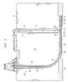
- FIG. 1is a cross-sectional diagram illustrating formation of a multi-well system for accessing a subterranean zone from the surface in accordance with one embodiment of the present invention
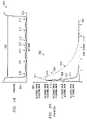
- FIG. 2is a cross-sectional diagram illustrating formation of the multi-well system for accessing the subterranean zone from the surface in accordance with another embodiment of the present invention
- FIGS. 3A–Bare cross-sectional diagrams illustrating production from the subterranean zone to the surface using the multi-well system in accordance with several embodiments of the present invention
- FIG. 4is a top plan diagram illustrating a pinnate well bore pattern for accessing products in the subterranean zone in accordance with one embodiment of the present invention
- FIG. 5is a top plan diagram illustrating a pinnate well bore pattern for accessing products in the subterranean zone in accordance with another embodiment of the present invention
- FIG. 6is a top plan diagram illustrating a quad-pinnate well bore pattern for accessing products in the subterranean zone in accordance with one embodiment of the present invention
- FIG. 7is a top plan diagram illustrating an alignment of pinnate well bore patterns in the subterranean zone in accordance with one embodiment of the present invention.
- FIG. 8is a top plan diagram illustrating a pinnate well bore pattern for accessing products in the subterranean zone in accordance with another embodiment of the present invention.
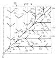
- FIG. 9is a top plan diagram illustrating a pinnate well bore pattern for accessing products in the subterranean zone in accordance with still another embodiment of the present invention.
- FIG. 10is a top plan diagram illustrating a pinnate well bore pattern for accessing products in the subterranean zone in accordance with still another embodiment of the present invention.
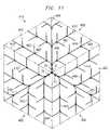
- FIG. 11is a top plan diagram illustrating a tri-pinnate well bore pattern for accessing products in the subterranean zone in accordance with one embodiment of the present invention
- FIG. 12is a top plan diagram illustrating an alignment of tri-pinnate well bore patterns in the subterranean zone in accordance with one embodiment of the present invention.
- FIG. 13is a top plan diagram illustrating a pinnate well bore pattern for accessing products in the subterranean zone in accordance with still another embodiment of the present invention.
- FIG. 14is a diagram illustrating a multi-well system for accessing a subterranean zone from a limited surface area in accordance with one embodiment of the present invention
- FIG. 15is a diagram illustrating the matrix structure of coal in accordance with one embodiment of the present invention.
- FIG. 16is a diagram illustrating natural fractures in a coal seam in accordance with one embodiment of the present invention.
- FIG. 17is a top plan diagram illustrating pressure drop in the subterranean zone across a coverage area of the pinnate well bore pattern of FIG. 8 during production of gas and water in accordance with one embodiment of the present invention
- FIG. 18is a chart illustrating pressure drop in the subterranean zone across line 18 — 18 of FIG. 17 in accordance with one embodiment of the present invention
- FIG. 19is a flow diagram illustrating a method for surface production of gas from the coverage area of the subterranean zone in accordance with embodiment of the present invention.
- FIG. 20is a graph illustrating production curves for gas and water from the coverage area of the subterranean zone in accordance with one embodiment of the present invention.
- FIG. 21is a graph illustrating simulated cumulative gas production curves for a multi-lateral well as a function of lateral spacing in accordance with one embodiment of the present invention.
- FIG. 1illustrates formation of a dual well system 10 for enhanced access to a subterranean, or subsurface, zone from the surface in accordance with an embodiment of the present invention.
- the subterranean zoneis a tight coal seam having a medium to low permeability.
- the zonemay be a shale or other carbonaceous formation.
- the system 10includes a well bore 12 extending from the surface 14 to a target coal seam 15 .
- the well bore 12intersects, penetrates and continues below the coal seam 15 .
- the well bore 12may be lined with a suitable well casing 16 that terminates at or above the level of the coal seam 15 .
- the well bore 12is substantially vertical or non-articulated in that it allows sucker rod, Moineau and other suitable rod, screw and/or other efficient bore hole pumps or pumping system to lift fluids up the bore 12 to the surface 14 .
- the well bore 12may include suitable angles to accommodate surface 14 characteristics, geometric characteristics of the coal seam 15 , characteristics of intermediate formations and may be slanted at a suitable angle or angles along its length or parts of its length. In particular embodiments, the well bore 12 may slant up to 35 degrees along its length or in sections but not itself be fully articulated to horizontal.
- the well bore 12may be logged either during or after drilling in order to closely approximate and/or locate the exact vertical depth of the coal seam 15 . As a result, the coal seam 15 is not missed in subsequent drilling operations. In addition, techniques used to locate the coal seam 15 while drilling need not be employed. The coal seam 15 may be otherwise suitably located.
- An enlarged cavity 20is formed in the well bore 12 in or otherwise proximate to the coal seam 15 .
- the enlarged cavity 20provides a point for intersection of the well bore 12 by an articulated well bore used to form a horizontal multi-branching or other suitable subterranean well bore pattern in the coal seam 15 .
- the enlarged cavity 20also provides a collection point for fluids drained from the coal seam 15 during production operations and may additionally function as a gas/water separator and/or a surge chamber.
- the cavitymay be omitted and the wells may intersect to form a junction or may intersect at any other suitable type of junction.
- the cavity 20is an enlarged area of one or both well bores and may have any suitable configuration.
- the cavity 20has an enlarged radius of approximately eight feet and a vertical dimension that equals or exceeds the vertical dimension of the coal seam 15 .
- the cavity 20may have an enlarged substantially rectangular cross section perpendicular to an articulated well bore for intersection by the articulated well bore and a narrow width through which the articulated well bore passes.
- the enlarged cavity 20may be formed using suitable under-reaming techniques and equipment such as a dual blade tool using centrifugal force, ratcheting or a piston for actuation, a pantograph and the like.
- the cavitymay be otherwise formed by fracing and the like.
- a portion of the well bore 12may continue below the cavity 20 to form a sump 22 for the cavity 20 .
- well 12may be capped with a suitable well head.
- the articulated well bore 30extends from the surface 14 to the enlarged cavity 20 of the well bore 12 .
- the articulated well bore 30may include a portion 32 , a portion 34 , and a curved or radiused portion 36 interconnecting the portions 32 and 34 .
- the portion 32is substantially vertical, and thus may include a suitable slope. As previously described, portion 32 may be formed at any suitable angle relative to the surface 14 to accommodate surface 14 geometric characteristics and attitudes and/or the geometric configuration or attitude of the coal seam 15 .
- the portion 34is substantially horizontal in that it lies substantially in the plane of the coal seam 15 . The portion 34 intersects the cavity 20 of the well bore 12 .
- portion 34may be formed at any suitable angle relative to the surface 14 to accommodate the dip or other geometric characteristics of the coal seam 15 . It will also be understood that the curved or radius portion 36 may directly intersect the cavity 20 and that the portion 34 may undulate, be formed partially or entirely outside the coal seam 15 and/or may be suitably angled.
- the articulated well bore 30is offset a sufficient distance from the well bore 12 at the surface 14 to permit the large radius curved section 36 and any desired portion 34 to be drilled before intersecting the enlarged cavity 20 .
- the articulated well bore 30may be offset a distance of about 300 feet from the well bore 12 . This spacing reduces or minimizes the angle of the curved portion 36 to reduce friction in the articulated well bore 30 during drilling operations. As a result, reach of the drill string through the articulated well bore 30 is increased and/or maximized.
- the articulated well bore 30may be located within close proximity of the well bore 12 at the surface 14 to minimize the surface area for drilling and production operations.
- the well bore 12may be suitably sloped or radiused to extend down and over to a junction with the articulated bore 30 .
- the multi-well systemmay have a vertical profile with a limited surface well bore area, a substantially larger subsurface well bore junction area and a still substantially larger subsurface coverage area.
- the surface well bore areamay be minimized to limit environmental impact.
- the subsurface well bore junction areamay be enlarged with respect to the surface area due to the use of large-radius curves for formation of the horizontal drainage pattern.
- the subsurface coverage areais drained by the horizontal pattern and may be optimized for drainage and production of gas from the coal seam 15 or other suitable subterranean zone.
- the articulated well bore 30is drilled using a drill string 40 that includes a suitable down-hole motor and bit 42 .
- a measurement while drilling (MWD) device 44is included in the articulated drill string 40 for controlling the orientation and direction of the well bore drilled by the motor and bit 42 .
- the portion 32 of the articulated well bore 30is lined with a suitable casing 38 .
- the well bore 12 and/or cavity 20may be otherwise positioned relative to the well bore pattern 50 and the articulated well 30 .
- the well bore 12 and cavity 20may be positioned at an end of the well bore pattern 50 distant from the articulated well 50 .
- the well bore 12 and/or cavity 20may be positioned within the pattern 50 at or between sets of laterals.
- portion 34 of the articulated wellmay have any suitable length and itself form the well bore pattern 50 or a portion of the pattern 50 .
- pattern 50may be otherwise formed or connected to the cavity 20 .
- the well bore pattern 50may be substantially horizontal corresponding to the geometric characteristics of the coal seam 15 .
- the well bore pattern 50may include sloped, undulating, or other inclinations of the coal seam 15 or other subterranean zone.
- gamma ray logging tools and conventional MWD devicesmay be employed to control and direct the orientation of the drill bit 42 to retain the well bore pattern 50 within the confines of the coal seam 15 and to provide substantially uniform coverage of a desired area within the coal seam 15 .
- the drainage pattern 50may be an omni-directional pattern operable to intersect a substantial or other suitable number of fractures in the area of the coal seam 15 covered by the pattern 50 .
- the drainage pattern 50may intersect a significant number of fractures of the coal seam 15 when it intersects a majority of the fractures in the coverage area and plane of the pattern 50 .
- the drainage pattern 50may intersect five, ten, twenty-five, forty or other minority percentage of the fractures or intersect sixty, seventy-five, eighty or other majority or super majority percentage of the fractures in the coverage area and plane of the pattern 50 .
- the coverage areamay be the area between the well bores of the drainage network of the pattern 50 .
- the drainage pattern 50may be a pinnate pattern, other suitable multi-lateral or multi-branching pattern, other pattern having a lateral or other network of bores or other patterns of one or more bores with a significant percentage of the total footage of the bores having disparate orientations.
- the percentage of the bores having disparate orientationsis significant when twenty-five to seventy-five percent of the bores have an orientation at least twenty degrees offset from other bores of the pattern.
- the well bores of the pattern 50may have three or more main orientations each including at least 10 percent of the total footage of the bores.
- the pattern 50may have a plurality of bores extending outward of a center point.
- the boresmay be oriented with a substantially equal radial spacing between them.
- the boresmay in some embodiments be main bores with a plurality of lateral bores extending from each main bore. In another embodiment, the radially extending bores may together and alone form a multi-lateral pattern.
- drilling fluid or “mud”is pumped down the drill string 40 and circulated out of the drill string 40 in the vicinity of the bit 42 , where it is used to scour the formation and to remove formation cuttings.
- the cuttingsare then entrained in the drilling fluid which circulates up through the annulus between the drill string 40 and the walls of well bore 30 until it reaches the surface 14 , where the cuttings are removed from the drilling fluid and the fluid is then recirculated.
- This conventional drilling operationproduces a standard column of drilling fluid having a vertical height equal to the depth of the well bore 30 and produces a hydrostatic pressure on the well bore 30 corresponding to the well bore 30 depth.
- coal seams 15tend to be porous and fractured, they may be unable to sustain such hydrostatic pressure, even if formation water is also present in the coal seam 15 . Accordingly, if the full hydrostatic pressure is allowed to act on the coal seam 15 , the result may be loss of drilling fluid and entrained cuttings into the formation. Such a circumstance is referred to as an over-balanced drilling operation in which the hydrostatic fluid pressure in the well bore 30 exceeds the ability of the formation to withstand the pressure. Loss of drilling fluids and cuttings into the formation not only is expensive in terms of the lost drilling fluids, which must be made up, but it also tends to plug the pores in the coal seam 15 , which are needed to drain the coal seam 15 of gas and water.
- air compressors 60may be provided to circulate compressed air down the well bore 12 and back up through the articulated well bore 30 .
- the circulated airwill admix with the drilling fluids in the annulus around the drill string 40 and create bubbles throughout the column of drilling fluid. This has the effect of lightening the hydrostatic pressure of the drilling fluid and reducing the down-hole pressure sufficiently that drilling conditions do not become over-balanced.
- Aeration of the drilling fluidreduces down-hole pressure to less than the pressure of the hydrostatic column.
- down-hole pressuremay be reduced to approximately 150–200 pounds per square inch (psi). Accordingly, low pressure coal seams and other subterranean resources can be drilled without substantial loss of drilling fluid and contamination of the resource by the drilling fluid.
- Foamwhich may be compressed air mixed with water or other suitable fluid, may also be circulated down through the drill string 40 along with the drilling mud in order to aerate the drilling fluid in the annulus as the articulated well bore 30 is being drilled and, if desired, as the well bore pattern 50 is being drilled.
- Drilling of the well bore pattern 50 with the use of an air hammer bit or an air-powered down-hole motorwill also supply compressed air or foam to the drilling fluid.
- the compressed air or foam which is used to power the down-hole motor and bit 42exits the articulated drill string 40 in the vicinity of the drill bit 42 .
- the larger volume of air which can be circulated down the well bore 12permits greater aeration of the drilling fluid than generally is possible by air supplied through the drill string 40 .
- FIG. 2is a diagram illustrating formation of the multi-well system 10 in accordance with another embodiment of the present invention.
- the well bore 12 , cavity 20 and articulated well bore 30are positioned and formed as previously described in connection with FIG. 1 .
- a Moineau or other suitable pump 52is installed in the cavity 20 to pump drilling fluid and cuttings to the surface 14 through the well bore 12 .
- FIGS. 3A–Billustrate production from the coal seam 15 to the surface using the multi-well system 10 in accordance with several embodiments of the present invention.
- FIG. 3Aillustrates the use of gas lift to produce water from a coal seam 15 .
- FIG. 3Billustrates the use of a rod pump to produce water from the coal seam 15 .
- water productionmay be initiated by gas lift to clean out the cavity 20 and kick-off production. After production kick-off, the gas lift equipment may be replaced with a rod pump for further removal of water during the life of the well.
- the gas lift systemmay be replaced with a rod pump for further and/or continued removal of water from the cavity 20 over the life of the well.
- evolving gas disorbed from coal in the seam 15 and produced to the surface 14is collected at the well head and after fluid separation may be flared, stored or fed into a pipeline.
- water pressuremay need to be reduced below the initial reservoir pressure of an area of the coal seam 15 before methane and other gas will start to diffuse or disorb from the coal in that area.
- the initial reservoir pressureis typically about 300 psi.
- pressuremay need to be reduced well below initial reservoir pressure down to the critical disorbtion pressure.
- Sufficient reduction in the water pressure for gas productionmay take weeks and/or months depending on configuration of the well bore pattern 50 , water recharge in the coal seam 15 , cavity pumping rates and/or any subsurface drainage through mines and other man made or natural structures that drain water from the coal seam 15 without surface lift.
- reservoir pressuremay similarly need to be reduced before methane gas will start to diffuse or disorb from coal in the coverage area.
- Free and near-well bore gasmay be produced prior to the substantial reduction in reservoir pressure or the start of disorbtion.
- the amount of gas disorbed from coalmay increase exponentially or with other non-linear geometric progression with a drop in reservoir pressure. In this type of coal seam, gas lift, rod pumps and other water production equipment may be omitted.
- the drill string 40is removed from the articulated well bore 30 and the articulated well bore 30 is capped.
- a tubing string 70is disposed into well bore 12 with a port 72 positioned in the enlarged cavity 20 .
- the enlarged cavity 20provides a reservoir for water or other fluids collected through the drainage pattern 50 from the coal seam 15 .
- the tubing string 70may be a casing string for a rod pump to be installed after the completion of gas lift and the port 72 may be the intake port for the rod pump.
- the tubingmay be a 27 ⁇ 8 tubing used for a rod pump. It will be understood that other suitable types of tubing operable to carry air or other gases or materials suitable for gas lift may be used.
- an air compressor 74is connected to the tubing string 70 . Air compressed by the compressor 74 is pumped down the tubing string 70 and exits into the cavity 20 at the port 72 .
- the air used for gas lift and/or for the previously described under balanced drillingmay be ambient air at the site or may be or include any other suitable gas.
- produced gasmay be returned to the cavity and used for gas lift.
- the compressed airexpands and suspends liquid droplets within its volume and lifts them to the surface.
- airmay be compressed to three hundred to three hundred fifty psi and provided at a rate of nine hundred cubic feet per minute (CFM). At this rate and pressure, the gas lift system may lift up to three thousand, four thousand or five thousand barrels a day of water to the surface.
- a fluid separator 76At the surface, air and fluids are fed into a fluid separator 76 .
- Produced gas and lift airmay be outlet at air/gas port 78 and flared while remaining fluids are outlet at fluid port 79 for transport or other removal, reinjection or surface runoff.
- watermay be otherwise suitably removed from the cavity 20 and/or drainage pattern 50 without production to the surface.
- the watermay be reinjected into an adjacent or other underground structure by pumping, directing or allowing the flow of the water to the other structure.
- the rate and/or pressure of compressed air provided to the cavitymay be adjusted to control the volume of water produced to the surface.
- a sufficient rate and/or pressure of compressed airmay be provided to the cavity 20 to lift all or substantially all of the water collected by the cavity 20 from a coal seam 15 . This may provide for a rapid pressure drop in the coverage area of the coal seam 15 and allow for kick-off of the well to self-sustaining flow within one, two or a few weeks.
- the rate and/or pressure of air providedmay be controlled to limit water production below the attainable amount due to limitations in disposing of produced water and/or damage to the coal seam 15 or equipment by high rates of production.
- a turbidity metermay be used at the well head to monitor the presence of particles in the produced water. If the amount of particles is over a specified limit, a controller may adjust a flow control valve to reduce the production rate. The controller may adjust the valve to specific flow rates and/or use feedback from the turbidity meter to adjust the flow control valve to a point where the amount of particles in the water is at a specified amount.
- a pumping unit 80is disposed in the well bore 12 and extends to the enlarged cavity 20 .
- the enlarged cavity 20provides a reservoir for accumulated fluids that may act as a surge tank and that may allow intermittent pumping without adverse effects of a hydrostatic head caused by accumulated fluids in the well bore 12 .
- a large volume of fluidsmay be collected in the cavity 20 without any pressure or any substantial pressure being exerted on the formation from the collected fluids.
- water and/or gasmay continue to flow from the well bore pattern 50 and accumulate in the cavity 20 .
- the pumping unit 80includes an inlet port 82 in the cavity 20 and may comprise a tubing string 83 with sucker rods 84 extending through the tubing string 83 .
- the inlet 82may be positioned at or just above a center height of the cavity 20 to avoid gas lock and to avoid debris that collects in the sump 22 of the cavity 20 .
- the inlet 82may be suitably angled with or within the cavity.
- the sucker rods 84are reciprocated by a suitable surface mounted apparatus, such as a powered walking beam 86 to operate the pumping unit 80 .
- the pumping unit 80may comprise a Moineau or other suitable pump operable to lift fluids vertically or substantially vertically.
- the pumping unit 80is used to remove water and entrained coal fines from the coal seam 15 via the well bore pattern 50 . Once the water is removed to the surface 14 , it may be treated in gas/water separator 76 for separation of methane which may be dissolved in the water and for removal of entrained fines.
- coal seam gasmay flow from the coal seam 15 to the surface 14 through the annulus of the well bore 12 around the tubing string 83 and be removed via piping attached to a wellhead apparatus.
- the pumping unit 80may be operated continuously or as needed to remove water drained from the coal seam 15 into the enlarged cavity 20 .
- gas liftis continued until the well is kicked-off to a self-sustaining flow at which time the well is briefly shut-in to allow replacement of the gas lift equipment with the fluid pumping equipment.
- the wellis then allowed to flow in self-sustaining flow subject to periodic periods of being shut-in for maintenance, lack of demand for gas and the like.
- the wellmay need to be pumped for a few cycles, a few hours, days or weeks, to again initiate self-sustaining flow or other suitable production rate of gas.
- the rod pumpmay produce approximately eight gallons per minute of water from the cavity 20 to the surface.
- the wellis at self sustaining flow when the flow of gas is operable to lift any produced water such that the well may operate for an extended period of six weeks or more without pumping or artificial gas lift.
- the wellmay require periodic pumping between periods of self sustaining flow.
- the well bore pattern 50may be configured to result in a net reduction of water volume in the coverage area of the drainage pattern (overall water volume pumped to the surface 14 less influx water volume from the surrounding areas and/or formations) of one tenth of the initial insitu water volume in the first five to ten days of water production with gas lift or in the first 17 to 25 days of water production with a rod pump in order to kick-off or induce early and/or self-sustaining gas release.
- the start of water productionmay be the initial blow down or pump down of the well during a post-drilling testing and/or production phase.
- early or accelerated gas releasemay be through a chain reaction through an ever reducing reservoir pressure.
- Self-sustaining gas releaseprovides gas lift to remove water without further pumping. Such gas may be produced in two-phase flow with the water.
- the blow down or rapid removal of water from the coverage area of the coal seam 15may provide a pull or “jerk” on the formation and the high rate of flow in the bores may create an eductor affect in the intersecting fractures to “pull” water and gas from the coal seam 15 .
- the released gasmay lower the specific gravity and/or viscosity of the produced fluid thereby further accelerating gas production from the formation.
- the released gasmay act as a propellant for further two-phase flow and/or production.
- the pressure reductionmay affect a large rock volume causing a bulk coal or other formation matrix shrinkage and further accelerating gas release.
- an attended increase in cleat widthmay increase formation permeability and thereby further expedite gas production from the formation. It will be understood that early gas release may be initiated with all, some or none of the further enhancements to production.
- a majority or other substantial portion of water and gas from the coal seam 15may flow into the drainage pattern 50 for production to the surface through intersections of the pattern 50 with natural fractures in the coal seam 15 . Due to the size of the fractures, the disabsorption of gas from coal that lowers the relative permeability of the coal matrix to gas and/or water to less than twenty percent of the absolute permeability does not affect or substantially affect flow into the pattern 50 from the fractures. As a result, gas and water may be produced in substantial qualities in formations having medium and low effective permeability despite low relative permeabilities of the formations.
- FIGS. 4–14illustrate well bore or drainage patterns 50 for accessing the coal seam 15 or other subterranean zone in accordance with various embodiments of the present invention.
- the pattern 50may be used to remove or inject water.
- the well bore patterns 50comprise one or more pinnate well bore patterns that each have a central diagonal or other main bore with generally symmetrically arranged and appropriately spaced laterals extending from each side of the diagonal.
- the term eachmeans every one of at least a subset of the identified items. It will be understood that other suitable multi-branching patterns including or connected to a surface production bore and having the significant percentage of their total length at different angles, directions or orientations than each other or the production bore may be used without departing from the scope of the present invention.
- the pinnate patternsapproximate the pattern of veins in a leaf or the design of a feather in that it has similar, substantially parallel, auxiliary drainage bores arranged in substantially equal and parallel spacing on opposite sides of an axis.
- the pinnate drainage patterns with their central bore and generally symmetrically arranged and appropriately spaced auxiliary drainage bores on each sideprovide a substantially uniform pattern for draining fluids from a coal seam 15 or other subterranean formation.
- the number and spacing of the lateral boresmay be adjusted depending on the absolute, relative and/or effective permeability of the coal seam and the size of the area covered by the pattern.
- the area covered by the patternmay be the area drained by the pattern, the area of a spacing unit that the pattern is designed to drain, the area within the distal points or periphery of the pattern and/or the area within the periphery of the pattern as well as the surrounding area out to a periphery intermediate to adjacent or neighboring patterns.
- the coverage areamay also include the depth, or thickness of the coal seam or, for thick coal seams, a portion of the thickness of the seam.
- the patternmay include upward or downward extending branches in addition to horizontal branches.
- the lateralsmay be spaced approximately six hundred feet apart from each other.
- the lateral spacingmay be four hundred feet. The effective permeability may be determined by well testing and/or analysis of long-term production trends.
- the pinnate patternsmay provide substantially uniform coverage of a quadrilateral or other non-disjointed area having a high area to perimeter ratio. Coverage is substantially uniform when, except for pressure due to hydrostatic head, friction or blockage, the pressure differential across the coverage area is less than or equal to twenty psi for a mature well the differential at any time after an initial month of production is less than twenty psi or when less than ten percent of the area bounded by the pattern comprises trapped cells. In a particular embodiment, the pressure differential may be less than ten psi.
- the coverage areamay be a square, other quadrilateral, or other polygon, circular, oval or other ellipsoid or grid area and may be nested with other patterns of the same or similar type. It will be understood that other suitable well bore patterns 50 may be used in accordance with the present invention.
- the pinnate and other suitable well bore patterns 50 drilled from the surface 14provide surface access to subterranean formations.
- the well bore pattern 50may be used to uniformly remove and/or insert fluids or otherwise manipulate a subterranean zone.
- the well bore pattern 50may be used initiating in-situ burns, “huff-puff” steam operations for heavy crude oil, and the removal of hydrocarbons from low porosity reservoirs.
- the well bore pattern 50may also be used to uniformly inject or introduce a gas, fluid or other substance into a subterranean zone. For example, carbon dioxide may be injected into a coal seam for sequestration through the pattern 50 .
- FIG. 4illustrates a pinnate well bore pattern 100 in accordance with one embodiment of the present invention.
- the pinnate well bore pattern 100provides access to a substantially square coverage area 102 of the subterranean zone.
- a number of the pinnate well bore patterns 100may be used together to provide uniform access to a large subterranean region.
- the enlarged cavity 20defines a first corner of the area 102 .
- the pinnate pattern 100includes a main well bore 104 extending diagonally across the coverage area 102 to a distant corner 106 of the area 102 .
- the well bores 12 and 30are positioned over the area 102 such that the main well bore 104 is drilled up the slope of the coal seam 15 . This may facilitate collection of water, gas, and other fluids from the area 102 .
- the well bore 104is drilled using the drill string 40 and extends from the enlarged cavity 20 in alignment with the articulated well bore 30 .
- a plurality of lateral well bores 110extend from opposites sides of well bore 104 to a periphery 112 of the area 102 .
- the lateral bores 110may mirror each other on opposite sides of the well bore 104 or may be offset from each other along the well bore 104 .
- Each of the lateral bores 110includes a radius curving portion 114 extending from the well bore 104 and an elongated portion 116 formed after the curved portion 114 has reached a desired orientation.
- pairs of lateral bores 110may be substantially evenly spaced on each side of the well bore 104 and extend from the well bore 104 at an angle of approximately 45 degrees.
- the lateral bores 110shorten in length based on progression away from the enlarged cavity 20 .
- the pinnate well bore pattern 100 using a single well bore 104 and five pairs of lateral bores 110may drain a coal seam area of approximately 150 acres in size.
- alternate pinnate well bore patternsmay be employed by varying the angle of the lateral bores 110 to the well bore 104 and the orientation of the lateral bores 110 .
- lateral bores 110can be drilled from only one side of the well bore 104 to form a one-half pinnate pattern.
- the well bore 104 and the lateral bores 110 of pattern 100 as well as bores of other patternsare formed by drilling through the enlarged cavity 20 using the drill string 40 and an appropriate drilling apparatus.
- gamma ray logging tools and conventional MWD technologiesmay be employed to control the direction and orientation of the drill bit 42 so as to retain the well bore pattern within the confines of the coal seam 15 and to maintain proper spacing and orientation of the well bores 104 and 110 .
- the well bore 104 and that of other patternsare drilled with an incline at each of a plurality of lateral branch points 108 .
- the articulated drill string 40is backed up to each successive lateral point 108 from which a lateral bore 110 is drilled on each side of the well bore 104 .
- the pinnate drainage pattern 100may be otherwise suitably formed.
- FIG. 5illustrates a pinnate well bore pattern 120 in accordance with another embodiment of the present invention.
- the pinnate well bore pattern 120drains a substantially rectangular area 122 of the coal seam 15 .
- the pinnate well bore pattern 120includes a main well bore 124 and a plurality of lateral bores 126 that are formed as described in connection with well bores 104 and 110 of FIG. 4 .
- the lateral well bores 126 on a first side of the well bore 124include a shallow angle while the lateral bores 126 on the opposite side of the well bore 124 include a steeper angle to together provide uniform coverage of the area 122 .
- FIG. 6illustrates a quad-pinnate well bore pattern 140 in accordance with one embodiment of the present invention.
- the quad-pinnate well bore pattern 140includes four discrete sub-patterns extending from a substantial center of the area.
- the wellsare interconnected in that the articulated bores are drilled from the same surface bore.
- a plurality of sub-patternsmay be formed from main bores extending away from a substantial center of an area in different directions.
- the main boresmay be substantially evenly oriented about the center to uniform coverage and may be the same, substantially the same or different from each other.
- the sub-patternsmay each be a pinnate well bore patterns 100 that access a quadrant of a region 142 covered by the pinnate well bore pattern 140 .
- Each of the pinnate well bore patterns 100includes a main well bore 104 and a plurality of lateral well bores 110 extending from the well bore 104 .
- each of the well bores 104 and 110is drilled from a common articulated well bore 30 through a cavity 20 . This allows tighter spacing of the surface production equipment, wider coverage of a well bore pattern, and reduces drilling equipment and/or operations.
- FIG. 7illustrates the alignment of pinnate well bore patterns 100 with planned subterranean structures of a coal seam 15 for degasifying and preparing the coal seam 15 for mining operations in accordance with one embodiment of the present invention.
- the coal seam 15will be mined using a longwall process. It will be understood that the present invention can be used to degasify coal seams for other types of mining operations.
- planned coal panels 150extend longitudinally from a longwall 152 .
- each panel 150will be subsequently mined from a distant end toward the longwall 152 and the mine roof allowed to cave and fracture into the opening behind the mining process.
- the pinnate well bore patterns 100Prior to mining, the pinnate well bore patterns 100 are drilled into the panels 150 from the surface to degasify the panels 150 well ahead of mining operations.
- Each of the pinnate well bore patterns 100is aligned with the planned longwall 152 and panel 150 grid and covers portions of one or more panels 150 . In this way, a region of a planned mine can be degasified from the surface based on subterranean structures and constraints, allowing a subsurface formation to be degasified and mined within a short period of time.
- FIG. 8illustrates a pinnate well bore pattern 200 in accordance with another embodiment of the present invention.
- the pinnate well bore pattern 200provides access to a substantially square area 202 of a subterranean zone.
- a number of the pinnate patterns 200may be used together in dual, triple, and quad pinnate structures to provide uniform access to a large subterranean region.
- the enlarged cavity 20defines a first corner of the area 202 , over which a pinnate well bore pattern 200 extends.
- the enlarged cavity 20defines a first corner of the area 202 .
- the pinnate pattern 200includes a main well bore 204 extending diagonally across the area 202 to a distant corner 206 of the area 202 .
- the main well bore 204is drilled up the slope of the coal seam 15 . This may facilitate collection of water, gas, and other fluids from the area 202 .
- the main well bore 204is drilled using the drill string 40 and extends from the enlarged cavity 20 in alignment with the articulated well bore 30 .
- a plurality of lateral well bores 210extend from the opposite sides of well bore 204 to a periphery 212 of the area 202 .
- the lateral bores 210may mirror each other on opposite sides of the well bore 204 or may be offset from each other along the well bore 204 .
- Each of the lateral well bores 210includes a first radius curving portion 214 extending from the well bore 204 , and an elongated portion 218 .
- the first set of lateral well bores 210 located proximate to the cavity 20may also include a second radius curving portion 216 formed after the first curved portion 214 has reached a desired orientation. In this set, the elongated portion 218 is formed after the second curved portion 216 has reached a desired orientation.
- pairs of lateral well bores 210may be substantially evenly spaced on each side of the well bore 204 and extend from the well bore 204 at an angle of approximately 45 degrees.
- the lateral well bores 210shorten in length based on progression away from the enlarged cavity 20 .
- the lateral well bores 210lengthen based on proximity to the cavity 20 in order to provide an enlarged and uniform coverage area.
- the length from a tip of each lateral to the cavityis substantially equal and at or close to the maximum reach of the drill string through the articulated well 30 .
- FIG. 9illustrates a pinnate well bore pattern 300 in accordance with another embodiment of the present invention.
- the pinnate well bore pattern 300provides access to a substantially square area 302 of a subterranean zone.
- a number of the pinnate patterns 300may be used together to provide uniform access to a large subterranean region.
- the enlarged cavity 20defines a first corner of the area 302 .
- the pinnate well bore pattern 300includes a main well bore 304 extending diagonally across the area 302 to a distant corner 306 of the area 302 .
- the well bore 304is drilled up the slope of the coal seam 15 . This may facilitate collection of water, gas, and other fluids from the area 302 .
- the well bore 304is drilled using the drill string 40 and extends from the enlarged cavity 20 in alignment with the articulated well bore 30 .
- a set of lateral well bores 310extends from opposite sides of well bore 304 to a periphery 312 of the area 302 .
- the lateral well bores 310may mirror each other on opposite sides of the well bore 304 or may be offset from each other along the well bore 304 .
- Each of the lateral well bores 310includes a radius curving portion 314 extending from the well bore 304 and an elongated portion 316 formed after the curved portion 314 has reached a desired orientation.
- pairs of lateral well bores 310may be substantially evenly spaced on each side of the well bore 304 and extend from the well bore 304 at an angle of approximately 45 degrees.
- the lateral well bores 310may be formed at other suitable angular orientations relative to well bore 304 .
- the lateral well bores 310shorten in length based on progression away from the enlarged diameter cavity 20 .
- a distance to the periphery 312 for the pattern 300 as well as for other pinnate patterns from the cavity 20 or well bore 30 measured along the lateral well bores 310is substantially equal for each lateral well bore 310 , thereby enhancing coverage by drilling substantially to a maximum distance by each lateral.
- well bore pattern 300also includes a set of secondary lateral well bores 320 extending from lateral well bores 310 .
- the secondary lateral well bores 320may mirror each other on opposite sides of the lateral well bore 310 or may be offset from each other along the lateral well bore 310 .
- Each of the secondary lateral well bores 320includes a radius curving portion 322 extending from the lateral well bore 310 and an elongated portion 324 formed after the curved portion 322 has reached a desired orientation.
- pairs of secondary lateral well bores 320may be disposed substantially equally spaced on each side of the lateral well bore 310 .
- secondary lateral well bores 320 extending from one lateral well bore 310may be disposed to extend between secondary lateral well bores 320 extending from an adjacent lateral well bore 310 to provide uniform coverage of the area 302 .
- the quantity, spacing, and angular orientation of secondary lateral well bores 320may be varied to accommodate a variety of resource areas, sizes and drainage requirements. It will be understood that secondary lateral well bores 320 may be used in connection with other main laterals of other suitable pinnate patterns.
- FIG. 10illustrates a well bore pattern 400 in accordance with still another embodiment of the present invention.
- the well bore pattern 400provides access to a substantially diamond or parallelogram-shaped area 402 of a subterranean resource.
- a number of the well bore patterns 400may be used together to provide uniform access to a large subterranean region.
- the articulated well bore 30defines a first corner of the area 402 .
- the well bore pattern 400includes a main well bore 404 extending diagonally across the area 402 to a distant corner 406 of the area 402 .
- the well bores 12 and 30may be positioned over the area 402 such that the well bore 404 is drilled up the slope of the coal seam 15 . This may facilitate collection of water, gas, and other fluids from the area 402 .
- the well bore 404is drilled using the drill string 40 and extends from the enlarged cavity 20 in alignment with the articulated well bore 30 .
- a plurality of lateral well bores 410extend from the opposite sides of well bore 404 to a periphery 412 of the area 402 .
- the lateral well bores 410may mirror each other on opposite sides of the well bore 404 or may be offset from each other along the well bore 404 .
- Each of the lateral well bores 410includes a radius curving portion 414 extending from the well bore 404 and an elongated portion 416 formed after the curved portion 414 has reached a desired orientation.
- pairs of lateral well bores 410may be substantially equally spaced on each side of the well bore 404 and extend from the well bore 404 at an angle of approximately 60 degrees.
- the lateral well bores 410shorten in length based on progression away from the enlarged diameter cavity 20 .
- the quantity and spacing of lateral well bores 410may be varied to accommodate a variety of resource areas, sizes and well bore requirements.
- lateral well bores 410may be drilled from a single side of the well bore 404 to form a one-half pinnate pattern.
- FIG. 11illustrates a tri-pinnate well bore pattern 440 in accordance with one embodiment of the present invention.
- the tri-pinnate well bore pattern 440includes three discrete well bore patterns 400 each draining a portion of a region 442 covered by the well bore pattern 440 .
- Each of the well bore patterns 400includes a well bore 404 and a set of lateral well bores 410 extending from the well bore 404 .
- each of the well bores 404 and 410are drilled from a common articulated well bore 30 and fluid and/or gas may be removed from or introduced into the subterranean zone through a cavity 20 in communication with each well bore 404 . This allows tighter spacing of the surface production equipment, wider coverage of a well bore pattern and reduces drilling equipment and operations.
- Each well bore 404is formed at a location relative to other well bores 404 to accommodate access to a particular subterranean region.
- well bores 404may be formed having a spacing or a distance between adjacent well bores 404 to accommodate access to a subterranean region such that only three well bores 404 are required.
- the spacing between adjacent well bores 404may be varied to accommodate varied concentrations of resources of a subterranean zone. Therefore, the spacing between adjacent well bores 404 may be substantially equal or may vary to accommodate the unique characteristics of a particular subterranean resource. For example, in the embodiment illustrated in FIG.
- each well bore 404 and corresponding well bore pattern 400extends outwardly from well bore 444 in a different direction, thereby forming a substantially symmetrical pattern.
- the symmetrically formed well bore patternsmay be positioned or nested adjacent each other to provide substantially uniform access to a subterranean zone.
- each well bore pattern 400also includes a set of lateral well bores 448 extending from lateral well bores 410 .
- the lateral well bores 448may mirror each other on opposite sides of the lateral well bore 410 or may be offset from each other along the lateral well bore 410 .
- Each of the lateral well bores 448includes a radius curving portion 460 extending from the lateral well bore 410 and an elongated portion 462 formed after the curved portion 460 has reached a desired orientation.
- pairs of lateral well bores 448may be disposed substantially equally spaced on each side of the lateral well bore 410 .
- lateral well bores 448 extending from one lateral well bore 410may be disposed to extend between or proximate lateral well bores 448 extending from an adjacent lateral well bore 410 to provide uniform coverage of the region 442 .
- the quantity, spacing, and angular orientation of lateral well bores 448may be varied to accommodate a variety of resource areas, sizes and well bore requirements.
- each well bore pattern 400generally provides access to a quadrilaterally shaped area or region 402 .
- the region 402is substantially in the form of a diamond or parallelogram.
- the well bore patterns 400may be arranged such that sides 449 of each quadrilaterally shaped region 448 are disposed substantially in common with each other to provide uniform coverage of the region 442 .
- FIG. 12illustrates an alignment or nested arrangement of well bore patterns within a subterranean zone in accordance with an embodiment of the present invention.
- three discreet well bore patterns 400are used to form a series of generally hexagonally configured well bore patterns 450 , for example, similar to the well bore pattern 440 illustrated in FIG. 11 .
- the well bore pattern 450comprises a set of well bore sub-patterns, such as well bore patterns 400 , to obtain a desired geometrical configuration or access shape.
- the well bore patterns 450may be located relative to each other such that the well bore patterns 450 are nested in a generally honeycomb-shaped arrangement, thereby maximizing the area of access to a subterranean resource using fewer well bore patterns 450 .
- the well bore patterns 450Prior to mining of the subterranean resource, the well bore patterns 450 may be drilled from the surface to degasify the subterranean resource well ahead of mining operations.
- the quantity of discreet well bore patterns 400may also be varied to produce other geometrically-configured well bore patterns such that the resulting well bore patterns may be nested to provide uniform coverage of a subterranean resource.
- three discreet well bore patterns 400are illustrated in communication with a central well bore 404 , thereby forming a six-sided or hexagonally configured well bore pattern 440 and 450 .
- greater or fewer than three discreet well bore patterns 400may also be used in communication with a central well bore 404 such that a plurality of the resulting multi-sided well bore patterns may be nested together to provide uniform coverage of a subterranean resource and/or accommodate the geometric characteristics of a particular subterranean resource.
- the pinnate and quad-pinnate patternsmay be nested to provide uniform coverage of a subterranean field.
- FIG. 13illustrates a well bore pattern 500 in accordance with an embodiment of the present invention.
- well bore pattern 500comprises two discreet well bore patterns 502 each providing access to a portion of a region 504 covered by the well bore pattern 500 .
- Each of the well bore patterns 502includes a well bore 506 and a set of lateral well bores 508 extending from the well bore 506 .
- each of the well bores 506 and 508are drilled from a common articulated well bore 30 and fluid and/or gas may be removed from or introduced into the subterranean zone through the cavity 20 of well bore 12 in communication with each well bore 506 .
- well bores 20 and 30are illustrated offset from each other; however, it should be understood that well bore pattern 500 as well as other suitable pinnate patterns may also be formed using a common surface well bore configuration with the wells slanting or otherwise separating beneath the surface. This may allow tighter spacing of the surface production equipment, wider coverage of a well bore pattern and reduce drilling equipment and operations.
- each well bore pattern 502includes lateral well bores 508 extending from well bores 506 .
- the lateral well bores 508may mirror each other on opposite sides of the well bores 506 or may be offset from each other along the well bores 506 .
- Each of the lateral well bores 508includes a radius curving portion 518 extending from the well bore 506 and an elongated portion 520 formed after the curved portion 518 has reached a desired orientation.
- pairs of lateral well bores 508may be disposed substantially equally spaced on each side of the well bore 506 .
- the quantity, spacing, and angular orientation of lateral well bores 508may be varied to accommodate a variety of resource areas, sizes and well bore requirements.
- the lateral well bores 508may be formed such that the length of each lateral well bore 508 decreases as the distance between each respective lateral well bore 508 and the well bores 20 or 30 increases. Accordingly, the distance from the well bores 20 or 30 to a periphery of the region 504 along each lateral well bore 508 is substantially equal, thereby providing ease of well bore formation.
- each well bore pattern 502generally provides access to a triangular shaped area or region 522 .
- the triangular shaped regions 522are formed by disposing the lateral well bores 508 substantially orthogonal to the well bores 506 .
- the triangular shaped regions 522are disposed adjacent each other such that each region 522 has a side 524 substantially in common with each other.
- the combination of regions 522thereby forms a substantially quadrilateral shaped region 504 .
- multiple well bore patterns 500may be nested together to provide substantially uniform access to subterranean zones.
- FIG. 14illustrates a multi-well system for accessing a subterranean zone from a limited surface area in accordance with one embodiment of the present invention.
- a small surface well bore area 544 bounding the wells at the surfaceallows a limited drilling and production pad 536 size at the surface and thus may minimize or reduce environmental disturbance in the drilling and production site and/or allows accessing a large subterranean area from a roadside or other small area in steep or other terrain.
- suitable multi-well systemsmay be used for accessing a subterranean zone from a limited or other surface area without departing from the scope of the present invention.
- wells slanting in whole or in part from the surface with horizontal and/or other suitable patterns drilled off the slantmay be used in connection with the present invention without intersection of disparate surface wells.
- water or other fluids from one or more horizontal patternsoverflow into the slanted well where it is collected in a cavity or other bottom hole location and removed by gas lift or pumping to the surface or by diversion to another area or subterranean formation.
- a central surface well bore 532is disposed offset relative to a pattern of well bores 534 at the surface 536 and intersects each of the well bores 534 below the surface.
- the well bores 532 and 534are disposed in a substantially non-linear pattern in close proximity to each other to reduce or minimize the area required for the well bores 532 and 534 on the surface 536 .
- the well bores 534may be otherwise positioned at the surface relative to each other and the central articulating surface bore 532 .
- the boresmay have inline configuration.
- Well bore patterns 538are formed within target zone 540 exiting from cavities 542 located at the intersecting junctions of the well bores 532 and 534 .
- Well bore patterns 538may comprise pinnate patterns as illustrated by FIG. 8 , or may include other suitable patterns for accessing the zone 540 .
- the well bores 532 and 534may be disposed in close proximity to each other at the surface while providing generally uniform access to a large area of the target zone 540 .
- well bores 532 and 534may each be disposed within approximately thirty feet of another well and/or within two hundred feet, one hundred feet or less of every other well at the surface site while providing access to three hundred, five hundred, seven hundred fifty, one thousand or even twelve hundred or more acres in the zone 540 .
- the well bores 532 and 534may be disposed in a surface well bore area 544 less than two thousand, one thousand, seven hundred fifty, or even five hundred square feet, thereby reducing or minimizing the footprint required on the surface.
- the surface well bore area 544is a smallest quadrilateral that bounds the wells at the surface and may have the dimensions of thirty-two feet by thirty-two feet and form a substantial square or may have the dimensions of fifty feet by two hundred feet and form a substantial rectangle.
- the drilling pad 536may have an area of three-quarters of an acre for a tight well spacing at the surface with each well being within approximately thirty feet of at least one other well at the site.
- the surface pad 536may have an area of two acres with three-quarters of an acre for the center articulated well and one-quarter of an acre for each of four substantially vertical wells offset by about three hundred feet at the surface from the center well.
- the drilling pad 536may be a square or other suitable quadrilateral and may include small areas that jut out and/or in of the quadrilateral, polygonal or other shape of the pad.
- one or more sidesmay be non-linear and/or one or more corners may be non-congruent.
- well bore junctions or cavities 542 in wells 534may be horizontally displaced or outward of the surface location of the wells such that a subsurface well bore junction area 546 bounding the junctions is substantially larger in size than the surface well bore area.
- This junction placementis due to, or allows, large radius curves for formation of the horizontal pattern, which improves or optimizes the subsurface reach of drilling equipment to form the horizontal drainage pattern.
- the subsurface junction areais the smallest quadrilateral to include all the cavities formed from this site and, in this and other embodiments, may be between four and five acres.
- the coverage, or drainage areamay be still substantially larger covering three hundred, five hundred or more acres in the zone 540 .
- the multi-well systemprovides a vertical profile with a minimal or limited surface area and impact; enlarged, optimized or maximized subsurface drainage area; and an intermediate subsurface junction area to which fluids from the drainage pattern flow for collection and production to the surface.
- FIG. 15illustrates the matrix structure 550 of coal in the seam 15 in accordance with one embodiment of the present invention.
- the coalmay be bright banded coal with closely spaced cleats, dull banded coal with widely spaced cleats and/or other suitable types of coals.
- the coal structure 550includes bedding planes 552 , face, or primary, cleats 554 , and butt, or secondary, cleats 556 .
- the face and butt cleats 554 and 556are perpendicular to the bedding plane 552 and to each other.
- the face and butt cleats 554 and 556may have a spacing between cleavage planes of one-eighth to one half of an inch.
- the coal structure 550has a medium effective permeability between three and ten millidarcies or a low effective permeability of below three millidarcies.
- the coal structure 550may have an ultra low effective permeability below one millidarcy.
- Permeabilityis the capacity of a matrix to transmit a fluid and is the measure of the relative ease of fluid flow under an equal pressure drop.
- Effective permeabilityis a permeability of the coal or other formation matrix to gas or water and may be determined by well testing and/or long-term trends. For example, effective permeability may be determined by insitu slug tests, injection or draw down tests or other suitable direct or indirect well testing methods.
- Effective permeabilitymay also be determined based on suitable data and modeling.
- the effective permeabilityis the matrix or formation permeability and may change during the life of a well.
- the effective permeability of a formation and/or area of a formationis the median or mean effective permeability at substantially continuous flow conditions or simulated substantially continuous flow conditions of a formation or area over the life of the well, or over the period during which a majority of gas in the area is produced.
- the coal structure 550may also have a medium absolute permeability between three and millidarcies or a low absolute permeability below three millidarcies.
- Absolute permeabilityis the ability of the matrix to conduct a fluid, such as a gas or liquid at one hundred percent saturation of that fluid.
- the relative permeability of the formationis the relationship between the permeability to gas versus the permeability to water.
- the bulk coal matrix 550may shrink as it releases methane and causes an attendant increase in the width of the face and/or butt cleats 554 and 556 .
- the increase in cleat widthmay increase permeability, which may further accelerate removal of water and gas from the coal seam 15 .
- FIG. 16illustrates the structure 580 of an area of the coal seam 15 in accordance with one embodiment of the present invention.
- the coal bed structure 580includes natural fractures 582 , 584 and 586 .
- the natural fracturesmay be interconnected bedding planes, face cleats and/or butt cleats.
- the natural fracturesmay have one or more primary orientations in the coal seam that are perpendicular to each other and may hydraulically connect a series of smaller scale cleats.
- the natural fracturesform high capacity pathways, may increase system permeability by an order of magnitude and thus may not suffer large reductions in permeability through relative permeability effects in medium and low permeability coals.
- gasevolves from the coal matrix 550 .
- the presence of gas in two-phase flow with the watermay, for example, reduce the relative permeability of the coal matrix 550 relative to gas down to less than five percent of the absolute permeability.
- the relative permeability of the coal matrix relative to gasmay be reduced down to between three and twenty percent of absolute permeability or down to between eighteen and thirty percent of absolute permeability.
- the relative permeabilitymay increase up to about twelve percent of absolute permeability at an irreducible water saturation.
- the irreducible water saturationmay be at about seventy to eighty percent of full saturation.
- FIGS. 17–18illustrate provision of a well bore pattern 50 in a coal seam 15 and pressure drop across a coverage area of the pattern 50 in accordance with one embodiment of the present invention.
- the well bore pattern 50is the pinnate pattern 200 described in connection with FIG. 8 . It will be understood that the other pinnate and suitable multi-branching patterns may generate a similar pressure drop across the coverage area.
- the pinnate pattern 200is provided in the coal seam 15 by forming the pattern in the coal seam 15 , having the pattern formed, or using a preexisting pattern.
- the pinnate pattern 200includes the main bore 204 and a plurality of equally spaced laterals 210 . Laterals 210 are substantially perpendicular to each other and offset from the main bore by forty-five degrees.
- the pattern 200is omni-directional in that significant portions of bore length have disparate orientations.
- the omni-directional nature of the pinnate pattern 200may allow the pattern to intersect a substantial or other suitable percentage of the natural fractures 582 , 584 and 586 of the coal seam 15 regardless of the orientation of the pattern in the seam magnifying the effective well bore radius.
- the natural fracturesmay carry a majority or other suitable portion of gas and water from the coal seam 15 into the pinnate pattern 200 for collection at the cavity 20 and production to the surface 14 .
- the pinnate pattern 200may cover an area of two hundred fifty acres, have a substantially equal width to length ratio and have the laterals 210 each spaced approximately eight hundred feet apart. In this embodiment, a substantial portion of the coverage area 202 may be within four hundred feet from the main and/or lateral bores 204 and 210 with over fifty percent of the coverage area 202 being more than one hundred fifty to two hundred feet away from the bores.
- the pattern 200in conjunction with a pump, may be operable to expose and drain five hundred barrels per day of water, of which about ninety percent may be non recharge water. In gas lift and other embodiments, up to and/or over four thousand or five thousand barrels per day of water may be removed.
- Opposing bores 204 and/or 210 of the pinnate pattern 200cooperate with each other to drain the intermediate area of the formation and thus reduce pressure of the formation.
- the sectionis drained by the nearest bore 204 and/or 210 resulting in a uniform drop in pressure between the bores.
- a pressure distribution 600may be steadily reduced during production.
- the main and lateral well bores 204 and 210effectively increase well-bore radius with the large surface area of the lateral bores 210 promoting high flow rates with minimized skin damage effects.
- the trough pressure production of the bores 204 and 210affects an extended area of the formation.
- essentially all the formation in the coverage are 202is exposed to a drainage point and continuity of the flow unit is enhanced. As a result, trap zones of unrecovered gas are reduced.
- formation pressuremay initially be three hundred psi.
- the pressure at the bores 204 and 210 and at points equal distance between the bores 204 and 210may be at or close to the initial reservoir pressure.
- Water pressuremay be steadily and substantially uniformly reduced across or throughout the coverage area 202 until a minimal differential is obtained.
- the differentialmay be less than or equal to 20 to 50 psi within, for example, three to eight years in a medium or low pressure well. In a particular embodiment, the pressure differential may be less than 10 psi.
- water saturation in the drainage or coverage areamay be reduced by ten to thirty percent within one to three years.
- water saturationmay be reduced by ten percent within two years of the start of water production and thirty percent within three years of the start of water production.
- Reduction to an irreducible levelmay be within three, five or eight or more years of the start of water production.
- methane gasis diffused from the coal and produced through the cavity 20 to the surface 14 .
- removal of approximately 500 barrels a day or other suitable large volume of water from a 200–250 acre area of the coal seam 15in connection with the pinnate or other pattern 200 and/or a substantial uniform pressure drop in the coverage area 202 , initiates kick-off of the well, which includes the surface or production bore or bores as well as the hydraulically connected drainage bore or bores in the target zone.
- Removal volumes for kick-offmay be about one tenth of the original water volume, or in a range of one eighth to one twelfth, and may suitably vary based on reservoir conditions.
- Early gas releasemay begin within one to two months of pumping operations. Early gas release and kick-off may coincide or be at separate times.
- gasmay be produced in two-phase flow with the water.
- the inclusion of gas in two-phase flowmay lower the hydrostatic specific gravity of the combined stream below that of water thereby further dropping formation pressure in the area of two-phase flow and accelerating production from the formation.
- the gas releasemay act as a propellant for two-phase flow production.
- the pressure reductionmay affect a large rock volume causing a coal or other formation matrix to shrink and further accelerate gas release.
- the attendant increase in cleat widthmay increase formation permeability and may thereby further expedite gas production from the formation.
- kick offoccurs when the rate of gas produced increases sharply and/or abruptly and gas production may then become self-sustaining.
- FIG. 18illustrates pressure differential in the coal seam 15 across line 18 — 18 of FIG. 17 in accordance with one embodiment of the present invention.
- the wellis in a relatively shallow, water saturated, 1000 feet deep coal seam 15 .
- the lateral bores 210are spaced approximately 800 feet apart.
- pressure differentialexcepting blockage and friction, is in a particular embodiment at or substantially near 3 psi at the lateral bores 210 and the main bore 204 .
- the pressure differentialwhich does not include pressure due to blockage, friction and the like is less than or equal to 7 psi.
- Pressure outside the coverage areamay be at an initial reservoir pressure of 300 psi.
- the pressure increase gradiantmay be steep as shown or more gradual.
- a substantially uniform pressure gradiant within the coverage area 202may be obtained within three months of the start of water production using gas lift and within six to nine months using rod pumps. Under continued substantially continuous flow conditions, the pressure differential may be maintained throughout the life of the well. It will be understood that the pressure may increase due to recharge water and gas if the well is shut in for any appreciable period of time. In this case, the water may again be removed using gas lift or rod pumps. It will be further understood that water may be otherwise suitably removed without production to the surface by down hole reinjection, a subsurface system of circuits, and the like. In some areas, a pressure differential of ten psi may be obtained in one or more years. In these and other areas, the pressure may be about seventy percent of the drilled-in pressure within three months.
- FIG. 19is a flow diagram illustrating a method for surface production of gas from a subterranean zone in accordance with one embodiment of the present invention.
- the subterranean zoneis a coal seam with a medium to low effective permeability and a multi-well system with a cavity is used to produce the coal seam.
- the subterranean zonemay comprise gas bearing shales and other suitable formations.
- the methodbegins after the region to be drained and the type of drainage patterns 50 for the region have been determined. Any suitable pinnate, other substantially uniform pattern providing less than ten or even five percent trapped zones in the coverage area, omni-directional or multi-branching pattern may be used to provide coverage for the region.
- the substantially vertical well 12is drilled from the surface 14 through the coal seam 15 .
- Slant and other single well configurationsmay instead be used.
- the drainage patternsmay be formed off of a slant well or a slanting portion of a well with a vertical or other section at the surface.
- the enlarged diameter or other cavity 20is formed in the substantially vertical well bore 12 at the location of the coal seam 15 .
- the enlarged diameter cavity 20may be formed by underreaming and other suitable techniques.
- the cavitymay be formed by fracing.
- the articulated well bore 30is drilled to intersect the enlarged diameter cavity 20 .
- the main well bore for the pinnate drainage patternis drilled through the articulated well bore 30 into the coal seam 15 .
- lateral kick-off points, or bumpsmay be formed along the main bore during its formation to facilitate drilling of the lateral bores.
- lateral bores for the pinnate drainage patternare drilled at step 710 .
- the articulated well bore 30is capped.
- gas lift equipmentis installed in preparation for blow-down of the well.
- compressed airis pumped down the substantially vertical well bore 12 to provide blow-down.
- the compressed airexpands in the cavity 20 , suspends the collected fluids within its volume and lifts the fluid to the surface.
- air and produced methane or other gasesare separated from the water and flared.
- the watermay be disposed of as runoff, reinjected or moved to a remote site for disposal.
- the blow-downmay clean the cavity 20 and the vertical well 12 of debris and kick-off the well to initiate self-sustaining flow.
- the blow-downmay last for one, two or a few weeks and produce 3000, 4000, or 5000 or more barrels a day of water.
- production equipmentis installed in the substantially vertical well bore 12 in place of the gas lift equipment.
- the production equipmentmay include a well head and a sucker rod pump extending down into the cavity 20 for removing water from the coal seam 15 . If the well is shut in for any period of time, water builds up in the cavity 20 or self-sustaining flow is otherwise terminated, the pump may be used to remove water and drop the pressure in the coal seam 15 to allow methane gas to continue to be diffused and to be produced up the annulus of the substantially vertical well bore 12 .
- methane gas diffused from the coal seam 15is continuously produced at the surface 14 .
- Methane gasmay be produced in two-phase flow with the water or otherwise produced with water and/or produced after reservoir pressure has been suitably reduced. As previously described, the removal of large amounts of water from and/or rapid pressure reduction in the coverage area of the pinnate pattern may initiate and/or kick-off early gas release and allow the gas to be produced based on an accelerated production curve. Proceeding to step 722 , water that drains through the drainage pattern into the cavity 20 that is not lifted by the produced gas is pumped to the surface with the rod pumping unit. Water may be continuously or intermittently pumped as needed for removal from the cavity 20 . In one embodiment, to accelerate gas production, water may be initially removed at a rate of 500 barrels a day or greater.
- decisional step 724it is determined whether the production of gas from the coal seam 15 is complete. In a particular embodiment, approximately seventy-five percent of the total gas in the coverage area of the coal seam may be produced at the completion of gas production. The production of gas may be complete after the cost of the collecting the gas exceeds the revenue generated by the well. Alternatively, gas may continue to be produced from the well until a remaining level of gas in the coal seam 15 is below required levels for mining or other operations. If production of the gas is not complete, the No branch of decisional step 724 returns to steps 720 and 722 in which gas and/or water continue to be removed from the coal seam 15 .
- the Yes branch of decisional step 724leads to the end of the process by which gas production from a coal seam has been expedited.
- the expedited gas productionprovides an accelerated rate of return on coal bed methane and other suitable gas production projects.
- the accelerated production of gasallows drilling and operating expenses for gas production of a field to become self-sustaining within a year or other limited period of time as opposed to a typical three to five-year period. As a result, capital investment per field is reduced.
- water, other fluids or gasesmay be injected into the coal seam 15 through the pattern 50 .
- FIG. 20illustrates a production chart 800 for an area of coal seam 15 having a medium to low effective permeability in accordance with one embodiment of the present invention.
- water and gasare drained to the cavity 20 through a uniform pinnate pattern and produced to the surface 14 .
- water and gasmay be collected from the coal seam 15 in other suitable subsurface structures such as a well bore extending below the well bore pattern 50 so as to prevent pressure buildup and continued drainage of the coverage area.
- reservoir pressuremay be suitably reduced without the use of a cavity, rat hole or other structure or equipment.
- the use of a volume control pump operable to prevent the buildup of a hydrostatic pressure head that would inhibit and/or shut down drainage from the coverage areamay be used.
- the chart 800includes time in months along the X axis 802 and production along the Y axis 804 .
- Gas productionis in thousand cubic feet per month (MCF/mon) while water production is in barrels per month (BBL/mon).
- MCF/monthousand cubic feet per month
- BBL/monbarrels per month
- actual production curvesmay vary due to operating conditions and parameters as well as formation and operating irregularities and equipment sensitivity and reliability.
- a water production curve 806 and a gas production curve 808are based on an initial one to two week blow-down and on production under substantially continuous flow conditions. Flow conditions are continuous when the well is not shut in, when production is continuous and/or when gas is produced without pressure build up at the well head.
- Flow conditionsare substantially continuous when flow interruptions are limited to shut-ins for routine maintenance and/or shut-ins for less than twenty or even ten or five percent of a production time period.
- the production curves wells produced under conditions that are not substantially continuousmay be normalized and/or suitably adjusted to provide gas and water production curves of the well under substantially continuous flow conditions.
- production curves, production amounts, production times as well as formation parameterssuch as absolute, relative or effective permeability may be actually measured, determined based on modeling, estimated based on standardized equations and/or trends or otherwise suitably determined.
- the water production curve 806reaches a peak within a first or second month from the start of water production with a majority of removable water being removed from the coverage area within three months to one year of the start of water production.
- Water production 806may have a fixed flow volume for dewatering prior to kick-off and thereafter a steep and substantially linear incline 810 and decline 812 with a sharp peak 814 .
- the gas production curve 808may have a steep incline 820 followed by a peak 822 . Under substantially continuous flow conditions the peak may occur within one month or a year from the start of water production.
- the peak 822may have a substantially exponential or other decline 824 that does not reach one-third or one-quarter of the peak rate until after twenty-five percent, a third or even a majority of the total gas volume in the coverage area has been produced. It will be understood that more than the specified amount of gas may be produced within the specified period.
- the production curvemay have a hyperbolic decline. A peak has or is followed by a decline when the decline tapers directly off from that peak.
- the value producedis represented by the area under the production curve.
- the majority of the gasis produced at or toward the beginning of the production time period rather than a gradual increase in gas rates with a peak occurring at the middle or toward the end of a complete gas production cycle. In this way, production is front-loaded.
- free or near well-bore gas in the immediate vicinity of the well boresmay be released during drilling or the very beginning of production may have a separate peak.
- production curvesmay include several peaks which are each a tapering, projecting point with substantial declines on both sides of the point. Such free gas, however, accounts for about two to five percent of the total gas in the coverage area of the coal seam 15 .
- Gas productionmay kick-off at approximately one week and proceeds at a self-sustaining rate for an extended period of time.
- the ratemay be self-sustaining when water no longer needs to be removed to the surface by the provision of compressed air or by a pump.
- Gas productionmay peak before the end of the third month in medium permeability seams or take nine months, twelve months, eighteen months or two to three years in low and ultra low permeability seams.
- the effective permeability of coal in the coverage areamay vary based on water and gas saturations and relative permeability.
- gas productionmay thereafter decline over the next three to five years until completed. On the decline, at least part of the production may be self-sustaining. Thus, gas from a corresponding area of the coal seam 15 may be produced within one, two, three or five years with half the gas produced within a 12 to 18 month period.
- pressuremay be at 200 to 250 psi, down from an initial 300 psi and thereafter drop sharply.
- the gas production timemay be further reduced by increasing water removal from the coal seam 15 and may be extended by reducing water production. In either case, kick-off time may be based on relative water removal and the decline curves may have substantially the same area and profile.
- the amount of water collected in the cavity 20 and thus that can be removed to the surface 20may be controlled by the configuration of the drainage pattern 50 and spacing of the lateral bores.
- lateral spacingmay be determined to drain a desired volume of water to the cavity 20 for production to the surface 14 and thus set the gas production curve 806 .
- lateral spacingmay be increased with increasing permeability and may be decreased with decreasing permeability or increasing reservoir or water pressure or influx.
- drilling expensesmay be weighed against the rate of returns and a suitably optimized pattern and/or lateral spacing determine. In this way, commercially viable fields for methane gas production are increased.
- a Coal Gas simulator by S. A. Holditch or other suitable simulatormay be used for determining desired lateral spacing.
- FIG. 21illustrates a simulated cumulative gas production chart for a multi-lateral well as a function of lateral spacing in accordance with one embodiment of the present invention.
- the baseline reservoir properties used for the simulation modelsis a coal bed with a thickness of 5.5 feet, an initial pressure of 390 psia, an ash content of 9.3%, a moisture content of 2.5%, a Langmuir volume of 1,032 scf/ton, a Langmuir pressure 490 psia, a sorption time of a hundred days, a horizontal well diameter of 4.75 inches, a horizontal well skin factor of zero and a well FBHP of 20 psia.
- Total laterals for the simulated wells as a function of lateral spacingis twenty-two thousand, six hundred feet of total lateral for a lateral spacing of four hundred fifty feet, seventeen thousand, five hundred feet of total lateral for a six hundred foot lateral spacing, fourteen thousand, eight hundred feet of total lateral for seven hundred fifty foot lateral spacing, twelve thousand three hundred feet of total lateral for a one thousand foot lateral spacing and ten thousand four hundred feet of total lateral for one thousand three hundred and twenty foot lateral spacing.
- Permeability for the coal seamwas 0.45 millidarcies.
- a cumulative gas production curve 900 for a lateral spacing of four hundred fifty feetis illustrated over a fifteen year production time.
- Cumulative gas production curves 902 , 904 , 906 and 908are also illustrated for lateral spacings of six hundred feet, seven hundred fifty feet, one thousand feet and one thousand three hundred twenty feet, respectively.
- Other suitable lateral spacings less than, greater than or between the illustrated spacingsmay be used and suitably varied based on the permeability and type of the coal seam as well as rate of return and other economic factors.
Landscapes
- Engineering & Computer Science (AREA)
- Geology (AREA)
- Life Sciences & Earth Sciences (AREA)
- Mining & Mineral Resources (AREA)
- Fluid Mechanics (AREA)
- Physics & Mathematics (AREA)
- Environmental & Geological Engineering (AREA)
- General Life Sciences & Earth Sciences (AREA)
- Geochemistry & Mineralogy (AREA)
- Oil, Petroleum & Natural Gas (AREA)
- Chemical Kinetics & Catalysis (AREA)
- Chemical & Material Sciences (AREA)
- General Chemical & Material Sciences (AREA)
- Filling Or Discharging Of Gas Storage Vessels (AREA)
- Solid Fuels And Fuel-Associated Substances (AREA)
Abstract
Description
Claims (139)
Priority Applications (5)
| Application Number | Priority Date | Filing Date | Title |
|---|---|---|---|
| US10/246,052US8333245B2 (en) | 2002-09-17 | 2002-09-17 | Accelerated production of gas from a subterranean zone |
| CA002455544ACA2455544C (en) | 2002-09-17 | 2003-09-09 | Accelerated production of gas from a subterranean zone |
| CA002517670ACA2517670C (en) | 2002-09-17 | 2003-09-09 | Accelerated production of gas from a subterranean zone |
| PCT/US2003/028139WO2004027199A2 (en) | 2002-09-17 | 2003-09-09 | Accelerated production of gas from a subterranean zone |
| AU2003270423AAU2003270423A1 (en) | 2002-09-17 | 2003-09-09 | Accelerated production of gas from a subterranean zone |
Applications Claiming Priority (1)
| Application Number | Priority Date | Filing Date | Title |
|---|---|---|---|
| US10/246,052US8333245B2 (en) | 2002-09-17 | 2002-09-17 | Accelerated production of gas from a subterranean zone |
Publications (2)
| Publication Number | Publication Date |
|---|---|
| US20040050554A1 US20040050554A1 (en) | 2004-03-18 |
| US8333245B2true US8333245B2 (en) | 2012-12-18 |
Family
ID=31992248
Family Applications (1)
| Application Number | Title | Priority Date | Filing Date |
|---|---|---|---|
| US10/246,052Expired - Fee RelatedUS8333245B2 (en) | 2002-09-17 | 2002-09-17 | Accelerated production of gas from a subterranean zone |
Country Status (4)
| Country | Link |
|---|---|
| US (1) | US8333245B2 (en) |
| AU (1) | AU2003270423A1 (en) |
| CA (2) | CA2517670C (en) |
| WO (1) | WO2004027199A2 (en) |
Cited By (7)
| Publication number | Priority date | Publication date | Assignee | Title |
|---|---|---|---|---|
| US20150198022A1 (en) | 2014-01-13 | 2015-07-16 | Conocophillips Company | Oil recovery with fishbone wells and steam |
| US9567842B2 (en) | 2013-05-21 | 2017-02-14 | Total E&P Canada Ltd | Radial fishbone SAGD |
| US10370949B2 (en) | 2015-09-23 | 2019-08-06 | Conocophillips Company | Thermal conditioning of fishbone well configurations |
| US10386529B2 (en)* | 2014-11-19 | 2019-08-20 | Schlumberger Technology Corporation | Subsurface estimation of level of organic maturity |
| US10436000B2 (en) | 2013-05-22 | 2019-10-08 | Conocophillips Resources Corp. | Fishbone well configuration for SAGD |
| US11306570B2 (en) | 2017-06-22 | 2022-04-19 | Conocophillips Company | Fishbones, electric heaters and proppant to produce oil |
| US20250101720A1 (en)* | 2023-09-26 | 2025-03-27 | Thru Tubing Solutions, Inc. | Increasing production from water wells |
Families Citing this family (35)
| Publication number | Priority date | Publication date | Assignee | Title |
|---|---|---|---|---|
| US7073595B2 (en)* | 2002-09-12 | 2006-07-11 | Cdx Gas, Llc | Method and system for controlling pressure in a dual well system |
| US6280000B1 (en) | 1998-11-20 | 2001-08-28 | Joseph A. Zupanick | Method for production of gas from a coal seam using intersecting well bores |
| US20040035582A1 (en)* | 2002-08-22 | 2004-02-26 | Zupanick Joseph A. | System and method for subterranean access |
| US7025154B2 (en)* | 1998-11-20 | 2006-04-11 | Cdx Gas, Llc | Method and system for circulating fluid in a well system |
| US8376052B2 (en) | 1998-11-20 | 2013-02-19 | Vitruvian Exploration, Llc | Method and system for surface production of gas from a subterranean zone |
| US8297377B2 (en) | 1998-11-20 | 2012-10-30 | Vitruvian Exploration, Llc | Method and system for accessing subterranean deposits from the surface and tools therefor |
| US6662870B1 (en)* | 2001-01-30 | 2003-12-16 | Cdx Gas, L.L.C. | Method and system for accessing subterranean deposits from a limited surface area |
| US7048049B2 (en)* | 2001-10-30 | 2006-05-23 | Cdx Gas, Llc | Slant entry well system and method |
| US7360595B2 (en)* | 2002-05-08 | 2008-04-22 | Cdx Gas, Llc | Method and system for underground treatment of materials |
| US6991047B2 (en)* | 2002-07-12 | 2006-01-31 | Cdx Gas, Llc | Wellbore sealing system and method |
| US7025137B2 (en)* | 2002-09-12 | 2006-04-11 | Cdx Gas, Llc | Three-dimensional well system for accessing subterranean zones |
| US7264048B2 (en)* | 2003-04-21 | 2007-09-04 | Cdx Gas, Llc | Slot cavity |
| US20060201715A1 (en)* | 2003-11-26 | 2006-09-14 | Seams Douglas P | Drilling normally to sub-normally pressured formations |
| US7419223B2 (en)* | 2003-11-26 | 2008-09-02 | Cdx Gas, Llc | System and method for enhancing permeability of a subterranean zone at a horizontal well bore |
| US20060201714A1 (en)* | 2003-11-26 | 2006-09-14 | Seams Douglas P | Well bore cleaning |
| US7222670B2 (en)* | 2004-02-27 | 2007-05-29 | Cdx Gas, Llc | System and method for multiple wells from a common surface location |
| US7225872B2 (en)* | 2004-12-21 | 2007-06-05 | Cdx Gas, Llc | Perforating tubulars |
| US7353877B2 (en)* | 2004-12-21 | 2008-04-08 | Cdx Gas, Llc | Accessing subterranean resources by formation collapse |
| US7311150B2 (en) | 2004-12-21 | 2007-12-25 | Cdx Gas, Llc | Method and system for cleaning a well bore |
| US7299864B2 (en)* | 2004-12-22 | 2007-11-27 | Cdx Gas, Llc | Adjustable window liner |
| US7373984B2 (en) | 2004-12-22 | 2008-05-20 | Cdx Gas, Llc | Lining well bore junctions |
| US7571771B2 (en)* | 2005-05-31 | 2009-08-11 | Cdx Gas, Llc | Cavity well system |
| CN102741500A (en)* | 2009-12-15 | 2012-10-17 | 雪佛龙美国公司 | System, method and assembly for wellbore maintenance operations |
| US8672034B2 (en) | 2011-04-19 | 2014-03-18 | Saudi Arabian Oil Company | Well system with lateral main bore and strategically disposed lateral bores and method of forming |
| CA2852358C (en) | 2013-05-20 | 2021-09-07 | Robert Gardes | Continuous circulating concentric casing managed equivalent circulating density (ecd) drilling for methane gas recovery from coal seams |
| WO2015051417A1 (en)* | 2013-10-09 | 2015-04-16 | Wds (Oil & Gas) Pty Ltd | Drilling method |
| CN110185418B (en)* | 2019-06-20 | 2022-04-19 | 中联煤层气有限责任公司 | Coal bed gas mining method for coal bed group |
| CN110700794B (en)* | 2019-09-06 | 2021-10-22 | 太原理工大学 | A Physical Simulation Experiment System for Multilateral Horizontal Well Coal Seam Gas Drainage |
| CN113123762A (en)* | 2020-01-16 | 2021-07-16 | 中国石油天然气股份有限公司 | Fracturing method for coal bed gas multi-branch horizontal well |
| CN111425176B (en)* | 2020-04-02 | 2022-03-18 | 西安科技大学 | A high-pressure sealing and pressure-retaining pressure-relieving device for coal seam |
| CN111980642B (en)* | 2020-09-01 | 2022-04-12 | 中联煤层气有限责任公司 | Construction method of coal bed gas multi-branch horizontal well and multi-branch horizontal well |
| CN114412434B (en)* | 2022-01-20 | 2022-09-13 | 中国矿业大学 | Underground in-situ fluidized mining method for deep coal resources |
| CN115822536B (en)* | 2023-02-08 | 2023-05-23 | 太原理工大学 | Carbon dioxide injection replacement type coalbed methane acquisition device and application method thereof |
| CN119393184A (en)* | 2024-05-27 | 2025-02-07 | 中国石油天然气集团有限公司 | A cavity creation method |
| CN119308634B (en)* | 2024-11-29 | 2025-09-23 | 中海石油(中国)有限公司 | Well pattern layout and drainage control method for high-steep coal seam development |
Citations (365)
| Publication number | Priority date | Publication date | Assignee | Title |
|---|---|---|---|---|
| US54144A (en) | 1866-04-24 | Improved mode of boring artesian wells | ||
| US274740A (en) | 1883-03-27 | douglass | ||
| US526708A (en) | 1894-10-02 | Well-drilling apparatus | ||
| US639036A (en) | 1899-08-21 | 1899-12-12 | Abner R Heald | Expansion-drill. |
| US1189560A (en) | 1914-07-11 | 1916-07-04 | Georg Gondos | Rotary drill. |
| US1285347A (en) | 1918-02-09 | 1918-11-19 | Albert Otto | Reamer for oil and gas bearing sand. |
| US1467480A (en) | 1921-12-19 | 1923-09-11 | Petroleum Recovery Corp | Well reamer |
| US1485615A (en) | 1920-12-08 | 1924-03-04 | Arthur S Jones | Oil-well reamer |
| US1488106A (en) | 1923-02-05 | 1924-03-25 | Eagle Mfg Ass | Intake for oil-well pumps |
| US1520737A (en) | 1924-04-26 | 1924-12-30 | Robert L Wright | Method of increasing oil extraction from oil-bearing strata |
| US1674392A (en) | 1927-08-06 | 1928-06-19 | Flansburg Harold | Apparatus for excavating postholes |
| US1777961A (en) | 1927-04-04 | 1930-10-07 | Capeliuschnicoff M Alcunovitch | Bore-hole apparatus |
| US2018285A (en) | 1934-11-27 | 1935-10-22 | Schweitzer Reuben Richard | Method of well development |
| GB442008A (en) | 1934-07-23 | 1936-01-23 | Leo Ranney | Method of and apparatus for recovering water from or supplying water to subterraneanformations |
| GB444484A (en) | 1934-09-17 | 1936-03-17 | Leo Ranney | Process of removing gas from coal and other carbonaceous materials in situ |
| US2069482A (en) | 1935-04-18 | 1937-02-02 | James I Seay | Well reamer |
| US2150228A (en) | 1936-08-31 | 1939-03-14 | Luther F Lamb | Packer |
| US2169718A (en) | 1937-04-01 | 1939-08-15 | Sprengund Tauchgesellschaft M | Hydraulic earth-boring apparatus |
| US2335085A (en) | 1941-03-18 | 1943-11-23 | Colonnade Company | Valve construction |
| US2450223A (en) | 1944-11-25 | 1948-09-28 | William R Barbour | Well reaming apparatus |
| US2452654A (en) | 1944-06-09 | 1948-11-02 | Texaco Development Corp | Method of graveling wells |
| US2490350A (en) | 1943-12-15 | 1949-12-06 | Claude C Taylor | Means for centralizing casing and the like in a well |
| FR964503A (en) | 1950-08-18 | |||
| GB651468A (en) | 1947-08-07 | 1951-04-04 | Ranney Method Water Supplies I | Improvements in and relating to the abstraction of water from water bearing strata |
| US2679903A (en) | 1949-11-23 | 1954-06-01 | Sid W Richardson Inc | Means for installing and removing flow valves or the like |
| US2726063A (en) | 1952-05-10 | 1955-12-06 | Exxon Research Engineering Co | Method of drilling wells |
| US2726847A (en) | 1952-03-31 | 1955-12-13 | Oilwell Drain Hole Drilling Co | Drain hole drilling equipment |
| US2783018A (en) | 1955-02-11 | 1957-02-26 | Vac U Lift Company | Valve means for suction lifting devices |
| US2797893A (en) | 1954-09-13 | 1957-07-02 | Oilwell Drain Hole Drilling Co | Drilling and lining of drain holes |
| US2847189A (en) | 1953-01-08 | 1958-08-12 | Texas Co | Apparatus for reaming holes drilled in the earth |
| US2911008A (en) | 1956-04-09 | 1959-11-03 | Manning Maxwell & Moore Inc | Fluid flow control device |
| US2980142A (en) | 1958-09-08 | 1961-04-18 | Turak Anthony | Plural dispensing valve |
| GB893869A (en) | 1960-09-21 | 1962-04-18 | Ranney Method International In | Improvements in or relating to wells |
| US3135293A (en) | 1962-08-28 | 1964-06-02 | Robert L Erwin | Rotary control valve |
| US3163211A (en) | 1961-06-05 | 1964-12-29 | Pan American Petroleum Corp | Method of conducting reservoir pilot tests with a single well |
| US3208537A (en) | 1960-12-08 | 1965-09-28 | Reed Roller Bit Co | Method of drilling |
| US3347595A (en) | 1965-05-03 | 1967-10-17 | Pittsburgh Plate Glass Co | Establishing communication between bore holes in solution mining |
| US3362475A (en) | 1967-01-11 | 1968-01-09 | Gulf Research Development Co | Method of gravel packing a well and product formed thereby |
| US3385382A (en) | 1964-07-08 | 1968-05-28 | Otis Eng Co | Method and apparatus for transporting fluids |
| US3406766A (en) | 1966-07-07 | 1968-10-22 | Henderson John Keller | Method and devices for interconnecting subterranean boreholes |
| US3443648A (en) | 1967-09-13 | 1969-05-13 | Fenix & Scisson Inc | Earth formation underreamer |
| US3473571A (en) | 1967-01-06 | 1969-10-21 | Dba Sa | Digitally controlled flow regulating valves |
| US3503377A (en) | 1968-07-30 | 1970-03-31 | Gen Motors Corp | Control valve |
| US3528516A (en) | 1968-08-21 | 1970-09-15 | Cicero C Brown | Expansible underreamer for drilling large diameter earth bores |
| US3530675A (en) | 1968-08-26 | 1970-09-29 | Lee A Turzillo | Method and means for stabilizing structural layer overlying earth materials in situ |
| US3578077A (en) | 1968-05-27 | 1971-05-11 | Mobil Oil Corp | Flow control system and method |
| US3582138A (en) | 1969-04-24 | 1971-06-01 | Robert L Loofbourow | Toroid excavation system |
| US3587743A (en) | 1970-03-17 | 1971-06-28 | Pan American Petroleum Corp | Explosively fracturing formations in wells |
| US3647230A (en) | 1969-07-24 | 1972-03-07 | William L Smedley | Well pipe seal |
| US3684041A (en) | 1970-11-16 | 1972-08-15 | Baker Oil Tools Inc | Expansible rotary drill bit |
| US3687204A (en) | 1970-09-08 | 1972-08-29 | Shell Oil Co | Curved offshore well conductors |
| US3692041A (en) | 1971-01-04 | 1972-09-19 | Gen Electric | Variable flow distributor |
| US3744565A (en) | 1971-01-22 | 1973-07-10 | Cities Service Oil Co | Apparatus and process for the solution and heating of sulfur containing natural gas |
| US3757876A (en) | 1971-09-01 | 1973-09-11 | Smith International | Drilling and belling apparatus |
| US3757877A (en) | 1971-12-30 | 1973-09-11 | Grant Oil Tool Co | Large diameter hole opener for earth boring |
| US3759328A (en) | 1972-05-11 | 1973-09-18 | Shell Oil Co | Laterally expanding oil shale permeabilization |
| US3800830A (en) | 1973-01-11 | 1974-04-02 | B Etter | Metering valve |
| US3809519A (en) | 1967-12-15 | 1974-05-07 | Ici Ltd | Injection moulding machines |
| US3825081A (en) | 1973-03-08 | 1974-07-23 | H Mcmahon | Apparatus for slant hole directional drilling |
| US3828867A (en) | 1972-05-15 | 1974-08-13 | A Elwood | Low frequency drill bit apparatus and method of locating the position of the drill head below the surface of the earth |
| US3874413A (en) | 1973-04-09 | 1975-04-01 | Vals Construction | Multiported valve |
| US3887008A (en) | 1974-03-21 | 1975-06-03 | Charles L Canfield | Downhole gas compression technique |
| US3902322A (en) | 1972-08-29 | 1975-09-02 | Hikoitsu Watanabe | Drain pipes for preventing landslides and method for driving the same |
| US3907045A (en) | 1973-11-30 | 1975-09-23 | Continental Oil Co | Guidance system for a horizontal drilling apparatus |
| US3934649A (en) | 1974-07-25 | 1976-01-27 | The United States Of America As Represented By The United States Energy Research And Development Administration | Method for removal of methane from coalbeds |
| US3957082A (en) | 1974-09-26 | 1976-05-18 | Arbrook, Inc. | Six-way stopcock |
| US3961824A (en) | 1974-10-21 | 1976-06-08 | Wouter Hugo Van Eek | Method and system for winning minerals |
| US4011890A (en) | 1974-11-25 | 1977-03-15 | Sjumek, Sjukvardsmekanik Hb | Gas mixing valve |
| US4020901A (en) | 1976-01-19 | 1977-05-03 | Chevron Research Company | Arrangement for recovering viscous petroleum from thick tar sand |
| US4022279A (en) | 1974-07-09 | 1977-05-10 | Driver W B | Formation conditioning process and system |
| US4030310A (en) | 1976-03-04 | 1977-06-21 | Sea-Log Corporation | Monopod drilling platform with directional drilling |
| US4037658A (en) | 1975-10-30 | 1977-07-26 | Chevron Research Company | Method of recovering viscous petroleum from an underground formation |
| US4060130A (en) | 1976-06-28 | 1977-11-29 | Texaco Trinidad, Inc. | Cleanout procedure for well with low bottom hole pressure |
| US4073351A (en) | 1976-06-10 | 1978-02-14 | Pei, Inc. | Burners for flame jet drill |
| US4089374A (en) | 1976-12-16 | 1978-05-16 | In Situ Technology, Inc. | Producing methane from coal in situ |
| US4106575A (en) | 1976-07-12 | 1978-08-15 | Fmc Corporation | Tool string and means for supporting and rotating the same |
| US4116012A (en) | 1976-11-08 | 1978-09-26 | Nippon Concrete Industries Co., Ltd. | Method of obtaining sufficient supporting force for a concrete pile sunk into a hole |
| US4134463A (en) | 1977-06-22 | 1979-01-16 | Smith International, Inc. | Air lift system for large diameter borehole drilling |
| US4136996A (en) | 1977-05-23 | 1979-01-30 | Texaco Development Corporation | Directional drilling marine structure |
| US4137975A (en) | 1976-05-13 | 1979-02-06 | The British Petroleum Company Limited | Drilling method |
| US4151880A (en) | 1977-10-17 | 1979-05-01 | Peabody Vann | Vent assembly |
| US4156437A (en) | 1978-02-21 | 1979-05-29 | The Perkin-Elmer Corporation | Computer controllable multi-port valve |
| US4169510A (en) | 1977-08-16 | 1979-10-02 | Phillips Petroleum Company | Drilling and belling apparatus |
| US4182423A (en) | 1978-03-02 | 1980-01-08 | Burton/Hawks Inc. | Whipstock and method for directional well drilling |
| US4189184A (en) | 1978-10-13 | 1980-02-19 | Green Harold F | Rotary drilling and extracting process |
| US4220203A (en) | 1977-12-06 | 1980-09-02 | Stamicarbon, B.V. | Method for recovering coal in situ |
| US4221433A (en) | 1978-07-20 | 1980-09-09 | Occidental Minerals Corporation | Retrogressively in-situ ore body chemical mining system and method |
| US4222611A (en) | 1979-08-16 | 1980-09-16 | United States Of America As Represented By The Secretary Of The Interior | In-situ leach mining method using branched single well for input and output |
| US4224989A (en) | 1978-10-30 | 1980-09-30 | Mobil Oil Corporation | Method of dynamically killing a well blowout |
| US4226475A (en) | 1978-04-19 | 1980-10-07 | Frosch Robert A | Underground mineral extraction |
| US4257650A (en) | 1978-09-07 | 1981-03-24 | Barber Heavy Oil Process, Inc. | Method for recovering subsurface earth substances |
| US4278137A (en) | 1978-06-19 | 1981-07-14 | Stamicarbon, B.V. | Apparatus for extracting minerals through a borehole |
| US4283088A (en) | 1979-05-14 | 1981-08-11 | Tabakov Vladimir P | Thermal--mining method of oil production |
| US4296785A (en) | 1979-07-09 | 1981-10-27 | Mallinckrodt, Inc. | System for generating and containerizing radioisotopes |
| US4296969A (en) | 1980-04-11 | 1981-10-27 | Exxon Production Research Company | Thermal recovery of viscous hydrocarbons using arrays of radially spaced horizontal wells |
| US4299295A (en) | 1980-02-08 | 1981-11-10 | Kerr-Mcgee Coal Corporation | Process for degasification of subterranean mineral deposits |
| US4303127A (en) | 1980-02-11 | 1981-12-01 | Gulf Research & Development Company | Multistage clean-up of product gas from underground coal gasification |
| US4305464A (en) | 1979-10-19 | 1981-12-15 | Algas Resources Ltd. | Method for recovering methane from coal seams |
| US4312377A (en) | 1979-08-29 | 1982-01-26 | Teledyne Adams, A Division Of Teledyne Isotopes, Inc. | Tubular valve device and method of assembly |
| US4317492A (en) | 1980-02-26 | 1982-03-02 | The Curators Of The University Of Missouri | Method and apparatus for drilling horizontal holes in geological structures from a vertical bore |
| US4328577A (en) | 1980-06-03 | 1982-05-04 | Rockwell International Corporation | Muldem automatically adjusting to system expansion and contraction |
| US4333539A (en) | 1979-12-31 | 1982-06-08 | Lyons William C | Method for extended straight line drilling from a curved borehole |
| US4356866A (en) | 1980-12-31 | 1982-11-02 | Mobil Oil Corporation | Process of underground coal gasification |
| US4366988A (en) | 1979-02-16 | 1983-01-04 | Bodine Albert G | Sonic apparatus and method for slurry well bore mining and production |
| US4372398A (en) | 1980-11-04 | 1983-02-08 | Cornell Research Foundation, Inc. | Method of determining the location of a deep-well casing by magnetic field sensing |
| US4386665A (en) | 1980-01-14 | 1983-06-07 | Mobil Oil Corporation | Drilling technique for providing multiple-pass penetration of a mineral-bearing formation |
| US4390067A (en) | 1981-04-06 | 1983-06-28 | Exxon Production Research Co. | Method of treating reservoirs containing very viscous crude oil or bitumen |
| US4396076A (en) | 1981-04-27 | 1983-08-02 | Hachiro Inoue | Under-reaming pile bore excavator |
| US4396075A (en) | 1981-06-23 | 1983-08-02 | Wood Edward T | Multiple branch completion with common drilling and casing template |
| US4397360A (en) | 1981-07-06 | 1983-08-09 | Atlantic Richfield Company | Method for forming drain holes from a cased well |
| US4401171A (en) | 1981-12-10 | 1983-08-30 | Dresser Industries, Inc. | Underreamer with debris flushing flow path |
| US4407376A (en) | 1981-03-17 | 1983-10-04 | Hachiro Inoue | Under-reaming pile bore excavator |
| US4415205A (en) | 1981-07-10 | 1983-11-15 | Rehm William A | Triple branch completion with separate drilling and completion templates |
| US4417829A (en) | 1978-12-28 | 1983-11-29 | Societe Francaise De Stockage Geologique "Goestock" | Safety device for underground storage of liquefied gas |
| US4422505A (en) | 1982-01-07 | 1983-12-27 | Atlantic Richfield Company | Method for gasifying subterranean coal deposits |
| US4437706A (en) | 1981-08-03 | 1984-03-20 | Gulf Canada Limited | Hydraulic mining of tar sands with submerged jet erosion |
| US4442896A (en) | 1982-07-21 | 1984-04-17 | Reale Lucio V | Treatment of underground beds |
| US4458767A (en) | 1982-09-28 | 1984-07-10 | Mobil Oil Corporation | Method for directionally drilling a first well to intersect a second well |
| US4463988A (en) | 1982-09-07 | 1984-08-07 | Cities Service Co. | Horizontal heated plane process |
| US4494616A (en) | 1983-07-18 | 1985-01-22 | Mckee George B | Apparatus and methods for the aeration of cesspools |
| US4502733A (en) | 1983-06-08 | 1985-03-05 | Tetra Systems, Inc. | Oil mining configuration |
| US4512422A (en) | 1983-06-28 | 1985-04-23 | Rondel Knisley | Apparatus for drilling oil and gas wells and a torque arrestor associated therewith |
| US4519463A (en) | 1984-03-19 | 1985-05-28 | Atlantic Richfield Company | Drainhole drilling |
| US4527639A (en) | 1982-07-26 | 1985-07-09 | Bechtel National Corp. | Hydraulic piston-effect method and apparatus for forming a bore hole |
| US4532986A (en) | 1983-05-05 | 1985-08-06 | Texaco Inc. | Bitumen production and substrate stimulation with flow diverter means |
| US4533182A (en) | 1984-08-03 | 1985-08-06 | Methane Drainage Ventures | Process for production of oil and gas through horizontal drainholes from underground workings |
| US4536035A (en) | 1984-06-15 | 1985-08-20 | The United States Of America As Represented By The United States Department Of Energy | Hydraulic mining method |
| US4544037A (en) | 1984-02-21 | 1985-10-01 | In Situ Technology, Inc. | Initiating production of methane from wet coal beds |
| US4558744A (en) | 1982-09-14 | 1985-12-17 | Canocean Resources Ltd. | Subsea caisson and method of installing same |
| US4565252A (en) | 1984-03-08 | 1986-01-21 | Lor, Inc. | Borehole operating tool with fluid circulation through arms |
| US4573541A (en) | 1983-08-31 | 1986-03-04 | Societe Nationale Elf Aquitaine | Multi-drain drilling and petroleum production start-up device |
| US4599172A (en) | 1984-12-24 | 1986-07-08 | Gardes Robert A | Flow line filter apparatus |
| US4600061A (en) | 1984-06-08 | 1986-07-15 | Methane Drainage Ventures | In-shaft drilling method for recovery of gas from subterranean formations |
| US4603592A (en) | 1983-07-28 | 1986-08-05 | Legrand Industries Ltd. | Off-vertical pumping unit |
| US4605067A (en) | 1984-03-26 | 1986-08-12 | Rejane M. Burton | Method and apparatus for completing well |
| US4605076A (en) | 1984-08-03 | 1986-08-12 | Hydril Company | Method for forming boreholes |
| US4611855A (en) | 1982-09-20 | 1986-09-16 | Methane Drainage Ventures | Multiple level methane drainage method |
| US4618009A (en) | 1984-08-08 | 1986-10-21 | Homco International Inc. | Reaming tool |
| US4638949A (en) | 1983-04-27 | 1987-01-27 | Mancel Patrick J | Device for spraying products, more especially, paints |
| US4646836A (en) | 1984-08-03 | 1987-03-03 | Hydril Company | Tertiary recovery method using inverted deviated holes |
| US4651836A (en) | 1986-04-01 | 1987-03-24 | Methane Drainage Ventures | Process for recovering methane gas from subterranean coalseams |
| US4674579A (en) | 1985-03-07 | 1987-06-23 | Flowmole Corporation | Method and apparatus for installment of underground utilities |
| US4676313A (en) | 1985-10-30 | 1987-06-30 | Rinaldi Roger E | Controlled reservoir production |
| US4702314A (en) | 1986-03-03 | 1987-10-27 | Texaco Inc. | Patterns of horizontal and vertical wells for improving oil recovery efficiency |
| US4705109A (en) | 1985-03-07 | 1987-11-10 | Institution Pour Le Developpement De La Gazeification Souterraine | Controlled retracting gasifying agent injection point process for UCG sites |
| US4705431A (en) | 1983-12-23 | 1987-11-10 | Institut Francais Du Petrole | Method for forming a fluid barrier by means of sloping drains, more especially in an oil field |
| US4715440A (en) | 1985-07-25 | 1987-12-29 | Gearhart Tesel Limited | Downhole tools |
| US4718485A (en) | 1986-10-02 | 1988-01-12 | Texaco Inc. | Patterns having horizontal and vertical wells |
| US4727937A (en) | 1986-10-02 | 1988-03-01 | Texaco Inc. | Steamflood process employing horizontal and vertical wells |
| USRE32623E (en) | 1970-09-08 | 1988-03-15 | Shell Oil Company | Curved offshore well conductors |
| US4753485A (en) | 1984-08-03 | 1988-06-28 | Hydril Company | Solution mining |
| US4754819A (en) | 1987-03-11 | 1988-07-05 | Mobil Oil Corporation | Method for improving cuttings transport during the rotary drilling of a wellbore |
| US4756367A (en) | 1987-04-28 | 1988-07-12 | Amoco Corporation | Method for producing natural gas from a coal seam |
| US4763734A (en) | 1985-12-23 | 1988-08-16 | Ben W. O. Dickinson | Earth drilling method and apparatus using multiple hydraulic forces |
| US4773488A (en) | 1984-08-08 | 1988-09-27 | Atlantic Richfield Company | Development well drilling |
| US4776638A (en) | 1987-07-13 | 1988-10-11 | University Of Kentucky Research Foundation | Method and apparatus for conversion of coal in situ |
| US4830105A (en) | 1988-02-08 | 1989-05-16 | Atlantic Richfield Company | Centralizer for wellbore apparatus |
| US4832122A (en) | 1988-08-25 | 1989-05-23 | The United States Of America As Represented By The United States Department Of Energy | In-situ remediation system and method for contaminated groundwater |
| US4836611A (en) | 1988-05-09 | 1989-06-06 | Consolidation Coal Company | Method and apparatus for drilling and separating |
| US4842081A (en) | 1986-04-02 | 1989-06-27 | Societe Nationale Elf Aquitaine (Production) | Simultaneous drilling and casing device |
| US4844182A (en) | 1988-06-07 | 1989-07-04 | Mobil Oil Corporation | Method for improving drill cuttings transport from a wellbore |
| US4852666A (en) | 1988-04-07 | 1989-08-01 | Brunet Charles G | Apparatus for and a method of drilling offset wells for producing hydrocarbons |
| US4883122A (en) | 1988-09-27 | 1989-11-28 | Amoco Corporation | Method of coalbed methane production |
| US4889186A (en) | 1988-04-25 | 1989-12-26 | Comdisco Resources, Inc. | Overlapping horizontal fracture formation and flooding process |
| US4978172A (en) | 1989-10-26 | 1990-12-18 | Resource Enterprises, Inc. | Gob methane drainage system |
| US5016710A (en) | 1986-06-26 | 1991-05-21 | Institut Francais Du Petrole | Method of assisted production of an effluent to be produced contained in a geological formation |
| US5016709A (en) | 1988-06-03 | 1991-05-21 | Institut Francais Du Petrole | Process for assisted recovery of heavy hydrocarbons from an underground formation using drilled wells having an essentially horizontal section |
| US5033550A (en) | 1990-04-16 | 1991-07-23 | Otis Engineering Corporation | Well production method |
| US5035605A (en) | 1990-02-16 | 1991-07-30 | Cincinnati Milacron Inc. | Nozzle shut-off valve for an injection molding machine |
| US5036921A (en) | 1990-06-28 | 1991-08-06 | Slimdril International, Inc. | Underreamer with sequentially expandable cutter blades |
| US5074365A (en) | 1990-09-14 | 1991-12-24 | Vector Magnetics, Inc. | Borehole guidance system having target wireline |
| US5074366A (en) | 1990-06-21 | 1991-12-24 | Baker Hughes Incorporated | Method and apparatus for horizontal drilling |
| US5074360A (en) | 1990-07-10 | 1991-12-24 | Guinn Jerry H | Method for repoducing hydrocarbons from low-pressure reservoirs |
| US5082054A (en) | 1990-02-12 | 1992-01-21 | Kiamanesh Anoosh I | In-situ tuned microwave oil extraction process |
| US5111893A (en) | 1988-06-27 | 1992-05-12 | Kvello Aune Alf G | Device for drilling in and/or lining holes in earth |
| US5115872A (en) | 1990-10-19 | 1992-05-26 | Anglo Suisse, Inc. | Directional drilling system and method for drilling precise offset wellbores from a main wellbore |
| US5127457A (en) | 1990-02-20 | 1992-07-07 | Shell Oil Company | Method and well system for producing hydrocarbons |
| US5135058A (en) | 1990-04-26 | 1992-08-04 | Millgard Environmental Corporation | Crane-mounted drill and method for in-situ treatment of contaminated soil |
| US5148875A (en) | 1990-06-21 | 1992-09-22 | Baker Hughes Incorporated | Method and apparatus for horizontal drilling |
| US5148877A (en) | 1990-05-09 | 1992-09-22 | Macgregor Donald C | Apparatus for lateral drain hole drilling in oil and gas wells |
| US5165491A (en) | 1991-04-29 | 1992-11-24 | Prideco, Inc. | Method of horizontal drilling |
| US5168942A (en) | 1991-10-21 | 1992-12-08 | Atlantic Richfield Company | Resistivity measurement system for drilling with casing |
| US5174374A (en) | 1991-10-17 | 1992-12-29 | Hailey Charles D | Clean-out tool cutting blade |
| US5194859A (en) | 1990-06-15 | 1993-03-16 | Amoco Corporation | Apparatus and method for positioning a tool in a deviated section of a borehole |
| US5193620A (en) | 1991-08-05 | 1993-03-16 | Tiw Corporation | Whipstock setting method and apparatus |
| US5197553A (en) | 1991-08-14 | 1993-03-30 | Atlantic Richfield Company | Drilling with casing and retrievable drill bit |
| US5197783A (en) | 1991-04-29 | 1993-03-30 | Esso Resources Canada Ltd. | Extendable/erectable arm assembly and method of borehole mining |
| US5199496A (en) | 1991-10-18 | 1993-04-06 | Texaco, Inc. | Subsea pumping device incorporating a wellhead aspirator |
| US5201817A (en) | 1991-12-27 | 1993-04-13 | Hailey Charles D | Downhole cutting tool |
| US5207271A (en) | 1991-10-30 | 1993-05-04 | Mobil Oil Corporation | Foam/steam injection into a horizontal wellbore for multiple fracture creation |
| US5217076A (en) | 1990-12-04 | 1993-06-08 | Masek John A | Method and apparatus for improved recovery of oil from porous, subsurface deposits (targevcir oricess) |
| US5226495A (en) | 1992-05-18 | 1993-07-13 | Mobil Oil Corporation | Fines control in deviated wells |
| US5240350A (en) | 1990-03-08 | 1993-08-31 | Kabushiki Kaisha Komatsu Seisakusho | Apparatus for detecting position of underground excavator and magnetic field producing cable |
| US5242017A (en) | 1991-12-27 | 1993-09-07 | Hailey Charles D | Cutter blades for rotary tubing tools |
| US5242025A (en) | 1992-06-30 | 1993-09-07 | Union Oil Company Of California | Guided oscillatory well path drilling by seismic imaging |
| US5246273A (en) | 1991-05-13 | 1993-09-21 | Rosar Edward C | Method and apparatus for solution mining |
| US5255741A (en) | 1991-12-11 | 1993-10-26 | Mobil Oil Corporation | Process and apparatus for completing a well in an unconsolidated formation |
| US5271472A (en) | 1991-08-14 | 1993-12-21 | Atlantic Richfield Company | Drilling with casing and retrievable drill bit |
| US5287926A (en) | 1990-02-22 | 1994-02-22 | Grupping Arnold | Method and system for underground gasification of coal or browncoal |
| US5289888A (en) | 1992-05-26 | 1994-03-01 | Rrkt Company | Water well completion method |
| US5301760A (en) | 1992-09-10 | 1994-04-12 | Natural Reserves Group, Inc. | Completing horizontal drain holes from a vertical well |
| US5343965A (en) | 1992-10-19 | 1994-09-06 | Talley Robert R | Apparatus and methods for horizontal completion of a water well |
| US5355967A (en) | 1992-10-30 | 1994-10-18 | Union Oil Company Of California | Underbalance jet pump drilling method |
| US5363927A (en) | 1993-09-27 | 1994-11-15 | Frank Robert C | Apparatus and method for hydraulic drilling |
| GB2255033B (en) | 1991-04-24 | 1994-12-21 | Baker Hughes Inc | Submersible well pump gas separator |
| US5385205A (en) | 1993-10-04 | 1995-01-31 | Hailey; Charles D. | Dual mode rotary cutting tool |
| US5394950A (en) | 1993-05-21 | 1995-03-07 | Gardes; Robert A. | Method of drilling multiple radial wells using multiple string downhole orientation |
| US5402851A (en) | 1993-05-03 | 1995-04-04 | Baiton; Nick | Horizontal drilling method for hydrocarbon recovery |
| US5411082A (en) | 1994-01-26 | 1995-05-02 | Baker Hughes Incorporated | Scoophead running tool |
| US5411104A (en) | 1994-02-16 | 1995-05-02 | Conoco Inc. | Coalbed methane drilling |
| US5411105A (en) | 1994-06-14 | 1995-05-02 | Kidco Resources Ltd. | Drilling a well gas supply in the drilling liquid |
| US5411085A (en) | 1993-11-01 | 1995-05-02 | Camco International Inc. | Spoolable coiled tubing completion system |
| US5411088A (en) | 1993-08-06 | 1995-05-02 | Baker Hughes Incorporated | Filter with gas separator for electric setting tool |
| US5431220A (en) | 1994-03-24 | 1995-07-11 | Smith International, Inc. | Whipstock starter mill assembly |
| US5431482A (en) | 1993-10-13 | 1995-07-11 | Sandia Corporation | Horizontal natural gas storage caverns and methods for producing same |
| US5435400A (en) | 1994-05-25 | 1995-07-25 | Atlantic Richfield Company | Lateral well drilling |
| US5447416A (en) | 1993-03-29 | 1995-09-05 | Institut Francais Du Petrole | Pumping device comprising two suction inlet holes with application to a subhorizontal drain hole |
| US5450902A (en) | 1993-05-14 | 1995-09-19 | Matthews; Cameron M. | Method and apparatus for producing and drilling a well |
| US5454419A (en) | 1994-09-19 | 1995-10-03 | Polybore, Inc. | Method for lining a casing |
| US5458209A (en) | 1992-06-12 | 1995-10-17 | Institut Francais Du Petrole | Device, system and method for drilling and completing a lateral well |
| US5462116A (en) | 1994-10-26 | 1995-10-31 | Carroll; Walter D. | Method of producing methane gas from a coal seam |
| US5462120A (en) | 1993-01-04 | 1995-10-31 | S-Cal Research Corp. | Downhole equipment, tools and assembly procedures for the drilling, tie-in and completion of vertical cased oil wells connected to liner-equipped multiple drainholes |
| US5469155A (en) | 1993-01-27 | 1995-11-21 | Mclaughlin Manufacturing Company, Inc. | Wireless remote boring apparatus guidance system |
| US5477923A (en) | 1992-08-07 | 1995-12-26 | Baker Hughes Incorporated | Wellbore completion using measurement-while-drilling techniques |
| US5485089A (en) | 1992-11-06 | 1996-01-16 | Vector Magnetics, Inc. | Method and apparatus for measuring distance and direction by movable magnetic field source |
| US5494121A (en) | 1994-04-28 | 1996-02-27 | Nackerud; Alan L. | Cavern well completion method and apparatus |
| US5499687A (en) | 1987-05-27 | 1996-03-19 | Lee; Paul B. | Downhole valve for oil/gas well |
| US5501279A (en) | 1995-01-12 | 1996-03-26 | Amoco Corporation | Apparatus and method for removing production-inhibiting liquid from a wellbore |
| US5501273A (en) | 1994-10-04 | 1996-03-26 | Amoco Corporation | Method for determining the reservoir properties of a solid carbonaceous subterranean formation |
| US5520252A (en) | 1992-08-07 | 1996-05-28 | Baker Hughes Incorporated | Method and apparatus for sealing the juncture between a vertical well and one or more horizontal wells |
| US5584605A (en) | 1995-06-29 | 1996-12-17 | Beard; Barry C. | Enhanced in situ hydrocarbon removal from soil and groundwater |
| GB2297988B (en) | 1992-08-07 | 1997-01-22 | Baker Hughes Inc | Method & apparatus for locating & re-entering one or more horizontal wells using whipstocks |
| CN2248254Y (en) | 1995-08-09 | 1997-02-26 | 封长旺 | Soft-axis deep well pump |
| US5613242A (en) | 1994-12-06 | 1997-03-18 | Oddo; John E. | Method and system for disposing of radioactive solid waste |
| US5615739A (en) | 1994-10-21 | 1997-04-01 | Dallas; L. Murray | Apparatus and method for completing and recompleting wells for production |
| US5653286A (en) | 1995-05-12 | 1997-08-05 | Mccoy; James N. | Downhole gas separator |
| US5664911A (en) | 1991-05-03 | 1997-09-09 | Iit Research Institute | Method and apparatus for in situ decontamination of a site contaminated with a volatile material |
| US5669444A (en) | 1996-01-31 | 1997-09-23 | Vastar Resources, Inc. | Chemically induced stimulation of coal cleat formation |
| US5676207A (en) | 1996-05-20 | 1997-10-14 | Simon; Philip B. | Soil vapor extraction system |
| US5680901A (en) | 1995-12-14 | 1997-10-28 | Gardes; Robert | Radial tie back assembly for directional drilling |
| US5690390A (en) | 1996-04-19 | 1997-11-25 | Fmc Corporation | Process for solution mining underground evaporite ore formations such as trona |
| RU2097536C1 (en) | 1997-01-05 | 1997-11-27 | Открытое акционерное общество "Удмуртнефть" | Method of developing irregular multiple-zone oil deposit |
| US5697445A (en) | 1995-09-27 | 1997-12-16 | Natural Reserves Group, Inc. | Method and apparatus for selective horizontal well re-entry using retrievable diverter oriented by logging means |
| DE19725996A1 (en) | 1996-06-19 | 1998-01-02 | Robert R Talley | Method for conveying water from vertical water borehole system |
| US5706871A (en) | 1995-08-15 | 1998-01-13 | Dresser Industries, Inc. | Fluid control apparatus and method |
| CA2210866A1 (en) | 1996-07-19 | 1998-01-19 | Gaz De France (G.D.F) Service National | Process for excavating a cavity in a thin salt layer |
| US5720356A (en) | 1996-02-01 | 1998-02-24 | Gardes; Robert | Method and system for drilling underbalanced radial wells utilizing a dual string technique in a live well |
| CN1174587A (en) | 1994-12-15 | 1998-02-25 | 泰里杰特技术公司 | Method and apparatus for drilling with high-pressure, reduced solid content liquid |
| US5727629A (en) | 1996-01-24 | 1998-03-17 | Weatherford/Lamb, Inc. | Wellbore milling guide and method |
| US5733067A (en) | 1994-07-11 | 1998-03-31 | Foremost Solutions, Inc | Method and system for bioremediation of contaminated soil using inoculated support spheres |
| US5735350A (en) | 1994-08-26 | 1998-04-07 | Halliburton Energy Services, Inc. | Methods and systems for subterranean multilateral well drilling and completion |
| US5775433A (en) | 1996-04-03 | 1998-07-07 | Halliburton Company | Coiled tubing pulling tool |
| US5775443A (en) | 1996-10-15 | 1998-07-07 | Nozzle Technology, Inc. | Jet pump drilling apparatus and method |
| US5785133A (en) | 1995-08-29 | 1998-07-28 | Tiw Corporation | Multiple lateral hydrocarbon recovery system and method |
| EP0875661A1 (en) | 1997-04-28 | 1998-11-04 | Shell Internationale Researchmaatschappij B.V. | Method for moving equipment in a well system |
| US5832958A (en) | 1997-09-04 | 1998-11-10 | Cheng; Tsan-Hsiung | Faucet |
| US5853054A (en) | 1994-10-31 | 1998-12-29 | Smith International, Inc. | 2-Stage underreamer |
| US5853224A (en) | 1997-01-22 | 1998-12-29 | Vastar Resources, Inc. | Method for completing a well in a coal formation |
| US5853056A (en) | 1993-10-01 | 1998-12-29 | Landers; Carl W. | Method of and apparatus for horizontal well drilling |
| US5863283A (en) | 1997-02-10 | 1999-01-26 | Gardes; Robert | System and process for disposing of nuclear and other hazardous wastes in boreholes |
| US5868202A (en) | 1997-09-22 | 1999-02-09 | Tarim Associates For Scientific Mineral And Oil Exploration Ag | Hydrologic cells for recovery of hydrocarbons or thermal energy from coal, oil-shale, tar-sands and oil-bearing formations |
| US5868210A (en) | 1995-03-27 | 1999-02-09 | Baker Hughes Incorporated | Multi-lateral wellbore systems and methods for forming same |
| US5879057A (en) | 1996-11-12 | 1999-03-09 | Amvest Corporation | Horizontal remote mining system, and method |
| US5884704A (en) | 1997-02-13 | 1999-03-23 | Halliburton Energy Services, Inc. | Methods of completing a subterranean well and associated apparatus |
| US5917325A (en) | 1995-03-21 | 1999-06-29 | Radiodetection Limited | Method for locating an inaccessible object having a magnetic field generating solenoid |
| US5934390A (en) | 1997-12-23 | 1999-08-10 | Uthe; Michael | Horizontal drilling for oil recovery |
| US5938004A (en) | 1997-02-14 | 1999-08-17 | Consol, Inc. | Method of providing temporary support for an extended conveyor belt |
| US5941307A (en) | 1995-02-09 | 1999-08-24 | Baker Hughes Incorporated | Production well telemetry system and method |
| US5941308A (en) | 1996-01-26 | 1999-08-24 | Schlumberger Technology Corporation | Flow segregator for multi-drain well completion |
| US5944107A (en) | 1996-03-11 | 1999-08-31 | Schlumberger Technology Corporation | Method and apparatus for establishing branch wells at a node of a parent well |
| US5957539A (en) | 1996-07-19 | 1999-09-28 | Gaz De France (G.D.F.) Service National | Process for excavating a cavity in a thin salt layer |
| US5971074A (en) | 1997-02-13 | 1999-10-26 | Halliburton Energy Services, Inc. | Methods of completing a subterranean well and associated apparatus |
| EP0952300A1 (en) | 1998-03-27 | 1999-10-27 | Cooper Cameron Corporation | Method and apparatus for drilling a plurality of offshore underwater wells |
| US5988278A (en) | 1997-12-02 | 1999-11-23 | Atlantic Richfield Company | Using a horizontal circular wellbore to improve oil recovery |
| US6012520A (en) | 1996-10-11 | 2000-01-11 | Yu; Andrew | Hydrocarbon recovery methods by creating high-permeability webs |
| US6015012A (en) | 1996-08-30 | 2000-01-18 | Camco International Inc. | In-situ polymerization method and apparatus to seal a junction between a lateral and a main wellbore |
| US6019173A (en) | 1997-04-04 | 2000-02-01 | Dresser Industries, Inc. | Multilateral whipstock and tools for installing and retrieving |
| US6024171A (en) | 1998-03-12 | 2000-02-15 | Vastar Resources, Inc. | Method for stimulating a wellbore penetrating a solid carbonaceous subterranean formation |
| US6030048A (en) | 1997-05-07 | 2000-02-29 | Tarim Associates For Scientific Mineral And Oil Exploration Ag. | In-situ chemical reactor for recovery of metals or purification of salts |
| US6050335A (en) | 1997-10-31 | 2000-04-18 | Shell Oil Company | In-situ production of bitumen |
| US6056059A (en) | 1996-03-11 | 2000-05-02 | Schlumberger Technology Corporation | Apparatus and method for establishing branch wells from a parent well |
| US6062306A (en) | 1998-01-27 | 2000-05-16 | Halliburton Energy Services, Inc. | Sealed lateral wellbore junction assembled downhole |
| US6065550A (en) | 1996-02-01 | 2000-05-23 | Gardes; Robert | Method and system for drilling and completing underbalanced multilateral wells utilizing a dual string technique in a live well |
| US6065551A (en) | 1998-04-17 | 2000-05-23 | G & G Gas, Inc. | Method and apparatus for rotary mining |
| US6089322A (en) | 1996-12-02 | 2000-07-18 | Kelley & Sons Group International, Inc. | Method and apparatus for increasing fluid recovery from a subterranean formation |
| GB2347157A (en) | 1996-05-01 | 2000-08-30 | Baker Hughes Inc | Method of refining a hydrocarbon in a branch wellbore |
| US6119776A (en) | 1998-02-12 | 2000-09-19 | Halliburton Energy Services, Inc. | Methods of stimulating and producing multiple stratified reservoirs |
| US6119771A (en) | 1998-01-27 | 2000-09-19 | Halliburton Energy Services, Inc. | Sealed lateral wellbore junction assembled downhole |
| US6135208A (en) | 1998-05-28 | 2000-10-24 | Halliburton Energy Services, Inc. | Expandable wellbore junction |
| US6179054B1 (en) | 1998-07-31 | 2001-01-30 | Robert G Stewart | Down hole gas separator |
| US6199633B1 (en) | 1999-08-27 | 2001-03-13 | James R. Longbottom | Method and apparatus for intersecting downhole wellbore casings |
| US6209636B1 (en) | 1993-09-10 | 2001-04-03 | Weatherford/Lamb, Inc. | Wellbore primary barrier and related systems |
| US6223839B1 (en) | 1999-08-30 | 2001-05-01 | Phillips Petroleum Company | Hydraulic underreamer and sections for use therein |
| UA37720A (en) | 2000-04-07 | 2001-05-15 | Інститут геотехнічної механіки НАН України | Method for degassing extraction section of mine |
| US6237284B1 (en) | 1994-05-27 | 2001-05-29 | The Agricultural Gas Company | Method for recycling carbon dioxide for enhancing plant growth |
| US6244340B1 (en) | 1997-09-24 | 2001-06-12 | Halliburton Energy Services, Inc. | Self-locating reentry system for downhole well completions |
| US6250391B1 (en) | 1999-01-29 | 2001-06-26 | Glenn C. Proudfoot | Producing hydrocarbons from well with underground reservoir |
| US6263965B1 (en) | 1998-05-27 | 2001-07-24 | Tecmark International | Multiple drain method for recovering oil from tar sand |
| US20010010432A1 (en)* | 1998-11-20 | 2001-08-02 | Cdx Gas, Llc, Texas Limited Liability Company | Method and system for accessing subterranean deposits from the surface |
| US6279658B1 (en) | 1996-10-08 | 2001-08-28 | Baker Hughes Incorporated | Method of forming and servicing wellbores from a main wellbore |
| US6283216B1 (en) | 1996-03-11 | 2001-09-04 | Schlumberger Technology Corporation | Apparatus and method for establishing branch wells from a parent well |
| US6318457B1 (en) | 1999-02-01 | 2001-11-20 | Shell Oil Company | Multilateral well and electrical transmission system |
| RU2176311C2 (en) | 1999-08-16 | 2001-11-27 | ОАО "Томскгазпром" | Method of development of gas condensate-oil deposit |
| RU2179234C1 (en) | 2000-05-19 | 2002-02-10 | Открытое акционерное общество "Татнефть" Татарский научно-исследовательский и проектный институт нефти "ТатНИПИнефть" | Method of developing water-flooded oil pool |
| US6357530B1 (en) | 1998-09-28 | 2002-03-19 | Camco International, Inc. | System and method of utilizing an electric submergible pumping system in the production of high gas to liquid ratio fluids |
| US20020043404A1 (en) | 1997-06-06 | 2002-04-18 | Robert Trueman | Erectable arm assembly for use in boreholes |
| US20020050358A1 (en) | 2000-10-13 | 2002-05-02 | John Algeroy | Flow control in multilateral wells |
| US20020074120A1 (en) | 2000-12-15 | 2002-06-20 | Scott Bruce David | Method and apparatus for completing multiple production zones from a single wellbore |
| US20020074122A1 (en) | 2000-05-16 | 2002-06-20 | Kelley Wayne Leroy | Method and apparatus for hydrocarbon subterranean recovery |
| US20020096336A1 (en) | 1998-11-20 | 2002-07-25 | Zupanick Joseph A. | Method and system for surface production of gas from a subterranean zone |
| US6425448B1 (en) | 2001-01-30 | 2002-07-30 | Cdx Gas, L.L.P. | Method and system for accessing subterranean zones from a limited surface area |
| US6450256B2 (en) | 1998-06-23 | 2002-09-17 | The University Of Wyoming Research Corporation | Enhanced coalbed gas production system |
| US6454000B1 (en) | 1999-11-19 | 2002-09-24 | Cdx Gas, Llc | Cavity well positioning system and method |
| US6457540B2 (en) | 1996-02-01 | 2002-10-01 | Robert Gardes | Method and system for hydraulic friction controlled drilling and completing geopressured wells utilizing concentric drill strings |
| US6497556B2 (en) | 2001-04-24 | 2002-12-24 | Cdx Gas, Llc | Fluid level control for a downhole well pumping system |
| US20030066686A1 (en) | 2001-10-04 | 2003-04-10 | Precision Drilling Corporation | Interconnected, rolling rig and oilfield building(s) |
| US20030075334A1 (en) | 1996-05-02 | 2003-04-24 | Weatherford Lamb, Inc. | Wellbore liner system |
| US6566649B1 (en) | 2000-05-26 | 2003-05-20 | Precision Drilling Technology Services Group Inc. | Standoff compensation for nuclear measurements |
| US6564867B2 (en) | 1996-03-13 | 2003-05-20 | Schlumberger Technology Corporation | Method and apparatus for cementing branch wells from a parent well |
| US6571888B2 (en) | 2001-05-14 | 2003-06-03 | Precision Drilling Technology Services Group, Inc. | Apparatus and method for directional drilling with coiled tubing |
| US6577129B1 (en) | 2002-01-19 | 2003-06-10 | Precision Drilling Technology Services Group Inc. | Well logging system for determining directional resistivity using multiple transmitter-receiver groups focused with magnetic reluctance material |
| US6575255B1 (en) | 2001-08-13 | 2003-06-10 | Cdx Gas, Llc | Pantograph underreamer |
| RU2205935C1 (en) | 2001-09-20 | 2003-06-10 | Общество с ограниченной ответственностью "ТюменНИИгипрогаз" | Method of multiple hole construction |
| US6581685B2 (en) | 2001-09-25 | 2003-06-24 | Schlumberger Technology Corporation | Method for determining formation characteristics in a perforated wellbore |
| US6581455B1 (en) | 1995-03-31 | 2003-06-24 | Baker Hughes Incorporated | Modified formation testing apparatus with borehole grippers and method of formation testing |
| US6585061B2 (en) | 2001-10-15 | 2003-07-01 | Precision Drilling Technology Services Group, Inc. | Calculating directional drilling tool face offsets |
| US6590202B2 (en) | 2000-05-26 | 2003-07-08 | Precision Drilling Technology Services Group Inc. | Standoff compensation for nuclear measurements |
| US6591903B2 (en) | 2001-12-06 | 2003-07-15 | Eog Resources Inc. | Method of recovery of hydrocarbons from low pressure formations |
| US6591922B1 (en) | 2001-08-13 | 2003-07-15 | Cdx Gas, Llc | Pantograph underreamer and method for forming a well bore cavity |
| US6595302B1 (en) | 2001-08-17 | 2003-07-22 | Cdx Gas, Llc | Multi-blade underreamer |
| US6595301B1 (en) | 2001-08-17 | 2003-07-22 | Cdx Gas, Llc | Single-blade underreamer |
| US6604910B1 (en) | 2001-04-24 | 2003-08-12 | Cdx Gas, Llc | Fluid controlled pumping system and method |
| US6607042B2 (en) | 2001-04-18 | 2003-08-19 | Precision Drilling Technology Services Group Inc. | Method of dynamically controlling bottom hole circulation pressure in a wellbore |
| US20030164253A1 (en) | 1995-12-08 | 2003-09-04 | Robert Trueman | Fluid drilling system |
| US6636159B1 (en) | 1999-08-19 | 2003-10-21 | Precision Drilling Technology Services Gmbh | Borehole logging apparatus for deep well drillings with a device for transmitting borehole measurement data |
| US6639210B2 (en) | 2001-03-14 | 2003-10-28 | Computalog U.S.A., Inc. | Geometrically optimized fast neutron detector |
| US6644422B1 (en) | 2001-08-13 | 2003-11-11 | Cdx Gas, L.L.C. | Pantograph underreamer |
| US6646441B2 (en) | 2002-01-19 | 2003-11-11 | Precision Drilling Technology Services Group Inc. | Well logging system for determining resistivity using multiple transmitter-receiver groups operating at three frequencies |
| US6653839B2 (en) | 2001-04-23 | 2003-11-25 | Computalog Usa Inc. | Electrical measurement apparatus and method for measuring an electrical characteristic of an earth formation |
| US20030217842A1 (en) | 2001-01-30 | 2003-11-27 | Cdx Gas, L.L.C., A Texas Limited Liability Company | Method and system for accessing a subterranean zone from a limited surface area |
| US20030221836A1 (en) | 2001-01-29 | 2003-12-04 | Robert Gardes | Multi seam coal bed/methane dewatering and depressurizing production system |
| US20030234120A1 (en) | 1999-11-05 | 2003-12-25 | Paluch William C. | Drilling formation tester, apparatus and methods of testing and monitoring status of tester |
| US20040007353A1 (en) | 2000-05-03 | 2004-01-15 | Roger Stave | Well pump device |
| US6679322B1 (en) | 1998-11-20 | 2004-01-20 | Cdx Gas, Llc | Method and system for accessing subterranean deposits from the surface |
| US20040011560A1 (en) | 2002-07-16 | 2004-01-22 | Cdx Gas, Llc | Actuator underreamer |
| US20040020655A1 (en) | 2002-04-03 | 2004-02-05 | Rusby Bruce D. | Method and system for production of gas and water from a gas bearing strata during drilling and after drilling completion |
| US20040033557A1 (en) | 2000-10-26 | 2004-02-19 | Scott Andrew R. | Method of generating and recovering gas from subsurface formations of coal, carbonaceous shale and organic-rich shales |
| US20040055787A1 (en) | 1998-11-20 | 2004-03-25 | Zupanick Joseph A. | Method and system for circulating fluid in a well system |
| US20040060351A1 (en) | 2002-09-30 | 2004-04-01 | Gunter William Daniel | Process for predicting porosity and permeability of a coal bed |
| US6722452B1 (en) | 2002-02-19 | 2004-04-20 | Cdx Gas, Llc | Pantograph underreamer |
| WO2004035984A1 (en) | 2002-10-18 | 2004-04-29 | Cmte Development Limited | Drill head steering |
| US6758279B2 (en) | 1995-08-22 | 2004-07-06 | Western Well Tool, Inc. | Puller-thruster downhole tool |
| US20040140129A1 (en) | 1996-02-01 | 2004-07-22 | Robert Gardes | Method and system for hydraulic friction controlled drilling and completing geopressured wells utilizing concentric drill strings |
| US20040226719A1 (en) | 2003-05-15 | 2004-11-18 | Claude Morgan | Method for making a well for removing fluid from a desired subterranean formation |
| CN1191586C (en) | 1997-09-17 | 2005-03-02 | 因芬尼昂技术股份公司 | Memory cell device and its application as magnetic RAM and associative memory |
| US20050189117A1 (en) | 1998-11-17 | 2005-09-01 | Schlumberger Technology Corporation | Method & Apparatus for Selective Injection or Flow Control with Through-Tubing Operation Capacity |
| US20050252689A1 (en) | 2001-01-29 | 2005-11-17 | Robert Gardes | Multi seam coal bed/methane dewatering and depressurizing production system |
| CA2278735C (en) | 1997-02-11 | 2005-12-20 | Coaltex, Inc. | Mining ultra thin coal seams |
| US20060000607A1 (en) | 2004-06-30 | 2006-01-05 | Surjaatmadja Jim B | Wellbore completion design to naturally separate water and solids from oil and gas |
| US20080060799A1 (en) | 1998-11-20 | 2008-03-13 | Cdx Gas, Llc, A Texas Limited Liability Company | Method and system for accessing subterranean deposits from the surface and tools therefor |
| US7387165B2 (en) | 2004-12-14 | 2008-06-17 | Schlumberger Technology Corporation | System for completing multiple well intervals |
| US20080149349A1 (en) | 2006-12-20 | 2008-06-26 | Stephane Hiron | Integrated flow control device and isolation element |
| US20080245525A1 (en) | 2007-04-04 | 2008-10-09 | Schlumberger Technology Corporation | Electric submersible pumping system with gas vent |
| US20090084534A1 (en) | 1998-11-20 | 2009-04-02 | Cdx Gas, Llc, A Texas Limited Liability Company, Corporation | Method and system for accessing subterranean deposits from the surface and tools therefor |
| US7543648B2 (en) | 2006-11-02 | 2009-06-09 | Schlumberger Technology Corporation | System and method utilizing a compliant well screen |
Family Cites Families (4)
| Publication number | Priority date | Publication date | Assignee | Title |
|---|---|---|---|---|
| US24144A (en)* | 1859-05-24 | Straw-cutter | ||
| US783018A (en)* | 1903-12-31 | 1905-02-21 | Louis Brandt & Frere Sa | Winding and setting mechanism for watches. |
| US2934904A (en)* | 1955-09-01 | 1960-05-03 | Phillips Petroleum Co | Dual storage caverns |
| US4662440A (en)* | 1986-06-20 | 1987-05-05 | Conoco Inc. | Methods for obtaining well-to-well flow communication |
- 2002
- 2002-09-17USUS10/246,052patent/US8333245B2/ennot_activeExpired - Fee Related
- 2003
- 2003-09-09AUAU2003270423Apatent/AU2003270423A1/ennot_activeAbandoned
- 2003-09-09CACA002517670Apatent/CA2517670C/ennot_activeExpired - Lifetime
- 2003-09-09CACA002455544Apatent/CA2455544C/ennot_activeExpired - Lifetime
- 2003-09-09WOPCT/US2003/028139patent/WO2004027199A2/ennot_activeApplication Discontinuation
Patent Citations (396)
| Publication number | Priority date | Publication date | Assignee | Title |
|---|---|---|---|---|
| US54144A (en) | 1866-04-24 | Improved mode of boring artesian wells | ||
| US274740A (en) | 1883-03-27 | douglass | ||
| US526708A (en) | 1894-10-02 | Well-drilling apparatus | ||
| FR964503A (en) | 1950-08-18 | |||
| US639036A (en) | 1899-08-21 | 1899-12-12 | Abner R Heald | Expansion-drill. |
| US1189560A (en) | 1914-07-11 | 1916-07-04 | Georg Gondos | Rotary drill. |
| US1285347A (en) | 1918-02-09 | 1918-11-19 | Albert Otto | Reamer for oil and gas bearing sand. |
| US1485615A (en) | 1920-12-08 | 1924-03-04 | Arthur S Jones | Oil-well reamer |
| US1467480A (en) | 1921-12-19 | 1923-09-11 | Petroleum Recovery Corp | Well reamer |
| US1488106A (en) | 1923-02-05 | 1924-03-25 | Eagle Mfg Ass | Intake for oil-well pumps |
| US1520737A (en) | 1924-04-26 | 1924-12-30 | Robert L Wright | Method of increasing oil extraction from oil-bearing strata |
| US1777961A (en) | 1927-04-04 | 1930-10-07 | Capeliuschnicoff M Alcunovitch | Bore-hole apparatus |
| US1674392A (en) | 1927-08-06 | 1928-06-19 | Flansburg Harold | Apparatus for excavating postholes |
| GB442008A (en) | 1934-07-23 | 1936-01-23 | Leo Ranney | Method of and apparatus for recovering water from or supplying water to subterraneanformations |
| GB444484A (en) | 1934-09-17 | 1936-03-17 | Leo Ranney | Process of removing gas from coal and other carbonaceous materials in situ |
| US2018285A (en) | 1934-11-27 | 1935-10-22 | Schweitzer Reuben Richard | Method of well development |
| US2069482A (en) | 1935-04-18 | 1937-02-02 | James I Seay | Well reamer |
| US2150228A (en) | 1936-08-31 | 1939-03-14 | Luther F Lamb | Packer |
| US2169718A (en) | 1937-04-01 | 1939-08-15 | Sprengund Tauchgesellschaft M | Hydraulic earth-boring apparatus |
| US2335085A (en) | 1941-03-18 | 1943-11-23 | Colonnade Company | Valve construction |
| US2490350A (en) | 1943-12-15 | 1949-12-06 | Claude C Taylor | Means for centralizing casing and the like in a well |
| US2452654A (en) | 1944-06-09 | 1948-11-02 | Texaco Development Corp | Method of graveling wells |
| US2450223A (en) | 1944-11-25 | 1948-09-28 | William R Barbour | Well reaming apparatus |
| GB651468A (en) | 1947-08-07 | 1951-04-04 | Ranney Method Water Supplies I | Improvements in and relating to the abstraction of water from water bearing strata |
| US2679903A (en) | 1949-11-23 | 1954-06-01 | Sid W Richardson Inc | Means for installing and removing flow valves or the like |
| US2726847A (en) | 1952-03-31 | 1955-12-13 | Oilwell Drain Hole Drilling Co | Drain hole drilling equipment |
| US2726063A (en) | 1952-05-10 | 1955-12-06 | Exxon Research Engineering Co | Method of drilling wells |
| US2847189A (en) | 1953-01-08 | 1958-08-12 | Texas Co | Apparatus for reaming holes drilled in the earth |
| US2797893A (en) | 1954-09-13 | 1957-07-02 | Oilwell Drain Hole Drilling Co | Drilling and lining of drain holes |
| US2783018A (en) | 1955-02-11 | 1957-02-26 | Vac U Lift Company | Valve means for suction lifting devices |
| US2911008A (en) | 1956-04-09 | 1959-11-03 | Manning Maxwell & Moore Inc | Fluid flow control device |
| US2980142A (en) | 1958-09-08 | 1961-04-18 | Turak Anthony | Plural dispensing valve |
| GB893869A (en) | 1960-09-21 | 1962-04-18 | Ranney Method International In | Improvements in or relating to wells |
| US3208537A (en) | 1960-12-08 | 1965-09-28 | Reed Roller Bit Co | Method of drilling |
| US3163211A (en) | 1961-06-05 | 1964-12-29 | Pan American Petroleum Corp | Method of conducting reservoir pilot tests with a single well |
| US3135293A (en) | 1962-08-28 | 1964-06-02 | Robert L Erwin | Rotary control valve |
| US3385382A (en) | 1964-07-08 | 1968-05-28 | Otis Eng Co | Method and apparatus for transporting fluids |
| US3347595A (en) | 1965-05-03 | 1967-10-17 | Pittsburgh Plate Glass Co | Establishing communication between bore holes in solution mining |
| US3406766A (en) | 1966-07-07 | 1968-10-22 | Henderson John Keller | Method and devices for interconnecting subterranean boreholes |
| US3473571A (en) | 1967-01-06 | 1969-10-21 | Dba Sa | Digitally controlled flow regulating valves |
| US3362475A (en) | 1967-01-11 | 1968-01-09 | Gulf Research Development Co | Method of gravel packing a well and product formed thereby |
| US3443648A (en) | 1967-09-13 | 1969-05-13 | Fenix & Scisson Inc | Earth formation underreamer |
| US3809519A (en) | 1967-12-15 | 1974-05-07 | Ici Ltd | Injection moulding machines |
| US3578077A (en) | 1968-05-27 | 1971-05-11 | Mobil Oil Corp | Flow control system and method |
| US3503377A (en) | 1968-07-30 | 1970-03-31 | Gen Motors Corp | Control valve |
| US3528516A (en) | 1968-08-21 | 1970-09-15 | Cicero C Brown | Expansible underreamer for drilling large diameter earth bores |
| US3530675A (en) | 1968-08-26 | 1970-09-29 | Lee A Turzillo | Method and means for stabilizing structural layer overlying earth materials in situ |
| US3582138A (en) | 1969-04-24 | 1971-06-01 | Robert L Loofbourow | Toroid excavation system |
| US3647230A (en) | 1969-07-24 | 1972-03-07 | William L Smedley | Well pipe seal |
| US3587743A (en) | 1970-03-17 | 1971-06-28 | Pan American Petroleum Corp | Explosively fracturing formations in wells |
| USRE32623E (en) | 1970-09-08 | 1988-03-15 | Shell Oil Company | Curved offshore well conductors |
| US3687204A (en) | 1970-09-08 | 1972-08-29 | Shell Oil Co | Curved offshore well conductors |
| US3684041A (en) | 1970-11-16 | 1972-08-15 | Baker Oil Tools Inc | Expansible rotary drill bit |
| US3692041A (en) | 1971-01-04 | 1972-09-19 | Gen Electric | Variable flow distributor |
| US3744565A (en) | 1971-01-22 | 1973-07-10 | Cities Service Oil Co | Apparatus and process for the solution and heating of sulfur containing natural gas |
| US3757876A (en) | 1971-09-01 | 1973-09-11 | Smith International | Drilling and belling apparatus |
| US3757877A (en) | 1971-12-30 | 1973-09-11 | Grant Oil Tool Co | Large diameter hole opener for earth boring |
| US3759328A (en) | 1972-05-11 | 1973-09-18 | Shell Oil Co | Laterally expanding oil shale permeabilization |
| US3828867A (en) | 1972-05-15 | 1974-08-13 | A Elwood | Low frequency drill bit apparatus and method of locating the position of the drill head below the surface of the earth |
| US3902322A (en) | 1972-08-29 | 1975-09-02 | Hikoitsu Watanabe | Drain pipes for preventing landslides and method for driving the same |
| US3800830A (en) | 1973-01-11 | 1974-04-02 | B Etter | Metering valve |
| US3825081A (en) | 1973-03-08 | 1974-07-23 | H Mcmahon | Apparatus for slant hole directional drilling |
| US3874413A (en) | 1973-04-09 | 1975-04-01 | Vals Construction | Multiported valve |
| US3907045A (en) | 1973-11-30 | 1975-09-23 | Continental Oil Co | Guidance system for a horizontal drilling apparatus |
| US3887008A (en) | 1974-03-21 | 1975-06-03 | Charles L Canfield | Downhole gas compression technique |
| US4022279A (en) | 1974-07-09 | 1977-05-10 | Driver W B | Formation conditioning process and system |
| US3934649A (en) | 1974-07-25 | 1976-01-27 | The United States Of America As Represented By The United States Energy Research And Development Administration | Method for removal of methane from coalbeds |
| US3957082A (en) | 1974-09-26 | 1976-05-18 | Arbrook, Inc. | Six-way stopcock |
| US3961824A (en) | 1974-10-21 | 1976-06-08 | Wouter Hugo Van Eek | Method and system for winning minerals |
| US4011890A (en) | 1974-11-25 | 1977-03-15 | Sjumek, Sjukvardsmekanik Hb | Gas mixing valve |
| US4037658A (en) | 1975-10-30 | 1977-07-26 | Chevron Research Company | Method of recovering viscous petroleum from an underground formation |
| US4020901A (en) | 1976-01-19 | 1977-05-03 | Chevron Research Company | Arrangement for recovering viscous petroleum from thick tar sand |
| US4030310A (en) | 1976-03-04 | 1977-06-21 | Sea-Log Corporation | Monopod drilling platform with directional drilling |
| US4137975A (en) | 1976-05-13 | 1979-02-06 | The British Petroleum Company Limited | Drilling method |
| US4073351A (en) | 1976-06-10 | 1978-02-14 | Pei, Inc. | Burners for flame jet drill |
| US4060130A (en) | 1976-06-28 | 1977-11-29 | Texaco Trinidad, Inc. | Cleanout procedure for well with low bottom hole pressure |
| US4106575A (en) | 1976-07-12 | 1978-08-15 | Fmc Corporation | Tool string and means for supporting and rotating the same |
| US4116012A (en) | 1976-11-08 | 1978-09-26 | Nippon Concrete Industries Co., Ltd. | Method of obtaining sufficient supporting force for a concrete pile sunk into a hole |
| US4089374A (en) | 1976-12-16 | 1978-05-16 | In Situ Technology, Inc. | Producing methane from coal in situ |
| US4136996A (en) | 1977-05-23 | 1979-01-30 | Texaco Development Corporation | Directional drilling marine structure |
| US4134463A (en) | 1977-06-22 | 1979-01-16 | Smith International, Inc. | Air lift system for large diameter borehole drilling |
| US4169510A (en) | 1977-08-16 | 1979-10-02 | Phillips Petroleum Company | Drilling and belling apparatus |
| US4151880A (en) | 1977-10-17 | 1979-05-01 | Peabody Vann | Vent assembly |
| US4220203A (en) | 1977-12-06 | 1980-09-02 | Stamicarbon, B.V. | Method for recovering coal in situ |
| US4156437A (en) | 1978-02-21 | 1979-05-29 | The Perkin-Elmer Corporation | Computer controllable multi-port valve |
| US4182423A (en) | 1978-03-02 | 1980-01-08 | Burton/Hawks Inc. | Whipstock and method for directional well drilling |
| US4226475A (en) | 1978-04-19 | 1980-10-07 | Frosch Robert A | Underground mineral extraction |
| US4278137A (en) | 1978-06-19 | 1981-07-14 | Stamicarbon, B.V. | Apparatus for extracting minerals through a borehole |
| US4221433A (en) | 1978-07-20 | 1980-09-09 | Occidental Minerals Corporation | Retrogressively in-situ ore body chemical mining system and method |
| US4257650A (en) | 1978-09-07 | 1981-03-24 | Barber Heavy Oil Process, Inc. | Method for recovering subsurface earth substances |
| US4189184A (en) | 1978-10-13 | 1980-02-19 | Green Harold F | Rotary drilling and extracting process |
| US4224989A (en) | 1978-10-30 | 1980-09-30 | Mobil Oil Corporation | Method of dynamically killing a well blowout |
| US4417829A (en) | 1978-12-28 | 1983-11-29 | Societe Francaise De Stockage Geologique "Goestock" | Safety device for underground storage of liquefied gas |
| US4366988A (en) | 1979-02-16 | 1983-01-04 | Bodine Albert G | Sonic apparatus and method for slurry well bore mining and production |
| US4283088A (en) | 1979-05-14 | 1981-08-11 | Tabakov Vladimir P | Thermal--mining method of oil production |
| US4296785A (en) | 1979-07-09 | 1981-10-27 | Mallinckrodt, Inc. | System for generating and containerizing radioisotopes |
| US4222611A (en) | 1979-08-16 | 1980-09-16 | United States Of America As Represented By The Secretary Of The Interior | In-situ leach mining method using branched single well for input and output |
| US4312377A (en) | 1979-08-29 | 1982-01-26 | Teledyne Adams, A Division Of Teledyne Isotopes, Inc. | Tubular valve device and method of assembly |
| US4305464A (en) | 1979-10-19 | 1981-12-15 | Algas Resources Ltd. | Method for recovering methane from coal seams |
| US4333539A (en) | 1979-12-31 | 1982-06-08 | Lyons William C | Method for extended straight line drilling from a curved borehole |
| US4386665A (en) | 1980-01-14 | 1983-06-07 | Mobil Oil Corporation | Drilling technique for providing multiple-pass penetration of a mineral-bearing formation |
| US4299295A (en) | 1980-02-08 | 1981-11-10 | Kerr-Mcgee Coal Corporation | Process for degasification of subterranean mineral deposits |
| US4303127A (en) | 1980-02-11 | 1981-12-01 | Gulf Research & Development Company | Multistage clean-up of product gas from underground coal gasification |
| US4317492A (en) | 1980-02-26 | 1982-03-02 | The Curators Of The University Of Missouri | Method and apparatus for drilling horizontal holes in geological structures from a vertical bore |
| US4296969A (en) | 1980-04-11 | 1981-10-27 | Exxon Production Research Company | Thermal recovery of viscous hydrocarbons using arrays of radially spaced horizontal wells |
| US4328577A (en) | 1980-06-03 | 1982-05-04 | Rockwell International Corporation | Muldem automatically adjusting to system expansion and contraction |
| US4372398A (en) | 1980-11-04 | 1983-02-08 | Cornell Research Foundation, Inc. | Method of determining the location of a deep-well casing by magnetic field sensing |
| US4356866A (en) | 1980-12-31 | 1982-11-02 | Mobil Oil Corporation | Process of underground coal gasification |
| US4407376A (en) | 1981-03-17 | 1983-10-04 | Hachiro Inoue | Under-reaming pile bore excavator |
| US4390067A (en) | 1981-04-06 | 1983-06-28 | Exxon Production Research Co. | Method of treating reservoirs containing very viscous crude oil or bitumen |
| US4396076A (en) | 1981-04-27 | 1983-08-02 | Hachiro Inoue | Under-reaming pile bore excavator |
| US4396075A (en) | 1981-06-23 | 1983-08-02 | Wood Edward T | Multiple branch completion with common drilling and casing template |
| US4397360A (en) | 1981-07-06 | 1983-08-09 | Atlantic Richfield Company | Method for forming drain holes from a cased well |
| US4415205A (en) | 1981-07-10 | 1983-11-15 | Rehm William A | Triple branch completion with separate drilling and completion templates |
| US4437706A (en) | 1981-08-03 | 1984-03-20 | Gulf Canada Limited | Hydraulic mining of tar sands with submerged jet erosion |
| US4401171A (en) | 1981-12-10 | 1983-08-30 | Dresser Industries, Inc. | Underreamer with debris flushing flow path |
| US4422505A (en) | 1982-01-07 | 1983-12-27 | Atlantic Richfield Company | Method for gasifying subterranean coal deposits |
| US4442896A (en) | 1982-07-21 | 1984-04-17 | Reale Lucio V | Treatment of underground beds |
| US4527639A (en) | 1982-07-26 | 1985-07-09 | Bechtel National Corp. | Hydraulic piston-effect method and apparatus for forming a bore hole |
| US4463988A (en) | 1982-09-07 | 1984-08-07 | Cities Service Co. | Horizontal heated plane process |
| US4558744A (en) | 1982-09-14 | 1985-12-17 | Canocean Resources Ltd. | Subsea caisson and method of installing same |
| US4611855A (en) | 1982-09-20 | 1986-09-16 | Methane Drainage Ventures | Multiple level methane drainage method |
| US4458767A (en) | 1982-09-28 | 1984-07-10 | Mobil Oil Corporation | Method for directionally drilling a first well to intersect a second well |
| US4638949A (en) | 1983-04-27 | 1987-01-27 | Mancel Patrick J | Device for spraying products, more especially, paints |
| US4532986A (en) | 1983-05-05 | 1985-08-06 | Texaco Inc. | Bitumen production and substrate stimulation with flow diverter means |
| US4502733A (en) | 1983-06-08 | 1985-03-05 | Tetra Systems, Inc. | Oil mining configuration |
| US4512422A (en) | 1983-06-28 | 1985-04-23 | Rondel Knisley | Apparatus for drilling oil and gas wells and a torque arrestor associated therewith |
| US4494616A (en) | 1983-07-18 | 1985-01-22 | Mckee George B | Apparatus and methods for the aeration of cesspools |
| US4603592A (en) | 1983-07-28 | 1986-08-05 | Legrand Industries Ltd. | Off-vertical pumping unit |
| US4573541A (en) | 1983-08-31 | 1986-03-04 | Societe Nationale Elf Aquitaine | Multi-drain drilling and petroleum production start-up device |
| US4705431A (en) | 1983-12-23 | 1987-11-10 | Institut Francais Du Petrole | Method for forming a fluid barrier by means of sloping drains, more especially in an oil field |
| US4544037A (en) | 1984-02-21 | 1985-10-01 | In Situ Technology, Inc. | Initiating production of methane from wet coal beds |
| US4565252A (en) | 1984-03-08 | 1986-01-21 | Lor, Inc. | Borehole operating tool with fluid circulation through arms |
| US4519463A (en) | 1984-03-19 | 1985-05-28 | Atlantic Richfield Company | Drainhole drilling |
| US4605067A (en) | 1984-03-26 | 1986-08-12 | Rejane M. Burton | Method and apparatus for completing well |
| US4600061A (en) | 1984-06-08 | 1986-07-15 | Methane Drainage Ventures | In-shaft drilling method for recovery of gas from subterranean formations |
| US4536035A (en) | 1984-06-15 | 1985-08-20 | The United States Of America As Represented By The United States Department Of Energy | Hydraulic mining method |
| US4605076A (en) | 1984-08-03 | 1986-08-12 | Hydril Company | Method for forming boreholes |
| US4533182A (en) | 1984-08-03 | 1985-08-06 | Methane Drainage Ventures | Process for production of oil and gas through horizontal drainholes from underground workings |
| US4646836A (en) | 1984-08-03 | 1987-03-03 | Hydril Company | Tertiary recovery method using inverted deviated holes |
| US4753485A (en) | 1984-08-03 | 1988-06-28 | Hydril Company | Solution mining |
| US4618009A (en) | 1984-08-08 | 1986-10-21 | Homco International Inc. | Reaming tool |
| US4773488A (en) | 1984-08-08 | 1988-09-27 | Atlantic Richfield Company | Development well drilling |
| US4599172A (en) | 1984-12-24 | 1986-07-08 | Gardes Robert A | Flow line filter apparatus |
| US4674579A (en) | 1985-03-07 | 1987-06-23 | Flowmole Corporation | Method and apparatus for installment of underground utilities |
| US4705109A (en) | 1985-03-07 | 1987-11-10 | Institution Pour Le Developpement De La Gazeification Souterraine | Controlled retracting gasifying agent injection point process for UCG sites |
| US4715440A (en) | 1985-07-25 | 1987-12-29 | Gearhart Tesel Limited | Downhole tools |
| US4676313A (en) | 1985-10-30 | 1987-06-30 | Rinaldi Roger E | Controlled reservoir production |
| US4763734A (en) | 1985-12-23 | 1988-08-16 | Ben W. O. Dickinson | Earth drilling method and apparatus using multiple hydraulic forces |
| US4702314A (en) | 1986-03-03 | 1987-10-27 | Texaco Inc. | Patterns of horizontal and vertical wells for improving oil recovery efficiency |
| US4651836A (en) | 1986-04-01 | 1987-03-24 | Methane Drainage Ventures | Process for recovering methane gas from subterranean coalseams |
| US4842081A (en) | 1986-04-02 | 1989-06-27 | Societe Nationale Elf Aquitaine (Production) | Simultaneous drilling and casing device |
| US5016710A (en) | 1986-06-26 | 1991-05-21 | Institut Francais Du Petrole | Method of assisted production of an effluent to be produced contained in a geological formation |
| US4727937A (en) | 1986-10-02 | 1988-03-01 | Texaco Inc. | Steamflood process employing horizontal and vertical wells |
| US4718485A (en) | 1986-10-02 | 1988-01-12 | Texaco Inc. | Patterns having horizontal and vertical wells |
| US4754819A (en) | 1987-03-11 | 1988-07-05 | Mobil Oil Corporation | Method for improving cuttings transport during the rotary drilling of a wellbore |
| US4756367A (en) | 1987-04-28 | 1988-07-12 | Amoco Corporation | Method for producing natural gas from a coal seam |
| US5499687A (en) | 1987-05-27 | 1996-03-19 | Lee; Paul B. | Downhole valve for oil/gas well |
| US4776638A (en) | 1987-07-13 | 1988-10-11 | University Of Kentucky Research Foundation | Method and apparatus for conversion of coal in situ |
| US4830105A (en) | 1988-02-08 | 1989-05-16 | Atlantic Richfield Company | Centralizer for wellbore apparatus |
| US4852666A (en) | 1988-04-07 | 1989-08-01 | Brunet Charles G | Apparatus for and a method of drilling offset wells for producing hydrocarbons |
| US4889186A (en) | 1988-04-25 | 1989-12-26 | Comdisco Resources, Inc. | Overlapping horizontal fracture formation and flooding process |
| US4836611A (en) | 1988-05-09 | 1989-06-06 | Consolidation Coal Company | Method and apparatus for drilling and separating |
| US5016709A (en) | 1988-06-03 | 1991-05-21 | Institut Francais Du Petrole | Process for assisted recovery of heavy hydrocarbons from an underground formation using drilled wells having an essentially horizontal section |
| US4844182A (en) | 1988-06-07 | 1989-07-04 | Mobil Oil Corporation | Method for improving drill cuttings transport from a wellbore |
| US5111893A (en) | 1988-06-27 | 1992-05-12 | Kvello Aune Alf G | Device for drilling in and/or lining holes in earth |
| US4832122A (en) | 1988-08-25 | 1989-05-23 | The United States Of America As Represented By The United States Department Of Energy | In-situ remediation system and method for contaminated groundwater |
| US4883122A (en) | 1988-09-27 | 1989-11-28 | Amoco Corporation | Method of coalbed methane production |
| US4978172A (en) | 1989-10-26 | 1990-12-18 | Resource Enterprises, Inc. | Gob methane drainage system |
| US5082054A (en) | 1990-02-12 | 1992-01-21 | Kiamanesh Anoosh I | In-situ tuned microwave oil extraction process |
| US5035605A (en) | 1990-02-16 | 1991-07-30 | Cincinnati Milacron Inc. | Nozzle shut-off valve for an injection molding machine |
| US5127457A (en) | 1990-02-20 | 1992-07-07 | Shell Oil Company | Method and well system for producing hydrocarbons |
| US5287926A (en) | 1990-02-22 | 1994-02-22 | Grupping Arnold | Method and system for underground gasification of coal or browncoal |
| US5240350A (en) | 1990-03-08 | 1993-08-31 | Kabushiki Kaisha Komatsu Seisakusho | Apparatus for detecting position of underground excavator and magnetic field producing cable |
| US5033550A (en) | 1990-04-16 | 1991-07-23 | Otis Engineering Corporation | Well production method |
| US5135058A (en) | 1990-04-26 | 1992-08-04 | Millgard Environmental Corporation | Crane-mounted drill and method for in-situ treatment of contaminated soil |
| US5148877A (en) | 1990-05-09 | 1992-09-22 | Macgregor Donald C | Apparatus for lateral drain hole drilling in oil and gas wells |
| US5194859A (en) | 1990-06-15 | 1993-03-16 | Amoco Corporation | Apparatus and method for positioning a tool in a deviated section of a borehole |
| US5074366A (en) | 1990-06-21 | 1991-12-24 | Baker Hughes Incorporated | Method and apparatus for horizontal drilling |
| US5148875A (en) | 1990-06-21 | 1992-09-22 | Baker Hughes Incorporated | Method and apparatus for horizontal drilling |
| US5036921A (en) | 1990-06-28 | 1991-08-06 | Slimdril International, Inc. | Underreamer with sequentially expandable cutter blades |
| US5074360A (en) | 1990-07-10 | 1991-12-24 | Guinn Jerry H | Method for repoducing hydrocarbons from low-pressure reservoirs |
| US5074365A (en) | 1990-09-14 | 1991-12-24 | Vector Magnetics, Inc. | Borehole guidance system having target wireline |
| US5115872A (en) | 1990-10-19 | 1992-05-26 | Anglo Suisse, Inc. | Directional drilling system and method for drilling precise offset wellbores from a main wellbore |
| US5217076A (en) | 1990-12-04 | 1993-06-08 | Masek John A | Method and apparatus for improved recovery of oil from porous, subsurface deposits (targevcir oricess) |
| GB2255033B (en) | 1991-04-24 | 1994-12-21 | Baker Hughes Inc | Submersible well pump gas separator |
| US5165491A (en) | 1991-04-29 | 1992-11-24 | Prideco, Inc. | Method of horizontal drilling |
| US5197783A (en) | 1991-04-29 | 1993-03-30 | Esso Resources Canada Ltd. | Extendable/erectable arm assembly and method of borehole mining |
| US5664911A (en) | 1991-05-03 | 1997-09-09 | Iit Research Institute | Method and apparatus for in situ decontamination of a site contaminated with a volatile material |
| US5246273A (en) | 1991-05-13 | 1993-09-21 | Rosar Edward C | Method and apparatus for solution mining |
| US5193620A (en) | 1991-08-05 | 1993-03-16 | Tiw Corporation | Whipstock setting method and apparatus |
| US5271472A (en) | 1991-08-14 | 1993-12-21 | Atlantic Richfield Company | Drilling with casing and retrievable drill bit |
| US5197553A (en) | 1991-08-14 | 1993-03-30 | Atlantic Richfield Company | Drilling with casing and retrievable drill bit |
| US5174374A (en) | 1991-10-17 | 1992-12-29 | Hailey Charles D | Clean-out tool cutting blade |
| US5199496A (en) | 1991-10-18 | 1993-04-06 | Texaco, Inc. | Subsea pumping device incorporating a wellhead aspirator |
| US5168942A (en) | 1991-10-21 | 1992-12-08 | Atlantic Richfield Company | Resistivity measurement system for drilling with casing |
| US5207271A (en) | 1991-10-30 | 1993-05-04 | Mobil Oil Corporation | Foam/steam injection into a horizontal wellbore for multiple fracture creation |
| US5255741A (en) | 1991-12-11 | 1993-10-26 | Mobil Oil Corporation | Process and apparatus for completing a well in an unconsolidated formation |
| US5242017A (en) | 1991-12-27 | 1993-09-07 | Hailey Charles D | Cutter blades for rotary tubing tools |
| US5201817A (en) | 1991-12-27 | 1993-04-13 | Hailey Charles D | Downhole cutting tool |
| US5226495A (en) | 1992-05-18 | 1993-07-13 | Mobil Oil Corporation | Fines control in deviated wells |
| US5289888A (en) | 1992-05-26 | 1994-03-01 | Rrkt Company | Water well completion method |
| US5458209A (en) | 1992-06-12 | 1995-10-17 | Institut Francais Du Petrole | Device, system and method for drilling and completing a lateral well |
| US5242025A (en) | 1992-06-30 | 1993-09-07 | Union Oil Company Of California | Guided oscillatory well path drilling by seismic imaging |
| US5477923A (en) | 1992-08-07 | 1995-12-26 | Baker Hughes Incorporated | Wellbore completion using measurement-while-drilling techniques |
| US5520252A (en) | 1992-08-07 | 1996-05-28 | Baker Hughes Incorporated | Method and apparatus for sealing the juncture between a vertical well and one or more horizontal wells |
| GB2297988B (en) | 1992-08-07 | 1997-01-22 | Baker Hughes Inc | Method & apparatus for locating & re-entering one or more horizontal wells using whipstocks |
| US5520252C1 (en) | 1992-08-07 | 2001-01-30 | Baker Hughes Inc | Method and apparatus for sealing the juncture between a vertical well and one or more horizontal wells |
| US5301760A (en) | 1992-09-10 | 1994-04-12 | Natural Reserves Group, Inc. | Completing horizontal drain holes from a vertical well |
| US5301760C1 (en) | 1992-09-10 | 2002-06-11 | Natural Reserve Group Inc | Completing horizontal drain holes from a vertical well |
| US5343965A (en) | 1992-10-19 | 1994-09-06 | Talley Robert R | Apparatus and methods for horizontal completion of a water well |
| US5355967A (en) | 1992-10-30 | 1994-10-18 | Union Oil Company Of California | Underbalance jet pump drilling method |
| US5485089A (en) | 1992-11-06 | 1996-01-16 | Vector Magnetics, Inc. | Method and apparatus for measuring distance and direction by movable magnetic field source |
| US5462120A (en) | 1993-01-04 | 1995-10-31 | S-Cal Research Corp. | Downhole equipment, tools and assembly procedures for the drilling, tie-in and completion of vertical cased oil wells connected to liner-equipped multiple drainholes |
| USRE38642E1 (en) | 1993-01-04 | 2004-11-02 | Halliburton Energy Services, Inc. | Downhole equipment, tools and assembly procedures for the drilling, tie-in and completion of vertical cased oil wells connected to liner-equipped multiple drainholes |
| US5469155A (en) | 1993-01-27 | 1995-11-21 | Mclaughlin Manufacturing Company, Inc. | Wireless remote boring apparatus guidance system |
| US5447416A (en) | 1993-03-29 | 1995-09-05 | Institut Francais Du Petrole | Pumping device comprising two suction inlet holes with application to a subhorizontal drain hole |
| US5402851A (en) | 1993-05-03 | 1995-04-04 | Baiton; Nick | Horizontal drilling method for hydrocarbon recovery |
| US5450902A (en) | 1993-05-14 | 1995-09-19 | Matthews; Cameron M. | Method and apparatus for producing and drilling a well |
| US5394950A (en) | 1993-05-21 | 1995-03-07 | Gardes; Robert A. | Method of drilling multiple radial wells using multiple string downhole orientation |
| US5411088A (en) | 1993-08-06 | 1995-05-02 | Baker Hughes Incorporated | Filter with gas separator for electric setting tool |
| US6209636B1 (en) | 1993-09-10 | 2001-04-03 | Weatherford/Lamb, Inc. | Wellbore primary barrier and related systems |
| US5363927A (en) | 1993-09-27 | 1994-11-15 | Frank Robert C | Apparatus and method for hydraulic drilling |
| US5853056A (en) | 1993-10-01 | 1998-12-29 | Landers; Carl W. | Method of and apparatus for horizontal well drilling |
| US5385205A (en) | 1993-10-04 | 1995-01-31 | Hailey; Charles D. | Dual mode rotary cutting tool |
| US5431482A (en) | 1993-10-13 | 1995-07-11 | Sandia Corporation | Horizontal natural gas storage caverns and methods for producing same |
| US5411085A (en) | 1993-11-01 | 1995-05-02 | Camco International Inc. | Spoolable coiled tubing completion system |
| US5411082A (en) | 1994-01-26 | 1995-05-02 | Baker Hughes Incorporated | Scoophead running tool |
| US5411104A (en) | 1994-02-16 | 1995-05-02 | Conoco Inc. | Coalbed methane drilling |
| US5431220A (en) | 1994-03-24 | 1995-07-11 | Smith International, Inc. | Whipstock starter mill assembly |
| US5494121A (en) | 1994-04-28 | 1996-02-27 | Nackerud; Alan L. | Cavern well completion method and apparatus |
| US5435400B1 (en) | 1994-05-25 | 1999-06-01 | Atlantic Richfield Co | Lateral well drilling |
| US5435400A (en) | 1994-05-25 | 1995-07-25 | Atlantic Richfield Company | Lateral well drilling |
| US6237284B1 (en) | 1994-05-27 | 2001-05-29 | The Agricultural Gas Company | Method for recycling carbon dioxide for enhancing plant growth |
| US5411105A (en) | 1994-06-14 | 1995-05-02 | Kidco Resources Ltd. | Drilling a well gas supply in the drilling liquid |
| US5733067A (en) | 1994-07-11 | 1998-03-31 | Foremost Solutions, Inc | Method and system for bioremediation of contaminated soil using inoculated support spheres |
| US5735350A (en) | 1994-08-26 | 1998-04-07 | Halliburton Energy Services, Inc. | Methods and systems for subterranean multilateral well drilling and completion |
| US5454419A (en) | 1994-09-19 | 1995-10-03 | Polybore, Inc. | Method for lining a casing |
| US5501273A (en) | 1994-10-04 | 1996-03-26 | Amoco Corporation | Method for determining the reservoir properties of a solid carbonaceous subterranean formation |
| US5615739A (en) | 1994-10-21 | 1997-04-01 | Dallas; L. Murray | Apparatus and method for completing and recompleting wells for production |
| US5462116A (en) | 1994-10-26 | 1995-10-31 | Carroll; Walter D. | Method of producing methane gas from a coal seam |
| US5853054A (en) | 1994-10-31 | 1998-12-29 | Smith International, Inc. | 2-Stage underreamer |
| US5613242A (en) | 1994-12-06 | 1997-03-18 | Oddo; John E. | Method and system for disposing of radioactive solid waste |
| CN1174587A (en) | 1994-12-15 | 1998-02-25 | 泰里杰特技术公司 | Method and apparatus for drilling with high-pressure, reduced solid content liquid |
| US5501279A (en) | 1995-01-12 | 1996-03-26 | Amoco Corporation | Apparatus and method for removing production-inhibiting liquid from a wellbore |
| US5941307A (en) | 1995-02-09 | 1999-08-24 | Baker Hughes Incorporated | Production well telemetry system and method |
| US6192988B1 (en) | 1995-02-09 | 2001-02-27 | Baker Hughes Incorporated | Production well telemetry system and method |
| US5917325A (en) | 1995-03-21 | 1999-06-29 | Radiodetection Limited | Method for locating an inaccessible object having a magnetic field generating solenoid |
| US5868210A (en) | 1995-03-27 | 1999-02-09 | Baker Hughes Incorporated | Multi-lateral wellbore systems and methods for forming same |
| US6581455B1 (en) | 1995-03-31 | 2003-06-24 | Baker Hughes Incorporated | Modified formation testing apparatus with borehole grippers and method of formation testing |
| US5653286A (en) | 1995-05-12 | 1997-08-05 | Mccoy; James N. | Downhole gas separator |
| US5584605A (en) | 1995-06-29 | 1996-12-17 | Beard; Barry C. | Enhanced in situ hydrocarbon removal from soil and groundwater |
| CN2248254Y (en) | 1995-08-09 | 1997-02-26 | 封长旺 | Soft-axis deep well pump |
| US5706871A (en) | 1995-08-15 | 1998-01-13 | Dresser Industries, Inc. | Fluid control apparatus and method |
| US6758279B2 (en) | 1995-08-22 | 2004-07-06 | Western Well Tool, Inc. | Puller-thruster downhole tool |
| US5785133A (en) | 1995-08-29 | 1998-07-28 | Tiw Corporation | Multiple lateral hydrocarbon recovery system and method |
| US5992524A (en) | 1995-09-27 | 1999-11-30 | Natural Reserves Group, Inc. | Method for isolating multi-lateral well completions while maintaining selective drainhole re-entry access |
| US5697445A (en) | 1995-09-27 | 1997-12-16 | Natural Reserves Group, Inc. | Method and apparatus for selective horizontal well re-entry using retrievable diverter oriented by logging means |
| US20030164253A1 (en) | 1995-12-08 | 2003-09-04 | Robert Trueman | Fluid drilling system |
| US5680901A (en) | 1995-12-14 | 1997-10-28 | Gardes; Robert | Radial tie back assembly for directional drilling |
| US5727629A (en) | 1996-01-24 | 1998-03-17 | Weatherford/Lamb, Inc. | Wellbore milling guide and method |
| US5941308A (en) | 1996-01-26 | 1999-08-24 | Schlumberger Technology Corporation | Flow segregator for multi-drain well completion |
| US5669444A (en) | 1996-01-31 | 1997-09-23 | Vastar Resources, Inc. | Chemically induced stimulation of coal cleat formation |
| US6065550A (en) | 1996-02-01 | 2000-05-23 | Gardes; Robert | Method and system for drilling and completing underbalanced multilateral wells utilizing a dual string technique in a live well |
| US6457540B2 (en) | 1996-02-01 | 2002-10-01 | Robert Gardes | Method and system for hydraulic friction controlled drilling and completing geopressured wells utilizing concentric drill strings |
| US5720356A (en) | 1996-02-01 | 1998-02-24 | Gardes; Robert | Method and system for drilling underbalanced radial wells utilizing a dual string technique in a live well |
| US20030062198A1 (en) | 1996-02-01 | 2003-04-03 | Robert Gardes | Method and system for hydraulic friction controlled drilling and completing geopressured wells utilizing concentric drill strings |
| US20040140129A1 (en) | 1996-02-01 | 2004-07-22 | Robert Gardes | Method and system for hydraulic friction controlled drilling and completing geopressured wells utilizing concentric drill strings |
| US6170571B1 (en) | 1996-03-11 | 2001-01-09 | Schlumberger Technology Corporation | Apparatus for establishing branch wells at a node of a parent well |
| US6554063B2 (en) | 1996-03-11 | 2003-04-29 | Schlumberger Technology Corporation | Apparatus for establishing branch wells from a parent well |
| US6079495A (en) | 1996-03-11 | 2000-06-27 | Schlumberger Technology Corporation | Method for establishing branch wells at a node of a parent well |
| US6247532B1 (en) | 1996-03-11 | 2001-06-19 | Schlumberger Technology Corporation | Apparatus for establishing branch wells from a parent well |
| US5944107A (en) | 1996-03-11 | 1999-08-31 | Schlumberger Technology Corporation | Method and apparatus for establishing branch wells at a node of a parent well |
| US6283216B1 (en) | 1996-03-11 | 2001-09-04 | Schlumberger Technology Corporation | Apparatus and method for establishing branch wells from a parent well |
| US6557628B2 (en) | 1996-03-11 | 2003-05-06 | Schlumberger Technology Corportion | Apparatus for establishing branch wells from a parent well |
| US6056059A (en) | 1996-03-11 | 2000-05-02 | Schlumberger Technology Corporation | Apparatus and method for establishing branch wells from a parent well |
| US6349769B1 (en) | 1996-03-11 | 2002-02-26 | Schlumberger Technology Corporation | Apparatus and method for establishing branch wells from a parent well |
| US6491101B2 (en) | 1996-03-11 | 2002-12-10 | Schlumberger Technology Corporation | Apparatus for establishing branch wells from a parent well |
| US6564867B2 (en) | 1996-03-13 | 2003-05-20 | Schlumberger Technology Corporation | Method and apparatus for cementing branch wells from a parent well |
| US5775433A (en) | 1996-04-03 | 1998-07-07 | Halliburton Company | Coiled tubing pulling tool |
| US5690390A (en) | 1996-04-19 | 1997-11-25 | Fmc Corporation | Process for solution mining underground evaporite ore formations such as trona |
| GB2347157A (en) | 1996-05-01 | 2000-08-30 | Baker Hughes Inc | Method of refining a hydrocarbon in a branch wellbore |
| US20030075334A1 (en) | 1996-05-02 | 2003-04-24 | Weatherford Lamb, Inc. | Wellbore liner system |
| US5676207A (en) | 1996-05-20 | 1997-10-14 | Simon; Philip B. | Soil vapor extraction system |
| US5771976A (en) | 1996-06-19 | 1998-06-30 | Talley; Robert R. | Enhanced production rate water well system |
| DE19725996A1 (en) | 1996-06-19 | 1998-01-02 | Robert R Talley | Method for conveying water from vertical water borehole system |
| CA2210866A1 (en) | 1996-07-19 | 1998-01-19 | Gaz De France (G.D.F) Service National | Process for excavating a cavity in a thin salt layer |
| EP0819834A1 (en) | 1996-07-19 | 1998-01-21 | Gaz De France (Service National) | Method for making a cavity in a thin-walled salt mine |
| US5957539A (en) | 1996-07-19 | 1999-09-28 | Gaz De France (G.D.F.) Service National | Process for excavating a cavity in a thin salt layer |
| US6015012A (en) | 1996-08-30 | 2000-01-18 | Camco International Inc. | In-situ polymerization method and apparatus to seal a junction between a lateral and a main wellbore |
| US6279658B1 (en) | 1996-10-08 | 2001-08-28 | Baker Hughes Incorporated | Method of forming and servicing wellbores from a main wellbore |
| US6012520A (en) | 1996-10-11 | 2000-01-11 | Yu; Andrew | Hydrocarbon recovery methods by creating high-permeability webs |
| US5775443A (en) | 1996-10-15 | 1998-07-07 | Nozzle Technology, Inc. | Jet pump drilling apparatus and method |
| US5879057A (en) | 1996-11-12 | 1999-03-09 | Amvest Corporation | Horizontal remote mining system, and method |
| US6089322A (en) | 1996-12-02 | 2000-07-18 | Kelley & Sons Group International, Inc. | Method and apparatus for increasing fluid recovery from a subterranean formation |
| RU2097536C1 (en) | 1997-01-05 | 1997-11-27 | Открытое акционерное общество "Удмуртнефть" | Method of developing irregular multiple-zone oil deposit |
| US5853224A (en) | 1997-01-22 | 1998-12-29 | Vastar Resources, Inc. | Method for completing a well in a coal formation |
| US5863283A (en) | 1997-02-10 | 1999-01-26 | Gardes; Robert | System and process for disposing of nuclear and other hazardous wastes in boreholes |
| CA2278735C (en) | 1997-02-11 | 2005-12-20 | Coaltex, Inc. | Mining ultra thin coal seams |
| US5971074A (en) | 1997-02-13 | 1999-10-26 | Halliburton Energy Services, Inc. | Methods of completing a subterranean well and associated apparatus |
| US5884704A (en) | 1997-02-13 | 1999-03-23 | Halliburton Energy Services, Inc. | Methods of completing a subterranean well and associated apparatus |
| US5938004A (en) | 1997-02-14 | 1999-08-17 | Consol, Inc. | Method of providing temporary support for an extended conveyor belt |
| US6019173A (en) | 1997-04-04 | 2000-02-01 | Dresser Industries, Inc. | Multilateral whipstock and tools for installing and retrieving |
| EP0875661A1 (en) | 1997-04-28 | 1998-11-04 | Shell Internationale Researchmaatschappij B.V. | Method for moving equipment in a well system |
| US6030048A (en) | 1997-05-07 | 2000-02-29 | Tarim Associates For Scientific Mineral And Oil Exploration Ag. | In-situ chemical reactor for recovery of metals or purification of salts |
| US20020043404A1 (en) | 1997-06-06 | 2002-04-18 | Robert Trueman | Erectable arm assembly for use in boreholes |
| US5832958A (en) | 1997-09-04 | 1998-11-10 | Cheng; Tsan-Hsiung | Faucet |
| CN1191586C (en) | 1997-09-17 | 2005-03-02 | 因芬尼昂技术股份公司 | Memory cell device and its application as magnetic RAM and associative memory |
| US5868202A (en) | 1997-09-22 | 1999-02-09 | Tarim Associates For Scientific Mineral And Oil Exploration Ag | Hydrologic cells for recovery of hydrocarbons or thermal energy from coal, oil-shale, tar-sands and oil-bearing formations |
| US6244340B1 (en) | 1997-09-24 | 2001-06-12 | Halliburton Energy Services, Inc. | Self-locating reentry system for downhole well completions |
| US6050335A (en) | 1997-10-31 | 2000-04-18 | Shell Oil Company | In-situ production of bitumen |
| US5988278A (en) | 1997-12-02 | 1999-11-23 | Atlantic Richfield Company | Using a horizontal circular wellbore to improve oil recovery |
| US5934390A (en) | 1997-12-23 | 1999-08-10 | Uthe; Michael | Horizontal drilling for oil recovery |
| US6119771A (en) | 1998-01-27 | 2000-09-19 | Halliburton Energy Services, Inc. | Sealed lateral wellbore junction assembled downhole |
| US6062306A (en) | 1998-01-27 | 2000-05-16 | Halliburton Energy Services, Inc. | Sealed lateral wellbore junction assembled downhole |
| US6119776A (en) | 1998-02-12 | 2000-09-19 | Halliburton Energy Services, Inc. | Methods of stimulating and producing multiple stratified reservoirs |
| US6024171A (en) | 1998-03-12 | 2000-02-15 | Vastar Resources, Inc. | Method for stimulating a wellbore penetrating a solid carbonaceous subterranean formation |
| EP0952300A1 (en) | 1998-03-27 | 1999-10-27 | Cooper Cameron Corporation | Method and apparatus for drilling a plurality of offshore underwater wells |
| US6065551A (en) | 1998-04-17 | 2000-05-23 | G & G Gas, Inc. | Method and apparatus for rotary mining |
| US6263965B1 (en) | 1998-05-27 | 2001-07-24 | Tecmark International | Multiple drain method for recovering oil from tar sand |
| US6135208A (en) | 1998-05-28 | 2000-10-24 | Halliburton Energy Services, Inc. | Expandable wellbore junction |
| US6189616B1 (en) | 1998-05-28 | 2001-02-20 | Halliburton Energy Services, Inc. | Expandable wellbore junction |
| US6450256B2 (en) | 1998-06-23 | 2002-09-17 | The University Of Wyoming Research Corporation | Enhanced coalbed gas production system |
| US6179054B1 (en) | 1998-07-31 | 2001-01-30 | Robert G Stewart | Down hole gas separator |
| US6357530B1 (en) | 1998-09-28 | 2002-03-19 | Camco International, Inc. | System and method of utilizing an electric submergible pumping system in the production of high gas to liquid ratio fluids |
| US20050189117A1 (en) | 1998-11-17 | 2005-09-01 | Schlumberger Technology Corporation | Method & Apparatus for Selective Injection or Flow Control with Through-Tubing Operation Capacity |
| US20050257962A1 (en) | 1998-11-20 | 2005-11-24 | Cdx Gas, Llc, A Texas Limited Liability Company | Method and system for circulating fluid in a well system |
| US20080060571A1 (en) | 1998-11-20 | 2008-03-13 | Cdx Gas, Llc. | Method and system for accessing subterranean deposits from the surface and tools therefor |
| US20020096336A1 (en) | 1998-11-20 | 2002-07-25 | Zupanick Joseph A. | Method and system for surface production of gas from a subterranean zone |
| US20020148647A1 (en) | 1998-11-20 | 2002-10-17 | Cdx Gas, Llc | Method and system for accessing subterranean deposits from the surface |
| US20080060804A1 (en) | 1998-11-20 | 2008-03-13 | Cdx Gas, Llc, A Texas Limited Liability Company, Corporation | Method and system for accessing subterranean deposits from the surface and tools therefor |
| US20060096755A1 (en) | 1998-11-20 | 2006-05-11 | Cdx Gas, Llc, A Limited Liability Company | Method and system for accessing subterranean deposits from the surface |
| US6439320B2 (en) | 1998-11-20 | 2002-08-27 | Cdx Gas, Llc | Wellbore pattern for uniform access to subterranean deposits |
| US20080060806A1 (en) | 1998-11-20 | 2008-03-13 | Cdx Gas, Llc, A Texas Limited Liability Company | Method and system for accessing subterranean deposits from the surface and tools therefor |
| US6357523B1 (en) | 1998-11-20 | 2002-03-19 | Cdx Gas, Llc | Drainage pattern with intersecting wells drilled from surface |
| US20080060805A1 (en) | 1998-11-20 | 2008-03-13 | Cdx Gas, Llc | Method and system for accessing subterranean deposits from the surface and tools therefor |
| US20080060799A1 (en) | 1998-11-20 | 2008-03-13 | Cdx Gas, Llc, A Texas Limited Liability Company | Method and system for accessing subterranean deposits from the surface and tools therefor |
| US6679322B1 (en) | 1998-11-20 | 2004-01-20 | Cdx Gas, Llc | Method and system for accessing subterranean deposits from the surface |
| US20010010432A1 (en)* | 1998-11-20 | 2001-08-02 | Cdx Gas, Llc, Texas Limited Liability Company | Method and system for accessing subterranean deposits from the surface |
| US20080060807A1 (en) | 1998-11-20 | 2008-03-13 | Cdx Gas, Llc | Method and system for accessing subterranean deposits from the surface and tools therefor |
| EP1316673A2 (en) | 1998-11-20 | 2003-06-04 | CDX Gas, LLC | Method and system for accessing subterranean deposits from the surface |
| US6280000B1 (en) | 1998-11-20 | 2001-08-28 | Joseph A. Zupanick | Method for production of gas from a coal seam using intersecting well bores |
| US20040031609A1 (en) | 1998-11-20 | 2004-02-19 | Cdx Gas, Llc, A Texas Corporation | Method and system for accessing subterranean deposits from the surface |
| US20040055787A1 (en) | 1998-11-20 | 2004-03-25 | Zupanick Joseph A. | Method and system for circulating fluid in a well system |
| US20080066903A1 (en) | 1998-11-20 | 2008-03-20 | Cdx Gas, Llc, A Texas Limited Liability Company | Method and system for accessing subterranean deposits from the surface and tools therefor |
| US20090084534A1 (en) | 1998-11-20 | 2009-04-02 | Cdx Gas, Llc, A Texas Limited Liability Company, Corporation | Method and system for accessing subterranean deposits from the surface and tools therefor |
| US6250391B1 (en) | 1999-01-29 | 2001-06-26 | Glenn C. Proudfoot | Producing hydrocarbons from well with underground reservoir |
| US6318457B1 (en) | 1999-02-01 | 2001-11-20 | Shell Oil Company | Multilateral well and electrical transmission system |
| RU2176311C2 (en) | 1999-08-16 | 2001-11-27 | ОАО "Томскгазпром" | Method of development of gas condensate-oil deposit |
| US6636159B1 (en) | 1999-08-19 | 2003-10-21 | Precision Drilling Technology Services Gmbh | Borehole logging apparatus for deep well drillings with a device for transmitting borehole measurement data |
| US6199633B1 (en) | 1999-08-27 | 2001-03-13 | James R. Longbottom | Method and apparatus for intersecting downhole wellbore casings |
| US6223839B1 (en) | 1999-08-30 | 2001-05-01 | Phillips Petroleum Company | Hydraulic underreamer and sections for use therein |
| US20030234120A1 (en) | 1999-11-05 | 2003-12-25 | Paluch William C. | Drilling formation tester, apparatus and methods of testing and monitoring status of tester |
| US6454000B1 (en) | 1999-11-19 | 2002-09-24 | Cdx Gas, Llc | Cavity well positioning system and method |
| UA37720A (en) | 2000-04-07 | 2001-05-15 | Інститут геотехнічної механіки НАН України | Method for degassing extraction section of mine |
| US20040007353A1 (en) | 2000-05-03 | 2004-01-15 | Roger Stave | Well pump device |
| US20020074122A1 (en) | 2000-05-16 | 2002-06-20 | Kelley Wayne Leroy | Method and apparatus for hydrocarbon subterranean recovery |
| RU2179234C1 (en) | 2000-05-19 | 2002-02-10 | Открытое акционерное общество "Татнефть" Татарский научно-исследовательский и проектный институт нефти "ТатНИПИнефть" | Method of developing water-flooded oil pool |
| US6566649B1 (en) | 2000-05-26 | 2003-05-20 | Precision Drilling Technology Services Group Inc. | Standoff compensation for nuclear measurements |
| US6590202B2 (en) | 2000-05-26 | 2003-07-08 | Precision Drilling Technology Services Group Inc. | Standoff compensation for nuclear measurements |
| US20020050358A1 (en) | 2000-10-13 | 2002-05-02 | John Algeroy | Flow control in multilateral wells |
| US20040033557A1 (en) | 2000-10-26 | 2004-02-19 | Scott Andrew R. | Method of generating and recovering gas from subsurface formations of coal, carbonaceous shale and organic-rich shales |
| US20020074120A1 (en) | 2000-12-15 | 2002-06-20 | Scott Bruce David | Method and apparatus for completing multiple production zones from a single wellbore |
| US20030221836A1 (en) | 2001-01-29 | 2003-12-04 | Robert Gardes | Multi seam coal bed/methane dewatering and depressurizing production system |
| US20050252689A1 (en) | 2001-01-29 | 2005-11-17 | Robert Gardes | Multi seam coal bed/methane dewatering and depressurizing production system |
| US20030217842A1 (en) | 2001-01-30 | 2003-11-27 | Cdx Gas, L.L.C., A Texas Limited Liability Company | Method and system for accessing a subterranean zone from a limited surface area |
| US6425448B1 (en) | 2001-01-30 | 2002-07-30 | Cdx Gas, L.L.P. | Method and system for accessing subterranean zones from a limited surface area |
| US6639210B2 (en) | 2001-03-14 | 2003-10-28 | Computalog U.S.A., Inc. | Geometrically optimized fast neutron detector |
| US6607042B2 (en) | 2001-04-18 | 2003-08-19 | Precision Drilling Technology Services Group Inc. | Method of dynamically controlling bottom hole circulation pressure in a wellbore |
| US6653839B2 (en) | 2001-04-23 | 2003-11-25 | Computalog Usa Inc. | Electrical measurement apparatus and method for measuring an electrical characteristic of an earth formation |
| US6497556B2 (en) | 2001-04-24 | 2002-12-24 | Cdx Gas, Llc | Fluid level control for a downhole well pumping system |
| US6604910B1 (en) | 2001-04-24 | 2003-08-12 | Cdx Gas, Llc | Fluid controlled pumping system and method |
| US6571888B2 (en) | 2001-05-14 | 2003-06-03 | Precision Drilling Technology Services Group, Inc. | Apparatus and method for directional drilling with coiled tubing |
| US6644422B1 (en) | 2001-08-13 | 2003-11-11 | Cdx Gas, L.L.C. | Pantograph underreamer |
| US6591922B1 (en) | 2001-08-13 | 2003-07-15 | Cdx Gas, Llc | Pantograph underreamer and method for forming a well bore cavity |
| US6575255B1 (en) | 2001-08-13 | 2003-06-10 | Cdx Gas, Llc | Pantograph underreamer |
| US6595301B1 (en) | 2001-08-17 | 2003-07-22 | Cdx Gas, Llc | Single-blade underreamer |
| US6595302B1 (en) | 2001-08-17 | 2003-07-22 | Cdx Gas, Llc | Multi-blade underreamer |
| RU2205935C1 (en) | 2001-09-20 | 2003-06-10 | Общество с ограниченной ответственностью "ТюменНИИгипрогаз" | Method of multiple hole construction |
| US6581685B2 (en) | 2001-09-25 | 2003-06-24 | Schlumberger Technology Corporation | Method for determining formation characteristics in a perforated wellbore |
| US20030066686A1 (en) | 2001-10-04 | 2003-04-10 | Precision Drilling Corporation | Interconnected, rolling rig and oilfield building(s) |
| US6585061B2 (en) | 2001-10-15 | 2003-07-01 | Precision Drilling Technology Services Group, Inc. | Calculating directional drilling tool face offsets |
| US6591903B2 (en) | 2001-12-06 | 2003-07-15 | Eog Resources Inc. | Method of recovery of hydrocarbons from low pressure formations |
| US6577129B1 (en) | 2002-01-19 | 2003-06-10 | Precision Drilling Technology Services Group Inc. | Well logging system for determining directional resistivity using multiple transmitter-receiver groups focused with magnetic reluctance material |
| US6646441B2 (en) | 2002-01-19 | 2003-11-11 | Precision Drilling Technology Services Group Inc. | Well logging system for determining resistivity using multiple transmitter-receiver groups operating at three frequencies |
| US6722452B1 (en) | 2002-02-19 | 2004-04-20 | Cdx Gas, Llc | Pantograph underreamer |
| US20040020655A1 (en) | 2002-04-03 | 2004-02-05 | Rusby Bruce D. | Method and system for production of gas and water from a gas bearing strata during drilling and after drilling completion |
| US20040011560A1 (en) | 2002-07-16 | 2004-01-22 | Cdx Gas, Llc | Actuator underreamer |
| US20040060351A1 (en) | 2002-09-30 | 2004-04-01 | Gunter William Daniel | Process for predicting porosity and permeability of a coal bed |
| WO2004035984A1 (en) | 2002-10-18 | 2004-04-29 | Cmte Development Limited | Drill head steering |
| US20040226719A1 (en) | 2003-05-15 | 2004-11-18 | Claude Morgan | Method for making a well for removing fluid from a desired subterranean formation |
| US20060000607A1 (en) | 2004-06-30 | 2006-01-05 | Surjaatmadja Jim B | Wellbore completion design to naturally separate water and solids from oil and gas |
| US7387165B2 (en) | 2004-12-14 | 2008-06-17 | Schlumberger Technology Corporation | System for completing multiple well intervals |
| US7543648B2 (en) | 2006-11-02 | 2009-06-09 | Schlumberger Technology Corporation | System and method utilizing a compliant well screen |
| US20080149349A1 (en) | 2006-12-20 | 2008-06-26 | Stephane Hiron | Integrated flow control device and isolation element |
| US20080245525A1 (en) | 2007-04-04 | 2008-10-09 | Schlumberger Technology Corporation | Electric submersible pumping system with gas vent |
Non-Patent Citations (455)
| Title |
|---|
| "A Different Direction for CBM Wells," W Magazine, 2004 Third Quarter (5 pages). |
| "A New Concept for Multibranch Technology," Synopsis of SPE 39123 by Mark Stracke et al., JPT, Jul. 1997, 3 pages. |
| "Analyzing a Multilateral-Well Failure," Synopsis of SPE 38268 by A. Ray Brister, JPT, Jul. 1997, 3 pages. |
| "Classification Clarifies Multilateral Options," Synopsis of SPE 38493 by C. Hogg, JPT, Jul. 1997, 3 pages. |
| "Economic Justification and Modeling of Multilateral Wells," Economic Analysis, Hart's Petroleum Engineer International, 1997 (4 pages). |
| "Economic Justification and Modeling of Multilateral Wells," in "Multilateral Technology: Taking Horizontal Wells to the Next Level"—A supplement to Hart's Petroleum Engineer, International, 1997 (5 pages). |
| "Evolution Toward Simpler, Less Risky Multilateral Wells," World Oil, prepared from paper SPE/IADC 67825 by Adam Pasicznyk, Jun. 2001, 8 pages. |
| "Gardes Drilling redefines improved recovery," Improved Recovery Week, vol. 1, No. 21, Jul. 1992 (3 pages). |
| "How Multilateral Boreholes Impact Ultimate Recovery Strategies," OFFSHORE, Jul. 1997, 6 pages. |
| "Infill Development With Multilateral-Well Technology," Synopsis of SPE 38030 by Sau-Wai Wong et al., JPT, Jul. 1997, 3 pages. |
| "Meridian Tests New Technology," Western Oil World, Jun. 1990, Cover, Table of Contents and p. 13. |
| "Moving Toward the ‘Intelligent Well’," Synopsis of SPE 39126 by Clark E. Robison, JPT, Jul. 1997, 3 pages. |
| "Multilateral Experiences: IDD El Shargi North Dome Field (QATAR)," Synopsis of SPE 37675 by J.R. Scofield et al., JPT, Jul. 1997, 3 pages. |
| "Multilateral-Well Completion-System Advances," Synopsis of SPE 39125 by J.R. Longbottom et al., JPT, Jul. 1997, 3 pages. |
| "Optimal Multilateral/Multibranch Completions," Synopsis of SPE 38033 by Hironori Sugiyama et al., JPT, Jul. 1997, 5 pages. |
| "Optimal Multilateral-Well Design for a Heavy-Oil Reservoir," Synopsis of SPE 37554 by D.W. Boardman, JPT, Jul. 1997, 3 pages. |
| "Order of Court" dated Oct. 13, 2006; issued by Arthur J. Schwab—United States District Court Judge in Civil Action No. 05-1574 pending in the United States District Court for the Western District of Pennsylvania, 2 pages. |
| "Report and Recommendation" dated Aug. 30, 2006; issued by Donald E. Ziegler—Special Master in Civil Action No. 05-1574 pending in the United States District Court for the Western District of Pennsylvania, 26 pages. |
| "Short-Radius Laterals: An Operator's Experience," Synopsis of SPE 37493 by C. Ellis et al., JPT, Jul. 1997, 3 pages. |
| "Trilateral Horizontal Wells Add 10 Million bbl for Unocal," OFFSHORE, Dec. 1993, 2 pages. |
| "US Coalbed Methane Resource Estimates, Issues Aired," Oil & Gas Journal, Sep. 24, 2001 (2 pages). |
| "Well Lifetime Gas Production" logs from West Virginia Department of Environmental Protection for wells DW-6, DW-7, DW-8B, DW-9, DW-12, 8E-3, 8E-1, 8F-1, 8E-4, DW-14, 8F-3, 8F-2, 8F-4, 8G-1, 8FG-3, 8G-2, 8G-4(93-A), 8HI-1, 8FG-1.5, 8K-1, 8HI-5, 8HI-2, 8HI-3, 8HI-4, 8K-2A, 8K-3a, 8M-2, 8M-1, 8LM-0.5, 8M-3, and 8K4. |
| "White Paper: Guidebook on Coalbed Methane Drainage for Underground Coal Mines," paper prepared under U.S. Environmental Protection Agency Cooperative Agreement No. CX824467-01-0 with The Pennsylvania State University by Jan M. Mutmansky, Apr. 1999, 50 pages. |
| "World's First Trilateral Horizontal Wells on Stream," Oil & Gas Journal, Nov. 29, 1993, 2 pages. |
| A Guide to Coalbed Methane Reservoir Engineering, published by Gas Research Institute, GRI-94/0397, pp. 2.11-2.12, 1996 (3 pages). |
| A. Njaerheim, R. Rovde, E. Kvale, S.A. Kvamme, and H.M. Bjoerneli, "Multilateral Well in Low-Productivity Zones," Synopsis of SPE 39356, JPT, Jul. 1998, 4 pages. |
| A. Retnanto, T.P. Frick, C.W. Brand, and M.J. Economides, "Optimal Configurations of Multiple-Lateral Horizontal Wells," SPE 35712, Society of Petroleum Engineers, Copyright 1996, 8 pages. |
| A.B. Yost II and B.H. Javins, "Overview of Appalachian Basin High-Angle and Horizontal Air and Mud Drilling," SPE 23445, Society of Petroleum Engineers, Oct. 22, 1991, 14 pages. |
| A.J. Branch, et al., "Remote Real-Time Monitoring Improves Orinoco Drilling Efficiency," Oil & Gas Journal, May 28, 2001, 6 pages. |
| Adam Pasiczynk, "Evolution Simplifies Multilateral Wells", Directional Drilling, pp. 53-55, Jun. 2000. |
| Ala. Coalbed Methane Production Hits Record, Coal Age, May 1998 (1 page). |
| Anderson #1 Horizontal Multilateral Production Graph. |
| Anderson #1R Horizontal Multilateral Historic Production. |
| Andre P. Jourdan and Guy A. Baron, "Elf Drills 1,000+ Ft Horizontally," Petroleum Engineer International, Sep. 1981, 4 pages. |
| Andre P. Jourdan and Guy A. Baron, "Elf Drills 1,000+ Ft Horizontally," Petroleum Engineer International. Sep. 1981, 4 pages. |
| Arens, V.Zh., "Well-Drilling Recovery of Minerals," Geotechnology, Nedra Publishers, Moscow, 7 pages, 1986. |
| Arfon H. Jones et al., A Review of the Physical and Mechanical Properties of Coal with Implications for Coal-Bed Methane Well Completion and Production, Rocky Mountain Association of Geologists, pp. 169-181, 1988. |
| Armando R. Navarro, "Innovative Techniques Cut Costs in Wetlands Drilling," Oil & Gas Journal, Oct. 14, 1991, 4 pages. |
| B. Campbell, "Directional Driller Discovers Future in Technology," The American Oil & Gas Reporter, Jul. 1991 (4 pages). |
| B. Goktas, "A Comparative Analysis of the Production Characteristics of Cavity Completions and Hydraulic Fractures in Coalbed Methane Reservoirs," Society of Petroleum Engineers, SPE 55600, Copyright 1999, 10 pages. |
| B. Gotas et al., "Performance of Openhole Completed and Cased Horizontal/Undulating Wells in Thin-Bessed, Tight Sand Gas Reservoirs," Society of Petroleum Engineers, Inc., Oct. 17 through Oct. 19, 2000, pp. 1-7. |
| B.A. Tarr, A.F. Kuckes and M.V. Ac, "Use of New Ranging Tool to Position a Vertical Well Adjacent to a Horizontal Well," SPE Drilling Engineering, Jun. 1992, 7 pages. |
| B.E. Law, "The Relationship Between Coal Rank and Cleat Spacing: Implications for the Prediction of Permeability in Coal," Proceedings of the 1993 International Coalbed Methane Symposium, May 17-21, 1993 (7 pages). |
| B.G. kta and T. Ertekin, "Implementation of a Local Grid Refinement Technique in Modeling Slanted, Undulating Horizontal and Multi-Lateral Wells," SPE 56624, Society of Petroleum Engineers, Copyright 1999, 10 pages. |
| Bahr, Angie, "Methane Draining Technology Boosts Safety and Energy Production," Energy Review, Feb. 4, 2005, Website: www.energyreview.net/storyviewprint.asp, printed Feb. 7, 2005 (2 pages). |
| Baiton, Nicholas, "Maximize Oil Production and Recovery," Vertizontal Brochure, received Oct. 2, 2002, 4 pages. |
| Bambang Tjondrodiputro, Harry Eddyarso and Kim Jones, "How ARCO Drills High-Angle Wells Offshore Indonesia," World Oil, Mar. 1993, 11 pages. |
| Berger and Anderson, "Modern Petroleum;" PennWell Books, pp. 106-108, 1978. |
| Bob Williams, "Operators Unlocking North Slope's Viscous Oil Commerciality," Oil & Gas Journal, Aug. 6, 2001, 5 pages. |
| Boyce, Richard "High Resolution Selsmic Imaging Programs for Coalbed Methane Development," (to the best of Applicants' recollection, first received at The Unconventional Gas Revolution conference on Dec. 10, 2003), 4 pages of conference flyer, 24 pages of document. |
| Brad Califf and Denny Kerr, "UPRC Completes First Quad-Lateral Well," Petroleum Engineer International, Sep. 1993, 4 pages. |
| Brent Lowson, "Multilateral-Well Planning," Synopsis of SPE 39245, JPT, Jul. 1998, 4 pages. |
| Brent Lowson, "Phillips Multilateral Features Several Firsts for North Sea," OFFSHORE, Feb. 1997, 2 pages. |
| Brown, K., et al., "New South Wales Coal Seam Methane Potential," Petroleum Bulletin 2, Department of Mineral Resources, Discovery 2000, Mar. 1996, pp. i-viii, Jan. 1996. |
| Brunner, D.J. and Schwoebel, J.J., "Directional Drilling for Methane Drainage and Exploration in Advance of Mining," REI Drilling Directional Underground, World Coal, 1999, 10 pages. |
| Butler, Jeffrey, "Examination Report", Canadian Appl. No. 2,661,725, dated Jun. 6, 2011 (3 pages). |
| Bybee, Karen, "A New Generation Multilateral System for the Troll Olje Field," Multilater/Extended Reach, Jul. 2002, 2 pages. |
| Bybee, Karen, "Advanced Openhole Multilaterals," Horizontal Wells, Nov. 2002, pp. 41-42. |
| C.A. Ehlig-Economides, G.R. Mowat and C. Corbett, "Techniques for Multibranch Well Trajectory Design in the Context of a Three-Dimensional Reservoir Model," SPE 35505, Society of Petroleum Engineers, Copyright 1996, 8 pages. |
| C.H. Elder and Maurice Deul, "Degasification of the Mary Lee Coalbed Near Oak Grove, Jefferson County, Ala., by Vertical Borehole in Advance of Mining," RI 7968, U.S. Bureau of Mines, 1974 (23 pages). |
| C.H. Fleming, "Comparing Performance of Horizontal Versus Vertical Wells," World Oil, Mar. 1993, 7 pages. |
| C.M. Boyer II and S.R. Reeves, "A Strategy for Coalbed Methane Production Development Part III: Production Operations," Proceedings of the 1989 Coalbed Methane Symposium, Apr. 17-20, 1989 (5 pages). |
| C.M. Matthews and L.J. Dunn, "Drilling and Production Practices to Mitigate Sucker Rod/Tubing Wear-Related Failures in Directional Wells," SPE 22852, Society of Petroleum Engineers, Oct. 1991 (12 pages). |
| C.M. McCulloch, Maurice Deul and P.W. Jeran, "Cleat in Bituminous Coalbeds," RI 7910, Bureau of Mines Report of Investigations, 1974 (28 pages). |
| C.T. Montgomery and R.E. Steanson, "Proppant Selection: The Key to Successful Fracture Stimulation," Journal of Petroleum Technology, Dec. 1985 (10 pages). |
| Calender of Events—Conference Agenda, Fifth Annual Unconventional Gas and Coalbed Methane Conference, Oct. 22-24, 2003, in Calgary Alberta, Website: http://www.csug.ca/cal/calc0301a.html, printed Mar. 17, 2005, 5 pages. |
| CBM Review, World Coal, "US Drilling into Asia," Jun. 2003, 4 pages. |
| Chapter 10 by Pramod C. Thakur, "Methane Control for Longwall Gobs," Longwall-Shortwall Mining, State of the Art by R.V. Ramani, published by New York: Society of Mining Engineers of the American Institute of Mining, Metallurgical, and Petroleum Engineers, 1981, 7 pages. |
| Chapter 10 by Pramod C. Thakur, "Methane Control for Longwell Gobs," Longwall-Shortwall Mining, State of the Art by R.V. Ramani, published by New York: Society of Mining Engineers of the American Institute of Mining, Metallurgical, and Petroleum Engineers, 1981, 7 pages. |
| Charles M. Boyer II, "Introduction," Gas Research Institute, Methane From Coal Seams Technology, Aug. 1993 (4 pages). |
| Chi, Weiguo, "A feasible discussion on exploitation coalbed methane through horizontal network drilling in China", SPE 64709, Society of Petroleum Engineers (SPE International), 4 pages, Nov. 7, 2000. |
| Chi, Weiguo, "Feasibility of Coalbed Methane Exploitation in China", synopsis of paper SPE 64709, 1 page. |
| Cliff Hogg, "Comparison of Multilateral Completion Scenarios and Their Application," SPE 38493, Society of Petroleum Engineers, Copyright 1997, 11 pages. |
| Clint Leazer and Michael R. Marquez, "Short-Radius Drilling Expands Horizontal Well Applications," Petroleum Engineer International, Apr. 1995, 6 pages. |
| Coal-Bed Methane: Potential and Concerns, Survey, U.S. Department of the Interior, U.S. Geological Survey, USGS Fact Sheet FS-123-00, Oct. 2000, 2 pages. |
| Communication of Partial European Search Report (1 page), Partial European Search Report (2 pages), Lack of Unity of Invention Sheet B (2 pages) and Annex to the European Search Report (1 page) for Application No. EP 07 02 1409 dated Aug. 6, 2008. |
| Consol Energy Slides, "Generating Solutions, Fueling Change," Presented at Appalachian E&P Forum, Harris Nesbitt Corp., Boston, Oct. 14, 2004 (29 pages). |
| Cox, Richard J.W., "Testing Horizontal Wells While Drilling Underbalanced," Delft University of Technology, Aug. 1998, 68 pages. |
| Craig C. White and Adrian P. Chesters, NAM; Catalin D. Ivan, Sven Maikranz and Rob Nouris, M-I L.L.C., "Aphron-based drilling fluid: Novel technology for drilling depleted formations," World Oil, Drilling Report Special Focus, Oct. 2003, 5 pages. |
| Craig Coull, "Intelligent Completion Provides Savings for Snorre TLP," Oil & Gas Journal, Apr. 2, 2001, 2 pages. |
| CSIRO Petroleum—SIMEDWin, "Summary of SIMEDWin Capabilites," Copyright 1997-2005, Website: http://www.dpr.csiro.au/ourcapabilites/petroleumgeoengineering/reservoirengineering/projects/simedwin/assets/simed/index.html, printed Mar. 17, 2005, 10 pages. |
| Cudd Pressure Control, Inc, "Successful Well Control Operations-A Case Study: Surface and Subsurface Well Intervention on a Multi-Well Offshore Platform Blowout and Fire," pp. 1-17, http://www.cuddwellcontrol.com/literature/successful/successful-well.htm, 2000. |
| Curtis H. Elder, "Effects of Hydraulic Stimulation on Coalbeds and Associated Strata," Bureau of Mines RI 8260, 1977 (25 pages). |
| D. Keith Murray, "Deep Coals Hold Big Part of Resource," The American Oil & Gas Reporter, May 2002, 8 pages. |
| D. Lane Becker, "Project Management Improved Multiwell Shallow Gas Development," Oil & Gas Journal, Oct. 16, 1995, 5 pages. |
| D. Nathan Meehan, "Technology Vital for Horizontal Well Success," Oil & Gas Journal, Dec. 11, 1995, 8 pages. |
| D.G. Masszi and A.A. Kahil, "Coal Demethanation Principles and Field Experience," The Journal of Canadian Petroleum Technology, Jul.-Aug. 1982, 4 pages. |
| D.K. Triolo and R.A. Mathes, "Review of a Multi-Lateral Drilling and Stimulation Program," SPE/IADC 39242, copyright 1997, Society of Petroleum Engineers, 13 pages. |
| D.L. Boreck and M.T. Strever, "Conservation of Methane from Colorado's Mined/Minable Coal Beds: A Feasibility Study," Open-File Report 80-5, Colorado Geological Survey, Department of Natural Resources, Denver, Colorado, Oct. 1980, 101 pages. |
| D.P. Schlick and J.W. Stevenson, "Methane Degasification Experience at Jim Walter's," Proceedings of the Twelfth Annual Institute on Coal Mining Health, Safety and Research, Aug. 25-27, 1981, 9 pages. |
| D.T. Vo and M.V. Madden, "Performance Evaluation of Trilateral Wells: Field Examples," SPE 28376, Society of Petroleum Engineers, copyright 1994, 16 pages. |
| Dan Themig, "Multi-Laterals Providing New Options," The American Oil & Gas Reporter, V. 39, No. 7, Jul. 1996, 4 pages. |
| Dan Themig, "Planning and Evaluation are Crucial to Multilateral Wells," Petroleum Engineer International, Jan. 1996, 3 pages. |
| Daniel D. Gleltman, "Integrated Underbalanced Directional Drilling System," Interim Report for Period of Performance Oct. 1, 1995-Feb. 14, 1996, DOE FETC Contract DE-AC21-95MC31103, Mar. 1997, 23 pages. |
| Daniel.J. Brunner, Jeffrey J. Schwoebel, and Scott Thomson, "Directional Drilling for Methane Drainage & Exploration in Advance of Mining," Website: http://www.advminingtech.com.au/Paper4.htm, printed Apr. 6, 2005, Copyright 1999, Last modified Aug. 7, 2002 (8 pages). |
| Dave Hassan, Mike Chernichen, Earl Jensen, and Morley Frank; "Multi-lateral technique lowers drilling costs, provides environmental benefis", Drilling Technology, pp. 41-47, Oct. 1999. |
| David C. Oyler and William P. Diamond, "Drilling a Horizontal Coalbed Methane Drainage System From a Directional Surface Borehole," PB82221516, National Technical Information Service, Bureau of Mines, Pittsburgh, PA, Pittsburgh Research Center, Apr. 1982 (56 pages). |
| David C. Oyler, William P. Diamond, and Paul W. Jeran, "Directional Drilling for Coalbed Degasification," Program Goals and Progress in 1978, Bureau of Mines Report of Investigations/1979, RI 8380, 1979, 17 pages. |
| David C. Oyler, William P. Diamond, and Paul W. Jeran, "Directional Drilling for Coalbed Degasification," Program Goals and Progress in 1978, Bureau of Mines Report of Investigations/I979, RI 8380, 1979, 17 pages. |
| David D. Cramer, "The Unique Aspects of Fracturing Western U.S. Coalbeds," Journal of Petroleum Technology, Oct. 1992 (8 pages). |
| David G. Hill, "Contribution of Unconventional Gas to U.S. Supply Continues to Grow," Gas Research Institute Gas TIPS, Fall 2001 (6 pages). |
| David Hill, Eric Neme, Christine Enlig-Economides and Miguel Mollinedo, "Reentry Drilling Gives New Life to Aging Fields," Oilfield Review, Autumn 1996, 14 pages. |
| David Wagman, "CBM Investors Keep Their Guard Up," Oil and Gas Investor, Opportunities in Coalbed Methane, Dec. 2002, 5 pages. |
| Dean E. Gaddy, "Inland Barge to Allow Cluster Drilling in Nigeria," Oil & Gas Journal, Aug. 30, 1999, 7 pages. |
| Dean E. Gaddy, "Pioneering Work, Economic Factors Provide Insights Into Russian Drilling Technology," Oil & Gas Journal, Jul. 6, 1998, 3 pages. |
| Denney, Dennis, "Drilling Maximum-Reservoir-Contact Wells in the Shaybah Field," SPE 85307, pp. 60, 62-63, Oct. 20, 2003. |
| Desai, Praful, et al., "Innovative Design Allows Construction of Level 3 or Level 4 Junction Using the Same Platform," SPE/Petroleum Society of CIM/CHOA 78965, Canadian Heavy Oil Association, 2002, pp. 1-11. |
| Diamond et al., entitled "Method and System for Removing Fluid From a Subterranean Zone Using an Enlarged Cavity," U.S. Appl. No. 10/264,535, Oct. 3, 2002 (37 pages). |
| Documents Received from Third Party, Great Lakes Directional Drilling, Inc., (12 pages), Received Sep. 12, 2002. |
| Dr. Charles R. Nelson, "Changing Perceptions Regarding the Size and Production Potential of Coalbed Methane Resources," Gas TIPS, Summer 1999 (9 pages). |
| Dr. Charles R. Nelson, "Coalbed Methane Potential of the U.S. Rocky Mountain Region," Gas TIPS, Fall 2000 (9 pages). |
| Drawings included in CBM well permit issued to CNX stamped Apr. 15, 2004 by the West Virginia Department of Environmenal Protection (5 pages). |
| Dreiling, Tim, McClelland, M.L. and Bilyeu, Brad, "Horizontal & High Angle Air Drilling in the San Juan Basin, New Mexico," Believed to be dated Apr. 1996, pp. 1-11. |
| Dreiling, Tim, McClelland, M.L. and Bilyeu, Brad, "Horizontal & High Angle Air Drilling in the San Juan Basin, New Mexico," Dated on or about Mar. 6, 2003, pp. 1-11. |
| Dreiling, Tim, McClelland, M.L., and Bilyeu, Brad, "Horizontal and High Angle Air Drilling in the San Juan Basin, New Mexico," The Brief, published by Amoco and Chevron by Murphy Publishing, Inc., vol. 2, Issue 6, No. 54, Jun. 1996 (9 pages). |
| E. F. Balbinski et al., "Prediction of Offshore Viscous Oil Field Performance," European Symposium on Improved Oil Recovery, Aug. 18-20, 1999, pp. 1-10. |
| E.J. Antczak, D.G.L. Smith, D.L. Roberts, Brent Lowson, and Robert Norris, "Implementation of an Advanced Multi-Lateral System With Coiled Tubing Accessibility," SPE/IADC 37673, Society of Petroleum Engineers, Copyright 1997, 9 pages. |
| Emerson,, A.B., et al., "Moving Toward Simpler, Highly Functional Multilateral Completions," Technical Note, Journal of Canadian Petroleum Technology, May 2002, vol. 41, No. 5, pp. 9-12. |
| EPA, "Identifying Opportunities for Methane Recovery at U.S. Coal Mines: Profiles of Selected Gassy Underground Coal Mines 1997-2001," EPA Publication EPA 430-K-04-003, Jul. 2004, 202 pages. |
| Eric R. Skonberg and Hugh W. O'Donnell, "Horizontal Drilling for Underground Coal Gasification," presented at the Eighth Underground Coal Conversion Symposium, Keystone, Colorado, Aug. 16, 1982 (8 pages). |
| European Search and Examination Report, completed Dec. 5, 2005 for Application No. EP 05020737, 5 pages. |
| Evaluation of Coalbed Methane Well Types in the San Juan Basin, prepared by Malkewicz Hueni Associates, Inc. for The Bureau of Land Management, Mar. 2004, 23 pages. |
| Examiner of Record, Office Action Response regarding the Interpretation of the three Russian Patent Applications listed above under Foreign Patent Documents (9 pages), date unknown. |
| F.C. Schwerer and A.M. Pavone, "Effect of Pressure-Dependent Permeability on Well-Test Analyses and Long-Term Production of Methane From Coal Seams," SPE/DOE/GRI 12857, Society of Petroleum Engineers, Copyright 1984, 10 pages. |
| Field, T.W., "Surface to In-seam Drilling-The Australian Experience," Undated, 10 pages. |
| Field, Tony, Mitchell Drilling, "Let's Get Technical—Drilling Breakthroughs in Surface to In-Seam in Australia," Presentation at Coal Seam Gas & Mine Methane Conference in Brisbane, Nov. 22-23, 2004 (20 pages). |
| Fipke, S., et al., "Economical Multilateral Well Technology for Canadian Heavy Oil," Petroleum Society, Canadian Institute of Mining, Metallurgy & Petroleum, Paper 2002-100, to be presented in Calgary Alberta, Jun. 11-13, 2002, pp. 1-11. |
| Fischer, Perry A., "What's Happening in Production," World Oil, Jun. 2001, p. 27. |
| Fletcher, "Anadarko Cuts Gas Route Under Canadian River Gorge," Oil and Gas Journal, pp. 28-30, Jan. 25, 2004. |
| Fong, David K., Wong, Frank Y., and McIntyre, Frank J., "An Unexpected Benefit of Horizontal Wells on Offset Vertical Well Productivity in Vertical Miscible Floods," Canadian SPE/CIM/CANMET Paper No. HWC94-09, paper to be presented Mar. 20-23, 1994, Calgary, Canada, 10 pages. |
| Franck Labenski, Paul Reid, SPE, and Helio Santos, SPE, Impact Solutions Group, "Drilling Fluids Approaches for Control of Wellbore Instability in Fractured Formations," SPE/IADC 85304, Society of Petroleum Engineers, Copyright 2003, presented at the SPE/IADC Middle East Drilling Technology Conference & Exhibition in Abu Chabi, UAE, Oct. 20-22, 2003, 8 pages. |
| G. Twombly, S.H. Stepanek, T.A. Moore, Coalbed Methane Potential in the Waikato Coalfield of New Zealand: A Comparison With Developed Basins in the United States, 2004 New Zealand Petroleum Conference Proceedings, Mar. 7-10, 2004, pp. 1-6. |
| Gamal Ismail, A.S. Fada'q, S. Kikuchi, H. El Khatib, "Ten Years Experience in Horizontal Application & Pushing the Limits of Well Construction Approach in Upper Zakum Field (Offshore Abu Dhabi)," SPE 87284, Society of Petroleum Engineers, Oct. 2000 (17 pages). |
| Gamal Ismail, H. El-Khatib—ZADCO, Abu Dhabi, UAE, "Multi-Lateral Horizontal Drilling Problems & Solutions Experienced Offshore Abu Dhabi," SPE 36252, Society of Petroleum Engineers, Oct. 1996 (12 pages). |
| Gardes Directional Drilling, "Multiple Directional Wells From Single Borehole Developed," Reprinted from Jul. 1989 edition of Offshore, Copyright 1989 by Penn Well Publishing Company (4 pages). |
| Gardes Energy Services, Inc., Map of Drilled Well Locations (1 page). |
| Gardes, Robert "A New Direction in Coalbed Methane and Shale Gas Recovery," (to the best of Applicants' recollection, first received at The Canadian Institute Coalbed Methane Symposium conference on Jun. 16 and Jun. 17, 2002), 1 page of conference flyer, 6 pages of document. |
| Gardes, Robert, "Multi-Seam Completion Technology," Natural Gas Quarterly, E&P, Jun. 2004, pp. 78-81. |
| Gardes, Robert, "Under-Balance Multi-Lateral Drilling for Unconventional Gas Recovery," (to the best of Applicants' recollection, first received at The Unconventional Gas Revolution conference on Dec. 9, 2003), 4 pages of conference flyer, 33 pages of document. |
| George N. Aul and Joseph Cervik, "Grouting Horizontal Drainage Holes in Coalbeds," RI 8375, Bureau of Mines Report of Investigations, U.S. Department of the Interior, 1979, 21 pages. |
| George S. Rice, "Notes on the Prevention of Dust and Gas Explosions in Coal Mines," Technical Papter 56, Department of the Interior Bureau of Mines, copyright 1913, 12 pages. |
| George S. Rice, et al., "Oil and Gas Wells Through Workable Coal Beds," Bulletin 65, Petroleum Technology 7, Bureau of Mines Internal Industries, copyright 1913, 54 pages. |
| Gerald L. Finfinger and Joseph Cervik, "Drainage of Methane From the Overlying Pocahontas No. 4 Coalbed From Workings in the Pocahontas No. 3 Coalbed," RI-8359, Bureau of Mines Report of Investigations/1979, United States Department of the Interior, 1979, 19 pages. |
| Gerald L. Finfinger and Joseph Cervik, "Review of Horizontal Drilling Technology for Methane Drainage From U.S. Coalbeds," IC-8829, Bureau of Mines Information Circular/1980, United States Department of the Interior, 1980, 24 pages. |
| Gerald L. Finfinger, Leonard J. Prosser, and Joseph Cervik, "Influence of Coalbed Characteristics and Geology on Methane Drainage," SPE/DOE 8964, Society of Petroleum Engineers, May 18, 1980, 6 pages. |
| Gerald L. Finfinger, Leonard J. Prosser, and Joseph Cervik,"Influence of Coalbed Characteristics and Geology on Methane Drainage," SPE/DOE 8964, Society of Petroleum Engineers, May 18, 1980, 6 pages. |
| Ghiselin, Dick, "Unconventional Vision Frees Gas Reserves," Natural Gas Quarterly, Sep. 2003, 2 pages. |
| Global Methane and the Coal Industry: A Two-Part Report on Methane Emissions from the Coal Industry and Coalbed Methane Recovery and Use, Coal Industry Advisory Board, International Energy Agency, copyright 1994, 72 pages. |
| Gopal Ramaswamy, "Advances Key For Coalbed Methane," The American Oil & Gas Reporter, pp. 71 & 73, Oct. 2001. |
| Gopal Ramaswamy, "Production History Provides CBM Insights," Oil & Gas Journal, pp. 49, 50 and 52, Apr. 2, 2001. |
| Greg Nazzal, "Extended-Reach Wells Tap Outlying Reserves," World Oil, Mar. 1993, 8 pages. |
| Guntis Moritis, "Heavy Oil Expansions Gather Momentum Worldwide," Oil & Gas Journal, Aug. 14, 1995, 6 pages. |
| Guntis Moritis, "Smart, Intelligent Wells," Oil & Gas Journal, Apr. 2, 2001, 6 pages. |
| Guntis, Moritis, "Sincor Nears Upgrading, Plateau Production Phase," Oil & Gas Journal, Oct. 29, 2001, 1 page. |
| H. Azoba, O. Akinmoladun, H. Rothenhofer, D. Kent and N. Nawfal, "World Record Dual- and Tri-lateral Wells," SPE/IADC 39240, Society of Petroleum Engineers, Copyright 1997, 6 pages. |
| H. Azoba, O. Akinmoladun, H. Rothenhofer, D. Kent and N. Nawfal, "World Record Dual-and Tri-lateral Wells," SPE/IADC 39240, Society of Petroleum Engineers, Copyright 1997, 6 pages. |
| H.H. Fields, Joseph Cervik, and T.W. Goodman, "Degasification and Production of Natural Gas From an Air Shaft in the Pittsburgh Coalbed," RI-8173, Bureau of Mines Report of Investigations/1976, United States Department of the Interior, 1976, 28 pages. |
| H.H. Fields, Stephen Krickovic, Albert Sainato, and M.G. Zabetkis, "Degasification of Virgin Pittsburgh Coalbed Through a Large Borehole," RI-7800, Bureau of Mines Report of Investigations/1973, United States Department of the Interior, 1973 (31 pages). |
| Handbook on Coal Bed Methane Produced Water: Management and Beneficial Use Alternatives, prepared by ALL Consulting, Jul. 2003, 321 pages. |
| Hanes, John, "Outbursts in Leichhardt Colliery: Lessons Learned," International Symposium-Cum-Workshop on Management and Control of High Gas Emissions and Outbursts in Underground Coal Mines, Wollongong, NSW, Australia, Mar. 20-24, 1995, Title page, pp. 445-449. |
| Hilmer Von Schonfeldt, B. Rao Pothini, George N. Aul and Roger L. Henderson, "Production and Utilization of Coalbed Methane Gas in Island Creek Coal Company Mines," SPE/DOE 10817, Society of Petroleum Engineers, May 16, 1982, 10 pages. |
| Horizontal and Multilateral Wells, Society of Petroleum Engineers, website: http://www.spe.org/spe/jsp/basic—pf/0,.1104—1714—1003974.00.html, printed Dec. 27, 2006, 5 pages. |
| Howard L. Hartman, et al.; "SME Mining Engineering Handbook;" Society for Mining, Metallurgy, and Exploration, Inc.; pp. 1946-1950, 2nd Edition, vol. 2, 1992. |
| I. D. Palmer et al., "Coalbed Methane Well Completions and Stimulations", Chapter 14, pp. 303.sub.339, Hydrocarbons from Coal, published by the American Association of Petroleum Geologists (1993).* |
| I.D. Palmer, M.J. Mavor, J.L. Spitler and R.F. Volz, "Openhole Cavity Completions in Coalbed Methane Wells in the San Juan Basin," Journal of Petroleum Technology, vol. 45, No. 11, Nov. 1993, 11 pages. |
| Ian D. Palmer et al., "Coalbed Methane Well Completions and Stimulations", Chapter 14, pp. 303-339, Hydrocarbons from Coal, Published by the American Association of Petroleum Geologists, 1993. |
| Ian Palmer, John McLennan, and Mike Kutas, "Completions and Stimulations for Coalbed Methane Wells," SPE 30012, Society of Petroleum Engineers, Copyright 1995, 13 pages. |
| Invitation to Pay Additional Fees (2 pages) and Annex to Form PCT/ISA/206 Communication Relating to the Results of the Partial International Search (3 pages) for International Application No. PCT/US2006/021057 mailed Sep. 11, 2006. |
| J. Smith, M.J. Economides and T.P. Frick, "Reducing Economic Risk in Areally Anisotropic Formations With Multiple-Lateral Horizontal Wells," SPE 30647 Society of Petroleum Engineers, Copyright 1995, 14 pages. |
| J.D. Gallivan, N.R. Hewitt, M. Olsen, J.M. Peden, D. Tehrani and A.A.P. Tweedie, "Quantifying the Benefits of Multi-Lateral Producing Wells," SPE 30441, Society of Petroleum Engineers, Inc., Copyright 1995, 7 pages. |
| J.R. Kelafant, C.M. Boyer, and M.D. Zuber, "Production Potential and Strategies for Coalbed Methane in the Central Appalachian Basin," SPE 18550, Society of Petroleum Engineers, Copyright 1988, 8 pages. |
| J.R. Longbottom, Dana Dale, Kevin Waddell, Scott Bruha, and John Roberts, "Development, Testing, and Field Case Histories of Multilateral Well Completion Systems," SPE 36994, Society of Petroleum Engineers, Copyright 1996, 16 pages. |
| J.R. Salas, P.J. Clifford and D.P. Jenkins, "Brief: Multilateral Well Performance Prediction," JPT, Sep. 1996, 3 pages. |
| J.R. Scofield, B. Laney and P. Woodard, "Field Experience With Multi-Laterals in the Idd El Shargi North Dome Field (Qatar)," SPE/IADC 37675, Society of Petroleum Engineers, Copyright 1997, 11 pages. |
| J.R. Scofield, B. Laney and P. Woodard, "Field Experience With Multi-Laterals in the ldd El Shargi North Dome Field (Qatar)," SPE/IADC 37675, Society of Petroleum Engineers, Copyright 1997, 11 pages. |
| Jack E. Nolde, "Coalbed Methane in Virginia," Virginia Minerals, Virginia Division of Mineral Resources, vol. 41, Feb. 1995 (7 pages). |
| Jack Winton, "Use of Multi-lateral Wells to Access Marginal Reservoirs," OFFSHORE, Feb. 1999, 3 pages. |
| James Mahony, "A Shadow of Things to Come", New Technology Magazine, pp. 28-29, Sep. 2002. |
| James P. Oberkircher, "The Economic Viability of Multilateral Wells," IADC/SPE 59202, Society of Petroleum Engineers, Copyright 2000, 10 pages. |
| James V. Mahoney, P.B. Stubbs, F.C. Schwerer, III and F.X. Dobscha, "Effects of a No-Proppant Foam Stimulation Treatment on a Coal-Seam Degasification Borehole," Journal of Petroleum Technology, Nov. 1981 (9 pages). |
| Jeff Smith and Bob Edwards, "Slant Rigs Offer Big Payoffs in Shallow Drilling," Oil & Gas Journal, Mar. 30, 1992, 3 pages. |
| Jeffrey R. Levine, Ph.D., "Matrix Shrinkage Coefficient," Undated, 3 pages. |
| Jeremy Beckman, "Coiled Tubing, Reamer Shoes Push Through Barriers in North Sea Wells," OFFSHORE, Feb. 1997, 1 page. |
| Jet Lavanway Exploration, "Well Survey," Key Energy Surveys, Nov. 2, 1997, 3 pages. |
| Jim Oberkircher, "What is the Future of Multilateral Technology?," World Oil, Jun. 2001, 3 pages. |
| John E. Jochen and Bradley M. Robinson, "Survey of Horizontal Gas Well Activity," SPE 35639, Society of Petroleum Engineers, Copyright 1996, 5 pages. |
| John E. McElhiney, Robert A. Koenig and Richard A. Schraufnagel, "Evaluation of Coalbed-Methane Reserves Involves Different Techniques," Oil & Gas Journal, Week of Oct. 9, 1989 (8 pages). |
| John H. Perry, Leonard J. Prosser, Jr., Joseph Cervik, "Methane Drainage from the Mary Lee Coalbed, Alabama, Using Horizontal Drilling Techniques," SPE/DOE 8967, Society of Petroleum Engineers, May 18, 1980, 6 pages. |
| John L. Stalder, Gregory D. York, Robert J. Kopper, Carl M. Curtis and Tony L. Cole, and Jeffrey H. Copley, "Multilateral-Horizontal Wells Increase Rate and Lower Cost Per Barrel in the Zuata Field, Faja, Venezuela," SPE 69700, Society of Petroleum Engineers, Copyright 2001, 9 pages. |
| Johnson et al., "Underbalanced Drilling Design Maximizes Coal Bed Methane Recoveries", CDX Gas, Aug. 2008 (6 pages). |
| Joseph A. Zupanick et al., Method and System for Controlling Pressure in a Dual Well System, Sep. 12, 2002. |
| Joseph A. Zupanick, "Method and System for Accessing a Subterranean Zone From a Limited Surface," U.S. Appl. No. 10/188,141, Jul. 1, 2002. |
| Joseph A. Zupanick, "RampingWell Bores," U.S. Appl. No. 10/194,367, Jul. 12, 2002. |
| Joseph A. Zupanick, "System and Method for Subterranean Access" U.S. Appl. No. 10/227,057, Aug. 22, 2002. |
| Joseph A. Zupanick, "Three-Dimensional Well System for Accessing Subterranean Zones", U.S. Appl. No. 10/244,083, Sep. 12, 2002. |
| Joseph A. Zupanick, "Undulating Well Bore," U.S. Appl. No. 10/194,366, Jul. 12, 2002. |
| Joseph A. Zupanick, "Wellbore Plug System and Method," U.S. Appl. No. 10/194,422, Jul. 12, 2002. |
| Joseph A. Zupanick, "Wellbore Sealing System and Method," U.S. Appl. No. 10/194,368, Jul. 12, 2002. |
| Joseph C. Stevens, Horizontal Applications For Coal Bed Methane Recovery, Strategic Research Institute, pp. 1-10 (slides), Mar. 25, 2002. |
| Joseph Cervik, H.H. Fields, and G.N. Aul, "Rotary Drilling Holes in Coalbeds for Degasification," RI 8097, Bureau of Mines Reporting of Investigations, 1975, 26 pages. |
| K.W. Hart and L.V. Jankowski, "The Application of Slant Hole Drilling in Development of Shallow Heavy Oil Deposits," The Journal of Canadian Petroleum Technology, Jan.-Feb. 1984, Montreal, 6 pages. |
| Kalinin A.G. et al., "Boring of Slanted and Horizontal Well Bores," Moskva, Nedra, 1997, pp. 453-458, Sections 11.2, 11.2.2, and 11.2.3, 10 pages. |
| Kalinin, D.G., et al., Translation of Selected Pages, "Boring Direction and Horizontal Wells," Moscow, "Nedra", 1997, p. 11-12, 148-152 (15 pages). |
| Kalinin, et al., "Drilling Inclined and Horizontal Well Bores," Nedra Publishers, Moscow, 1997, 15 pages. |
| Kalinin, et al., Translation of Selected Pages from Ch. 4, Sections 4.2 (p. 135), 10.1 (p. 402), 10.4 (pp. 418-419), "Drilling Inclined and Horizontal Well Bores," Moscow, Nedra Publishers, 1997, 4 pages. |
| Karen Bybee, highlights of paper SPE 84424, "Coalbed-Methane Reservoir Simulation: An Evolving Science," by T.L. Hower, JPT Online, Apr. 2004, Website: http://www.spe.org/spe/jpt/jsp/jptpapersynopsis/0,2439,1104—11038—2354946—2395832,00.html, printed Apr. 14, 2005, 4 pages. |
| Kelly Falk and Craig McDonald, "An Overview of Underbalanced Drilling Applications in Canada," SPE 30129, Society of Petroleum Engineers, Copyright 1995, 9 pages. |
| Kevin Meaney and Lincoln Paterson, "Relative Permeability in Coal," SPE 36986, Society of Petroleum Engineers, Copyright 1996, pp. 231-236. |
| King, Robert F., "Drilling Sideways—A Review of Horizontal Well Technology and Its Domestic Applications," DOE/EIA-TR-0565, U.S. Department of Energy, Apr. 1993, 30 pages. |
| Kyle S. Graves, "Multiple Horizontal Drainholes Can Improve Production," Oil & Gas Journal, OGJ Special, Feb. 14, 1994, 5 pages. |
| L.Z. Shuck and J. Pasini III, "In Situ Gasification of Eastern Coals," presented at the proceedings of the Coal Processing and Conversion Symposium, Jun. 1-3, 1976, Morgantown, West Virginia, 16 pages. |
| Langley, Diane, "Potential Impact of Microholes Is Far From Diminutive," JPT Online, http://www.spe.org/spe/jpt/jps, Nov. 2004 (5 pages). |
| Larry A. Cress and Stephen W. Miller, "Dual Horizontal Extension Drilled Using Retrievable Whipstock," World Oil, Jun. 1993, 9 pages. |
| Larry Comeau, Randy Pustanyk, Ray Smith and Ian Gilles, "Lateral Tie-Back System Increases Reservoir Exposure," World Oil, Jul. 1995, 5 pages. |
| Listing of 174 References received from Third Party on Feb. 16, 2005 (9 pages). |
| Logan, Terry L., "Drilling Techniques for Coalbed Methane," Hydrocarbons From Coal, Chapter 12, Copyright 1993, Title Page, Copyright Page, pp. 269-285. |
| Lukas, Andrew, Lucas Drilling Pty Ltd., "Technical Innovation and Engineering Xstrata—Oaky Creek Coal Pty Limited," Presentation at Coal Seam Gas & Mine Methane Conference in Brisbane, Nov. 22-23, 2004 (51 pages). |
| M.A. Trevits, S.W. Lambert, P.F. Steidl and C.H. Elder, "Methane Drainage Through Small-Diameter Vertical Boreholes," Chapter 9 in U.S. Bureau of Mines Bulletin B687 entitled Methane Control Research: Summary of Results, 1964-80, 1988 (25 pages). |
| M.G. Zabetakis, Maurice Deul, and M.L. Skow, "Methane Control in United States Coal Mines—1972," Information Circular 8600, United States Department of the Interior, Bureau of Mines Information Circular/1973, 26 pages. |
| M.J. Mavor et al., Formation Evaluation of Exploration Coalbed Methane Wells, paper to be presented at international technical meeting hosted by Petroleum Society of CIM and the Society of Petroleum Engineers in Calgary, Jun. 10-13, 1990, 12 pages. |
| M.L. Skow, Ann G. Kim and Maurice Deul, "Creating a Safer Environment in U.S. Coal Mines," U.S. Bureau of Mines Impact Report, 1980 (56 pages). |
| M.R. Konopczynski, John Hughes and J.E. Best, "A Novel Approach to Initiating Multi-Lateral Horizontal Wells," SPE/IADC 29385, Society of Petroleum Engineers, Copyright 1996, 11 pages. |
| Margaret A. Adams, Jeanne L. Hewitt and Rodney D. Malone, "Coalbed Methane Potential of the Appalachians," SPE/DOE 10802, Society of Petroleum Engineers, Copyright 1982, 10 pages. |
| Mark Mazzella and David Strickland, "Well Control Operations on a Multiwell Platform Blowout," WorldOil.com-Online Magazine Article, vol. 22, Part I-pp. 1-7, and Part II-pp. 1-13, Jan. 2002. |
| Marshall DeLuca, "Multilateral Completions on the Verge of Mainstream," OFFSHORE, Apr. 1997, 2 pages. |
| Matt C. Rowan and Michael J. Whims, "Multilateral Well Enhances Gas Storage Deliverability," Oil & Gas Journal, Dec. 25, 1995, 4 pages. |
| Matt C. Rowan and Michael J. Whims, "Multilateral Well Enhances Gas Storage Deliverability," Oil 7 Gas Journal, Dec. 25, 1995, 4 pp. |
| Maureen Lorenzetti, "Policymakers eye frac regulation to protect groundwater," Oil & Gas Journal, Sep. 10, 2001, p. 40 (1 page). |
| McCray and Cole, "Oil Well Drilling and Technology," University of Oklahoma Press, pp. 315-319, 1959. |
| McLennan, John, et al., "Underbalanced Drilling Manual," Gas Research Institute, Chicago, Illinois, GRI, Reference No. GRI-97/0236, copyright 1997, 502 pages. |
| Michael Zuber, "Coalbed Methane Engineering Methods," The Society of Petroleum Engineers, Oct. 2006 (161 pages). |
| Mike Chambers, "Multi-Lateral Completions at Mobil Past, Present, and Future," presented at the 1998 Summit on E&P Drilling Technologies, Strategic Research Institute, Aug. 18-19, 1998 in San Antonio, Texas (26 pages). |
| Mike R. Chambers, "Junction Design Based on Operational Requirements," Oil & Gas Journal, Dec. 7, 1998, 7 pages. |
| Mike R. Chambers, "Multilateral Technology Gains Broader Acceptance," Oil & Gas Journal, Nov. 23, 1998, 5 pages. |
| Molvar, Erik M., "Drilling Smarter: Using Directional Drilling to Reduce Oil and Gas Impacts in the Intermountain West," Prepared by Biodiversity Conservation Alliance, Report issued Feb. 18, 2003, 34 pages. |
| Moritis, Guntis, "Complex Well Geometries Boost Orinoco Heavy Oil Producing Rates," XP-000969491, Oil & Gas Journal, Feb. 28, 2000, pp. 42-46. |
| Nackerud Product Description, Harvest Tool Company, LLC, 1 page, Received Sep. 27, 2001. |
| Nazzal, Greg, "Moving Multilateral Systems to the Next Level," Strategic Acquisition Expands Weatherford's Capabilities, 2000 (2 pages). |
| Nestor Rivera, et al., "Multilateral, Intelligent Well Completion Benefits Explored," Oil & Gas Journal, Apr. 14, 2003, 10 pages. |
| Nicholas P. Chironis, "New Borehole Techniques Offer Hope for Gassy Mines," Coal Age, Jan. 1973, 4 pages. |
| Nikola Maricic, "Parametric and Predictive Analysis of Horizontal Well Configurations for Coalbed Methane Reservoirs in Appalachian Basin," Thesis, \West Virginia University, Department of Petroleum and Natural Gas Engineering, 2004, 162 pages. |
| Nikola Maricic, "Parametric and Predictive Analysis of Horizontal Well Configurations for Coalbed Methane Reservoirs in Appalachian Basin," Thesis, West Virginia University, Department of Petroleum and Natural Gas Engineering, 2004, 162 pages. |
| Nikola Maricic, Shahab D. Mohaghegh, and Emre Artun, "A Parametric Study on the Benefits of Drilling Horizontal and Multilateral Wells in Coalbed Methane Reservoirs," SPE 96018, Society of Petroleum Engineers, Copyright 2005, 8 pages. |
| Notification Concerning Transmittal of Copy of International Preliminary Report on Patentability (1 page), International Preliminary Report on Patentability (1 page), and Written Opinion (5 pages) for International Application No. PCT/US2005/005289 mailed Sep. 8, 2006. |
| Notification Concerning Transmittal of Copy of International Preliminary Report on Patentability (1 page), International Preliminary Report on Patentability (1 page), and Written Opinion of the International Searching Authority (5 pages) mailed Feb. 9, 2006 for International Application No. PCT/US2004/024518. |
| Notification Concerning Transmittal of Copy of International Preliminary Report on Patentability (Chapter 1 of the Patent Cooperation Treaty) (1 page), International Preliminary Report on Patentability (1 page), and Written Opinion of the International Searching Authority (7 pages) mailed Dec. 22, 2005 for International Application No. PCT/US2004/017048. |
| Notification of Transmittal of International Preliminary Examination Report (1 page) and International Preliminary Examination Report (3 pages mailed Apr. 22, 2004 and Written Opinion mailed Sep. 4, 2003 for International Application No. PCT/US02/33128. |
| Notification of Transmittal of International Preliminary Examination Report (1 page) and International Preliminary Examination Report (3 pages) for International Application No. PCT/US03/13954 mailed Apr. 14, 2005. |
| Notification of Transmittal of International Preliminary Examination Report (1 page) and International Preliminary Examination Report (5 pages) mailed Jan. 18, 2005 and Written Opinion (8 pages) mailed Aug. 25, 2005 for International Application No. PCT/US03/30126. |
| Notification of Transmittal of International Preliminary Examination Report (1 page) and International Preliminary Examination Report (6 pages) mailed Apr. 2, 2001 and Written Opinion mailed Sep. 27, 2000 for International Application No. PCT/US99/27494. |
| Notification of Transmittal of the International Preliminary Report on Patentability (1 page) and International Preliminary Report on Patentability (10 pages) for International Application No. PCT/US2006/021057 mailed Jul. 9, 2007. |
| Notification of Transmittal of the International Preliminary Report on Patentability (1 page) and International Preliminary Report on Patentability (8 pages) for International Application No. PCT/US2005/002162 mailed May 3, 2006. |
| Notification of Transmittal of the International Preliminary Report on Patentability (1 page), International Preliminary Report on Patentability (7 pages) and Amended Sheets (9 pages) for International Application No. PCT/US2004/012029 mailed Aug. 11, 2005. |
| Notification of Transmittal of the International Search Report and the Written Opinion of the International Searching Authority, or the Declaration (3 pages), International Search Report (3 pages) and Written Opinion of the International Searching Authority (5 pages) re International Application No. PCT/US2005/002162 mailed Apr. 22, 2005. |
| Notification of Transmittal of the International Search Report and the Written Opinion of the International Searching Authority, or the Declaration (3 pages), International Search Report (3 pages) and Written Opinion of the International Searching Authority (5 pages) re International Application No. PCT/US2005/005289 mailed Apr. 29, 2005. |
| Notification of Transmittal of the International Search Report and the Written Opinion of the International Searching Authority, or the Declaration (3 pages), International Search Report (3 pages) and Written Opinion of the International Searching Authority (7 pages) re International Application No. PCT/US2004/017048 mailed Oct. 21, 2004. |
| Notification of Transmittal of the International Search Report and the Written Opinion of the International Searching Authority, or the Declaration (3 pages), International Search Report (3 pages), and Written Opinion of the International Searching Authority (5 pages) re International Application No. PCT/US2004/024518 mailed Nov. 10, 2004. |
| Notification of Transmittal of the International Search Report and the Written Opinion of the International Searching Authority, or the Declaration (3 pages), International Search Report (5 pages) and Written Opinion of the International Searching Authority (5 pages) re International Application No. PCT/US2004/036616 mailed Feb. 24, 2005. |
| Notification of Transmittal of the International Search Report and the Written Opinion of the International Searching Authority, or the Declaration (3 pages), International Search Report (5 pages) and Written Opinion of the International Searching Authority (6 pages) re International Application No. PCT/US2004/012029 mailed Sep. 22, 2004. |
| Notification of Transmittal of the International Search Report and the Written Opinion of the International Searching Authority, or the Declaration (3 pages), International Search Report (7 pages), and Written Opinion of the International Searching Authority (7 pages) for International Application No. PCT/US2006/021057 dated Jan. 4, 2007. |
| Notification of Transmittal of the International Search Report of the Declaration (PCT Rule 44.1) (3 pages) and International Search Report (4 pages) re International Application No. PCT/US 03/13954 mailed Sep. 1, 2003. |
| Notification of Transmittal of the International Search Report or the Declaration (3 pages) and International Search Report (5 pages) mailed Jun. 6, 2002 for International Application No. PCT/US02/02051. |
| Notification of Transmittal of the International Search Report or the Declaration (3 pages) and International Search Report (5 pages) mailed Nov. 10, 2000 for International Application No. PCT/US99/27494. |
| Notification of Transmittal of the International Search Report or the Declaration (3 pages) and International Search Report (6 pages) mailed Mar. 13, 2003 for International Application No. PC/US02/33128. |
| Notification of Transmittal of the International Search Report or the Declaration (PCT Rule 44.1) (3 pages) and International Search Report (4 pages) re International Application No. PCT/US 03/38383 mailed Jun. 2, 2004. |
| Notification of Transmittal of the International Search Report or the Declaration (PCT Rule 44.1) (3 pages) and International Search Report (5 pages) re International Application No. PCT/US 03/21891 mailed Nov. 13, 2003. |
| Notification of Transmittal of the International Search Report or the Declaration (PCT Rule 44.1) (3 pages) and International Search Report (7 pages) re International Application No. PCT/US 03/04771 mailed Jul. 4, 2003. |
| Notification of Transmittal of the International Search Report or the Declaration (PCT Rule 44.1) mailed Dec. 19, 2003 (6 pages) re International Application No. PCT/US 03/28137. |
| Notification of Transmittal of the International Search Report or the Declaration (PCT Rule 44.1) mailed Dec. 5, 2003 (7 pages) re International Application No. PCT/US 03/21750, Filed Jul. 11, 2003. |
| Notification of Transmittal of the International Search Report or the Declaration (PCT Rule 44.1) mailed Feb. 24, 2004 (9 pages) re International Application No. PCT/US 03/30126, Sep. 23, 2003. |
| Notification of Transmittal of the International Search Report or the Declaration (PCT Rule 44.1) mailed Feb. 27, 2004 (9 pages) re International Application No. PCT/US 03/30126, Sep. 23, 2003. |
| Notification of Transmittal of the International Search Report or the Declaration (PCT Rule 44.1) mailed Feb. 4, 2004 (8 pages) re International Application No. PCT/US 03/26124. |
| Notification of Transmittal of the International Search Report or the Declaration (PCT Rule 44.1) mailed Feb. 9, 2004 (6 pages) re International Application No. PCT/US 03/28138, Sep. 9, 2003. |
| Notification of Transmittal of the International Search Report or the Declaration (PCT Rule 44.1) mailed Nov. 4, 2003 (7 pages) re International Application No. PCT/US 03/21628, Filed Jul. 11, 2003. |
| Notification of Transmittal of the International Search Report or the Declaration (PCT Rule 44.1) mailed Nov. 5, 2003 (8 pages) re International Application No. PCT/US 03/21627, Filed Jul. 11, 2003. |
| Notification of Transmittal of the International Search Report or the Declaration (PCT Rule 44.1) mailed Nov. 6, 2003 (8 pages) re International Application No. PCT/US 03/21626, Filed Jul. 11, 2003. |
| P. Corlay, D. Bossie-Codreanu, J.C. Sabathier and E.R. Delamaide, "Improving Reservoir Management With Complex Well Architectures," Field Production & Reservoir Management, World Oil, Jan. 1997 (5 pages). |
| P. Jackson and S. Kershaw, Reducing Long Term Methane Emissions Resulting from Coal Mining, Energy Convers. Mgmt, vol. 37, Nos. 6-8, pp. 801-806, 1996. |
| P. Reid, SPE, and H. Santos, SPE, Impact Solutions Group, "Novel Drilling, Completion and Workover Fluids for Depleted Zones: Avoiding Losses, Formation Damage and Stuck Pipe," SPE/IADC 85326, Society of Petroleum Engineers, Copyright 2003, presented at the SPE/IADC Middle East Drilling Conference & Exhibition in Abu Chabi, UAE, Oct. 20-22, 2003, 9 pages. |
| P.C. Thakur and H.D. Dahl, "Horizontal Drilling—A Tool for Improved Productivity," Mining Engineering, Mar. 1982, 3 pages. |
| P.C. Thakur and J.G. Davis II, "How to Plan for Methane Control in Underground Coal Mines," Mining Engineering, Oct. 1977, 5 pages. |
| P.C. Thakur and W.N. Poundstone, "Horizontal Drilling Technology for Advance Degasification," Society of Mining Engineers of AIME, Preprint No. 79-113, for presentation at the 1979 AIME Annual Meeting, New Orleans, Lousiana, Feb. 18-22, 1979, Engineering Societies Library stamp dated Feb. 5, 1980, 11 pages. |
| P.C. Thakur, "Optimum Methane Drainage in Gassy Coal Mines," 2003 SME Annual Meeting, copyright 2003 by SME, 4 pages. |
| P.F. Conti, "Controlled Horizontal Drilling," SPE/IADC 18708, Society of Petroleum Engineers, Copyright 1989, 6 pages. |
| P.F. Steidl, "Evaluation of Induced Fractures Intercepted by Mining," Proceedings of the 1993 International Coalbed Methane Symposium, May 17-21, 1993 (12 pages). |
| P.S. Sarkar and J.M. Rajtar, "Transient Well Testing of Coalbed Methane Reservoirs With Horizontal Wells," SPE 27681, Society of Petroleum Engineers, Copyright 1994, 9 pages. |
| Part 10—Production and performance data for wells of the Pinnacle Mine located in Pineville, Wyoming County, West Virginia and other related documents for the period Sep. 1997 through Nov. 2000, 25 pages. |
| Part 11—Production and performance data for wells of the Pinnacle Mine located in Pineville, Wyoming County, West Virginia and other related documents for the period Sep. 1997 through Nov. 2000, 8 pages. |
| Part 1—Production and performance data for wells of the Pinnacle Mine located in Pineville, Wyoming County, West Virginia and other related documents for the period Sep. 1997 through Nov. 2000, 25 pages. |
| Part 2—Production and performance data for wells of the Pinnacle Mine located in Pineville, Wyoming County, West Virginia and other related documents for the period Sep. 1997 through Nov. 2000, 25 pages. |
| Part 3—Production and performance data for wells of the Pinnacle Mine located in Pineville, Wyoming County, West Virginia and other related documents for the period Sep. 1997 through Nov. 2000, 25 pages. |
| Part 4—Production and performance data for wells of the Pinnacle Mine located in Pineville, Wyoming County, West Virginia and other related documents for the period Sep. 1997 through Nov. 2000, 25 pages. |
| Part 5—Production and performance data for wells of the Pinnacle Mine located in Pineville, Wyoming County, West Virginia and other related documents for the period Sep. 1997 through Nov. 2000, 25 pages. |
| Part 6—Production and performance data for wells of the Pinnacle Mine located in Pineville, Wyoming County, West Virginia and other related documents for the period Sep. 1997 through Nov. 2000, 25 pages. |
| Part 7—Production and performance data for wells of the Pinnacle Mine located in Pineville, Wyoming County, West Virginia and other related documents for the period Sep. 1997 through Nov. 2000, 25 pages. |
| Part 8—Production and performance data for wells of the Pinnacle Mine located in Pineville, Wyoming County, West Virginia and other related documents for the period Sep. 1997 through Nov. 2000, 25 pages. |
| Part 9—Production and performance data for wells of the Pinnacle Mine located in Pineville, Wyoming County, West Virginia and other related documents for the period Sep. 1997 through Nov. 2000, 25 pages. |
| Pascal Breant, "Des Puits Branches, Chez Total : les puits multi drains", Total Exploration Production, pp. 1-5, Jan. 1999. |
| Patrick B. Tracy, "Lateral Drilling Technology Tested on UCG Project," IADC/SPE 17237, IADC/SPE Drilling Conference, Copyright 1988, 10 pages. |
| Paul F. Conti and Michael Schumacher, "Solution Mining in the Nineties," Presented at the Fall 1991 meeting of the Solution Mining Research Institute , Oct. 27-30, 1991, 11 pages. |
| Paul F. Conti and Michael Schumacher, "Solution Mining in the Nineties," Presented at the Fall 1991 meeting of the Solution Mining Research Institute, Oct. 27-30, 1991, 11 pages. |
| Paul J. Componation, et al., "Cleaning Out, Sealing and Mining Through Wells Penetrating Areas of Active Coal Mines in Northern West Virginia," MESA Information Report 1052, 1977, 26 pages. |
| Pauley, Steven, entitled "Multi-Purpose Well Bores and Method for Accessing a Subterranean Zone From the Surface," U.S. Appl. No. 10/715,300, Nov. 17, 2003 (34 pages). |
| Penrose #1R Horizontal Multilateral Historic Production. |
| Peter F. Steidl, "Foam Stimulation To Enhance Production From Degasification Wells in the Pittsburgh Coalbed," RI 8286, Bureau of Mines Report of Investigations, 1978 (11 pages). |
| Peter Jackson, "Drilling Technologies for Underground Coal Gasification," IMC Geophysics Ltd., International UCG Workshop—Oct. 2003 (20 pages). |
| Philip C. Crouse, "Application and Needs for Advanced Multilateral Technologies and Strategies," Website: www.netl.doe.gov/publications/proceedings/97/97ng/ng97—pdf/NG2-5.pdf; presented at the U.S. Department of Energy (DOE) 1997 Natural Gas Conference on Mar. 24-27, 1997 in Houston, Texas, 9 pages. |
| Platt, "Method and System for Lining Multilateral Wells," U.S. Appl. No. 10/772,841, Feb. 5, 2004 (30 pages). |
| PowerPoint Presentation entitled, "Horizontal Coalbed Methane Wells," by Bob Stayton, Computalog Drilling Services, date is believed to have been in 2002. |
| Pramod C. Thakur, "Methane Flow in the Pittsburgh Coal Seam," Third International Mine Ventilation Congress, England, U.K., Jun. 13-19, 1984, 17 pages. |
| Pramod C. Thakur, Stephen D. Lauer, and Joseph Cervik, "Methane Drainge With Cross-Measure Boreholes on a Retreat Longwall Face," Preprint No. 83-398, Society of Mining Engineers of AIME, for presentation at the SME-AIME Fall Meeting and Exhibit, Salt Lake City, Utah, Oct. 19-21, 1983, 14 pages. |
| Pramod C. Thakur, Stephen D. Lauer, and Joseph Cervik, "Methane Drainge With Cross-Measure Boreholes on a Retreat Longwell Face," Preprint No. 83-398, Society of Mining Engineers of AIME, for presentation at the SME-AIME Fall Meeting and Exhibit, Salt Lake City, Utah, Oct. 19-21, 1983, 14 pages. |
| Pratt, et al, U.S. Patent Application entitled "Cavity Well System," U.S. Appl. No. 11/141,335, May 31, 2005, 19 pages. |
| Precision Drilling, "We Have Roots in Coal Bed Methane Drilling," Technology Services Group, Published on or before Aug. 5, 2002, 1 page. |
| R. Bitto, A.B. Henderson and L. Broussard, "Recent Case Histories of New Well Applications for Horizontal Drilling," SPE 21262, Society of Petroleum Engineers, Copyright 1990, 12 pages. |
| R. Gardes, "Micro-Annulus Underbalanced Drilling of Multilaterals," 4th Annual North American Conference on Coiled Tubing, Feb. 5-6, 1996 (23 pages). |
| R. Gardes, "New Radial Drilling Technology Applied To Recovering Cores," The American Oil & Gas Reporter, Apr. 1993 (5 pages). |
| R. Purl, et al., "Damage to Coal Permeability During Hydraulic Fracturing," pp. 109-115 (SPE 21813), 1991. |
| R. Purl, J.C. Evanoff and M.L. Brugler, "Measurement of Coal Cleat Porosity and Relative Permeability Characteristics," SPE 21491, Society of Petroleum Engineers, Copyright 1991, pp. 93-104. |
| R. Sharma, et al., "Modelling of Undulating Wellbore Trajectories, The Journal of Canadian Petroleum Technology", XP-002261908, Oct. 18-20, 1993, pp. 16-24. |
| R.A. Mills and J.W. Stevenson, "History of Methane Drainage at Jim Walter Resources, Inc.," Proceedings of the 1991 Coalbed Methane Symposium, May 13-16, 1991 (9 pages). |
| R.A. Schraufnagel, D.G. Hill and R.A. McBane, "Coalbed Methane—A Decade of Success," SPE 28581, Society of Petroleum Engineers, Copyright 1994, 14 page. |
| R.A. Schraufnagel, D.G. Hill and R.A. McBane, "Coalbed Methane—A Decade of Success," SPE 28581, Society of Petroleum Engineers, Copyright 1994, 14 pages. |
| R.G. Jeffrey, J.R. Enever, J.H. Wood, J.P. Connors, S.K. Choi, K.T.A. Meaney, D.A. Casey, and R.A. Koenig, "A Stimulation and Production Experiment in a Vertical Coal Seam Gas Drainage Well," SPE 36982, Society of Petroleum Engineers, Copyright 1996, 7 pages. |
| R.J. "Bob" Stayton, "Horizontal Wells Boost CBM Recovery", Special Report: Horizontal & Directional Drilling, The American Oil & Gas Reporter, pp. 71-75, Aug. 2002. |
| R.L. Thoms and R.M. Gehle, "Feasibility of Controlled Solution Mining From Horizontal Wells," Solution Mining Research Institute, Oct. 24-27, 1993, 8 pages. |
| R.W. Cade, "Horizontal Wells: Development and Applications," Presented at the Fifth International Symposium on Geophysics for Mineral, Geotechnical and Environmental Applications, Oct. 24-28, 1993 in Tulsa, Oklahoma, Website: http://www.mgls.org/93Sym/Cade/cade.html, printed Mar. 17, 2005, 6 pages. |
| R.W. Taylor and Rick Russell, "Case Histories: Drilling and Completing Multilateral Horizontal Wells in the Middle East," SPE/IADC 39243, Society of Petroleum Engineers, Copyright 1997, 14 pages. |
| R.W. Veatch, Jr., "Overview of Current Hydraulic Fracturing Design and Treatment Technology—Part 2," Journal of Petroleum Technology, May 1983 (12 pages). |
| Ravil Gabdullinovich Salikhov, Evgeny Fedyorovich Dubrovin, and Vladimir Vladimirovich Sledkov, "Cluster and Dual-Lateral Drilling Technologies Optimize Russian Well Production," Oil & Gas Journal, Nov. 24, 1997, 7 pages. |
| Rennick, et al., "Demonstration of Safety Plugging of Oil Wells Penetrating Appalachian Coal Mines," Bureau of Mines Coal Mine Health and Safety Research Program, Technical Progress Report—56, U.S. Department of the Interior, Jul. 1972, 25 pages. |
| Rial et al., entitled "Method and System for Controlling the Production Rate Of Fluid From A Subterranean Zone To Maintain Production Bore Stability In The Zone," U.S. Appl. No. 10/328,408, Dec. 23, 2002 (29 pages). |
| Richard A. Counts, "Ownership Questions Can Stymie Development of Coalbed Methane," Oil & Gas Journal, Week of Oct. 9, 1989 (6 pages). |
| Richard A. Schraufnagel, "Coalbed Methane Production," Chapter 15 of Hydrocarbons from Coal, American Association of Petroleum Geologists, 1993 (21 pages). |
| Richard A. Schraufnagel, Richard A. McBane and Vello A. Kuuskraa, "Coalbed Methane Development Faces Technology Gaps," Oil & Gas Journal, Week of Oct. 9, 1989 (7 pages). |
| Rick Von Flatern, "Operators Are Ready for More Sophisticated Multilateral Well Technology," Petroleum Engineer International, Jan. 1996, 4 pages. |
| Robert A. Gardes, "Micro-annulus Under-balanced Drilling of Multilateral Wells," OFFSHORE, May 1996, 4 pages. |
| Robert A. Gardes, "Micro-annulus Under-balanced Drilling of Multilateral Wells," OFFSHORE, May 1996,4 pages. |
| Robert E. Snyder, "Drilling Advances," World Oil, Oct. 2003, 1 page. |
| Robert W. Taylor and Richard Russell, Multilateral Technologies Increase Operational Efficiencies in Middle East, Oil & Gas Journal, pp. 76-80, Mar. 16, 1998. |
| Robert William Chase, "Degasification of Coal Seams Via Vertical Boreholes: A Field and Computer Simulation Study," Thesis in Petroleum and Natural Gas Engineering, Mar. 1980, 174 pages. |
| Ron Weber, "Examination Report", Australian Appl. No. 2011200364, dated Dec. 22, 2011 (2 pages). |
| Rudy E. Rogers, "Coalbed Methane: Principles & Practice," Prentice Hall Petroleum Engineering Series, 1994. |
| S. Hovda, et al., "World's First Application of a Multilateral System Combining a Cased and Cemented Junction With Fullbore Access to Both Laterals," SPE 36488, Society of Petroleum Engineers, Copyright 1996, 15 pages. |
| S. Ikeda, T. Takeuchi, and P.C. Crouse, "An Investigative Study on Horizontal Well and Extended Reach Technologies With Reported Problem Areas and Operational Practice in North America and Europe," IADC/SPE 35054, Society of Petroleum Engineers, Copyright 1996, 8 pages. |
| S.A. Holditch, J.W. Ely, R.H. Carter, and M.E. Semmelbeck, Coal Seam Stimulation Manual, Gas Research Institute, Contract No. 5087-214-1469, Apr. 1990 (265 pages). |
| S.D. Joshi, "A Review of Horizontal Well and Drainhole Technology," SPE 16868, Society of Petroleum Engineers, Copyright 1987, 17 pages. |
| S.J. Jeu, T.L. Logan and R.A. McBane, "Exploitation of Deeply Buried Coalbed Methane Using Different Hydraulic Fracturing Techniques in the Piceance Basin, Colorado and San Juan Basin New Mexico," Society of Petroleum Engineers, SPE 18253, copyright 1988 (11 pages). |
| S.K. Vij, S.L. Narasaiah, Anup Walia, and Gyan Singh, "Adopting Multilateral Technology," Synopsis of SPE 39509, JPT, Jul. 1998, 3 pages. |
| S.R. Lindblom and V.E. Smith, "Rocky Mountain 1 Underground Coal Gasification Test," Hanna, Wyoming, Groundwater Evaluation, DOE Grant No. DE-FG21-88MC25038, Final Report, Jun. 10, 1988-Jun. 30, 1993, 5 pages. |
| S.W. Bokhari, A.J. Hatch, A. Kyei and O.C. Wemgren, "Improved Recoveries in the Pickerill Field from Multilateral Drilling into Tight Gas Sands," SPE 38629, Society of Petroleum Engineers, Copyright 1997, 15 pages. |
| S.W. Bokhari, A.J. Hatch, A. Kyei, and O.C. Wemgren, "Improved Recovery from Tight Gas Sands with Multilateral Drilling," Synopsis of SPE 38629, JPT, Jul. 1998, 4 pages. |
| S.W. Bokhari, A.J. Hatch, A. Kyei, and O.C. Werngren, "Improved Recovery from Tight Gas Sands with Multilateral Drilling," Synopsis of SPE 38629, JPT, Jul. 1998, 4 pages. |
| Samuel O. Osisanya and Robert F. Schaffitzel, "A Review of Horizontal Drilling and Completion Techniques for Recovery of Coalbed Methane," SPE 37131, Society of Petroleum Engineers, Copyright 1996, 13 pages. |
| Santos, Helio, SPE, Impact Engineering Solutions and Jesus Olaya, Ecopetrol/ICP, "No-Damage Drilling: How to Achieve this Challenging Goal?," SPE 77189, Copyright 2002, presented at the IADC/SPE Asia Pacific Drilling Technology, Jakarta, Indonesia, Sep. 9-11, 2002, 10 pages. |
| Santos, Helio, SPE, Impact Engineering Solutions, "Increasing Leakoff Pressure with New Class of Drilling Fluid," SPE 78243, Copyright 2002, presented at the SPE/ISRM Rock Mechanics Conference in Irving, Texas, Oct. 20-23, 2002, 7 pages. |
| Schenk, Christopher J., "Geologic Definition and Resource Assessment of Continuous (Unconventional) Gas Accumulations—the U.S. Experience," Website, http://aapg.confex.com/ . . . //, printed Nov. 16, 2004 (1 page). |
| Scott Thomson, Andrew Lukas, and Duncan McDonald, "Maximising Coal Seam Methane Extraction through Advanced Drilling Technology," Lucas, Technical Paper, Second Annual Australian Coal Seam & Mine Methane Conference, Feb. 19-20, 2003, 14 pages. |
| Seams, Douglas, entitled "Method and System for Extraction of Resources from a Subterranean Well Bore," U.S. Appl. No. 10/723,322, Nov. 26, 2003 (40 pages). |
| Skrebowski, Chris, "US Interest in North Korean Reserves," Petroleum, Energy Institute, Jul. 2003, 4 pages. |
| Smith, Maurice, "Chasing Unconventional Gas Unconventionally," CBM Gas Technology, New Technology Magazine, Oct./Nov. 2003, pp. 1-4. |
| Smith, R.C., et al., "The Lateral Tie-Back System: The Ability to Drill and Case Multiple Laterals," IADC/SPE 27436, Society of Petroleum Engineers, 1994, pp. 55-64, plus Multilateral Services Profile (1 page) and Multilateral Services Specifications (1 page). |
| Snyder, Robert E., "What's New in Production," WorldOil Magazine, Feb. 2005, [retrieved from the internet on Mar. 7, 2005]. http://www.worldoil.com/magazine/MAGAZINE—DETAIL.asp?ART—ID=2507@MONTH—YEAR (3 pages). |
| Solutions From the Field, "Coalbed Methane Resources in the Southeast," Copyright 2004, Website: http://www.pttc.org/solutions/sol—2004/537.htm, printed Mar. 17, 2005, 7 pages. |
| Solutions From the Field, "Horizontal Drilling, A Technology Update for the Appalachian Basin," Copyright 2004, Website: http://www.pttc.org/solutions/sol—2004/535.htm, printed Mar. 17, 2005, 6 pages. |
| Stephen D. Schwochow, "CBM: Coming to a Basin Near You," Oil and Gas Investor, Opportunities in Coalbed Methane, Dec. 2002, 7 pages. |
| Stephen E. Laubach, Carol M. Tremain and Walter B. Ayers, Jr., "Coal Fracture Studies: Guides for Coalbed Methane Exploration and Development," Journal of Coal Quality, vol. 10, No. 3, Jul.-Sep. 1991 (8 pages). |
| Stephen Krickovic and J.D. Kalasky, "Methane Emission Rate Study in a Deep Pocahontas No. 3 Coalbed Mine in Conjunction With Drilling Degasification Holes in the Coalbed," RI-7703, Bureau of Mines Report of Investigations/1972, United States Department of the Interior, 1972, 15 pages. |
| Stephen R. Dittoe, Albertus Retnanto, and Michael J. Economides, "An Analysis of Reserves Enhancement in Petroleum Reservoirs with Horizontal and Multi-Lateral Wells," SPE 37037, Society of Petroleum Engineers, Copyright 1996, 9 pages. |
| Stephen W. Lambert, Michael A. Trevits, and Peter F. Steidl, "Vertical Borehole Design and Completion Practices Used to Remove Methane Gas From Mineable Coalbeds," U.S. Dept. of Energy, 1980 (173 pages). |
| Steven S. Bell, "Multilateral System with Full Re-Entry Access Installed", World Oil, p. 29, Jun. 1996. |
| Steven W. Lambert and Stanley L. Graves, "Production Strategy Developed," Oil & Gas Journal, Week of Oct. 9, 1989 (4 pages). |
| Steven W. Lambert, Stanley L. Graves and Arfon H. Jones, "Warrior Basin Drilling, Stimulation Covered," Oil & Gas Journal, Week of Oct. 9, 1989 (7 pages). |
| Susan Eaton, "Reversal of Fortune", New Technology Magazine, pp. 30-31, Sep. 2002. |
| T. Beims and C. Strunk, "Capital, Technology Suppliers Pulling New Tricks From The Hat As Industry Hits High Gear," The American Oil & Gas Reporter, Mar. 1997 (8 pages). |
| T.L. Logan, "Horizontal Drainhole Drilling Techniques Used for Coal Seam Resource Exploitation," SPE 18254, Society of Petroleum Engineers, Copyright 1988, 13 pages. |
| T.L. Logan, J.J. Schwoebel and D.M. Homer, "Application of Horizontal Drainhole Drilling Technology for Coalbed Methane Recovery," SPE/DOE 16409, Society of Petroleum Engineers/U.S. Department of Energy, Copyright 1997, 12 pages. |
| T.L. Logan, J.J. Schwoebel and D.M. Horner, "Application of Horizontal Drainhole Drilling Technology for Coalbed Methane Recovery," SPE/DOE 16409, Society of Petroleum Engineers/U.S. Department of Energy, Copyright 1997, 12 pages. |
| Technology Scene Drilling & Intervention Services, "Weatherford Moves Into Advanced Multilateral Well Completion Technology" and "Productivity Gains and Safety Record Speed Acceptance of UBS," Reservoir Mechanics, Weatherford International, Inc., 2000 Annual Report (2 pages). |
| Technology Scene Drilling & Intervention Services, "Weatherford Moves Into Advanced Multilateral Well Completion Technology," Reservoir Mechanics, Weatherford International, Inc., 2000 Annual Report (2 pages). |
| Terry L. Logan, "Application of Medium Radius Horizontal Drainhole Drilling Technology for Underground Coal Gasification," presented at 13th Annual Underground Coal Gasification Symposium, Aug. 24-26, 1987, Laramie, Wyoming, 10 pages. |
| Terry L. Logan, Western Basins Dictate Varied Operations, Oil & Gas Journal, Week of Oct. 9, 1989 (7 pages). |
| Terry R. Logan, "Horizontal Drainhole Drilling Techniques Used in Rocky Mountains Coal Seams," Geology and Coal-Bed Methane Resources of the Northern San Juan Basin, Colorado and New Mexico, Rocky Mountain Association of Geologists, Coal-Bed Methane, San Juan Basin, 1988, pp. cover, 133-142. |
| Thakur, P.C., "A History of Coalbed Methane Drainage From United States Coal Mines," 2003 SME Annual Meeting, Feb. 24-26, Cincinnati, Ohio, 4 pages. |
| The Need for a Viable Multi-Seam Completion Technology for the Powder River Basin, Current Practice and Limitations, Gardes Energy Services, Inc., Believed to be 2003 (8 pages). |
| The Official Newsletter of the Cooperative Research Centre for Mining Technology and Equipment, CMTE News 7, "Tight-Radius Drilling Clinches Award," Jun. 2001, 1 page. |
| The State Intellectual Property Office of the People's Republic of China, "The First Office Action", Chinese Appl. No. 99815570.5, dated Apr. 29, 2005 (6 pages). |
| The State Intellectual Property Office of the People's Republic of China, "Third Office Action", Application No. 200710152916.9, issued on Aug. 1, 2012 (4 pages). |
| Themig, Dan, "Multilateral Thinking," New Technology Magazine, Dec. 1999, pp. 24-25. |
| Thomson, et al., "The Application of Medium Radius Directional Drilling for Coal Bed Methane Extraction," Lucas Technical Paper, copyrighted 2003, 11 pages. |
| Tobias W. Goodman, Joseph Cervik, and George N. Aul, "Degasification Study From an Air Shaft in the Beckley Coalbed," RI 8675, Bureau of Mines Report of Investigations, 1982, 23 pages. |
| Tom Engler and Kent Perry, "Creating a Roadmap for Unconventional Gas R&D," Gas TIPS, Fall 2002, pp. 16-20. |
| Translation of selected pages of Arens, V.Zh., "Well-Drilling Recovery of Minerals," Geotechnology, Nedra Publishers, Moscow, 7 pages, 1986. |
| Translation of selected pages of Kalinin, et al., "Drilling Inclined and Horizontal Well Bores," Nedra Publishers, Moscow, 1997, 15 pages. |
| Turgay Ertekin, Wonmo Sung, and Fred C. Schwerer, "Production Performance Analysis of Horizontal Drainage Wells for the Degasification of Coal Seams," Journal of Petroleum Technology, May 1988, 8 pages. |
| Tver, David, The Petroleum Dictionary, 1980, p. 221. |
| U.S. Appl. No. 09/769,098, entitled "Method and System for Enhanced Access to a Subterranean Zone," filed Jan. 24, 2001, 65 pages. |
| U.S. Appl. No. 09/774,996, entitled "Method and System for Accessing a Subterranean Zone From a Limited Surface Area," filed Jan. 30, 2001, 67 pages. |
| U.S. Appl. No. 09/788,897, entitled "Method and System for Accessing Subterranean Deposits From The Surface," filed Feb. 20, 2001, 54 pages. |
| U.S. Appl. No. 09/885,219, entitled "Method and System for Accessing Subterranean Deposits From The Surface," filed Jun. 20, 2001, 52 pages. |
| U.S. Appl. No. 10/004,316, entitled "Slant Entry Well System and Method," filed Oct. 30, 2001, 35 pages. |
| U.S. Appl. No. 10/046,001, entitled "Method and System for Management of By-Products From Subterranean Zones," filed Oct. 19, 2001. 42 pages. |
| U.S. Appl. No. 10/123,556, entitled "Method and System for Accessing Subterranean Zones From a Limited Surface," filed Apr. 5, 2002, 49 pages, Apr. 5, 2001. |
| U.S. Appl. No. 10/123,561, entitled "Method and System for Accessing Subterranean Zones From a Limited Surface," filed Apr. 5, 2002, 49 pages. |
| U.S. Appl. No. 10/142,817, entitled "Method and System for Underground Treatment of Materials," filed May 8, 2002, 54 pgs, May 2, 2002. |
| U.S. Appl. No. 10/165,625, entitled "Method and System for Accessing Subterranean Deposits from the Surface," filed Jun. 7, 2002, 26 pages. |
| U.S. Appl. no. 10/165,627, entitled "Method and System for Accessing Subterranean Deposits from the Surface," filed Jun. 7, 2002, 26 pages. |
| U.S. Climate Change Technology Program, "Technology Options for the Near and Long Term," 4.1.5 Advances in Coal Mine Methane Recovery Systems, pp. 162-164. |
| U.S. Department of Energy, "Slant Hole Drilling," Mar. 1999, 1 page. |
| U.S. Department of Energy, DE-FC26-0INT41148, "Enhanced Coal Bed Methane Production and Sequestration of CO2 in Unmineable Coal Seams" for Consol, Inc., accepted Oct. 1, 2001, 48 pages. |
| U.S. Department of Interior, U.S. Geological Survey, "Characteristics of Discrete and Basin-Centered Parts of the Lower Silurian Regional Oil and Gas Accumulation, Appalachian Basin: Preliminary Results From a Data Set of 25 oil and Gas Fields," U.S. Geological Survey Open-File Report 98-216, Website, http://pubs.usgs.gov/of/1998/of98-216/introl.htm, printed Nov. 16, 2004 (2 pages). |
| U.S. Dept. of Energy, "New Breed of CBM/CMM Recovery Technology," Jul. 2003, 1 page. |
| U.S. Dept. of Energy-Office of Fossil Energy, "Multi-Seam Well Completion Technology: Implications for Powder River Basin Coalbed Methane Production," pp. 1-100, A-1 through A10, Sep. 2003. |
| U.S. Dept. of Energy-Office of Fossil Energy, "Powder River Basin-Coalbed Methane Development and Produced Water Management Study," pp. 1-111, A-1 through A14, Sep. 2003. |
| U.S. Environmental Protection Agency, "Directional Drilling Technology," prepared for the EPA by Advanced Resources International under Contract 68-W-00-094, Coalbed Methane Outreach Program (CMOP), Website: http://search.epa.gov/s97is.vts, printed Mar. 17, 2005, 13 pages. |
| United States Department of the Interior, "Methane Control Research: Summary of Results, 1964-80," Bureau of Mines Bulletin, Bulletin 687, 1988, 188 pages. |
| V.S. Orlov, et al., "Methods for Simultaneous Segregated Production from Multiple Formations Using Single Well," Series Petroleum Engineering, Moscow, Aurdiomeogi, 1976, translated pp. 6-11, 28-29 and 36-37, 15 pages. |
| Vector Magnetics LLC, Case History, California, May 1999, "Successful Kill of a Surface Blowout," pp. 1-12, May 1999. |
| Vello A. Kuuskra, Charles M. Boyer II, and Richard A. McBane, "Steps to Assess Resource Economics Covered," Oil & Gas Journal, Week of Oct. 9, 1989 (6 pages). |
| Vello A. Kuuskraa and Charles F. Brandenburg, "Coalbed Methane Sparks a New Energy Industry," Oil & Gas Journal, Week of Oct. 9, 1989 (8 pages). |
| Victor M. Luhowy and Peter D. Sametz, "Horizontal Wells Prove Effective in Canadian Heavy-Oil Field," Oil & Gas Journal, Jun. 28, 1993, 6 pages. |
| W.H. Leach Jr., "New Technology for CBM Production," Oil and Gas Investor, Opportunities in Coalbed Methane, Dec. 2002, 6 pages. |
| W.M. Merritts, W.N. Poundstone and B.A. Light, "Removing Methane (Degasification) From the Pittsburgh Coalbed in Northern West Virginia," Bureau of Mines RI 5977, 1962 (46 pages). |
| W.P. Diamond and D.C. Oyler, "Recent Underground Observations of Intercepted Hydraulic Stimulations in Coalbed Methane Drainage Wells," Preprint No. 85-332, Society of Mining Engineers of AIME, SME-AIME Fall Meeting, Oct. 16-18, 1985 (12 pages). |
| W.P. Diamond, "Characterization of Fracture Geometry and Roof Penetrations Associated with Stimulation Treatments in Coalbeds," 1987 Coalbed Methane Symposium, Nov. 16-19, 1987 (11 pages). |
| W.P. Diamond, W.R. Bodden III, M.D. Zuber and R.A. Schraufnagel, "Measuring the Extent of Coalbed Gas Drainage After 10 Years of Production at the Oak Grove Pattern, Alabama," Proceedings of the 1989 Coalbed Methane Symposium, Apr. 17-20, 1989 (10 pages). |
| Walter B. Ayers Jr. and Bruce S. Kelso, "Knowledge of Methane Potential for Coalbed Resources Grows, But Needs More Study," Oil & Gas Journal, Oct. 23, 1989 (6 pages). |
| Wang Weiping, "Trend of Drilling Technology Abroad," Petroleum Drilling and Production Technology, 1995 (vol. 17), Issue 6, www.cnki.net, 8 pages. |
| Warren F. Dobson and Daniel R. Seelye, "Mining Technology Assists Oil Recovery from Wyoming Field," SPE 9418, Society of Petroleum Engineers of AIME, Copyright 1980, 7 pages. |
| Website of CH4, "About Natural Gas-Technology," http://www.ch4.com.au/ng-technology.html, copyright 2003, printed as of Jun. 17, 2004, 4 pages. |
| Website of Mitchell Drilling Contractors, "Services: Dymaxion-Surface to In-seam," http://www.mitchell drilling.com/dymaxion.htm, printed as of Jun. 17, 2004, 4 pages. |
| Website of PTTC Network News vol. 7, 1st Quarter 2001, Table of Contents, http://www.pttc.org/.../news/v7n1nn4.htm printed Apr. 25, 2003, 3 pages. |
| Weiguo Chi and Luwu Yang, "Feasibility of Coalbed Methane Exploration in China," Horizontal Well Technology, p. 74, Sep. 2001. |
| Well Performance Manual, Schlumberger, pp. 3-1 and 3-2, Aug. 1993 (4 pages). |
| William J. McDonald, Ph.D., John H. Cohen, and C. Mel Hightower, "New Lightweight Fluids for Underbalanced Drilling," presented at the U.S. Department of Energy (DOE) 1999 Oil & Gas Conference, Dallas, Texas, Jun. 28-30, 1999, 10 pages. |
| William P. Diamond and David C. Oyler, "Directional Drilling for Coalbed Degasification in Advance of Mining," Proceedings of the 2nd Annual Methane Recovery from Coalbeds Symposium, Apr. 18-20, 1979, 17 pages. |
| William P. Diamond and David C. Oyler, "Drilling Long Horizontal Coalbed Methane Drainage Holes from a Directional Surface Borehole," Society of Petroleum Engineers, SPE/DOE 8968, 1980, 6 pages. |
| William P. Diamond and David C. Oyler, "Effects of Stimulation Treatments on Coalbeds and Surrounding Strata: Evidence From Underground Observations," RI 9083, Bureau of Mines Report of Investigations, 1987 (53 pages). |
| William P. Diamond, "Methane Control for Underground Coal Mines," IC-9395, Bureau of Mines Information Circular, United States Department of the Interior, 1994 (51 pages). |
| William P. Diamond, "Underground Observations of Mined-Through Stimulation Treatments of Coalbeds," Methane From Coal Seams Technology, Jun. 1987 (11 pages). |
| William P. Diamond, David C. Oyler, and Herbert H. Fields, "Directionally Controlled Drilling to Horizontally Intercept Selected Strata, Upper Freeport Coalbed, Green County, PA," Bureau of Mines Report of Investigations/1977, RI 8231, 1977, 25 pages. |
| Williams, Ray, et al., "Gas Reservoir Properties for Mine Gas Emission Assessment," Bowen Basin Symposium 2000, pp. 325-333. |
| Zupanick et al., "Slot Cavity," U.S. Appl. No. 10/419,529, Apr. 21, 2003 (44 pages). |
| Zupanick, "System And Method For Directional Drilling Utilizing Clutch Assembly," U.S. Appl. No. 10/811,118, Mar. 25, 2004 (35 pages). |
| Zupanick, "System and Method for Multiple Wells from a Common Surface Location," U.S. Appl. no. 10/788,694, Feb. 27, 2004 (26 pages). |
| Zupanick, "Three-Dimensional Well System For Accessing Subterranean Zones," Feb. 11, 2004, U.S. Appl. No. 10/777,503 (27 pages). |
| Zupanick, entitled "Method and System for Accessing Subterranean Deposits from the Surface and Tools Therefor," U.S. Appl. No. 10/630,345, Jul. 29, 2003 (366 pages). |
| Zupanick, entitled "Method and System for Accessing Subterranean Deposits from the Surface," U.S. Appl. No. 10/761,629, Jan. 20, 2004 (38 pages). |
| Zupanick, entitled "Method and System for Testing A Partially Formed Hydrocarbon Well for Evaluation and Well Planning Refinement," U.S. Appl. No. 10/769,221, Jan. 30, 2004 (34 pages). |
| Zupanick, entitled "Method of Drilling Lateral Wellbores From a Slant Well Without Utilizing a Whipstock," U.S. 10/267,426, Oct. 8, 2002 (24 pages). |
| Zupanick, entitled "Slant Entry Well System and Method," U.S. Appl. No. 10/749,884, Dec. 31, 2003 (28 pages). |
| Zupanick, et al., entitled "Method and System for Recirculating Fluid in a Well System," U.S. Appl. No. 10/457,103, Jun. 5, 2003 (41 pages). |
| Zupanick, J., "CDX Gas—Pinnacle Project," Presentation at the 2002 Fall Meeting of North American Coal Bed Methane Forum, Morgantown, West Virginia, Oct. 30, 2002 (23 pages). |
| Zupanick, J., "Coalbed Methane Extraction," 28th Mineral Law Conference, Lexington, Kentucky, Oct. 16-17, 2003 (48 pages). |
| Zupanick, Joseph A, "Coal Mine Methane Drainage Utilizing Multilateral Horizontal Wells," 2005 SME Annual Meeting & Exhibit, Feb. 28-Mar. 2, 2005, Salt Lake City, Utah (6 pages). |
Cited By (8)
| Publication number | Priority date | Publication date | Assignee | Title |
|---|---|---|---|---|
| US9567842B2 (en) | 2013-05-21 | 2017-02-14 | Total E&P Canada Ltd | Radial fishbone SAGD |
| US10436000B2 (en) | 2013-05-22 | 2019-10-08 | Conocophillips Resources Corp. | Fishbone well configuration for SAGD |
| US20150198022A1 (en) | 2014-01-13 | 2015-07-16 | Conocophillips Company | Oil recovery with fishbone wells and steam |
| US10385666B2 (en) | 2014-01-13 | 2019-08-20 | Conocophillips Company | Oil recovery with fishbone wells and steam |
| US10386529B2 (en)* | 2014-11-19 | 2019-08-20 | Schlumberger Technology Corporation | Subsurface estimation of level of organic maturity |
| US10370949B2 (en) | 2015-09-23 | 2019-08-06 | Conocophillips Company | Thermal conditioning of fishbone well configurations |
| US11306570B2 (en) | 2017-06-22 | 2022-04-19 | Conocophillips Company | Fishbones, electric heaters and proppant to produce oil |
| US20250101720A1 (en)* | 2023-09-26 | 2025-03-27 | Thru Tubing Solutions, Inc. | Increasing production from water wells |
Also Published As
| Publication number | Publication date |
|---|---|
| WO2004027199A2 (en) | 2004-04-01 |
| CA2517670C (en) | 2008-11-18 |
| CA2455544C (en) | 2005-11-29 |
| CA2517670A1 (en) | 2004-03-17 |
| US20040050554A1 (en) | 2004-03-18 |
| CA2455544A1 (en) | 2004-03-17 |
| WO2004027199A8 (en) | 2007-12-27 |
| AU2003270423A8 (en) | 2004-04-08 |
| AU2003270423A1 (en) | 2004-04-08 |
Similar Documents
| Publication | Publication Date | Title |
|---|---|---|
| US8333245B2 (en) | Accelerated production of gas from a subterranean zone | |
| US8376052B2 (en) | Method and system for surface production of gas from a subterranean zone | |
| US8297377B2 (en) | Method and system for accessing subterranean deposits from the surface and tools therefor | |
| US8376039B2 (en) | Method and system for accessing subterranean deposits from the surface and tools therefor | |
| US6575235B2 (en) | Subterranean drainage pattern | |
| AU2007211917B2 (en) | Method and system for accessing subterranean deposits from the surface | |
| US7100687B2 (en) | Multi-purpose well bores and method for accessing a subterranean zone from the surface | |
| US20160024904A1 (en) | System and Method for Subterranean Deposit Access | |
| AU2002251776A1 (en) | Method and system for accessing subterranean zones from a limited surface area | |
| AU2008201978B2 (en) | Method and system for accessing subterranean zones from a limited surface area |
Legal Events
| Date | Code | Title | Description |
|---|---|---|---|
| AS | Assignment | Owner name:CDX GAS, LLC, TEXAS Free format text:ASSIGNMENT OF ASSIGNORS INTEREST;ASSIGNORS:ZUPANICK, JOSEPH A.;RIAL, MONTY H.;SIGNING DATES FROM 20020926 TO 20021001;REEL/FRAME:013494/0949 | |
| AS | Assignment | Owner name:BANK OF MONTREAL, AS FIRST LIEN COLLATERAL AGENT, Free format text:SECURITY AGREEMENT;ASSIGNOR:CDX GAS, LLC;REEL/FRAME:017596/0001 Effective date:20060331 Owner name:CREDIT SUISSE, AS SECOND LIEN COLLATERAL AGENT, NE Free format text:SECURITY AGREEMENT;ASSIGNOR:CDX GAS, LLC;REEL/FRAME:017596/0099 Effective date:20060331 | |
| AS | Assignment | Owner name:VITRUVIAN EXPLORATION, LLC, TEXAS Free format text:CHANGE OF NAME;ASSIGNOR:CDX GAS, LLC;REEL/FRAME:023456/0198 Effective date:20090930 | |
| CC | Certificate of correction | ||
| AS | Assignment | Owner name:EFFECTIVE EXPLORATION LLC, TEXAS Free format text:ASSIGNMENT OF ASSIGNORS INTEREST;ASSIGNOR:VITRUVIAN EXPLORATION, LLC;REEL/FRAME:032263/0664 Effective date:20131129 | |
| AS | Assignment | Owner name:CDX GAS, LLC (REORGANIZED DEBTOR), TEXAS Free format text:RELEASE BY SECURED PARTY;ASSIGNOR:CREDIT SUISSE (VIA TRUSTEE FOR US BANKRUPTCY COURT FOR THE SOUTHERN DISTRICT OF TEXAS);REEL/FRAME:032379/0810 Effective date:20090923 Owner name:CDX GAS, LLC (REORGANIZED DEBTOR), TEXAS Free format text:RELEASE BY SECURED PARTY;ASSIGNOR:BANK OF MONTREAL (VIA TRUSTEE FOR US BANKRUPTCY COURT FOR THE SOUTHERN DISTRICT OF TEXAS);REEL/FRAME:032379/0337 Effective date:20090923 | |
| FEPP | Fee payment procedure | Free format text:PAYOR NUMBER ASSIGNED (ORIGINAL EVENT CODE: ASPN); ENTITY STATUS OF PATENT OWNER: LARGE ENTITY | |
| REMI | Maintenance fee reminder mailed | ||
| LAPS | Lapse for failure to pay maintenance fees | ||
| STCH | Information on status: patent discontinuation | Free format text:PATENT EXPIRED DUE TO NONPAYMENT OF MAINTENANCE FEES UNDER 37 CFR 1.362 | |
| FP | Lapsed due to failure to pay maintenance fee | Effective date:20161218 |