US8333194B2 - High flow therapy device utilizing a non-sealing respiratory interface and related methods - Google Patents
High flow therapy device utilizing a non-sealing respiratory interface and related methodsDownload PDFInfo
- Publication number
- US8333194B2 US8333194B2US11/638,981US63898106AUS8333194B2US 8333194 B2US8333194 B2US 8333194B2US 63898106 AUS63898106 AUS 63898106AUS 8333194 B2US8333194 B2US 8333194B2
- Authority
- US
- United States
- Prior art keywords
- patient
- high flow
- gas
- respiratory gas
- pressure
- Prior art date
- Legal status (The legal status is an assumption and is not a legal conclusion. Google has not performed a legal analysis and makes no representation as to the accuracy of the status listed.)
- Active, expires
Links
- 230000000241respiratory effectEffects0.000titleclaimsabstractdescription106
- 238000002560therapeutic procedureMethods0.000titleclaimsabstractdescription99
- 238000007789sealingMethods0.000titleclaimsabstractdescription44
- 238000000034methodMethods0.000titledescription36
- 238000004891communicationMethods0.000claimsabstractdescription34
- 239000007789gasSubstances0.000claimsdescription198
- 239000003570airSubstances0.000claimsdescription47
- QVGXLLKOCUKJST-UHFFFAOYSA-Natomic oxygenChemical compound[O]QVGXLLKOCUKJST-UHFFFAOYSA-N0.000claimsdescription42
- 239000001301oxygenSubstances0.000claimsdescription42
- 229910052760oxygenInorganic materials0.000claimsdescription42
- 230000037361pathwayEffects0.000claimsdescription30
- 239000012080ambient airSubstances0.000claimsdescription23
- 238000012544monitoring processMethods0.000claimsdescription11
- 210000000214mouthAnatomy0.000claimsdescription9
- 230000029058respiratory gaseous exchangeEffects0.000claimsdescription8
- 239000012530fluidSubstances0.000claimsdescription5
- 238000009833condensationMethods0.000claims5
- 230000005494condensationEffects0.000claims5
- 230000011664signalingEffects0.000claims3
- 230000003434inspiratory effectEffects0.000claims2
- 230000009977dual effectEffects0.000claims1
- 230000000007visual effectEffects0.000claims1
- 238000010438heat treatmentMethods0.000abstractdescription36
- 239000007788liquidSubstances0.000abstractdescription13
- 210000001331noseAnatomy0.000description12
- 238000011282treatmentMethods0.000description10
- 238000005259measurementMethods0.000description8
- 241001631457CannulaSpecies0.000description7
- CURLTUGMZLYLDI-UHFFFAOYSA-NCarbon dioxideChemical compoundO=C=OCURLTUGMZLYLDI-UHFFFAOYSA-N0.000description6
- 230000001225therapeutic effectEffects0.000description6
- 238000003780insertionMethods0.000description5
- 230000037431insertionEffects0.000description5
- XLYOFNOQVPJJNP-UHFFFAOYSA-NwaterSubstancesOXLYOFNOQVPJJNP-UHFFFAOYSA-N0.000description5
- 206010019233HeadachesDiseases0.000description4
- 238000009530blood pressure measurementMethods0.000description4
- 230000000694effectsEffects0.000description4
- 231100000869headacheToxicity0.000description4
- 239000000203mixtureSubstances0.000description4
- 201000002859sleep apneaDiseases0.000description4
- 206010057190Respiratory tract infectionsDiseases0.000description3
- 206010041235SnoringDiseases0.000description3
- 206010063968Upper airway resistance syndromeDiseases0.000description3
- 230000008901benefitEffects0.000description3
- 229910002092carbon dioxideInorganic materials0.000description3
- 239000001569carbon dioxideSubstances0.000description3
- 238000002640oxygen therapyMethods0.000description3
- 230000036387respiratory rateEffects0.000description3
- 238000000926separation methodMethods0.000description3
- 206010021079HypopnoeaDiseases0.000description2
- 230000036541healthEffects0.000description2
- -1humiditySubstances0.000description2
- 238000012986modificationMethods0.000description2
- 230000004048modificationEffects0.000description2
- 208000001797obstructive sleep apneaDiseases0.000description2
- 244000052769pathogenSpecies0.000description2
- 230000000153supplemental effectEffects0.000description2
- 241000894006BacteriaSpecies0.000description1
- 208000009079Bronchial SpasmDiseases0.000description1
- 208000014181Bronchial diseaseDiseases0.000description1
- 206010006482BronchospasmDiseases0.000description1
- 241000083547ColumellaSpecies0.000description1
- 241000233866FungiSpecies0.000description1
- 240000004808Saccharomyces cerevisiaeSpecies0.000description1
- 208000003443UnconsciousnessDiseases0.000description1
- 241000700605VirusesSpecies0.000description1
- 238000012084abdominal surgeryMethods0.000description1
- 230000002009allergenic effectEffects0.000description1
- 210000001909alveolar processAnatomy0.000description1
- 230000003444anaesthetic effectEffects0.000description1
- 210000003123bronchioleAnatomy0.000description1
- 210000004081ciliaAnatomy0.000description1
- 238000011513continuous positive airway pressure therapyMethods0.000description1
- 230000006735deficitEffects0.000description1
- 230000001627detrimental effectEffects0.000description1
- 238000007598dipping methodMethods0.000description1
- 239000000428dustSubstances0.000description1
- 230000007613environmental effectEffects0.000description1
- 210000000887faceAnatomy0.000description1
- 231100001261hazardousToxicity0.000description1
- 230000035876healingEffects0.000description1
- 238000007373indentationMethods0.000description1
- 208000015181infectious diseaseDiseases0.000description1
- 230000001788irregularEffects0.000description1
- 239000000463materialSubstances0.000description1
- 230000007246mechanismEffects0.000description1
- 238000012806monitoring deviceMethods0.000description1
- 210000003928nasal cavityAnatomy0.000description1
- 230000003287optical effectEffects0.000description1
- 210000003800pharynxAnatomy0.000description1
- 210000003105phrenic nerveAnatomy0.000description1
- 238000010926purgeMethods0.000description1
- 238000011084recoveryMethods0.000description1
- 230000004044responseEffects0.000description1
- 238000005070samplingMethods0.000description1
- 239000013589supplementSubstances0.000description1
- 230000009747swallowingEffects0.000description1
- 238000011269treatment regimenMethods0.000description1
- 238000012795verificationMethods0.000description1
- 239000002023woodSubstances0.000description1
Images


Classifications
- A—HUMAN NECESSITIES
- A61—MEDICAL OR VETERINARY SCIENCE; HYGIENE
- A61M—DEVICES FOR INTRODUCING MEDIA INTO, OR ONTO, THE BODY; DEVICES FOR TRANSDUCING BODY MEDIA OR FOR TAKING MEDIA FROM THE BODY; DEVICES FOR PRODUCING OR ENDING SLEEP OR STUPOR
- A61M16/00—Devices for influencing the respiratory system of patients by gas treatment, e.g. ventilators; Tracheal tubes
- A61M16/0057—Pumps therefor
- A61M16/0066—Blowers or centrifugal pumps
- A61M16/0069—Blowers or centrifugal pumps the speed thereof being controlled by respiratory parameters, e.g. by inhalation
- A—HUMAN NECESSITIES
- A61—MEDICAL OR VETERINARY SCIENCE; HYGIENE
- A61J—CONTAINERS SPECIALLY ADAPTED FOR MEDICAL OR PHARMACEUTICAL PURPOSES; DEVICES OR METHODS SPECIALLY ADAPTED FOR BRINGING PHARMACEUTICAL PRODUCTS INTO PARTICULAR PHYSICAL OR ADMINISTERING FORMS; DEVICES FOR ADMINISTERING FOOD OR MEDICINES ORALLY; BABY COMFORTERS; DEVICES FOR RECEIVING SPITTLE
- A61J11/00—Teats
- A61J11/0005—Teats having additional ports, e.g. for connecting syringes or straws
- A—HUMAN NECESSITIES
- A61—MEDICAL OR VETERINARY SCIENCE; HYGIENE
- A61M—DEVICES FOR INTRODUCING MEDIA INTO, OR ONTO, THE BODY; DEVICES FOR TRANSDUCING BODY MEDIA OR FOR TAKING MEDIA FROM THE BODY; DEVICES FOR PRODUCING OR ENDING SLEEP OR STUPOR
- A61M16/00—Devices for influencing the respiratory system of patients by gas treatment, e.g. ventilators; Tracheal tubes
- A61M16/0051—Devices for influencing the respiratory system of patients by gas treatment, e.g. ventilators; Tracheal tubes with alarm devices
- A—HUMAN NECESSITIES
- A61—MEDICAL OR VETERINARY SCIENCE; HYGIENE
- A61M—DEVICES FOR INTRODUCING MEDIA INTO, OR ONTO, THE BODY; DEVICES FOR TRANSDUCING BODY MEDIA OR FOR TAKING MEDIA FROM THE BODY; DEVICES FOR PRODUCING OR ENDING SLEEP OR STUPOR
- A61M16/00—Devices for influencing the respiratory system of patients by gas treatment, e.g. ventilators; Tracheal tubes
- A61M16/0057—Pumps therefor
- A—HUMAN NECESSITIES
- A61—MEDICAL OR VETERINARY SCIENCE; HYGIENE
- A61M—DEVICES FOR INTRODUCING MEDIA INTO, OR ONTO, THE BODY; DEVICES FOR TRANSDUCING BODY MEDIA OR FOR TAKING MEDIA FROM THE BODY; DEVICES FOR PRODUCING OR ENDING SLEEP OR STUPOR
- A61M16/00—Devices for influencing the respiratory system of patients by gas treatment, e.g. ventilators; Tracheal tubes
- A61M16/021—Devices for influencing the respiratory system of patients by gas treatment, e.g. ventilators; Tracheal tubes operated by electrical means
- A61M16/022—Control means therefor
- A61M16/024—Control means therefor including calculation means, e.g. using a processor
- A—HUMAN NECESSITIES
- A61—MEDICAL OR VETERINARY SCIENCE; HYGIENE
- A61M—DEVICES FOR INTRODUCING MEDIA INTO, OR ONTO, THE BODY; DEVICES FOR TRANSDUCING BODY MEDIA OR FOR TAKING MEDIA FROM THE BODY; DEVICES FOR PRODUCING OR ENDING SLEEP OR STUPOR
- A61M16/00—Devices for influencing the respiratory system of patients by gas treatment, e.g. ventilators; Tracheal tubes
- A61M16/04—Tracheal tubes
- A61M16/0488—Mouthpieces; Means for guiding, securing or introducing the tubes
- A61M16/049—Mouthpieces
- A61M16/0493—Mouthpieces with means for protecting the tube from damage caused by the patient's teeth, e.g. bite block
- A—HUMAN NECESSITIES
- A61—MEDICAL OR VETERINARY SCIENCE; HYGIENE
- A61M—DEVICES FOR INTRODUCING MEDIA INTO, OR ONTO, THE BODY; DEVICES FOR TRANSDUCING BODY MEDIA OR FOR TAKING MEDIA FROM THE BODY; DEVICES FOR PRODUCING OR ENDING SLEEP OR STUPOR
- A61M16/00—Devices for influencing the respiratory system of patients by gas treatment, e.g. ventilators; Tracheal tubes
- A61M16/06—Respiratory or anaesthetic masks
- A61M16/0666—Nasal cannulas or tubing
- A61M16/0672—Nasal cannula assemblies for oxygen therapy
- A61M16/0677—Gas-saving devices therefor
- A—HUMAN NECESSITIES
- A61—MEDICAL OR VETERINARY SCIENCE; HYGIENE
- A61M—DEVICES FOR INTRODUCING MEDIA INTO, OR ONTO, THE BODY; DEVICES FOR TRANSDUCING BODY MEDIA OR FOR TAKING MEDIA FROM THE BODY; DEVICES FOR PRODUCING OR ENDING SLEEP OR STUPOR
- A61M16/00—Devices for influencing the respiratory system of patients by gas treatment, e.g. ventilators; Tracheal tubes
- A61M16/08—Bellows; Connecting tubes ; Water traps; Patient circuits
- A61M16/0816—Joints or connectors
- A61M16/0841—Joints or connectors for sampling
- A61M16/085—Gas sampling
- A—HUMAN NECESSITIES
- A61—MEDICAL OR VETERINARY SCIENCE; HYGIENE
- A61M—DEVICES FOR INTRODUCING MEDIA INTO, OR ONTO, THE BODY; DEVICES FOR TRANSDUCING BODY MEDIA OR FOR TAKING MEDIA FROM THE BODY; DEVICES FOR PRODUCING OR ENDING SLEEP OR STUPOR
- A61M16/00—Devices for influencing the respiratory system of patients by gas treatment, e.g. ventilators; Tracheal tubes
- A61M16/08—Bellows; Connecting tubes ; Water traps; Patient circuits
- A61M16/0816—Joints or connectors
- A61M16/0841—Joints or connectors for sampling
- A61M16/0858—Pressure sampling ports
- A—HUMAN NECESSITIES
- A61—MEDICAL OR VETERINARY SCIENCE; HYGIENE
- A61M—DEVICES FOR INTRODUCING MEDIA INTO, OR ONTO, THE BODY; DEVICES FOR TRANSDUCING BODY MEDIA OR FOR TAKING MEDIA FROM THE BODY; DEVICES FOR PRODUCING OR ENDING SLEEP OR STUPOR
- A61M16/00—Devices for influencing the respiratory system of patients by gas treatment, e.g. ventilators; Tracheal tubes
- A61M16/10—Preparation of respiratory gases or vapours
- A61M16/105—Filters
- A61M16/106—Filters in a path
- A61M16/107—Filters in a path in the inspiratory path
- A—HUMAN NECESSITIES
- A61—MEDICAL OR VETERINARY SCIENCE; HYGIENE
- A61M—DEVICES FOR INTRODUCING MEDIA INTO, OR ONTO, THE BODY; DEVICES FOR TRANSDUCING BODY MEDIA OR FOR TAKING MEDIA FROM THE BODY; DEVICES FOR PRODUCING OR ENDING SLEEP OR STUPOR
- A61M16/00—Devices for influencing the respiratory system of patients by gas treatment, e.g. ventilators; Tracheal tubes
- A61M16/10—Preparation of respiratory gases or vapours
- A61M16/1075—Preparation of respiratory gases or vapours by influencing the temperature
- A61M16/109—Preparation of respiratory gases or vapours by influencing the temperature the humidifying liquid or the beneficial agent
- A—HUMAN NECESSITIES
- A61—MEDICAL OR VETERINARY SCIENCE; HYGIENE
- A61M—DEVICES FOR INTRODUCING MEDIA INTO, OR ONTO, THE BODY; DEVICES FOR TRANSDUCING BODY MEDIA OR FOR TAKING MEDIA FROM THE BODY; DEVICES FOR PRODUCING OR ENDING SLEEP OR STUPOR
- A61M16/00—Devices for influencing the respiratory system of patients by gas treatment, e.g. ventilators; Tracheal tubes
- A61M16/10—Preparation of respiratory gases or vapours
- A61M16/1075—Preparation of respiratory gases or vapours by influencing the temperature
- A61M16/1095—Preparation of respiratory gases or vapours by influencing the temperature in the connecting tubes
- A—HUMAN NECESSITIES
- A61—MEDICAL OR VETERINARY SCIENCE; HYGIENE
- A61M—DEVICES FOR INTRODUCING MEDIA INTO, OR ONTO, THE BODY; DEVICES FOR TRANSDUCING BODY MEDIA OR FOR TAKING MEDIA FROM THE BODY; DEVICES FOR PRODUCING OR ENDING SLEEP OR STUPOR
- A61M16/00—Devices for influencing the respiratory system of patients by gas treatment, e.g. ventilators; Tracheal tubes
- A61M16/10—Preparation of respiratory gases or vapours
- A61M16/12—Preparation of respiratory gases or vapours by mixing different gases
- A61M16/122—Preparation of respiratory gases or vapours by mixing different gases with dilution
- A61M16/125—Diluting primary gas with ambient air
- A—HUMAN NECESSITIES
- A61—MEDICAL OR VETERINARY SCIENCE; HYGIENE
- A61M—DEVICES FOR INTRODUCING MEDIA INTO, OR ONTO, THE BODY; DEVICES FOR TRANSDUCING BODY MEDIA OR FOR TAKING MEDIA FROM THE BODY; DEVICES FOR PRODUCING OR ENDING SLEEP OR STUPOR
- A61M16/00—Devices for influencing the respiratory system of patients by gas treatment, e.g. ventilators; Tracheal tubes
- A61M16/10—Preparation of respiratory gases or vapours
- A61M16/14—Preparation of respiratory gases or vapours by mixing different fluids, one of them being in a liquid phase
- A61M16/142—Preparation of respiratory gases or vapours by mixing different fluids, one of them being in a liquid phase with semi-permeable walls separating the liquid from the respiratory gas
- A—HUMAN NECESSITIES
- A61—MEDICAL OR VETERINARY SCIENCE; HYGIENE
- A61M—DEVICES FOR INTRODUCING MEDIA INTO, OR ONTO, THE BODY; DEVICES FOR TRANSDUCING BODY MEDIA OR FOR TAKING MEDIA FROM THE BODY; DEVICES FOR PRODUCING OR ENDING SLEEP OR STUPOR
- A61M16/00—Devices for influencing the respiratory system of patients by gas treatment, e.g. ventilators; Tracheal tubes
- A61M16/10—Preparation of respiratory gases or vapours
- A61M16/14—Preparation of respiratory gases or vapours by mixing different fluids, one of them being in a liquid phase
- A61M16/16—Devices to humidify the respiration air
- A—HUMAN NECESSITIES
- A61—MEDICAL OR VETERINARY SCIENCE; HYGIENE
- A61M—DEVICES FOR INTRODUCING MEDIA INTO, OR ONTO, THE BODY; DEVICES FOR TRANSDUCING BODY MEDIA OR FOR TAKING MEDIA FROM THE BODY; DEVICES FOR PRODUCING OR ENDING SLEEP OR STUPOR
- A61M16/00—Devices for influencing the respiratory system of patients by gas treatment, e.g. ventilators; Tracheal tubes
- A61M16/20—Valves specially adapted to medical respiratory devices
- A61M16/201—Controlled valves
- A61M16/202—Controlled valves electrically actuated
- A61M16/203—Proportional
- A—HUMAN NECESSITIES
- A61—MEDICAL OR VETERINARY SCIENCE; HYGIENE
- A61M—DEVICES FOR INTRODUCING MEDIA INTO, OR ONTO, THE BODY; DEVICES FOR TRANSDUCING BODY MEDIA OR FOR TAKING MEDIA FROM THE BODY; DEVICES FOR PRODUCING OR ENDING SLEEP OR STUPOR
- A61M16/00—Devices for influencing the respiratory system of patients by gas treatment, e.g. ventilators; Tracheal tubes
- A61M16/0057—Pumps therefor
- A61M16/0066—Blowers or centrifugal pumps
- A—HUMAN NECESSITIES
- A61—MEDICAL OR VETERINARY SCIENCE; HYGIENE
- A61M—DEVICES FOR INTRODUCING MEDIA INTO, OR ONTO, THE BODY; DEVICES FOR TRANSDUCING BODY MEDIA OR FOR TAKING MEDIA FROM THE BODY; DEVICES FOR PRODUCING OR ENDING SLEEP OR STUPOR
- A61M16/00—Devices for influencing the respiratory system of patients by gas treatment, e.g. ventilators; Tracheal tubes
- A61M16/10—Preparation of respiratory gases or vapours
- A61M16/14—Preparation of respiratory gases or vapours by mixing different fluids, one of them being in a liquid phase
- A61M16/18—Vaporising devices for anaesthetic preparations
- A—HUMAN NECESSITIES
- A61—MEDICAL OR VETERINARY SCIENCE; HYGIENE
- A61M—DEVICES FOR INTRODUCING MEDIA INTO, OR ONTO, THE BODY; DEVICES FOR TRANSDUCING BODY MEDIA OR FOR TAKING MEDIA FROM THE BODY; DEVICES FOR PRODUCING OR ENDING SLEEP OR STUPOR
- A61M16/00—Devices for influencing the respiratory system of patients by gas treatment, e.g. ventilators; Tracheal tubes
- A61M16/0003—Accessories therefor, e.g. sensors, vibrators, negative pressure
- A61M2016/0015—Accessories therefor, e.g. sensors, vibrators, negative pressure inhalation detectors
- A61M2016/0018—Accessories therefor, e.g. sensors, vibrators, negative pressure inhalation detectors electrical
- A61M2016/0024—Accessories therefor, e.g. sensors, vibrators, negative pressure inhalation detectors electrical with an on-off output signal, e.g. from a switch
- A—HUMAN NECESSITIES
- A61—MEDICAL OR VETERINARY SCIENCE; HYGIENE
- A61M—DEVICES FOR INTRODUCING MEDIA INTO, OR ONTO, THE BODY; DEVICES FOR TRANSDUCING BODY MEDIA OR FOR TAKING MEDIA FROM THE BODY; DEVICES FOR PRODUCING OR ENDING SLEEP OR STUPOR
- A61M16/00—Devices for influencing the respiratory system of patients by gas treatment, e.g. ventilators; Tracheal tubes
- A61M16/0003—Accessories therefor, e.g. sensors, vibrators, negative pressure
- A61M2016/0027—Accessories therefor, e.g. sensors, vibrators, negative pressure pressure meter
- A—HUMAN NECESSITIES
- A61—MEDICAL OR VETERINARY SCIENCE; HYGIENE
- A61M—DEVICES FOR INTRODUCING MEDIA INTO, OR ONTO, THE BODY; DEVICES FOR TRANSDUCING BODY MEDIA OR FOR TAKING MEDIA FROM THE BODY; DEVICES FOR PRODUCING OR ENDING SLEEP OR STUPOR
- A61M16/00—Devices for influencing the respiratory system of patients by gas treatment, e.g. ventilators; Tracheal tubes
- A61M16/10—Preparation of respiratory gases or vapours
- A61M16/1005—Preparation of respiratory gases or vapours with O2 features or with parameter measurement
- A61M2016/102—Measuring a parameter of the content of the delivered gas
- A61M2016/1025—Measuring a parameter of the content of the delivered gas the O2 concentration
- A—HUMAN NECESSITIES
- A61—MEDICAL OR VETERINARY SCIENCE; HYGIENE
- A61M—DEVICES FOR INTRODUCING MEDIA INTO, OR ONTO, THE BODY; DEVICES FOR TRANSDUCING BODY MEDIA OR FOR TAKING MEDIA FROM THE BODY; DEVICES FOR PRODUCING OR ENDING SLEEP OR STUPOR
- A61M16/00—Devices for influencing the respiratory system of patients by gas treatment, e.g. ventilators; Tracheal tubes
- A61M16/10—Preparation of respiratory gases or vapours
- A61M16/1005—Preparation of respiratory gases or vapours with O2 features or with parameter measurement
- A61M2016/102—Measuring a parameter of the content of the delivered gas
- A61M2016/103—Measuring a parameter of the content of the delivered gas the CO2 concentration
- A—HUMAN NECESSITIES
- A61—MEDICAL OR VETERINARY SCIENCE; HYGIENE
- A61M—DEVICES FOR INTRODUCING MEDIA INTO, OR ONTO, THE BODY; DEVICES FOR TRANSDUCING BODY MEDIA OR FOR TAKING MEDIA FROM THE BODY; DEVICES FOR PRODUCING OR ENDING SLEEP OR STUPOR
- A61M2202/00—Special media to be introduced, removed or treated
- A61M2202/02—Gases
- A61M2202/0208—Oxygen
- A—HUMAN NECESSITIES
- A61—MEDICAL OR VETERINARY SCIENCE; HYGIENE
- A61M—DEVICES FOR INTRODUCING MEDIA INTO, OR ONTO, THE BODY; DEVICES FOR TRANSDUCING BODY MEDIA OR FOR TAKING MEDIA FROM THE BODY; DEVICES FOR PRODUCING OR ENDING SLEEP OR STUPOR
- A61M2205/00—General characteristics of the apparatus
- A61M2205/18—General characteristics of the apparatus with alarm
- A—HUMAN NECESSITIES
- A61—MEDICAL OR VETERINARY SCIENCE; HYGIENE
- A61M—DEVICES FOR INTRODUCING MEDIA INTO, OR ONTO, THE BODY; DEVICES FOR TRANSDUCING BODY MEDIA OR FOR TAKING MEDIA FROM THE BODY; DEVICES FOR PRODUCING OR ENDING SLEEP OR STUPOR
- A61M2205/00—General characteristics of the apparatus
- A61M2205/33—Controlling, regulating or measuring
- A61M2205/3331—Pressure; Flow
- A61M2205/3334—Measuring or controlling the flow rate
- A—HUMAN NECESSITIES
- A61—MEDICAL OR VETERINARY SCIENCE; HYGIENE
- A61M—DEVICES FOR INTRODUCING MEDIA INTO, OR ONTO, THE BODY; DEVICES FOR TRANSDUCING BODY MEDIA OR FOR TAKING MEDIA FROM THE BODY; DEVICES FOR PRODUCING OR ENDING SLEEP OR STUPOR
- A61M2205/00—General characteristics of the apparatus
- A61M2205/33—Controlling, regulating or measuring
- A61M2205/3368—Temperature
- A—HUMAN NECESSITIES
- A61—MEDICAL OR VETERINARY SCIENCE; HYGIENE
- A61M—DEVICES FOR INTRODUCING MEDIA INTO, OR ONTO, THE BODY; DEVICES FOR TRANSDUCING BODY MEDIA OR FOR TAKING MEDIA FROM THE BODY; DEVICES FOR PRODUCING OR ENDING SLEEP OR STUPOR
- A61M2205/00—General characteristics of the apparatus
- A61M2205/36—General characteristics of the apparatus related to heating or cooling
- A61M2205/3653—General characteristics of the apparatus related to heating or cooling by Joule effect, i.e. electric resistance
- A—HUMAN NECESSITIES
- A61—MEDICAL OR VETERINARY SCIENCE; HYGIENE
- A61M—DEVICES FOR INTRODUCING MEDIA INTO, OR ONTO, THE BODY; DEVICES FOR TRANSDUCING BODY MEDIA OR FOR TAKING MEDIA FROM THE BODY; DEVICES FOR PRODUCING OR ENDING SLEEP OR STUPOR
- A61M2205/00—General characteristics of the apparatus
- A61M2205/50—General characteristics of the apparatus with microprocessors or computers
- A—HUMAN NECESSITIES
- A61—MEDICAL OR VETERINARY SCIENCE; HYGIENE
- A61M—DEVICES FOR INTRODUCING MEDIA INTO, OR ONTO, THE BODY; DEVICES FOR TRANSDUCING BODY MEDIA OR FOR TAKING MEDIA FROM THE BODY; DEVICES FOR PRODUCING OR ENDING SLEEP OR STUPOR
- A61M2230/00—Measuring parameters of the user
- A61M2230/005—Parameter used as control input for the apparatus
- A—HUMAN NECESSITIES
- A61—MEDICAL OR VETERINARY SCIENCE; HYGIENE
- A61M—DEVICES FOR INTRODUCING MEDIA INTO, OR ONTO, THE BODY; DEVICES FOR TRANSDUCING BODY MEDIA OR FOR TAKING MEDIA FROM THE BODY; DEVICES FOR PRODUCING OR ENDING SLEEP OR STUPOR
- A61M2230/00—Measuring parameters of the user
- A61M2230/40—Respiratory characteristics
- A61M2230/42—Rate
- A—HUMAN NECESSITIES
- A61—MEDICAL OR VETERINARY SCIENCE; HYGIENE
- A61M—DEVICES FOR INTRODUCING MEDIA INTO, OR ONTO, THE BODY; DEVICES FOR TRANSDUCING BODY MEDIA OR FOR TAKING MEDIA FROM THE BODY; DEVICES FOR PRODUCING OR ENDING SLEEP OR STUPOR
- A61M2230/00—Measuring parameters of the user
- A61M2230/40—Respiratory characteristics
- A61M2230/43—Composition of exhalation
- A61M2230/432—Composition of exhalation partial CO2 pressure (P-CO2)
- A—HUMAN NECESSITIES
- A61—MEDICAL OR VETERINARY SCIENCE; HYGIENE
- A61M—DEVICES FOR INTRODUCING MEDIA INTO, OR ONTO, THE BODY; DEVICES FOR TRANSDUCING BODY MEDIA OR FOR TAKING MEDIA FROM THE BODY; DEVICES FOR PRODUCING OR ENDING SLEEP OR STUPOR
- A61M2230/00—Measuring parameters of the user
- A61M2230/40—Respiratory characteristics
- A61M2230/43—Composition of exhalation
- A61M2230/435—Composition of exhalation partial O2 pressure (P-O2)
- A—HUMAN NECESSITIES
- A61—MEDICAL OR VETERINARY SCIENCE; HYGIENE
- A61M—DEVICES FOR INTRODUCING MEDIA INTO, OR ONTO, THE BODY; DEVICES FOR TRANSDUCING BODY MEDIA OR FOR TAKING MEDIA FROM THE BODY; DEVICES FOR PRODUCING OR ENDING SLEEP OR STUPOR
- A61M2230/00—Measuring parameters of the user
- A61M2230/50—Temperature
Definitions
- Respiratory interfacese.g., nasal cannulas are used to deliver respiratory gases for therapeutic effect, including oxygen therapy, treatment for sleep apnea, and respiratory support.
- Small nasal cannulasare commonly used for delivery of low volumes of oxygen.
- Sealing nasal cannulassuch as the cannulas disclosed in U.S. Pat. No. 6,595,215 to Wood, are used for the treatment of sleep apnea.
- treatment with certain types of nasal cannulasmay be limited by the lack of information available on important treatment parameters. These parameters include information regarding the gases within the user's upper airway, such as pressure, flow rate, and carbon dioxide build up. These and other data may be useful in judging the efficacy of treatment as well as for controlling and monitoring treatment.
- prior art nasal cannula designsmay undesirably create a seal with the user's nares, which may have detrimental effects on the user's health.
- Oxygen (O 2 ) therapyis often used to assist and supplement patients who have respiratory impairments that respond to supplemental oxygen for recovery, healing and also to sustain daily activity.
- Nasal cannulasare generally used during oxygen therapy.
- This method of therapytypically provides an air/gas mixture including about 24% to about 35% O 2 at flow rates of 1-6 liters per minute (L/min).
- L/min1-6 liters per minute
- the patientwill have an FiO 2 (percent oxygen in the inhaled O 2 /air mixture) of about 28% oxygen.
- This ratemay be increase somewhat to about 8 L/min if the gas is passed through a humidifier at room temperature via a nasal interface into the patient's nose. This is generally adequate for many people whose condition responds to about 35-40% inhaled O 2 (FiO 2 ), but for higher concentrations of O 2 , higher flow rates are generally needed.
- non-re-breathing masksor sealed masks
- the maskseals on the face and has a reservoir bag to collect the flow of oxygen during the exhalation phase and utilize one-way directional valves to direct exhalation out into the room and inhalation from the oxygen reservoir bag. This method is mostly employed in emergency situations and is generally not tolerated well for extended therapy.
- High flow nasal airway respiratory support(“high flow therapy” or “HFT”) is administered through a nasal cannula into an “open” nasal airway.
- the airway pressuresare generally lower than Continuous Positive Airway Pressure (CPAP) and Bi-level Positive Airway Pressure (BiPAP) and are not monitored or controlled.
- CPAPContinuous Positive Airway Pressure
- BiPAPBi-level Positive Airway Pressure
- the effects of such high flow therapiesare reported as therapeutic and embraced by some clinicians while questioned by others because it involves unknown factors and arbitrary administration techniques.
- the pressures generated in the patients' airwaysare typically variable, affected by cannula size, nare size, flow rate, and breathing rate, for instance. It is generally known that airway pressures affect oxygen saturation, thus these variables are enough to keep many physicians from utilizing HFT.
- the present disclosurerelates to a high flow therapy system including a microprocessor, a heating element a non-sealing respiratory interface and a sensor.
- the heating elementis disposed in electrical communication with the microprocessor and is capable of heating a liquid to create a gas.
- the non-sealing respiratory interfaceis configured to deliver the gas to a patient.
- the sensoris disposed in electrical communication with the microprocessor and is configured to measure pressure in an upper airway of the patient.
- the present disclosurealso relates to a method of supplying a patient with gas.
- the methodincludes providing a high flow therapy device including a microprocessor, a heating element disposed in electrical communication with the microprocessor and capable of heating a liquid to create a gas, a non-sealing respiratory interface configured to deliver the gas to a patient and a sensor disposed in electrical communication with the microprocessor and configured to measure pressure in the upper airway of the patient.
- This methodalso includes heating the gas and delivering the gas to a patient.
- the present disclosurealso relates to a method of minimizing respiratory infections of a patient.
- the methodincludes providing a high flow therapy device, heating the gas and delivering the gas to a patient.
- the high flow therapy device of this methodincludes a heating element capable of heating a liquid to create a gas and a non-sealing respiratory interface configured to deliver the gas to a patient.
- the present disclosurealso relates to a method of supplying a patient with gas.
- the methodincluding providing a high flow therapy device, heating a gas and delivering the gas to a patient.
- the high flow therapy device of this methodincludes a heating element, a non-sealing respiratory interface, a blower, an air inlet port and an air filter.
- the heating elementis capable of heating a liquid to create a gas.
- the non-sealing respiratory interfaceis configured to deliver the gas to a patient.
- the bloweris dispose din mechanical cooperation with the non-sealing respiratory interface and is capable of advancing the gas at least partially through the non-sealing respiratory interface.
- the air inlet portis configured to enable ambient air to flow towards to the blower.
- the air filteris disposed in mechanical cooperation with the air inlet port and is configured to remove particulates from the ambient air.
- the present disclosurealso relates to a method of treating a patient for an ailment such as a headache, upper airway resistance syndrome, obstructive sleep apnea, hypopnea and snoring.
- the methodincludes providing a high flow therapy device, heating a gas and delivering the gas to a patient.
- the high flow therapy deviceincludes a heating element capable of heating a liquid to create a gas and a non-sealing respiratory interface configured to deliver the gas to a patient.
- the present disclosurealso relates to a method of delivering respiratory gas to a patient.
- the methodincludes providing a high flow therapy device, monitoring the respiratory phase of the patient and pressurizing the gas.
- the high flow therapy device of this methodincludes a heating element capable of heating a liquid to create a gas, a non-sealing respiratory interface configured to deliver the gas to a patient, and a sensor configured to measure pressure in the upper airway of the patient.
- the present disclosurealso relates to a high flow therapy device including a microprocessor, a heating element, a non-sealing respiratory interface, a sensor and a mouthpiece.
- the heating elementis disposed in electrical communication with the microprocessor and is capable of heating a liquid to create a gas.
- the non-sealing respiratory interfaceis configured to deliver the gas to a patient.
- the sensoris disposed in electrical communication with the microprocessor and is configured to measure pressure in an upper airway of the patient.
- the mouthpieceis disposed in mechanical cooperation with the sensor.
- FIG. 1is a perspective view of a nasal cannula according to a particular embodiment of the invention.
- FIG. 2is a perspective view of a nasal cannula according to a further embodiment of the invention.
- FIG. 3is a perspective view of a nasal cannula according to another embodiment of the invention.
- FIG. 4is a perspective view of a nasal cannula according to yet another embodiment of the invention.
- FIG. 5is a front perspective view of a nasal cannula according to a further embodiment of the invention.
- FIG. 6depicts a cross section of a nasal insert of a nasal cannula according to a particular embodiment of the invention.
- FIG. 7depicts a cross section of a nasal insert of a nasal cannula according to a further embodiment of the invention.
- FIG. 8Ais a front perspective view of a nasal cannula according to another embodiment of the invention.
- FIG. 8Bis a rear perspective view of the nasal cannula shown in FIG. 8A .
- FIG. 8Cis a perspective cross-sectional view of the nasal cannula shown in FIG. 8A .
- FIG. 9is a perspective view of a nasal cannula according to a further embodiment of the invention.
- FIG. 10is a perspective view of a nasal cannula according to another embodiment of the invention.
- FIG. 11is a perspective view of a nasal cannula according to a further embodiment of the invention.
- FIG. 12is a perspective view of a nasal cannula according to yet another embodiment of the invention.
- FIG. 13illustrates an embodiment of a nasal cannula in use on a patient, according to one embodiment of the invention.
- FIG. 14illustrates another embodiment of a nasal cannula in use on a patient, according to a further embodiment of the invention.
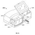
- FIG. 15illustrates a perspective view of a high flow therapy device in accordance with an embodiment of the present disclosure.
- FIG. 16illustrates a perspective view of the high flow therapy device of FIG. 15 showing internal components, in accordance with an embodiment of the present disclosure.
- FIG. 17illustrates a schematic view of the high flow therapy device of FIGS. 15 and 16 with a nasal interface and a patient in accordance with an embodiment of the present disclosure.
- FIG. 18illustrates a high flow therapy device including a nasal interface and a conduit in accordance with an embodiment of the present disclosure.
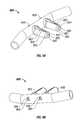
- FIGS. 19 and 20illustrate an enlarged view of a patient's upper airway and a nasal interface in accordance with two embodiments of the present disclosure.
- FIG. 21illustrates an example of a screen shot of a user interface of the high flow therapy device of FIGS. 15-17 in accordance with an embodiment of the present disclosure.
- FIGS. 22 and 23illustrate examples of a non-sealing respiratory interface in the form of a mouthpiece in accordance with embodiments of the present disclosure.
- FIG. 24illustrates a mouthpiece of FIG. 22 or 23 in use on a patient in accordance with an embodiment of the present disclosure.
- Nasal cannulamay be configured to deliver high-flow therapeutic gases to a patient's upper airway through the patient's nose.
- gasesmay include, for example, air, humidity, oxygen, therapeutic gases or a mixture of these, and may be heated or unheated.
- the cannulamay be useful for CPAP (continuous positive airway pressure) applications, which may be useful in the treatment of sleep apnea and in providing respiratory support to patients (e.g., after abdominal surgery), to alleviate snoring, or for other therapeutic uses.
- CPAPcontinuous positive airway pressure
- Nasal cannulainclude (or are adapted to facilitate the positioning of) one or more sensors adjacent or within one or more of the cannula's nasal inserts.
- the nasal cannulamay be configured so that at least a portion of one or more sensors is in place in one or both of a user's nares when the nasal cannula is operably worn by the user. This may be particularly helpful in evaluating the environment of the internal portion of the user's nose and/or the user's upper airway.
- the cannulais adapted so that it will not create a seal with the patient's nares when the cannula is in use.
- Nasal cannulainclude nozzles that are adapted to remain outside of a user's nares while the cannula is in use. Accordingly, the nozzles avoid sealing with the patient's nares while the cannula is in use.
- the nasal cannulainclude elongate extensions that are inserted into the user's nares to detect pressure in one or both nares.
- sensorsare provided adjacent or within both of the nasal cannula's nasal inserts. In various other embodiments, sensors are provided adjacent or within one or more elongate extensions that extend into the user's nares. In various embodiments, elongate extensions may be used in conjunction with nasal inserts or with nozzles.
- the use of sensorsmay be useful, for example, in monitoring environmental changes from one of the user's nares to the other. This information may be helpful, for example, in determining when the dominant flow of air changes from one of the user's nares to the other, which may affect the desired flow characteristics of therapy. Accordingly, data from each nare may provide information which may be useful in establishing or modifying the user's treatment regimen.
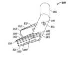
- FIG. 1A cannula 100 according to one embodiment of the invention is shown in FIG. 1 .
- the cannula 100includes a hollow, elongated tubular base 105 that includes a central portion 110 , a first end portion 115 , and a second end portion 120 .
- the first and second end portions 115 , 120may be angled relative to the central portion 110 as shown in FIG. 1 .
- the cannula 100includes a first inlet 117 adjacent the outer end of the first end portion 115 , and a second inlet 122 adjacent the second end portion 120 (in other embodiments, the cannula may include only one such inlet).
- the cannula 100further comprises a pair of hollow, elongated, tubular nasal inserts (e.g., nasal catheters) 125 , 130 that extend outwardly from the nasal cannula's base portion 105 and that are in gaseous communication with the base portion's interior.
- the respective central axes of the nasal inserts 125 , 130are substantially parallel to each other, and are substantially perpendicular to the central axis of the central portion 110 of the nasal cannula's base portion 105 .
- the cannuladefines at least one conduit that is adapted to guide a sensor so that the sensor is introduced adjacent or into the interior of the cannula so that, when the cannula is being operably worn by a user, the environment being monitored by the sensor reflects that of the internal portion of the user's nose and/or the user's upper airway.
- a usermay temporarily insert the sensor into or through the conduit to determine correct settings for the cannula system, and then may remove the sensor after the correct settings have been achieved.
- the sensormay be left in place within the conduit for the purpose of monitoring data within (or adjacent) the cannula over time (e.g., for purposes of controlling the user's therapy regimen).
- the sensormay be positioned adjacent an outlet of the conduit.
- the sensormay be connected (e.g., via electrical wires) to a computer and/or a microprocessor that is controlling the flow of respiratory gases into the cannula.
- the computermay use information received from the sensor to control this flow of gas and/or other properties of the system, or may issue an alarm if the information satisfies pre-determined criteria (e.g., if the information indicates potentially dangerous conditions within the patient's airway or if the system fails to operate correctly).
- At least one of the cannula's conduits 850is defined by, and extends within, a side wall of the cannula 800 .
- the conduitmay be disposed within an interior passage defined by the cannula.
- one or more of the conduitsmay be defined by a tube that is attached immediately adjacent an interior surface of the cannula (e.g., adjacent an interior surface of the cannula's base portion, or an interior surface of one of the cannula's nasal inserts).
- the cannula's conduitsare preferably adapted for: (1) receiving a flow of gas at one or more inlets that are in communication with the conduit, and (2) guiding this flow of gas to an outlet in the cannula.
- one or more of the inletsis defined within an exterior portion of one of the cannula's nasal inserts.
- each of the cannula's conduit outletsis located at the end of a respective elongate, substantially tubular, outlet member 135 , 140 .
- the cannula 100includes a first outlet member 135 that is substantially parallel to the cannula's first nasal insert 125 .
- the first outlet member 135 and the first nasal insert 125may be positioned on opposite sides of the nasal cannula's base 105 as shown in FIG. 1 .
- the cannula 100includes a second outlet member 140 that is substantially parallel to the cannula's second nasal insert 130 .
- the second outlet member 140 and second nasal insert 130are also preferably positioned on opposite sides of the nasal cannula's base 105 .
- a sensore.g., a pressure, temperature, or O 2 . sensor
- a sensoris provided adjacent at least one of (and preferably each of) the cannula's outlets and is used to measure the properties of gas from that outlet.
- accessory tubingis used to connect each outlet 135 , 140 with at least one corresponding sensor (and/or at least one external monitoring device) that may, for example, be spaced apart from the cannula 100 .
- one or more sensorsare provided within the conduit, and used to measure the properties of gas accessed through the conduit.
- information from each sensormay be relayed to a control system outside the cannula via, for example, an electrical wire that extends from the sensor and through the outlet 135 , 140 of the conduit in which the sensor is disposed.
- each of the cannula's conduitsmay extend: (1) from the inlets 152 , 154 ; (2) through, or adjacent, a side wall of one of the cannula's nasal inserts 125 , 130 ; (3) through, or adjacent, a side wall of the cannula's base 105 ; and (4) to an outlet 135 , 140 that is defined within, or disposed adjacent, the cannula's base 105 .
- the conduitcomprises a substantially tubular portion that is disposed adjacent an interior surface of the cannula's base.
- the cannula 200includes at least one sensor 245 that is integrated into an exterior portion of the cannula 200 (e.g., within a recess 223 formed within an exterior surface of one of the cannula's nasal inserts 225 , 230 ).
- information from the sensor 245may be relayed to a control system outside the cannula 200 via an electrical wire 246 that extends from the sensor 245 , through a conduit, and out an outlet 235 , 240 in the conduit.
- the conduitextends through or adjacent an interior portion of a side wall of one of the cannula's nasal inserts 225 , 230 and/or through or adjacent an interior portion of a side wall of the cannula's base 205 .
- At least one sensor 245is fixedly attached to the cannula 100 so that it may not be easily removed by a user. Also, in particular embodiments, at least one sensor 245 is detachably connected adjacent the cannula 100 so that the sensor 245 may be easily detached from (and, in certain embodiments, reattached to) the cannula 100 .
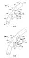
- the cannula 1000includes a hollow, elongated tubular base 1005 that includes a central portion 1010 , a first end portion 1015 , and a second end portion 1020 .
- the first and second end portions 1015 , 1020may be angled relative to the central portion 1010 , as shown in FIG. 10 .
- the cannula 1000includes a first inlet 1017 adjacent the outer end of the first end portion 1015 , and a second inlet 1022 adjacent the outer end of the second end portion 1020 .
- the cannula 1000further comprises a pair of hollow, elongated, tubular nozzles (a first nozzle 1026 and a second nozzle 1031 ) that extend outwardly from the nasal cannula's base portion 1005 .
- the respective central axes of the nozzles 1026 , 1031are substantially parallel to each other and are substantially perpendicular to the central axis of the central portion 1010 of the nasal cannula's base portion 1005 .
- the nozzles 1026 , 1031define conduits that are in gaseous communication with the interior of the cannula's base portion 1005 .
- the first and second nozzles 1026 , 1031are adapted to be positioned outside of a user's nares while the cannula is in use.
- the nozzles 1026 , 1031each define a respective nozzle outlet.
- the first nozzle 1026defines a first nozzle outlet 1083
- the second nozzle 1031defines a second nozzle outlet 1084 .
- each of the nozzle's outlets 1083 , 1084is positioned to direct a focused flow of gas into a corresponding one of the user's nares.
- the nasal cannula 1200may include a single nozzle 1227 that defines a conduit or air passageway that is in gaseous communication with an interior portion of the cannula's base portion 1205 .
- the nozzle 1227extends outwardly from the cannula's base portion 1205 and has an oblong, or elliptical, cross-section.
- the nozzle 1227is shaped to deliver a focused flow of gas simultaneously into both of a user's nares when the cannula 1200 is in use.
- the nasal cannulaincludes one or more elongate extensions that are adapted for insertion into one or more of the user's nares.
- the nasal cannula 1000may include multiple elongate extensions (for example a first elongate extension 1070 and a second elongate extension 1072 ) that are long enough to allow each of the elongate extensions 1070 , 1702 to be inserted into a respective one of the user's nares while the nasal cannula 1000 is in use.
- each of the elongate extensions 1070 , 1072may have a central axis that runs substantially parallel to the central axis of a corresponding nozzle 1026 , 1031 .
- a first elongate extension 1070has a central axis that lies substantially parallel to and below the central axis of a corresponding first nozzle 1026 , when the nasal cannula is operatively positioned adjacent a user's nares.
- a second elongate extension 1072has a central axis that lies substantially parallel to and below the central axis of a corresponding second nozzle 1031 , when the nasal cannula 1000 is operatively positioned adjacent a user's nares.
- the elongate extensionsmay lie within, and extend outwardly from, their corresponding nozzles 1070 , 1072 .
- FIG. 12illustrates an exemplary nasal cannula 1200 having multiple elongate extensions (a first elongate extension 1270 and a second elongate extension 1272 ), which both lie substantially below a single nozzle 1227 when the nasal cannula 1200 is in an operative position adjacent the user's nose.
- the central axes of the first and second elongate extensions 1270 , 1272may be substantially parallel to the central axis of the nozzle 1227 .
- one or both of the elongate extensions 1270 , 1272may lie within the nozzle 1227 .
- a distal end of each of the elongate extensions 1270 , 1272may extend beyond a distal end of the nozzle 1227 .
- the nasal cannulaincludes one or more sensors that are adapted to measure gas data (e.g., gas pressure) within the user's nares while the nasal cannula is in use.
- the nasal cannula 1000 shown in FIG. 10may include a sensor positioned adjacent the distal end of one or both of the first and second elongate extensions 1070 , 1072 .
- each elongate extensionmay be adapted to: (1) support a sensor adjacent (e.g., at) the distal end of the elongate extension; and (2) support a wire that is simultaneously connected to the sensor and a control mechanism that is adapted to adjust the properties of gas flowing through the cannula 1000 .
- the elongate extensionsdefine conduits.
- the sensor(s)may be positioned within the interior or exterior of the elongate extensions and information from the sensor(s) may be relayed to a control system via a wire extending through a conduit (for example, conduit 1023 of FIG. 10 ) or passageway defined by each of the elongate extensions.
- the conduit 1023is shaped similarly to the nasal cannula's base portion 1005 , and lies substantially below the base portion 1005 when the nasal cannula 1000 is operatively in use.
- the conduit 1023is positioned within the base portion 1005 such that the first and second elongate extensions 1070 , 1072 lie within, and extend outwardly from, the respective first and second nozzles 1026 , 1031 .
- each elongate extensiondefines a respective conduit that can serve as an air passageway.
- each conduitis adapted to provide a passage that permits gaseous communication between a user's nares and a control system or other device for measuring and adjusting the properties of the air.
- a sensormay be positioned at the control box to measure the properties (e.g., pressure) of air in the user's nares.
- the elongate extensionsdefine a conduit that serves both as an air passageway as well as a conduit for allowing a wire to pass from a sensor positioned adjacent the tip of the elongate extension to the control system or other device.
- one or more sensorsmay be positioned to measure gas data within an interior portion of one of the nasal cannula's conduits, or to measure gas data adjacent an exterior portion of the cannula.
- one or more sensorsmay be, for example, positioned adjacent an interior or exterior surface of the cannula.
- one or more of the cannula's sensorsis adapted to monitor one or more of the following types of data within the cannula's conduits, or adjacent the cannula's exterior surface (e.g., adjacent a side portion, or distal end of, one of the cannula's nasal inserts): (1) gas pressure; (2) gas flow rate; (3) carbon dioxide content; (4) temperature; (5) moisture level; and/or (6) oxygen content.
- the cannulamay be configured for sensing absolute pressure within, or adjacent, a particular portion of the cannula.
- the cannulamay be configured to measure the difference between the pressure at two different locations within the cannula. This may be done, for example, by providing two separate sensors (e.g., that are positioned in different locations within one of the cannula's conduits), or by providing two physically distinct gas intake conduits, each of which is adapted for routing gas from a different location within the cannula.
- two separate sensorse.g., that are positioned in different locations within one of the cannula's conduits
- two physically distinct gas intake conduitseach of which is adapted for routing gas from a different location within the cannula.
- the first inlet 152may be connected to a first intake conduit that is adapted for routing gas to a first sensor
- the second inlet 154may be connected to a physically separate second intake conduit that is adapted for routing gas to a second pressure sensor.
- Information from the first and second sensorsmay then be used to calculate the difference in pressure between the first and second inlets 152 , 154 .
- a differential pressure sensormay be used.
- Suitable sensors for use with various embodiments of the inventioninclude electronic and optical sensors.
- suitable sensorsmay include: (1) Disposable MEM Piezoelectric sensors (e.g., from Silex Microsensors); (2) light-based sensors such as a McCaul O 2 sensor—see U.S. Pat. No. 6,150,661 to McCaul; and (3) Micro-pressure sensors, such as those currently available from Honeywell.
- one or more of the nasal cannula's nasal inserts 425 , 430defines one or more recesses 423 (e.g., grooves, semicircular recesses, or other indentations or conduits) that extend along a length of the nasal insert's exterior surface.
- recesses 423e.g., grooves, semicircular recesses, or other indentations or conduits
- At least one of these recesses 423is an elongate groove that extends from adjacent a distal surface of the nasal insert 325 , 330 , 425 , 430 and past the midpoint between: (1) the nasal insert's distal surface and (2) the portion of the nasal insert 425 , 430 that is immediately adjacent the nasal cannula's base portion 305 , 405 .
- each groove 423extends substantially parallel to the central axis of its respective nasal insert 425 , 430 .
- At least one of the nasal cannula's nasal inserts 425 , 430is configured so that when the nasal inserts 425 , 430 are operatively positioned within a user's nares, the nasal inserts do not form an airtight seal with the user's nares. This may be due, for example, to the ability of air to flow adjacent the user's nare through recesses 423 in the nasal inserts 425 , 430 when the user is wearing the nasal cannula.
- FIGS. 5-8depict additional embodiments of the invention that are configured so that when the cannula's nasal inserts are operatively positioned adjacent (e.g., partially within) the user's nares, the nasal inserts do not form a seal with the user's nares.
- the nasal insertsdo not form a seal with the user's nares.
- At least one (and preferably both) of the cannula's nasal inserts 525 , 530comprise an inlet 555 (which may, for example, be substantially tubular), and one or more flange portions 560 , 561 that are adapted to maintain a physical separation between an exterior side surface of the inlet 555 and a user's nare when the nasal insert 525 , 530 is inserted into the user's nare.
- each of the cannula's nasal inserts 525 , 530includes a substantially tubular inlet 555 and a pair of co-facing, elongated flanges 560 , 561 that each have a substantially C-shaped cross section.
- these C-shaped flanges 560 , 561cooperate with a portion of the exterior of the inlet 555 to form a substantially U-shaped channel (which is one example of a “nasal lumen”) through which ambient air may flow to and/or from a user's nasal passages when the cannula 500 is operatively in place within the user's nares.
- respiratory gasis free to flow into the user's nose through the inlet 555
- ambient airis free to flow into and out of the user's nose through a passage defined by: (1) the flanges 560 , 561 ; (2) the exterior side surface of the inlet 555 that extends between the flanges 560 , 561 ; and (3) an interior portion of the user's nose.
- airmay flow to and/or from a user's nose through this passage when the cannula 500 is operatively in place within the user's nares.
- a pathway(e.g., a semicircular pathway) may be provided adjacent the interior end of this U-shaped channel, which may act as a passageway for gas exhaled and inhaled through the U-shaped channel.
- FIG. 5may have many different structural configurations.
- the respiratory gas inlets of the cannula's nasal inserts 655may be in the form of a tube having an irregular cross section (e.g., a substantially pie-piece-shaped cross section) rather than a circular cross section.
- the respiratory gas inlets of the cannula's nasal inserts 755may be in the form of a tube having a substantially half-circular cross section rather than a circular cross section.
- each of the flanges 660 , 661has a relatively short, substantially C-shaped cross section and the distal ends of flanges 660 , 661 are spaced apart from each other to form a gap.
- each of the flanges 760 , 761may have a relatively long, substantially C-shaped cross section and the distal ends of the flanges 760 , 761 may be positioned immediately adjacent each other.
- a separation 763(e.g., a slit, such as an angular slit) is provided between the flanges 760 , 761 .
- Thismay allow the flanges 760 , 761 to move relative to each other and to thereby conform to the nare in which the nasal insert is inserted.
- the cross section of the nasal insertsis substantially as that shown in FIG. 7 , except that no separation 763 is provided within the semi-circular flange portion.
- a substantially semi-circular portion of the exterior of the air inletcooperates with a substantially semi-circular portion of the flange portion to form an exterior having a contiguous, substantially circular cross section.
- FIGS. 8A-8COne such embodiment is shown in FIGS. 8A-8C .
- respiratory gasmay flow into the user's nose through passageways 881 (e.g., a portion of which may be defined by a corresponding respiratory gas inlet 855 ) that extend through each of the cannula's nasal inserts 825 , 830 .
- a pathway 885 of substantially semi-circular cross sectionextends between the distal end of each nasal insert 825 , 830 to a substantially semicircular outlet 865 defined within the cannula's base 805 .
- the usermay inhale and exhale gas through this pathway 885 .
- a conduit 850is provided in each of the cannula's nasal inserts 825 , 830 (see FIG. 8C ).
- Each of these conduits 850may be adapted to: (1) receive gas from the interior of a corresponding pathway 885 and/or from adjacent the exterior of one of the cannula's nasal inserts 825 , 830 , and (2) guide the gas out of a corresponding outlet 835 , 840 in the cannula 800 .
- one or more sensorsmay be disposed within, or adjacent, the conduit 850 and used to assess one or more attributes of gas flowing through or adjacent the conduit 850 .
- the embodiments of the invention shown in FIGS. 4-8 and related embodimentsmay have utility with or without the use of sensors or sensor conduits.
- the various nasal insertsmay be configured to be disposed in any appropriate orientation within the user's nares when the cannula is operably positioned within the user's nares.
- the cannulamay be positioned so that the cannula's nasal lumen is immediately adjacent, or so that it faces anterior-laterally away from, the user's nasal spine.
- the cannula 900 and corresponding sensormay be adapted so that a tube inlet 970 , 972 for at least one sensor (or the sensor itself) is maintained adjacent, and spaced a pre-determined distance apart from, the distal end of a respective nasal insert 925 , 930 .
- the sensoror sensor intake inlet
- the sensormay be spaced apart from the rest of the nasal cannula 900 adjacent one of the nasal cannula's outlet openings.
- the first and second nozzles 1026 , 1031 of the nasal cannulaare configured to remain outside of the user's nares while the cannula is in use.
- the nozzlesmay be of a length such that, when the cannula is in use, the distal ends of the nozzles 1026 , 1031 lie adjacent, but outside, the user's nares. By preventing insertion of the nozzles 1026 , 1031 into the nares, sealing of the nares can be avoided.
- FIG. 10may be understood from FIG.
- each nozzle 1326 , 1331when the nasal cannula is in an operative position adjacent the user's nares, an outlet portion (and distal end) of each nozzle 1326 , 1331 is spaced apart from, and substantially in-line (e.g., substantially co-axial) with, a corresponding one of the patient's nares.
- the outlet of each nozzlewhen the nasal cannula is operatively in use, the outlet of each nozzle is spaced apart from the patient's nares and each nozzle is positioned to direct a focused flow of gas into a particular respective one of the user's nares.
- a stop 1190may extend outwardly from the base portion 1105 of the nasal cannula.
- the stop 1190lies in between the first and second nozzles 1126 , 1131 and defines a central axis that runs substantially parallel to the respective central axes of the nozzles 1126 , 1131 .
- the stop 1190in some embodiments, may extend outwardly from the nasal cannula's base portion 1105 a length greater than that of the nozzles 1126 , 1131 . In this manner, the stop 1190 prevents the nozzles 1126 , 1131 from being inserted into the user's nares when the nasal cannula 1100 is in use.
- the stop 1190may be positioned so that when the nasal cannula 1100 is in use, the stop is designed to engage the columella of the user's nose and thereby prevent the nozzles 1126 , 1131 from being inserted into the user's nares.
- the first and second nozzles 1126 , 1131are positioned on either side of the stop 1190 so that when the nasal cannula 1100 is operatively in use, the each nozzle 1126 , 1131 will be spaced apart from a respective particular one of the patient's nares and will be positioned to direct a focused flow of gas into that particular nare by, for example, being positioned so that the outlet (and distal end) of each nozzle (first outlet 1183 and second outlet 1184 ) is substantially in-line (e.g., substantially co-axial) with, a corresponding one of the patient's nares.
- the nasal cannula 1200may include only a single nozzle 1227 .
- the nozzle 1227in various embodiments, has an oblong or substantially elliptical cross-section. In these embodiments, the major axis of the ellipse runs substantially parallel to the central axis of the base portion 1205 of the nasal cannula. In one embodiment, the nozzle 1227 is wide enough to allow air to flow into both of a user's nares when the nasal cannula is in use.
- the width of the nozzle 1227(e.g., a length defined by the major axis of the nozzle's elliptical cross section) may be approximately equal to (or greater than) the total width of the user's nares.
- a first lateral side 1430 of the nozzle outlet 1429is spaced apart from, and adjacent, a user's first nare
- a second lateral side 1430 of the nozzle 1429is spaced apart from, and adjacent, the user's second nare.
- the nozzle 1422is configured to direct a focused flow of gas simultaneously into each of the user's nares.
- the nozzle 1227when the nozzle is of a width approximately equal to (or greater than) the total width of the user's nares, and other widths, the nozzle 1227 is sufficiently wide to prevent the nozzle 1227 from being inserted into a user's nare, thus preventing sealing of the nasal cannula with the nare.
- the cannula's single nozzlemay have a different cross-section that is not oblong or elliptical.
- the nozzlemay have a substantially circular cross-section, with a diameter that is wide enough to allow air to flow into both of a user's nares when the cannula is in use, while simultaneously being wide enough to prevent insertion into a single nare.
- the nasal cannulamay have more than one nozzle, each having a substantially oblong cross section and a width that prevents insertion into each of a user's nares.
- one or more of the cannula's elongate extensionshas a diameter that is adapted to prevent sealing with the user's nares.
- the elongate extension(s)may have a diameter that is substantially narrower than a user's nares, so that sealing is avoided.
- the elongate extension(s)may include features such as grooves or recesses, as described above, to prevent sealing when inserted into a user's nare(s).
- a physician or technicianmay have a patient use the cannula for a brief period of time, while the physician or technician monitors information received from the cannula's various sensors, or the information may be recorded for later analysis. The physician or technician may then use this information to adjust the structure or operation of the cannula until the cannula's sensors indicate that the patient's upper airway environment satisfies certain conditions.
- the cannula's sensorsmay be used to monitor conditions within the patient's upper airway over time.
- the cannula's sensorsmay be connected to a control system that will automatically alter or modify the flow of therapeutic gas into the cannula if information from the sensor indicates undesirable conditions within the patient's upper airway.
- the sensoris connected to a control system that issues an alarm if information from the cannula's sensors indicate undesirable conditions within the patient's airway.
- FIGS. 13 and 14depict various embodiments of nasal cannulas being used on a patient.
- a nasal cannulais used on a young or small infant for high flow therapy.
- a nasal cannula similar to that shown in FIG. 10can be used.
- first and second elongate extensions 1370 , 1372are inserted into the patient's nares, while corresponding first and second nozzles 1326 , 1331 remain adjacent and external to the patient's nares.
- nasal cannula 14depicts one embodiment of a nasal cannula in use on a patient.
- a nasal cannulasuch as that shown in FIG. 12 can be used.
- a nasal cannula having a single nozzle 1427can be used, in which the nozzle is sized and shaped (e.g., is elliptical and/or wider than a patient's nare) to prevent insertion into the patient's nares.
- nasal cannula having nasal insertsas described throughout, can be used. In these embodiments, the nasal inserts are inserted into the user's nares while the cannula is in use.
- Nasal cannula according to embodiments of the inventioncan be used on a variety of patients.
- High flow therapy device 2000is configured for use with a non-sealing respiratory interface, such as cannula 100 , for example, to deliver gas to a patient.
- high flow therapy device 2000is able to heat, humidify, and/or oxygenate a gas prior to delivering the gas to a patient.
- embodiments of high flow therapy device 2000are able to control and/or adjust the temperature of the gas, the humidity of the gas, the amount of oxygen in the gas, the flow rate of the gas and/or the volume of the gas delivered to the patient.
- High flow therapy device 2000is shown in FIG. 15 including a housing 2010 , a humidity chamber 2020 (e.g., vapor generator), a user interface 2030 , a gas inlet port 2040 and a gas outlet port 2050 .
- a microprocessor 2060 , an air inlet port 2070 , a blower 2080 , an oxygen inlet 2090 and a proportional valve 2100are illustrated in FIG. 16 .
- a non-sealing respiratory interface(such as a nasal cannula illustrated in FIGS. 1-14 (e.g., 100 or 1200 and hereinafter referred to as 100 ), is configured to mechanically cooperate with gas outlet port 2050 to supply a patient with gas.
- a heating element 2110is shown schematically in FIG. 17 (and is hidden from view by humidity chamber 2020 in FIG. 15 ) is in electrical communication with microprocessor 2060 (which is included on printed circuit board (“PCB”)), via wire 2112 , for instance, and is capable of heating a liquid (e.g., water) within humidity chamber 2020 to create a gas.
- Non-sealing respiratory interface 100is configured to delivery this gas to a patient.
- a sensor 2120 or transducershown in FIG. 20
- a conduit 2130extends between the upper airway of the patient and sensor 2120 ( FIG. 19 , sensor 2120 is not explicitly shown in FIG. 19 , but may be disposed adjacent microprocessor 2060 ). In another embodiment, sensor 2120 is disposed at least partially within the upper airway of the patient with a wire 2122 relaying signals to microprocessor 2060 ( FIGS. 18 and 20 ).
- a liquide.g., water
- Heating element 2110heats the liquid to create a vapor or gas. This vapor heats and humidifies the gas entering humidity chamber 2020 through gas inlet port 2040 .
- the heated and humidified vaporflows through gas outlet port 2050 and through non-sealing respiratory interface 100 .
- sensor 2120collects data for the measurement of the patient's respiration rate, tidal volume and minute volume. Further, based on measurements taken by sensor 2120 and relayed to microprocessor 2060 , microprocessor 2060 is able to adjust the temperature of the gas, the humidity of the gas, the amount of oxygen of the gas, flow rate of the gas and/or the volume of the gas delivered to the patient.
- microprocessor 2060may, for example, adjust the speed of blower 2080 and/or oxygen proportional valve 2100 so that sufficient pressure levels are maintained.
- sensor 2120may be used to monitor respiratory rates, and microprocessor 2060 may signal alarms if the respiratory rate exceeds or falls below a range determined by either microprocessor 2060 or set by an operator. For example, a high respiratory rate alarm may alert the operator and may indicate that the patient requires a higher flow rate and/or higher oxygen flow.
- thermocouples 2200 and 2202are illustrated, which detect the temperature entering and leaving a circuit 2210 disposed between respiratory interface 100 and gas outlet port 2050 .
- a second heating element 2114(or heater) (e.g., a heated wire) may be disposed adjacent air outlet port 2050 to further heat the gas. It is also envisioned that second heating element 2114 is disposed within circuit 2210 .
- Thermocouples 2200 and 2202are in communication with microprocessor 2060 and may be used to adjust the temperature of heating element 2110 and second heating element 2114 .
- a feedback loopmay be used to control the temperature of the delivered gas, as well as to control its humidity and to minimized rainout.
- FIG. 16illustrates an embodiment of circuit 2210 including conduit 2130 co-axially disposed therein, in accordance with an embodiment of the present disclosure.
- blower 2080is used to draw in ambient air from air inlet port 2070 and force it through an air flow tube 2140 , through gas inlet port 2040 , through humidity chamber 2020 and through gas outlet port 2050 towards non-sealing respiratory interface 100 .
- Blower 2080is configured to provide a patient (e.g., an adult patient) with a gas flow rate of up to about 60 liters per minute. In a particular embodiment, it is envisioned that blower 2080 is configured to provide a patient with a gas flow rate of up to about 40 liters per minute.
- an air intake filter 2072(shown schematically in FIG. 17 ) may be provided adjacent air inlet port 2070 to filter the ambient air being delivered to the patient.
- air intake filter 2072is configured to reduce the amount of particulates (including dust, pollen, fungi (including yeast, mold, spores, etc.) bacteria, viruses, allergenic material and/or pathogens) received by blower 2080 . Additionally, the use of blower 2080 may obviate the need for utilization of compressed air, for instance. It is also envisioned that a pressure sensor is disposed adjacent air intake filter 2072 (shown schematically in FIG. 17 ), which may be capable of determining when air intake filter 2072 should be replaced (e.g., it is dirty, it is allowing negative pressure, etc).
- oxygen inlet 2090is configured to connect to an external source of oxygen (or other gas) (not explicitly shown) to allow oxygen to pass through high flow therapy device 2000 and mix with ambient air, for instance.
- Proportional valve 2100being in electrical communication with microprocessor 2060 , is disposed adjacent oxygen inlet 2090 and is configured to adjust the amount of oxygen that flows from oxygen inlet 2090 through an oxygen flow tube 2150 .
- oxygen flowing through oxygen flow tube 2150mixes with ambient air (or filtered air) flowing through air flow tube 2140 in a mixing area 2155 prior to entering humidity chamber 2020 .
- sensor 2120measures both inspiration pressure and expiration pressure of the patient.
- conduit 2130delivers the pressure measurements to sensor 2120 (not explicitly shown in FIGS. 18 and 19 ), which may be disposed adjacent microprocessor 2060 .
- sensor 2120is position adjacent the patient's upper airway and includes wire 2122 to transmit the readings to microprocessor 2060 .
- cliniciansdo not desire ambient air to enter a patient's upper airway.
- the inspiration and expiration pressure readings from within (or adjacent) the upper airwaymay be compared ambient air pressure. That is, a patient may be inhaling gas at a faster rate than the rate of gas that high flow therapy device 2000 is delivering to the patient. In such a circumstance (since respiratory interface 100 is non-sealing), in addition to breathing in the supplied gas, the patient also inhales ambient air.
- microprocessor 2060 of high flow therapy device 2000is able to adjust various flow parameters, such as increasing the flow rate, to minimize or eliminate the entrainment of ambient air.
- FIG. 21illustrates an example of a screen shot, which may be displayed on a portion of user interface 2030 .
- the crest of the sine-like waverepresents expiration pressure and the valley represents inspiration pressure.
- Microprocessor 2060may be configured to automatically adjust an aspect (e.g., increasing the flow rate) of the gas being supplied to the patient by high flow therapy device 2000 to overcome the entrainment of ambient air. Further, microprocessor 2060 may convey the pressure readings to the operator who may then input settings to adjust the flow rate to minimize entrainment of ambient air or to maintain a level of pressure above the ambient air pressure.
- lowering the flow rates during expirationmay also minimize oxygen flow through high flow therapy device 2000 .
- Such lowering of a flow ratemay also minimize entry of oxygen into a closed environment, such as the patient room or the interior of an ambulance, where high levels of oxygen might be hazardous.
- conduit 2130may be used as a gas analyzer which may be configured to take various measurements (e.g., percent of oxygen, percentage of carbon dioxide, pressure, temperature, etc.) of air in or adjacent a patient's upper airway.
- a gas portmay be disposed adjacent housing 2010 to communicate with exterior of housing 2010 . It is envisioned that the gas port is configured to allow the use of external devices to measure various gas properties (e.g., percent oxygen and pressure). Additionally, the gas port may be used for external verification of gas values. Further, a communications port 2300 , shown in FIG. 16 , may be included to facilitate connection with an external device, such as a computer, for additional analysis, for instance. Further, communications port 2300 enables connection with another device, enabling data to be monitored distantly, recorded and/or reprogrammed, for example.
- an external devicesuch as a computer
- a directional valve 2160 and/or a sample pump 2170may also be included to facilitate sampling the gas for analysis. More specifically, in a particular embodiment, sample pump 2170 is capable of moving a quantity of gas towards the gas analyzer. As shown schematically in FIG. 17 , the gas sample can be taken from a patient's upper airway via conduit 2130 or from mixing area 2155 via a sample line 2180 and a sample port 2182 ( FIG. 16 ).
- Directional valve 2160may be controlled by microprocessor 2060 to direct a gas sample from either location (or a different location such as after the gas is heated). The gas analyzer can compare measurements of the gas sample(s) with predetermined measurements to ensure high flow therapy device 2000 is working optimally. It is further envisioned that sample pump 2170 may be configured to pump a gas or liquid towards the patient to provide the patient with an additional gas, such as an anesthetic, for instance and/or to clean or purge conduit 2130 .
- an additional gassuch as an anesthetic
- the present disclosurealso relates to methods of supplying a patient with gas.
- the methodincludes providing high flow therapy device 2000 , as described above, for example, heating the gas, and delivering the gas to the patient.
- high flow therapy device 2000includes microprocessor 2060 , heating element 2110 disposed in electrical communication with microprocessor 2060 , non-sealing respiratory interface 100 configured to deliver gas to the patient and sensor 2120 disposed in electrical communication with microprocessor 2060 and configured to measure pressure in the upper airway of the patient.
- the method of this embodimentmay be used, for instance, to provide a patient with respiratory assistance.
- Blower 2080may also be included in high flow therapy device 2000 of this method. Blower 2080 enables ambient air to enter high flow therapy device 2000 (e.g., through filter 2072 ) and be supplied to the patient.
- high flow therapy deviceis portable, as it does not need an external source of compressed air, for example.
- high flow therapy device 2000includes heating element 2110 and non-sealing respiratory interface 100 .
- a patientmay be provided with heated and/or humidified air (e.g., at varying flow rates) to help minimize respiratory infections of the patient.
- heated and/or humidified aire.g., at varying flow rates
- such a methodmay be used in connection with certain filters 2072 to help prevent patients from obtaining various conditions associated with inhaling contaminated air, such as in a hospital.
- providing appropriately warmed and humidified respiratory gasesoptimizes the motion of the cilia that line the respiratory passages from the anterior third of the nose to the beginning of the respiratory bronchioles, further minimizing risk of infection.
- supplemental oxygenmay add to this effect.
- Microprocessor 2060 in connection with sensor 2120may also be included with high flow therapy device 2000 of this method for measuring and controlling various aspects of the gas being delivered to the patient, for instance, as described above.
- a further method of the present disclosurerelates to another way of supplying a patient with gas.
- the present methodincludes providing high flow therapy device 2000 including heating element 2110 , non-sealing respiratory interface 100 , blower 2080 , air inlet port 2070 configured to enable ambient air to flow towards blower 2080 and filter 2070 disposed in mechanical cooperation with air inlet port 2070 and configured to remove pathogens from the ambient air.
- High flow therapy device 2000 of this methodmay also include microprocessor 2060 and sensor 2120 .
- High flow therapy device 2000to treat headaches, upper airway resistance syndrome, obstructive sleep apnea, hypopnea and/or snoring.
- High flow therapy device 2000may be set to provide sufficient airway pressure to minimize the collapse of the upper airway during inspiration, especially while the use is asleep.
- HFTmay be more acceptable to children and other who may not tolerate traditional CPAP therapy which requires a sealing interface. Early treatment with HFT may prevent the progression of mild upper airway resistance syndrome to more advanced conditions such as sleep apnea and its associated morbidity.
- gasmay be delivered to patient at a temperature of between about 32° C. and about 40° C. (temperature in the higher end of this range may provide a more rapid response) and having at least about 27 milligrams of water vapor per liter. More specifically, it is envisioned that a gas having a water vapor content of between about 33 mg/liter and about 44 mg/liter may be used. It is envisioned that the gas being delivered to the patient includes moisture content that is similar to that of a typical exhaled breath. In an embodiment, the flow rates of this heated and humidified air are sufficient to prevent/minimize entrainment of ambient air into the respired gas during inspiration, as discussed above. The inclusion of an increased percentage of oxygen may also be helpful. Further, the gas may be delivered to the patient using non-sealing respiratory interface 100 .
- High flow therapy device 2000 used in these methodsincludes heating element 2110 and non-sealing respiratory interface 100 .
- Microprocessor 2060 and sensor 2120may also be included in high flow therapy device 2000 of this method.
- blower 2080in accordance with a disclosed embodiment, enables high flow therapy device 2000 to be portable, as it does not need to be connected to an external source of compressed air or oxygen.
- high flow therapy device 2000 of this methodis able to be used, relatively easily, in a person's home, a doctor's office, an ambulance, etc.
- the present disclosurealso relates to a method of delivering respiratory gas to a patient and includes monitoring the respiratory phase of the patient.
- Monitoring of a patient's respiratory phaseis enabled by taking measurements of pressure in a patient's upper airway. Additionally, respiratory phase may be determined by pressure with circuit 2210 or by monitoring activity of the phrenic nerve.
- Real-time pressure measurements(see sine-like wave in FIG. 21 , for example) enable real-time supplying of gas at different pressures to be delivered to the patient, or variable pressure delivery. For example, gas at a higher pressure may be delivered to the patient during inspiration and gas at a lower pressure may be delivered to the patient during expiration. This example may be useful when a patient is weak and has difficultly exhaling against an incoming gas at a high pressure. It is further envisioned that the pressure level of the gas being delivered to a patient is gradually increased (e.g., over several minutes) to improve patient comfort, for instance.
- mouthpiece 3000is illustrated in accordance with an embodiment of the present disclosure. As briefly described above, mouthpiece 3000 is an example of a respiratory interface of the present disclosure. Mouthpiece 3000 (illustrated resembling a pacifier) may be used to detect upper airway pressure of a patient.
- a first mouthpiece port 3010may be used to measure pressure inside mouthpiece 3000 through open end 3012 of first port.
- First mouthpiece port 3010may include an open-ended tube that communicates the pressure with mouthpiece 3000 to sensor 2120 (not explicitly shown in FIGS. 22-24 ) via first port conduit 2130 a .
- Sensor 2120may also be positioned within mouthpiece 3000 . It is envisioned that mouthpiece 3000 is at least partially filled with a gas or liquid, e.g., water.
- the pressure within mouthpiece 3000may help evaluate, record or otherwise use the pressure data for determining the strength of sucking or feeding, for instance.
- the timing of the sucking motion and the differential pressures in the mouthmay also be measured.
- the sucking pressuremay be used to help determine the strength of the sucking and may be used to evaluate the health of an infant, for instance.
- the measurement of oral-pharyngeal pressuremay also give data for setting or adjusting respiratory support therapy for the patient.
- a relatively short first mouthpiece port 3010may be used so that a bulb 3030 of mouthpiece 3000 acts as a pressure balloon.
- a relatively long first mouthpiece port 3010 having rigiditymay be used to help prevent closure of the tube from pressure from alveolar ridges or from teeth, for example.
- a second mouthpiece port 3020is configured to enter a patient's mouth or oral cavity when mouthpiece 3000 is in use and is configured to measure pressure within the oral cavity (upper airway pressure) through an open end 3022 of second mouthpiece port 3020 .
- Pressure from within the upper airwaye.g., measured adjacent the pharynx
- sensor 2120may be positioned adjacent mouthpiece 3000 . That is, the pressure communicated from with the upper airway to the patient's mouth is the pressure being measured.
- second mouthpiece port 3020extends beyond a tip of bulb 3030 to facilitate the acquisition of an accurate upper airway pressure measurement.
- a balloon 3040is shown adjacent a distal end 3024 of second port 3020 .
- a lumen of conduit 2130 bis in fluid communication with the internal area of balloon 3040 . Further, any forces against a wall of balloon 3040 are transmitted through the lumen towards sensor 2120 or transducer for control, observation or analysis.
- the pressure within the oral cavitymay vary during the phases of sucking and swallowing.
- High flow therapy device 2000 using mouthpiece 3000enables concurrent measurement of sucking pressure within mouthpiece 3000 and the pressure outside mouthpiece 3000 . This data may help determine treatment characteristics for respiratory support for infants, children or adults, e.g., unconscious adults.
- FIG. 1shows each nasal insert 125 , 130 having a two inlets 152 , 154
- one or more of the nasal inserts 125 , 130may have more or less than two inlets (and/or more or less than two sensors).
- sensor 2120may be situated or in communication with any area of the airway, and is not limited to sensing the environment of the anterior nares.
Landscapes
- Health & Medical Sciences (AREA)
- Pulmonology (AREA)
- Life Sciences & Earth Sciences (AREA)
- Emergency Medicine (AREA)
- Veterinary Medicine (AREA)
- Public Health (AREA)
- General Health & Medical Sciences (AREA)
- Animal Behavior & Ethology (AREA)
- Engineering & Computer Science (AREA)
- Hematology (AREA)
- Heart & Thoracic Surgery (AREA)
- Biomedical Technology (AREA)
- Anesthesiology (AREA)
- Otolaryngology (AREA)
- Measurement Of The Respiration, Hearing Ability, Form, And Blood Characteristics Of Living Organisms (AREA)
Abstract
Description
Claims (41)
Priority Applications (20)
| Application Number | Priority Date | Filing Date | Title |
|---|---|---|---|
| US11/638,981US8333194B2 (en) | 2005-09-12 | 2006-12-14 | High flow therapy device utilizing a non-sealing respiratory interface and related methods |
| US11/999,675US8522782B2 (en) | 2005-09-12 | 2007-12-06 | High flow therapy device utilizing a non-sealing respiratory interface and related methods |
| EP20070862634EP2101851A2 (en) | 2006-12-14 | 2007-12-07 | High flow therapy device utilizing a non-sealing respiratory interface and related methods |
| PCT/US2007/025085WO2008076230A2 (en) | 2006-12-14 | 2007-12-07 | High flow therapy device utilizing a non-sealing respiratory interface and related methods |
| CA002672292ACA2672292A1 (en) | 2006-12-14 | 2007-12-07 | High flow therapy device utilizing a non-sealing respiratory interface and related methods |
| AU2007334506AAU2007334506A1 (en) | 2006-12-14 | 2007-12-07 | High flow therapy device utilizing a non-sealing respiratory interface and related methods |
| US12/347,409US8333199B2 (en) | 2005-09-12 | 2008-12-31 | High flow therapy artificial airway interfaces and related methods |
| US13/717,572US9381317B2 (en) | 2005-09-12 | 2012-12-17 | High flow therapy artificial airway interfaces and related methods |
| US13/717,442US9427547B2 (en) | 2005-09-12 | 2012-12-17 | High flow therapy device utilizing a non-sealing respiratory interface and related methods |
| US14/016,042US11071464B2 (en) | 2005-09-12 | 2013-08-30 | High flow therapy device utilizing a non-sealing respiratory interface and related methods |
| US15/134,900US11458270B2 (en) | 2005-09-12 | 2016-04-21 | High flow therapy device utilizing a non-sealing respiratory interface and related methods |
| US15/185,130US10525221B2 (en) | 2005-09-12 | 2016-06-17 | High flow therapy artificial airway interfaces and related methods |
| US15/250,834US11833301B2 (en) | 2005-09-12 | 2016-08-29 | High flow therapy device utilizing a non-sealing respiratory interface and related methods |
| US17/373,082US20220031173A1 (en) | 2005-09-12 | 2021-07-12 | High flow therapy device utilizing a non-sealing respiratory interface and related methods |
| US17/387,538US11318267B2 (en) | 2006-09-12 | 2021-07-28 | High flow therapy device utilizing a non-sealing respiratory interface and related methods |
| US17/387,657US11717174B2 (en) | 2005-09-12 | 2021-07-28 | High flow therapy device utilizing a non-sealing respiratory interface and related methods |
| US17/387,752US11497407B2 (en) | 2005-09-12 | 2021-07-28 | High flow therapy device utilizing a non-sealing respiratory interface and related methods |
| US17/387,505US11406777B2 (en) | 2005-09-12 | 2021-07-28 | High flow therapy device utilizing a non-sealing respiratory interface and related methods |
| US17/871,109US20230084620A1 (en) | 2005-09-12 | 2022-07-22 | High flow therapy device utilizing a non-sealing respiratory interface and related methods |
| US17/883,573US11696992B2 (en) | 2005-09-12 | 2022-08-08 | High flow therapy device utilizing a non-sealing respiratory interface and related methods |
Applications Claiming Priority (6)
| Application Number | Priority Date | Filing Date | Title |
|---|---|---|---|
| US71677605P | 2005-09-12 | 2005-09-12 | |
| US75006305P | 2005-12-14 | 2005-12-14 | |
| US79271106P | 2006-04-18 | 2006-04-18 | |
| US11/520,490US20070107737A1 (en) | 2005-09-12 | 2006-09-12 | Nasal cannula |
| US85285106P | 2006-10-18 | 2006-10-18 | |
| US11/638,981US8333194B2 (en) | 2005-09-12 | 2006-12-14 | High flow therapy device utilizing a non-sealing respiratory interface and related methods |
Related Parent Applications (3)
| Application Number | Title | Priority Date | Filing Date |
|---|---|---|---|
| US11/520,490Continuation-In-PartUS20070107737A1 (en) | 2005-09-12 | 2006-09-12 | Nasal cannula |
| US11/520,490ContinuationUS20070107737A1 (en) | 2005-09-12 | 2006-09-12 | Nasal cannula |
| US13/717,572Continuation-In-PartUS9381317B2 (en) | 2005-09-12 | 2012-12-17 | High flow therapy artificial airway interfaces and related methods |
Related Child Applications (4)
| Application Number | Title | Priority Date | Filing Date |
|---|---|---|---|
| US99967505AContinuation-In-Part | 2005-09-12 | 2005-12-06 | |
| US11/999,675Continuation-In-PartUS8522782B2 (en) | 2005-09-12 | 2007-12-06 | High flow therapy device utilizing a non-sealing respiratory interface and related methods |
| US12/347,409Continuation-In-PartUS8333199B2 (en) | 2005-09-12 | 2008-12-31 | High flow therapy artificial airway interfaces and related methods |
| US13/717,442ContinuationUS9427547B2 (en) | 2005-09-12 | 2012-12-17 | High flow therapy device utilizing a non-sealing respiratory interface and related methods |
Publications (2)
| Publication Number | Publication Date |
|---|---|
| US20070175473A1 US20070175473A1 (en) | 2007-08-02 |
| US8333194B2true US8333194B2 (en) | 2012-12-18 |
Family
ID=39402140
Family Applications (2)
| Application Number | Title | Priority Date | Filing Date |
|---|---|---|---|
| US11/638,981Active2030-07-09US8333194B2 (en) | 2005-09-12 | 2006-12-14 | High flow therapy device utilizing a non-sealing respiratory interface and related methods |
| US13/717,442ActiveUS9427547B2 (en) | 2005-09-12 | 2012-12-17 | High flow therapy device utilizing a non-sealing respiratory interface and related methods |
Family Applications After (1)
| Application Number | Title | Priority Date | Filing Date |
|---|---|---|---|
| US13/717,442ActiveUS9427547B2 (en) | 2005-09-12 | 2012-12-17 | High flow therapy device utilizing a non-sealing respiratory interface and related methods |
Country Status (5)
| Country | Link |
|---|---|
| US (2) | US8333194B2 (en) |
| EP (1) | EP1979030A2 (en) |
| AU (1) | AU2006348403A1 (en) |
| CA (1) | CA2622734A1 (en) |
| WO (1) | WO2008060295A2 (en) |
Cited By (40)
| Publication number | Priority date | Publication date | Assignee | Title |
|---|---|---|---|---|
| US20110125052A1 (en)* | 2008-01-25 | 2011-05-26 | Salter Labs | Respiratory therapy system including a nasal cannula assembly |
| US20130104888A1 (en)* | 2005-09-12 | 2013-05-02 | Mergenet Medical, Inc. | High Flow Therapy Device Utilizing A Non-Sealing Respiratory Interface and Related Methods |
| KR101333195B1 (en) | 2012-09-03 | 2013-11-26 | 재단법인 아산사회복지재단 | Nasal interface for constant nasopharyngeal pressure during high-flow humidified oxygen therapy |
| US8770199B2 (en) | 2012-12-04 | 2014-07-08 | Ino Therapeutics Llc | Cannula for minimizing dilution of dosing during nitric oxide delivery |
| USD747792S1 (en)* | 2013-10-25 | 2016-01-19 | Fisher & Paykel Health Care Limited | Nasal cannula body |
| US20160367776A1 (en)* | 2005-09-12 | 2016-12-22 | Mergenet Medical, Inc. | High flow therapy device utilizing a non-sealing respiratory interface and related methods |
| US20160367779A1 (en)* | 2005-09-12 | 2016-12-22 | Mergenet Medical, Inc. | High flow therapy device utilizing a non-sealing respiratory interface and related methods |
| US9795756B2 (en) | 2012-12-04 | 2017-10-24 | Mallinckrodt Hospital Products IP Limited | Cannula for minimizing dilution of dosing during nitric oxide delivery |
| USD825053S1 (en)* | 2016-03-23 | 2018-08-07 | Fisher & Paykel Healthcare Limited | Nasal cannula |
| US10342942B2 (en) | 2013-03-15 | 2019-07-09 | Fisher & Paykel Healthcare Limited | Respiratory assistance device and method of controlling said device |
| US10589050B2 (en) | 2012-11-14 | 2020-03-17 | Fisher & Paykel Healthcare Limited | Zone heating for respiratory circuits |
| US10709866B2 (en) | 2014-05-13 | 2020-07-14 | Fisher & Paykel Healthcare Limited | Usability features for respiratory humidification system |
| US10751498B2 (en) | 2014-03-17 | 2020-08-25 | Fisher & Paykel Healthcare Limited | Medical tubes for respiratory systems |
| US10814091B2 (en) | 2013-10-24 | 2020-10-27 | Fisher & Paykel Healthcare Limited | System for delivery of respiratory gases |
| US10828482B2 (en) | 2013-12-20 | 2020-11-10 | Fisher & Paykel Healthcare Limited | Humidification system connections |
| US10905836B2 (en) | 2015-04-02 | 2021-02-02 | Hill-Rom Services Pte. Ltd. | Manifold for respiratory device |
| US10960167B2 (en) | 2015-09-09 | 2021-03-30 | Fisher & Paykel Healthcare Limited | Zone heating for respiratory circuits |
| US10974015B2 (en) | 2012-03-15 | 2021-04-13 | Fisher & Paykel Healthcare Limited | Respiratory gas humidification system |
| US11058844B2 (en) | 2012-12-04 | 2021-07-13 | Fisher & Paykel Healthcare Limited | Medical tubes and methods of manufacture |
| USD926311S1 (en) | 2016-07-01 | 2021-07-27 | Fisher & Paykel Healthcare Limited | Cannula pad |
| US11129956B2 (en) | 2012-04-27 | 2021-09-28 | Fisher & Paykel Healthcare Limited | Usability features for respiratory humidification system |
| US11173272B2 (en) | 2014-05-02 | 2021-11-16 | Fisher & Paykel Healthcare Limited | Gas humidification arrangement |
| US11229759B2 (en) | 2012-11-08 | 2022-01-25 | Covidien Lp | Systems and methods for monitoring, managing, and preventing fatigue during ventilation |
| US11278689B2 (en) | 2014-11-17 | 2022-03-22 | Fisher & Paykel Healthcare Limited | Humidification of respiratory gases |
| US11311695B2 (en) | 2016-12-22 | 2022-04-26 | Fisher & Paykel Healthcare Limited | Medical tubes and methods of manufacture |
| US11318267B2 (en)* | 2006-09-12 | 2022-05-03 | ResMed Pty Ltd | High flow therapy device utilizing a non-sealing respiratory interface and related methods |
| US11318270B2 (en) | 2011-06-03 | 2022-05-03 | Fisher & Paykel Healthcare Limited | Medical tubes and methods of manufacture |
| US11324911B2 (en) | 2014-06-03 | 2022-05-10 | Fisher & Paykel Healthcare Limited | Flow mixers for respiratory therapy systems |
| US11351332B2 (en) | 2016-12-07 | 2022-06-07 | Fisher & Paykel Healthcare Limited | Sensing arrangements for medical devices |
| US11433211B2 (en) | 2016-03-17 | 2022-09-06 | Zoll Medical Corporation | Flow sensor for ventilation |
| US11497407B2 (en) | 2005-09-12 | 2022-11-15 | ResMed Pty Ltd | High flow therapy device utilizing a non-sealing respiratory interface and related methods |
| US11511069B2 (en) | 2013-09-13 | 2022-11-29 | Fisher & Paykel Healthcare Limited | Humidification system |
| US20220379056A1 (en)* | 2005-09-12 | 2022-12-01 | ResMed Pty Ltd | High flow therapy device utilizing a non-sealing respiratory interface and related methods |
| US11559653B2 (en) | 2014-02-07 | 2023-01-24 | Fisher & Paykel Healthcare Limited | Respiratory humidification system |
| US20230084620A1 (en)* | 2005-09-12 | 2023-03-16 | ResMed Pty Ltd | High flow therapy device utilizing a non-sealing respiratory interface and related methods |
| US11679219B2 (en) | 2013-05-07 | 2023-06-20 | Fisher & Paykel Healthcare Limited | Patient interface and headgear for a respiratory apparatus |
| US11717174B2 (en) | 2005-09-12 | 2023-08-08 | ResMed Pty Ltd | High flow therapy device utilizing a non-sealing respiratory interface and related methods |
| US11801360B2 (en) | 2013-09-13 | 2023-10-31 | Fisher & Paykel Healthcare Limited | Connections for humidification system |
| US12005186B2 (en) | 2017-10-06 | 2024-06-11 | Fisher & Paykel Healthcare Limited | Closed loop oxygen control |
| US12296095B2 (en) | 2019-09-10 | 2025-05-13 | Fisher & Paykel Healthcare Limited | Methods and systems for controlling oxygen delivery in a flow therapy apparatus |
Families Citing this family (126)
| Publication number | Priority date | Publication date | Assignee | Title |
|---|---|---|---|---|
| US20100113956A1 (en)* | 1997-04-29 | 2010-05-06 | Salter Labs | Nasal cannula for acquiring breathing information |
| US7708013B2 (en) | 2000-12-08 | 2010-05-04 | Vapotherm, Inc. | Apparatus and method for delivering water vapor to a gas |
| WO2004052438A1 (en) | 2002-12-06 | 2004-06-24 | Fisher & Paykel Healthcare Limited | Mouthpiece |
| US7827981B2 (en)* | 2003-01-29 | 2010-11-09 | Vapotherm, Inc. | Method for reducing the work of breathing |
| WO2005079726A1 (en) | 2004-02-23 | 2005-09-01 | Fisher & Paykel Healthcare Limited | Breathing assistance apparatus |
| US9072852B2 (en) | 2004-04-02 | 2015-07-07 | Fisher & Paykel Healthcare Limited | Breathing assistance apparatus |
| EP3936180B1 (en) | 2004-04-02 | 2023-11-29 | Fisher & Paykel Healthcare Limited | Breathing assistance apparatus |
| US8333199B2 (en)* | 2005-09-12 | 2012-12-18 | Mergenet Medical, Inc. | High flow therapy artificial airway interfaces and related methods |
| CA2688535A1 (en) | 2005-09-12 | 2007-03-22 | Mergenet Medical, Inc. | Nasal cannula |
| US7578294B2 (en)* | 2005-12-02 | 2009-08-25 | Allegiance Corporation | Nasal continuous positive airway pressure device and system |
| DE202007019687U1 (en) | 2006-07-14 | 2015-07-14 | Fisher & Paykel Healthcare Ltd. | Respiratory support device |
| EP3871722A1 (en)* | 2007-07-18 | 2021-09-01 | Vapotherm, Inc. | System for delivering a heated and humidified gas |
| US8225787B2 (en)* | 2007-08-31 | 2012-07-24 | Wet Nose Technologies, Llc | Adjustable pressure device and system thereof |
| US8235042B2 (en)* | 2007-08-31 | 2012-08-07 | Wet Nose Technologies, Llc | Exhalatory pressure device and system thereof |
| US9427504B2 (en)* | 2007-09-01 | 2016-08-30 | Wet Nose Technologies, Llc | Medical apparatus for suction and combination irrigation and suction |
| US20090071478A1 (en)* | 2007-09-17 | 2009-03-19 | General Electric Company | Ventilator |
| US8905023B2 (en) | 2007-10-05 | 2014-12-09 | Vapotherm, Inc. | Hyperthermic humidification system |
| DE112008003064T5 (en)* | 2007-11-16 | 2010-12-09 | Fisher & Paykel Healthcare Ltd., East Tamaki | Nose olive with high volume bypass flow and method of use |
| EP3075406A1 (en)* | 2008-04-30 | 2016-10-05 | ResMed R&D Germany GmbH | Apparatus and method for controlled delivery of a breathing gas to the respiratory tracts of a user |
| US10792451B2 (en) | 2008-05-12 | 2020-10-06 | Fisher & Paykel Healthcare Limited | Patient interface and aspects thereof |
| US10258757B2 (en) | 2008-05-12 | 2019-04-16 | Fisher & Paykel Healthcare Limited | Patient interface and aspects thereof |
| NZ618492A (en) | 2008-06-05 | 2015-09-25 | Resmed Ltd | Treatment of respiratory conditions |
| US11660413B2 (en) | 2008-07-18 | 2023-05-30 | Fisher & Paykel Healthcare Limited | Breathing assistance apparatus |
| EP2349428B1 (en) | 2008-10-10 | 2017-09-20 | Fisher & Paykel Healthcare Limited | Nasal pillows for a patient interface |
| DE102009047246A1 (en) | 2008-12-01 | 2010-06-10 | Fisher & Paykel Healthcare Ltd., East Tamaki | nasal cannula |
| JP5723785B2 (en)* | 2008-12-30 | 2015-05-27 | コーニンクレッカ フィリップス エヌ ヴェ | System, method and respiratory device for supporting a subject's airway |
| US9132250B2 (en) | 2009-09-03 | 2015-09-15 | Breathe Technologies, Inc. | Methods, systems and devices for non-invasive ventilation including a non-sealing ventilation interface with an entrainment port and/or pressure feature |
| US8783247B2 (en)* | 2009-02-04 | 2014-07-22 | Wet Nose Technologies, Llc. | Pressure release systems, apparatus and methods |
| CN111420208B (en) | 2009-04-02 | 2023-07-04 | 呼吸科技公司 | Methods, systems and devices for non-invasive open ventilation using a gas delivery nozzle within an outer tube |
| US20100263672A1 (en)* | 2009-04-15 | 2010-10-21 | Nand Kishore Acharya | My personal clean air |
| EP2440276B1 (en)* | 2009-06-09 | 2016-08-31 | Koninklijke Philips N.V. | Interface appliance carrying one or more sensors detecting parameters related to a flow of fluid delivered through the appliance |
| WO2011029074A1 (en) | 2009-09-03 | 2011-03-10 | Breathe Technologies, Inc. | Methods, systems and devices for non-invasive ventilation including a non-sealing ventilation interface with an entrainment port and/or pressure feature |
| JP5576695B2 (en)* | 2009-10-28 | 2014-08-20 | 日本光電工業株式会社 | Oxygen mask |
| EP2501423A4 (en) | 2009-11-18 | 2014-10-29 | Fisher & Paykel Healthcare Ltd | Nasal interface |
| GB2489379B (en) | 2009-12-23 | 2016-01-13 | Fisher & Paykel Healthcare Ltd | Patient interface and headgear |
| CA3117178C (en)* | 2009-12-23 | 2023-06-13 | Fisher & Paykel Healthcare Limited | An interface and a method of supplying breathing gas |
| US8455242B2 (en) | 2010-02-22 | 2013-06-04 | Hyclone Laboratories, Inc. | Mixing system with condenser |
| US9572951B2 (en)* | 2010-04-27 | 2017-02-21 | Fisher & Paykel Healthcare Limited | Apparatus for supplying gases to a patient |
| US10258754B2 (en) | 2010-08-13 | 2019-04-16 | Fisher & Paykel Healthcare Limited | Apparatus and method for providing gases to a user |
| EP2425869A1 (en)* | 2010-09-07 | 2012-03-07 | Imt Ag | Ventilator device and/or anaesthetic device |
| US8567400B2 (en) | 2010-10-05 | 2013-10-29 | Carefusion 207, Inc. | Non-invasive breathing assistance device with flow director |
| US8607794B2 (en) | 2010-10-05 | 2013-12-17 | Carefusion 207, Inc. | Non-invasive breathing assistance apparatus and method |
| EP2624903B1 (en) | 2010-10-08 | 2018-05-16 | Fisher & Paykel Healthcare Limited | Breathing assistance apparatus |
| GB2529079B (en) | 2011-04-15 | 2016-06-22 | Fisher & Paykel Healthcare Ltd | An elbow assembly for a mask |
| US10603456B2 (en) | 2011-04-15 | 2020-03-31 | Fisher & Paykel Healthcare Limited | Interface comprising a nasal sealing portion |
| ES2935418T3 (en) | 2011-08-10 | 2023-03-06 | Fisher & Paykel Healthcare Ltd | Conduit connector for a patient breathing device |
| EP2844325B1 (en)* | 2012-04-30 | 2019-11-27 | ResMed Pty Ltd | Apparatus for oral flow therapy |
| GB2553475B8 (en) | 2012-08-08 | 2019-01-02 | Fisher & Paykel Healthcare Ltd | Headgear for patient interface |
| USD724720S1 (en)* | 2012-08-10 | 2015-03-17 | Fisher & Paykel Healthcare Limited | Cannula |
| USD747471S1 (en) | 2012-08-10 | 2016-01-12 | Fisher & Paykel Healthcare Limited | Connector |
| EP4279106A3 (en) | 2012-09-04 | 2024-01-17 | Fisher & Paykel Healthcare Limited | Valsalva mask |
| EP4316556B1 (en)* | 2013-06-05 | 2025-09-17 | Fisher & Paykel Healthcare Limited | Breathing control using high flow respiration assistance |
| EP3030302B1 (en)* | 2013-09-04 | 2023-02-22 | Fisher&Paykel Healthcare Limited | Improvements to flow therapy |
| WO2015142405A1 (en) | 2014-03-21 | 2015-09-24 | Life Technologies Corporation | Gas filter systems for fluid processing systems |
| JP6585615B2 (en) | 2014-03-21 | 2019-10-02 | ライフ テクノロジーズ コーポレイション | Condenser system for fluid treatment system |
| DE102014109394A1 (en)* | 2014-07-04 | 2016-01-07 | Ms Westfalia Gmbh | breathing device |
| SG11201700351VA (en) | 2014-07-18 | 2017-02-27 | Fisher & Paykel Healthcare Ltd | Headgear clip arrangement |
| WO2016032343A1 (en) | 2014-08-25 | 2016-03-03 | Fisher & Paykel Healthcare Limited | Respiratory mask and related portions, components or sub-assemblies |
| US10828452B2 (en) | 2014-09-16 | 2020-11-10 | Fisher & Paykel Healthcare Limited | Intramold headgear |
| JP6931326B2 (en) | 2014-09-16 | 2021-09-01 | フィッシャー アンド ペイケル ヘルスケア リミテッド | Headgear assembly and interface assembly with headgear |
| US10646680B2 (en) | 2014-09-19 | 2020-05-12 | Fisher & Paykel Healthcare Limited | Headgear assemblies and interface assemblies with headgear |
| AU2014411010B2 (en) | 2014-11-13 | 2018-04-12 | Tni Medical Ag | Multifunctional applicator which can be used in a mobile manner |
| US10596345B2 (en) | 2014-12-31 | 2020-03-24 | Vapotherm, Inc. | Systems and methods for humidity control |
| WO2016133406A1 (en) | 2015-02-18 | 2016-08-25 | Fisher & Paykel Healthcare Limited | Flow therapy system |
| CA2977729A1 (en) | 2015-03-04 | 2016-09-09 | Fisher & Paykel Healthcare Limited | Mask system headgear |
| JP7258461B2 (en) | 2015-03-13 | 2023-04-17 | レスメド・プロプライエタリー・リミテッド | Respiratory therapy device and method |
| US10398871B2 (en) | 2015-03-31 | 2019-09-03 | Vapotherm, Inc. | Systems and methods for patient-proximate vapor transfer for respiratory therapy |
| EP3259000B1 (en) | 2015-03-31 | 2022-11-09 | Fisher & Paykel Healthcare Limited | Apparatus for high gas flow |
| CA2980528A1 (en) | 2015-03-31 | 2016-10-06 | Fisher & Paykel Healthcare Limited | Nasal cannula |
| GB2552626B (en)* | 2015-03-31 | 2021-08-04 | Fisher & Paykel Healthcare Ltd | Methods and apparatus for oxygenation and/or CO2 removal |
| US11446462B2 (en)* | 2015-03-31 | 2022-09-20 | Fisher & Paykel Healthcare Limited | Apparatus for use in a respiratory support system |
| JP2018519083A (en)* | 2015-06-30 | 2018-07-19 | コーニンクレッカ フィリップス エヌ ヴェKoninklijke Philips N.V. | Barometric pressure sensor for variable resistance positive airway pressure device circuit compensation |
| CN209253882U (en) | 2015-06-30 | 2019-08-16 | 蒸汽热能公司 | Nasal cannula and respiratory therapy system for delivery of humidified breathing gas and nebulized medication |
| WO2017037660A1 (en) | 2015-09-04 | 2017-03-09 | Fisher & Paykel Healthcare Limited | Connectors for conduits |
| CN108348714B (en) | 2015-09-29 | 2020-11-17 | 皇家飞利浦有限公司 | Method of pressure and gas mixture control for non-invasive ventilation |
| EP3430284B1 (en) | 2016-03-16 | 2021-07-14 | Fisher & Paykel Healthcare Limited | Directional lock for interface headgear arrangement |
| AU2017234345B2 (en) | 2016-03-16 | 2022-03-03 | Fisher & Paykel Healthcare Limited | Intra-mould substrate |
| SG11201807699TA (en) | 2016-03-16 | 2018-10-30 | Fisher & Paykel Healthcare Ltd | Strap assembly, strap connector, headgear, headgear assembly, method of forming headgear, tubular connector, patient interface and method of joining straps |
| US12017000B2 (en)* | 2016-04-21 | 2024-06-25 | ResMed Pty Ltd | Non-sealing high flow therapy device and related methods |
| EP3448482B1 (en) | 2016-04-29 | 2023-07-26 | Fisher & Paykel Healthcare Limited | Apparatus for oxygenation and/or co2 removal |
| USD882066S1 (en) | 2016-05-13 | 2020-04-21 | Fisher & Paykel Healthcare Limited | Frame for a breathing mask |
| EP3246064A1 (en)* | 2016-05-16 | 2017-11-22 | L'air Liquide, Societe Anonyme Pour L'etude Et L'exploitation Des Procedes Georges Claude | Nasal cannula |
| USD809656S1 (en) | 2016-06-10 | 2018-02-06 | Fisher & Paykel Healthcare Limited | Connector for a breathing circuit |
| EP3478351B1 (en) | 2016-06-30 | 2021-03-10 | Vapotherm, Inc. | Cannula device for high flow therapy |
| KR101685901B1 (en)* | 2016-07-15 | 2016-12-13 | 최연옥 | Portable air cleaner |
| US11253666B2 (en) | 2016-07-22 | 2022-02-22 | Nihon Kohden America, Inc. | Masks, systems, and methods for assisting respiration including scattering chamber |
| US11351315B2 (en)* | 2016-08-10 | 2022-06-07 | Gary Stephen Shuster | Vaporizer improvements |
| US11638798B2 (en)* | 2016-10-13 | 2023-05-02 | Vyaire Medical Capital, LLC | Nasal cannula systems and methods |
| AU2017341838A1 (en) | 2016-10-14 | 2019-05-02 | Vapotherm, Inc. | Systems and methods for high velocity nasal insufflation |
| DE102017003534B4 (en) | 2016-11-04 | 2021-06-24 | Tni Medical Ag | Tracheal Applicator and Associated Use |
| US10470979B2 (en) | 2017-01-24 | 2019-11-12 | Hive Design, Inc. | Intelligent pacifier |
| USD823454S1 (en) | 2017-02-23 | 2018-07-17 | Fisher & Paykel Healthcare Limited | Cushion assembly for breathing mask assembly |
| USD824020S1 (en) | 2017-02-23 | 2018-07-24 | Fisher & Paykel Healthcare Limited | Cushion assembly for breathing mask assembly |
| USD823455S1 (en) | 2017-02-23 | 2018-07-17 | Fisher & Paykel Healthcare Limited | Cushion assembly for breathing mask assembly |
| AU2018248113A1 (en)* | 2017-04-05 | 2019-10-31 | Fisher & Paykel Healthcare Limited | Flow therapy system and method |
| US12102764B2 (en) | 2017-06-26 | 2024-10-01 | Fisher & Paykel Healthcare Limited | Respiratory mask system |
| NL2019418B1 (en)* | 2017-08-15 | 2019-02-25 | Van Woerkum Holding B V | Portable air treatment device and method for supplying filtered air to a person |
| IT201700093718A1 (en)* | 2017-08-16 | 2019-02-16 | Gianni Lucci | Medical and health check-up for the monitoring and management of respiratory dysfunctions |
| US11724056B2 (en) | 2017-09-08 | 2023-08-15 | Vapotherm, Inc. | Birfurcated cannula device |
| US10792449B2 (en) | 2017-10-03 | 2020-10-06 | Breathe Technologies, Inc. | Patient interface with integrated jet pump |
| USD849243S1 (en) | 2017-11-21 | 2019-05-21 | Fisher & Paykel Healthcare Limited | Nasal cannula |
| USD848614S1 (en) | 2017-11-21 | 2019-05-14 | Fisher & Paykel Healthcare Limited | Pad for nasal cannula assembly |
| USD849242S1 (en) | 2017-11-21 | 2019-05-21 | Fisher & Paykel Healthcare Limited | Nasal cannula assembly |
| USD878549S1 (en) | 2017-11-21 | 2020-03-17 | Fisher & Paykel Healthcare Limited | Connector for nasal cannula assembly |
| US11600365B2 (en) | 2017-12-12 | 2023-03-07 | Vyaire Medical, Inc. | Nasal and oral respiration sensor |
| WO2019123348A1 (en) | 2017-12-21 | 2019-06-27 | Fisher & Paykel Healthcare Limited | Respiratory mask system |
| EP3765135B1 (en) | 2018-03-16 | 2024-11-27 | Fisher & Paykel Healthcare Limited | Headgear with lock disengagement mechanism |
| CN109303959A (en)* | 2018-10-26 | 2019-02-05 | 北京怡和嘉业医疗科技股份有限公司 | Ventilation therapy equipment and control method of ventilation therapy equipment |
| US11779724B2 (en) | 2019-06-11 | 2023-10-10 | Sunmed Group Holdings, Llc | Respiration sensor attachment device |
| MX2021016082A (en) | 2019-06-28 | 2022-03-11 | Vapotherm Inc | Variable geometry cannula. |
| WO2021041298A1 (en)* | 2019-08-23 | 2021-03-04 | Yale University | Portable and compact system for delivery of humidified high flow nasal cannula (hhfnc) therapy in neonates and infants |
| USD1006981S1 (en) | 2019-09-06 | 2023-12-05 | Fisher & Paykel Healthcare Limited | Breathing conduit |
| USD948027S1 (en) | 2019-09-10 | 2022-04-05 | Fisher & Paykel Healthcare Limited | Connector for a breathing conduit |
| MX2022003715A (en) | 2019-09-26 | 2022-07-11 | Vapotherm Inc | Internal cannula mounted nebulizer. |
| USD957622S1 (en)* | 2019-10-16 | 2022-07-12 | Aires Medical LLC | Nasal cannula |
| USD940861S1 (en) | 2020-03-03 | 2022-01-11 | Fisher & Paykel Healthcare Limited | Connector for a respiratory system conduit |
| US12064562B2 (en)* | 2020-03-12 | 2024-08-20 | Vapotherm, Inc. | Respiratory therapy unit with non-contact sensing and control |
| GB2597515A (en)* | 2020-07-24 | 2022-02-02 | Flexicare Group Ltd | Nasal Cannula |
| IL276649B1 (en)* | 2020-08-11 | 2025-07-01 | Sodastream Ind Ltd | Respiratory machine |
| EP4217033B1 (en)* | 2020-09-25 | 2025-04-16 | Vapotherm, Inc. | Breath sensing with remote pressure sensor |
| USD974551S1 (en) | 2020-12-09 | 2023-01-03 | Fisher & Paykel Healthcare Limited | Connector assembly and connector |
| USD1073919S1 (en) | 2021-05-17 | 2025-05-06 | Fisher & Paykel Healthcare Limited | Respiratory system conduit with connector |
| USD995758S1 (en) | 2021-06-11 | 2023-08-15 | Fisher & Paykel Healthcare Limited | Tube assembly and connector |
| US20230044168A1 (en)* | 2021-08-04 | 2023-02-09 | Infosys Limited | Air purifier mask and method thereof |
| US20230109918A1 (en)* | 2021-10-07 | 2023-04-13 | Masimo Corporation | Interface Component for a Flow Therapy Device |
| CN117783436A (en)* | 2023-12-27 | 2024-03-29 | 恩迈智能数字医疗(嘉兴)有限公司 | Breath detection device and detection method |
Citations (42)
| Publication number | Priority date | Publication date | Assignee | Title |
|---|---|---|---|---|
| US3863630A (en)* | 1971-11-10 | 1975-02-04 | Synthelabo | Respiratory apparatus |
| US4109509A (en) | 1977-09-30 | 1978-08-29 | The Bendix Corporation | Oxygen monitor and warning device for an aircraft breathing system |
| US4203027A (en) | 1977-03-07 | 1980-05-13 | Fisher & Paykel Limited | Electrically heated humidifying apparatus |
| US4708831A (en)* | 1985-05-22 | 1987-11-24 | Fisher & Paykel Limited | Methods of and/or apparatus for humidifying gases |
| US4722334A (en)* | 1985-07-16 | 1988-02-02 | Transpirator Technologies, Inc. | Method and apparatus for pulmonary and cardiovascular conditioning of racehorses and competition animals |
| US4807616A (en)* | 1987-07-09 | 1989-02-28 | Carmeli Adahan | Portable ventilator apparatus |
| US4913140A (en) | 1987-09-07 | 1990-04-03 | Fisher & Paykel Limited | Float-controlled humidifier |
| US4941469A (en)* | 1987-11-12 | 1990-07-17 | Carmeli Adahan | Portable ventilator apparatus |
| US5031612A (en)* | 1990-04-24 | 1991-07-16 | Devilbiss Health Care, Inc. | System and method for delivering warm humidified air |
| US5195515A (en) | 1991-03-06 | 1993-03-23 | Walter Levine | Heated cartridge humidifier and humidification chamber for use therewith |
| US5394881A (en)* | 1993-05-07 | 1995-03-07 | Instrumentarium Corp. | Liquid ingress control for a gas monitor |
| US5445143A (en) | 1992-09-23 | 1995-08-29 | Fisher & Paykel Limited | Humidifier with dual float valves |
| US5588423A (en) | 1994-08-20 | 1996-12-31 | Fisher & Paykel Limited | Humidifier chamber |
| US5720276A (en)* | 1994-10-25 | 1998-02-24 | Teijin Limited | Apparatus for supplying a respiratory gas to a patient |
| US5950621A (en)* | 1995-03-23 | 1999-09-14 | Safety Equipment Sweden Ab | Powered air-purifying respirator management system |
| US6150661A (en) | 1993-04-16 | 2000-11-21 | Bruce W. McCaul | Gas spectroscopy |
| US6155986A (en)* | 1995-06-08 | 2000-12-05 | Resmed Limited | Monitoring of oro-nasal respiration |
| US6213955B1 (en)* | 1998-10-08 | 2001-04-10 | Sleep Solutions, Inc. | Apparatus and method for breath monitoring |
| US20020053286A1 (en) | 1999-05-12 | 2002-05-09 | Respironics, Inc. | Total delivery oxygen concentration system |
| US6533984B2 (en)* | 2001-01-04 | 2003-03-18 | Salter Labs | Method to produce nasal and oral cannula breathing detection devices |
| US6536432B2 (en)* | 1998-11-25 | 2003-03-25 | Respironics, Inc. | Pressure support system with a low leak alarm and method of using same |
| US6595215B2 (en) | 2000-03-13 | 2003-07-22 | Innomed Technologies, Inc. | Ventilation interface for sleep apnea therapy |
| US6626175B2 (en) | 2000-10-06 | 2003-09-30 | Respironics, Inc. | Medical ventilator triggering and cycling method and mechanism |
| WO2004112873A1 (en) | 2003-06-20 | 2004-12-29 | Resmed Limited | Breathable gas apparatus with humidifier |
| WO2005011785A1 (en) | 2003-08-01 | 2005-02-10 | Fisher & Paykel Healthcare Limited | Device for supplying a respiratory gas with integrated humidifier |
| WO2005018724A1 (en) | 2003-08-20 | 2005-03-03 | Fisher & Paykel Healthcare Limited | Water chamber for humidifier |
| WO2005055809A2 (en) | 2003-12-05 | 2005-06-23 | Salter Labs | Nasal and oral cannula supplying, sampling and/or detecting device |
| US20050178383A1 (en) | 2002-02-04 | 2005-08-18 | Mackie Scott R. | Breathing assistance apparatus |
| US20050199242A1 (en) | 2004-03-11 | 2005-09-15 | Ric Investments, Llc | Patient interface device |
| US20060042631A1 (en) | 2004-08-31 | 2006-03-02 | Martin James F | Apparatus to deliver oxygen to a patient |
| US7007694B2 (en)* | 2004-05-21 | 2006-03-07 | Acoba, Llc | Nasal cannula |
| US7043979B2 (en) | 2001-01-31 | 2006-05-16 | Fisher & Paykel Healthcare Limited | Respiratory humidification system |
| US7051733B2 (en) | 1997-06-17 | 2006-05-30 | Fisher & Paykel Healthcare Limited | Respiratory humidification system |
| WO2006056445A1 (en) | 2004-11-24 | 2006-06-01 | Map Medezin-Technologie Gmbh | Apparatus and method for surveying flow signals |
| US20060118111A1 (en) | 2004-12-03 | 2006-06-08 | Smith Medical Asd, Inc. | High flow humidifier for delivering heated and humidified breathing gases |
| US7106955B2 (en) | 1999-08-23 | 2006-09-12 | Fisher & Paykel Healthcare Limited | Humidity controller |
| US20060219245A1 (en) | 2005-04-01 | 2006-10-05 | Holder Gary N | Gas conserving device |
| WO2006126900A1 (en) | 2005-05-26 | 2006-11-30 | Fisher & Paykel Healthcare Limited | Breathing assistance apparatus |
| WO2006125252A1 (en) | 2005-05-23 | 2006-11-30 | Resmed Limited | Connector system for an apparatus that delivers breathable gas to a patient |
| US7152604B2 (en)* | 2000-06-13 | 2006-12-26 | Scott Laboratories, Inc. | Apparatus and method for mask free delivery of an inspired gas mixture and gas sampling |
| US7380551B2 (en)* | 2003-03-21 | 2008-06-03 | Tvi Corporation | Breathing apparatus |
| US20080142019A1 (en)* | 2005-09-12 | 2008-06-19 | Lewis Charles A | High flow therapy device utilizing a non-sealing respiratory interface and related methods |
Family Cites Families (6)
| Publication number | Priority date | Publication date | Assignee | Title |
|---|---|---|---|---|
| US4535767A (en)* | 1982-10-01 | 1985-08-20 | Tiep Brian L | Oxygen delivery apparatus |
| US5237987A (en)* | 1990-06-07 | 1993-08-24 | Infrasonics, Inc. | Human lung ventilator system |
| US6694975B2 (en)* | 1996-11-21 | 2004-02-24 | Aradigm Corporation | Temperature controlling device for aerosol drug delivery |
| US6701926B2 (en)* | 2000-06-14 | 2004-03-09 | Fisher & Paykel Healthcare Limited | Breathing assistance apparatus |
| US7140367B2 (en)* | 2002-02-20 | 2006-11-28 | Fisher & Paykel Healtcare Limited | Conduit overheating detection system |
| AU2006348403A1 (en)* | 2005-12-14 | 2008-05-22 | Mergenet Medical Inc. | High flow therapy device |
- 2006
- 2006-12-14AUAU2006348403Apatent/AU2006348403A1/ennot_activeAbandoned
- 2006-12-14EPEP06845376Apatent/EP1979030A2/ennot_activeWithdrawn
- 2006-12-14WOPCT/US2006/047640patent/WO2008060295A2/enactiveApplication Filing
- 2006-12-14USUS11/638,981patent/US8333194B2/enactiveActive
- 2006-12-14CACA002622734Apatent/CA2622734A1/enactivePending
- 2012
- 2012-12-17USUS13/717,442patent/US9427547B2/enactiveActive
Patent Citations (43)
| Publication number | Priority date | Publication date | Assignee | Title |
|---|---|---|---|---|
| US3863630A (en)* | 1971-11-10 | 1975-02-04 | Synthelabo | Respiratory apparatus |
| US4203027A (en) | 1977-03-07 | 1980-05-13 | Fisher & Paykel Limited | Electrically heated humidifying apparatus |
| US4109509A (en) | 1977-09-30 | 1978-08-29 | The Bendix Corporation | Oxygen monitor and warning device for an aircraft breathing system |
| US4708831A (en)* | 1985-05-22 | 1987-11-24 | Fisher & Paykel Limited | Methods of and/or apparatus for humidifying gases |
| US4722334A (en)* | 1985-07-16 | 1988-02-02 | Transpirator Technologies, Inc. | Method and apparatus for pulmonary and cardiovascular conditioning of racehorses and competition animals |
| US4807616A (en)* | 1987-07-09 | 1989-02-28 | Carmeli Adahan | Portable ventilator apparatus |
| US4913140A (en) | 1987-09-07 | 1990-04-03 | Fisher & Paykel Limited | Float-controlled humidifier |
| US4941469A (en)* | 1987-11-12 | 1990-07-17 | Carmeli Adahan | Portable ventilator apparatus |
| US5031612A (en)* | 1990-04-24 | 1991-07-16 | Devilbiss Health Care, Inc. | System and method for delivering warm humidified air |
| US5195515A (en) | 1991-03-06 | 1993-03-23 | Walter Levine | Heated cartridge humidifier and humidification chamber for use therewith |
| US5445143A (en) | 1992-09-23 | 1995-08-29 | Fisher & Paykel Limited | Humidifier with dual float valves |
| US6150661A (en) | 1993-04-16 | 2000-11-21 | Bruce W. McCaul | Gas spectroscopy |
| US5394881A (en)* | 1993-05-07 | 1995-03-07 | Instrumentarium Corp. | Liquid ingress control for a gas monitor |
| US5588423A (en) | 1994-08-20 | 1996-12-31 | Fisher & Paykel Limited | Humidifier chamber |
| US5720276A (en)* | 1994-10-25 | 1998-02-24 | Teijin Limited | Apparatus for supplying a respiratory gas to a patient |
| US5950621A (en)* | 1995-03-23 | 1999-09-14 | Safety Equipment Sweden Ab | Powered air-purifying respirator management system |
| US6155986A (en)* | 1995-06-08 | 2000-12-05 | Resmed Limited | Monitoring of oro-nasal respiration |
| US7051733B2 (en) | 1997-06-17 | 2006-05-30 | Fisher & Paykel Healthcare Limited | Respiratory humidification system |
| US6213955B1 (en)* | 1998-10-08 | 2001-04-10 | Sleep Solutions, Inc. | Apparatus and method for breath monitoring |
| US6536432B2 (en)* | 1998-11-25 | 2003-03-25 | Respironics, Inc. | Pressure support system with a low leak alarm and method of using same |
| US20020053286A1 (en) | 1999-05-12 | 2002-05-09 | Respironics, Inc. | Total delivery oxygen concentration system |
| US7106955B2 (en) | 1999-08-23 | 2006-09-12 | Fisher & Paykel Healthcare Limited | Humidity controller |
| US6595215B2 (en) | 2000-03-13 | 2003-07-22 | Innomed Technologies, Inc. | Ventilation interface for sleep apnea therapy |
| US7152604B2 (en)* | 2000-06-13 | 2006-12-26 | Scott Laboratories, Inc. | Apparatus and method for mask free delivery of an inspired gas mixture and gas sampling |
| US6626175B2 (en) | 2000-10-06 | 2003-09-30 | Respironics, Inc. | Medical ventilator triggering and cycling method and mechanism |
| US6533984B2 (en)* | 2001-01-04 | 2003-03-18 | Salter Labs | Method to produce nasal and oral cannula breathing detection devices |
| US7043979B2 (en) | 2001-01-31 | 2006-05-16 | Fisher & Paykel Healthcare Limited | Respiratory humidification system |
| US20050178383A1 (en) | 2002-02-04 | 2005-08-18 | Mackie Scott R. | Breathing assistance apparatus |
| US7543584B2 (en)* | 2003-03-21 | 2009-06-09 | Interspiro, Inc. | Powered air purifying respirator system and breathing apparatus |
| US7380551B2 (en)* | 2003-03-21 | 2008-06-03 | Tvi Corporation | Breathing apparatus |
| WO2004112873A1 (en) | 2003-06-20 | 2004-12-29 | Resmed Limited | Breathable gas apparatus with humidifier |
| WO2005011785A1 (en) | 2003-08-01 | 2005-02-10 | Fisher & Paykel Healthcare Limited | Device for supplying a respiratory gas with integrated humidifier |
| WO2005018724A1 (en) | 2003-08-20 | 2005-03-03 | Fisher & Paykel Healthcare Limited | Water chamber for humidifier |
| WO2005055809A2 (en) | 2003-12-05 | 2005-06-23 | Salter Labs | Nasal and oral cannula supplying, sampling and/or detecting device |
| US20050199242A1 (en) | 2004-03-11 | 2005-09-15 | Ric Investments, Llc | Patient interface device |
| US7007694B2 (en)* | 2004-05-21 | 2006-03-07 | Acoba, Llc | Nasal cannula |
| US20060042631A1 (en) | 2004-08-31 | 2006-03-02 | Martin James F | Apparatus to deliver oxygen to a patient |
| WO2006056445A1 (en) | 2004-11-24 | 2006-06-01 | Map Medezin-Technologie Gmbh | Apparatus and method for surveying flow signals |
| US20060118111A1 (en) | 2004-12-03 | 2006-06-08 | Smith Medical Asd, Inc. | High flow humidifier for delivering heated and humidified breathing gases |
| US20060219245A1 (en) | 2005-04-01 | 2006-10-05 | Holder Gary N | Gas conserving device |
| WO2006125252A1 (en) | 2005-05-23 | 2006-11-30 | Resmed Limited | Connector system for an apparatus that delivers breathable gas to a patient |
| WO2006126900A1 (en) | 2005-05-26 | 2006-11-30 | Fisher & Paykel Healthcare Limited | Breathing assistance apparatus |
| US20080142019A1 (en)* | 2005-09-12 | 2008-06-19 | Lewis Charles A | High flow therapy device utilizing a non-sealing respiratory interface and related methods |
Non-Patent Citations (1)
| Title |
|---|
| International Search Report mailed Apr. 24, 2008. |
Cited By (72)
| Publication number | Priority date | Publication date | Assignee | Title |
|---|---|---|---|---|
| US20230084620A1 (en)* | 2005-09-12 | 2023-03-16 | ResMed Pty Ltd | High flow therapy device utilizing a non-sealing respiratory interface and related methods |
| US20220379056A1 (en)* | 2005-09-12 | 2022-12-01 | ResMed Pty Ltd | High flow therapy device utilizing a non-sealing respiratory interface and related methods |
| US11406777B2 (en)* | 2005-09-12 | 2022-08-09 | ResMed Pty Ltd | High flow therapy device utilizing a non-sealing respiratory interface and related methods |
| US20160367779A1 (en)* | 2005-09-12 | 2016-12-22 | Mergenet Medical, Inc. | High flow therapy device utilizing a non-sealing respiratory interface and related methods |
| US11458270B2 (en)* | 2005-09-12 | 2022-10-04 | ResMed Pty Ltd | High flow therapy device utilizing a non-sealing respiratory interface and related methods |
| US11497407B2 (en) | 2005-09-12 | 2022-11-15 | ResMed Pty Ltd | High flow therapy device utilizing a non-sealing respiratory interface and related methods |
| US11833301B2 (en)* | 2005-09-12 | 2023-12-05 | ResMed Pty Ltd | High flow therapy device utilizing a non-sealing respiratory interface and related methods |
| US9427547B2 (en)* | 2005-09-12 | 2016-08-30 | Mergenet Medical, Inc. | High flow therapy device utilizing a non-sealing respiratory interface and related methods |
| US20130104888A1 (en)* | 2005-09-12 | 2013-05-02 | Mergenet Medical, Inc. | High Flow Therapy Device Utilizing A Non-Sealing Respiratory Interface and Related Methods |
| US11717174B2 (en) | 2005-09-12 | 2023-08-08 | ResMed Pty Ltd | High flow therapy device utilizing a non-sealing respiratory interface and related methods |
| US20160367776A1 (en)* | 2005-09-12 | 2016-12-22 | Mergenet Medical, Inc. | High flow therapy device utilizing a non-sealing respiratory interface and related methods |
| US11696992B2 (en)* | 2005-09-12 | 2023-07-11 | ResMed Pty Ltd | High flow therapy device utilizing a non-sealing respiratory interface and related methods |
| US11318267B2 (en)* | 2006-09-12 | 2022-05-03 | ResMed Pty Ltd | High flow therapy device utilizing a non-sealing respiratory interface and related methods |
| US8631799B2 (en)* | 2008-01-25 | 2014-01-21 | Salter Labs | Respiratory therapy system including a nasal cannula assembly |
| US20110125052A1 (en)* | 2008-01-25 | 2011-05-26 | Salter Labs | Respiratory therapy system including a nasal cannula assembly |
| US12280215B2 (en) | 2011-06-03 | 2025-04-22 | Fisher & Paykel Healthcare Limited | Medical tubes and methods of manufacture |
| US11318270B2 (en) | 2011-06-03 | 2022-05-03 | Fisher & Paykel Healthcare Limited | Medical tubes and methods of manufacture |
| US10974015B2 (en) | 2012-03-15 | 2021-04-13 | Fisher & Paykel Healthcare Limited | Respiratory gas humidification system |
| US12350436B2 (en) | 2012-03-15 | 2025-07-08 | Fisher & Paykel Healthcare Limited | Respiratory gas humidification system |
| US11878093B2 (en) | 2012-04-27 | 2024-01-23 | Fisher & Paykel Healthcare Limited | Usability features for respiratory humidification system |
| US11129956B2 (en) | 2012-04-27 | 2021-09-28 | Fisher & Paykel Healthcare Limited | Usability features for respiratory humidification system |
| KR101333195B1 (en) | 2012-09-03 | 2013-11-26 | 재단법인 아산사회복지재단 | Nasal interface for constant nasopharyngeal pressure during high-flow humidified oxygen therapy |
| US11229759B2 (en) | 2012-11-08 | 2022-01-25 | Covidien Lp | Systems and methods for monitoring, managing, and preventing fatigue during ventilation |
| US10589050B2 (en) | 2012-11-14 | 2020-03-17 | Fisher & Paykel Healthcare Limited | Zone heating for respiratory circuits |
| US12053587B2 (en) | 2012-11-14 | 2024-08-06 | Fisher & Paykel Healthcare Limited | Zone heating for respiratory circuits |
| US11129954B2 (en) | 2012-11-14 | 2021-09-28 | Fisher & Paykel Healthcare Limited | Zone heating for respiratory circuits |
| US11058844B2 (en) | 2012-12-04 | 2021-07-13 | Fisher & Paykel Healthcare Limited | Medical tubes and methods of manufacture |
| US9032959B2 (en) | 2012-12-04 | 2015-05-19 | Ino Therapeutics Llc | Cannula for minimizing dilution of dosing during nitric oxide delivery |
| US9795756B2 (en) | 2012-12-04 | 2017-10-24 | Mallinckrodt Hospital Products IP Limited | Cannula for minimizing dilution of dosing during nitric oxide delivery |
| US10130783B2 (en) | 2012-12-04 | 2018-11-20 | Mallinckrodt Hospital Products IP Limited | Cannula for minimizing dilution of dosing during nitric oxide delivery |
| US8770199B2 (en) | 2012-12-04 | 2014-07-08 | Ino Therapeutics Llc | Cannula for minimizing dilution of dosing during nitric oxide delivery |
| US10556082B2 (en) | 2012-12-04 | 2020-02-11 | Mallinckrodt Hospital Products IP Limited | Cannula for minimizing dilution of dosing during nitric oxide delivery |
| US12296102B2 (en) | 2012-12-04 | 2025-05-13 | Fisher & Paykel Healthcare Limited | Medical tubes and methods of manufacture |
| US10918819B2 (en) | 2012-12-04 | 2021-02-16 | Mallinckrodt Hospital Products IP Limited | Cannula for minimizing dilution of dosing during nitric oxide delivery |
| US9550039B2 (en) | 2012-12-04 | 2017-01-24 | Mallinckrodt Hospital Products IP Limited | Cannula for minimizing dilution of dosing during nitric oxide delivery |
| US10342942B2 (en) | 2013-03-15 | 2019-07-09 | Fisher & Paykel Healthcare Limited | Respiratory assistance device and method of controlling said device |
| US11219726B2 (en) | 2013-03-15 | 2022-01-11 | Fisher & Paykel Healthcare Limited | Respiratory assistance device and a method of controlling said device |
| US12070551B2 (en) | 2013-03-15 | 2024-08-27 | Fisher & Paykel Healthcare Limited | Respiratory assistance device and a method of controlling said device |
| US11679219B2 (en) | 2013-05-07 | 2023-06-20 | Fisher & Paykel Healthcare Limited | Patient interface and headgear for a respiratory apparatus |
| US11801360B2 (en) | 2013-09-13 | 2023-10-31 | Fisher & Paykel Healthcare Limited | Connections for humidification system |
| US12053589B2 (en) | 2013-09-13 | 2024-08-06 | Fisher & Paykel Healthcare Limited | Humidification system |
| US11511069B2 (en) | 2013-09-13 | 2022-11-29 | Fisher & Paykel Healthcare Limited | Humidification system |
| US12364837B2 (en) | 2013-10-24 | 2025-07-22 | Fisher & Paykel Healthcare Limited | Tubing for delivery of respiratory gases |
| US10814091B2 (en) | 2013-10-24 | 2020-10-27 | Fisher & Paykel Healthcare Limited | System for delivery of respiratory gases |
| USD747792S1 (en)* | 2013-10-25 | 2016-01-19 | Fisher & Paykel Health Care Limited | Nasal cannula body |
| US11826538B2 (en) | 2013-12-20 | 2023-11-28 | Fisher & Paykel Healthcare Limited | Humidification system connections |
| US10828482B2 (en) | 2013-12-20 | 2020-11-10 | Fisher & Paykel Healthcare Limited | Humidification system connections |
| US11559653B2 (en) | 2014-02-07 | 2023-01-24 | Fisher & Paykel Healthcare Limited | Respiratory humidification system |
| US12397127B2 (en) | 2014-02-07 | 2025-08-26 | Fisher & Paykel Healthcare Limited | Respiratory humidification system |
| US12246132B2 (en) | 2014-03-17 | 2025-03-11 | Fisher & Paykel Healthcare Limited | Medical tubes for respiratory systems |
| US10751498B2 (en) | 2014-03-17 | 2020-08-25 | Fisher & Paykel Healthcare Limited | Medical tubes for respiratory systems |
| US11173272B2 (en) | 2014-05-02 | 2021-11-16 | Fisher & Paykel Healthcare Limited | Gas humidification arrangement |
| US11992622B2 (en) | 2014-05-13 | 2024-05-28 | Fisher & Paykel Healthcare Limited | Usability features for respiratory humidification system |
| US10709866B2 (en) | 2014-05-13 | 2020-07-14 | Fisher & Paykel Healthcare Limited | Usability features for respiratory humidification system |
| US11712536B2 (en) | 2014-06-03 | 2023-08-01 | Fisher & Paykel Healthcare Limited | Flow mixers for respiratory therapy systems |
| US11324911B2 (en) | 2014-06-03 | 2022-05-10 | Fisher & Paykel Healthcare Limited | Flow mixers for respiratory therapy systems |
| US11278689B2 (en) | 2014-11-17 | 2022-03-22 | Fisher & Paykel Healthcare Limited | Humidification of respiratory gases |
| US11992611B2 (en) | 2015-04-02 | 2024-05-28 | Hill-Rom Services Pte. Ltd. | Respiratory therapy apparatus control |
| US10905836B2 (en) | 2015-04-02 | 2021-02-02 | Hill-Rom Services Pte. Ltd. | Manifold for respiratory device |
| US10905837B2 (en) | 2015-04-02 | 2021-02-02 | Hill-Rom Services Pte. Ltd. | Respiratory therapy cycle control and feedback |
| US10960167B2 (en) | 2015-09-09 | 2021-03-30 | Fisher & Paykel Healthcare Limited | Zone heating for respiratory circuits |
| US12233212B2 (en) | 2015-09-09 | 2025-02-25 | Fisher & Paykel Healthcare Limited | Zone heating for respiratory circuits |
| US12029857B2 (en) | 2016-03-17 | 2024-07-09 | Zoll Medical Corporation | Flow sensor for ventilation |
| US11433211B2 (en) | 2016-03-17 | 2022-09-06 | Zoll Medical Corporation | Flow sensor for ventilation |
| USD825053S1 (en)* | 2016-03-23 | 2018-08-07 | Fisher & Paykel Healthcare Limited | Nasal cannula |
| USD926311S1 (en) | 2016-07-01 | 2021-07-27 | Fisher & Paykel Healthcare Limited | Cannula pad |
| USD1084318S1 (en) | 2016-07-01 | 2025-07-15 | Fisher & Paykel Healthcare Limited | Cannula pad |
| US11351332B2 (en) | 2016-12-07 | 2022-06-07 | Fisher & Paykel Healthcare Limited | Sensing arrangements for medical devices |
| US12076489B2 (en) | 2016-12-22 | 2024-09-03 | Fisher & Paykel Healthcare Limited | Medical tubes and methods of manufacture |
| US11311695B2 (en) | 2016-12-22 | 2022-04-26 | Fisher & Paykel Healthcare Limited | Medical tubes and methods of manufacture |
| US12005186B2 (en) | 2017-10-06 | 2024-06-11 | Fisher & Paykel Healthcare Limited | Closed loop oxygen control |
| US12296095B2 (en) | 2019-09-10 | 2025-05-13 | Fisher & Paykel Healthcare Limited | Methods and systems for controlling oxygen delivery in a flow therapy apparatus |
Also Published As
| Publication number | Publication date |
|---|---|
| WO2008060295A2 (en) | 2008-05-22 |
| CA2622734A1 (en) | 2007-06-14 |
| US9427547B2 (en) | 2016-08-30 |
| WO2008060295A3 (en) | 2008-09-12 |
| US20070175473A1 (en) | 2007-08-02 |
| AU2006348403A1 (en) | 2008-05-22 |
| US20130104888A1 (en) | 2013-05-02 |
| AU2006348403A8 (en) | 2008-12-18 |
| EP1979030A2 (en) | 2008-10-15 |
Similar Documents
| Publication | Publication Date | Title |
|---|---|---|
| US11406777B2 (en) | High flow therapy device utilizing a non-sealing respiratory interface and related methods | |
| US8333194B2 (en) | High flow therapy device utilizing a non-sealing respiratory interface and related methods | |
| US11071464B2 (en) | High flow therapy device utilizing a non-sealing respiratory interface and related methods | |
| US11458270B2 (en) | High flow therapy device utilizing a non-sealing respiratory interface and related methods | |
| US11883601B2 (en) | Nasal cannula | |
| CA2688537A1 (en) | High flow therapy device utilizing a non-sealing respiratory interface and related methods | |
| US11497407B2 (en) | High flow therapy device utilizing a non-sealing respiratory interface and related methods | |
| US11717174B2 (en) | High flow therapy device utilizing a non-sealing respiratory interface and related methods | |
| US20220031173A1 (en) | High flow therapy device utilizing a non-sealing respiratory interface and related methods | |
| CN101365509A (en) | High flow therapy device | |
| US20230084620A1 (en) | High flow therapy device utilizing a non-sealing respiratory interface and related methods | |
| US11318267B2 (en) | High flow therapy device utilizing a non-sealing respiratory interface and related methods | |
| US11696992B2 (en) | High flow therapy device utilizing a non-sealing respiratory interface and related methods | |
| US20230201508A1 (en) | Nasal cannula | |
| US20250152890A1 (en) | Patient interface | |
| CN113842528B (en) | A pressure differential controlled high flow ventilation method and system | |
| WO2024176179A1 (en) | Patient interface | |
| CN120752067A (en) | Respiratory therapy systems |
Legal Events
| Date | Code | Title | Description |
|---|---|---|---|
| AS | Assignment | Owner name:MERGENET MEDICAL, INC., FLORIDA Free format text:ASSIGNMENT OF ASSIGNORS INTEREST;ASSIGNORS:LEWIS, CHARLES A, DR;LANDIS, ROBERT M;REEL/FRAME:020862/0382 Effective date:20080425 | |
| AS | Assignment | Owner name:MERGENET MEDICAL, INC., FLORIDA Free format text:ASSIGNMENT OF ASSIGNORS INTEREST;ASSIGNORS:LEWIS, CHARLES A.;LANDIS, ROBERT M.;REEL/FRAME:022254/0722;SIGNING DATES FROM 20081211 TO 20081212 Owner name:MERGENET MEDICAL, INC., FLORIDA Free format text:ASSIGNMENT OF ASSIGNORS INTEREST;ASSIGNORS:LEWIS, CHARLES A.;LANDIS, ROBERT M.;SIGNING DATES FROM 20081211 TO 20081212;REEL/FRAME:022254/0722 | |
| STCF | Information on status: patent grant | Free format text:PATENTED CASE | |
| REMI | Maintenance fee reminder mailed | ||
| FPAY | Fee payment | Year of fee payment:4 | |
| SULP | Surcharge for late payment | ||
| FEPP | Fee payment procedure | Free format text:MAINTENANCE FEE REMINDER MAILED (ORIGINAL EVENT CODE: REM.); ENTITY STATUS OF PATENT OWNER: SMALL ENTITY | |
| FEPP | Fee payment procedure | Free format text:7.5 YR SURCHARGE - LATE PMT W/IN 6 MO, SMALL ENTITY (ORIGINAL EVENT CODE: M2555); ENTITY STATUS OF PATENT OWNER: SMALL ENTITY | |
| MAFP | Maintenance fee payment | Free format text:PAYMENT OF MAINTENANCE FEE, 8TH YR, SMALL ENTITY (ORIGINAL EVENT CODE: M2552); ENTITY STATUS OF PATENT OWNER: SMALL ENTITY Year of fee payment:8 | |
| AS | Assignment | Owner name:RESMED PTY LTD, AUSTRALIA Free format text:ASSIGNMENT OF ASSIGNORS INTEREST;ASSIGNOR:MERGENET MEDICAL, INC.;REEL/FRAME:056418/0880 Effective date:20200825 | |
| FEPP | Fee payment procedure | Free format text:ENTITY STATUS SET TO UNDISCOUNTED (ORIGINAL EVENT CODE: BIG.); ENTITY STATUS OF PATENT OWNER: LARGE ENTITY | |
| MAFP | Maintenance fee payment | Free format text:PAYMENT OF MAINTENANCE FEE, 12TH YEAR, LARGE ENTITY (ORIGINAL EVENT CODE: M1553); ENTITY STATUS OF PATENT OWNER: LARGE ENTITY Year of fee payment:12 |