US8333012B2 - Method of forming electrode placement and connection systems - Google Patents
Method of forming electrode placement and connection systemsDownload PDFInfo
- Publication number
- US8333012B2 US8333012B2US12/575,674US57567409AUS8333012B2US 8333012 B2US8333012 B2US 8333012B2US 57567409 AUS57567409 AUS 57567409AUS 8333012 B2US8333012 B2US 8333012B2
- Authority
- US
- United States
- Prior art keywords
- hood
- electrodes
- tissue
- imaging
- along
- Prior art date
- Legal status (The legal status is an assumption and is not a legal conclusion. Google has not performed a legal analysis and makes no representation as to the accuracy of the status listed.)
- Active, expires
Links
- 238000000034methodMethods0.000titleclaimsdescription36
- 239000000758substrateSubstances0.000claimsabstractdescription10
- NIXOWILDQLNWCW-UHFFFAOYSA-Nacrylic acid groupChemical groupC(C=C)(=O)ONIXOWILDQLNWCW-UHFFFAOYSA-N0.000claimsdescription4
- 239000011248coating agentSubstances0.000claimsdescription4
- 238000000576coating methodMethods0.000claimsdescription4
- 238000003384imaging methodMethods0.000abstractdescription78
- 239000012530fluidSubstances0.000abstractdescription54
- 238000012423maintenanceMethods0.000abstractdescription3
- 210000001519tissueAnatomy0.000description108
- 239000012528membraneSubstances0.000description48
- 239000000463materialSubstances0.000description30
- 239000008280bloodSubstances0.000description23
- 210000004369bloodAnatomy0.000description23
- 238000012800visualizationMethods0.000description23
- 238000011282treatmentMethods0.000description20
- 238000004891communicationMethods0.000description16
- FAPWRFPIFSIZLT-UHFFFAOYSA-MSodium chlorideChemical compound[Na+].[Cl-]FAPWRFPIFSIZLT-UHFFFAOYSA-M0.000description10
- 239000011780sodium chlorideSubstances0.000description10
- 230000007246mechanismEffects0.000description9
- 238000010926purgeMethods0.000description8
- 230000000452restraining effectEffects0.000description8
- 238000002560therapeutic procedureMethods0.000description8
- CSCPPACGZOOCGX-UHFFFAOYSA-NAcetoneChemical compoundCC(C)=OCSCPPACGZOOCGX-UHFFFAOYSA-N0.000description6
- 230000000712assemblyEffects0.000description6
- 238000000429assemblyMethods0.000description6
- 230000001746atrial effectEffects0.000description6
- 238000002679ablationMethods0.000description5
- 230000000694effectsEffects0.000description5
- 239000013536elastomeric materialSubstances0.000description5
- 239000000835fiberSubstances0.000description5
- OKTJSMMVPCPJKN-UHFFFAOYSA-NCarbonChemical compound[C]OKTJSMMVPCPJKN-UHFFFAOYSA-N0.000description4
- 239000004020conductorSubstances0.000description4
- 230000008878couplingEffects0.000description4
- 238000010168coupling processMethods0.000description4
- 238000005859coupling reactionMethods0.000description4
- 238000003780insertionMethods0.000description4
- 230000037431insertionEffects0.000description4
- 238000002955isolationMethods0.000description4
- 239000002184metalSubstances0.000description4
- 229910052751metalInorganic materials0.000description4
- 229920001296polysiloxanePolymers0.000description4
- 229920002635polyurethanePolymers0.000description4
- 239000004814polyurethaneSubstances0.000description4
- 230000008569processEffects0.000description4
- 206010003658Atrial FibrillationDiseases0.000description3
- 230000008901benefitEffects0.000description3
- 230000015572biosynthetic processEffects0.000description3
- 210000001124body fluidAnatomy0.000description3
- 210000005242cardiac chamberAnatomy0.000description3
- 230000008859changeEffects0.000description3
- -1e.g.Substances0.000description3
- 230000006870functionEffects0.000description3
- 210000005003heart tissueAnatomy0.000description3
- 238000001727in vivoMethods0.000description3
- 239000004033plasticSubstances0.000description3
- 229920003023plasticPolymers0.000description3
- 239000000126substanceSubstances0.000description3
- 238000002604ultrasonographyMethods0.000description3
- 206010003662Atrial flutterDiseases0.000description2
- 206010019280Heart failuresDiseases0.000description2
- 206010037423Pulmonary oedemaDiseases0.000description2
- BQCADISMDOOEFD-UHFFFAOYSA-NSilverChemical compound[Ag]BQCADISMDOOEFD-UHFFFAOYSA-N0.000description2
- 239000000853adhesiveSubstances0.000description2
- 230000001070adhesive effectEffects0.000description2
- 230000004888barrier functionEffects0.000description2
- WHRVRSCEWKLAHX-LQDWTQKMSA-Nbenzylpenicillin procaineChemical compound[H+].CCN(CC)CCOC(=O)C1=CC=C(N)C=C1.N([C@H]1[C@H]2SC([C@@H](N2C1=O)C([O-])=O)(C)C)C(=O)CC1=CC=CC=C1WHRVRSCEWKLAHX-LQDWTQKMSA-N0.000description2
- 239000006229carbon blackSubstances0.000description2
- 239000002041carbon nanotubeSubstances0.000description2
- 229910021393carbon nanotubeInorganic materials0.000description2
- 238000005229chemical vapour depositionMethods0.000description2
- 230000006835compressionEffects0.000description2
- 238000007906compressionMethods0.000description2
- 238000002591computed tomographyMethods0.000description2
- 229920001940conductive polymerPolymers0.000description2
- 239000002872contrast mediaSubstances0.000description2
- 238000007796conventional methodMethods0.000description2
- 238000000151depositionMethods0.000description2
- 230000008021depositionEffects0.000description2
- 238000013461designMethods0.000description2
- 238000003745diagnosisMethods0.000description2
- 238000006073displacement reactionMethods0.000description2
- 239000012636effectorSubstances0.000description2
- 239000013013elastic materialSubstances0.000description2
- 239000000839emulsionSubstances0.000description2
- 238000001125extrusionMethods0.000description2
- 238000002594fluoroscopyMethods0.000description2
- 229910002804graphiteInorganic materials0.000description2
- 239000010439graphiteSubstances0.000description2
- 208000014674injuryDiseases0.000description2
- 230000010354integrationEffects0.000description2
- 238000010329laser etchingMethods0.000description2
- 210000005246left atriumAnatomy0.000description2
- 230000003902lesionEffects0.000description2
- 239000013307optical fiberSubstances0.000description2
- 238000012634optical imagingMethods0.000description2
- 230000037361pathwayEffects0.000description2
- 238000012545processingMethods0.000description2
- 208000005333pulmonary edemaDiseases0.000description2
- 238000010008shearingMethods0.000description2
- 229910052709silverInorganic materials0.000description2
- 239000004332silverSubstances0.000description2
- 230000001225therapeutic effectEffects0.000description2
- 230000007704transitionEffects0.000description2
- 230000008733traumaEffects0.000description2
- 230000002861ventricularEffects0.000description2
- 229920000271Kevlar®Polymers0.000description1
- 208000031481Pathologic ConstrictionDiseases0.000description1
- 206010067171RegurgitationDiseases0.000description1
- 229910000639Spring steelInorganic materials0.000description1
- 238000013459approachMethods0.000description1
- 239000004760aramidSubstances0.000description1
- 229920003235aromatic polyamidePolymers0.000description1
- 230000003126arrythmogenic effectEffects0.000description1
- 210000001008atrial appendageAnatomy0.000description1
- 238000010009beatingMethods0.000description1
- 239000000560biocompatible materialSubstances0.000description1
- 239000003086colorantSubstances0.000description1
- 230000008602contractionEffects0.000description1
- 210000003748coronary sinusAnatomy0.000description1
- 230000000994depressogenic effectEffects0.000description1
- 230000035487diastolic blood pressureEffects0.000description1
- 229920001971elastomerPolymers0.000description1
- 239000000806elastomerSubstances0.000description1
- 238000011503in vivo imagingMethods0.000description1
- 238000001990intravenous administrationMethods0.000description1
- 230000001788irregularEffects0.000description1
- 239000004816latexSubstances0.000description1
- 229920000126latexPolymers0.000description1
- 238000002595magnetic resonance imagingMethods0.000description1
- 238000007726management methodMethods0.000description1
- 210000004115mitral valveAnatomy0.000description1
- 230000004048modificationEffects0.000description1
- 238000012986modificationMethods0.000description1
- 238000012544monitoring processMethods0.000description1
- 229910001000nickel titaniumInorganic materials0.000description1
- HLXZNVUGXRDIFK-UHFFFAOYSA-Nnickel titaniumChemical compound[Ti].[Ti].[Ti].[Ti].[Ti].[Ti].[Ti].[Ti].[Ti].[Ti].[Ti].[Ni].[Ni].[Ni].[Ni].[Ni].[Ni].[Ni].[Ni].[Ni].[Ni].[Ni].[Ni].[Ni].[Ni]HLXZNVUGXRDIFK-UHFFFAOYSA-N0.000description1
- 230000007170pathologyEffects0.000description1
- 230000009467reductionEffects0.000description1
- 230000008439repair processEffects0.000description1
- 239000000523sampleSubstances0.000description1
- 229910001285shape-memory alloyInorganic materials0.000description1
- 239000007787solidSubstances0.000description1
- 230000000087stabilizing effectEffects0.000description1
- 239000010935stainless steelSubstances0.000description1
- 229910001220stainless steelInorganic materials0.000description1
- 230000036262stenosisEffects0.000description1
- 208000037804stenosisDiseases0.000description1
- 230000035488systolic blood pressureEffects0.000description1
- 238000011277treatment modalityMethods0.000description1
- XLYOFNOQVPJJNP-UHFFFAOYSA-NwaterSubstancesOXLYOFNOQVPJJNP-UHFFFAOYSA-N0.000description1
Images


Classifications
- A—HUMAN NECESSITIES
- A61—MEDICAL OR VETERINARY SCIENCE; HYGIENE
- A61B—DIAGNOSIS; SURGERY; IDENTIFICATION
- A61B1/00—Instruments for performing medical examinations of the interior of cavities or tubes of the body by visual or photographical inspection, e.g. endoscopes; Illuminating arrangements therefor
- A61B1/012—Instruments for performing medical examinations of the interior of cavities or tubes of the body by visual or photographical inspection, e.g. endoscopes; Illuminating arrangements therefor characterised by internal passages or accessories therefor
- A61B1/018—Instruments for performing medical examinations of the interior of cavities or tubes of the body by visual or photographical inspection, e.g. endoscopes; Illuminating arrangements therefor characterised by internal passages or accessories therefor for receiving instruments
- A—HUMAN NECESSITIES
- A61—MEDICAL OR VETERINARY SCIENCE; HYGIENE
- A61B—DIAGNOSIS; SURGERY; IDENTIFICATION
- A61B1/00—Instruments for performing medical examinations of the interior of cavities or tubes of the body by visual or photographical inspection, e.g. endoscopes; Illuminating arrangements therefor
- A61B1/00064—Constructional details of the endoscope body
- A61B1/00071—Insertion part of the endoscope body
- A61B1/0008—Insertion part of the endoscope body characterised by distal tip features
- A61B1/00087—Tools
- A—HUMAN NECESSITIES
- A61—MEDICAL OR VETERINARY SCIENCE; HYGIENE
- A61B—DIAGNOSIS; SURGERY; IDENTIFICATION
- A61B1/00—Instruments for performing medical examinations of the interior of cavities or tubes of the body by visual or photographical inspection, e.g. endoscopes; Illuminating arrangements therefor
- A61B1/00064—Constructional details of the endoscope body
- A61B1/00071—Insertion part of the endoscope body
- A61B1/0008—Insertion part of the endoscope body characterised by distal tip features
- A61B1/00089—Hoods
- A—HUMAN NECESSITIES
- A61—MEDICAL OR VETERINARY SCIENCE; HYGIENE
- A61B—DIAGNOSIS; SURGERY; IDENTIFICATION
- A61B1/00—Instruments for performing medical examinations of the interior of cavities or tubes of the body by visual or photographical inspection, e.g. endoscopes; Illuminating arrangements therefor
- A61B1/04—Instruments for performing medical examinations of the interior of cavities or tubes of the body by visual or photographical inspection, e.g. endoscopes; Illuminating arrangements therefor combined with photographic or television appliances
- A61B1/05—Instruments for performing medical examinations of the interior of cavities or tubes of the body by visual or photographical inspection, e.g. endoscopes; Illuminating arrangements therefor combined with photographic or television appliances characterised by the image sensor, e.g. camera, being in the distal end portion
- A—HUMAN NECESSITIES
- A61—MEDICAL OR VETERINARY SCIENCE; HYGIENE
- A61B—DIAGNOSIS; SURGERY; IDENTIFICATION
- A61B1/00—Instruments for performing medical examinations of the interior of cavities or tubes of the body by visual or photographical inspection, e.g. endoscopes; Illuminating arrangements therefor
- A61B1/313—Instruments for performing medical examinations of the interior of cavities or tubes of the body by visual or photographical inspection, e.g. endoscopes; Illuminating arrangements therefor for introducing through surgical openings, e.g. laparoscopes
- A61B1/3137—Instruments for performing medical examinations of the interior of cavities or tubes of the body by visual or photographical inspection, e.g. endoscopes; Illuminating arrangements therefor for introducing through surgical openings, e.g. laparoscopes for examination of the interior of blood vessels
- A—HUMAN NECESSITIES
- A61—MEDICAL OR VETERINARY SCIENCE; HYGIENE
- A61N—ELECTROTHERAPY; MAGNETOTHERAPY; RADIATION THERAPY; ULTRASOUND THERAPY
- A61N1/00—Electrotherapy; Circuits therefor
- A61N1/02—Details
- A61N1/04—Electrodes
- A61N1/05—Electrodes for implantation or insertion into the body, e.g. heart electrode
- Y—GENERAL TAGGING OF NEW TECHNOLOGICAL DEVELOPMENTS; GENERAL TAGGING OF CROSS-SECTIONAL TECHNOLOGIES SPANNING OVER SEVERAL SECTIONS OF THE IPC; TECHNICAL SUBJECTS COVERED BY FORMER USPC CROSS-REFERENCE ART COLLECTIONS [XRACs] AND DIGESTS
- Y10—TECHNICAL SUBJECTS COVERED BY FORMER USPC
- Y10T—TECHNICAL SUBJECTS COVERED BY FORMER US CLASSIFICATION
- Y10T29/00—Metal working
- Y10T29/49—Method of mechanical manufacture
- Y10T29/49002—Electrical device making
- Y10T29/49117—Conductor or circuit manufacturing
- Y10T29/49124—On flat or curved insulated base, e.g., printed circuit, etc.
- Y10T29/49155—Manufacturing circuit on or in base
- Y—GENERAL TAGGING OF NEW TECHNOLOGICAL DEVELOPMENTS; GENERAL TAGGING OF CROSS-SECTIONAL TECHNOLOGIES SPANNING OVER SEVERAL SECTIONS OF THE IPC; TECHNICAL SUBJECTS COVERED BY FORMER USPC CROSS-REFERENCE ART COLLECTIONS [XRACs] AND DIGESTS
- Y10—TECHNICAL SUBJECTS COVERED BY FORMER USPC
- Y10T—TECHNICAL SUBJECTS COVERED BY FORMER US CLASSIFICATION
- Y10T29/00—Metal working
- Y10T29/49—Method of mechanical manufacture
- Y10T29/49002—Electrical device making
- Y10T29/49117—Conductor or circuit manufacturing
- Y10T29/49204—Contact or terminal manufacturing
- Y10T29/49208—Contact or terminal manufacturing by assembling plural parts
- Y10T29/49222—Contact or terminal manufacturing by assembling plural parts forming array of contacts or terminals
Definitions
- the present inventionrelates generally to medical devices used for accessing, visualizing, and/or treating regions of tissue within a body. More particularly, the present invention relates to methods and apparatus for visualizing and/or treating regions of tissue within a body, such as the chambers of a heart, while electrically connecting to and maintaining connections to one or more electrodes positioned on the device which is subjected to a variety of mechanical stresses.
- ultrasound deviceshave been used to produce images from within a body in vivo.
- Ultrasoundhas been used both with and without contrast agents, which typically enhance ultrasound-derived images.
- catheters or probes having position sensors deployed within the body lumensuch as the interior of a cardiac chamber.
- positional sensorsare typically used to determine the movement of a cardiac tissue surface or the electrical activity within the cardiac tissue. When a sufficient number of points have been sampled by the sensors, a “map” of the cardiac tissue may be generated.
- Another conventional deviceutilizes an inflatable balloon which is typically introduced intravascularly in a deflated state and then inflated against the tissue region to be examined. Imaging is typically accomplished by an optical fiber or other apparatus such as electronic chips for viewing the tissue through the membrane(s) of the inflated balloon. Moreover, the balloon must generally be inflated for imaging.
- Other conventional balloonsutilize a cavity or depression formed at a distal end of the inflated balloon. This cavity or depression is pressed against the tissue to be examined and is flushed with a clear fluid to provide a clear pathway through the blood.
- such imaging balloonshave many inherent disadvantages. For instance, such balloons generally require that the balloon be inflated to a relatively large size which may undesirably displace surrounding tissue and interfere with fine positioning of the imaging system against the tissue. Moreover, the working area created by such inflatable balloons are generally cramped and limited in size. Furthermore, inflated balloons may be susceptible to pressure changes in the surrounding fluid. For example, if the environment surrounding the inflated balloon undergoes pressure changes, e.g., during systolic and diastolic pressure cycles in a beating heart, the constant pressure change may affect the inflated balloon volume and its positioning to produce unsteady or undesirable conditions for optimal tissue imaging.
- these types of imaging modalitiesare generally unable to provide desirable images useful for sufficient diagnosis and therapy of the endoluminal structure, due in part to factors such as dynamic forces generated by the natural movement of the heart.
- anatomic structures within the bodycan occlude or obstruct the image acquisition process.
- the presence and movement of opaque bodily fluids such as bloodgenerally make in vivo imaging of tissue regions within the heart difficult.
- CTcomputed tomography
- MRImagnetic resonance imaging
- fluoroscopic imagingis widely used to identify anatomic landmarks within the heart and other regions of the body.
- fluoroscopyfails to provide an accurate image of the tissue quality or surface and also fails to provide for instrumentation for performing tissue manipulation or other therapeutic procedures upon the visualized tissue regions.
- fluoroscopyprovides a shadow of the intervening tissue onto a plate or sensor when it may be desirable to view the intraluminal surface of the tissue to diagnose pathologies or to perform some form of therapy on it.
- the conventional imaging systemslack the capability to provide therapeutic treatments or are difficult to manipulate in providing effective therapies.
- the treatment in a patient's heart for atrial fibrillationis generally made difficult by a number of factors, such as visualization of the target tissue, access to the target tissue, and instrument articulation and management, amongst others.
- treating such tissue regionsis further complicated by limitations in the instruments.
- Delivering a treatment instrument intravascularlytypically requires that the instrument maintain a low delivery profile so as to prevent trauma to surrounding tissues.
- the instrumentmay reconfigure itself into a larger profile, particularly when used to provide visualization of the area to be treated.
- treatment modalitiessuch as the application of energy, e.g., radio frequency energy, through one or more electrodes which may be positioned along the instrument need to remain reliably in electrical communication with a power supply and/or processor which is typically located outside the patient body.
- tissue imaging systemwhich is able to provide real-time in vivo access to and images of tissue regions and which also maintains reliable electrical communication for treating such tissue regions through instrument reconfigurations is desired.
- Reconfiguring a tissue visualization and treatment device from a low profile delivery configuration for intravascular delivery through the vessels of a patient to a deployed and expanded configurationmay subject the distal end effector used for visualization and/or treatment, such as energy delivery, to potentially severe mechanical stresses (e.g., torsion, compression, tension, shearing, etc.).
- a reconfigurable hood which undergoes a shape change from its collapsed configuration to an expanded conical shapemay utilize a distensible, collapsible, and/or reconfigurable substrate which may utilize electrode placement and electrical connection assemblies which are robust and able to withstand such stresses.
- tissue imaging and manipulation apparatusthat may be utilized for procedures within a body lumen, such as the heart, in which visualization of the surrounding tissue is made difficult, if not impossible, by medium contained within the lumen such as blood, is described below.
- a tissue imaging and manipulation apparatuscomprises an optional delivery catheter or sheath through which a deployment catheter and imaging hood may be advanced for placement against or adjacent to the tissue to be imaged.
- the deployment cathetermay define a fluid delivery lumen therethrough as well as an imaging lumen within which an optical imaging fiber or assembly may be disposed for imaging tissue.
- the imaging hoodWhen deployed, the imaging hood may be expanded into any number of shapes, e.g., cylindrical, conical as shown, semi-spherical, etc., provided that an open area or field is defined by the imaging hood.
- the open areais the area within which the tissue region of interest may be imaged.
- the imaging hoodmay also define an atraumatic contact lip or edge for placement or abutment against the tissue region of interest.
- the distal end of the deployment catheter or separate manipulatable cathetersmay be articulated through various controlling mechanisms such as push-pull wires manually or via computer control
- the deployment cathetermay also be stabilized relative to the tissue surface through various methods. For instance, inflatable stabilizing balloons positioned along a length of the catheter may be utilized, or tissue engagement anchors may be passed through or along the deployment catheter for temporary engagement of the underlying tissue.
- fluidmay be pumped at a positive pressure through the fluid delivery lumen until the fluid fills the open area completely and displaces any blood from within the open area.
- the fluidmay comprise any biocompatible fluid, e.g., saline, water, plasma, FluorinertTM, etc., which is sufficiently transparent to allow for relatively undistorted visualization through the fluid.
- the fluidmay be pumped continuously or intermittently to allow for image capture by an optional processor which may be in communication with the assembly.
- the tissue imaging and treatment systemmay generally comprise a catheter body having a lumen defined therethrough, a visualization element disposed adjacent the catheter body, the visualization element having a field of view, a transparent fluid source in fluid communication with the lumen, and a barrier or membrane extendable from the catheter body to localize, between the visualization element and the field of view, displacement of blood by transparent fluid that flows from the lumen, and an instrument translatable through the displaced blood for performing any number of treatments upon the tissue surface within the field of view.
- the imaging hoodmay be formed into any number of configurations and the imaging assembly may also be utilized with any number of therapeutic tools which may be deployed through the deployment catheter.
- the tissue visualization systemmay comprise components including the imaging hood, where the hood may further include a membrane having a main aperture and additional optional openings disposed over the distal end of the hood.
- An introducer sheath or the deployment catheter upon which the imaging hood is disposedmay further comprise a steerable segment made of multiple adjacent links which are pivotably connected to one another and which may be articulated within a single plane or multiple planes.
- the deployment catheter itselfmay be comprised of a multiple lumen extrusion, such as a four-lumen catheter extrusion, which is reinforced with braided stainless steel fibers to provide structural support.
- the proximal end of the cathetermay be coupled to a handle for manipulation and articulation of the system.
- an imaging elementsuch as a fiberscope or electronic imager such as a solid state camera, e.g., CCD or CMOS, may be mounted, e.g., on a shape memory wire, and positioned within or along the hood interior.
- a fluid reservoir and/or pumpe.g., syringe, pressurized intravenous bag, etc.
- the translucent fluidsuch as saline or contrast medium as well as for providing the pressure to inject the fluid into the imaging hood.
- these electrodesmay be used to deliver electrical energy such as radio-frequency energy to tissue in direct contact with or in proximity to the electrodes to form lesions upon the tissue surface as well as underlying tissue regions. Additionally, the electrodes or electrode pairs may be positioned about the hood in a uniform or non-uniform manner depending upon the desired configuration. Moreover, these electrodes may also be used to deliver energy into and/or through the purging fluid which may contact the electrodes for conducting the energy through the fluid and into the underlying tissue region being treated. Alternatively, one or more of these electrodes may also be used to detect and/or measure any electrophysiological activity of the contacted tissue prior to, during, or after tissue treatment.
- One exampleis a hood where one or more electrodes or electrode pairs may be positioned (uniformly or non-uniformly) about the main aperture.
- the electrodesmay thus contact the underlying tissue when placed into apposition against the tissue region to be visualized and/or treated or they may conduct the energy through the purging fluid into the tissue as the fluid passes over the electrodes from the hood interior.
- Each of the electrodesmay be formed or adhered directly to the hood surface or they may also be integrated directly into the hood material.
- each of the electrodesmay be connected via an electrical connection (e.g., metal wires, filament strand material, conductive polymers, silver emulsion, carbon black track, carbon nanotubes, graphite fiber, metal film deposition or conductive fluids, etc.) to a proximal end of the hood and through the catheter to power supply and/or signal processor.
- the one or more electrodesmay be positioned upon the distal membrane circumferentially about the main aperture, circumferentially about the hood proximally of the distal curved portion, circumferentially about the hood distal to the hood connecting member, or even longitudinally between the main aperture and connecting member.
- the electrodesmay be secured or adhered directly to the outer surface of the hood as pads or contacts or elsewhere along the hood.
- the one or more electrodesmay be formed into various shapes, e.g., square, rectangular, circular, triangular, etc. or other alternative shapes such as an I-shape where the electrodes extend between the outer surface and the inner surface of the hood membrane.
- Another variationmay comprise spherically-shaped electrodes integrated along the hood such that a portion of the electrodes is embedded within the hood while a remainder projects distally from the hood outer surface.
- Yet another variationmay include conically-shaped electrodes where the base portion of each electrode may be embedded within the hood material while the apex of the electrode extends past the outer surface of the hood and projects distally for contact against or into proximity with the tissue to be treated.
- the electrodesare positioned upon or within the hood such that they are securely attached thereto. Thus, while the hood is collapsed and/or expanded, the one or more electrodes may remain securely adhered or attached to the hood.
- Another variationmay include one or more electrodes which are shaped as elongate elements which extend radially from the main aperture over the distal membrane. Each of the electrodes may extend over the distal membrane and project distally from the surface of membrane.
- one or more electrodesmay be positioned upon expandable chambers defined along the hood outer surface while another variation comprises a distensible, flexible, and/or scaffold-like material which may be placed directly over the hood assembly.
- the covering assemblymay be comprised of a mesh-like or elastic material or the same or similar material as the hood and have one or more electrodes positioned upon a contact portion of the covering which may slide upon the distal membrane of the hood.
- Another variationmay comprise an expandable delivery channel formed along the length of the catheter and extending at least partially along the hood such that a lumen is defined through the length of the channel.
- An electrode assemblyfor example, a reconfigurable ring electrode advanced upon an electrode shaft, may be advanced through the length of the expandable channel in a low profile and deployed distal to the hood once the hood has been desirably expanded.
- a hood assemblyhaving one or more extended struts which extend from the catheter to the distal end of the hood.
- the one or more extended strutsmay extend past the remaining struts such that the distal ends of the extended struts are flush with or project past the distal membrane to contact the underlying tissue.
- the extended strutsmay thus have electrodes positioned upon their distal ends for placement against the tissue while maintaining an electrical connection through the struts. Utilizing the struts as electrodes may take advantage of the robustness and strength provided by the struts which are better suited to handle the mechanical stresses imparted upon the electrodes during hood delivery and deployment.
- hood assemblyconfigured to collapse or fold in a predetermined and consistent manner such that electrodes may be placed at locations upon the hood which have a lower stress potential, e.g., along a portion of the hood which is not folded for delivery or collapse.
- One mechanism for achieving thisis to utilize struts of different lengths. For instance, struts which extend along the hood may be alternated with shortened struts which are relatively shorter in length. Because of the additional space created by the shortened struts when the hood is collapsed, the collapsed portions of the hood may collapse or fold consistently between the struts along where the shortened struts fold. Accordingly, with the hood collapsing in a consistent folding pattern, electrodes or wires may be positioned along portions of the hood which are not folded aside from the collapsed portions.
- the maintenance of the hood in its collapsed configurationallows for the initial retraction within the sheath and subsequent deployment from the sheath with a reduced stress load on the hood as friction and sliding contact between the hood and sheath is reduced.
- a restraining membermay comprise a wire or ribbon which may be wrapped about the struts of the hood to restrain the hood from expansion.
- a hoodhaving a bi-stable strut assembly, i.e., struts which are preformed to have at least two mechanically stable configurations.
- a mechanismsuch as a push/pull wire
- the hoodmay transition from its stable low-profile configuration into a second configuration which is also mechanically stable.
- electrical tracesmay be laid upon the hood for maintaining electrical communication with the various electrodes.
- Such tracesmay be made of conductive materials through any number of methods, e.g., chemical vapor deposition, laser etching, micropen writing, adhesives, etc.
- the tracesare desirably insulated along their lengths through any number of mechanisms. Additionally, use of traces placed within or along the hood allows for added flexibility in connecting the electrodes along the hood to a power source and/or processor.
- a mandrel shaped in the form of the hood in its deployed configurationmay be coated first with a first layer such as an elastomeric material (e.g., silicone, chronoflex, polyurethane, etc.) which may be sufficiently dried or cured.
- the mandrelmay also optionally define one or more grooves or channels within which the traces may be laid to form a smooth exterior surface.
- One or more conductive tracesmay be then laid upon the first layer utilizing any of the methods mentioned and in any number of desired patterns extending along or over the first layer and proximally along the mandrel for electrical connection.
- a second layer of materialwhich may be the same or a similar material as the first layer may then be laid atop both the first layer and the conductive traces to sandwich and electrical insulate the conductive traces from the environment as well as from one another.
- the mandrelmay then be removed either physically or chemically from the conductive hood assembly.
- the mandrelmay provide the desired structural support for building the layers of material and conductive traces and when the mandrel is to be removed, the entire assembly may be soaked in a chemical such as acetone to dissolve the mandrel yet leave the first and second layers and sandwiched conductive traces intact.
- the remaining hood structuremay have one or more apertures, such as a main aperture, formed or cut into the distal membrane portion of the hood.
- one or more electrodesmay also be positioned anywhere along the length of the conductive traces by exposing a corresponding portion of the underlying sandwiched trace.
- a flexible electrode assemblyformed of one or more conductive traces which are encased or integrated within a polymeric substrate may be formed in a similar process.
- the assemblymay be formed into a conical structure which may then be laid atop a mandrel for subsequent coating by additional layers of elastomeric material.
- This particular variationmay facilitate the manufacturability of the hood having integrated conductive traces within.
- such tracesare desirably robust enough to withstand the high mechanical stresses which are imparted to the traces as the hood undergoes introduction and removal from the sheath as well as the reconfiguration between its low profile and deployed profile.
- the tracesmay be laid in any number of patterns which may alleviate the stresses imparted to the traces. Traces may accordingly be laid in, e.g., straight, curved, saw-tooth, or even looped and/or helical patterns.
- alternative mechanisms for maintaining robust electrical communication to electrodes positioned on a deployable hoodmay utilize conducting wires which are structurally robust enough to endure the stresses imparted on them.
- a conductive cable assemblypositioned to extend along the length of the hood or in a helical pattern about the hood to form a looped portion at least partially encircling the main aperture.
- the looped portionmay comprise one or more exposed electrode segments for contact against the underlying tissue.
- the cablemay generally comprise a core wire having a first diameter which provides mechanical strength to the assembly.
- the core wiremay be surrounded by individual lengths of adjacent conductive wires each of which have a second diameter which is smaller than the first diameter of the core wire.
- the entire assemblymay be encased by an insulative outer covering which may be exposed at regions where the electrode segments are positioned.
- the electrode assemblymay generally comprise a conductive support member having one or more conductive branching members which are reconfigurable from a low profile configuration, where each of the branching members are compressed, to an expanded configuration, where several branching members may reconfigure into a deployed configuration.
- Each of the deployed branching membersmay extend at an angle such that the members come into electrical contact with corresponding electrode pads positioned along the hood.
- a hood assembly having a connector basemay include one or more electrode connector pins projecting from the connector base.
- the one or more connector pinsmay be electrically coupled to one or more corresponding electrodes positioned within or along the hood.
- the hood assemblymay be connected, electrically as well as mechanically, to the catheter by the insertion of connector pins into one or more electrode receiving slots which may be in electrical communication with a power supply and/or processor through the length of the catheter. The insertion and coupling of the connector pins with the receiving slots helps to ensure a secure electrical and mechanical connection as the hood is delivered and deployed.
- a hood assembly having a connector base with one or more conductive studs or projections extending from the basemay be configured to be locked into the catheter distal end. Because the studs or projections extend from a surface of the base, a receiving channel may be defined longitudinally along the distal end of the catheter. The receiving channel may further define a locking channel which extends from receiving channel at an angle, e.g., perpendicularly, such that as the base of the hood assembly is coupled to the catheter the base is forced to be twisted as the one or more projections are guided along receiving channel and then along the angled locking channel. Moreover, the twisting of the hood assembly relative to the catheter further helps to ensure rigidity of the coupling as well as electrical isolation between electrodes.
- the electrical connection systems to and from the electrodesmay be terminated locally along the hood assembly itself.
- the electrodesmay be electrically coupled to a local signal processor attached, e.g., to the base of the hood assembly.
- the signal processormay generally comprise at least a single microprocessor for processing and outputting any received and processed signal through a single wire passed through the catheter.
- FIG. 1Ashows a side view of one variation of a tissue imaging apparatus during deployment from a sheath or delivery catheter.
- FIG. 1Bshows the deployed tissue imaging apparatus of FIG. 1A having an optionally expandable hood or sheath attached to an imaging and/or diagnostic catheter.
- FIG. 1Cshows an end view of a deployed imaging apparatus.
- FIGS. 2A and 2Bshow one example of a deployed tissue imager positioned against or adjacent to the tissue to be imaged and a flow of fluid, such as saline, displacing blood from within the expandable hood.
- a flow of fluidsuch as saline
- FIGS. 3A and 3Bshow examples of various visualization imagers which may be utilized within or along the imaging hood.
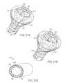
- FIGS. 4A and 4Bshow perspective and end views, respectively, of an imaging hood having at least one layer of a transparent elastomeric membrane over the distal opening of the hood.
- FIGS. 5A and 5Bshow perspective and end views, respectively, of an imaging hood which includes a membrane with an aperture defined therethrough and a plurality of additional openings defined over the membrane surrounding the aperture.
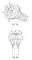
- FIG. 6Ashows a perspective view of one variation where one or more electrodes may be positioned about an opening of the main aperture.
- FIG. 6Bshows a perspective view of another variation where one or more electrodes may be positioned circumferentially about the distal membrane surrounding the main aperture.
- FIG. 6Cshows a perspective view of another variation where one or more electrodes may be positioned circumferentially about a distal portion of the hood.
- FIG. 6Dshows a perspective view of another variation where one or more electrodes may be positioned circumferentially about a mid-portion of the hood.
- FIG. 6Eshows a perspective view of another variation where one or more electrodes may be positioned circumferentially about a proximal portion of the hood.
- FIG. 6Fshows a perspective view of yet another variation where one or more electrodes may be positioned along a length of the hood.
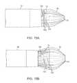
- FIG. 7Ashows a partial cross-sectional side view of another variation where one or more electrodes configured into various shapes, such as squares, rectangles, circles, etc., may be positioned about the distal membrane.
- FIG. 7Bshows a partial cross-sectional side view of another variation where one or more electrodes may be configured into an I-shape to facilitate securement of the electrodes within the distal membrane.
- FIG. 7Cshows a partial cross-sectional side view of yet another variation where one or more electrodes may be configured into a spherical shape projecting at least partially from the distal membrane.
- FIG. 7Dshows a partial cross-sectional side view of yet another variation where the one or more electrodes may be configured into conical shapes having a distal tip projecting from the distal membrane to ensure securement of the electrodes within the distal membrane.
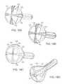
- FIG. 8Ashows a perspective view of another variation where electrodes may be configured into elongate elements which extend radially from the main aperture along the distal membrane.
- FIG. 8Bshows a partial cross-sectional side view of the hood having radially extending electrodes positioned against a tissue surface.
- FIGS. 9A and 9Bshow partial cross-sectional side views of yet another variation where one or more inflatable members each having an electrode formed thereon may be inflated to project from the distal membrane.
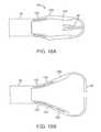
- FIGS. 10A and 10Bshow partial cross-sectional side views of another variation which utilizes a flexible and/or distensible membrane having one or more electrodes formed thereon which may be slid over the hood.
- FIGS. 11A and 11Bshow side and cross-sectional end views, respectively, of a variation which utilizes a flexible and/or distensible material to form a channel extending along the catheter and hood through which an electrode assembly may be advanced.
- FIGS. 12A and 12Bshow side and cross-sectional end views, respectively, of the device of FIGS. 11A and 11B with an electrode assembly advanced through the channel and extended past the hood.
- FIG. 13shows a partial cross-sectional side view of yet another variation where one or more struts supporting the hood may extend towards the distal end of the hood to position corresponding electrodes along the distal membrane.
- FIGS. 14A to 14Cillustrate side, end, and perspective views, respectively, of another variation which utilizes struts of varying length to facilitate the folding or collapsing of the hood membrane into a low profile.
- FIGS. 15A and 15Bshow side views, respectively, of another variation which utilizes a releasable cord to facilitate advancement and delivery of the collapsed hood.
- FIGS. 16A and 16Bshow partial cross-sectional side views of another variation of a hood utilizing struts which are pre-formed to have a bi-stable configuration between low profile and expanded shapes.
- FIGS. 17A to 17Cillustrate one example for forming a hood having integrated conductive members or traces formed within the hood material.
- FIGS. 18A to 18Dillustrate another example for forming a hood also having integrated conductive members formed upon a mandrel which defines one or more channels for the conductive members.
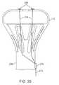
- FIGS. 19A to 19Cillustrate an example of a flattened substrate formed with conductive members extending radially and formed into a conical configuration for placement upon a mandrel for integration into a hood.
- FIGS. 20A to 20Dillustrate various examples of configurations which the conductive members or traces may be formed for placement upon or integration along a hood.
- FIGS. 21A and 21Billustrate perspective views of examples for positioning of a conductive wire assembly upon the hood.
- FIG. 21Cillustrates a detailed cross-sectional perspective view of the conductive wire assembly having a cable core surrounded by one or more conductive wires.
- FIGS. 22A to 22Dillustrate another example of an expandable hood having a separate electrode assembly advanced through the hood interior.
- FIG. 23Ashows a perspective view of another example where a hood assembly having integrated electrodes may utilize connector pins for securement and electrical contact with a receiving assembly defined along the advancement catheter.
- FIG. 23Bshows a perspective view of a catheter distal end having corresponding connector slots for receiving the connector pins of the assembly of FIG. 23A .
- FIG. 24shows a partial cross-sectional side view of a hood assembly having one or more conductive projections which may slide and lock into a receiving channel defined along the catheter distal end.
- FIG. 25shows a partial cross-sectional side view of another hood assembly having integrated electrodes electrically coupled to a processor which may be integrated directly into the hood assembly.
- Reconfiguring a tissue visualization and treatment device from a low profile delivery configuration for intravascular delivery through the vessels of a patient to a deployed and expanded configurationmay subject the distal end effector used for visualization and/or treatment, such as energy delivery, to potentially severe mechanical stresses (e.g., torsion, compression, tension, shearing, etc.).
- a reconfigurable hood which undergoes a shape change from its collapsed configuration to an expanded conical shapemay utilize a distensible, collapsible, and/or reconfigurable substrate which may utilize electrode placement and electrical connection assemblies which are robust and able to withstand such stresses.
- Such electrical connection assembliesmay be shielded or insulated from contacting other structures so as to present a smooth or unobstructive profile for reconfiguring with the hood.
- tissue-imaging and manipulation apparatusupon which one or more electrodes may be positioned and which is able to provide real-time images in vivo of tissue regions within a body lumen such as a heart, which is filled with blood flowing dynamically therethrough and is also able to provide intravascular tools and instruments for performing various procedures upon the imaged tissue regions.
- tissue-imaging and manipulation apparatusmay be utilized for many procedures, e.g., facilitating transseptal access to the left atrium, cannulating the coronary sinus, diagnosis of valve regurgitation/stenosis, valvuloplasty, atrial appendage closure, arrhythmogenic focus ablation, among other procedures.
- tissue imaging and manipulation assembly 10may be delivered intravascularly through the patient's body in a low-profile configuration via a delivery catheter or sheath 14 .
- tissue imaging and manipulation assembly 10may be delivered intravascularly through the patient's body in a low-profile configuration via a delivery catheter or sheath 14 .
- tissue imaging and manipulation assembly 10may be delivered intravascularly through the patient's body in a low-profile configuration via a delivery catheter or sheath 14 .
- tissue imaging and manipulation assembly 10may be delivered intravascularly through the patient's body in a low-profile configuration via a delivery catheter or sheath 14 .
- a transseptal procedure or septostomyTo non-operatively effect such access, one conventional approach involves puncturing the intra-atrial septum from the right atrial chamber to the left atrial chamber in a procedure commonly called a transseptal procedure or septostomy.
- imaging hood 12When the imaging and manipulation assembly 10 is ready to be utilized for imaging tissue, imaging hood 12 may be advanced relative to catheter 14 and deployed from a distal opening of catheter 14 , as shown by the arrow. Upon deployment, imaging hood 12 may be unconstrained to expand or open into a deployed imaging configuration, as shown in FIG. 18 .
- Imaging hood 12may be fabricated from a variety of pliable or conformable biocompatible material including but not limited to, e.g., polymeric, plastic, or woven materials.
- a woven materialis Kevlar® (E. I.
- imaging hood 12may be fabricated from a translucent or opaque material and in a variety of different colors to optimize or attenuate any reflected lighting from surrounding fluids or structures, i.e., anatomical or mechanical structures or instruments. In either case, imaging hood 12 may be fabricated into a uniform structure or a scaffold-supported structure, in which case a scaffold made of a shape memory alloy, such as Nitinol, or a spring steel, or plastic, etc., may be fabricated and covered with the polymeric, plastic, or woven material.
- a shape memory alloysuch as Nitinol, or a spring steel, or plastic, etc.
- imaging hood 12may comprise any of a wide variety of barriers or membrane structures, as may generally be used to localize displacement of blood or the like from a selected volume of a body lumen or heart chamber.
- a volume within an inner surface 13 of imaging hood 12will be significantly less than a volume of the hood 12 between inner surface 13 and outer surface 11 .
- Imaging hood 12may be attached at interface 24 to a deployment catheter 16 which may be translated independently of deployment catheter or sheath 14 . Attachment of interface 24 may be accomplished through any number of conventional methods.
- Deployment catheter 16may define a fluid delivery lumen 18 as well as an imaging lumen 20 within which an optical imaging fiber or assembly may be disposed for imaging tissue.
- imaging hood 12When deployed, imaging hood 12 may expand into any number of shapes, e.g., cylindrical, conical as shown, semi-spherical, etc., provided that an open area or field 26 is defined by imaging hood 12 . The open area 26 is the area within which the tissue region of interest may be imaged.
- Imaging hood 12may also define an atraumatic contact lip or edge 22 for placement or abutment against the tissue region of interest.
- the diameter of imaging hood 12 at its maximum fully deployed diameteris typically greater relative to a diameter of the deployment catheter 16 (although a diameter of contact lip or edge 22 may be made to have a smaller or equal diameter of deployment catheter 16 ).
- the contact edge diametermay range anywhere from 1 to 5 times (or even greater, as practicable) a diameter of deployment catheter 16 .
- FIG. 1Cshows an end view of the imaging hood 12 in its deployed configuration. Also shown are the contact lip or edge 22 and fluid delivery lumen 18 and imaging lumen 20 .
- deployment catheter 16may be manipulated to position deployed imaging hood 12 against or near the underlying tissue region of interest to be imaged, in this example a portion of annulus A of mitral valve MV within the left atrial chamber.
- the translucent fluid 28such as saline, may then be pumped through fluid delivery lumen 18 , intermittently or continuously, until the blood 30 is at least partially, and preferably completely, displaced from within open area 26 by fluid 28 , as shown in FIG. 2B .
- contact edge 22need not directly contact the underlying tissue, it is at least preferably brought into close proximity to the tissue such that the flow of clear fluid 28 from open area 26 may be maintained to inhibit significant backflow of blood 30 back into open area 26 .
- Contact edge 22may also be made of a soft elastomeric material such as certain soft grades of silicone or polyurethane, as typically known, to help contact edge 22 conform to an uneven or rough underlying anatomical tissue surface.
- the fluid 28may be pumped temporarily or sporadically only until a clear view of the tissue is available to be imaged and recorded, at which point the fluid flow 28 may cease and blood 30 may be allowed to seep or flow back into imaging hood 12 . This process may be repeated a number of times at the same tissue region or at multiple tissue regions.
- FIG. 3Ashows a partial cross-sectional view of an example where one or more optical fiber bundles 32 may be positioned within the catheter and within imaging hood 12 to provide direct in-line imaging of the open area within hood 12 .
- FIG. 3Bshows another example where an imaging element 34 (e.g., CCD or CMOS electronic imager) may be placed along an interior surface of imaging hood 12 to provide imaging of the open area such that the imaging element 34 is off-axis relative to a longitudinal axis of the hood 12 , as described in further detail below.
- the off-axis position of element 34may provide for direct visualization and uninhibited access by instruments from the catheter to the underlying tissue during treatment.
- the hood 12may have an open field which is uncovered and clear to provide direct tissue contact between the hood interior and the underlying tissue to effect any number of treatments upon the tissue, as described above. Yet in additional variations, imaging hood 12 may utilize other configurations. An additional variation of the imaging hood 12 is shown in the perspective and end views, respectively, of FIGS. 4A and 4B , where imaging hood 12 includes at least one layer of a transparent elastomeric membrane 40 over the distal opening of hood 12 .
- An aperture 42 having a diameter which is less than a diameter of the outer lip of imaging hood 12may be defined over the center of membrane 40 where a longitudinal axis of the hood intersects the membrane such that the interior of hood 12 remains open and in fluid communication with the environment external to hood 12 .
- aperture 42may be sized, e.g., between 1 to 2 mm or more in diameter and membrane 40 can be made from any number of transparent elastomers such as silicone, polyurethane, latex, etc. such that contacted tissue may also be visualized through membrane 40 as well as through aperture 42 .
- Aperture 42may function generally as a restricting passageway to reduce the rate of fluid out-flow from the hood 12 when the interior of the hood 12 is infused with the clear fluid through which underlying tissue regions may be visualized. Aside from restricting out-flow of clear fluid from within hood 12 , aperture 42 may also restrict external surrounding fluids from entering hood 12 too rapidly. The reduction in the rate of fluid out-flow from the hood and blood in-flow into the hood may improve visualization conditions as hood 12 may be more readily filled with transparent fluid rather than being filled by opaque blood which may obstruct direct visualization by the visualization instruments.
- aperture 42may be aligned with catheter 16 such that any instruments (e.g., piercing instruments, guidewires, tissue engagers, etc.) that are advanced into the hood interior may directly access the underlying tissue uninhibited or unrestricted for treatment through aperture 42 .
- instruments passed through catheter 16may still access the underlying tissue by simply piercing through membrane 40 .
- FIGS. 5A and 5Bshow perspective and end views, respectively, of imaging hood 12 which includes membrane 40 with aperture 42 defined therethrough, as described above.
- This variationincludes a plurality of additional openings 44 defined over membrane 40 surrounding aperture 42 .
- Additional openings 44may be uniformly sized, e.g., each less than 1 mm in diameter, to allow for the out-flow of the translucent fluid therethrough when in contact against the tissue surface.
- openings 44are illustrated as uniform in size, the openings may be varied in size and their placement may also be non-uniform or random over membrane 40 rather than uniformly positioned about aperture 42 in FIG. 5B .
- there are eight openings 44 shown in the figuresalthough fewer than eight or more than eight openings 44 may also be utilized over membrane 40 .
- various proceduresmay be accomplished.
- a procedureis crossing a tissue region such as in a transseptal procedure where a septal wall is pierced and traversed, e.g., crossing from a right atrial chamber to a left atrial chamber in a heart of a subject.
- the visualization and treatment devices described hereinmay be utilized for visualizing the tissue region to be pierced as well as monitoring the piercing and access through the tissue. Details of transseptal visualization catheters and methods for transseptal access which may be utilized with the apparatus and methods described herein are described in U.S.
- Electrodesmay be used to deliver electrical energy such as radio-frequency energy to tissue in direct contact with or in proximity to the electrodes to form lesions upon the tissue surface as well as underlying tissue regions. Additionally, the electrodes or electrode pairs may be positioned about the hood in a uniform or non-uniform manner depending upon the desired configuration. Moreover, these electrodes may also be used to deliver energy into and/or through the purging fluid which may contact the electrodes for conducting the energy through the fluid and into the underlying tissue region being treated. Alternatively, one or more of these electrodes may also be used to detect and/or measure any electrophysiological activity of the contacted tissue prior to, during, or after tissue treatment.
- hoods and tissue treatment systemsmay be utilized herewith.
- Ser. No. 11/259,498 filed Oct. 25, 2005U.S. Pat. Pub. 2006/0184048 A1
- Ser. No. 11/775,837 filed Jul. 10, 2007U.S. Pat. Pub. 2008/0009747 A1
- Ser. No. 12/118,439 filed May 9, 2008U.S. Pat. Pub. 2009/0030412 A1
- Ser. No. 12/201,811 filed Aug. 29, 2008U.S. Pat. Pub. 2009/0062790 A1
- Ser. No. 12/209,057 filed Sep. 11, 2008U.S. Pat. Pub. 20090076498 A1
- Each of these applicationsis incorporated herein by reference in its entirety.
- FIG. 6Aillustrates one example of a hood shown in a perspective view where one or more electrodes or electrode pairs 50 may be positioned (uniformly or non-uniformly) about the main aperture 42 .
- the electrodes 50may thus contact the underlying tissue when placed into apposition against the tissue region to be visualized and/or treated or they may conduct the energy through the purging fluid into the tissue as the fluid passes over the electrodes from the hood interior.
- Each of the electrodes 50may be formed or adhered directly to the hood surface or they may also be integrated directly into the hood material (as described in further detail below).
- each of the electrodes 50may be connected via an electrical connection (e.g., metal wires, filament strand material, conductive polymers, silver emulsion, carbon black track, carbon nanotubes, graphite fiber, metal film deposition or conductive fluids, etc.) to a proximal end of the hood 12 and through the catheter to power supply and/or signal processor.
- an electrical connectione.g., metal wires, filament strand material, conductive polymers, silver emulsion, carbon black track, carbon nanotubes, graphite fiber, metal film deposition or conductive fluids, etc.
- FIG. 6Bshows a perspective view of another example where the one or more electrodes may be positioned upon the distal membrane 40 circumferentially about the main aperture 42 .
- FIG. 6Cshows the one or more electrodes 50 positioned circumferentially upon a distal curved portion 52 of hood 12 .
- FIG. 6Dshows a perspective view of electrodes 50 positioned circumferentially about hood 12 proximally of the distal curved portion 52 while FIG. 6E likewise shows another variation where electrodes 50 are positioned circumferentially about hood 12 distal to the hood connecting member 54 .
- FIG. 6Fshows yet another variation where one or more electrodes 50 may be positioned along the hood 12 longitudinally between the main aperture 42 and connecting member 54 .
- FIG. 7Ashows a partial cross-sectional side view of one example where electrodes 64 may be secured or adhered directly to the outer surface 60 of hood 12 as pads or contacts, e.g., shown illustratively along the distal membrane 40 although the electrodes 64 may be positioned elsewhere along hood 12 .
- the one or more electrodes 64may be formed into various shapes, e.g., square, rectangular, circular, triangular, etc.
- FIG. 7Bshows another example where electrodes 66 may be I-shaped such that the electrodes extend between the outer surface 60 of the hood membrane and the inner surface 62 .
- the upper portion of the I-shaped electrode 66may extend radially out along the outer surface 60 while the lower portion of the electrode 66 may similarly extend radially out along the inner surface 62 such that the intermediate portion of the electrode 66 extends therebetween and is securely held in place between the outer 60 and inner 62 surfaces of hood 12 .
- FIG. 7Cshows a partial cross-sectional side view of another variation where spherically-shaped electrodes 68 may be integrated along the hood 12 such that a portion of the electrodes 68 is embedded within the hood 12 while a remainder projects distally from the hood outer surface 60 .
- FIG. 7Dshows conically-shaped electrodes 70 where the base portion of each electrode 70 may be embedded within the hood material while the apex of the electrode 70 extends past the outer surface 60 of hood 12 and projects distally for contact against or into proximity with the tissue to be treated.
- the electrodesare positioned upon or within the hood 12 such that they are securely attached thereto.
- the one or more electrodesmay remain securely adhered or attached to the hood 12 .
- FIG. 8Aillustrates one or more electrodes 80 which are shaped as elongate elements which extend radially from the main aperture 42 over the distal membrane 40 .
- four electrodes 80are illustrated, there may be fewer or more than four utilized.
- Each of the electrodes 80may extend over distal membrane 40 and project distally from the surface of membrane 40 .
- the electrodes 80may form gaps 84 between the distal membrane 40 and tissue surface.
- the purging fluid 82is introduced into the hood interior and out through aperture 42 , the fluid 82 may not only clear any blood from the gaps 84 to enhance visualization, but it may also conduct energy from the electrodes 80 for tissue treatment as well.
- FIGS. 9A and 9Bshow cross-sectional side views of a hood 12 having one or more electrodes 90 positioned upon expandable chambers defined along the hood outer surface 60 .
- the expandable chambers, shown along the distal membrane,may each have an electrode 90 integrated thereon; moreover, each of the chambers may be expanded from a flaccid or unexpanded shape to an inflated configuration where the one or more chambers may be inflated via an inflation fluid or gas 94 passed through one or more inflation channels 92 defined between the outer 60 and inner 62 surfaces of hood 12 .
- an inflation fluid or gas 94passed through one or more inflation channels 92 defined between the outer 60 and inner 62 surfaces of hood 12 .
- the electrodes 90may be projected distally from the hood 12 such that the electrodes 90 are placed into direct contact against the underlying tissue while maintaining the hood a distance from the tissue surface.
- the one or more chambersmay be fabricated from the same or similar material as the remainder of the hood 12 .
- FIGS. 10A and 10Billustrate another variation where a covering assembly 100 comprised of a distensible, flexible, and/or scaffold-like material may be placed directly over the hood assembly.
- the covering assembly 100may be comprised of a mesh-like or elastic material or the same or similar material as the hood 12 and have one or more electrodes 108 positioned upon a contact portion 106 of the covering which may slide upon the distal membrane 40 of hood 12 .
- the distal portion 102 of covering 100may also define an opening which is coincident with the main aperture of hood 12 to permit the exiting flow of the purging fluid.
- portions of the covering 100may be made to be more or less flexible than the remainder of the assembly.
- a proximal portion 104 of the covering 100may be fabricated to be more flexible than the distal portion 102 to enable covering 100 to more closely conform to the contours of hood 12 and the catheter.
- FIGS. 11A and 11BAnother variation is shown in the side and cross-sectional end views, respectively, of FIGS. 11A and 11B .
- the electrode assemblymay be advanced along the catheter and expanded hood independently, the electrode assembly does not experience the mechanical stresses of hood delivery and deployment.
- An expandable delivery channel 110may be formed along the length of the catheter 16 and extend at least partially along the hood 12 such that a lumen 112 is defined through the length of the channel 110 .
- An electrode assemblyfor example, a reconfigurable ring electrode 116 advanced upon an electrode shaft 114 , may be advanced through the length of the expandable channel 110 in a low profile and deployed distal to the hood 12 once the hood 12 has been desirably expanded, as illustrated in the side and cross-sectional views of FIGS. 12A and 12B .
- FIG. 13illustrates a hood assembly 120 having one or more extended struts 124 which extend from the catheter 16 to the distal end of the hood 12 .
- the one or more extended struts 124may extend past the remaining struts 122 such that the distal ends of the extended struts 124 are flush with or project past the distal membrane 40 to contact the underlying tissue.
- the extended struts 124may thus have electrodes positioned upon their distal ends for placement against the tissue while maintaining an electrical connection 126 through the struts 124 . Utilizing the struts 124 as electrodes may take advantage of the robustness and strength provided by the struts 124 which are better suited to handle the mechanical stresses imparted upon the electrodes during hood delivery and deployment.
- FIGS. 14A to 14Cshow another example in the side, end, and perspective views of another variation where the hood assembly may be configured to collapse or fold in a predetermined and consistent manner such that electrodes may be placed at locations upon the hood 12 which have a lower stress potential, e.g., along a portion of the hood 12 which is not folded for delivery or collapse.
- One mechanism for achieving thisis to utilize struts of different lengths. For instance, struts 130 which extend along the hood 12 may be alternated with shortened struts 132 which are relatively shorter in length.
- shortened struts 132which alternate with the longer struts 130 ; however, shortened struts 132 may be arranged in any number of other configurations if so desired. Because of the additional space created by the shortened struts 132 when hood 12 is collapsed, the collapsed portions 134 of hood 12 may collapse or fold consistently between the struts 130 along where the shortened struts 132 fold. Accordingly, with the hood 12 collapsing in a consistent folding pattern, electrodes or wires may be positioned along portions of the hood 12 which are not folded aside from the collapsed portions 134 .
- FIGS. 15A and 15Billustrate side views of another variation where a collapsed hood 12 may be initially folded and maintained in its collapsed configuration by a restraining member 142 prior to positioning the collapsed hood within the sheath 14 .
- the maintenance of the hood 12 in its collapsed configurationallows for the initial retraction within the sheath 14 and subsequent deployment from the sheath 14 with a reduced stress load on the hood 12 as friction and sliding contact between the hood 12 and sheath 14 is reduced.
- Restraining member 142may comprise a wire or ribbon which may be wrapped about the struts 140 of hood 12 to restrain the hood 12 from expansion.
- hood 12may be advanced from sheath 14 and a tensioning member 144 or release may be pulled or actuated to release the restraining member 142 from around the hood 12 , as shown in FIG. 15B , e.g., by releasing a knot or simply breaking the restraining member 142 .
- Restraining member 142may be removed by pulling it proximally through sheath 14 .
- FIGS. 16A and 16Billustrate a hood having a bi-stable strut assembly 150 , i.e., struts which are preformed to have at least two mechanically stable configurations.
- a first configurationis shown in FIG. 16A where the struts may comprise a proximal portion 152 , an intermediate hinged portion 154 , and a distal portion 156 which collapses into a low profile when hood 12 is positioned within the sheath for delivery.
- a mechanismsuch as a push/pull wire
- hood 12may transition from its stable low-profile configuration into a second configuration which is also mechanically stable, as shown in FIG. 16B .
- electrical tracesmay be laid upon the hood 12 for maintaining electrical communication with the various electrodes.
- Such tracesmay be made of conductive materials through any number of methods, e.g., chemical vapor deposition, laser etching, micropen writing, adhesives, etc.
- the tracesare desirably insulated along their lengths through any number of mechanisms.
- use of traces placed within or along the hood 12allows for added flexibility in connecting the electrodes along the hood to a power source and/or processor.
- FIGS. 17A to 17Cshow one variation for laying down traces integrated within a hood 12 .
- a robust electrical connection to the one or more electrodesmay be maintained as the hood reconfigures between its low profile and deployed shapes.
- a mandrel 160 shaped in the form of the hood in its deployed configurationmay be coated first with a first layer 162 such as an elastomeric material (e.g., silicone, chronoflex, polyurethane, etc.) which may be sufficiently dried or cured.
- a first layer 162such as an elastomeric material (e.g., silicone, chronoflex, polyurethane, etc.) which may be sufficiently dried or cured.
- One or more conductive traces 164may be then laid upon the first layer 162 utilizing any of the methods mentioned and in any number of desired patterns extending along or over the first layer 162 and proximally along the mandrel 160 for electrical connection, as shown in FIG. 17A .
- a second layer 166 of materialwhich may be the same or a similar material as the first layer 162 may then be laid atop both the first layer 162 and the conductive traces 164 , as shown in FIG. 17B , to sandwich and electrical insulate the conductive traces 164 from the environment as well as from one another.
- the mandrel 160may then be removed either physically or chemically from the conductive hood assembly.
- mandrel 160may provide the desired structural support for building the layers of material and conductive traces 164 and when the mandrel 160 is to be removed, the entire assembly may be soaked in a chemical such as acetone to dissolve the mandrel 160 yet leave the first and second layers 162 , 166 and sandwiched conductive traces 164 intact. With the mandrel 160 removed, the remaining hood structure may have one or more apertures, such as a main aperture 42 , formed or cut into the distal membrane portion of the hood, as shown in FIG. 17C . Moreover, one or more electrodes may also be positioned anywhere along the length of the conductive traces 164 by exposing a corresponding portion of the underlying sandwiched trace.
- a chemicalsuch as acetone
- FIGS. 18A to 18DAnother example of integrating conductive traces within the hood is illustrated in the perspective views of FIGS. 18A to 18D .
- a mandrel 170similar to the previous example may be utilized to form the hood upon.
- mandrel 170may define one or more grooves or channels 172 along the mandrel surface to facilitate the formation of conductive traces within.
- FIG. 18Ashows mandrel 170 having its grooves or channels 172 coated or covered by a first layer 174 , as previously described.
- the one or more conductive traces 176may be laid atop the first layer 174 within the grooves or channels 172 once the first layer 174 has sufficiently cured or dried, as shown in FIG. 18B .
- a second layer 178 of materialmay then be laid atop the first layer 174 as well as the conductive traces 176 , as shown in FIG. 18C .
- the mandrel 170may be removed physically or chemically and the one or more apertures, such as main aperture 42 may be formed within the distal membrane portion, as shown in FIG. 18D .
- the second layer 178may form a smooth exterior hood surface despite the presence of the underlying sandwiched traces due to the flush formation of the traces within the depressed grooves or channels 172 . By avoiding the formation of bumps or an irregular profile along the hood surface, the passage of the hood within or through an outer sheath may be facilitated.
- yet another variationmay utilize the assembly shown in which rods or other structures made from a dissolvable material, such as acrylic, may be laid within or along the length of the grooves or channels 172 and sandwiched between the first layer 174 and second layer 178 .
- the resulting assemblyas shown in FIG. 18D , may then be soaked within a chemical such as acetone to dissolve not only mandrel 170 but also the encased rods or structures such that a cavity or lumen is formed through the hood where the grooves or channels 172 were initially defined.
- a conductive fluidmay then introduced directly through the formed cavity or lumen to provide a conductive pathway for connection to the one or more electrodes.
- FIG. 19Ashows example of a flexible electrode assembly 180 formed of one or more conductive traces 188 which are encased or integrated within a polymeric substrate 182 , which may be formed in a process similar to that described above.
- the assembly 180 variation shownillustrates a substrate which may be formed in the shape of an arc having a first inner radius 184 and a second outer radius 186 .
- the conductive traces 188are illustrated in a radial pattern extending between the first radius 184 and the second radius 186 , any number of patterns may be utilized depending upon the desired positioning of the one or more electrodes along the hood.
- the terminal edges 190 of the substratemay be joined, as shown in the perspective view of FIG. 19B , to form a conical structure which may then be laid atop a mandrel 170 for subsequent coating by additional layers of elastomeric material, as shown in the perspective view of FIG. 19C and as previously described.
- This particular variationmay facilitate the manufacturability of the hood having integrated conductive traces within. As previously mentioned, this as well as other examples for integrating conductive traces within or along the hood assembly may be utilized within any of the electrode positioning embodiments described herein.
- the tracesare desirably robust enough to withstand the high mechanical stresses which are imparted to the traces as the hood undergoes introduction and removal from the sheath as well as the reconfiguration between its low profile and deployed profile.
- the tracesmay be laid in any number of patterns which may alleviate the stresses imparted to the traces. Traces may accordingly be laid in, e.g., straight patterns 200 (as shown in FIG. 20A ), or curved patterns 202 (as shown in FIG. 20B ). Alternatively, the traces may also be laid in, e.g., saw-tooth patterns 204 (as shown in FIG.
- looped and/or helical patterns 206may allow for expansion and/or contraction of the trace without breaking or losing electrical continuity through the trace.
- FIG. 21Aillustrates a perspective view of a deployed hood 12 with a conductive cable assembly 210 .
- Cable assembly 210may be positioned to extend along the length of hood 12 to form a looped portion 212 at least partially encircling the main aperture 42 .
- Looped portion 212may comprise one or more exposed electrode segments 214 for contact against the underlying tissue.
- FIG. 21Bshows a perspective view of another variation where cable assembly 210 may be wrapped about hood 12 in a helical pattern such that looped portion 212 terminates about main aperture 42 to alleviate mechanical stresses imparted upon assembly 210 during hood reconfiguration.
- the cablemay generally comprise a core wire 220 having a first diameter which provides mechanical strength to the assembly 210 , as shown in the detailed cross-sectional perspective view of FIG. 21C .
- Core wire 220may be surrounded by individual lengths of adjacent conductive wires 218 each of which have a second diameter which is smaller than the first diameter of the core wire 220 .
- the entire assemblymay be encased by an insulative outer covering 216 which may be exposed at regions where electrode segments 214 are positioned.
- FIGS. 22A to 22DAnother variation for forming a robust system for maintaining electrical communication is shown in the side views of FIGS. 22A to 22D .
- the one or more electrodesmay be disposed upon the hood but the electrical connection to the electrodes may be deployed separately from the hood deployment.
- hood 12may be advanced from sheath 14 from its low profile and deployed into its expanded profile.
- An expandable electrode assembly 230 separate from the hood 12may then be advanced through catheter 16 and into hood 12 .
- Electrode assembly 230may generally comprise a conductive support member 232 having one or more conductive branching members 234 which are reconfigurable from a low profile configuration, where each of the branching members 234 are compressed, to an expanded configuration, where several branching members 234 may reconfigure into a deployed configuration.
- Each of the deployed branching members 234may extend at an angle such that the members 234 come into electrical contact with corresponding electrode pads 236 positioned along the hood 12 , as shown in the side views of FIGS. 22C and 22D .
- FIG. 23Aone variation of a hood assembly having a connector base 240 is shown with one or more electrode connector pins 242 projecting from the connector base 240 .
- the one or more connector pins 242may be electrically coupled to one or more corresponding electrodes positioned within or along the hood 12
- the hood assemblymay be connected, electrically as well as mechanically, to the catheter 16 by the insertion of connector pins 242 into one or more electrode receiving slots 244 , as shown in the perspective view of FIG. 23B , which may be in electrical communication with a power supply and/or processor through the length of the catheter 16 .
- the insertion and coupling of the connector pins 242 with the receiving slots 244helps to ensure a secure electrical and mechanical connection as the hood 12 is delivered and deployed.
- FIG. 24shows a partial cross-sectional side view of a hood assembly having a connector base 250 with one or more conductive studs or projections 252 extending from the base 250 .
- Each conductive stud or projection 252may be electrically coupled via conductive wires 254 to one or more corresponding electrodes 256 position within or along hood 12 . Because the studs or projections 252 extend from a surface of the base 250 , a receiving channel 258 may be defined longitudinally along the distal end of the catheter 16 .
- the receiving channel 258may further define a locking channel 260 which extends from receiving channel 258 at an angle, e.g., perpendicularly, such that as the base 250 of the hood assembly is coupled to catheter 16 the base 250 is forced to be twisted as the one or more projections 252 are guided along receiving channel 258 and then along the angled locking channel 260 .
- This direction of movementas indicated by locking direction 266 , may force the one or more projections 252 into secure contact against one or more corresponding conductive contacts 262 which may be in electrical communication through catheter 16 via corresponding conductive wires 264 .
- the twisting of the hood assembly relative to the catheter 16further helps to ensure rigidity of the coupling as well as electrical isolation between electrodes.
- the electrical connection systems to and from the electrodesmay be terminated locally along the hood assembly itself.
- the electrodesmay be electrically coupled to a local signal processor 270 attached, e.g., to the base 250 of the hood assembly.
- the signal processor 270may generally comprise at least a single microprocessor for processing and outputting any received and processed signal through a single wire 272 passed through the catheter.
Landscapes
- Health & Medical Sciences (AREA)
- Life Sciences & Earth Sciences (AREA)
- Surgery (AREA)
- General Health & Medical Sciences (AREA)
- Animal Behavior & Ethology (AREA)
- Veterinary Medicine (AREA)
- Public Health (AREA)
- Radiology & Medical Imaging (AREA)
- Nuclear Medicine, Radiotherapy & Molecular Imaging (AREA)
- Engineering & Computer Science (AREA)
- Biomedical Technology (AREA)
- Heart & Thoracic Surgery (AREA)
- Biophysics (AREA)
- Molecular Biology (AREA)
- Medical Informatics (AREA)
- Physics & Mathematics (AREA)
- Pathology (AREA)
- Optics & Photonics (AREA)
- Cardiology (AREA)
- Surgical Instruments (AREA)
Abstract
Description
Claims (5)
Priority Applications (5)
| Application Number | Priority Date | Filing Date | Title |
|---|---|---|---|
| US12/575,674US8333012B2 (en) | 2008-10-10 | 2009-10-08 | Method of forming electrode placement and connection systems |
| US12/778,907US8894643B2 (en) | 2008-10-10 | 2010-05-12 | Integral electrode placement and connection systems |
| US14/538,594US10111705B2 (en) | 2008-10-10 | 2014-11-11 | Integral electrode placement and connection systems |
| US16/159,301US11950838B2 (en) | 2008-10-10 | 2018-10-12 | Integral electrode placement and connection systems |
| US18/596,469US20240206967A1 (en) | 2008-10-10 | 2024-03-05 | Integral electrode placement and connection systems |
Applications Claiming Priority (2)
| Application Number | Priority Date | Filing Date | Title |
|---|---|---|---|
| US10465008P | 2008-10-10 | 2008-10-10 | |
| US12/575,674US8333012B2 (en) | 2008-10-10 | 2009-10-08 | Method of forming electrode placement and connection systems |
Related Child Applications (1)
| Application Number | Title | Priority Date | Filing Date |
|---|---|---|---|
| US12/778,907Continuation-In-PartUS8894643B2 (en) | 2008-10-10 | 2010-05-12 | Integral electrode placement and connection systems |
Publications (2)
| Publication Number | Publication Date |
|---|---|
| US20100094081A1 US20100094081A1 (en) | 2010-04-15 |
| US8333012B2true US8333012B2 (en) | 2012-12-18 |
Family
ID=42099484
Family Applications (1)
| Application Number | Title | Priority Date | Filing Date |
|---|---|---|---|
| US12/575,674Active2031-04-28US8333012B2 (en) | 2008-10-10 | 2009-10-08 | Method of forming electrode placement and connection systems |
Country Status (1)
| Country | Link |
|---|---|
| US (1) | US8333012B2 (en) |
Cited By (33)
| Publication number | Priority date | Publication date | Assignee | Title |
|---|---|---|---|---|
| US20090093810A1 (en)* | 2007-10-09 | 2009-04-09 | Raj Subramaniam | Electrophysiology Electrodes and Apparatus Including the Same |
| US8694071B2 (en) | 2010-02-12 | 2014-04-08 | Intuitive Surgical Operations, Inc. | Image stabilization techniques and methods |
| US8934962B2 (en) | 2005-02-02 | 2015-01-13 | Intuitive Surgical Operations, Inc. | Electrophysiology mapping and visualization system |
| US9014789B2 (en) | 2011-09-22 | 2015-04-21 | The George Washington University | Systems and methods for visualizing ablated tissue |
| US9055906B2 (en) | 2006-06-14 | 2015-06-16 | Intuitive Surgical Operations, Inc. | In-vivo visualization systems |
| US9084611B2 (en) | 2011-09-22 | 2015-07-21 | The George Washington University | Systems and methods for visualizing ablated tissue |
| US9192287B2 (en) | 2005-10-25 | 2015-11-24 | Intuitive Surgical Operations, Inc. | Tissue visualization device and method variations |
| US9226648B2 (en) | 2006-12-21 | 2016-01-05 | Intuitive Surgical Operations, Inc. | Off-axis visualization systems |
| US9333031B2 (en) | 2013-04-08 | 2016-05-10 | Apama Medical, Inc. | Visualization inside an expandable medical device |
| US9332893B2 (en) | 2005-02-02 | 2016-05-10 | Intuitive Surgical Operations, Inc. | Delivery of biological compounds to ischemic and/or infarcted tissue |
| US9510732B2 (en) | 2005-10-25 | 2016-12-06 | Intuitive Surgical Operations, Inc. | Methods and apparatus for efficient purging |
| US9526401B2 (en) | 2005-02-02 | 2016-12-27 | Intuitive Surgical Operations, Inc. | Flow reduction hood systems |
| US9610006B2 (en) | 2008-11-11 | 2017-04-04 | Shifamed Holdings, Llc | Minimally invasive visualization systems |
| US9655677B2 (en) | 2010-05-12 | 2017-05-23 | Shifamed Holdings, Llc | Ablation catheters including a balloon and electrodes |
| US9795442B2 (en) | 2008-11-11 | 2017-10-24 | Shifamed Holdings, Llc | Ablation catheters |
| US10004388B2 (en) | 2006-09-01 | 2018-06-26 | Intuitive Surgical Operations, Inc. | Coronary sinus cannulation |
| US10064540B2 (en) | 2005-02-02 | 2018-09-04 | Intuitive Surgical Operations, Inc. | Visualization apparatus for transseptal access |
| US10070772B2 (en) | 2006-09-01 | 2018-09-11 | Intuitive Surgical Operations, Inc. | Precision control systems for tissue visualization and manipulation assemblies |
| US10092172B2 (en) | 2007-05-08 | 2018-10-09 | Intuitive Surgical Operations, Inc. | Complex shape steerable tissue visualization and manipulation catheter |
| US10098694B2 (en) | 2013-04-08 | 2018-10-16 | Apama Medical, Inc. | Tissue ablation and monitoring thereof |
| US10111705B2 (en) | 2008-10-10 | 2018-10-30 | Intuitive Surgical Operations, Inc. | Integral electrode placement and connection systems |
| US10143517B2 (en) | 2014-11-03 | 2018-12-04 | LuxCath, LLC | Systems and methods for assessment of contact quality |
| US10349824B2 (en) | 2013-04-08 | 2019-07-16 | Apama Medical, Inc. | Tissue mapping and visualization systems |
| US10722301B2 (en) | 2014-11-03 | 2020-07-28 | The George Washington University | Systems and methods for lesion assessment |
| US10736693B2 (en) | 2015-11-16 | 2020-08-11 | Apama Medical, Inc. | Energy delivery devices |
| US10779904B2 (en) | 2015-07-19 | 2020-09-22 | 460Medical, Inc. | Systems and methods for lesion formation and assessment |
| US10813687B2 (en) | 2007-10-09 | 2020-10-27 | Boston Scientific Scimed Inc | Cooled ablation catheter devices and methods of use |
| US11096584B2 (en) | 2013-11-14 | 2021-08-24 | The George Washington University | Systems and methods for determining lesion depth using fluorescence imaging |
| US11406250B2 (en) | 2005-02-02 | 2022-08-09 | Intuitive Surgical Operations, Inc. | Methods and apparatus for treatment of atrial fibrillation |
| US11457817B2 (en) | 2013-11-20 | 2022-10-04 | The George Washington University | Systems and methods for hyperspectral analysis of cardiac tissue |
| US11478152B2 (en) | 2005-02-02 | 2022-10-25 | Intuitive Surgical Operations, Inc. | Electrophysiology mapping and visualization system |
| US12076081B2 (en) | 2020-01-08 | 2024-09-03 | 460Medical, Inc. | Systems and methods for optical interrogation of ablation lesions |
| US12408824B2 (en) | 2005-02-02 | 2025-09-09 | Intuitive Surgical Operations, Inc. | Tissue visualization and manipulation system |
Families Citing this family (21)
| Publication number | Priority date | Publication date | Assignee | Title |
|---|---|---|---|---|
| US8050746B2 (en) | 2005-02-02 | 2011-11-01 | Voyage Medical, Inc. | Tissue visualization device and method variations |
| US20080009747A1 (en)* | 2005-02-02 | 2008-01-10 | Voyage Medical, Inc. | Transmural subsurface interrogation and ablation |
| US10335131B2 (en)* | 2006-10-23 | 2019-07-02 | Intuitive Surgical Operations, Inc. | Methods for preventing tissue migration |
| US20080183036A1 (en) | 2006-12-18 | 2008-07-31 | Voyage Medical, Inc. | Systems and methods for unobstructed visualization and ablation |
| EP2148608A4 (en) | 2007-04-27 | 2010-04-28 | Voyage Medical Inc | Complex shape steerable tissue visualization and manipulation catheter |
| WO2008141238A1 (en) | 2007-05-11 | 2008-11-20 | Voyage Medical, Inc. | Visual electrode ablation systems |
| US8235985B2 (en) | 2007-08-31 | 2012-08-07 | Voyage Medical, Inc. | Visualization and ablation system variations |
| US8858609B2 (en) | 2008-02-07 | 2014-10-14 | Intuitive Surgical Operations, Inc. | Stent delivery under direct visualization |
| US9101735B2 (en) | 2008-07-07 | 2015-08-11 | Intuitive Surgical Operations, Inc. | Catheter control systems |
| US8333012B2 (en) | 2008-10-10 | 2012-12-18 | Voyage Medical, Inc. | Method of forming electrode placement and connection systems |
| US9468364B2 (en) | 2008-11-14 | 2016-10-18 | Intuitive Surgical Operations, Inc. | Intravascular catheter with hood and image processing systems |
| US9211140B2 (en)* | 2010-11-24 | 2015-12-15 | Kyphon Sarl | Dynamically expandable cannulae and systems and methods for performing percutaneous surgical procedures employing same |
| US10391277B2 (en) | 2011-02-18 | 2019-08-27 | Voxel Rad, Ltd. | Systems and methods for 3D stereoscopic angiovision, angionavigation and angiotherapeutics |
| CN103006199B (en)* | 2011-09-26 | 2016-09-28 | 三星电子株式会社 | For measuring equipment and the method for bio signal |
| KR101941171B1 (en)* | 2011-09-26 | 2019-01-23 | 삼성전자주식회사 | Apparatus and method for measuring biological signal |
| JP7142086B2 (en)* | 2017-10-25 | 2022-09-26 | ボストン サイエンティフィック サイムド,インコーポレイテッド | Direct visualization catheters and systems |
| CN108888863A (en)* | 2018-06-29 | 2018-11-27 | 成都三乙医疗科技有限公司 | A kind of sucked type electrode slice |
| US11357958B2 (en)* | 2018-10-25 | 2022-06-14 | Medtronic Vascular, Inc. | Devices and techniques for cardiovascular intervention |
| US10806339B2 (en) | 2018-12-12 | 2020-10-20 | Voxel Rad, Ltd. | Systems and methods for treating cancer using brachytherapy |
| US11280688B2 (en)* | 2019-10-18 | 2022-03-22 | Korea Advanced Institute Of Science And Technology | Core-shell structured fiber type strain sensor and method of manufacturing the same |
| GB202205559D0 (en)* | 2022-04-14 | 2022-06-01 | Imperial College Innovations Ltd | Multi-electrode catheter |
Citations (428)
| Publication number | Priority date | Publication date | Assignee | Title |
|---|---|---|---|---|
| US623022A (en) | 1899-04-11 | johnson | ||
| US2305462A (en) | 1940-06-20 | 1942-12-15 | Wolf Richard | Cystoscopic instrument |
| US2453862A (en) | 1947-06-02 | 1948-11-16 | Salisbury Peter Frederic | Gastroscope |
| US3559651A (en) | 1968-10-14 | 1971-02-02 | David H Moss | Body-worn all disposable urinal |
| US3874388A (en) | 1973-02-12 | 1975-04-01 | Ochsner Med Found Alton | Shunt defect closure system |
| US4175545A (en) | 1977-03-10 | 1979-11-27 | Zafmedico Corp. | Method and apparatus for fiber-optic cardiovascular endoscopy |
| US4326529A (en) | 1978-05-26 | 1982-04-27 | The United States Of America As Represented By The United States Department Of Energy | Corneal-shaping electrode |
| US4445892A (en) | 1982-05-06 | 1984-05-01 | Laserscope, Inc. | Dual balloon catheter device |
| JPS5993413A (en) | 1982-11-18 | 1984-05-29 | Olympus Optical Co Ltd | Endoscope |
| US4470407A (en) | 1982-03-11 | 1984-09-11 | Laserscope, Inc. | Endoscopic device |
| US4517976A (en) | 1981-10-20 | 1985-05-21 | Fuji Photo Film Co., Ltd. | High frequency scalpel and endoscope system and method of operating same |
| US4569335A (en) | 1983-04-12 | 1986-02-11 | Sumitomo Electric Industries, Ltd. | Fiberscope |
| US4576146A (en) | 1983-03-22 | 1986-03-18 | Sumitomo Electric Industries, Ltd. | Fiberscope |
| US4615333A (en) | 1984-02-03 | 1986-10-07 | Olympus Optical Co., Ltd. | Rigid endoscope of oblique window type |
| US4619247A (en) | 1983-03-31 | 1986-10-28 | Sumitomo Electric Industries, Ltd. | Catheter |
| US4676258A (en) | 1983-01-24 | 1987-06-30 | Kureha Kagaku Kogyo Kabushiki Kaisha | Device for hyperthermia |
| US4681093A (en) | 1982-12-13 | 1987-07-21 | Sumitomo Electric Industries, Ltd. | Endoscope |
| US4709698A (en) | 1986-05-14 | 1987-12-01 | Thomas J. Fogarty | Heatable dilation catheter |
| US4710192A (en) | 1985-12-30 | 1987-12-01 | Liotta Domingo S | Diaphragm and method for occlusion of the descending thoracic aorta |
| US4727418A (en) | 1985-07-02 | 1988-02-23 | Olympus Optical Co., Ltd. | Image processing apparatus |
| EP0283661A2 (en) | 1987-01-28 | 1988-09-28 | Robert A. Mackin | Angioscope having a balloon with a recess |
| EP0301288A1 (en) | 1987-07-31 | 1989-02-01 | Confida S.P.A. | Flexible endoscope |
| US4848323A (en) | 1987-02-11 | 1989-07-18 | Daniel Den Hoed Stichting | Apparatus for, and method of, examining and/or illuminating a body cavity |
| US4911148A (en) | 1989-03-14 | 1990-03-27 | Intramed Laboratories, Inc. | Deflectable-end endoscope with detachable flexible shaft assembly |
| US4914521A (en) | 1989-02-03 | 1990-04-03 | Adair Edwin Lloyd | Sterilizable video camera cover |
| US4943290A (en) | 1987-06-23 | 1990-07-24 | Concept Inc. | Electrolyte purging electrode tip |
| US4950285A (en) | 1989-11-27 | 1990-08-21 | Wilk Peter J | Suture device |
| US4957484A (en) | 1988-07-26 | 1990-09-18 | Automedix Sciences, Inc. | Lymph access catheters and methods of administration |
| US4961738A (en) | 1987-01-28 | 1990-10-09 | Mackin Robert A | Angioplasty catheter with illumination and visualization within angioplasty balloon |
| US4976710A (en)* | 1987-01-28 | 1990-12-11 | Mackin Robert A | Working well balloon method |
| US4991578A (en) | 1989-04-04 | 1991-02-12 | Siemens-Pacesetter, Inc. | Method and system for implanting self-anchoring epicardial defibrillation electrodes |
| US4994069A (en) | 1988-11-02 | 1991-02-19 | Target Therapeutics | Vaso-occlusion coil and method |
| US4998972A (en) | 1988-04-28 | 1991-03-12 | Thomas J. Fogarty | Real time angioscopy imaging system |
| US4998916A (en) | 1989-01-09 | 1991-03-12 | Hammerslag Julius G | Steerable medical device |
| US5047028A (en) | 1989-05-12 | 1991-09-10 | Quinghua Qian | Method for inducing thrombosis in blood vessels |
| US5057106A (en) | 1986-02-27 | 1991-10-15 | Kasevich Associates, Inc. | Microwave balloon angioplasty |
| US5090959A (en) | 1987-04-30 | 1992-02-25 | Advanced Cardiovascular Systems, Inc. | Imaging balloon dilatation catheter |
| US5123428A (en) | 1988-10-11 | 1992-06-23 | Schwarz Gerald R | Laparoscopically implanting bladder control apparatus |
| USRE34002E (en) | 1989-02-03 | 1992-07-21 | Sterilizable video camera cover | |
| US5156141A (en) | 1991-03-11 | 1992-10-20 | Helmut Krebs | Connector for coupling an endoscope to a video camera |
| US5171259A (en) | 1990-04-02 | 1992-12-15 | Kanji Inoue | Device for nonoperatively occluding a defect |
| US5281238A (en) | 1991-11-22 | 1994-01-25 | Chin Albert K | Endoscopic ligation instrument |
| US5282827A (en) | 1991-11-08 | 1994-02-01 | Kensey Nash Corporation | Hemostatic puncture closure system and method of use |
| US5306234A (en) | 1993-03-23 | 1994-04-26 | Johnson W Dudley | Method for closing an atrial appendage |
| US5313943A (en) | 1992-09-25 | 1994-05-24 | Ep Technologies, Inc. | Catheters and methods for performing cardiac diagnosis and treatment |
| US5330496A (en) | 1991-05-06 | 1994-07-19 | Alferness Clifton A | Vascular catheter assembly for tissue penetration and for cardiac stimulation and methods thereof |
| US5334159A (en) | 1992-03-30 | 1994-08-02 | Symbiosis Corporation | Thoracentesis needle assembly utilizing check valve |
| US5334193A (en) | 1992-11-13 | 1994-08-02 | American Cardiac Ablation Co., Inc. | Fluid cooled ablation catheter |
| US5336252A (en) | 1992-06-22 | 1994-08-09 | Cohen Donald M | System and method for implanting cardiac electrical leads |
| US5339800A (en) | 1992-09-10 | 1994-08-23 | Devmed Group Inc. | Lens cleaning means for invasive viewing medical instruments with anti-contamination means |
| US5348554A (en) | 1992-12-01 | 1994-09-20 | Cardiac Pathways Corporation | Catheter for RF ablation with cooled electrode |
| US5353792A (en) | 1992-09-25 | 1994-10-11 | Avl Medical Instruments Ag | Sensing device |
| US5370647A (en) | 1991-01-23 | 1994-12-06 | Surgical Innovations, Inc. | Tissue and organ extractor |
| US5373840A (en) | 1992-10-02 | 1994-12-20 | Knighton; David R. | Endoscope and method for vein removal |
| US5375612A (en) | 1992-04-07 | 1994-12-27 | B. Braun Celsa | Possibly absorbable blood filter |
| US5385148A (en) | 1993-07-30 | 1995-01-31 | The Regents Of The University Of California | Cardiac imaging and ablation catheter |
| US5391182A (en) | 1993-08-03 | 1995-02-21 | Origin Medsystems, Inc. | Apparatus and method for closing puncture wounds |
| US5403326A (en) | 1993-02-01 | 1995-04-04 | The Regents Of The University Of California | Method for performing a gastric wrap of the esophagus for use in the treatment of esophageal reflux |
| US5405376A (en) | 1993-08-27 | 1995-04-11 | Medtronic, Inc. | Method and apparatus for ablation |
| US5421338A (en) | 1988-03-21 | 1995-06-06 | Boston Scientific Corporation | Acoustic imaging catheter and the like |
| US5431649A (en) | 1993-08-27 | 1995-07-11 | Medtronic, Inc. | Method and apparatus for R-F ablation |
| US5453785A (en) | 1992-04-30 | 1995-09-26 | Jos. Schneider Optische Werke Kreuznach Gmbh & Co. Kg | Measurement camera with fixed geometry and rigid length support |
| US5462521A (en) | 1993-12-21 | 1995-10-31 | Angeion Corporation | Fluid cooled and perfused tip for a catheter |
| US5471515A (en) | 1994-01-28 | 1995-11-28 | California Institute Of Technology | Active pixel sensor with intra-pixel charge transfer |
| US5498230A (en) | 1994-10-03 | 1996-03-12 | Adair; Edwin L. | Sterile connector and video camera cover for sterile endoscope |
| US5505730A (en) | 1994-06-24 | 1996-04-09 | Stuart D. Edwards | Thin layer ablation apparatus |
| US5515853A (en) | 1995-03-28 | 1996-05-14 | Sonometrics Corporation | Three-dimensional digital ultrasound tracking system |
| US5527338A (en) | 1992-09-02 | 1996-06-18 | Board Of Regents, The University Of Texas System | Intravascular device |
| US5549603A (en) | 1990-05-07 | 1996-08-27 | Feiring; Andrew J. | Method and apparatus for inducing the permeation of medication into internal tissue |
| US5558619A (en) | 1991-04-23 | 1996-09-24 | Olympus Optical Co., Ltd. | Endoscope system with automatic control according to movement of an operator |
| US5571088A (en) | 1993-07-01 | 1996-11-05 | Boston Scientific Corporation | Ablation catheters |
| US5575756A (en) | 1993-08-16 | 1996-11-19 | Olympus Optical Co., Ltd. | Endoscope apparatus |
| US5575810A (en) | 1993-10-15 | 1996-11-19 | Ep Technologies, Inc. | Composite structures and methods for ablating tissue to form complex lesion patterns in the treatment of cardiac conditions and the like |
| US5584872A (en) | 1992-11-13 | 1996-12-17 | Scimed Life Systems, Inc. | Electrophysiology energy treatment devices and methods of use |
| US5591119A (en) | 1994-12-07 | 1997-01-07 | Adair; Edwin L. | Sterile surgical coupler and drape |
| US5593424A (en) | 1994-08-10 | 1997-01-14 | Segmed, Inc. | Apparatus and method for reducing and stabilizing the circumference of a vascular structure |
| US5593422A (en) | 1989-05-29 | 1997-01-14 | Muijs Van De Moer; Wouter M. | Occlusion assembly for sealing openings in blood vessels and a method for sealing openings in blood vessels |
| US5672153A (en) | 1992-08-12 | 1997-09-30 | Vidamed, Inc. | Medical probe device and method |
| US5676693A (en) | 1992-11-13 | 1997-10-14 | Scimed Life Systems, Inc. | Electrophysiology device |
| US5681308A (en) | 1994-06-24 | 1997-10-28 | Stuart D. Edwards | Ablation apparatus for cardiac chambers |
| US5695448A (en) | 1994-08-29 | 1997-12-09 | Olympus Optical Co., Ltd. | Endoscopic sheath |
| US5697281A (en) | 1991-10-09 | 1997-12-16 | Arthrocare Corporation | System and method for electrosurgical cutting and ablation |
| US5697882A (en) | 1992-01-07 | 1997-12-16 | Arthrocare Corporation | System and method for electrosurgical cutting and ablation |
| US5709224A (en) | 1995-06-07 | 1998-01-20 | Radiotherapeutics Corporation | Method and device for permanent vessel occlusion |
| US5713907A (en) | 1995-07-20 | 1998-02-03 | Endotex Interventional Systems, Inc. | Apparatus and method for dilating a lumen and for inserting an intraluminal graft |
| US5713946A (en) | 1993-07-20 | 1998-02-03 | Biosense, Inc. | Apparatus and method for intrabody mapping |
| US5716321A (en) | 1995-10-10 | 1998-02-10 | Conceptus, Inc. | Method for maintaining separation between a falloposcope and a tubal wall |
| US5722403A (en) | 1996-10-28 | 1998-03-03 | Ep Technologies, Inc. | Systems and methods using a porous electrode for ablating and visualizing interior tissue regions |
| US5725523A (en) | 1996-03-29 | 1998-03-10 | Mueller; Richard L. | Lateral-and posterior-aspect method and apparatus for laser-assisted transmyocardial revascularization and other surgical applications |
| US5746747A (en) | 1994-05-13 | 1998-05-05 | Mckeating; John A. | Polypectomy instrument |
| US5749846A (en) | 1992-08-12 | 1998-05-12 | Vidamed, Inc. | Medical probe device with optical viewing capability |
| US5749890A (en) | 1996-12-03 | 1998-05-12 | Shaknovich; Alexander | Method and system for stent placement in ostial lesions |
| US5754313A (en) | 1996-07-17 | 1998-05-19 | Welch Allyn, Inc. | Imager assembly |
| US5766137A (en) | 1995-09-20 | 1998-06-16 | Axiom Co., Ltd. | Frequency deviation detecting circuit and measuring apparatus using the frequency deviation detecting circuit |
| US5792045A (en) | 1994-10-03 | 1998-08-11 | Adair; Edwin L. | Sterile surgical coupler and drape |
| US5797903A (en) | 1996-04-12 | 1998-08-25 | Ep Technologies, Inc. | Tissue heating and ablation systems and methods using porous electrode structures with electrically conductive surfaces |
| US5823947A (en) | 1988-07-22 | 1998-10-20 | Yoon; Inbae | Method of creating an operating space endoscopically at an obstructed site |
| US5827268A (en) | 1996-10-30 | 1998-10-27 | Hearten Medical, Inc. | Device for the treatment of patent ductus arteriosus and method of using the device |
| US5829447A (en) | 1993-02-22 | 1998-11-03 | Heartport, Inc. | Method and apparatus for thoracoscopic intracardiac procedures |
| US5842973A (en) | 1994-05-17 | 1998-12-01 | Bullard; James Roger | Nasal intubation apparatus |
| US5843118A (en) | 1995-12-04 | 1998-12-01 | Target Therapeutics, Inc. | Fibered micro vaso-occlusive devices |
| US5848969A (en) | 1996-10-28 | 1998-12-15 | Ep Technologies, Inc. | Systems and methods for visualizing interior tissue regions using expandable imaging structures |
| US5860974A (en) | 1993-07-01 | 1999-01-19 | Boston Scientific Corporation | Heart ablation catheter with expandable electrode and method of coupling energy to an electrode on a catheter shaft |
| US5860991A (en) | 1992-12-10 | 1999-01-19 | Perclose, Inc. | Method for the percutaneous suturing of a vascular puncture site |
| US5865791A (en) | 1995-06-07 | 1999-02-02 | E.P. Technologies Inc. | Atrial appendage stasis reduction procedure and devices |
| US5879366A (en) | 1996-12-20 | 1999-03-09 | W.L. Gore & Associates, Inc. | Self-expanding defect closure device and method of making and using |
| US5895417A (en) | 1996-03-06 | 1999-04-20 | Cardiac Pathways Corporation | Deflectable loop design for a linear lesion ablation apparatus |
| US5897487A (en) | 1997-04-15 | 1999-04-27 | Asahi Kogaku Kogyo Kabushiki Kaisha | Front end hood for endoscope |
| US5897553A (en) | 1995-11-02 | 1999-04-27 | Medtronic, Inc. | Ball point fluid-assisted electrocautery device |
| US5904651A (en) | 1996-10-28 | 1999-05-18 | Ep Technologies, Inc. | Systems and methods for visualizing tissue during diagnostic or therapeutic procedures |
| US5908445A (en) | 1996-10-28 | 1999-06-01 | Ep Technologies, Inc. | Systems for visualizing interior tissue regions including an actuator to move imaging element |
| US5925038A (en) | 1996-01-19 | 1999-07-20 | Ep Technologies, Inc. | Expandable-collapsible electrode structures for capacitive coupling to tissue |
| US5929901A (en) | 1997-10-06 | 1999-07-27 | Adair; Edwin L. | Reduced area imaging devices incorporated within surgical instruments |
| US5928250A (en) | 1997-01-30 | 1999-07-27 | Nissho Corporation | Catheter assembly for intracardiac suture |
| US5941845A (en) | 1997-08-05 | 1999-08-24 | Irvine Biomedical, Inc. | Catheter having multiple-needle electrode and methods thereof |
| US5944690A (en) | 1997-03-17 | 1999-08-31 | C.R. Bard, Inc. | Slidable control mechanism for steerable catheter |
| US5964755A (en) | 1994-06-24 | 1999-10-12 | Vioacare International, Inc. | Thin layer ablation apparatus |
| US5968053A (en) | 1997-01-31 | 1999-10-19 | Cardiac Assist Technologies, Inc. | Method and apparatus for implanting a graft in a vessel of a patient |
| US5971983A (en) | 1997-05-09 | 1999-10-26 | The Regents Of The University Of California | Tissue ablation device and method of use |
| US5986693A (en) | 1997-10-06 | 1999-11-16 | Adair; Edwin L. | Reduced area imaging devices incorporated within surgical instruments |
| US5997571A (en) | 1997-12-17 | 1999-12-07 | Cardiofocus, Inc. | Non-occluding phototherapy probe stabilizers |
| US6004269A (en) | 1993-07-01 | 1999-12-21 | Boston Scientific Corporation | Catheters for imaging, sensing electrical potentials, and ablating tissue |
| US6012457A (en) | 1997-07-08 | 2000-01-11 | The Regents Of The University Of California | Device and method for forming a circumferential conduction block in a pulmonary vein |
| US6024740A (en) | 1997-07-08 | 2000-02-15 | The Regents Of The University Of California | Circumferential ablation device assembly |
| US6027501A (en) | 1995-06-23 | 2000-02-22 | Gyrus Medical Limited | Electrosurgical instrument |
| US6043839A (en) | 1997-10-06 | 2000-03-28 | Adair; Edwin L. | Reduced area imaging devices |
| US6063077A (en) | 1996-04-08 | 2000-05-16 | Cardima, Inc. | Linear ablation device and assembly |
| US6063081A (en) | 1995-02-22 | 2000-05-16 | Medtronic, Inc. | Fluid-assisted electrocautery device |
| US6068653A (en) | 1992-11-13 | 2000-05-30 | Scimed Life Systems, Inc. | Electrophysiology catheter device |
| US6071302A (en) | 1997-12-31 | 2000-06-06 | Cardiofocus, Inc. | Phototherapeutic apparatus for wide-angle diffusion |
| US6071279A (en) | 1996-12-19 | 2000-06-06 | Ep Technologies, Inc. | Branched structures for supporting multiple electrode elements |
| US6081740A (en) | 1997-04-23 | 2000-06-27 | Accumed International, Inc. | Method and apparatus for imaging and sampling diseased tissue |
| US6086534A (en) | 1997-03-07 | 2000-07-11 | Cardiogenesis Corporation | Apparatus and method of myocardial revascularization using ultrasonic pulse-echo distance ranging |
| US6086528A (en) | 1997-09-11 | 2000-07-11 | Adair; Edwin L. | Surgical devices with removable imaging capability and methods of employing same |
| US6099514A (en) | 1996-08-13 | 2000-08-08 | Oratec Interventions, Inc. | Method and apparatus for delivering or removing material from the interior of an intervertebral disc |
| US6099498A (en) | 1998-09-02 | 2000-08-08 | Embol-X, Inc | Cardioplegia access view probe and methods of use |
| US6102905A (en) | 1994-09-09 | 2000-08-15 | Cardiofocus, Inc. | Phototherapy device including housing for an optical element and method of making |
| US6112123A (en) | 1998-07-28 | 2000-08-29 | Endonetics, Inc. | Device and method for ablation of tissue |
| US6115626A (en) | 1998-03-26 | 2000-09-05 | Scimed Life Systems, Inc. | Systems and methods using annotated images for controlling the use of diagnostic or therapeutic instruments in instruments in interior body regions |
| US6123718A (en) | 1998-11-02 | 2000-09-26 | Polymerex Medical Corp. | Balloon catheter |
| US6123703A (en) | 1998-09-19 | 2000-09-26 | Tu; Lily Chen | Ablation catheter and methods for treating tissues |
| US6129724A (en) | 1993-10-14 | 2000-10-10 | Ep Technologies, Inc. | Systems and methods for forming elongated lesion patterns in body tissue using straight or curvilinear electrode elements |
| US6139508A (en) | 1998-08-04 | 2000-10-31 | Endonetics, Inc. | Articulated medical device |
| US6142993A (en) | 1998-02-27 | 2000-11-07 | Ep Technologies, Inc. | Collapsible spline structure using a balloon as an expanding actuator |
| US6152144A (en) | 1998-11-06 | 2000-11-28 | Appriva Medical, Inc. | Method and device for left atrial appendage occlusion |
| US6156350A (en) | 1999-12-02 | 2000-12-05 | Corazon Technologies, Inc. | Methods and kits for use in preventing restenosis |
| US6159203A (en) | 1985-07-31 | 2000-12-12 | Cardiofocus, Inc. | Infrared laser catheter system |
| DE10028155A1 (en) | 1999-06-07 | 2000-12-14 | Asahi Optical Co Ltd | Endoscope that can be completely swallowed by patient has transmitter-receiver for sending image signals and receiving control commands allowing it be maintained accurately in body for long periods |
| US6161543A (en) | 1993-02-22 | 2000-12-19 | Epicor, Inc. | Methods of epicardial ablation for creating a lesion around the pulmonary veins |
| US6164283A (en) | 1997-07-08 | 2000-12-26 | The Regents Of The University Of California | Device and method for forming a circumferential conduction block in a pulmonary vein |
| US6167297A (en) | 1999-05-05 | 2000-12-26 | Benaron; David A. | Detecting, localizing, and targeting internal sites in vivo using optical contrast agents |
| US6168591B1 (en) | 1994-09-09 | 2001-01-02 | Cardiofocus, Inc. | Guide for penetrating phototherapy |
| US6174307B1 (en) | 1996-03-29 | 2001-01-16 | Eclipse Surgical Technologies, Inc. | Viewing surgical scope for minimally invasive procedures |
| US6178346B1 (en) | 1998-10-23 | 2001-01-23 | David C. Amundson | Infrared endoscopic imaging in a liquid with suspended particles: method and apparatus |
| US6190381B1 (en) | 1995-06-07 | 2001-02-20 | Arthrocare Corporation | Methods for tissue resection, ablation and aspiration |
| US6211904B1 (en) | 1997-09-11 | 2001-04-03 | Edwin L. Adair | Surgical devices incorporating reduced area imaging devices |
| US6224553B1 (en) | 1997-03-10 | 2001-05-01 | Robin Medical, Inc. | Method and apparatus for the assessment and display of variability in mechanical activity of the heart, and enhancement of ultrasound contrast imaging by variability analysis |
| US6231561B1 (en) | 1999-09-20 | 2001-05-15 | Appriva Medical, Inc. | Method and apparatus for closing a body lumen |
| US6235044B1 (en) | 1999-08-04 | 2001-05-22 | Scimed Life Systems, Inc. | Percutaneous catheter and guidewire for filtering during ablation of mycardial or vascular tissue |
| US6240312B1 (en) | 1997-10-23 | 2001-05-29 | Robert R. Alfano | Remote-controllable, micro-scale device for use in in vivo medical diagnosis and/or treatment |
| US6237605B1 (en) | 1996-10-22 | 2001-05-29 | Epicor, Inc. | Methods of epicardial ablation |
| US6238393B1 (en) | 1998-07-07 | 2001-05-29 | Medtronic, Inc. | Method and apparatus for creating a bi-polar virtual electrode used for the ablation of tissue |
| US6254598B1 (en) | 1994-06-24 | 2001-07-03 | Curon Medical, Inc. | Sphincter treatment apparatus |
| US6263224B1 (en) | 1996-08-08 | 2001-07-17 | Medtronic, Inc. | Handle for catheter assembly with multifunction wire |
| US6270492B1 (en) | 1994-09-09 | 2001-08-07 | Cardiofocus, Inc. | Phototherapeutic apparatus with diffusive tip assembly |
| US6290689B1 (en) | 1999-10-22 | 2001-09-18 | Corazón Technologies, Inc. | Catheter devices and methods for their use in the treatment of calcified vascular occlusions |
| JP2001258822A (en) | 2000-03-14 | 2001-09-25 | Olympus Optical Co Ltd | Endoscope |
| US20010031912A1 (en) | 2000-04-10 | 2001-10-18 | Cbeyond Inc. | Image sensor and an endoscope using the same |
| US6306081B1 (en) | 1998-04-21 | 2001-10-23 | Olympus Optical Co., Ltd. | Hood for an endoscope |
| US6310642B1 (en) | 1997-11-24 | 2001-10-30 | Micro-Medical Devices, Inc. | Reduced area imaging devices incorporated within surgical instruments |
| US6311692B1 (en) | 1996-10-22 | 2001-11-06 | Epicor, Inc. | Apparatus and method for diagnosis and therapy of electrophysiological disease |
| US20010039416A1 (en) | 1999-06-17 | 2001-11-08 | Vivant Medical | Needle kit and method for microwave ablation, track coagulation, and biopsy |
| US6315777B1 (en) | 1998-07-07 | 2001-11-13 | Medtronic, Inc. | Method and apparatus for creating a virtual electrode used for the ablation of tissue |
| US6315778B1 (en) | 1999-09-10 | 2001-11-13 | C. R. Bard, Inc. | Apparatus for creating a continuous annular lesion |
| US6322536B1 (en) | 1998-03-06 | 2001-11-27 | Cornell Research Foundation, Inc. | Minimally invasive gene therapy delivery and method |
| US20010047136A1 (en) | 2000-01-21 | 2001-11-29 | Domanik Richard A. | In-vivo tissue inspection and sampling |
| US20010047184A1 (en) | 1997-02-06 | 2001-11-29 | Arteria Medical Science, Inc. | ICA angioplasty with cerebral protection |
| US6325797B1 (en) | 1999-04-05 | 2001-12-04 | Medtronic, Inc. | Ablation catheter and method for isolating a pulmonary vein |
| US20010052930A1 (en) | 1997-10-06 | 2001-12-20 | Adair Edwin L. | Reduced area imaging device incorporated within wireless endoscopic devices |
| US20020004644A1 (en) | 1999-11-22 | 2002-01-10 | Scimed Life Systems, Inc. | Methods of deploying helical diagnostic and therapeutic element supporting structures within the body |
| US20020026145A1 (en) | 1997-03-06 | 2002-02-28 | Bagaoisan Celso J. | Method and apparatus for emboli containment |
| US6358247B1 (en) | 1997-03-13 | 2002-03-19 | Peter A. Altman | Cardiac drug delivery system |
| US6375654B1 (en) | 2000-05-19 | 2002-04-23 | Cardiofocus, Inc. | Catheter system with working portion radially expandable upon rotation |
| US6379345B1 (en) | 1998-07-15 | 2002-04-30 | Corazon Technologies, Inc. | Methods and devices for reducing the mineral content of vascular calcified lesions |
| US6385476B1 (en) | 1999-09-21 | 2002-05-07 | Biosense, Inc. | Method and apparatus for intracardially surveying a condition of a chamber of a heart |
| US20020054852A1 (en) | 1995-01-19 | 2002-05-09 | Cate Folkert Jan Ten | System and method for the local delivery of drugs |
| US6387043B1 (en) | 1998-05-13 | 2002-05-14 | Inbae Yoon | Penetrating endoscope and endoscopic surgical instrument with CMOS image sensor and display |
| US6387071B1 (en) | 1998-07-15 | 2002-05-14 | Corazon Technologies, Inc. | Methods and devices for reducing the mineral content of vascular calcified lesions |
| US6396873B1 (en) | 1999-02-25 | 2002-05-28 | Envision Advanced Medical Systems | Optical device |
| US20020065455A1 (en) | 1995-01-24 | 2002-05-30 | Shlomo Ben-Haim | Medical diagnosis, treatment and imaging systems |
| US6398780B1 (en) | 1997-09-11 | 2002-06-04 | Vnus Medical Technologies, Inc. | Expandable vein ligator catheter and method of use |
| US20020068853A1 (en) | 2000-04-10 | 2002-06-06 | Doron Adler | Intra vascular imaging method and apparatus |
| US6409722B1 (en) | 1998-07-07 | 2002-06-25 | Medtronic, Inc. | Apparatus and method for creating, maintaining, and controlling a virtual electrode used for the ablation of tissue |
| US20020080248A1 (en) | 1997-11-24 | 2002-06-27 | Adair Edwin L. | Reduced area imaging devices utilizing selected charge integration periods |
| US20020087166A1 (en) | 1998-02-24 | 2002-07-04 | Brock David L. | Flexible instrument |
| US20020087169A1 (en) | 1998-02-24 | 2002-07-04 | Brock David L. | Flexible instrument |
| US20020091304A1 (en) | 2000-10-02 | 2002-07-11 | Takeshi Ogura | Endoscope |
| US6423058B1 (en) | 1998-02-19 | 2002-07-23 | Curon Medical, Inc. | Assemblies to visualize and treat sphincters and adjoining tissue regions |
| US6423051B1 (en) | 1999-09-16 | 2002-07-23 | Aaron V. Kaplan | Methods and apparatus for pericardial access |
| US6423055B1 (en) | 1999-07-14 | 2002-07-23 | Cardiofocus, Inc. | Phototherapeutic wave guide apparatus |
| US6436118B1 (en) | 2000-02-25 | 2002-08-20 | General Surgical Innovations, Inc. | IMA dissection device |
| US6440119B1 (en) | 1997-07-22 | 2002-08-27 | Terumo Kabushiki Kaisha | Indwelling catheter assembly |
| US6440061B1 (en) | 2000-03-24 | 2002-08-27 | Donald E. Wenner | Laparoscopic instrument system for real-time biliary exploration and stone removal |
| US20020138088A1 (en) | 1996-07-26 | 2002-09-26 | Kensey Nash Corporation | System and method of use for agent delivery and revascularizing of grafts and vessels |
| US6458151B1 (en) | 1999-09-10 | 2002-10-01 | Frank S. Saltiel | Ostial stent positioning device and method |
| US6464697B1 (en) | 1998-02-19 | 2002-10-15 | Curon Medical, Inc. | Stomach and adjoining tissue regions in the esophagus |
| US6475223B1 (en) | 1997-08-29 | 2002-11-05 | Stereotaxis, Inc. | Method and apparatus for magnetically controlling motion direction of a mechanically pushed catheter |
| US20020165598A1 (en) | 2001-05-01 | 2002-11-07 | Velocimed | Emboli Protection devices and related methods of use |
| US6478769B1 (en) | 2000-02-22 | 2002-11-12 | The Board Of Trustees Of The University Of Arkansas | Anatomical fluid evacuation apparatus and method |
| US20020169377A1 (en) | 2000-04-13 | 2002-11-14 | Khairkhahan Alexander K. | Method and apparatus for accessing the left atrial appendage |
| US6482162B1 (en) | 1998-12-08 | 2002-11-19 | Scimed Life Systems, Inc. | Loop imaging catheter |
| US6485489B2 (en) | 1999-10-02 | 2002-11-26 | Quantum Cor, Inc. | Catheter system for repairing a mitral valve annulus |
| US6488671B1 (en) | 1999-10-22 | 2002-12-03 | Corazon Technologies, Inc. | Methods for enhancing fluid flow through an obstructed vascular site, and systems and kits for use in practicing the same |
| US6494902B2 (en) | 1998-07-07 | 2002-12-17 | Medtronic, Inc. | Method for creating a virtual electrode for the ablation of tissue and for selected protection of tissue during an ablation |
| US6500174B1 (en) | 1997-07-08 | 2002-12-31 | Atrionix, Inc. | Circumferential ablation device assembly and methods of use and manufacture providing an ablative circumferential band along an expandable member |
| US20030009085A1 (en) | 2001-06-04 | 2003-01-09 | Olympus Optical Co., Ltd. | Treatment apparatus for endoscope |
| US6514249B1 (en) | 1997-07-08 | 2003-02-04 | Atrionix, Inc. | Positioning system and method for orienting an ablation element within a pulmonary vein ostium |
| US6517533B1 (en) | 1997-07-29 | 2003-02-11 | M. J. Swaminathan | Balloon catheter for controlling tissue remodeling and/or tissue proliferation |
| US20030035156A1 (en) | 2001-08-15 | 2003-02-20 | Sony Corporation | System and method for efficiently performing a white balance operation |
| US20030036698A1 (en) | 2001-08-16 | 2003-02-20 | Robert Kohler | Interventional diagnostic catheter and a method for using a catheter to access artificial cardiac shunts |
| US6527979B2 (en) | 1999-08-27 | 2003-03-04 | Corazon Technologies, Inc. | Catheter systems and methods for their use in the treatment of calcified vascular occlusions |
| US6532380B1 (en) | 2000-06-30 | 2003-03-11 | Cedars Sinai Medical Center | Image guidance for coronary stent deployment |
| US6533767B2 (en) | 2000-03-20 | 2003-03-18 | Corazon Technologies, Inc. | Methods for enhancing fluid flow through an obstructed vascular site, and systems and kits for use in practicing the same |
| US6537272B2 (en) | 1998-07-07 | 2003-03-25 | Medtronic, Inc. | Apparatus and method for creating, maintaining, and controlling a virtual electrode used for the ablation of tissue |
| US6540744B2 (en) | 1997-06-27 | 2003-04-01 | St. Jude Medical, Daig Division, Inc. | Process and device for the treatment of atrial arrhythmia |
| US6540733B2 (en) | 2000-12-29 | 2003-04-01 | Corazon Technologies, Inc. | Proton generating catheters and methods for their use in enhancing fluid flow through a vascular site occupied by a calcified vascular occlusion |
| US6544195B2 (en) | 2000-03-04 | 2003-04-08 | Joseph F. Wilson | Tissue of foreign body extractor |
| US20030069593A1 (en) | 2001-08-31 | 2003-04-10 | Tremulis William S. | Method and apparatus for valve repair |
| US6547780B1 (en) | 1985-07-31 | 2003-04-15 | Cardiofocus, Inc. | Infrared laser catheter system |
| US6558375B1 (en) | 2000-07-14 | 2003-05-06 | Cardiofocus, Inc. | Cardiac ablation instrument |
| US6558382B2 (en) | 2000-04-27 | 2003-05-06 | Medtronic, Inc. | Suction stabilized epicardial ablation devices |
| US6562020B1 (en) | 1998-07-15 | 2003-05-13 | Corazon Technologies, Inc. | Kits for use in the treatment of vascular calcified lesions |
| US6572609B1 (en) | 1999-07-14 | 2003-06-03 | Cardiofocus, Inc. | Phototherapeutic waveguide apparatus |
| US6579285B2 (en) | 1994-09-09 | 2003-06-17 | Cardiofocus, Inc. | Photoablation with infrared radiation |
| US20030120142A1 (en) | 2001-09-28 | 2003-06-26 | Marc Dubuc | Method for identification and visualization of atrial tissue and therapeutical use thereof |
| US6587709B2 (en) | 2001-03-28 | 2003-07-01 | Koninklijke Philips Electronics N.V. | Method of and imaging ultrasound system for determining the position of a catheter |
| US20030130572A1 (en) | 1999-11-22 | 2003-07-10 | Phan Huy D. | Apparatus for mapping and coagulating soft tissue in or around body orifices |
| US6593884B1 (en) | 1998-08-02 | 2003-07-15 | Super Dimension Ltd. | Intrabody navigation system for medical applications |
| US20030144657A1 (en) | 2002-01-28 | 2003-07-31 | Cardiac Pacemakers, Inc. | Inner and outer telescoping catheter delivery system |
| US6605055B1 (en) | 2000-09-13 | 2003-08-12 | Cardiofocus, Inc. | Balloon catheter with irrigation sheath |
| US6613062B1 (en) | 1999-10-29 | 2003-09-02 | Medtronic, Inc. | Method and apparatus for providing intra-pericardial access |
| US20030171741A1 (en) | 2001-11-14 | 2003-09-11 | Latis, Inc. | Catheters for clot removal |
| US20030181939A1 (en) | 1990-03-02 | 2003-09-25 | Bonutti Peter M. | Active cannulas |
| US6626855B1 (en) | 1999-11-26 | 2003-09-30 | Therus Corpoation | Controlled high efficiency lesion formation using high intensity ultrasound |
| US6635070B2 (en) | 2001-05-21 | 2003-10-21 | Bacchus Vascular, Inc. | Apparatus and methods for capturing particulate material within blood vessels |
| US20030208222A1 (en) | 1996-05-20 | 2003-11-06 | Gholam-Reza Zadno-Azizi | Method and apparatus for emboli containment |
| US6645202B1 (en) | 1996-10-22 | 2003-11-11 | Epicor Medical, Inc. | Apparatus and method for ablating tissue |
| US20030212394A1 (en) | 2001-05-10 | 2003-11-13 | Rob Pearson | Tissue ablation apparatus and method |
| US6650923B1 (en) | 2000-04-13 | 2003-11-18 | Ev3 Sunnyvale, Inc. | Method for accessing the left atrium of the heart by locating the fossa ovalis |
| US20030216720A1 (en) | 2002-05-14 | 2003-11-20 | Cardiofocus, Inc. | Safety shut-off device for laser surgical instruments employing blackbody emitters |
| US20030220574A1 (en) | 2002-03-18 | 2003-11-27 | Sarcos Investments Lc. | Miniaturized imaging device including utility aperture and SSID |
| US20030222325A1 (en) | 2002-03-18 | 2003-12-04 | Sarcos Investments Lc. | Miniaturized imaging device with integrated circuit connector system |
| US20040006333A1 (en) | 1994-09-09 | 2004-01-08 | Cardiofocus, Inc. | Coaxial catheter instruments for ablation with radiant energy |
| US6676656B2 (en) | 1994-09-09 | 2004-01-13 | Cardiofocus, Inc. | Surgical ablation with radiant energy |
| US6679836B2 (en) | 2002-06-21 | 2004-01-20 | Scimed Life Systems, Inc. | Universal programmable guide catheter |
| US6682526B1 (en) | 1997-09-11 | 2004-01-27 | Vnus Medical Technologies, Inc. | Expandable catheter having two sets of electrodes, and method of use |
| US6689128B2 (en) | 1996-10-22 | 2004-02-10 | Epicor Medical, Inc. | Methods and devices for ablation |
| US6701581B2 (en) | 2002-08-10 | 2004-03-09 | Epicor Industries, Inc. | Clamp retention device |
| US6702780B1 (en) | 1999-09-08 | 2004-03-09 | Super Dimension Ltd. | Steering configuration for catheter with rigid distal device |
| US20040049211A1 (en) | 2002-06-12 | 2004-03-11 | Mitral Interventions, Inc. | Method and apparatus for tissue connection |
| US6706039B2 (en) | 1998-07-07 | 2004-03-16 | Medtronic, Inc. | Method and apparatus for creating a bi-polar virtual electrode used for the ablation of tissue |
| US20040054335A1 (en) | 1993-07-30 | 2004-03-18 | Lesh Michael D. | Catheter system for delivery of therapeutic compounds to cardiac tissue |
| US20040054389A1 (en) | 2002-07-19 | 2004-03-18 | Osypka Thomas P. | Implantable cardiac lead having removable fluid delivery port |
| US6712798B2 (en) | 2002-03-18 | 2004-03-30 | Corazon Technologies, Inc. | Multilumen catheters and methods for their use |
| US20040097788A1 (en) | 2002-05-30 | 2004-05-20 | Mourlas Nicholas J. | Apparatus and methods for coronary sinus access |
| US6751492B2 (en) | 1993-07-20 | 2004-06-15 | Biosense, Inc. | System for mapping a heart using catheters having ultrasonic position sensors |
| US20040117032A1 (en) | 1993-02-22 | 2004-06-17 | Roth Alex T. | Devices for less-invasive intracardiac interventions |
| US6755811B1 (en) | 1999-08-25 | 2004-06-29 | Corazon Technologies, Inc. | Methods and devices for reducing the mineral content of a region of non-intimal vascular tissue |
| US6755790B2 (en) | 2002-10-14 | 2004-06-29 | Medtronic, Inc. | Transseptal access tissue thickness sensing dilator devices and methods for fabricating and using same |
| US20040133113A1 (en) | 2002-08-24 | 2004-07-08 | Krishnan Subramaniam C. | Method and apparatus for locating the fossa ovalis and performing transseptal puncture |
| US20040138707A1 (en) | 2003-01-14 | 2004-07-15 | Greenhalgh E. Skott | Anchor removable from a substrate |
| US20040147911A1 (en) | 1999-08-25 | 2004-07-29 | Cardiofocus, Inc. | Surgical ablation instruments for forming an encircling lesion |
| US6771996B2 (en) | 2001-05-24 | 2004-08-03 | Cardiac Pacemakers, Inc. | Ablation and high-resolution mapping catheter system for pulmonary vein foci elimination |
| US6773402B2 (en) | 2001-07-10 | 2004-08-10 | Biosense, Inc. | Location sensing with real-time ultrasound imaging |
| US20040158143A1 (en) | 1995-10-13 | 2004-08-12 | Transvascular Inc. | Stabilized tissue penetrating catheters |
| US20040158289A1 (en) | 2002-11-30 | 2004-08-12 | Girouard Steven D. | Method and apparatus for cell and electrical therapy of living tissue |
| US6780151B2 (en) | 1999-10-26 | 2004-08-24 | Acmi Corporation | Flexible ureteropyeloscope |
| US20040167503A1 (en) | 1999-08-25 | 2004-08-26 | Cardiofocus, Inc. | Malleable surgical ablation instruments |
| US20040181237A1 (en) | 2003-03-12 | 2004-09-16 | Sean Forde | Medical device for manipulation of a medical implant |
| US20040199052A1 (en) | 2003-04-01 | 2004-10-07 | Scimed Life Systems, Inc. | Endoscopic imaging system |
| US6805128B1 (en) | 1996-10-22 | 2004-10-19 | Epicor Medical, Inc. | Apparatus and method for ablating tissue |
| US20040210239A1 (en) | 1996-07-26 | 2004-10-21 | Nash John E. | System and method of use for treating occluded vessels and diseased tissue |
| US20040215180A1 (en) | 2003-04-25 | 2004-10-28 | Medtronic, Inc. | Ablation of stomach lining to treat obesity |
| US6811562B1 (en) | 2000-07-31 | 2004-11-02 | Epicor, Inc. | Procedures for photodynamic cardiac ablation therapy and devices for those procedures |
| US20040220471A1 (en) | 2003-04-29 | 2004-11-04 | Yitzhack Schwartz | Method and device for transseptal facilitation using location system |
| US20040230131A1 (en) | 2003-02-21 | 2004-11-18 | Kassab Ghassan S. | System and method for measuring cross-sectional areas and pressure gradients in luminal organs |
| US20040248837A1 (en) | 2002-11-01 | 2004-12-09 | Eyal Raz | Methods of treating pulmonary fibrotic disorders |
| US20040249367A1 (en) | 2003-01-15 | 2004-12-09 | Usgi Medical Corp. | Endoluminal tool deployment system |
| US20040254523A1 (en) | 2003-03-18 | 2004-12-16 | Fitzgerald Peter J. | Methods and devices for retrieval of a medical agent from a physiological efferent fluid collection site |
| US20040260182A1 (en) | 2003-06-23 | 2004-12-23 | Zuluaga Andres F. | Intraluminal spectroscope with wall contacting probe |
| US6840936B2 (en) | 1996-10-22 | 2005-01-11 | Epicor Medical, Inc. | Methods and devices for ablation |
| US6840923B1 (en) | 1999-06-24 | 2005-01-11 | Colocare Holdings Pty Limited | Colostomy pump device |
| US20050014995A1 (en) | 2001-11-09 | 2005-01-20 | David Amundson | Direct, real-time imaging guidance of cardiac catheterization |
| US20050015048A1 (en) | 2003-03-12 | 2005-01-20 | Chiu Jessica G. | Infusion treatment agents, catheters, filter devices, and occlusion devices, and use thereof |
| US20050020914A1 (en) | 2002-11-12 | 2005-01-27 | David Amundson | Coronary sinus access catheter with forward-imaging |
| US20050027163A1 (en) | 2003-07-29 | 2005-02-03 | Scimed Life Systems, Inc. | Vision catheter |
| US6858005B2 (en) | 2000-04-03 | 2005-02-22 | Neo Guide Systems, Inc. | Tendon-driven endoscope and methods of insertion |
| US6863668B2 (en) | 2002-08-16 | 2005-03-08 | Edwards Lifesciences Corporation | Articulation mechanism for medical devices |
| US6866651B2 (en) | 2002-03-20 | 2005-03-15 | Corazon Technologies, Inc. | Methods and devices for the in situ dissolution of renal calculi |
| US20050059862A1 (en) | 2003-09-12 | 2005-03-17 | Scimed Life Systems, Inc. | Cannula with integrated imaging and optical capability |
| US20050059965A1 (en) | 2003-09-15 | 2005-03-17 | Scimed Life Systems, Inc. | Catheter balloons |
| US20050065504A1 (en) | 1999-07-14 | 2005-03-24 | Gerald Melsky | Guided cardiac ablation catheters |
| US20050090818A1 (en) | 2003-10-27 | 2005-04-28 | Pike Robert W.Jr. | Method for ablating with needle electrode |
| US6887237B2 (en) | 2002-07-22 | 2005-05-03 | Medtronic, Inc. | Method for treating tissue with a wet electrode and apparatus for using same |
| US20050096643A1 (en) | 2003-10-30 | 2005-05-05 | Medical Cv, Inc. | Apparatus and method for laser treatment |
| US6892091B1 (en) | 2000-02-18 | 2005-05-10 | Biosense, Inc. | Catheter, method and apparatus for generating an electrical map of a chamber of the heart |
| US20050101984A1 (en) | 2003-11-06 | 2005-05-12 | Nmt Medical, Inc. | Transseptal puncture apparatus |
| US20050107736A1 (en) | 2001-10-12 | 2005-05-19 | Jaime Landman | High flow-low pressure irrigation system |
| US6896690B1 (en) | 2000-01-27 | 2005-05-24 | Viacor, Inc. | Cardiac valve procedure methods and devices |
| US6899672B2 (en) | 2002-11-08 | 2005-05-31 | Scimed Life Systems, Inc. | Endoscopic imaging system including removable deflection device |
| US20050119523A1 (en) | 2003-09-03 | 2005-06-02 | Guided Delivery Systems, Inc. | Cardiac visualization devices and methods |
| US20050124969A1 (en) | 2003-03-18 | 2005-06-09 | Fitzgerald Peter J. | Methods and devices for retrieval of a medical agent from a physiological efferent fluid collection site |
| US20050131401A1 (en) | 2003-03-27 | 2005-06-16 | Cierra, Inc. | Energy based devices and methods for treatment of anatomic tissue defects |
| US6915154B1 (en) | 1999-09-24 | 2005-07-05 | National Research Council Of Canada | Method and apparatus for performing intra-operative angiography |
| US6916284B2 (en) | 2002-02-07 | 2005-07-12 | Olympus Corporation | Endoscope hood |
| US20050154252A1 (en) | 2004-01-09 | 2005-07-14 | Cardiokinetix, Inc. | Ventricular partitioning device |
| US20050159702A1 (en) | 2003-12-25 | 2005-07-21 | Tadashi Sekiguchi | Balloon control apparatus |
| US20050165279A1 (en) | 2001-12-11 | 2005-07-28 | Doron Adler | Apparatus, method and system for intravascular photographic imaging |
| US20050165466A1 (en) | 1999-10-29 | 2005-07-28 | Medtronic, Inc. | Methods and systems for accessing the pericardial space |
| US20050165391A1 (en) | 1997-07-08 | 2005-07-28 | Maguire Mark A. | Tissue ablation device assembly and method for electrically isolating a pulmonary vein ostium from an atrial wall |
| US6923805B1 (en) | 1992-11-13 | 2005-08-02 | Scimed Life Systems, Inc. | Electrophysiology energy treatment devices and methods of use |
| US20050182465A1 (en) | 2004-02-12 | 2005-08-18 | Ness Gregory O. | Instruments and methods for accessing an anatomic space |
| US6939348B2 (en) | 2003-03-27 | 2005-09-06 | Cierra, Inc. | Energy based devices and methods for treatment of patent foramen ovale |
| US20050197530A1 (en) | 2003-09-25 | 2005-09-08 | Wallace Daniel T. | Balloon visualization for traversing a tissue wall |
| US20050197623A1 (en) | 2004-02-17 | 2005-09-08 | Leeflang Stephen A. | Variable steerable catheters and methods for using them |
| US20050215895A1 (en) | 2003-11-12 | 2005-09-29 | Popp Richard L | Devices and methods for obtaining three-dimensional images of an internal body site |
| US20050222557A1 (en) | 1999-07-14 | 2005-10-06 | Cardiofocus, Inc. | Deflectable sheath catheters |
| US20050222558A1 (en) | 1999-07-14 | 2005-10-06 | Cardiofocus, Inc. | Methods of cardiac ablation employing a deflectable sheath catheter |
| US20050228452A1 (en) | 2004-02-11 | 2005-10-13 | Mourlas Nicholas J | Steerable catheters and methods for using them |
| US20050234436A1 (en) | 1999-07-14 | 2005-10-20 | Cardiofocus, Inc. | Methods of cardiac ablation in the vicinity of the right inferior pulmonary vein |
| US20050234437A1 (en) | 1999-07-14 | 2005-10-20 | Cardiofocus, Inc. | Deflectable sheath catheters with out-of-plane bent tip |
| US20050267328A1 (en) | 2002-05-16 | 2005-12-01 | C2Cure Inc. | Miniature camera head |
| US6974464B2 (en) | 2002-02-28 | 2005-12-13 | 3F Therapeutics, Inc. | Supportless atrioventricular heart valve and minimally invasive delivery systems thereof |
| US6984232B2 (en) | 2003-01-17 | 2006-01-10 | St. Jude Medical, Daig Division, Inc. | Ablation catheter assembly having a virtual electrode comprising portholes |
| US20060009737A1 (en) | 2004-07-12 | 2006-01-12 | Whiting James S | Methods and devices for transseptal access |
| US20060015096A1 (en) | 2004-05-28 | 2006-01-19 | Hauck John A | Radio frequency ablation servo catheter and method |
| US20060025651A1 (en) | 2004-07-29 | 2006-02-02 | Doron Adler | Endoscope electronics assembly |
| US20060025787A1 (en) | 2002-06-13 | 2006-02-02 | Guided Delivery Systems, Inc. | Devices and methods for heart valve repair |
| US6994094B2 (en) | 2003-04-29 | 2006-02-07 | Biosense, Inc. | Method and device for transseptal facilitation based on injury patterns |
| US20060030844A1 (en) | 2004-08-04 | 2006-02-09 | Knight Bradley P | Transparent electrode for the radiofrequency ablation of tissue |
| US7019610B2 (en) | 2002-01-23 | 2006-03-28 | Stereotaxis, Inc. | Magnetic navigation system |
| US20060069303A1 (en) | 2004-09-30 | 2006-03-30 | Couvillon Lucien A Jr | Endoscopic apparatus with integrated hemostasis device |
| US20060074398A1 (en) | 2004-09-30 | 2006-04-06 | Whiting James S | Transmembrane access systems and methods |
| US7025746B2 (en) | 2001-12-26 | 2006-04-11 | Yale University | Vascular access device |
| US20060084945A1 (en) | 2004-03-05 | 2006-04-20 | Hansen Medical, Inc. | Instrument driver for robotic catheter system |
| US20060089637A1 (en) | 2004-10-14 | 2006-04-27 | Werneth Randell L | Ablation catheter |
| US7042487B2 (en) | 2000-08-21 | 2006-05-09 | Pentax Corporation | Imaging element for electronic endoscopes and electronic endoscope equipped with the imaging element |
| US20060111614A1 (en) | 2002-06-13 | 2006-05-25 | Usgi Medical Inc. | Shape lockable apparatus and method for advancing an instrument through unsupported anatomy |
| US7052493B2 (en) | 1996-10-22 | 2006-05-30 | Epicor Medical, Inc. | Methods and devices for ablation |
| US20060122587A1 (en) | 2004-11-17 | 2006-06-08 | Shiva Sharareh | Apparatus for real time evaluation of tissue ablation |
| US20060146172A1 (en) | 2002-03-18 | 2006-07-06 | Jacobsen Stephen C | Miniaturized utility device having integrated optical capabilities |
| US20060149331A1 (en) | 2003-12-19 | 2006-07-06 | Brian Mann | Method for digital cardiac rhythm management |
| US20060161133A1 (en) | 2003-07-17 | 2006-07-20 | Corazon Technologies, Inc. | Devices and methods for percutaneously treating aortic valve stenosis |
| US20060167439A1 (en) | 2005-01-26 | 2006-07-27 | Gary Kalser | Illuminating balloon catheter and method for using the catheter |
| US20060184048A1 (en) | 2005-02-02 | 2006-08-17 | Vahid Saadat | Tissue visualization and manipulation system |
| US20060183992A1 (en) | 2003-06-06 | 2006-08-17 | Olympus Corporation | Ultrasonic endoscope device |
| US20060217755A1 (en) | 2004-10-04 | 2006-09-28 | Eversull Christian S | Expandable guide sheath with steerable backbone and methods for making and using them |
| US20060224167A1 (en) | 2005-03-30 | 2006-10-05 | Weisenburgh William B Ii | Anchors for use in anastomotic procedures |
| US7118566B2 (en) | 2002-05-16 | 2006-10-10 | Medtronic, Inc. | Device and method for needle-less interstitial injection of fluid for ablation of cardiac tissue |
| US20060258909A1 (en) | 2005-04-08 | 2006-11-16 | Usgi Medical, Inc. | Methods and apparatus for maintaining sterility during transluminal procedures |
| US20060271032A1 (en) | 2005-05-26 | 2006-11-30 | Chin Albert K | Ablation instruments and methods for performing abalation |
| US20070005019A1 (en) | 2005-06-24 | 2007-01-04 | Terumo Kabushiki Kaisha | Catheter assembly |
| US20070016130A1 (en) | 2005-05-06 | 2007-01-18 | Leeflang Stephen A | Complex Shaped Steerable Catheters and Methods for Making and Using Them |
| US20070043338A1 (en) | 2004-03-05 | 2007-02-22 | Hansen Medical, Inc | Robotic catheter system and methods |
| US20070043413A1 (en) | 2005-08-16 | 2007-02-22 | Eversull Christian S | Apparatus and methods for delivering transvenous leads |
| US20070055142A1 (en) | 2003-03-14 | 2007-03-08 | Webler William E | Method and apparatus for image guided position tracking during percutaneous procedures |
| US20070083187A1 (en) | 2005-08-16 | 2007-04-12 | Eversull Christian S | Apparatus and methods for delivering stem cells and other agents into cardiac tissue |
| US20070083217A1 (en) | 2002-05-30 | 2007-04-12 | Eversull Christian S | Apparatus and Methods for Placing Leads Using Direct Visualization |
| US20070100324A1 (en) | 2005-10-17 | 2007-05-03 | Coaptus Medical Corporation | Systems and methods for applying vacuum to a patient, including via a disposable liquid collection unit |
| US20070106287A1 (en) | 2005-09-26 | 2007-05-10 | O'sullivan Martin F | System and method for measuring esophagus proximity |
| US20070106146A1 (en) | 2005-10-28 | 2007-05-10 | Altmann Andres C | Synchronization of ultrasound imaging data with electrical mapping |
| US20070135826A1 (en) | 2005-12-01 | 2007-06-14 | Steve Zaver | Method and apparatus for delivering an implant without bias to a left atrial appendage |
| US7242832B2 (en) | 2004-07-27 | 2007-07-10 | Medeikon Corporation | Device for tissue characterization |
| US20070167828A1 (en) | 2005-02-02 | 2007-07-19 | Vahid Saadat | Tissue imaging system variations |
| US20070167801A1 (en) | 2005-12-02 | 2007-07-19 | Webler William E | Methods and apparatuses for image guided medical procedures |
| US7263397B2 (en) | 1998-06-30 | 2007-08-28 | St. Jude Medical, Atrial Fibrillation Division, Inc. | Method and apparatus for catheter navigation and location and mapping in the heart |
| US7276061B2 (en) | 1998-05-06 | 2007-10-02 | Atrionix, Inc. | Irrigated ablation device assembly |
| US20070265609A1 (en) | 2006-05-12 | 2007-11-15 | Thapliyal Hira V | Method for Ablating Body Tissue |
| US20070270686A1 (en) | 2006-05-03 | 2007-11-22 | Ritter Rogers C | Apparatus and methods for using inertial sensing to navigate a medical device |
| US20070287886A1 (en) | 2005-02-02 | 2007-12-13 | Voyage Medical Inc. | Tissue visualization and manipulation systems |
| US20070293724A1 (en) | 2005-02-02 | 2007-12-20 | Voyage Medical, Inc. | Visualization apparatus for transseptal access |
| US20080009859A1 (en) | 2003-02-13 | 2008-01-10 | Coaptus Medical Corporation | Transseptal left atrial access and septal closure |
| US20080009747A1 (en) | 2005-02-02 | 2008-01-10 | Voyage Medical, Inc. | Transmural subsurface interrogation and ablation |
| US20080015569A1 (en) | 2005-02-02 | 2008-01-17 | Voyage Medical, Inc. | Methods and apparatus for treatment of atrial fibrillation |
| US7323001B2 (en)* | 2003-01-30 | 2008-01-29 | Ev3 Inc. | Embolic filters with controlled pore size |
| US20080027464A1 (en) | 2006-07-26 | 2008-01-31 | Moll Frederic H | Systems and methods for performing minimally invasive surgical operations |
| US20080033290A1 (en) | 2005-10-25 | 2008-02-07 | Voyage Medical, Inc. | Delivery of biological compounds to ischemic and/or infarcted tissue |
| US20080033241A1 (en) | 2006-08-01 | 2008-02-07 | Ruey-Feng Peh | Left atrial appendage closure |
| US20080057106A1 (en) | 2006-08-29 | 2008-03-06 | Erickson Signe R | Low profile bioactive agent delivery device |
| US20080058836A1 (en) | 2006-08-03 | 2008-03-06 | Hansen Medical, Inc. | Systems and methods for performing minimally invasive procedures |
| US20080058650A1 (en) | 2006-09-01 | 2008-03-06 | Voyage Medical, Inc. | Coronary sinus cannulation |
| US20080058590A1 (en) | 2006-09-01 | 2008-03-06 | Nidus Medical, Llc. | Tissue visualization device having multi-segmented frame |
| US20080097476A1 (en) | 2006-09-01 | 2008-04-24 | Voyage Medical, Inc. | Precision control systems for tissue visualization and manipulation assemblies |
| US20080183081A1 (en) | 1997-08-26 | 2008-07-31 | Philips Solid-State Lighting Solutions | Precision illumination methods and systems |
| US20080188759A1 (en) | 2005-10-25 | 2008-08-07 | Voyage Medical, Inc. | Flow reduction hood systems |
| US7416552B2 (en) | 2005-08-22 | 2008-08-26 | St. Jude Medical, Atrial Fibrillation Division, Inc. | Multipolar, multi-lumen, virtual-electrode catheter with at least one surface electrode and method for ablation |
| US20080214889A1 (en) | 2006-10-23 | 2008-09-04 | Voyage Medical, Inc. | Methods and apparatus for preventing tissue migration |
| US7435248B2 (en) | 2003-09-26 | 2008-10-14 | Boston Scientific Scimed, Inc. | Medical probes for creating and diagnosing circumferential lesions within or around the ostium of a vessel |
| US20080275300A1 (en) | 2007-04-27 | 2008-11-06 | Voyage Medical, Inc. | Complex shape steerable tissue visualization and manipulation catheter |
| US20080281293A1 (en) | 2007-05-08 | 2008-11-13 | Voyage Medical, Inc. | Complex shape steerable tissue visualization and manipulation catheter |
| US20080287790A1 (en) | 2007-05-16 | 2008-11-20 | General Electric Company | Imaging system and method of delivery of an instrument to an imaged subject |
| US20080287805A1 (en) | 2007-05-16 | 2008-11-20 | General Electric Company | System and method to guide an instrument through an imaged subject |
| US20090030412A1 (en) | 2007-05-11 | 2009-01-29 | Willis N Parker | Visual electrode ablation systems |
| US20090030276A1 (en) | 2007-07-27 | 2009-01-29 | Voyage Medical, Inc. | Tissue visualization catheter with imaging systems integration |
| US20090054803A1 (en) | 2005-02-02 | 2009-02-26 | Vahid Saadat | Electrophysiology mapping and visualization system |
| US20090062790A1 (en) | 2007-08-31 | 2009-03-05 | Voyage Medical, Inc. | Direct visualization bipolar ablation systems |
| US20090076489A1 (en) | 2007-06-08 | 2009-03-19 | Richard Shaun Welches | Thermal surgery safety apparatus and method |
| US20090076498A1 (en) | 2007-08-31 | 2009-03-19 | Voyage Medical, Inc. | Visualization and ablation system variations |
| US20090082623A1 (en) | 2006-06-07 | 2009-03-26 | Rothe Chris A | Visualization and treatment via percutaneous methods and devices |
| US20090125022A1 (en) | 2007-11-12 | 2009-05-14 | Voyage Medical, Inc. | Tissue visualization and ablation systems |
| US20090143640A1 (en) | 2007-11-26 | 2009-06-04 | Voyage Medical, Inc. | Combination imaging and treatment assemblies |
| US20090187074A1 (en) | 2008-01-17 | 2009-07-23 | Nidus Medical, Llc | Epicardial access and treatment systems |
| US7569052B2 (en) | 2003-09-12 | 2009-08-04 | Boston Scientific Scimed, Inc. | Ablation catheter with tissue protecting assembly |
| US20090203962A1 (en) | 2008-02-07 | 2009-08-13 | Voyage Medical, Inc. | Stent delivery under direct visualization |
| US20090264727A1 (en) | 2008-04-18 | 2009-10-22 | Markowitz H Toby | Method and apparatus for mapping a structure |
| US20090267773A1 (en) | 2008-04-18 | 2009-10-29 | Markowitz H Toby | Multiple Sensor for Structure Identification |
| US20090275842A1 (en) | 2006-12-21 | 2009-11-05 | Vahid Saadat | Stabilization of visualization catheters |
| US20090275799A1 (en) | 2006-12-21 | 2009-11-05 | Voyage Medical, Inc. | Axial visualization systems |
| US20090326572A1 (en) | 2008-06-27 | 2009-12-31 | Ruey-Feng Peh | Apparatus and methods for rapid tissue crossing |
| US20100004661A1 (en) | 2006-07-12 | 2010-01-07 | Les Hopitaux Universitaires De Geneve | Medical device for tissue ablation |
| US20100004633A1 (en) | 2008-07-07 | 2010-01-07 | Voyage Medical, Inc. | Catheter control systems |
| US20100010311A1 (en) | 2005-10-25 | 2010-01-14 | Voyage Medical, Inc. | Methods and apparatus for efficient purging |
| US20100094081A1 (en) | 2008-10-10 | 2010-04-15 | Voyage Medical, Inc. | Electrode placement and connection systems |
| US20100130836A1 (en) | 2008-11-14 | 2010-05-27 | Voyage Medical, Inc. | Image processing systems |
| US20110144576A1 (en) | 2009-12-14 | 2011-06-16 | Voyage Medical, Inc. | Catheter orientation control system mechanisms |
| US20120016221A1 (en) | 2010-02-12 | 2012-01-19 | Voyage Medical, Inc. | Image stabilization techniques and methods |
| US20120059366A1 (en) | 2010-04-06 | 2012-03-08 | Voyage Medical, Inc. | Apparatus and methods for ablation efficacy |
| US20120150046A1 (en) | 2010-10-22 | 2012-06-14 | Voyage Medical, Inc. | Tissue contrast imaging systems |
Family Cites Families (2)
| Publication number | Priority date | Publication date | Assignee | Title |
|---|---|---|---|---|
| US498916A (en)* | 1893-06-06 | Julius c | ||
| GB9620421D0 (en)* | 1996-10-01 | 1996-11-20 | Royack Ltd | Pipe coupling device |
- 2009
- 2009-10-08USUS12/575,674patent/US8333012B2/enactiveActive
Patent Citations (531)
| Publication number | Priority date | Publication date | Assignee | Title |
|---|---|---|---|---|
| US623022A (en) | 1899-04-11 | johnson | ||
| US2305462A (en) | 1940-06-20 | 1942-12-15 | Wolf Richard | Cystoscopic instrument |
| US2453862A (en) | 1947-06-02 | 1948-11-16 | Salisbury Peter Frederic | Gastroscope |
| US3559651A (en) | 1968-10-14 | 1971-02-02 | David H Moss | Body-worn all disposable urinal |
| US3874388A (en) | 1973-02-12 | 1975-04-01 | Ochsner Med Found Alton | Shunt defect closure system |
| US4175545A (en) | 1977-03-10 | 1979-11-27 | Zafmedico Corp. | Method and apparatus for fiber-optic cardiovascular endoscopy |
| US4326529A (en) | 1978-05-26 | 1982-04-27 | The United States Of America As Represented By The United States Department Of Energy | Corneal-shaping electrode |
| US4517976A (en) | 1981-10-20 | 1985-05-21 | Fuji Photo Film Co., Ltd. | High frequency scalpel and endoscope system and method of operating same |
| US4470407A (en) | 1982-03-11 | 1984-09-11 | Laserscope, Inc. | Endoscopic device |
| US4445892A (en) | 1982-05-06 | 1984-05-01 | Laserscope, Inc. | Dual balloon catheter device |
| JPS5993413A (en) | 1982-11-18 | 1984-05-29 | Olympus Optical Co Ltd | Endoscope |
| US4681093A (en) | 1982-12-13 | 1987-07-21 | Sumitomo Electric Industries, Ltd. | Endoscope |
| US4676258A (en) | 1983-01-24 | 1987-06-30 | Kureha Kagaku Kogyo Kabushiki Kaisha | Device for hyperthermia |
| US4576146A (en) | 1983-03-22 | 1986-03-18 | Sumitomo Electric Industries, Ltd. | Fiberscope |
| US4619247A (en) | 1983-03-31 | 1986-10-28 | Sumitomo Electric Industries, Ltd. | Catheter |
| US4569335A (en) | 1983-04-12 | 1986-02-11 | Sumitomo Electric Industries, Ltd. | Fiberscope |
| US4615333A (en) | 1984-02-03 | 1986-10-07 | Olympus Optical Co., Ltd. | Rigid endoscope of oblique window type |
| US4727418A (en) | 1985-07-02 | 1988-02-23 | Olympus Optical Co., Ltd. | Image processing apparatus |
| US6547780B1 (en) | 1985-07-31 | 2003-04-15 | Cardiofocus, Inc. | Infrared laser catheter system |
| US6159203A (en) | 1985-07-31 | 2000-12-12 | Cardiofocus, Inc. | Infrared laser catheter system |
| US4710192A (en) | 1985-12-30 | 1987-12-01 | Liotta Domingo S | Diaphragm and method for occlusion of the descending thoracic aorta |
| US5057106A (en) | 1986-02-27 | 1991-10-15 | Kasevich Associates, Inc. | Microwave balloon angioplasty |
| US4709698A (en) | 1986-05-14 | 1987-12-01 | Thomas J. Fogarty | Heatable dilation catheter |
| EP0283661A2 (en) | 1987-01-28 | 1988-09-28 | Robert A. Mackin | Angioscope having a balloon with a recess |
| US4784133A (en) | 1987-01-28 | 1988-11-15 | Mackin Robert A | Working well balloon angioscope and method |
| US4976710A (en)* | 1987-01-28 | 1990-12-11 | Mackin Robert A | Working well balloon method |
| US4961738A (en) | 1987-01-28 | 1990-10-09 | Mackin Robert A | Angioplasty catheter with illumination and visualization within angioplasty balloon |
| US4848323A (en) | 1987-02-11 | 1989-07-18 | Daniel Den Hoed Stichting | Apparatus for, and method of, examining and/or illuminating a body cavity |
| US5090959A (en) | 1987-04-30 | 1992-02-25 | Advanced Cardiovascular Systems, Inc. | Imaging balloon dilatation catheter |
| US4943290A (en) | 1987-06-23 | 1990-07-24 | Concept Inc. | Electrolyte purging electrode tip |
| EP0301288A1 (en) | 1987-07-31 | 1989-02-01 | Confida S.P.A. | Flexible endoscope |
| US5421338A (en) | 1988-03-21 | 1995-06-06 | Boston Scientific Corporation | Acoustic imaging catheter and the like |
| US4998972A (en) | 1988-04-28 | 1991-03-12 | Thomas J. Fogarty | Real time angioscopy imaging system |
| US5823947A (en) | 1988-07-22 | 1998-10-20 | Yoon; Inbae | Method of creating an operating space endoscopically at an obstructed site |
| US4957484A (en) | 1988-07-26 | 1990-09-18 | Automedix Sciences, Inc. | Lymph access catheters and methods of administration |
| US5123428A (en) | 1988-10-11 | 1992-06-23 | Schwarz Gerald R | Laparoscopically implanting bladder control apparatus |
| US4994069A (en) | 1988-11-02 | 1991-02-19 | Target Therapeutics | Vaso-occlusion coil and method |
| US4998916A (en) | 1989-01-09 | 1991-03-12 | Hammerslag Julius G | Steerable medical device |
| US4914521A (en) | 1989-02-03 | 1990-04-03 | Adair Edwin Lloyd | Sterilizable video camera cover |
| USRE34002E (en) | 1989-02-03 | 1992-07-21 | Sterilizable video camera cover | |
| US4911148A (en) | 1989-03-14 | 1990-03-27 | Intramed Laboratories, Inc. | Deflectable-end endoscope with detachable flexible shaft assembly |
| US4991578A (en) | 1989-04-04 | 1991-02-12 | Siemens-Pacesetter, Inc. | Method and system for implanting self-anchoring epicardial defibrillation electrodes |
| US5047028A (en) | 1989-05-12 | 1991-09-10 | Quinghua Qian | Method for inducing thrombosis in blood vessels |
| US5593422A (en) | 1989-05-29 | 1997-01-14 | Muijs Van De Moer; Wouter M. | Occlusion assembly for sealing openings in blood vessels and a method for sealing openings in blood vessels |
| US4950285A (en) | 1989-11-27 | 1990-08-21 | Wilk Peter J | Suture device |
| US20030181939A1 (en) | 1990-03-02 | 2003-09-25 | Bonutti Peter M. | Active cannulas |
| US5171259A (en) | 1990-04-02 | 1992-12-15 | Kanji Inoue | Device for nonoperatively occluding a defect |
| US5549603A (en) | 1990-05-07 | 1996-08-27 | Feiring; Andrew J. | Method and apparatus for inducing the permeation of medication into internal tissue |
| US5370647A (en) | 1991-01-23 | 1994-12-06 | Surgical Innovations, Inc. | Tissue and organ extractor |
| US5156141A (en) | 1991-03-11 | 1992-10-20 | Helmut Krebs | Connector for coupling an endoscope to a video camera |
| US5558619A (en) | 1991-04-23 | 1996-09-24 | Olympus Optical Co., Ltd. | Endoscope system with automatic control according to movement of an operator |
| US5330496A (en) | 1991-05-06 | 1994-07-19 | Alferness Clifton A | Vascular catheter assembly for tissue penetration and for cardiac stimulation and methods thereof |
| US5697281A (en) | 1991-10-09 | 1997-12-16 | Arthrocare Corporation | System and method for electrosurgical cutting and ablation |
| US5282827A (en) | 1991-11-08 | 1994-02-01 | Kensey Nash Corporation | Hemostatic puncture closure system and method of use |
| US5281238A (en) | 1991-11-22 | 1994-01-25 | Chin Albert K | Endoscopic ligation instrument |
| US5697882A (en) | 1992-01-07 | 1997-12-16 | Arthrocare Corporation | System and method for electrosurgical cutting and ablation |
| US5334159A (en) | 1992-03-30 | 1994-08-02 | Symbiosis Corporation | Thoracentesis needle assembly utilizing check valve |
| US5375612A (en) | 1992-04-07 | 1994-12-27 | B. Braun Celsa | Possibly absorbable blood filter |
| US5453785A (en) | 1992-04-30 | 1995-09-26 | Jos. Schneider Optische Werke Kreuznach Gmbh & Co. Kg | Measurement camera with fixed geometry and rigid length support |
| US5336252A (en) | 1992-06-22 | 1994-08-09 | Cohen Donald M | System and method for implanting cardiac electrical leads |
| US5749846A (en) | 1992-08-12 | 1998-05-12 | Vidamed, Inc. | Medical probe device with optical viewing capability |
| US5672153A (en) | 1992-08-12 | 1997-09-30 | Vidamed, Inc. | Medical probe device and method |
| US5527338A (en) | 1992-09-02 | 1996-06-18 | Board Of Regents, The University Of Texas System | Intravascular device |
| US5339800A (en) | 1992-09-10 | 1994-08-23 | Devmed Group Inc. | Lens cleaning means for invasive viewing medical instruments with anti-contamination means |
| US5353792A (en) | 1992-09-25 | 1994-10-11 | Avl Medical Instruments Ag | Sensing device |
| US5313943A (en) | 1992-09-25 | 1994-05-24 | Ep Technologies, Inc. | Catheters and methods for performing cardiac diagnosis and treatment |
| US5373840A (en) | 1992-10-02 | 1994-12-20 | Knighton; David R. | Endoscope and method for vein removal |
| US6168594B1 (en) | 1992-11-13 | 2001-01-02 | Scimed Life Systems, Inc. | Electrophysiology RF energy treatment device |
| US5902328A (en) | 1992-11-13 | 1999-05-11 | Scimed Life Systems, Inc. | Electrophysiology energy treatment device and method of use |
| US6923805B1 (en) | 1992-11-13 | 2005-08-02 | Scimed Life Systems, Inc. | Electrophysiology energy treatment devices and methods of use |
| US5334193A (en) | 1992-11-13 | 1994-08-02 | American Cardiac Ablation Co., Inc. | Fluid cooled ablation catheter |
| US5584872A (en) | 1992-11-13 | 1996-12-17 | Scimed Life Systems, Inc. | Electrophysiology energy treatment devices and methods of use |
| US5676693A (en) | 1992-11-13 | 1997-10-14 | Scimed Life Systems, Inc. | Electrophysiology device |
| US6068653A (en) | 1992-11-13 | 2000-05-30 | Scimed Life Systems, Inc. | Electrophysiology catheter device |
| US5348554A (en) | 1992-12-01 | 1994-09-20 | Cardiac Pathways Corporation | Catheter for RF ablation with cooled electrode |
| US5860991A (en) | 1992-12-10 | 1999-01-19 | Perclose, Inc. | Method for the percutaneous suturing of a vascular puncture site |
| US5403326A (en) | 1993-02-01 | 1995-04-04 | The Regents Of The University Of California | Method for performing a gastric wrap of the esophagus for use in the treatment of esophageal reflux |
| US5829447A (en) | 1993-02-22 | 1998-11-03 | Heartport, Inc. | Method and apparatus for thoracoscopic intracardiac procedures |
| US20040117032A1 (en) | 1993-02-22 | 2004-06-17 | Roth Alex T. | Devices for less-invasive intracardiac interventions |
| US6161543A (en) | 1993-02-22 | 2000-12-19 | Epicor, Inc. | Methods of epicardial ablation for creating a lesion around the pulmonary veins |
| US5306234A (en) | 1993-03-23 | 1994-04-26 | Johnson W Dudley | Method for closing an atrial appendage |
| US5860974A (en) | 1993-07-01 | 1999-01-19 | Boston Scientific Corporation | Heart ablation catheter with expandable electrode and method of coupling energy to an electrode on a catheter shaft |
| US6004269A (en) | 1993-07-01 | 1999-12-21 | Boston Scientific Corporation | Catheters for imaging, sensing electrical potentials, and ablating tissue |
| US5571088A (en) | 1993-07-01 | 1996-11-05 | Boston Scientific Corporation | Ablation catheters |
| US5713946A (en) | 1993-07-20 | 1998-02-03 | Biosense, Inc. | Apparatus and method for intrabody mapping |
| US6751492B2 (en) | 1993-07-20 | 2004-06-15 | Biosense, Inc. | System for mapping a heart using catheters having ultrasonic position sensors |
| US5385148A (en) | 1993-07-30 | 1995-01-31 | The Regents Of The University Of California | Cardiac imaging and ablation catheter |
| US20040054335A1 (en) | 1993-07-30 | 2004-03-18 | Lesh Michael D. | Catheter system for delivery of therapeutic compounds to cardiac tissue |
| US5391182A (en) | 1993-08-03 | 1995-02-21 | Origin Medsystems, Inc. | Apparatus and method for closing puncture wounds |
| US5575756A (en) | 1993-08-16 | 1996-11-19 | Olympus Optical Co., Ltd. | Endoscope apparatus |
| US5405376A (en) | 1993-08-27 | 1995-04-11 | Medtronic, Inc. | Method and apparatus for ablation |
| US5431649A (en) | 1993-08-27 | 1995-07-11 | Medtronic, Inc. | Method and apparatus for R-F ablation |
| US6129724A (en) | 1993-10-14 | 2000-10-10 | Ep Technologies, Inc. | Systems and methods for forming elongated lesion patterns in body tissue using straight or curvilinear electrode elements |
| US5575810A (en) | 1993-10-15 | 1996-11-19 | Ep Technologies, Inc. | Composite structures and methods for ablating tissue to form complex lesion patterns in the treatment of cardiac conditions and the like |
| US5462521A (en) | 1993-12-21 | 1995-10-31 | Angeion Corporation | Fluid cooled and perfused tip for a catheter |
| US5471515A (en) | 1994-01-28 | 1995-11-28 | California Institute Of Technology | Active pixel sensor with intra-pixel charge transfer |
| US7217268B2 (en) | 1994-05-10 | 2007-05-15 | Arthrocare Corporation | Method for electrosurgical tissue treatment near a patient's heart |
| US5746747A (en) | 1994-05-13 | 1998-05-05 | Mckeating; John A. | Polypectomy instrument |
| US5842973A (en) | 1994-05-17 | 1998-12-01 | Bullard; James Roger | Nasal intubation apparatus |
| US5964755A (en) | 1994-06-24 | 1999-10-12 | Vioacare International, Inc. | Thin layer ablation apparatus |
| US5505730A (en) | 1994-06-24 | 1996-04-09 | Stuart D. Edwards | Thin layer ablation apparatus |
| US6254598B1 (en) | 1994-06-24 | 2001-07-03 | Curon Medical, Inc. | Sphincter treatment apparatus |
| US5769846A (en) | 1994-06-24 | 1998-06-23 | Stuart D. Edwards | Ablation apparatus for cardiac chambers |
| US5681308A (en) | 1994-06-24 | 1997-10-28 | Stuart D. Edwards | Ablation apparatus for cardiac chambers |
| US5593424A (en) | 1994-08-10 | 1997-01-14 | Segmed, Inc. | Apparatus and method for reducing and stabilizing the circumference of a vascular structure |
| US5695448A (en) | 1994-08-29 | 1997-12-09 | Olympus Optical Co., Ltd. | Endoscopic sheath |
| US20070078451A1 (en) | 1994-09-09 | 2007-04-05 | Cardiofocus, Inc. | Treatment of atrial fibrillation by overlapping curvilinear lesions |
| US6270492B1 (en) | 1994-09-09 | 2001-08-07 | Cardiofocus, Inc. | Phototherapeutic apparatus with diffusive tip assembly |
| US6102905A (en) | 1994-09-09 | 2000-08-15 | Cardiofocus, Inc. | Phototherapy device including housing for an optical element and method of making |
| US20060253113A1 (en) | 1994-09-09 | 2006-11-09 | Cardiofocus, Inc. | Methods for ablation with radiant energy |
| US20050038419A9 (en) | 1994-09-09 | 2005-02-17 | Cardiofocus, Inc. | Coaxial catheter instruments for ablation with radiant energy |
| US6168591B1 (en) | 1994-09-09 | 2001-01-02 | Cardiofocus, Inc. | Guide for penetrating phototherapy |
| US6676656B2 (en) | 1994-09-09 | 2004-01-13 | Cardiofocus, Inc. | Surgical ablation with radiant energy |
| US6579285B2 (en) | 1994-09-09 | 2003-06-17 | Cardiofocus, Inc. | Photoablation with infrared radiation |
| US20040006333A1 (en) | 1994-09-09 | 2004-01-08 | Cardiofocus, Inc. | Coaxial catheter instruments for ablation with radiant energy |
| US5792045A (en) | 1994-10-03 | 1998-08-11 | Adair; Edwin L. | Sterile surgical coupler and drape |
| US5498230A (en) | 1994-10-03 | 1996-03-12 | Adair; Edwin L. | Sterile connector and video camera cover for sterile endoscope |
| US5591119A (en) | 1994-12-07 | 1997-01-07 | Adair; Edwin L. | Sterile surgical coupler and drape |
| US20020054852A1 (en) | 1995-01-19 | 2002-05-09 | Cate Folkert Jan Ten | System and method for the local delivery of drugs |
| US20020065455A1 (en) | 1995-01-24 | 2002-05-30 | Shlomo Ben-Haim | Medical diagnosis, treatment and imaging systems |
| US6585732B2 (en) | 1995-02-22 | 2003-07-01 | Medtronic, Inc. | Fluid-assisted electrosurgical device |
| US6358248B1 (en) | 1995-02-22 | 2002-03-19 | Medtronic, Inc. | Ball point fluid-assisted electrocautery device |
| US6063081A (en) | 1995-02-22 | 2000-05-16 | Medtronic, Inc. | Fluid-assisted electrocautery device |
| US20080015563A1 (en) | 1995-02-22 | 2008-01-17 | Hoey Michael F | Apparatus and method for creating, maintaining, and controlling a virtual electrode used for the ablation of tissue |
| US7247155B2 (en) | 1995-02-22 | 2007-07-24 | Medtronic, Inc. | Apparatus and method for creating, maintaining, and controlling a virtual electrode used for the ablation of tissue |
| US6764487B2 (en) | 1995-02-22 | 2004-07-20 | Medtronic, Inc. | Fluid-assisted electrosurgical device |
| US20040215183A1 (en) | 1995-02-22 | 2004-10-28 | Medtronic, Inc. | Apparatus and method for creating, maintaining, and controlling a virtual electrode used for the ablation of tissue |
| US5515853A (en) | 1995-03-28 | 1996-05-14 | Sonometrics Corporation | Three-dimensional digital ultrasound tracking system |
| US5709224A (en) | 1995-06-07 | 1998-01-20 | Radiotherapeutics Corporation | Method and device for permanent vessel occlusion |
| US6190381B1 (en) | 1995-06-07 | 2001-02-20 | Arthrocare Corporation | Methods for tissue resection, ablation and aspiration |
| US5865791A (en) | 1995-06-07 | 1999-02-02 | E.P. Technologies Inc. | Atrial appendage stasis reduction procedure and devices |
| US6027501A (en) | 1995-06-23 | 2000-02-22 | Gyrus Medical Limited | Electrosurgical instrument |
| US5713907A (en) | 1995-07-20 | 1998-02-03 | Endotex Interventional Systems, Inc. | Apparatus and method for dilating a lumen and for inserting an intraluminal graft |
| US5766137A (en) | 1995-09-20 | 1998-06-16 | Axiom Co., Ltd. | Frequency deviation detecting circuit and measuring apparatus using the frequency deviation detecting circuit |
| US5873815A (en) | 1995-10-10 | 1999-02-23 | Conceptus, Inc. | Access catheter and method for maintaining separation between a falloposcope and a tubal wall |
| US5716321A (en) | 1995-10-10 | 1998-02-10 | Conceptus, Inc. | Method for maintaining separation between a falloposcope and a tubal wall |
| US20040158143A1 (en) | 1995-10-13 | 2004-08-12 | Transvascular Inc. | Stabilized tissue penetrating catheters |
| US5897553A (en) | 1995-11-02 | 1999-04-27 | Medtronic, Inc. | Ball point fluid-assisted electrocautery device |
| US5843118A (en) | 1995-12-04 | 1998-12-01 | Target Therapeutics, Inc. | Fibered micro vaso-occlusive devices |
| US6428536B2 (en) | 1996-01-19 | 2002-08-06 | Ep Technologies, Inc. | Expandable-collapsible electrode structures made of electrically conductive material |
| US5925038A (en) | 1996-01-19 | 1999-07-20 | Ep Technologies, Inc. | Expandable-collapsible electrode structures for capacitive coupling to tissue |
| US5895417A (en) | 1996-03-06 | 1999-04-20 | Cardiac Pathways Corporation | Deflectable loop design for a linear lesion ablation apparatus |
| US6174307B1 (en) | 1996-03-29 | 2001-01-16 | Eclipse Surgical Technologies, Inc. | Viewing surgical scope for minimally invasive procedures |
| US5725523A (en) | 1996-03-29 | 1998-03-10 | Mueller; Richard L. | Lateral-and posterior-aspect method and apparatus for laser-assisted transmyocardial revascularization and other surgical applications |
| US6258083B1 (en) | 1996-03-29 | 2001-07-10 | Eclipse Surgical Technologies, Inc. | Viewing surgical scope for minimally invasive procedures |
| US6036685A (en) | 1996-03-29 | 2000-03-14 | Eclipse Surgical Technologies. Inc. | Lateral- and posterior-aspect method for laser-assisted transmyocardial revascularization and other surgical applications |
| US6063077A (en) | 1996-04-08 | 2000-05-16 | Cardima, Inc. | Linear ablation device and assembly |
| US5797903A (en) | 1996-04-12 | 1998-08-25 | Ep Technologies, Inc. | Tissue heating and ablation systems and methods using porous electrode structures with electrically conductive surfaces |
| US20030208222A1 (en) | 1996-05-20 | 2003-11-06 | Gholam-Reza Zadno-Azizi | Method and apparatus for emboli containment |
| US5754313A (en) | 1996-07-17 | 1998-05-19 | Welch Allyn, Inc. | Imager assembly |
| US20020138088A1 (en) | 1996-07-26 | 2002-09-26 | Kensey Nash Corporation | System and method of use for agent delivery and revascularizing of grafts and vessels |
| US20040210239A1 (en) | 1996-07-26 | 2004-10-21 | Nash John E. | System and method of use for treating occluded vessels and diseased tissue |
| US6263224B1 (en) | 1996-08-08 | 2001-07-17 | Medtronic, Inc. | Handle for catheter assembly with multifunction wire |
| US6099514A (en) | 1996-08-13 | 2000-08-08 | Oratec Interventions, Inc. | Method and apparatus for delivering or removing material from the interior of an intervertebral disc |
| US6311692B1 (en) | 1996-10-22 | 2001-11-06 | Epicor, Inc. | Apparatus and method for diagnosis and therapy of electrophysiological disease |
| US6949095B2 (en) | 1996-10-22 | 2005-09-27 | Epicor Medical, Inc. | Apparatus and method for diagnosis and therapy of electrophysiological disease |
| US6858026B2 (en) | 1996-10-22 | 2005-02-22 | Epicor Medical, Inc. | Methods and devices for ablation |
| US6474340B1 (en) | 1996-10-22 | 2002-11-05 | Epicor, Inc. | Apparatus and method for diagnosis and therapy of electrophysiological disease |
| US6701931B2 (en) | 1996-10-22 | 2004-03-09 | Epicor Medical, Inc. | Methods and devices for ablation |
| US6971394B2 (en) | 1996-10-22 | 2005-12-06 | Epicor Medical, Inc. | Methods and devices for ablation |
| US7052493B2 (en) | 1996-10-22 | 2006-05-30 | Epicor Medical, Inc. | Methods and devices for ablation |
| US6484727B1 (en) | 1996-10-22 | 2002-11-26 | Epicor, Inc. | Apparatus and method for diagnosis and therapy of electrophysiological disease |
| US6689128B2 (en) | 1996-10-22 | 2004-02-10 | Epicor Medical, Inc. | Methods and devices for ablation |
| US6314962B1 (en) | 1996-10-22 | 2001-11-13 | Epicor, Inc. | Method of ablating tissue around the pulmonary veins |
| US6719755B2 (en) | 1996-10-22 | 2004-04-13 | Epicor Medical, Inc. | Methods and devices for ablation |
| US6314963B1 (en) | 1996-10-22 | 2001-11-13 | Epicor, Inc. | Method of ablating tissue from an epicardial location |
| US6840936B2 (en) | 1996-10-22 | 2005-01-11 | Epicor Medical, Inc. | Methods and devices for ablation |
| US6237605B1 (en) | 1996-10-22 | 2001-05-29 | Epicor, Inc. | Methods of epicardial ablation |
| US6805129B1 (en) | 1996-10-22 | 2004-10-19 | Epicor Medical, Inc. | Apparatus and method for ablating tissue |
| US6645202B1 (en) | 1996-10-22 | 2003-11-11 | Epicor Medical, Inc. | Apparatus and method for ablating tissue |
| US6929010B2 (en) | 1996-10-22 | 2005-08-16 | Epicor Medical, Inc. | Apparatus and method for diagnosis and therapy of electrophysiological disease |
| US6805128B1 (en) | 1996-10-22 | 2004-10-19 | Epicor Medical, Inc. | Apparatus and method for ablating tissue |
| US5908445A (en) | 1996-10-28 | 1999-06-01 | Ep Technologies, Inc. | Systems for visualizing interior tissue regions including an actuator to move imaging element |
| US5904651A (en) | 1996-10-28 | 1999-05-18 | Ep Technologies, Inc. | Systems and methods for visualizing tissue during diagnostic or therapeutic procedures |
| US5722403A (en) | 1996-10-28 | 1998-03-03 | Ep Technologies, Inc. | Systems and methods using a porous electrode for ablating and visualizing interior tissue regions |
| US20010020126A1 (en) | 1996-10-28 | 2001-09-06 | David K. Swanson | Systems and methods for visualizing tissue during diagnostic or therapeutic procedures |
| US5848969A (en) | 1996-10-28 | 1998-12-15 | Ep Technologies, Inc. | Systems and methods for visualizing interior tissue regions using expandable imaging structures |
| US6047218A (en) | 1996-10-28 | 2000-04-04 | Ep Technologies, Inc. | Systems and methods for visualizing interior tissue regions |
| US6658279B2 (en) | 1996-10-28 | 2003-12-02 | Ep Technologies, Inc. | Ablation and imaging catheter |
| US5827268A (en) | 1996-10-30 | 1998-10-27 | Hearten Medical, Inc. | Device for the treatment of patent ductus arteriosus and method of using the device |
| US5749890A (en) | 1996-12-03 | 1998-05-12 | Shaknovich; Alexander | Method and system for stent placement in ostial lesions |
| US6071279A (en) | 1996-12-19 | 2000-06-06 | Ep Technologies, Inc. | Branched structures for supporting multiple electrode elements |
| US5879366A (en) | 1996-12-20 | 1999-03-09 | W.L. Gore & Associates, Inc. | Self-expanding defect closure device and method of making and using |
| US5928250A (en) | 1997-01-30 | 1999-07-27 | Nissho Corporation | Catheter assembly for intracardiac suture |
| US5968053A (en) | 1997-01-31 | 1999-10-19 | Cardiac Assist Technologies, Inc. | Method and apparatus for implanting a graft in a vessel of a patient |
| US20010047184A1 (en) | 1997-02-06 | 2001-11-29 | Arteria Medical Science, Inc. | ICA angioplasty with cerebral protection |
| US20020026145A1 (en) | 1997-03-06 | 2002-02-28 | Bagaoisan Celso J. | Method and apparatus for emboli containment |
| US6086534A (en) | 1997-03-07 | 2000-07-11 | Cardiogenesis Corporation | Apparatus and method of myocardial revascularization using ultrasonic pulse-echo distance ranging |
| US6224553B1 (en) | 1997-03-10 | 2001-05-01 | Robin Medical, Inc. | Method and apparatus for the assessment and display of variability in mechanical activity of the heart, and enhancement of ultrasound contrast imaging by variability analysis |
| US6358247B1 (en) | 1997-03-13 | 2002-03-19 | Peter A. Altman | Cardiac drug delivery system |
| US5944690A (en) | 1997-03-17 | 1999-08-31 | C.R. Bard, Inc. | Slidable control mechanism for steerable catheter |
| US5897487A (en) | 1997-04-15 | 1999-04-27 | Asahi Kogaku Kogyo Kabushiki Kaisha | Front end hood for endoscope |
| US6081740A (en) | 1997-04-23 | 2000-06-27 | Accumed International, Inc. | Method and apparatus for imaging and sampling diseased tissue |
| US6955173B2 (en) | 1997-05-09 | 2005-10-18 | The Regents Of The University Of California | Device and method for forming a circumferential conduction block in a pulmonary vein |
| US7044135B2 (en) | 1997-05-09 | 2006-05-16 | The Regents Of The University Of California | Device and method for forming a circumferential conduction block in a pulmonary vein |
| US5971983A (en) | 1997-05-09 | 1999-10-26 | The Regents Of The University Of California | Tissue ablation device and method of use |
| US6416511B1 (en) | 1997-05-09 | 2002-07-09 | The Regents Of The University Of California | Circumferential ablation device assembly |
| US6540744B2 (en) | 1997-06-27 | 2003-04-01 | St. Jude Medical, Daig Division, Inc. | Process and device for the treatment of atrial arrhythmia |
| US6502576B1 (en) | 1997-07-08 | 2003-01-07 | The Regents Of The University Of California | Device and method for forming a circumferential conduction block in a pulmonary vein |
| US6024740A (en) | 1997-07-08 | 2000-02-15 | The Regents Of The University Of California | Circumferential ablation device assembly |
| US6514249B1 (en) | 1997-07-08 | 2003-02-04 | Atrionix, Inc. | Positioning system and method for orienting an ablation element within a pulmonary vein ostium |
| US6500174B1 (en) | 1997-07-08 | 2002-12-31 | Atrionix, Inc. | Circumferential ablation device assembly and methods of use and manufacture providing an ablative circumferential band along an expandable member |
| US20050165391A1 (en) | 1997-07-08 | 2005-07-28 | Maguire Mark A. | Tissue ablation device assembly and method for electrically isolating a pulmonary vein ostium from an atrial wall |
| US6164283A (en) | 1997-07-08 | 2000-12-26 | The Regents Of The University Of California | Device and method for forming a circumferential conduction block in a pulmonary vein |
| US6012457A (en) | 1997-07-08 | 2000-01-11 | The Regents Of The University Of California | Device and method for forming a circumferential conduction block in a pulmonary vein |
| US6440119B1 (en) | 1997-07-22 | 2002-08-27 | Terumo Kabushiki Kaisha | Indwelling catheter assembly |
| US6517533B1 (en) | 1997-07-29 | 2003-02-11 | M. J. Swaminathan | Balloon catheter for controlling tissue remodeling and/or tissue proliferation |
| US5941845A (en) | 1997-08-05 | 1999-08-24 | Irvine Biomedical, Inc. | Catheter having multiple-needle electrode and methods thereof |
| US20080183081A1 (en) | 1997-08-26 | 2008-07-31 | Philips Solid-State Lighting Solutions | Precision illumination methods and systems |
| US6475223B1 (en) | 1997-08-29 | 2002-11-05 | Stereotaxis, Inc. | Method and apparatus for magnetically controlling motion direction of a mechanically pushed catheter |
| US6211904B1 (en) | 1997-09-11 | 2001-04-03 | Edwin L. Adair | Surgical devices incorporating reduced area imaging devices |
| US6682526B1 (en) | 1997-09-11 | 2004-01-27 | Vnus Medical Technologies, Inc. | Expandable catheter having two sets of electrodes, and method of use |
| US6086528A (en) | 1997-09-11 | 2000-07-11 | Adair; Edwin L. | Surgical devices with removable imaging capability and methods of employing same |
| US6401719B1 (en) | 1997-09-11 | 2002-06-11 | Vnus Medical Technologies, Inc. | Method of ligating hollow anatomical structures |
| US6398780B1 (en) | 1997-09-11 | 2002-06-04 | Vnus Medical Technologies, Inc. | Expandable vein ligator catheter and method of use |
| US7041098B2 (en) | 1997-09-11 | 2006-05-09 | Vnus Medical Technologies, Inc. | Expandable vein ligator catheter and method of use |
| US5986693A (en) | 1997-10-06 | 1999-11-16 | Adair; Edwin L. | Reduced area imaging devices incorporated within surgical instruments |
| US6275255B1 (en) | 1997-10-06 | 2001-08-14 | Micro-Medical Devices, Inc. | Reduced area imaging devices |
| US6043839A (en) | 1997-10-06 | 2000-03-28 | Adair; Edwin L. | Reduced area imaging devices |
| US5929901A (en) | 1997-10-06 | 1999-07-27 | Adair; Edwin L. | Reduced area imaging devices incorporated within surgical instruments |
| US20060022234A1 (en) | 1997-10-06 | 2006-02-02 | Adair Edwin L | Reduced area imaging device incorporated within wireless endoscopic devices |
| US7030904B2 (en) | 1997-10-06 | 2006-04-18 | Micro-Medical Devices, Inc. | Reduced area imaging device incorporated within wireless endoscopic devices |
| US20010052930A1 (en) | 1997-10-06 | 2001-12-20 | Adair Edwin L. | Reduced area imaging device incorporated within wireless endoscopic devices |
| US6240312B1 (en) | 1997-10-23 | 2001-05-29 | Robert R. Alfano | Remote-controllable, micro-scale device for use in in vivo medical diagnosis and/or treatment |
| US6310642B1 (en) | 1997-11-24 | 2001-10-30 | Micro-Medical Devices, Inc. | Reduced area imaging devices incorporated within surgical instruments |
| US6982740B2 (en) | 1997-11-24 | 2006-01-03 | Micro-Medical Devices, Inc. | Reduced area imaging devices utilizing selected charge integration periods |
| US20020080248A1 (en) | 1997-11-24 | 2002-06-27 | Adair Edwin L. | Reduced area imaging devices utilizing selected charge integration periods |
| US5997571A (en) | 1997-12-17 | 1999-12-07 | Cardiofocus, Inc. | Non-occluding phototherapy probe stabilizers |
| US6071302A (en) | 1997-12-31 | 2000-06-06 | Cardiofocus, Inc. | Phototherapeutic apparatus for wide-angle diffusion |
| US6464697B1 (en) | 1998-02-19 | 2002-10-15 | Curon Medical, Inc. | Stomach and adjoining tissue regions in the esophagus |
| US6423058B1 (en) | 1998-02-19 | 2002-07-23 | Curon Medical, Inc. | Assemblies to visualize and treat sphincters and adjoining tissue regions |
| US7090683B2 (en) | 1998-02-24 | 2006-08-15 | Hansen Medical, Inc. | Flexible instrument |
| US20020087166A1 (en) | 1998-02-24 | 2002-07-04 | Brock David L. | Flexible instrument |
| US20020087169A1 (en) | 1998-02-24 | 2002-07-04 | Brock David L. | Flexible instrument |
| US6142993A (en) | 1998-02-27 | 2000-11-07 | Ep Technologies, Inc. | Collapsible spline structure using a balloon as an expanding actuator |
| US6322536B1 (en) | 1998-03-06 | 2001-11-27 | Cornell Research Foundation, Inc. | Minimally invasive gene therapy delivery and method |
| US6115626A (en) | 1998-03-26 | 2000-09-05 | Scimed Life Systems, Inc. | Systems and methods using annotated images for controlling the use of diagnostic or therapeutic instruments in instruments in interior body regions |
| US6306081B1 (en) | 1998-04-21 | 2001-10-23 | Olympus Optical Co., Ltd. | Hood for an endoscope |
| US7276061B2 (en) | 1998-05-06 | 2007-10-02 | Atrionix, Inc. | Irrigated ablation device assembly |
| US6387043B1 (en) | 1998-05-13 | 2002-05-14 | Inbae Yoon | Penetrating endoscope and endoscopic surgical instrument with CMOS image sensor and display |
| US7263397B2 (en) | 1998-06-30 | 2007-08-28 | St. Jude Medical, Atrial Fibrillation Division, Inc. | Method and apparatus for catheter navigation and location and mapping in the heart |
| US7169144B2 (en) | 1998-07-07 | 2007-01-30 | Medtronic, Inc. | Apparatus and method for creating, maintaining, and controlling a virtual electrode used for the ablation of tissue |
| US6962589B2 (en) | 1998-07-07 | 2005-11-08 | Medtronic, Inc. | Method and apparatus for creating a bi-polar virtual electrode used for the ablation of tissue |
| US6409722B1 (en) | 1998-07-07 | 2002-06-25 | Medtronic, Inc. | Apparatus and method for creating, maintaining, and controlling a virtual electrode used for the ablation of tissue |
| US6849073B2 (en) | 1998-07-07 | 2005-02-01 | Medtronic, Inc. | Apparatus and method for creating, maintaining, and controlling a virtual electrode used for the ablation of tissue |
| US20070093808A1 (en) | 1998-07-07 | 2007-04-26 | Mulier Peter M J | Method and apparatus for creating a bi-polar virtual electrode used for the ablation of tissue |
| US7156845B2 (en) | 1998-07-07 | 2007-01-02 | Medtronic, Inc. | Method and apparatus for creating a bi-polar virtual electrode used for the ablation of tissue |
| US6537272B2 (en) | 1998-07-07 | 2003-03-25 | Medtronic, Inc. | Apparatus and method for creating, maintaining, and controlling a virtual electrode used for the ablation of tissue |
| US6315777B1 (en) | 1998-07-07 | 2001-11-13 | Medtronic, Inc. | Method and apparatus for creating a virtual electrode used for the ablation of tissue |
| US6497705B2 (en) | 1998-07-07 | 2002-12-24 | Medtronic, Inc. | Method and apparatus for creating a virtual electrode used for the ablation of tissue |
| US6706039B2 (en) | 1998-07-07 | 2004-03-16 | Medtronic, Inc. | Method and apparatus for creating a bi-polar virtual electrode used for the ablation of tissue |
| US7261711B2 (en) | 1998-07-07 | 2007-08-28 | Medtronic, Inc. | Electrosurgical instrument |
| US6494902B2 (en) | 1998-07-07 | 2002-12-17 | Medtronic, Inc. | Method for creating a virtual electrode for the ablation of tissue and for selected protection of tissue during an ablation |
| US6238393B1 (en) | 1998-07-07 | 2001-05-29 | Medtronic, Inc. | Method and apparatus for creating a bi-polar virtual electrode used for the ablation of tissue |
| US6736810B2 (en) | 1998-07-07 | 2004-05-18 | Medtronic, Inc. | Apparatus and method for creating, maintaining, and controlling a virtual electrode used for the ablation of tissue |
| US6622732B2 (en) | 1998-07-15 | 2003-09-23 | Corazon Technologies, Inc. | Methods and devices for reducing the mineral content of vascular calcified lesions |
| US6562020B1 (en) | 1998-07-15 | 2003-05-13 | Corazon Technologies, Inc. | Kits for use in the treatment of vascular calcified lesions |
| US6394096B1 (en) | 1998-07-15 | 2002-05-28 | Corazon Technologies, Inc. | Method and apparatus for treatment of cardiovascular tissue mineralization |
| US6387071B1 (en) | 1998-07-15 | 2002-05-14 | Corazon Technologies, Inc. | Methods and devices for reducing the mineral content of vascular calcified lesions |
| US6379345B1 (en) | 1998-07-15 | 2002-04-30 | Corazon Technologies, Inc. | Methods and devices for reducing the mineral content of vascular calcified lesions |
| US6112123A (en) | 1998-07-28 | 2000-08-29 | Endonetics, Inc. | Device and method for ablation of tissue |
| US6833814B2 (en) | 1998-08-02 | 2004-12-21 | Super Dimension Ltd. | Intrabody navigation system for medical applications |
| US6593884B1 (en) | 1998-08-02 | 2003-07-15 | Super Dimension Ltd. | Intrabody navigation system for medical applications |
| US6139508A (en) | 1998-08-04 | 2000-10-31 | Endonetics, Inc. | Articulated medical device |
| US6099498A (en) | 1998-09-02 | 2000-08-08 | Embol-X, Inc | Cardioplegia access view probe and methods of use |
| US6123703A (en) | 1998-09-19 | 2000-09-26 | Tu; Lily Chen | Ablation catheter and methods for treating tissues |
| US6178346B1 (en) | 1998-10-23 | 2001-01-23 | David C. Amundson | Infrared endoscopic imaging in a liquid with suspended particles: method and apparatus |
| US6123718A (en) | 1998-11-02 | 2000-09-26 | Polymerex Medical Corp. | Balloon catheter |
| US6152144A (en) | 1998-11-06 | 2000-11-28 | Appriva Medical, Inc. | Method and device for left atrial appendage occlusion |
| US6482162B1 (en) | 1998-12-08 | 2002-11-19 | Scimed Life Systems, Inc. | Loop imaging catheter |
| US6396873B1 (en) | 1999-02-25 | 2002-05-28 | Envision Advanced Medical Systems | Optical device |
| US6704043B2 (en) | 1999-02-25 | 2004-03-09 | Visionsense Ltd. | Optical device |
| US6325797B1 (en) | 1999-04-05 | 2001-12-04 | Medtronic, Inc. | Ablation catheter and method for isolating a pulmonary vein |
| US6167297A (en) | 1999-05-05 | 2000-12-26 | Benaron; David A. | Detecting, localizing, and targeting internal sites in vivo using optical contrast agents |
| DE10028155A1 (en) | 1999-06-07 | 2000-12-14 | Asahi Optical Co Ltd | Endoscope that can be completely swallowed by patient has transmitter-receiver for sending image signals and receiving control commands allowing it be maintained accurately in body for long periods |
| US20010039416A1 (en) | 1999-06-17 | 2001-11-08 | Vivant Medical | Needle kit and method for microwave ablation, track coagulation, and biopsy |
| US6840923B1 (en) | 1999-06-24 | 2005-01-11 | Colocare Holdings Pty Limited | Colostomy pump device |
| US6626900B1 (en) | 1999-07-14 | 2003-09-30 | Cardiofocus, Inc. | Intralumenal contact sensor |
| US20050234436A1 (en) | 1999-07-14 | 2005-10-20 | Cardiofocus, Inc. | Methods of cardiac ablation in the vicinity of the right inferior pulmonary vein |
| US20050065504A1 (en) | 1999-07-14 | 2005-03-24 | Gerald Melsky | Guided cardiac ablation catheters |
| US6942657B2 (en) | 1999-07-14 | 2005-09-13 | Cardiofocus, Inc. | Intralumenal contact sensor |
| US20050267452A1 (en) | 1999-07-14 | 2005-12-01 | Cardiofocus, Inc. | Phototherapeutic wave guide apparatus |
| US7207984B2 (en) | 1999-07-14 | 2007-04-24 | Cardiofocus, Inc. | Methods for projection of energy |
| US6572609B1 (en) | 1999-07-14 | 2003-06-03 | Cardiofocus, Inc. | Phototherapeutic waveguide apparatus |
| US20050222557A1 (en) | 1999-07-14 | 2005-10-06 | Cardiofocus, Inc. | Deflectable sheath catheters |
| US20050222558A1 (en) | 1999-07-14 | 2005-10-06 | Cardiofocus, Inc. | Methods of cardiac ablation employing a deflectable sheath catheter |
| US6953457B2 (en) | 1999-07-14 | 2005-10-11 | Cardiofocus, Inc. | Phototherapeutic wave guide apparatus |
| US6423055B1 (en) | 1999-07-14 | 2002-07-23 | Cardiofocus, Inc. | Phototherapeutic wave guide apparatus |
| US20050234437A1 (en) | 1999-07-14 | 2005-10-20 | Cardiofocus, Inc. | Deflectable sheath catheters with out-of-plane bent tip |
| US20010005789A1 (en) | 1999-08-04 | 2001-06-28 | Embol-X, Inc. | Percutaneous catheter and guidewire for filtering during ablation of myocardial or vascular tissue |
| US6235044B1 (en) | 1999-08-04 | 2001-05-22 | Scimed Life Systems, Inc. | Percutaneous catheter and guidewire for filtering during ablation of mycardial or vascular tissue |
| US6673090B2 (en) | 1999-08-04 | 2004-01-06 | Scimed Life Systems, Inc. | Percutaneous catheter and guidewire for filtering during ablation of myocardial or vascular tissue |
| US20040147912A1 (en) | 1999-08-25 | 2004-07-29 | Cardiofocus, Inc. | Surgical ablation system with sliding ablation device |
| US20060155242A1 (en) | 1999-08-25 | 2006-07-13 | Constantz Brent R | Methods and devices for reducing the mineral content of a region of non-intimal vascular tissue |
| US20040147913A1 (en) | 1999-08-25 | 2004-07-29 | Cardiofocus, Inc. | Surgical ablation instruments with irrigation features |
| US20050059954A1 (en) | 1999-08-25 | 2005-03-17 | Constantz Brent R. | Methods and devices for reducing the mineral content of a region of non-intimal vascular tissue |
| US20040147911A1 (en) | 1999-08-25 | 2004-07-29 | Cardiofocus, Inc. | Surgical ablation instruments for forming an encircling lesion |
| US20040167503A1 (en) | 1999-08-25 | 2004-08-26 | Cardiofocus, Inc. | Malleable surgical ablation instruments |
| US6755811B1 (en) | 1999-08-25 | 2004-06-29 | Corazon Technologies, Inc. | Methods and devices for reducing the mineral content of a region of non-intimal vascular tissue |
| US6527979B2 (en) | 1999-08-27 | 2003-03-04 | Corazon Technologies, Inc. | Catheter systems and methods for their use in the treatment of calcified vascular occlusions |
| US6702780B1 (en) | 1999-09-08 | 2004-03-09 | Super Dimension Ltd. | Steering configuration for catheter with rigid distal device |
| US6315778B1 (en) | 1999-09-10 | 2001-11-13 | C. R. Bard, Inc. | Apparatus for creating a continuous annular lesion |
| US6458151B1 (en) | 1999-09-10 | 2002-10-01 | Frank S. Saltiel | Ostial stent positioning device and method |
| US7309328B2 (en) | 1999-09-16 | 2007-12-18 | Aaron V. Kaplan | Methods and apparatus for pericardial access |
| US6423051B1 (en) | 1999-09-16 | 2002-07-23 | Aaron V. Kaplan | Methods and apparatus for pericardial access |
| US7736347B2 (en) | 1999-09-16 | 2010-06-15 | Aaron V. Kaplan | Methods and apparatus for pericardial access |
| US6328727B1 (en) | 1999-09-20 | 2001-12-11 | Appriva Medical, Inc. | Transluminal anastomosis method and apparatus |
| US6419669B1 (en) | 1999-09-20 | 2002-07-16 | Appriva Medical, Inc. | Method and apparatus for patching a tissue opening |
| US6231561B1 (en) | 1999-09-20 | 2001-05-15 | Appriva Medical, Inc. | Method and apparatus for closing a body lumen |
| US6385476B1 (en) | 1999-09-21 | 2002-05-07 | Biosense, Inc. | Method and apparatus for intracardially surveying a condition of a chamber of a heart |
| US6915154B1 (en) | 1999-09-24 | 2005-07-05 | National Research Council Of Canada | Method and apparatus for performing intra-operative angiography |
| US6485489B2 (en) | 1999-10-02 | 2002-11-26 | Quantum Cor, Inc. | Catheter system for repairing a mitral valve annulus |
| US6730063B2 (en) | 1999-10-22 | 2004-05-04 | Corazon Technologies, Inc. | Catheter devices and methods for their use in the treatment of calcified vascular occlusions |
| US6290689B1 (en) | 1999-10-22 | 2001-09-18 | Corazón Technologies, Inc. | Catheter devices and methods for their use in the treatment of calcified vascular occlusions |
| US6488671B1 (en) | 1999-10-22 | 2002-12-03 | Corazon Technologies, Inc. | Methods for enhancing fluid flow through an obstructed vascular site, and systems and kits for use in practicing the same |
| US6780151B2 (en) | 1999-10-26 | 2004-08-24 | Acmi Corporation | Flexible ureteropyeloscope |
| US6613062B1 (en) | 1999-10-29 | 2003-09-02 | Medtronic, Inc. | Method and apparatus for providing intra-pericardial access |
| US20050165466A1 (en) | 1999-10-29 | 2005-07-28 | Medtronic, Inc. | Methods and systems for accessing the pericardial space |
| US20020004644A1 (en) | 1999-11-22 | 2002-01-10 | Scimed Life Systems, Inc. | Methods of deploying helical diagnostic and therapeutic element supporting structures within the body |
| US20030130572A1 (en) | 1999-11-22 | 2003-07-10 | Phan Huy D. | Apparatus for mapping and coagulating soft tissue in or around body orifices |
| US6626855B1 (en) | 1999-11-26 | 2003-09-30 | Therus Corpoation | Controlled high efficiency lesion formation using high intensity ultrasound |
| US6156350A (en) | 1999-12-02 | 2000-12-05 | Corazon Technologies, Inc. | Methods and kits for use in preventing restenosis |
| US20010047136A1 (en) | 2000-01-21 | 2001-11-29 | Domanik Richard A. | In-vivo tissue inspection and sampling |
| US6896690B1 (en) | 2000-01-27 | 2005-05-24 | Viacor, Inc. | Cardiac valve procedure methods and devices |
| US6892091B1 (en) | 2000-02-18 | 2005-05-10 | Biosense, Inc. | Catheter, method and apparatus for generating an electrical map of a chamber of the heart |
| US6478769B1 (en) | 2000-02-22 | 2002-11-12 | The Board Of Trustees Of The University Of Arkansas | Anatomical fluid evacuation apparatus and method |
| US6436118B1 (en) | 2000-02-25 | 2002-08-20 | General Surgical Innovations, Inc. | IMA dissection device |
| US6544195B2 (en) | 2000-03-04 | 2003-04-08 | Joseph F. Wilson | Tissue of foreign body extractor |
| JP2001258822A (en) | 2000-03-14 | 2001-09-25 | Olympus Optical Co Ltd | Endoscope |
| US6533767B2 (en) | 2000-03-20 | 2003-03-18 | Corazon Technologies, Inc. | Methods for enhancing fluid flow through an obstructed vascular site, and systems and kits for use in practicing the same |
| US6440061B1 (en) | 2000-03-24 | 2002-08-27 | Donald E. Wenner | Laparoscopic instrument system for real-time biliary exploration and stone removal |
| US6858005B2 (en) | 2000-04-03 | 2005-02-22 | Neo Guide Systems, Inc. | Tendon-driven endoscope and methods of insertion |
| US20040082833A1 (en) | 2000-04-10 | 2004-04-29 | Doron Adler | Image sensor and an endoscope using the same |
| US20010031912A1 (en) | 2000-04-10 | 2001-10-18 | Cbeyond Inc. | Image sensor and an endoscope using the same |
| US20040147806A1 (en) | 2000-04-10 | 2004-07-29 | Doron Adler | Intra vascular imaging method and apparatus |
| US6659940B2 (en) | 2000-04-10 | 2003-12-09 | C2Cure Inc. | Image sensor and an endoscope using the same |
| US6692430B2 (en) | 2000-04-10 | 2004-02-17 | C2Cure Inc. | Intra vascular imaging apparatus |
| US20020068853A1 (en) | 2000-04-10 | 2002-06-06 | Doron Adler | Intra vascular imaging method and apparatus |
| US20060009715A1 (en) | 2000-04-13 | 2006-01-12 | Khairkhahan Alexander K | Method and apparatus for accessing the left atrial appendage |
| US20020169377A1 (en) | 2000-04-13 | 2002-11-14 | Khairkhahan Alexander K. | Method and apparatus for accessing the left atrial appendage |
| US6650923B1 (en) | 2000-04-13 | 2003-11-18 | Ev3 Sunnyvale, Inc. | Method for accessing the left atrium of the heart by locating the fossa ovalis |
| US6558382B2 (en) | 2000-04-27 | 2003-05-06 | Medtronic, Inc. | Suction stabilized epicardial ablation devices |
| US6375654B1 (en) | 2000-05-19 | 2002-04-23 | Cardiofocus, Inc. | Catheter system with working portion radially expandable upon rotation |
| US6532380B1 (en) | 2000-06-30 | 2003-03-11 | Cedars Sinai Medical Center | Image guidance for coronary stent deployment |
| US6558375B1 (en) | 2000-07-14 | 2003-05-06 | Cardiofocus, Inc. | Cardiac ablation instrument |
| US6811562B1 (en) | 2000-07-31 | 2004-11-02 | Epicor, Inc. | Procedures for photodynamic cardiac ablation therapy and devices for those procedures |
| US7042487B2 (en) | 2000-08-21 | 2006-05-09 | Pentax Corporation | Imaging element for electronic endoscopes and electronic endoscope equipped with the imaging element |
| US6605055B1 (en) | 2000-09-13 | 2003-08-12 | Cardiofocus, Inc. | Balloon catheter with irrigation sheath |
| US20020091304A1 (en) | 2000-10-02 | 2002-07-11 | Takeshi Ogura | Endoscope |
| US6540733B2 (en) | 2000-12-29 | 2003-04-01 | Corazon Technologies, Inc. | Proton generating catheters and methods for their use in enhancing fluid flow through a vascular site occupied by a calcified vascular occlusion |
| US6719747B2 (en) | 2000-12-29 | 2004-04-13 | Corazon Technologies, Inc. | Proton generating catheters and methods for their use in enhancing fluid flow through a vascular site occupied by a calcified vascular occulation |
| US6587709B2 (en) | 2001-03-28 | 2003-07-01 | Koninklijke Philips Electronics N.V. | Method of and imaging ultrasound system for determining the position of a catheter |
| US20020165598A1 (en) | 2001-05-01 | 2002-11-07 | Velocimed | Emboli Protection devices and related methods of use |
| US20030212394A1 (en) | 2001-05-10 | 2003-11-13 | Rob Pearson | Tissue ablation apparatus and method |
| US6635070B2 (en) | 2001-05-21 | 2003-10-21 | Bacchus Vascular, Inc. | Apparatus and methods for capturing particulate material within blood vessels |
| US6771996B2 (en) | 2001-05-24 | 2004-08-03 | Cardiac Pacemakers, Inc. | Ablation and high-resolution mapping catheter system for pulmonary vein foci elimination |
| US20030009085A1 (en) | 2001-06-04 | 2003-01-09 | Olympus Optical Co., Ltd. | Treatment apparatus for endoscope |
| US6773402B2 (en) | 2001-07-10 | 2004-08-10 | Biosense, Inc. | Location sensing with real-time ultrasound imaging |
| US7758499B2 (en) | 2001-08-10 | 2010-07-20 | C2Cure, Inc. | Method and apparatus for viewing through blood |
| US20070100241A1 (en) | 2001-08-10 | 2007-05-03 | C2Cure, Inc. | Method for viewing through blood |
| US20030035156A1 (en) | 2001-08-15 | 2003-02-20 | Sony Corporation | System and method for efficiently performing a white balance operation |
| US20030036698A1 (en) | 2001-08-16 | 2003-02-20 | Robert Kohler | Interventional diagnostic catheter and a method for using a catheter to access artificial cardiac shunts |
| US20030069593A1 (en) | 2001-08-31 | 2003-04-10 | Tremulis William S. | Method and apparatus for valve repair |
| US20030120142A1 (en) | 2001-09-28 | 2003-06-26 | Marc Dubuc | Method for identification and visualization of atrial tissue and therapeutical use thereof |
| US20050107736A1 (en) | 2001-10-12 | 2005-05-19 | Jaime Landman | High flow-low pressure irrigation system |
| US20050014995A1 (en) | 2001-11-09 | 2005-01-20 | David Amundson | Direct, real-time imaging guidance of cardiac catheterization |
| US20030171741A1 (en) | 2001-11-14 | 2003-09-11 | Latis, Inc. | Catheters for clot removal |
| US20050165279A1 (en) | 2001-12-11 | 2005-07-28 | Doron Adler | Apparatus, method and system for intravascular photographic imaging |
| US7025746B2 (en) | 2001-12-26 | 2006-04-11 | Yale University | Vascular access device |
| US7019610B2 (en) | 2002-01-23 | 2006-03-28 | Stereotaxis, Inc. | Magnetic navigation system |
| US20030144657A1 (en) | 2002-01-28 | 2003-07-31 | Cardiac Pacemakers, Inc. | Inner and outer telescoping catheter delivery system |
| US6916284B2 (en) | 2002-02-07 | 2005-07-12 | Olympus Corporation | Endoscope hood |
| US6974464B2 (en) | 2002-02-28 | 2005-12-13 | 3F Therapeutics, Inc. | Supportless atrioventricular heart valve and minimally invasive delivery systems thereof |
| US20030220574A1 (en) | 2002-03-18 | 2003-11-27 | Sarcos Investments Lc. | Miniaturized imaging device including utility aperture and SSID |
| US6712798B2 (en) | 2002-03-18 | 2004-03-30 | Corazon Technologies, Inc. | Multilumen catheters and methods for their use |
| US20060146172A1 (en) | 2002-03-18 | 2006-07-06 | Jacobsen Stephen C | Miniaturized utility device having integrated optical capabilities |
| US20050158899A1 (en) | 2002-03-18 | 2005-07-21 | Sarcos Investments Lc | Miniaturized imaging device with integrated circuit connector system |
| US7166537B2 (en) | 2002-03-18 | 2007-01-23 | Sarcos Investments Lc | Miniaturized imaging device with integrated circuit connector system |
| US20030222325A1 (en) | 2002-03-18 | 2003-12-04 | Sarcos Investments Lc. | Miniaturized imaging device with integrated circuit connector system |
| US6866651B2 (en) | 2002-03-20 | 2005-03-15 | Corazon Technologies, Inc. | Methods and devices for the in situ dissolution of renal calculi |
| US6932809B2 (en) | 2002-05-14 | 2005-08-23 | Cardiofocus, Inc. | Safety shut-off device for laser surgical instruments employing blackbody emitters |
| US20030216720A1 (en) | 2002-05-14 | 2003-11-20 | Cardiofocus, Inc. | Safety shut-off device for laser surgical instruments employing blackbody emitters |
| US7118566B2 (en) | 2002-05-16 | 2006-10-10 | Medtronic, Inc. | Device and method for needle-less interstitial injection of fluid for ablation of cardiac tissue |
| US20070049923A1 (en) | 2002-05-16 | 2007-03-01 | Jahns Scott E | Device and method for needle-less interstitial injection of fluid for ablation of cardiac tissue |
| US20050267328A1 (en) | 2002-05-16 | 2005-12-01 | C2Cure Inc. | Miniature camera head |
| US20060084839A1 (en) | 2002-05-30 | 2006-04-20 | Mourlas Nicholas J | Apparatus and methods for coronary sinus access |
| US20070015964A1 (en) | 2002-05-30 | 2007-01-18 | Eversull Christian S | Apparatus and Methods for Coronary Sinus Access |
| US6979290B2 (en) | 2002-05-30 | 2005-12-27 | The Board Of Trustees Of The Leland Stanford Junior University | Apparatus and methods for coronary sinus access |
| US20040097788A1 (en) | 2002-05-30 | 2004-05-20 | Mourlas Nicholas J. | Apparatus and methods for coronary sinus access |
| US20070083217A1 (en) | 2002-05-30 | 2007-04-12 | Eversull Christian S | Apparatus and Methods for Placing Leads Using Direct Visualization |
| US20040049211A1 (en) | 2002-06-12 | 2004-03-11 | Mitral Interventions, Inc. | Method and apparatus for tissue connection |
| US20060111614A1 (en) | 2002-06-13 | 2006-05-25 | Usgi Medical Inc. | Shape lockable apparatus and method for advancing an instrument through unsupported anatomy |
| US20060025787A1 (en) | 2002-06-13 | 2006-02-02 | Guided Delivery Systems, Inc. | Devices and methods for heart valve repair |
| US6679836B2 (en) | 2002-06-21 | 2004-01-20 | Scimed Life Systems, Inc. | Universal programmable guide catheter |
| US20040054389A1 (en) | 2002-07-19 | 2004-03-18 | Osypka Thomas P. | Implantable cardiac lead having removable fluid delivery port |
| US6887237B2 (en) | 2002-07-22 | 2005-05-03 | Medtronic, Inc. | Method for treating tissue with a wet electrode and apparatus for using same |
| US6701581B2 (en) | 2002-08-10 | 2004-03-09 | Epicor Industries, Inc. | Clamp retention device |
| US6863668B2 (en) | 2002-08-16 | 2005-03-08 | Edwards Lifesciences Corporation | Articulation mechanism for medical devices |
| US20040133113A1 (en) | 2002-08-24 | 2004-07-08 | Krishnan Subramaniam C. | Method and apparatus for locating the fossa ovalis and performing transseptal puncture |
| US6755790B2 (en) | 2002-10-14 | 2004-06-29 | Medtronic, Inc. | Transseptal access tissue thickness sensing dilator devices and methods for fabricating and using same |
| US20040248837A1 (en) | 2002-11-01 | 2004-12-09 | Eyal Raz | Methods of treating pulmonary fibrotic disorders |
| US6899672B2 (en) | 2002-11-08 | 2005-05-31 | Scimed Life Systems, Inc. | Endoscopic imaging system including removable deflection device |
| US20050020914A1 (en) | 2002-11-12 | 2005-01-27 | David Amundson | Coronary sinus access catheter with forward-imaging |
| US20040158289A1 (en) | 2002-11-30 | 2004-08-12 | Girouard Steven D. | Method and apparatus for cell and electrical therapy of living tissue |
| US20040138707A1 (en) | 2003-01-14 | 2004-07-15 | Greenhalgh E. Skott | Anchor removable from a substrate |
| US20040249367A1 (en) | 2003-01-15 | 2004-12-09 | Usgi Medical Corp. | Endoluminal tool deployment system |
| US6984232B2 (en) | 2003-01-17 | 2006-01-10 | St. Jude Medical, Daig Division, Inc. | Ablation catheter assembly having a virtual electrode comprising portholes |
| US7323001B2 (en)* | 2003-01-30 | 2008-01-29 | Ev3 Inc. | Embolic filters with controlled pore size |
| US20080009859A1 (en) | 2003-02-13 | 2008-01-10 | Coaptus Medical Corporation | Transseptal left atrial access and septal closure |
| US20040230131A1 (en) | 2003-02-21 | 2004-11-18 | Kassab Ghassan S. | System and method for measuring cross-sectional areas and pressure gradients in luminal organs |
| US20050015048A1 (en) | 2003-03-12 | 2005-01-20 | Chiu Jessica G. | Infusion treatment agents, catheters, filter devices, and occlusion devices, and use thereof |
| US20040181237A1 (en) | 2003-03-12 | 2004-09-16 | Sean Forde | Medical device for manipulation of a medical implant |
| US20070055142A1 (en) | 2003-03-14 | 2007-03-08 | Webler William E | Method and apparatus for image guided position tracking during percutaneous procedures |
| US20040254523A1 (en) | 2003-03-18 | 2004-12-16 | Fitzgerald Peter J. | Methods and devices for retrieval of a medical agent from a physiological efferent fluid collection site |
| US20050124969A1 (en) | 2003-03-18 | 2005-06-09 | Fitzgerald Peter J. | Methods and devices for retrieval of a medical agent from a physiological efferent fluid collection site |
| US6939348B2 (en) | 2003-03-27 | 2005-09-06 | Cierra, Inc. | Energy based devices and methods for treatment of patent foramen ovale |
| US20050131401A1 (en) | 2003-03-27 | 2005-06-16 | Cierra, Inc. | Energy based devices and methods for treatment of anatomic tissue defects |
| US20040199052A1 (en) | 2003-04-01 | 2004-10-07 | Scimed Life Systems, Inc. | Endoscopic imaging system |
| US20040215180A1 (en) | 2003-04-25 | 2004-10-28 | Medtronic, Inc. | Ablation of stomach lining to treat obesity |
| US20040220471A1 (en) | 2003-04-29 | 2004-11-04 | Yitzhack Schwartz | Method and device for transseptal facilitation using location system |
| US6994094B2 (en) | 2003-04-29 | 2006-02-07 | Biosense, Inc. | Method and device for transseptal facilitation based on injury patterns |
| US20060183992A1 (en) | 2003-06-06 | 2006-08-17 | Olympus Corporation | Ultrasonic endoscope device |
| US20040260182A1 (en) | 2003-06-23 | 2004-12-23 | Zuluaga Andres F. | Intraluminal spectroscope with wall contacting probe |
| US20060161133A1 (en) | 2003-07-17 | 2006-07-20 | Corazon Technologies, Inc. | Devices and methods for percutaneously treating aortic valve stenosis |
| US20050027163A1 (en) | 2003-07-29 | 2005-02-03 | Scimed Life Systems, Inc. | Vision catheter |
| US20080228032A1 (en) | 2003-09-03 | 2008-09-18 | Guided Delivery Systems, Inc. | Cardiac visualization devices and methods |
| US20050119523A1 (en) | 2003-09-03 | 2005-06-02 | Guided Delivery Systems, Inc. | Cardiac visualization devices and methods |
| US7534204B2 (en) | 2003-09-03 | 2009-05-19 | Guided Delivery Systems, Inc. | Cardiac visualization devices and methods |
| US20050059862A1 (en) | 2003-09-12 | 2005-03-17 | Scimed Life Systems, Inc. | Cannula with integrated imaging and optical capability |
| US7569052B2 (en) | 2003-09-12 | 2009-08-04 | Boston Scientific Scimed, Inc. | Ablation catheter with tissue protecting assembly |
| US20050059965A1 (en) | 2003-09-15 | 2005-03-17 | Scimed Life Systems, Inc. | Catheter balloons |
| US20050197530A1 (en) | 2003-09-25 | 2005-09-08 | Wallace Daniel T. | Balloon visualization for traversing a tissue wall |
| US7435248B2 (en) | 2003-09-26 | 2008-10-14 | Boston Scientific Scimed, Inc. | Medical probes for creating and diagnosing circumferential lesions within or around the ostium of a vessel |
| US20050090818A1 (en) | 2003-10-27 | 2005-04-28 | Pike Robert W.Jr. | Method for ablating with needle electrode |
| US20050096643A1 (en) | 2003-10-30 | 2005-05-05 | Medical Cv, Inc. | Apparatus and method for laser treatment |
| US7163534B2 (en) | 2003-10-30 | 2007-01-16 | Medical Cv, Inc. | Laser-based maze procedure for atrial fibrillation |
| US20050101984A1 (en) | 2003-11-06 | 2005-05-12 | Nmt Medical, Inc. | Transseptal puncture apparatus |
| US20050215895A1 (en) | 2003-11-12 | 2005-09-29 | Popp Richard L | Devices and methods for obtaining three-dimensional images of an internal body site |
| US20060149331A1 (en) | 2003-12-19 | 2006-07-06 | Brian Mann | Method for digital cardiac rhythm management |
| US20050159702A1 (en) | 2003-12-25 | 2005-07-21 | Tadashi Sekiguchi | Balloon control apparatus |
| US20050154252A1 (en) | 2004-01-09 | 2005-07-14 | Cardiokinetix, Inc. | Ventricular partitioning device |
| US20050228452A1 (en) | 2004-02-11 | 2005-10-13 | Mourlas Nicholas J | Steerable catheters and methods for using them |
| US7186214B2 (en) | 2004-02-12 | 2007-03-06 | Medtronic, Inc. | Instruments and methods for accessing an anatomic space |
| US20050182465A1 (en) | 2004-02-12 | 2005-08-18 | Ness Gregory O. | Instruments and methods for accessing an anatomic space |
| US20050197623A1 (en) | 2004-02-17 | 2005-09-08 | Leeflang Stephen A. | Variable steerable catheters and methods for using them |
| US20070043338A1 (en) | 2004-03-05 | 2007-02-22 | Hansen Medical, Inc | Robotic catheter system and methods |
| US20060084945A1 (en) | 2004-03-05 | 2006-04-20 | Hansen Medical, Inc. | Instrument driver for robotic catheter system |
| US20060015096A1 (en) | 2004-05-28 | 2006-01-19 | Hauck John A | Radio frequency ablation servo catheter and method |
| US20060009737A1 (en) | 2004-07-12 | 2006-01-12 | Whiting James S | Methods and devices for transseptal access |
| US7242832B2 (en) | 2004-07-27 | 2007-07-10 | Medeikon Corporation | Device for tissue characterization |
| US20060025651A1 (en) | 2004-07-29 | 2006-02-02 | Doron Adler | Endoscope electronics assembly |
| US20060030844A1 (en) | 2004-08-04 | 2006-02-09 | Knight Bradley P | Transparent electrode for the radiofrequency ablation of tissue |
| US7527625B2 (en) | 2004-08-04 | 2009-05-05 | Olympus Corporation | Transparent electrode for the radiofrequency ablation of tissue |
| US20060069303A1 (en) | 2004-09-30 | 2006-03-30 | Couvillon Lucien A Jr | Endoscopic apparatus with integrated hemostasis device |
| US20060074398A1 (en) | 2004-09-30 | 2006-04-06 | Whiting James S | Transmembrane access systems and methods |
| US20060217755A1 (en) | 2004-10-04 | 2006-09-28 | Eversull Christian S | Expandable guide sheath with steerable backbone and methods for making and using them |
| US20060089637A1 (en) | 2004-10-14 | 2006-04-27 | Werneth Randell L | Ablation catheter |
| US20060122587A1 (en) | 2004-11-17 | 2006-06-08 | Shiva Sharareh | Apparatus for real time evaluation of tissue ablation |
| US20060167439A1 (en) | 2005-01-26 | 2006-07-27 | Gary Kalser | Illuminating balloon catheter and method for using the catheter |
| US20100004506A1 (en) | 2005-02-02 | 2010-01-07 | Voyage Medical, Inc. | Tissue visualization and manipulation systems |
| US7860555B2 (en) | 2005-02-02 | 2010-12-28 | Voyage Medical, Inc. | Tissue visualization and manipulation system |
| US7860556B2 (en) | 2005-02-02 | 2010-12-28 | Voyage Medical, Inc. | Tissue imaging and extraction systems |
| US20090054803A1 (en) | 2005-02-02 | 2009-02-26 | Vahid Saadat | Electrophysiology mapping and visualization system |
| US20110060298A1 (en) | 2005-02-02 | 2011-03-10 | Voyage Medical, Inc. | Tissue imaging and extraction systems |
| US20080015569A1 (en) | 2005-02-02 | 2008-01-17 | Voyage Medical, Inc. | Methods and apparatus for treatment of atrial fibrillation |
| US20070287886A1 (en) | 2005-02-02 | 2007-12-13 | Voyage Medical Inc. | Tissue visualization and manipulation systems |
| US20060184048A1 (en) | 2005-02-02 | 2006-08-17 | Vahid Saadat | Tissue visualization and manipulation system |
| US20070293724A1 (en) | 2005-02-02 | 2007-12-20 | Voyage Medical, Inc. | Visualization apparatus for transseptal access |
| US20070167828A1 (en) | 2005-02-02 | 2007-07-19 | Vahid Saadat | Tissue imaging system variations |
| US20080009747A1 (en) | 2005-02-02 | 2008-01-10 | Voyage Medical, Inc. | Transmural subsurface interrogation and ablation |
| US20110060227A1 (en) | 2005-02-02 | 2011-03-10 | Voyage Medical, Inc. | Tissue visualization and manipulation system |
| US20060224167A1 (en) | 2005-03-30 | 2006-10-05 | Weisenburgh William B Ii | Anchors for use in anastomotic procedures |
| US20060258909A1 (en) | 2005-04-08 | 2006-11-16 | Usgi Medical, Inc. | Methods and apparatus for maintaining sterility during transluminal procedures |
| US20070016130A1 (en) | 2005-05-06 | 2007-01-18 | Leeflang Stephen A | Complex Shaped Steerable Catheters and Methods for Making and Using Them |
| US20060271032A1 (en) | 2005-05-26 | 2006-11-30 | Chin Albert K | Ablation instruments and methods for performing abalation |
| US20070005019A1 (en) | 2005-06-24 | 2007-01-04 | Terumo Kabushiki Kaisha | Catheter assembly |
| US20070043413A1 (en) | 2005-08-16 | 2007-02-22 | Eversull Christian S | Apparatus and methods for delivering transvenous leads |
| US20070083187A1 (en) | 2005-08-16 | 2007-04-12 | Eversull Christian S | Apparatus and methods for delivering stem cells and other agents into cardiac tissue |
| US7416552B2 (en) | 2005-08-22 | 2008-08-26 | St. Jude Medical, Atrial Fibrillation Division, Inc. | Multipolar, multi-lumen, virtual-electrode catheter with at least one surface electrode and method for ablation |
| US20070106287A1 (en) | 2005-09-26 | 2007-05-10 | O'sullivan Martin F | System and method for measuring esophagus proximity |
| US20070100324A1 (en) | 2005-10-17 | 2007-05-03 | Coaptus Medical Corporation | Systems and methods for applying vacuum to a patient, including via a disposable liquid collection unit |
| US20070106214A1 (en) | 2005-10-17 | 2007-05-10 | Coaptus Medical Corporation | Systems and methods for securing cardiovascular tissue, including via asymmetric inflatable members |
| US20100010311A1 (en) | 2005-10-25 | 2010-01-14 | Voyage Medical, Inc. | Methods and apparatus for efficient purging |
| US20080033290A1 (en) | 2005-10-25 | 2008-02-07 | Voyage Medical, Inc. | Delivery of biological compounds to ischemic and/or infarcted tissue |
| US20080188759A1 (en) | 2005-10-25 | 2008-08-07 | Voyage Medical, Inc. | Flow reduction hood systems |
| US8137333B2 (en) | 2005-10-25 | 2012-03-20 | Voyage Medical, Inc. | Delivery of biological compounds to ischemic and/or infarcted tissue |
| US20070106146A1 (en) | 2005-10-28 | 2007-05-10 | Altmann Andres C | Synchronization of ultrasound imaging data with electrical mapping |
| US20070135826A1 (en) | 2005-12-01 | 2007-06-14 | Steve Zaver | Method and apparatus for delivering an implant without bias to a left atrial appendage |
| US20070167801A1 (en) | 2005-12-02 | 2007-07-19 | Webler William E | Methods and apparatuses for image guided medical procedures |
| US20070270686A1 (en) | 2006-05-03 | 2007-11-22 | Ritter Rogers C | Apparatus and methods for using inertial sensing to navigate a medical device |
| US20070265609A1 (en) | 2006-05-12 | 2007-11-15 | Thapliyal Hira V | Method for Ablating Body Tissue |
| US20070265610A1 (en) | 2006-05-12 | 2007-11-15 | Thapliyal Hira V | Device for Ablating Body Tissue |
| US20090082623A1 (en) | 2006-06-07 | 2009-03-26 | Rothe Chris A | Visualization and treatment via percutaneous methods and devices |
| US20100004661A1 (en) | 2006-07-12 | 2010-01-07 | Les Hopitaux Universitaires De Geneve | Medical device for tissue ablation |
| US20080027464A1 (en) | 2006-07-26 | 2008-01-31 | Moll Frederic H | Systems and methods for performing minimally invasive surgical operations |
| US20080033241A1 (en) | 2006-08-01 | 2008-02-07 | Ruey-Feng Peh | Left atrial appendage closure |
| US20080058836A1 (en) | 2006-08-03 | 2008-03-06 | Hansen Medical, Inc. | Systems and methods for performing minimally invasive procedures |
| US20080057106A1 (en) | 2006-08-29 | 2008-03-06 | Erickson Signe R | Low profile bioactive agent delivery device |
| US20080058590A1 (en) | 2006-09-01 | 2008-03-06 | Nidus Medical, Llc. | Tissue visualization device having multi-segmented frame |
| US20080058650A1 (en) | 2006-09-01 | 2008-03-06 | Voyage Medical, Inc. | Coronary sinus cannulation |
| US20080097476A1 (en) | 2006-09-01 | 2008-04-24 | Voyage Medical, Inc. | Precision control systems for tissue visualization and manipulation assemblies |
| US20090221871A1 (en) | 2006-09-01 | 2009-09-03 | Voyage Medical, Inc. | Precision control systems for tissue visualization and manipulation assemblies |
| US20080214889A1 (en) | 2006-10-23 | 2008-09-04 | Voyage Medical, Inc. | Methods and apparatus for preventing tissue migration |
| US20090275799A1 (en) | 2006-12-21 | 2009-11-05 | Voyage Medical, Inc. | Axial visualization systems |
| US8131350B2 (en) | 2006-12-21 | 2012-03-06 | Voyage Medical, Inc. | Stabilization of visualization catheters |
| US20090275842A1 (en) | 2006-12-21 | 2009-11-05 | Vahid Saadat | Stabilization of visualization catheters |
| US20090299363A1 (en) | 2006-12-21 | 2009-12-03 | Vahid Saadat | Off-axis visualization systems |
| US20080275300A1 (en) | 2007-04-27 | 2008-11-06 | Voyage Medical, Inc. | Complex shape steerable tissue visualization and manipulation catheter |
| US20080281293A1 (en) | 2007-05-08 | 2008-11-13 | Voyage Medical, Inc. | Complex shape steerable tissue visualization and manipulation catheter |
| US20090030412A1 (en) | 2007-05-11 | 2009-01-29 | Willis N Parker | Visual electrode ablation systems |
| US20090227999A1 (en) | 2007-05-11 | 2009-09-10 | Voyage Medical, Inc. | Visual electrode ablation systems |
| US20080287790A1 (en) | 2007-05-16 | 2008-11-20 | General Electric Company | Imaging system and method of delivery of an instrument to an imaged subject |
| US20080287805A1 (en) | 2007-05-16 | 2008-11-20 | General Electric Company | System and method to guide an instrument through an imaged subject |
| US20090076489A1 (en) | 2007-06-08 | 2009-03-19 | Richard Shaun Welches | Thermal surgery safety apparatus and method |
| US20090030276A1 (en) | 2007-07-27 | 2009-01-29 | Voyage Medical, Inc. | Tissue visualization catheter with imaging systems integration |
| US20090076498A1 (en) | 2007-08-31 | 2009-03-19 | Voyage Medical, Inc. | Visualization and ablation system variations |
| US20090062790A1 (en) | 2007-08-31 | 2009-03-05 | Voyage Medical, Inc. | Direct visualization bipolar ablation systems |
| US20090125022A1 (en) | 2007-11-12 | 2009-05-14 | Voyage Medical, Inc. | Tissue visualization and ablation systems |
| US20090143640A1 (en) | 2007-11-26 | 2009-06-04 | Voyage Medical, Inc. | Combination imaging and treatment assemblies |
| US20090187074A1 (en) | 2008-01-17 | 2009-07-23 | Nidus Medical, Llc | Epicardial access and treatment systems |
| US20090203962A1 (en) | 2008-02-07 | 2009-08-13 | Voyage Medical, Inc. | Stent delivery under direct visualization |
| US20090264727A1 (en) | 2008-04-18 | 2009-10-22 | Markowitz H Toby | Method and apparatus for mapping a structure |
| US20090267773A1 (en) | 2008-04-18 | 2009-10-29 | Markowitz H Toby | Multiple Sensor for Structure Identification |
| US20090326572A1 (en) | 2008-06-27 | 2009-12-31 | Ruey-Feng Peh | Apparatus and methods for rapid tissue crossing |
| US20100004633A1 (en) | 2008-07-07 | 2010-01-07 | Voyage Medical, Inc. | Catheter control systems |
| US20100094081A1 (en) | 2008-10-10 | 2010-04-15 | Voyage Medical, Inc. | Electrode placement and connection systems |
| US20100130836A1 (en) | 2008-11-14 | 2010-05-27 | Voyage Medical, Inc. | Image processing systems |
| US20110144576A1 (en) | 2009-12-14 | 2011-06-16 | Voyage Medical, Inc. | Catheter orientation control system mechanisms |
| US20120016221A1 (en) | 2010-02-12 | 2012-01-19 | Voyage Medical, Inc. | Image stabilization techniques and methods |
| US20120059366A1 (en) | 2010-04-06 | 2012-03-08 | Voyage Medical, Inc. | Apparatus and methods for ablation efficacy |
| US20120150046A1 (en) | 2010-10-22 | 2012-06-14 | Voyage Medical, Inc. | Tissue contrast imaging systems |
Non-Patent Citations (77)
| Title |
|---|
| Avitall, A Catheter System to Ablate Atrial Fibrillation in a Sterile Pericarditis Dog Model, PACE, vol. 17, p. 774, 1994. |
| Avitall, Right-Sided Driven Atrial Fibrillation in a Sterile Pericarditis Dog Model, PACE, vol. 17, p. 774, 1994. |
| Avitall, Vagally Mediated Atrial Fibrillation in a Dog Model can be Ablated by Placing Linear Radiofrequency Lesions at the Junction of the Right Atrial Appendage and the Superior Vena Cava, PACE, vol. 18, p. 857, 1995. |
| Baker, Nonpharmacologic Approaches to the Treatment of Atrial Fibrillation and Atrial Flutter, J. Cardiovasc. Electrophysiol., vol. 6, pp. 972-978, 1995. |
| Bhakta, Principles of Electroanatomic Mapping, Indian Pacing & Electrophysiol J., vol. 8, No. 1, pp. 32-50, 2008. |
| Bidoggia, Transseptal Left Heart Catheterization: Usefulness of the Intracavitary Electrocardiogram in the Localization of the Fossa Ovalis, Cathet Cardiovasc Diagn., vol. 24, No. 3, pp. 221-225, 1991. |
| Bredikis, Surgery of Tachyarrhythmia: Intracardiac Closed Heart Cryoablation, PACE, vol. 13, pp. 1980-1984, 1990. |
| Cox, Cardiac Surgery for Arrhythmias, J. Cardiovasc. Electrophysiol., vol. 15, pp. 250-262, 2004. |
| Cox, Five-Year Experience With the Maze Procedure for Atrial Fibrillation, Ann. Thorac. Surg., vol. 56, pp. 814-824, 1993. |
| Cox, Modification of the Maze Procedure for Atrial Flutter and Atrial Fibrillation, J. Thorac. Cardiovasc. Surg., vol. 110, pp. 473-484, 1995. |
| Cox, The Status of Surgery for Cardiac Arrhythmias, Circulation, vol. 71, pp. 413-417, 1985. |
| Cox, The Surgical Treatment of Atrial Fibrillation, J. Thorac Cardiovasc. Surg., vol. 101, pp. 584-592, 1991. |
| Elvan, Radiofrequency Catheter Ablation (RFCA) of the Atria Effectively Abolishes Pacing Induced Chronic Atrial Fibrillation, PACE, vol. 18, p. 856, 1995. |
| Elvan, Radiofrequency Catheter Ablation of the Atria Reduces Inducibility and Duration of Atrial Fibrillation in Dogs, Circulation, vol. 91, pp. 2235-2244, 1995. |
| Elvan, Replication of the "Maze" Procedure by Radiofrequency Catheter Ablation Reduces the Ability to Induce Atrial Fibrillation, PACE, vol. 17, p. 774, 1994. |
| European Patent Application No. 06734083.6 filed Jan. 30, 2006 in the name of Saadat et al., Examination Communication mailed May 18, 2010. |
| European Patent Application No. 06734083.6 filed Jan. 30, 2006 in the name of Saadat et al., extended European Search Report mailed Jul. 1, 2009. |
| European Patent Application No. 06734083.6 filed Jan. 30, 2006 in the name of Saadat et al., office action mailed Oct. 23, 2009. |
| European Patent Application No. 06734083.6 filed Jan. 30, 2006 in the name of Voyage Medical, Inc., Office Action mailed Nov. 12, 2010. |
| European Patent Application No. 07758716.0 filed Mar. 16, 2007 in the name of Voyage Medical, Inc., Supplemental European Search Report mailed Feb. 28, 2011. |
| European Patent Application No. 07799466.3 filed Jul. 10, 2007 in the name of Voyage Medical, Inc., European Search Report mailed Nov. 18, 2010. |
| European Patent Application No. 07812146.4 filed Jun. 14, 2007 in the name of Voyage Medical, Inc., European Search Report mailed Nov. 18, 2010. |
| European Patent Application No. 07841754.0 filed Aug. 31, 2007 in the name of Saadat et al., Supplemental European Search Report mailed Jun. 30, 2010. |
| European Patent Application No. 08746822.9 filed Apr. 24, 2008 in the name of Rothe et al., European Search Report mailed Mar. 29, 2010. |
| European Patent Application No. 08746822.9 filed Apr. 24, 2008 in the name of Rothe et al., Office Action mailed Jul. 13, 2010. |
| Fieguth, Inhibition of Atrial Fibrillation by Pulmonary Vein Isolation and Auricular Resection-Experimental Study in a Sheep Model, European J. Cardiothorac. Surg., vol. 11, pp. 714-721, 1997. |
| Hoey, Intramural Ablation Using Radiofrequency Energy Via Screw-Tip Catheter and Saline Electrode, PACE, vol. 18, p. 487, 1995. |
| Huang, Increase in the Lesion Size and Decrease in the Impedance Rise with a Saline Infusion Electrode Catheter for Radiofrequency, Circulation, vol. 80, No. 4, pp. II-324, 1989. |
| Japanese Patent Application No. 2007-554156 filed Jan. 30, 2006 in the name of Voyage Medical, Inc., Notice of Allowance mailed Jun. 13, 2011. |
| Japanese Patent Application No. 2007-554156 filed Jan. 30, 2006 in the name of Voyage Medical, Inc., Office Action mailed Feb. 15, 2011. |
| Japanese Patent Application No. 2009-500630 filed Mar. 16, 2007 in the name of Voyage Medical, Inc., Office Action mailed Apr. 27, 2011. |
| Moser, Angioscopic Visualization of Pulmonary Emboli, CHEST, vol. 77, No. 2, pp. 198-201, 1980. |
| Nakamura, Percutaneous Intracardiac Surgery With Cardioscopic Guidance, SPIE, vol. 1652, pp. 214-216, 1992. |
| Pappone, Circumferential Radiofrequency Ablation of Pulmonary Vein Ostia, Circulation, vol. 102, pp. 2619-2628, 2000. |
| Sethi, Transseptal Catheterization for the Electrophysiologist: Modification with a "View", J. Interv. Card. Electrophysiol., vol. 5, pp. 97-99, 2001, Kluwer Academic Publishers, Netherlands. |
| Thiagalingam, Cooled Needle Catheter Ablation Creates Deeper and Wider Lesions than Irrigated Tip Catheter Ablation, J. Cardiovasc. Electrophysiol., vol. 16, pp. 1-8, 2005. |
| U.S. Appl. No. 11/259,498, filed Oct. 25, 2005 in the name of Saadat, Notice of Allowance mailed Nov. 15, 2010. |
| U.S. Appl. No. 11/259,498, filed Oct. 25. 2005 in the name of Saadat et al., Non-final Office Action mailed Feb. 25, 2010. |
| U.S. Appl. No. 11/560,732, filed Mar. 16, 2007 in the name of Saadat, Notice of Allowance mailed Feb. 24, 2011. |
| U.S. Appl. No. 11/560,732, filed Nov. 16, 2006 in the name of Saadat, Notice of Allowance mailed Feb. 3, 2011. |
| U.S. Appl. No. 11/560,742, filed Nov. 16, 2006 in the name of Saadat, Non-final Office Action mailed Jun. 10, 2010. |
| U.S. Appl. No. 11/560,742, filed Nov. 16, 2006 in the name of Saadat, Notice of Allowance mailed Nov. 15, 2010. |
| U.S. Appl. No. 11/687,597, filed Mar. 16, 2007 in the name of Saadat et al., Non-final Office Action mailed Jul. 21, 2010. |
| U.S. Appl. No. 11/687,597, filed Mar. 16, 2007 in the name of Saadat, Notice of Allowance mailed Feb. 24, 2011. |
| U.S. Appl. No. 11/763,399, filed Jun. 14, 2007 in the name of Saadat et al., non-final Office Action mailed Apr. 11, 2011. |
| U.S. Appl. No. 11/775,771, filed Jul. 10, 2007 in the name of Saadat et al., final Office Action mailed May 12, 2011. |
| U.S. Appl. No. 11/775,771, filed Jul. 10, 2007 in the name of Saadat et al., Non-final Office Action mailed Aug. 27, 2010. |
| U.S. Appl. No. 11/775,819, filed Jul. 10, 2007 in the name of Saadat et al., non-final Office Action mailed May 20, 2011. |
| U.S. Appl. No. 11/775,837, filed Jul. 10, 2007 in the name of Saadat et al., non-final Office Action mailed May 23, 2011. |
| U.S. Appl. No. 11/828,267, filed Jul. 25, 2007 in the name of Saadat et al., final Office Action mailed Sep. 16, 2010. |
| U.S. Appl. No. 11/828,267, filed Jul. 25, 2007 in the name of Saadat et al., Non-final Office Action mailed Jan. 14, 2010. |
| U.S. Appl. No. 11/828,267, filed Jul. 25, 2007 in the name of Saadat et al., non-final Office Action mailed May 11, 2011. |
| U.S. Appl. No. 11/828,281, filed Jul. 25, 2007 in the name of Peh et al., non-final Office Action mailed Apr. 27, 2011. |
| U.S. Appl. No. 11/848,202, filed Aug. 30, 2007 in the name of Saadat et al., non-final Office Action mailed Mar. 11, 2011. |
| U.S. Appl. No. 11/848,207 filed Aug. 30, 2007 in the name of Saadat et al., non-final Office Action mailed Feb. 25, 2011. |
| U.S. Appl. No. 11/848,429, filed Aug. 31, 2007 in the name of Peh et al., non-final Office Action mailed Nov. 24, 2010. |
| U.S. Appl. No. 11/848,532, filed Aug. 31, 2007 in the name of Saadat et al., non-final Office Action mailed Apr. 26, 2011. |
| U.S. Appl. No. 11/877,386, filed Oct. 23, 2007 in the name of Saadat et al., non-final Office Action mailed May 20, 2011. |
| U.S. Appl. No. 11/959,158, filed Dec. 18, 2007 in the name of Saadat et al., non-final Office Action mailed Apr. 25, 2011. |
| U.S. Appl. No. 11/961,950, filed Dec. 20, 2007 in the name of Saadat et al., non-final Office Action mailed May 9, 2011. |
| U.S. Appl. No. 11/961,995, filed Dec. 20, 2007 in the name of Saadat et al., non-final Office Action mailed May 9, 2011. |
| U.S. Appl. No. 11/962,029, filed Dec. 20, 2007 in the name of Saadat et al., non-final Office Action mailed May 9, 2011. |
| U.S. Appl. No. 12/026,455, filed Feb. 5, 2008 in the name of Saadat et al., non-final Office Action mailed Dec. 27, 2010. |
| U.S. Appl. No. 12/117,655, filed May 8, 2008 in the name of Peh et al., final Office Action mailed Jun. 2, 2011. |
| U.S. Appl. No. 12/117,655, filed May 8, 2008 in the name of Peh et al., Final Office Action mailed Mar. 1, 2010. |
| U.S. Appl. No. 12/117,655, filed May 8, 2008 in the name of Peh et al., non-final Office Action mailed Dec. 16, 2010. |
| U.S. Appl. No. 12/117,655, filed May 8, 2008 in the name of Saadat et al., Non-final Office Action mailed Jun. 8, 2009. |
| U.S. Appl. No. 12/323,281, filed Nov. 25, 2008 in the name of Saadat et al., non-final Office Action mailed Jun. 7, 2011. |
| U.S. Appl. No. 12/367,019, filed Feb. 6, 2009 in the name of Miller et al., non-final Office Action mailed Apr. 22, 2011. |
| U.S. Appl. No. 12/464,800, filed May 12, 2009 in the name of Peh et al., non-final Office Action mailed Nov. 24, 2010. |
| U.S. Appl. No. 12/499,011, filed Jul. 7, 2009 in the name of Rothe et al., non-final Office Action mailed Apr. 12, 2011. |
| U.S. Appl. No. 12/947,198, filed Nov. 16, 2010 in the name of Saadat, non-final Office Action mailed Feb. 18, 2011. |
| U.S. Appl. No. 12/947,246, filed Nov. 16, 2006 in the name of Saadat, non-final Office Action mailed Feb. 18, 2011. |
| U.S. Appl. No. 61/286,283, filed Dec. 14, 2009 in the name of Rothe et al. |
| U.S. Appl. No. 61/297,462, filed Jan. 22, 2010 in the name of Rothe et al. |
| Uchida, Developmental History of Cardioscopes, Coronary Angioscopy, pp. 187-197, 2001, Futura Publishing Co., Armonk, NY. |
| Willkampf, Radiofrequency Ablation with a Cooled Porous Electrode Catheter, JACC, vol. 11, No. 2, p. 17A, 1988. |
Cited By (64)
| Publication number | Priority date | Publication date | Assignee | Title |
|---|---|---|---|---|
| US12408824B2 (en) | 2005-02-02 | 2025-09-09 | Intuitive Surgical Operations, Inc. | Tissue visualization and manipulation system |
| US9332893B2 (en) | 2005-02-02 | 2016-05-10 | Intuitive Surgical Operations, Inc. | Delivery of biological compounds to ischemic and/or infarcted tissue |
| US8934962B2 (en) | 2005-02-02 | 2015-01-13 | Intuitive Surgical Operations, Inc. | Electrophysiology mapping and visualization system |
| US11478152B2 (en) | 2005-02-02 | 2022-10-25 | Intuitive Surgical Operations, Inc. | Electrophysiology mapping and visualization system |
| US10368729B2 (en) | 2005-02-02 | 2019-08-06 | Intuitive Surgical Operations, Inc. | Methods and apparatus for efficient purging |
| US10278588B2 (en) | 2005-02-02 | 2019-05-07 | Intuitive Surgical Operations, Inc. | Electrophysiology mapping and visualization system |
| US10463237B2 (en) | 2005-02-02 | 2019-11-05 | Intuitive Surgical Operations, Inc. | Delivery of biological compounds to ischemic and/or infarcted tissue |
| US11889982B2 (en) | 2005-02-02 | 2024-02-06 | Intuitive Surgical Operations, Inc. | Electrophysiology mapping and visualization system |
| US10064540B2 (en) | 2005-02-02 | 2018-09-04 | Intuitive Surgical Operations, Inc. | Visualization apparatus for transseptal access |
| US10772492B2 (en) | 2005-02-02 | 2020-09-15 | Intuitive Surgical Operations, Inc. | Methods and apparatus for efficient purging |
| US11819190B2 (en) | 2005-02-02 | 2023-11-21 | Intuitive Surgical Operations, Inc. | Methods and apparatus for efficient purging |
| US9526401B2 (en) | 2005-02-02 | 2016-12-27 | Intuitive Surgical Operations, Inc. | Flow reduction hood systems |
| US11406250B2 (en) | 2005-02-02 | 2022-08-09 | Intuitive Surgical Operations, Inc. | Methods and apparatus for treatment of atrial fibrillation |
| US12329360B2 (en) | 2005-02-02 | 2025-06-17 | Intuitive Surgical Operations, Inc. | Methods and apparatus for treatment of atrial fibrillation |
| US9510732B2 (en) | 2005-10-25 | 2016-12-06 | Intuitive Surgical Operations, Inc. | Methods and apparatus for efficient purging |
| US9192287B2 (en) | 2005-10-25 | 2015-11-24 | Intuitive Surgical Operations, Inc. | Tissue visualization device and method variations |
| US12376735B2 (en) | 2006-06-14 | 2025-08-05 | Intuitive Surgical Operations, Inc. | In-vivo visualization systems |
| US11882996B2 (en) | 2006-06-14 | 2024-01-30 | Intuitive Surgical Operations, Inc. | In-vivo visualization systems |
| US10470643B2 (en) | 2006-06-14 | 2019-11-12 | Intuitive Surgical Operations, Inc. | In-vivo visualization systems |
| US9055906B2 (en) | 2006-06-14 | 2015-06-16 | Intuitive Surgical Operations, Inc. | In-vivo visualization systems |
| US11779195B2 (en) | 2006-09-01 | 2023-10-10 | Intuitive Surgical Operations, Inc. | Precision control systems for tissue visualization and manipulation assemblies |
| US10070772B2 (en) | 2006-09-01 | 2018-09-11 | Intuitive Surgical Operations, Inc. | Precision control systems for tissue visualization and manipulation assemblies |
| US10004388B2 (en) | 2006-09-01 | 2018-06-26 | Intuitive Surgical Operations, Inc. | Coronary sinus cannulation |
| US11337594B2 (en) | 2006-09-01 | 2022-05-24 | Intuitive Surgical Operations, Inc. | Coronary sinus cannulation |
| US12133631B2 (en) | 2006-12-21 | 2024-11-05 | Intuitive Surgical Operations, Inc. | Off-axis visualization systems |
| US9226648B2 (en) | 2006-12-21 | 2016-01-05 | Intuitive Surgical Operations, Inc. | Off-axis visualization systems |
| US11559188B2 (en) | 2006-12-21 | 2023-01-24 | Intuitive Surgical Operations, Inc. | Off-axis visualization systems |
| US10390685B2 (en) | 2006-12-21 | 2019-08-27 | Intuitive Surgical Operations, Inc. | Off-axis visualization systems |
| US10092172B2 (en) | 2007-05-08 | 2018-10-09 | Intuitive Surgical Operations, Inc. | Complex shape steerable tissue visualization and manipulation catheter |
| US10813687B2 (en) | 2007-10-09 | 2020-10-27 | Boston Scientific Scimed Inc | Cooled ablation catheter devices and methods of use |
| US20090093810A1 (en)* | 2007-10-09 | 2009-04-09 | Raj Subramaniam | Electrophysiology Electrodes and Apparatus Including the Same |
| US10111705B2 (en) | 2008-10-10 | 2018-10-30 | Intuitive Surgical Operations, Inc. | Integral electrode placement and connection systems |
| US11950838B2 (en) | 2008-10-10 | 2024-04-09 | Intuitive Surgical Operations, Inc. | Integral electrode placement and connection systems |
| US9610006B2 (en) | 2008-11-11 | 2017-04-04 | Shifamed Holdings, Llc | Minimally invasive visualization systems |
| US9717557B2 (en) | 2008-11-11 | 2017-08-01 | Apama Medical, Inc. | Cardiac ablation catheters and methods of use thereof |
| US10251700B2 (en) | 2008-11-11 | 2019-04-09 | Shifamed Holdings, Llc | Ablation catheters |
| US11744639B2 (en) | 2008-11-11 | 2023-09-05 | Shifamed Holdings Llc | Ablation catheters |
| US9795442B2 (en) | 2008-11-11 | 2017-10-24 | Shifamed Holdings, Llc | Ablation catheters |
| US8694071B2 (en) | 2010-02-12 | 2014-04-08 | Intuitive Surgical Operations, Inc. | Image stabilization techniques and methods |
| US9655677B2 (en) | 2010-05-12 | 2017-05-23 | Shifamed Holdings, Llc | Ablation catheters including a balloon and electrodes |
| US10736512B2 (en) | 2011-09-22 | 2020-08-11 | The George Washington University | Systems and methods for visualizing ablated tissue |
| US10716462B2 (en) | 2011-09-22 | 2020-07-21 | The George Washington University | Systems and methods for visualizing ablated tissue |
| US9084611B2 (en) | 2011-09-22 | 2015-07-21 | The George Washington University | Systems and methods for visualizing ablated tissue |
| US10076238B2 (en) | 2011-09-22 | 2018-09-18 | The George Washington University | Systems and methods for visualizing ablated tissue |
| US9014789B2 (en) | 2011-09-22 | 2015-04-21 | The George Washington University | Systems and methods for visualizing ablated tissue |
| US12075980B2 (en) | 2011-09-22 | 2024-09-03 | The George Washington University | Systems and methods for visualizing ablated tissue |
| US11559192B2 (en) | 2011-09-22 | 2023-01-24 | The George Washington University | Systems and methods for visualizing ablated tissue |
| US11684415B2 (en) | 2013-04-08 | 2023-06-27 | Boston Scientific Scimed, Inc. | Tissue ablation and monitoring thereof |
| US10349824B2 (en) | 2013-04-08 | 2019-07-16 | Apama Medical, Inc. | Tissue mapping and visualization systems |
| US9333031B2 (en) | 2013-04-08 | 2016-05-10 | Apama Medical, Inc. | Visualization inside an expandable medical device |
| US11439298B2 (en) | 2013-04-08 | 2022-09-13 | Boston Scientific Scimed, Inc. | Surface mapping and visualizing ablation system |
| US10098694B2 (en) | 2013-04-08 | 2018-10-16 | Apama Medical, Inc. | Tissue ablation and monitoring thereof |
| US11096584B2 (en) | 2013-11-14 | 2021-08-24 | The George Washington University | Systems and methods for determining lesion depth using fluorescence imaging |
| US12343114B2 (en) | 2013-11-14 | 2025-07-01 | The George Washington University | Systems and methods for determining lesion depth using fluorescence imaging |
| US11457817B2 (en) | 2013-11-20 | 2022-10-04 | The George Washington University | Systems and methods for hyperspectral analysis of cardiac tissue |
| US10682179B2 (en) | 2014-11-03 | 2020-06-16 | 460Medical, Inc. | Systems and methods for determining tissue type |
| US11596472B2 (en) | 2014-11-03 | 2023-03-07 | 460Medical, Inc. | Systems and methods for assessment of contact quality |
| US10722301B2 (en) | 2014-11-03 | 2020-07-28 | The George Washington University | Systems and methods for lesion assessment |
| US10143517B2 (en) | 2014-11-03 | 2018-12-04 | LuxCath, LLC | Systems and methods for assessment of contact quality |
| US11559352B2 (en) | 2014-11-03 | 2023-01-24 | The George Washington University | Systems and methods for lesion assessment |
| US12295795B2 (en) | 2015-07-19 | 2025-05-13 | 460Medical, Inc. | Systems and methods for lesion formation and assessment |
| US10779904B2 (en) | 2015-07-19 | 2020-09-22 | 460Medical, Inc. | Systems and methods for lesion formation and assessment |
| US10736693B2 (en) | 2015-11-16 | 2020-08-11 | Apama Medical, Inc. | Energy delivery devices |
| US12076081B2 (en) | 2020-01-08 | 2024-09-03 | 460Medical, Inc. | Systems and methods for optical interrogation of ablation lesions |
Also Published As
| Publication number | Publication date |
|---|---|
| US20100094081A1 (en) | 2010-04-15 |
Similar Documents
| Publication | Publication Date | Title |
|---|---|---|
| US20240206967A1 (en) | Integral electrode placement and connection systems | |
| US8333012B2 (en) | Method of forming electrode placement and connection systems | |
| US11986409B2 (en) | Stent delivery under direct visualization | |
| US11819190B2 (en) | Methods and apparatus for efficient purging | |
| US9526401B2 (en) | Flow reduction hood systems | |
| US20090125022A1 (en) | Tissue visualization and ablation systems | |
| US20090326572A1 (en) | Apparatus and methods for rapid tissue crossing | |
| US20090062790A1 (en) | Direct visualization bipolar ablation systems | |
| US10092172B2 (en) | Complex shape steerable tissue visualization and manipulation catheter | |
| US8235985B2 (en) | Visualization and ablation system variations | |
| US9220402B2 (en) | Visualization and treatment via percutaneous methods and devices | |
| US8131350B2 (en) | Stabilization of visualization catheters | |
| US20150366440A1 (en) | Complex Shape Steerable Tissue Visualization And Manipulation Catheter | |
| US20080183036A1 (en) | Systems and methods for unobstructed visualization and ablation | |
| US20090143640A1 (en) | Combination imaging and treatment assemblies | |
| US20090030276A1 (en) | Tissue visualization catheter with imaging systems integration | |
| US20080015445A1 (en) | Tissue visualization device and method variations |
Legal Events
| Date | Code | Title | Description |
|---|---|---|---|
| AS | Assignment | Owner name:VOYAGE MEDICAL, INC.,CALIFORNIA Free format text:ASSIGNMENT OF ASSIGNORS INTEREST;ASSIGNORS:ROTHE, CHRIS A.;GANDIONCO, ISIDRO M.;TAM, EDMUND;AND OTHERS;SIGNING DATES FROM 20091029 TO 20091104;REEL/FRAME:023485/0135 Owner name:VOYAGE MEDICAL, INC., CALIFORNIA Free format text:ASSIGNMENT OF ASSIGNORS INTEREST;ASSIGNORS:ROTHE, CHRIS A.;GANDIONCO, ISIDRO M.;TAM, EDMUND;AND OTHERS;SIGNING DATES FROM 20091029 TO 20091104;REEL/FRAME:023485/0135 | |
| AS | Assignment | Owner name:TRIPLEPOINT CAPITAL LLC, CALIFORNIA Free format text:SECURITY AGREEMENT;ASSIGNOR:VOYAGE MEDICAL, INC.;REEL/FRAME:029011/0077 Effective date:20120921 | |
| FEPP | Fee payment procedure | Free format text:PAT HOLDER NO LONGER CLAIMS SMALL ENTITY STATUS, ENTITY STATUS SET TO UNDISCOUNTED (ORIGINAL EVENT CODE: STOL); ENTITY STATUS OF PATENT OWNER: LARGE ENTITY | |
| STCF | Information on status: patent grant | Free format text:PATENTED CASE | |
| AS | Assignment | Owner name:INTUITIVE SURGICAL OPERATIONS, INC., CALIFORNIA Free format text:ASSIGNMENT OF ASSIGNORS INTEREST;ASSIGNOR:VOYAGE MEDICAL, INC.;REEL/FRAME:031030/0061 Effective date:20130816 Owner name:VOYAGE MEDICAL, INC., CALIFORNIA Free format text:RELEASE BY SECURED PARTY;ASSIGNOR:TRIPLEPOINT CAPITAL LLC;REEL/FRAME:031029/0949 Effective date:20130816 | |
| FEPP | Fee payment procedure | Free format text:PAYER NUMBER DE-ASSIGNED (ORIGINAL EVENT CODE: RMPN); ENTITY STATUS OF PATENT OWNER: LARGE ENTITY Free format text:PAYOR NUMBER ASSIGNED (ORIGINAL EVENT CODE: ASPN); ENTITY STATUS OF PATENT OWNER: LARGE ENTITY | |
| FPAY | Fee payment | Year of fee payment:4 | |
| MAFP | Maintenance fee payment | Free format text:PAYMENT OF MAINTENANCE FEE, 8TH YEAR, LARGE ENTITY (ORIGINAL EVENT CODE: M1552); ENTITY STATUS OF PATENT OWNER: LARGE ENTITY Year of fee payment:8 | |
| MAFP | Maintenance fee payment | Free format text:PAYMENT OF MAINTENANCE FEE, 12TH YEAR, LARGE ENTITY (ORIGINAL EVENT CODE: M1553); ENTITY STATUS OF PATENT OWNER: LARGE ENTITY Year of fee payment:12 |