US8332178B2 - Remote testing of HVAC systems - Google Patents
Remote testing of HVAC systemsDownload PDFInfo
- Publication number
- US8332178B2 US8332178B2US10/822,882US82288204AUS8332178B2US 8332178 B2US8332178 B2US 8332178B2US 82288204 AUS82288204 AUS 82288204AUS 8332178 B2US8332178 B2US 8332178B2
- Authority
- US
- United States
- Prior art keywords
- hvac
- test
- component
- hvac system
- remote
- Prior art date
- Legal status (The legal status is an assumption and is not a legal conclusion. Google has not performed a legal analysis and makes no representation as to the accuracy of the status listed.)
- Active, expires
Links
Images


Classifications
- G—PHYSICS
- G16—INFORMATION AND COMMUNICATION TECHNOLOGY [ICT] SPECIALLY ADAPTED FOR SPECIFIC APPLICATION FIELDS
- G16Z—INFORMATION AND COMMUNICATION TECHNOLOGY [ICT] SPECIALLY ADAPTED FOR SPECIFIC APPLICATION FIELDS, NOT OTHERWISE PROVIDED FOR
- G16Z99/00—Subject matter not provided for in other main groups of this subclass
- G—PHYSICS
- G05—CONTROLLING; REGULATING
- G05B—CONTROL OR REGULATING SYSTEMS IN GENERAL; FUNCTIONAL ELEMENTS OF SUCH SYSTEMS; MONITORING OR TESTING ARRANGEMENTS FOR SUCH SYSTEMS OR ELEMENTS
- G05B23/00—Testing or monitoring of control systems or parts thereof
- G05B23/02—Electric testing or monitoring
- G05B23/0205—Electric testing or monitoring by means of a monitoring system capable of detecting and responding to faults
- G05B23/0208—Electric testing or monitoring by means of a monitoring system capable of detecting and responding to faults characterized by the configuration of the monitoring system
- G05B23/0216—Human interface functionality, e.g. monitoring system providing help to the user in the selection of tests or in its configuration
- F—MECHANICAL ENGINEERING; LIGHTING; HEATING; WEAPONS; BLASTING
- F24—HEATING; RANGES; VENTILATING
- F24F—AIR-CONDITIONING; AIR-HUMIDIFICATION; VENTILATION; USE OF AIR CURRENTS FOR SCREENING
- F24F11/00—Control or safety arrangements
- F24F11/30—Control or safety arrangements for purposes related to the operation of the system, e.g. for safety or monitoring
- F24F11/49—Control or safety arrangements for purposes related to the operation of the system, e.g. for safety or monitoring ensuring correct operation, e.g. by trial operation or configuration checks
- G—PHYSICS
- G01—MEASURING; TESTING
- G01M—TESTING STATIC OR DYNAMIC BALANCE OF MACHINES OR STRUCTURES; TESTING OF STRUCTURES OR APPARATUS, NOT OTHERWISE PROVIDED FOR
- G01M99/00—Subject matter not provided for in other groups of this subclass
- G01M99/005—Testing of complete machines, e.g. washing-machines or mobile phones
- G—PHYSICS
- G05—CONTROLLING; REGULATING
- G05D—SYSTEMS FOR CONTROLLING OR REGULATING NON-ELECTRIC VARIABLES
- G05D23/00—Control of temperature
- G05D23/19—Control of temperature characterised by the use of electric means
- G05D23/1917—Control of temperature characterised by the use of electric means using digital means
- G—PHYSICS
- G06—COMPUTING OR CALCULATING; COUNTING
- G06F—ELECTRIC DIGITAL DATA PROCESSING
- G06F11/00—Error detection; Error correction; Monitoring
- G06F11/30—Monitoring
- G06F11/3058—Monitoring arrangements for monitoring environmental properties or parameters of the computing system or of the computing system component, e.g. monitoring of power, currents, temperature, humidity, position, vibrations
- F—MECHANICAL ENGINEERING; LIGHTING; HEATING; WEAPONS; BLASTING
- F24—HEATING; RANGES; VENTILATING
- F24F—AIR-CONDITIONING; AIR-HUMIDIFICATION; VENTILATION; USE OF AIR CURRENTS FOR SCREENING
- F24F11/00—Control or safety arrangements
- F24F11/50—Control or safety arrangements characterised by user interfaces or communication
- F24F11/52—Indication arrangements, e.g. displays
- F—MECHANICAL ENGINEERING; LIGHTING; HEATING; WEAPONS; BLASTING
- F24—HEATING; RANGES; VENTILATING
- F24F—AIR-CONDITIONING; AIR-HUMIDIFICATION; VENTILATION; USE OF AIR CURRENTS FOR SCREENING
- F24F11/00—Control or safety arrangements
- F24F11/50—Control or safety arrangements characterised by user interfaces or communication
- F24F11/56—Remote control
- F—MECHANICAL ENGINEERING; LIGHTING; HEATING; WEAPONS; BLASTING
- F24—HEATING; RANGES; VENTILATING
- F24F—AIR-CONDITIONING; AIR-HUMIDIFICATION; VENTILATION; USE OF AIR CURRENTS FOR SCREENING
- F24F3/00—Air-conditioning systems in which conditioned primary air is supplied from one or more central stations to distributing units in the rooms or spaces where it may receive secondary treatment; Apparatus specially designed for such systems
Definitions
- the present inventionrelates generally to the field of remote testing of heating, ventilating and air conditioning (HVAC) systems.
- HVACheating, ventilating and air conditioning
- HVAC systemscan be controlled by a wide variety of controllers including electromechanical thermostats, microprocessor-based controllers, and/or any other type of controller.
- the HVAC system controlleris adapted to control a heater component and/or an air conditioner component (depending on the selected mode), a fan, and in some cases, other components of an HVAC system. Regardless of the particular system, HVAC equipment is typically operated until a failure occurs, then it is repaired.
- HVAC equipment problemsare recognized at the beginning of the heating season (Fall) and/or the cooling season (Spring), and often when the equipment is most needed.
- HVAC servicing companiesoften experience an increased demand for their service during these time periods, and HVAC equipment owners are often forced to repair the HVAC equipment at an increased expedited repair cost.
- HVAC system ownershave services contracts that cause the HVAC services provider to visit each HVAC system at least once a year to determine if further service is needed to maintain the HVAC system. Many of these visits are unnecessary, and thus can increase the cost to the HVAC services provider and HVAC system owners.
- HVACheating, ventilating and air conditioning
- a number of methods for testing HVAC systems for building structures from a remote location outside of the building structuresare contemplated. These methods can allow for efficient checking and, if required, maintenance of a large number of HVAC systems. Further, these methods can provide for remote checking of HVAC systems and allow service contractors to service the HVAC systems that actually need to be maintained.
- an HVAC systemincludes both a primarily active component and a primarily dormant component.
- the primary active componentmay be, for example, the heating component in the winter season, and the primarily dormant component may be the cooling component.
- the primary active componentmay be the cooling component in the summer season, and the primarily dormant component may be the heating component.
- only a heating component or a cooling componentis provided, but not both.
- one illustrative methodincludes the steps of transmitting a test request to the HVAC system from the remote location, performing a test on the primarily dormant component of the HVAC system in response to the test request, and producing a test result. The test result can then be transmitted to a location outside of the building structure.
- the present inventionmay be used to remotely test an HVAC system prior to a heating season.
- the methodmay include activating the heating component even though the HVAC system would not normally call for heat, and determining if the heating component is in compliance with a number of predetermined parameters or conditions, and reporting the results back to a remote location. This can be performed when just a heating component is provided, or when a heating, a cooling and/or other components are provided.
- the present inventionmay be used to remotely test an HVAC system prior to a cooling season.
- the methodmay include activating the cooling component even though the HVAC system would not normally call for cooling, and determining if the cooling component is in compliance with a number of predetermined parameters or conditions, and reporting the results back to a remote location. Again, this can be performed when just a cooling component is provided, or when a cooling, a heating and/or other components are provided. If the HVAC system includes two or more zones, each zone may be tested in some embodiments.
- Further illustrative embodiments for remotely testing HVAC systemsinclude the steps of transmitting one or more test requests from a remote location to a specified group of customer HVAC systems, where the specified group includes a subset of all of the customer HVAC systems in a customer database.
- the subsetmay correspond to, for example, those customers that are in a common geographical area, and/or those customers that have the same or similar HVAC system type.
- the HVAC systemsreceive the test requests and perform a self-test. In some cases, the rigor of the self-test may depend on the particular test request received.
- the HVAC systemmay generate a self-test result, and transmit the self-test result to the remote unit.
- These methodscan be performed to remotely test a plurality of HVAC systems, each in a different building structure or in a different part of a common building structure, such as in different apartments of an apartment building. These methods can determine which of the plurality of HVAC systems require maintenance, preferably before the individual HVAC system component is required to be in operation by the building owner.
- FIG. 1is a schematic block diagram of a system for performing a method of the invention
- FIG. 2is a schematic block diagram of an HVAC system
- FIG. 3is a schematic diagram of a system for performing a method of the invention.
- FIG. 4is a schematic block diagram of another system for performing a method of the invention.
- FIG. 5is a block flow diagram of a method of the invention.
- FIG. 6is a schematic diagram of an embodiment of contractor web access.
- FIGS. 7 to 12are flow diagrams showing a number of illustrative methods in accordance with the present invention.
- the present inventionrelates to remote testing of HVAC systems, and more specifically, to remote testing of a number of HVAC systems from a remote location. While the present invention is not so limited, an appreciation of various aspects of the invention will be gained through a discussion of the examples provided below.
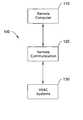
- FIG. 1shows a schematic block diagram of a system 100 for performing a method of the invention.
- the system 100includes a remote computer 110 communicating with an HVAC system 130 via remote communications block 120 .
- the HVAC system 130can be within a building structure and the remote computer 110 can be outside the building structure at a remote location.
- the remote computer 110can communicate with a plurality of HVAC systems 130 .
- the HVAC systems 130can provide test and/or maintenance information back to the remote computer 110 via the remote communications block 120 .
- the remote communications block 120is used particularly when there is a substantial physical distance between the remote computer 110 and the HVAC systems 130 .
- the remote computer 110can include any type of microprocessor capable of operating software useful with the methods described herein.
- the remote computer 110can include a personal computer having a central processing unit, a display monitor, and communication and connectivity means, such as a modem or internet connection.
- the remote computer 110can include any number of additional or other components such as data storage and data routing components, as desired.
- the remote computer 110may be a web server that, for example, can providing access and/or control via the Internet.
- the remote computer 110may be capable of transmitting one or more signals to one or a plurality of HVAC systems 130 via the remote communications block 120 .
- the remote computer 110may also be capable of receiving data from the one or plurality of HVAC systems 130 via the remote communications block 120 .
- the remote computer 110can also be capable of manipulating the received data and generating any number of output reports based on the received data.
- the remote computer 110can communicate with the plurality of HVAC systems 130 at the same time or each one sequentially, as desired.
- the remote communications block 120may provide communication between the remote computer 110 and the HVAC system 130 .
- the remote communications block 120can include and known or future communications technology, including but not limited to, wired communication such as fiber optic, cable, twisted pairs, and the like, or wireless communications such as radio, cellular, satellite, and the like.
- the remote communications block 120can be capable of bidirectional communication between the remote computer 110 and the HVAC system 130 .
- the HVAC systems 130can include one or more HVAC systems.
- the HVAC systemincludes 10, 20, 30, 50, 100, 1000, 10,000 or more HVAC systems.
- the HVAC systems 130can be residential and/or commercial HVAC systems.
- the HVAC systems 130can be selected from, for example, a customer database and grouped according to a geographic set of parameters such that all the of selected HVAC systems 130 are located with a specified geographic region.
- the HVAC systems 130can be selected from, for example, a customer database and grouped according to the type of HVAC system equipment, service level, the order that the HVAC systems are stored in the customer database, or any other suitable way.
- An illustrative embodiment of one of the HVAC systems 130is described below.
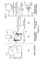
- FIG. 2is a schematic block diagram of an illustrative HVAC system 130 .
- the HVAC system 130includes a controller 131 , a HVAC unit 132 , and at least one interior climate controlled zone 133 , where the controller 131 is in communication with the remote communication block 120 .
- the controller 131may be coupled to the remote communication block 120 via interface 141 a and to the HVAC unit 132 via interface 141 b .
- the controller 131 , remote communication block 120 and the HVAC unit 132may communicate over a common wire or bus, such as bus 143 .
- the common wire or busmay be configured to be compatible with the ENVIRACOM® protocol, provided by the assignee of the present invention.
- the ENVIRACOM® protocolhelps HVAC appliances, thermostats, gateways and other components communicate with each other over a common bus.
- the controller 131can be any suitable controller, and in the illustrative embodiment, includes a microprocessor 135 , a display 136 and a memory 137 .
- the microprocessor 135may be capable of being programmed such that the controller 131 changes a control signal sent to the HVAC unit 132 based on the time of day, temperature, humidity, ventilation, or any other desired parameter.
- the display 136can provide parameter readings and/or set point information to the user.
- the memory 137can be embodied in a variety of forms such as, for example, read only memory can be used to retain operating and/or maintenance programs and predetermined values and random access memory can provide transitory working memory space, as desired.
- the foregoing elementscan be implemented by any suitable devices known in the art.
- the illustrative HVAC unit 132includes a heating component 139 and a cooling component 138 . In some cases, however, the HVAC unit 132 may only include a heating component, or only a cooling component, as desired.
- the heating component 139can include a gas heater and the cooling component 138 can include an air conditioning compressor, and both components may share a common fan.
- one of the HVAC unit components 138 , 139can be considered the active component and the remaining component may be considered the dormant component.
- the heating component 139may be deemed the active component and the cooling component 138 may be deemed the dormant component.
- the cooling component 138may be deemed the active component and the cooling component 139 may be deemed the dormant component.
- the dormant componentis the component not currently energized or was not the last component activated for at least one day, one week, one month, or longer.
- the active componentis the component that is either currently energized or was the last component activated.
- the fluide.g., air or water
- heated or cooled within the HVAC unit 132can be provided to one or more respective zones, one of which is represented as zone 133 in FIG. 2 .
- the interior climate controlled zone 133can include an environmental parameter sensor such as, for example, a temperature sensor 134 to monitor the effect of the treated fluid used for heating or cooling the air or thermal mass in the zone 133 .
- the temperature sensor 134is in communication with the controller 131 .
- a self-test, test request and/or maintenance algorithmcan be performed on the dormant HVAC component to determine if the dormant HVAC component requires maintenance.
- the self-test and/or maintenance algorithmcan evaluate any useful HVAC parameter such as, for example, heating or cooling capacity of the HVAC system for one or each zone, flame intensity, operating efficiency, and the like.
- FIG. 3is a schematic diagram of a system for performing a method of the invention.
- FIG. 3shows a home or building region 140 , a communications infrastructure region 150 , a data storage and routing region 160 , and a messaging and contractor access region 170 .
- the home or building region 140includes an HVAC unit 142 operably connected to a controller or gateway 143 .
- the gateway 143may be provided as a separate gateway unit, part of a thermostat, part of a modem, part of an HVAC controller, or part of any other suitable device, as desired.
- the HVAC unit 142performs climate control for home or building 141 .
- the controller or gateway 143is in communication with a data storage and routing region 160 via a communications infrastructure region 150 .
- the communications infrastructure region 150can include any usable form of communications such as, for example, cellular 151 , telephone, cable 153 , the internet, and the like.
- the communications infrastructure region 150can provide bi-directional communication between the controller or gateway 143 and the remote data storage and routing region 160 .
- the data storage and routing region 160is in communication with messaging and contractor access region 170 .
- the data storage and routing region 160can provide a secure and redundant database for the information transmitted to and from the home or building region 140 .
- This data storage and routing region 160can be accessed by the messaging and contractor access region 170 .
- the term “contractor”is presumed to denote an HVAC maintenance contractor or HVAC maintenance contractor company that can perform maintenance on the HVAC unit 142 located in the remote home or building region 140 .
- the term “contractor”may also include other entities such as HVAC manufacturers, OEMs and/or others that may access the messaging and contractor access region 170 , if desired.
- the messaging and contractor access region 170provides information to an HVAC contractor regarding the condition of the HVAC unit 142 in the home or building region 140 .
- the HVAC contractorcan access or receive this information via a contractor web access 171 site, a cell phone, a pager, a PDA 173 and/or a fax or email 174 , to list just a few.
- Softwarecan be operated to work with the information at the data storage and routing region 160 via a contractor software pipe 172 . This information can be displayed or accessed via the contractor web access 171 , if desired.
- more than one HVAC contractorcan have access and/or run their own software via one or more contractor software pipes 172 to utilize the information stored at the data storage and routing region 160 , as described in conjunction with FIG. 6 below.
- a plurality of home or building regions 140can communicate with the data storage and routing region 160 via the communications infrastructure region 150 .
- a test request or maintenance requestcan be transmitted from the messaging and contractor access region 170 and/or form the data storage and routing region 160 to any number of remote home or building regions 140 .
- results form this routinemay be transmitted back to the data storage and routing region 160 for contractor access via the messaging and contractor access region 170 .
- an HVAC contractorcan determine which HVAC units 142 need maintenance, and then schedule and perform the required maintenance.
- FIG. 4is a schematic block diagram of another illustrative system 200 in accordance with the present invention.
- the system 200can include a remote computer 210 communicating with a HVAC system gateway 240 via remote communications block 220 .
- the HVAC system gateway 240is connected via a wired or wireless connection to the HVAC system 230 .
- the remote computer 210can communicate with a plurality of HVAC system gateways 240 in some embodiments.
- the HVAC system 230can provide test and/or maintenance information back to the HVAC system gateway 240 and the HVAC system gateway 240 can communicate with the remote computer 210 via the remote communications block 220 .
- the remote computer 210 , remote communications block 220 , and HVAC system 230are described above.
- the HVAC system gateway 240can include a microprocessor and memory useful for storing and transmitting test and/or maintenance routines and/or algorithms that are initiated by the test request received from the remote computer 210 .
- the HVAC system gateway 240can also receive, store and transmit test and/or maintenance results from the HVAC system 230 to the remote computer 210 via the remote communications block 220 .
- the HVAC system gateway 240can be a commercially available component such as, for example, an ENVIRACOM component commercially available from the assignee of the present invention.
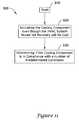
- FIG. 5is a block flow diagram of an illustrative method 300 in accordance with the present invention.
- the methodbegins at the start block 310 .
- Block 320transmits one or more test and/or maintenance signals to one or a plurality of HVAC systems from a remote computer or unit via a communications link.
- the plurality of HVAC systemscan be a specified group of remote HVAC systems chosen based on any number of parameters such as, for example, proximity to a geographic location.
- Block 330receives the test and/or maintenance signal at the plurality of HVAC systems.
- the HVAC systemcan include a gateway where the algorithms or test routine is stored and initiated by the test and/or maintenance request signal.
- Block 340performs a self-test and/or maintenance algorithm on the corresponding HVAC system.
- the self-test and/or maintenance algorithmcan be communicated from either the remote computer or from the HVAC gateway.
- the self-test and/or maintenance algorithmactivates a dormant HVAC component and determines the maintenance results.
- the step of performing the self-test and/or maintenance algorithmcan be executed at any useful time of day or delayed until a specified period of time such as when the home or building is expected to be unoccupied, or at night when the occupants are expected to be sleeping.
- Block 350transmits the self-test and/or maintenance results to the remote unit or computer via the remote communications link.
- the self-test and/or maintenance resultscan be transmitted from a microprocessor having memory and communication link as described above.
- the step of transmitting the self-test and/or maintenance results to the remote unit or computer via the remote communications linkcan be executed at any useful time of day or delayed for a specific period of time, as desired.
- the step of transmitting the self-test and/or maintenance results to the remote unit or computer via the remote communications linkcan be initiated by a retrieval signal transmitted by the remote computer and received by the HVAC system (or gateway).
- This retrieval signalcan be transmitted by the remote unit and received by the HVAC system (or gateway) at any time following the completion of the self-test and/or maintenance algorithm such as, for example, 12 hours, 1 day, 1 week or 1 month following the completion of the self-test and/or maintenance algorithm, as desired.
- Block 360receives the self-test and/or maintenance results from the plurality of HVAC systems at the remote unit or computer.
- the remote computercan store the self-test and/or maintenance results in memory, such as in RAM, on a hard disk, on a tape, etc.
- the remote computercan further generate reports based on the received self-test and/or maintenance results, and provide the results to the contractor, if desired.
- Block 370analyzes the received self-test and/or maintenance results, and schedules maintenance on HVAC systems in need of maintenance.
- FIG. 6is a schematic diagram of an illustrative embodiment of a contractor web access page 400 .
- the contractor web access page 400can correspond to the contractor web access icon 171 in FIG. 3 .
- the contractor web access page 400can be operated by software useful for managing a customer database and utilizing the data storage and routing information described above with reference to FIG. 3 .
- one or more contractors 415have a contractor page such as, for example, No. 1 Contractor Page 420 and No. “N” Contractor Page 410.
- Each contractor 415can access their contractor page via a common web access URL 430 and can enter a user name and password, if desired.
- Each contractor page 410 , 420can display information regarding its' HVAC maintenance customer base such as, for example, customer base statistics, reports, customer record management, communications status, and the like.
- Each contractor page 410 , 420can be linked to a customer base database 401 , 402 .
- Each customer base database 401 , 402can include information for each HVAC customer such as, for example, account number, address, alarm thresholds, messaging options, services configurations, communications link, and the like.
- the information provided in the customer records 401 , 402can be supplied for each customer HVAC unit.
- the customer base database 401 , 402can be located within the data storage and routing element described in FIG. 3 or the customer base database 401 , 402 can be in communication with the data storage and routing element described in FIG. 3 .
- Each contractor 415can use the data provided to determine which customer HVAC units require maintenance, and then perform the required maintenance.
- FIGS. 7 to 12are block flow diagrams of illustrative methods of the invention.
- FIG. 7is an illustrative method 500 for testing an HVAC system for a building structure from a remote location outside of the building structure, where the HVAC system has a primarily active component and a primarily dormant component.
- This methodbegins at the start block 510 .
- the methodincludes the step of transmitting a test request to the HVAC system from the remote location 520 .
- the methodincludes the step of performing a test on the primarily dormant component of the HVAC system in response to the test request to produce a test result 530 .
- the methodincludes the step of transmitting the test result to a location outside of the building structure 540 .
- the primarily active componentcan be either the heating or cooling component depending on whether it is currently the heating or cooling season, as described above.
- the primarily dormant componentcan be either the heating or cooling component depending on whether it is the heating or cooling season, as described above.
- the test requestcan be transmitted to the HVAC system from a remote computer via a telephone line connection, a wireless connection, a computer network, the internet, or any other suitable connection.
- the HVAC systemcan include a gateway for receiving the test request from the remote computer, and for communicating with the HVAC system.
- the gatewaycan store one or more tests, and can submit at least one of the one or more tests to the HVAC system in response to a test request.
- the gatewaycan select a subset of the one or more tests and submit the subset of the one or more tests to the HVAC system in response to the test request.
- the gatewaycan be within or proximate to the building structure serviced by HVAC system.
- the HVAC systemcan include two or more zones, and the test that is performed can activate the primarily dormant component in conjunction with each of the two or more zones.
- the transmitting stepcan transmit a test request to two or more HVAC systems from the remote location, as described above. Further, the test result for each HVAC system can be transmitted to a location outside of the building structure. In addition, the remote location that the test request is transmitted from can be the same as or different from the remote location that the test result is transmitted to.
- FIG. 8is another illustrative method 600 for testing a plurality of HVAC systems each in a different building structure from a remote location.
- This methodbegins at the start block 610 .
- the methodincludes the step of transmitting a test request to each of the plurality of HVAC systems from the remote location 620 .
- the methodincludes the step of performing one or more tests on each of the HVAC systems in response to the test request, and producing a test result for each of the HVAC systems 630 .
- the methodincludes the step of transmitting the test result for each of the HVAC systems to a remote location 640 .
- At least some of the plurality of HVAC systemsinclude a primarily active component and a primarily dormant component, and wherein at least one of the one or more tests that is performed activates and tests the primarily active component of the corresponding HVAC system in response to the test request.
- at least some of the plurality of HVAC systemsinclude a primarily active component and a primarily dormant component, and wherein at least one of the one or more tests that is performed activates and tests the primarily dormant component of the corresponding HVAC system in response to the test request.
- FIG. 9is yet another illustrative method for determining which of a plurality of HVAC systems will require maintenance 700 .
- This methodbegins at the start block 710 .
- This methodincludes the step of transmitting a test request to each of the plurality of HVAC systems from the remote location 720 .
- the next stepincludes performing one or more tests on at least selected ones of the HVAC systems in response to the test request, and producing a test result for each of the selected HVAC systems 730 .
- the methodincludes transmitting the test result for each of the selected HVAC systems to a remote location 740 .
- the methodincludes identifying which of the HVAC systems will likely need service by analyzing the test results 750 .
- This methodcan further include the step of providing different test requests to at least two of the plurality of HVAC systems, where each test request identifies a different test to perform.
- This methodcan further include the step of charging an owner of an HVAC system an amount that depends on the particular test that is performed on the HVAC system.
- this methodcan further include the step of scheduling service on at least some of the HVAC systems that have been identified as likely needing service.
- FIG. 10is another illustrative method for testing an HVAC system for an inside space prior to a heating season, where the HVAC system has a heating component 800 .
- the methodstarts a block 810 .
- This methodincludes the steps of activating the heating component even though the HVAC system would not normally call for heat 820 .
- This methodfurther includes the step of determining if the heating component is in compliance with a number of predetermined conditions or parameters 830 .
- the predetermined conditions or parameterscan include, for example, flame conditions, heating efficiency, and the like.
- a remote self-testcan cause the HVAC system (thermostat/controller) to set a temperature parameter in a particular heating zone and activate the heating cycle of the HVAC system.
- the HVAC systemcan monitor the HVAC response confirming that the space was heated within a specified time parameter. This sequence can be repeated for all zones within the building. When all zones have been tested, the HVAC system can report the results back to the HVAC contractor, if desired.
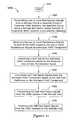
- FIG. 11is yet another illustrative method for testing an HVAC system for an inside space prior to a cooling season, where the HVAC system has a cooling component 900 .
- the methodstarts at block 910 .
- This methodincludes the steps of activating the cooling component even though the HVAC system would not normally call for cool 920 .
- This methodfurther includes the step of determining if the cooling component is in compliance with a number of predetermined conditions 930 .
- the predetermined conditionscan include, for example, condenser conditions, cooling efficiency, and the like.
- a remote self-testcan cause the HVAC system (thermostat/controller) to set a temperature parameter in a particular heating zone and activate the cooling cycle of the HVAC system.
- the HVAC systemcan monitor the HVAC response confirming that the space was cooled within a specified time parameter. This sequence can be repeated for all remaining zones within the building. When all zones have been tested, the HVAC system can report the results back to the HVAC contractor, if desired.
- FIG. 12is another illustrative method of remote testing of HVAC systems 1000 .
- the methodstarts at block 1010 .
- This methodincludes the step of transmitting one or more maintenance signals from a remote unit to a specified group of customer HVAC systems, where the specified group is a number less than a total number of customer HVAC systems in a customer database 1020 .
- the next stepis receiving the one or more maintenance signals at each of the HVAC systems, where the one or more maintenance signals activates an HVAC component 1030 .
- the methodincludes performing a self-test on the activated HVAC component based on the received one or more maintenance signal 1040 .
- the methodincludes generating self-test result signals from the activated HVAC component based on the self-test preformed on the activated HVAC component 1050 .
- the methodincludes transmitting the self-test result signals from the HVAC system to the remote unit 1060 .
- the methodincludes receiving the self-test result signals from the HVAC systems at the remote unit 1070 .
- This methodcan further include the step of determining the specified group of customer HVAC systems based on the specified group of customer HVAC systems being within a specified geographic area prior to the step of transmitting the one or more maintenance signals.
- This methodcan further include the step of determining which customer HVAC systems from the specified group of customer HVAC systems likely require maintenance based on the self-test signals received by the remote unit.
- this methodcan include the step of performing maintenance on the customer HVAC systems that are determined to likely require maintenance based on the self-test signals received by the remote unit.
Landscapes
- Engineering & Computer Science (AREA)
- General Engineering & Computer Science (AREA)
- General Physics & Mathematics (AREA)
- Physics & Mathematics (AREA)
- Chemical & Material Sciences (AREA)
- Combustion & Propulsion (AREA)
- Mechanical Engineering (AREA)
- Theoretical Computer Science (AREA)
- Automation & Control Theory (AREA)
- Computing Systems (AREA)
- Quality & Reliability (AREA)
- Human Computer Interaction (AREA)
- Air Conditioning Control Device (AREA)
- Mobile Radio Communication Systems (AREA)
Abstract
Description
Claims (34)
Priority Applications (5)
| Application Number | Priority Date | Filing Date | Title |
|---|---|---|---|
| US10/822,882US8332178B2 (en) | 2004-04-13 | 2004-04-13 | Remote testing of HVAC systems |
| PCT/US2005/012617WO2005100874A2 (en) | 2004-04-13 | 2005-04-13 | Remote testing of hvac systems |
| US13/673,756US8589111B2 (en) | 2004-04-13 | 2012-11-09 | Remote testing of HVAC systems |
| US14/048,691US9411703B2 (en) | 2004-04-13 | 2013-10-08 | Remote testing of HVAC systems |
| US15/224,171US10571903B2 (en) | 2004-04-13 | 2016-07-29 | Remote testing of HVAC systems |
Applications Claiming Priority (1)
| Application Number | Priority Date | Filing Date | Title |
|---|---|---|---|
| US10/822,882US8332178B2 (en) | 2004-04-13 | 2004-04-13 | Remote testing of HVAC systems |
Related Child Applications (1)
| Application Number | Title | Priority Date | Filing Date |
|---|---|---|---|
| US13/673,756ContinuationUS8589111B2 (en) | 2004-04-13 | 2012-11-09 | Remote testing of HVAC systems |
Publications (2)
| Publication Number | Publication Date |
|---|---|
| US20050228607A1 US20050228607A1 (en) | 2005-10-13 |
| US8332178B2true US8332178B2 (en) | 2012-12-11 |
Family
ID=34965666
Family Applications (4)
| Application Number | Title | Priority Date | Filing Date |
|---|---|---|---|
| US10/822,882Active2030-03-20US8332178B2 (en) | 2004-04-13 | 2004-04-13 | Remote testing of HVAC systems |
| US13/673,756Expired - LifetimeUS8589111B2 (en) | 2004-04-13 | 2012-11-09 | Remote testing of HVAC systems |
| US14/048,691Expired - LifetimeUS9411703B2 (en) | 2004-04-13 | 2013-10-08 | Remote testing of HVAC systems |
| US15/224,171Active2026-04-18US10571903B2 (en) | 2004-04-13 | 2016-07-29 | Remote testing of HVAC systems |
Family Applications After (3)
| Application Number | Title | Priority Date | Filing Date |
|---|---|---|---|
| US13/673,756Expired - LifetimeUS8589111B2 (en) | 2004-04-13 | 2012-11-09 | Remote testing of HVAC systems |
| US14/048,691Expired - LifetimeUS9411703B2 (en) | 2004-04-13 | 2013-10-08 | Remote testing of HVAC systems |
| US15/224,171Active2026-04-18US10571903B2 (en) | 2004-04-13 | 2016-07-29 | Remote testing of HVAC systems |
Country Status (2)
| Country | Link |
|---|---|
| US (4) | US8332178B2 (en) |
| WO (1) | WO2005100874A2 (en) |
Cited By (14)
| Publication number | Priority date | Publication date | Assignee | Title |
|---|---|---|---|---|
| US20060198208A1 (en)* | 2005-03-07 | 2006-09-07 | Lantronix, Inc. | Publicasting systems and methods |
| US8589111B2 (en) | 2004-04-13 | 2013-11-19 | Honeywell International Inc. | Remote testing of HVAC systems |
| US20140032157A1 (en)* | 2012-07-24 | 2014-01-30 | Lennox Industries, Inc. | Programmed triggering of diagnostics for a space conditioning system |
| US8870086B2 (en) | 2004-03-02 | 2014-10-28 | Honeywell International Inc. | Wireless controller with gateway |
| US20150127167A1 (en)* | 2013-11-04 | 2015-05-07 | Honeywell International Inc. | Remote contractor system with summary display screen |
| US10094585B2 (en) | 2013-01-25 | 2018-10-09 | Honeywell International Inc. | Auto test for delta T diagnostics in an HVAC system |
| US10139122B2 (en) | 2015-01-26 | 2018-11-27 | Trane International Inc. | Diagnostic data bus for acquiring and communicating diagnostic information from HVAC systems |
| US10145578B2 (en) | 2006-11-30 | 2018-12-04 | Honeywell International Inc. | HVAC controller with checkout utility |
| US10812285B2 (en) | 2016-02-16 | 2020-10-20 | Ademco Inc. | Systems and methods for handing off configuration of a building device from a contractor to a customer |
| US10820199B2 (en) | 2016-02-16 | 2020-10-27 | Ademco Inc. | Mobile device with contractor accessible screens for configuring a building device |
| US10989427B2 (en) | 2017-12-20 | 2021-04-27 | Trane International Inc. | HVAC system including smart diagnostic capabilites |
| US11237528B2 (en) | 2016-02-16 | 2022-02-01 | Ademco Inc. | System and method for handing off the configuration of a building device from a contractor to a customer using a hang tag or the like |
| US11639804B2 (en) | 2019-12-13 | 2023-05-02 | Trane International Inc. | Automated testing of HVAC devices |
| US11713895B2 (en) | 2019-01-14 | 2023-08-01 | Research Products Corporation | Multi-zone environmental control system |
Families Citing this family (51)
| Publication number | Priority date | Publication date | Assignee | Title |
|---|---|---|---|---|
| US7412842B2 (en) | 2004-04-27 | 2008-08-19 | Emerson Climate Technologies, Inc. | Compressor diagnostic and protection system |
| US7275377B2 (en) | 2004-08-11 | 2007-10-02 | Lawrence Kates | Method and apparatus for monitoring refrigerant-cycle systems |
| KR20060054840A (en)* | 2004-11-16 | 2006-05-23 | 엘지전자 주식회사 | Outdoor unit software upgrade system and method |
| US7299111B2 (en)* | 2005-02-04 | 2007-11-20 | Johnson Controls Technology Company | Method of clearing an HVAC control fault code memory |
| US7562536B2 (en)* | 2005-03-02 | 2009-07-21 | York International Corporation | Method and apparatus to sense and control compressor operation in an HVAC system |
| US20070208461A1 (en)* | 2006-03-01 | 2007-09-06 | Johnson Controls Technology Company | Hvac control with programmed run-test sequence |
| US8590325B2 (en) | 2006-07-19 | 2013-11-26 | Emerson Climate Technologies, Inc. | Protection and diagnostic module for a refrigeration system |
| US20080216494A1 (en) | 2006-09-07 | 2008-09-11 | Pham Hung M | Compressor data module |
| US20080128523A1 (en)* | 2006-11-30 | 2008-06-05 | Honeywell International Inc. | Hvac zone control panel |
| US7693591B2 (en)* | 2006-11-30 | 2010-04-06 | Honeywell International Inc. | HVAC zone control panel with checkout utility |
| US7913180B2 (en)* | 2006-11-30 | 2011-03-22 | Honeywell International Inc. | HVAC zone control panel with mode navigation |
| US7693583B2 (en)* | 2006-11-30 | 2010-04-06 | Honeywell International Inc. | HVAC zone control panel with constant function buttons |
| US7957839B2 (en) | 2006-12-29 | 2011-06-07 | Honeywell International Inc. | HVAC zone controller |
| US7766246B2 (en)* | 2007-03-15 | 2010-08-03 | Honeywell International Inc. | Variable speed blower control in an HVAC system having a plurality of zones |
| US7819331B2 (en)* | 2007-04-13 | 2010-10-26 | Honeywell International Inc. | HVAC staging control |
| US20090037142A1 (en) | 2007-07-30 | 2009-02-05 | Lawrence Kates | Portable method and apparatus for monitoring refrigerant-cycle systems |
| US9140728B2 (en) | 2007-11-02 | 2015-09-22 | Emerson Climate Technologies, Inc. | Compressor sensor module |
| US20100114382A1 (en)* | 2008-11-05 | 2010-05-06 | Computime, Ltd. | Determination of the Type of Heaving, Ventilating, and Air Conditioning (HVAC) System |
| US8718707B2 (en)* | 2009-03-20 | 2014-05-06 | Johnson Controls Technology Company | Devices, systems, and methods for communicating with rooftop air handling units and other HVAC components |
| CA2934860C (en) | 2011-02-28 | 2018-07-31 | Emerson Electric Co. | Residential solutions hvac monitoring and diagnosis |
| US8950688B2 (en)* | 2011-06-16 | 2015-02-10 | Honeywell International, Inc. | Apparatus and method for self-test of thermostat |
| US8964338B2 (en) | 2012-01-11 | 2015-02-24 | Emerson Climate Technologies, Inc. | System and method for compressor motor protection |
| US9244469B2 (en)* | 2012-05-15 | 2016-01-26 | Siemens Industry, Inc. | Automated HVAC system functionality test |
| US10992494B2 (en) | 2012-09-15 | 2021-04-27 | Ademco Inc. | Gateway round-robin system |
| US9122255B2 (en) | 2012-09-15 | 2015-09-01 | Honeywell International Inc. | Remote access gateway configurable control system |
| US9705962B2 (en) | 2012-09-15 | 2017-07-11 | Honeywell International Inc. | Asynchronous reporting system |
| US10514713B2 (en) | 2012-09-15 | 2019-12-24 | Ademco Inc. | Mailbox data storage system |
| US9310439B2 (en) | 2012-09-25 | 2016-04-12 | Emerson Climate Technologies, Inc. | Compressor having a control and diagnostic module |
| US20140200718A1 (en)* | 2013-01-16 | 2014-07-17 | Honeywell International Inc. | Systems and methods for facilitating diagnostic testing of an hvac system |
| US9551504B2 (en) | 2013-03-15 | 2017-01-24 | Emerson Electric Co. | HVAC system remote monitoring and diagnosis |
| EP2971989A4 (en) | 2013-03-15 | 2016-11-30 | Emerson Electric Co | DIAGNOSTICS AND SYSTEM FOR HEATING, VENTILATION AND AIR CONDITIONING REMOTE MONITORING |
| US9803902B2 (en) | 2013-03-15 | 2017-10-31 | Emerson Climate Technologies, Inc. | System for refrigerant charge verification using two condenser coil temperatures |
| WO2014165731A1 (en) | 2013-04-05 | 2014-10-09 | Emerson Electric Co. | Heat-pump system with refrigerant charge diagnostics |
| CN104235998A (en)* | 2013-06-13 | 2014-12-24 | 上海能感物联网有限公司 | Method for non-specified people to remotely control intelligent air conditioner through Chinese phonetic symbols |
| US20160148484A1 (en)* | 2013-07-22 | 2016-05-26 | Rohm Co., Ltd. | Warning system for use in daily life |
| CA2929709C (en)* | 2015-05-15 | 2023-09-26 | Watsco Ventures Llc | Method and system for proactively and remotely diagnosing an hvac system |
| DK3303949T3 (en)* | 2015-06-01 | 2020-08-31 | Carrier Corp | Load-neutral diagnostic system, climate-controlled mobile cargo container with a load-neutral diagnostic system and procedure |
| CN104990207B (en)* | 2015-06-10 | 2017-10-31 | 浙江大学 | A kind of dynamic self-adapting air-conditioner control system |
| US10663190B2 (en) | 2015-07-28 | 2020-05-26 | Mitsubishi Electric Corporation | Determination assistance device, determination assistance method, and program |
| US20170051932A1 (en)* | 2015-08-20 | 2017-02-23 | Honeywell International Inc. | Adaptive user interface for an hvac system |
| US10724752B2 (en)* | 2016-05-24 | 2020-07-28 | Gridpoint, Inc. | Methods and systems for automated HVAC testing |
| CN106124232B (en)* | 2016-06-13 | 2018-11-06 | 合肥市再德高分子材料有限公司 | A kind of central air-conditioning intelligence detecting system |
| BR112019017228B1 (en)* | 2017-04-07 | 2022-08-23 | Daikin Industries, Ltd | AIR CONDITIONING CONTROL SYSTEM |
| WO2019097613A1 (en)* | 2017-11-15 | 2019-05-23 | 三菱電機株式会社 | Air-conditioning management system, air conditioner, air-conditioning management device, air-conditioning management method, and program |
| JP6955231B2 (en)* | 2019-12-10 | 2021-10-27 | ダイキン工業株式会社 | Maintenance support system |
| US11193692B2 (en) | 2020-03-30 | 2021-12-07 | Lennox Industries Inc. | HVAC system prognostics |
| US11994303B2 (en)* | 2020-05-12 | 2024-05-28 | Watts Regulator Co. | Smart thermostat and a thermostat adapter with integrated safety interlock for installation and diagnostics of an in-floor heating system |
| US12105491B2 (en)* | 2020-12-18 | 2024-10-01 | Tyco Fire & Security Gmbh | VAV self commissioning in a building automation system |
| US11530835B2 (en) | 2021-02-25 | 2022-12-20 | Siemens Industry, Inc. | System for preventive maintenance of HVAC units |
| CN118534872B (en)* | 2024-04-30 | 2025-03-18 | 广州成业机电设备制造有限公司 | All-in-one HVAC electronic control component intelligent test system, test method, electronic equipment and storage medium |
| CN119310976B (en)* | 2024-12-19 | 2025-02-28 | 广东汇龙电器有限公司 | Intelligent temperature controller durability test system |
Citations (68)
| Publication number | Priority date | Publication date | Assignee | Title |
|---|---|---|---|---|
| US4016360A (en) | 1974-12-31 | 1977-04-05 | Mario Cane | System for remotely checking equipment |
| US4920263A (en) | 1988-01-26 | 1990-04-24 | Gemini Research, Inc. | Radon detection system |
| US5042265A (en)* | 1990-07-16 | 1991-08-27 | American Standard Inc. | Controlling HVAC test functions |
| US5191874A (en) | 1991-06-13 | 1993-03-09 | Mcwilliams Oliver B | Heavy gas, including radon gas, expeller assembly |
| US5197862A (en) | 1992-02-10 | 1993-03-30 | Kladder Douglas L | Method and device for monitoring radon mitigation system |
| US5388444A (en) | 1993-10-06 | 1995-02-14 | Gerard; Thomas J. | Apparatus and methods for determining required vacuum characteristics of a radon evacuation system |
| US5495722A (en) | 1994-04-21 | 1996-03-05 | Whirlpool Corporation | Remote control for diagnostics of an air conditioner |
| US5551797A (en) | 1995-02-17 | 1996-09-03 | Sanford; Paul C. | Underground drainage sump system and method of retrofitting for protecting a floor slab |
| US5729474A (en) | 1994-12-09 | 1998-03-17 | Excel Energy Technologies, Ltd. | Method of anticipating potential HVAC failure |
| US5761649A (en) | 1992-04-10 | 1998-06-02 | Charles E. Hill & Associates, Inc. | Method for updating a remote computer |
| EP0848215A2 (en) | 1996-12-12 | 1998-06-17 | Mitsubishi Denki Kabushiki Kaisha | Remote monitoring system of cooling apparatus |
| US5836815A (en) | 1997-06-27 | 1998-11-17 | Jennemann; Paul V. | Method and system for radon mitigation |
| US5997476A (en) | 1997-03-28 | 1999-12-07 | Health Hero Network, Inc. | Networked system for interactive communication and remote monitoring of individuals |
| WO1999065192A1 (en) | 1998-06-08 | 1999-12-16 | Telefonaktiebolaget Lm Ericsson (Publ) | Application and communication platform for connectivity based services |
| WO2000001169A1 (en) | 1998-06-29 | 2000-01-06 | Telefonaktiebolaget Lm Ericsson (Publ) | Method and arrangement relating to intelligent network services |
| US6088688A (en) | 1997-12-17 | 2000-07-11 | Avista Advantage, Inc. | Computerized resource accounting methods and systems, computerized utility management methods and systems, multi-user utility management methods and systems, and energy-consumption-based tracking methods and systems |
| US6167766B1 (en) | 1996-10-18 | 2001-01-02 | Westinghouse Savannah River Company | Programmable atmospheric sampling systems and methods |
| US6175934B1 (en) | 1997-12-15 | 2001-01-16 | General Electric Company | Method and apparatus for enhanced service quality through remote diagnostics |
| US6282454B1 (en) | 1997-09-10 | 2001-08-28 | Schneider Automation Inc. | Web interface to a programmable controller |
| JP2002044750A (en) | 2000-07-25 | 2002-02-08 | Asahi Kasei Corp | Equipment monitoring system |
| EP1196002A2 (en)* | 2000-10-05 | 2002-04-10 | Carrier Corporation | Method for wireless remote controlling of HVRAC appliances |
| US6385510B1 (en)* | 1997-12-03 | 2002-05-07 | Klaus D. Hoog | HVAC remote monitoring system |
| US20020095323A1 (en) | 2001-01-12 | 2002-07-18 | Richard Combs | Automated building service broker |
| US20020095269A1 (en) | 2001-01-17 | 2002-07-18 | Francesco Natalini | System for monitoring and servicing appliances |
| US20020113877A1 (en) | 2001-02-20 | 2002-08-22 | Welch Patrick J. | System and method for remote monitoring and maintenance management of vertical transportation equipment |
| US20020147806A1 (en) | 2001-04-06 | 2002-10-10 | Yokogawa Electric Corporation | Remote maintenance system and data processing system using electronic mail |
| US20020147804A1 (en) | 2001-03-12 | 2002-10-10 | Michel Cosmao | System and method of remote maintenance management, corresponding management assembly and corresponding software product |
| US6467054B1 (en) | 1995-03-13 | 2002-10-15 | Compaq Computer Corporation | Self test for storage device |
| US20020183978A1 (en) | 2001-05-02 | 2002-12-05 | Kiyohisa Koyama | Remote maintenance and diagnosis of office or domestic appliances |
| US20020183880A1 (en) | 2001-05-31 | 2002-12-05 | Juntaro Arima | Remote maintenance method, industrial device, and semiconductor device |
| US6493425B1 (en) | 1998-09-09 | 2002-12-10 | Verizon Corporate Services Group Inc. | Method and system for testing a network element within a telecommunications network |
| US6496858B1 (en) | 1997-07-14 | 2002-12-17 | Tut Systems, Inc. | Remote reconfiguration of a secure network interface |
| US20020198990A1 (en) | 2001-06-25 | 2002-12-26 | Bradfield William T. | System and method for remotely monitoring and controlling devices |
| US20030034898A1 (en) | 2001-08-20 | 2003-02-20 | Shamoon Charles G. | Thermostat and remote control system and method |
| US6535838B2 (en) | 2000-01-28 | 2003-03-18 | Robertshaw Controls Company | Furnace diagnostic system |
| US6539499B1 (en) | 1999-10-06 | 2003-03-25 | Dell Usa, L.P. | Graphical interface, method, and system for the provision of diagnostic and support services in a computer system |
| US6557054B2 (en) | 1994-05-31 | 2003-04-29 | Richard R. Reisman | Method and system for distributing updates by presenting directory of software available for user installation that is not already installed on user station |
| US20030101262A1 (en) | 2001-11-27 | 2003-05-29 | Isochron Data Corporation | Method and system for scheduling the maintenance of remotely monitored devices |
| US6574672B1 (en) | 1999-03-29 | 2003-06-03 | Siemens Dematic Postal Automation, L.P. | System, apparatus and method for providing a portable customizable maintenance support computer communications system |
| US20030110001A1 (en) | 2001-12-12 | 2003-06-12 | Chassin David P. | Rooftop package unit diagnostician |
| US6584113B1 (en) | 1999-12-22 | 2003-06-24 | Pitney Bowes Inc. | Data transfer module and system using same |
| US6584430B1 (en) | 1997-07-21 | 2003-06-24 | Bio Rad Laboratories, Inc. | System and method for device monitoring |
| US20030140090A1 (en) | 2000-09-06 | 2003-07-24 | Babak Rezvani | Automated upload of content based on captured event |
| US6601086B1 (en) | 2000-06-06 | 2003-07-29 | Emware, Inc. | Service provider for providing data, applications and services to embedded devices and for facilitating control and monitoring of embedded devices |
| US20030176989A1 (en) | 2002-03-12 | 2003-09-18 | Tokyo Electron Limited | Method for collecting remote maintenance and diagnostic data from subject equipment, other device and manufacturing execution system |
| US20030195640A1 (en)* | 2002-04-16 | 2003-10-16 | Krocker Robert E. | HVAC service tool with internet capability |
| US6643611B1 (en) | 2000-05-11 | 2003-11-04 | Makoto Ito | Service system for air conditioner and server system for monitoring center |
| US6658586B1 (en) | 1999-10-07 | 2003-12-02 | Andrew E. Levi | Method and system for device status tracking |
| US6697894B1 (en) | 1999-03-29 | 2004-02-24 | Siemens Dematic Postal Automation, L.P. | System, apparatus and method for providing maintenance instructions to a user at a remote location |
| US6711470B1 (en) | 2000-11-16 | 2004-03-23 | Bechtel Bwxt Idaho, Llc | Method, system and apparatus for monitoring and adjusting the quality of indoor air |
| US6754707B2 (en) | 1999-10-28 | 2004-06-22 | Supportsoft, Inc. | Secure computer support system |
| US20040133314A1 (en) | 2002-03-28 | 2004-07-08 | Ehlers Gregory A. | System and method of controlling an HVAC system |
| US6782345B1 (en) | 2000-10-03 | 2004-08-24 | Xerox Corporation | Systems and methods for diagnosing electronic systems |
| US6792321B2 (en) | 2000-03-02 | 2004-09-14 | Electro Standards Laboratories | Remote web-based control |
| US20040232345A1 (en) | 2003-03-31 | 2004-11-25 | Pillalamarri Jagam | Continuous monitoring radon detector |
| US6826512B2 (en) | 2001-06-28 | 2004-11-30 | Sony Corporation | Using local devices as diagnostic tools for consumer electronic devices |
| US6832199B1 (en) | 1998-11-25 | 2004-12-14 | Ge Medical Technology Services, Inc. | Method and apparatus for retrieving service task lists from remotely located medical diagnostic systems and inputting such data into specific locations on a table |
| US6836737B2 (en) | 2000-08-09 | 2004-12-28 | Statsignal Systems, Inc. | Systems and methods for providing remote monitoring of consumption for a utility meter |
| US6847916B1 (en) | 2000-06-12 | 2005-01-25 | I/O Controls Corporation | Method and system for monitoring, controlling, and locating portable devices performing remote diagnostic analysis of control network |
| US6854010B1 (en) | 2001-04-05 | 2005-02-08 | Bluecube Software, Inc. | Multi-location management system |
| US6853958B1 (en) | 2000-06-30 | 2005-02-08 | Integrex | System and method for collecting and disseminating household information and for coordinating repair and maintenance services |
| US6857013B2 (en) | 1999-01-29 | 2005-02-15 | Intermec Ip.Corp. | Remote anomaly diagnosis and reconfiguration of an automatic data collection device platform over a telecommunications network |
| US6891838B1 (en) | 1998-06-22 | 2005-05-10 | Statsignal Ipc, Llc | System and method for monitoring and controlling residential devices |
| US6892225B1 (en) | 2000-07-19 | 2005-05-10 | Fusionone, Inc. | Agent system for a secure remote access system |
| US20050130652A1 (en) | 2003-06-24 | 2005-06-16 | O'toole Arthur J. | Wireless control for creation of, and command response to, standard freight shipment messages |
| US20050164678A1 (en) | 2000-11-28 | 2005-07-28 | Xanboo, Inc. | Method and system for communicating with a wireless device |
| US20060149414A1 (en) | 2004-12-30 | 2006-07-06 | Carrier Corporation | Remote web access control of multiple home comfort systems |
| US7092794B1 (en)* | 2000-10-05 | 2006-08-15 | Carrier Corporation | Method and apparatus for connecting to HVAC device |
Family Cites Families (53)
| Publication number | Priority date | Publication date | Assignee | Title |
|---|---|---|---|---|
| US5279458A (en)* | 1991-08-12 | 1994-01-18 | Carrier Corporation | Network management control |
| US6175931B1 (en) | 1997-01-31 | 2001-01-16 | Hewlett-Packard Company | Global hard error distribution using the SCI interconnect |
| US5907476A (en) | 1997-08-29 | 1999-05-25 | Allen-Bradley Company, Llc | Self-locking rail securement device |
| US20020087332A1 (en) | 2000-12-29 | 2002-07-04 | Brian Como | System and method for a contractor locator |
| CA2432440C (en) | 2001-01-12 | 2007-03-27 | Novar Controls Corporation | Small building automation control system |
| US7054822B2 (en) | 2001-08-06 | 2006-05-30 | Ecolab, Inc. | Notification of time-critical situations occurring at destination facilities |
| US7505914B2 (en) | 2001-08-06 | 2009-03-17 | Ecolab Inc. | Method and system for providing advisory information to a field service provider |
| US6778745B2 (en) | 2001-08-23 | 2004-08-17 | Fitel Usa Corp. | Optical fiber cable apparatus having encased ribbon stack |
| US6853882B2 (en)* | 2002-05-17 | 2005-02-08 | Carrier Corporation | HVAC system monitoring |
| US7337191B2 (en) | 2002-07-27 | 2008-02-26 | Siemens Building Technologies, Inc. | Method and system for obtaining service related information about equipment located at a plurality of sites |
| US8332178B2 (en) | 2004-04-13 | 2012-12-11 | Honeywell International Inc. | Remote testing of HVAC systems |
| US7296426B2 (en) | 2005-02-23 | 2007-11-20 | Emerson Electric Co. | Interactive control system for an HVAC system |
| US7434742B2 (en) | 2005-06-20 | 2008-10-14 | Emerson Electric Co. | Thermostat capable of displaying received information |
| US8001219B2 (en) | 2006-03-16 | 2011-08-16 | Exceptional Innovation, Llc | User control interface for convergence and automation system |
| US20070232288A1 (en) | 2006-03-30 | 2007-10-04 | Mcfarland Norman R | Service tool for wireless automation systems |
| US7571865B2 (en) | 2006-10-31 | 2009-08-11 | Tonerhead, Inc. | Wireless temperature control system |
| US7877305B2 (en) | 2007-03-01 | 2011-01-25 | Code Blue, Llc | System and method for automatically monitoring the performance of a contractor in the management of an insurance claim |
| US7653443B2 (en) | 2007-03-01 | 2010-01-26 | Daniel Flohr | Methods, systems, circuits and computer program products for electrical service demand management |
| US8200527B1 (en) | 2007-04-25 | 2012-06-12 | Convergys Cmg Utah, Inc. | Method for prioritizing and presenting recommendations regarding organizaion's customer care capabilities |
| US8239922B2 (en) | 2007-08-27 | 2012-08-07 | Honeywell International Inc. | Remote HVAC control with user privilege setup |
| US8099194B2 (en) | 2007-11-19 | 2012-01-17 | Prenova, Inc. | Demand control |
| US8219249B2 (en) | 2008-09-15 | 2012-07-10 | Johnson Controls Technology Company | Indoor air quality controllers and user interfaces |
| US8239066B2 (en) | 2008-10-27 | 2012-08-07 | Lennox Industries Inc. | System and method of use for a user interface dashboard of a heating, ventilation and air conditioning network |
| US8155900B1 (en) | 2009-01-29 | 2012-04-10 | Comverge, Inc. | Method and system for calculating energy metrics of a building and one or more zones within the building |
| BRPI1012188B1 (en) | 2009-05-08 | 2020-10-27 | Accenture Global Services Limited | computer implemented method for energy analysis and energy analysis system. |
| US8532839B2 (en) | 2009-06-22 | 2013-09-10 | Johnson Controls Technology Company | Systems and methods for statistical control and fault detection in a building management system |
| US8321188B2 (en) | 2009-11-18 | 2012-11-27 | Bank Of America Corporation | Weather-related energy-usage analysis |
| CN102812303B (en) | 2009-12-16 | 2016-03-30 | 国家科学和工业研究组织 | HVAC control system and method |
| US20110190910A1 (en) | 2010-02-03 | 2011-08-04 | Ecobee Inc. | System and method for web-enabled enterprise environment control and energy management |
| US20120016779A1 (en) | 2010-07-13 | 2012-01-19 | Landry Kenneth Troy | System and method for assisting a contractor to efficiently service an equipment |
| US8510255B2 (en) | 2010-09-14 | 2013-08-13 | Nest Labs, Inc. | Occupancy pattern detection, estimation and prediction |
| US8606374B2 (en) | 2010-09-14 | 2013-12-10 | Nest Labs, Inc. | Thermodynamic modeling for enclosures |
| CN107065961B (en) | 2010-12-31 | 2020-06-16 | 谷歌有限责任公司 | Flexible functional partitioning of intelligent thermostat controlled HVAC systems |
| US20120176252A1 (en) | 2011-01-12 | 2012-07-12 | Emerson Electric Co. | Apparatus and Method for Determining Load of Energy Consuming Appliances Within a Premises |
| US20120203586A1 (en) | 2011-02-07 | 2012-08-09 | FreeFieldService.com | Field Service Networking Platform |
| CA2934860C (en) | 2011-02-28 | 2018-07-31 | Emerson Electric Co. | Residential solutions hvac monitoring and diagnosis |
| US8620632B2 (en) | 2011-06-24 | 2013-12-31 | International Business Machines Corporation | Estimating building thermal properties by integrating heat transfer inversion model with clustering and regression techniques for a portfolio of existing buildings |
| US20130138475A1 (en) | 2011-11-30 | 2013-05-30 | G. Austin Allison | Systems and methods for transaction-based sales lead generation |
| US9261863B2 (en) | 2012-01-23 | 2016-02-16 | Earth Networks, Inc. | Optimizing and controlling the energy consumption of a building |
| CA2865697C (en) | 2012-02-28 | 2018-01-09 | Jeffrey N. Arensmeier | Hvac system remote monitoring and diagnosis |
| US20130332306A1 (en) | 2012-06-12 | 2013-12-12 | Ecobee Inc. | Hvac controller with installer rating feature |
| US8554376B1 (en) | 2012-09-30 | 2013-10-08 | Nest Labs, Inc | Intelligent controller for an environmental control system |
| US20140172479A1 (en) | 2012-12-14 | 2014-06-19 | Lisa A. Gallagher | Integrated Customer Profiling, Service Provider Matching and Smart Order, Creation System and Method |
| US9807099B2 (en) | 2013-03-15 | 2017-10-31 | Google Inc. | Utility portals for managing demand-response events |
| US20140279571A1 (en) | 2013-03-15 | 2014-09-18 | Emerson Electric Co. | Contractor locator and dispatch service |
| EP2971989A4 (en) | 2013-03-15 | 2016-11-30 | Emerson Electric Co | DIAGNOSTICS AND SYSTEM FOR HEATING, VENTILATION AND AIR CONDITIONING REMOTE MONITORING |
| AU2014233918B2 (en) | 2013-03-15 | 2017-05-25 | Emerson Electric Co. | Contractor locator, dispatch, scheduling, and component purchasing service |
| US10204182B2 (en) | 2013-04-01 | 2019-02-12 | Ademco, Inc. | System for obtaining and classifying energy characteristics |
| US20140337082A1 (en) | 2013-04-04 | 2014-11-13 | Jorj Nofal | Energy audit tool |
| US9910449B2 (en) | 2013-04-19 | 2018-03-06 | Google Llc | Generating and implementing thermodynamic models of a structure |
| US20140379298A1 (en) | 2013-06-21 | 2014-12-25 | Apogee Interactive, Inc. | Systems and Methods for Monitoring Energy Usage via Thermostat-Centered Approaches and Deriving Building Climate Analytics |
| US20150006125A1 (en) | 2013-06-28 | 2015-01-01 | International Business Machines Corporation | Inverse modeling procedure for building energy using integrated pde-ode models and stepwise parameter estimation |
| US10139123B2 (en) | 2013-11-04 | 2018-11-27 | Honeywell International Inc. | Remote contractor system with summary display screen |
- 2004
- 2004-04-13USUS10/822,882patent/US8332178B2/enactiveActive
- 2005
- 2005-04-13WOPCT/US2005/012617patent/WO2005100874A2/enactiveApplication Filing
- 2012
- 2012-11-09USUS13/673,756patent/US8589111B2/ennot_activeExpired - Lifetime
- 2013
- 2013-10-08USUS14/048,691patent/US9411703B2/ennot_activeExpired - Lifetime
- 2016
- 2016-07-29USUS15/224,171patent/US10571903B2/enactiveActive
Patent Citations (71)
| Publication number | Priority date | Publication date | Assignee | Title |
|---|---|---|---|---|
| US4016360A (en) | 1974-12-31 | 1977-04-05 | Mario Cane | System for remotely checking equipment |
| US4920263A (en) | 1988-01-26 | 1990-04-24 | Gemini Research, Inc. | Radon detection system |
| US5042265A (en)* | 1990-07-16 | 1991-08-27 | American Standard Inc. | Controlling HVAC test functions |
| US5191874A (en) | 1991-06-13 | 1993-03-09 | Mcwilliams Oliver B | Heavy gas, including radon gas, expeller assembly |
| US5197862A (en) | 1992-02-10 | 1993-03-30 | Kladder Douglas L | Method and device for monitoring radon mitigation system |
| US5761649A (en) | 1992-04-10 | 1998-06-02 | Charles E. Hill & Associates, Inc. | Method for updating a remote computer |
| US5388444A (en) | 1993-10-06 | 1995-02-14 | Gerard; Thomas J. | Apparatus and methods for determining required vacuum characteristics of a radon evacuation system |
| US5495722A (en) | 1994-04-21 | 1996-03-05 | Whirlpool Corporation | Remote control for diagnostics of an air conditioner |
| US6557054B2 (en) | 1994-05-31 | 2003-04-29 | Richard R. Reisman | Method and system for distributing updates by presenting directory of software available for user installation that is not already installed on user station |
| US5729474A (en) | 1994-12-09 | 1998-03-17 | Excel Energy Technologies, Ltd. | Method of anticipating potential HVAC failure |
| US5551797A (en) | 1995-02-17 | 1996-09-03 | Sanford; Paul C. | Underground drainage sump system and method of retrofitting for protecting a floor slab |
| US6467054B1 (en) | 1995-03-13 | 2002-10-15 | Compaq Computer Corporation | Self test for storage device |
| US6167766B1 (en) | 1996-10-18 | 2001-01-02 | Westinghouse Savannah River Company | Programmable atmospheric sampling systems and methods |
| EP0848215A2 (en) | 1996-12-12 | 1998-06-17 | Mitsubishi Denki Kabushiki Kaisha | Remote monitoring system of cooling apparatus |
| US5997476A (en) | 1997-03-28 | 1999-12-07 | Health Hero Network, Inc. | Networked system for interactive communication and remote monitoring of individuals |
| US5836815A (en) | 1997-06-27 | 1998-11-17 | Jennemann; Paul V. | Method and system for radon mitigation |
| US6496858B1 (en) | 1997-07-14 | 2002-12-17 | Tut Systems, Inc. | Remote reconfiguration of a secure network interface |
| US6584430B1 (en) | 1997-07-21 | 2003-06-24 | Bio Rad Laboratories, Inc. | System and method for device monitoring |
| US6282454B1 (en) | 1997-09-10 | 2001-08-28 | Schneider Automation Inc. | Web interface to a programmable controller |
| US6385510B1 (en)* | 1997-12-03 | 2002-05-07 | Klaus D. Hoog | HVAC remote monitoring system |
| US6175934B1 (en) | 1997-12-15 | 2001-01-16 | General Electric Company | Method and apparatus for enhanced service quality through remote diagnostics |
| US6088688A (en) | 1997-12-17 | 2000-07-11 | Avista Advantage, Inc. | Computerized resource accounting methods and systems, computerized utility management methods and systems, multi-user utility management methods and systems, and energy-consumption-based tracking methods and systems |
| WO1999065192A1 (en) | 1998-06-08 | 1999-12-16 | Telefonaktiebolaget Lm Ericsson (Publ) | Application and communication platform for connectivity based services |
| US6891838B1 (en) | 1998-06-22 | 2005-05-10 | Statsignal Ipc, Llc | System and method for monitoring and controlling residential devices |
| WO2000001169A1 (en) | 1998-06-29 | 2000-01-06 | Telefonaktiebolaget Lm Ericsson (Publ) | Method and arrangement relating to intelligent network services |
| US6493425B1 (en) | 1998-09-09 | 2002-12-10 | Verizon Corporate Services Group Inc. | Method and system for testing a network element within a telecommunications network |
| US6832199B1 (en) | 1998-11-25 | 2004-12-14 | Ge Medical Technology Services, Inc. | Method and apparatus for retrieving service task lists from remotely located medical diagnostic systems and inputting such data into specific locations on a table |
| US6857013B2 (en) | 1999-01-29 | 2005-02-15 | Intermec Ip.Corp. | Remote anomaly diagnosis and reconfiguration of an automatic data collection device platform over a telecommunications network |
| US6574672B1 (en) | 1999-03-29 | 2003-06-03 | Siemens Dematic Postal Automation, L.P. | System, apparatus and method for providing a portable customizable maintenance support computer communications system |
| US6697894B1 (en) | 1999-03-29 | 2004-02-24 | Siemens Dematic Postal Automation, L.P. | System, apparatus and method for providing maintenance instructions to a user at a remote location |
| US6539499B1 (en) | 1999-10-06 | 2003-03-25 | Dell Usa, L.P. | Graphical interface, method, and system for the provision of diagnostic and support services in a computer system |
| US6658586B1 (en) | 1999-10-07 | 2003-12-02 | Andrew E. Levi | Method and system for device status tracking |
| US6754707B2 (en) | 1999-10-28 | 2004-06-22 | Supportsoft, Inc. | Secure computer support system |
| US6584113B1 (en) | 1999-12-22 | 2003-06-24 | Pitney Bowes Inc. | Data transfer module and system using same |
| US6658372B2 (en) | 2000-01-28 | 2003-12-02 | Robertshaw Controls Company | Furnace diagnostic system |
| US6535838B2 (en) | 2000-01-28 | 2003-03-18 | Robertshaw Controls Company | Furnace diagnostic system |
| US6792321B2 (en) | 2000-03-02 | 2004-09-14 | Electro Standards Laboratories | Remote web-based control |
| US6643611B1 (en) | 2000-05-11 | 2003-11-04 | Makoto Ito | Service system for air conditioner and server system for monitoring center |
| US6601086B1 (en) | 2000-06-06 | 2003-07-29 | Emware, Inc. | Service provider for providing data, applications and services to embedded devices and for facilitating control and monitoring of embedded devices |
| US6847916B1 (en) | 2000-06-12 | 2005-01-25 | I/O Controls Corporation | Method and system for monitoring, controlling, and locating portable devices performing remote diagnostic analysis of control network |
| US6853958B1 (en) | 2000-06-30 | 2005-02-08 | Integrex | System and method for collecting and disseminating household information and for coordinating repair and maintenance services |
| US6892225B1 (en) | 2000-07-19 | 2005-05-10 | Fusionone, Inc. | Agent system for a secure remote access system |
| JP2002044750A (en) | 2000-07-25 | 2002-02-08 | Asahi Kasei Corp | Equipment monitoring system |
| US6836737B2 (en) | 2000-08-09 | 2004-12-28 | Statsignal Systems, Inc. | Systems and methods for providing remote monitoring of consumption for a utility meter |
| US20030140090A1 (en) | 2000-09-06 | 2003-07-24 | Babak Rezvani | Automated upload of content based on captured event |
| US6782345B1 (en) | 2000-10-03 | 2004-08-24 | Xerox Corporation | Systems and methods for diagnosing electronic systems |
| EP1196003A2 (en)* | 2000-10-05 | 2002-04-10 | Carrier Corporation | Remote monitoring and control of HVAC devices |
| EP1196002A2 (en)* | 2000-10-05 | 2002-04-10 | Carrier Corporation | Method for wireless remote controlling of HVRAC appliances |
| US7092794B1 (en)* | 2000-10-05 | 2006-08-15 | Carrier Corporation | Method and apparatus for connecting to HVAC device |
| US6711470B1 (en) | 2000-11-16 | 2004-03-23 | Bechtel Bwxt Idaho, Llc | Method, system and apparatus for monitoring and adjusting the quality of indoor air |
| US20050164678A1 (en) | 2000-11-28 | 2005-07-28 | Xanboo, Inc. | Method and system for communicating with a wireless device |
| US20020095323A1 (en) | 2001-01-12 | 2002-07-18 | Richard Combs | Automated building service broker |
| US20020095269A1 (en) | 2001-01-17 | 2002-07-18 | Francesco Natalini | System for monitoring and servicing appliances |
| US20020113877A1 (en) | 2001-02-20 | 2002-08-22 | Welch Patrick J. | System and method for remote monitoring and maintenance management of vertical transportation equipment |
| US20020147804A1 (en) | 2001-03-12 | 2002-10-10 | Michel Cosmao | System and method of remote maintenance management, corresponding management assembly and corresponding software product |
| US6854010B1 (en) | 2001-04-05 | 2005-02-08 | Bluecube Software, Inc. | Multi-location management system |
| US20020147806A1 (en) | 2001-04-06 | 2002-10-10 | Yokogawa Electric Corporation | Remote maintenance system and data processing system using electronic mail |
| US20020183978A1 (en) | 2001-05-02 | 2002-12-05 | Kiyohisa Koyama | Remote maintenance and diagnosis of office or domestic appliances |
| US20020183880A1 (en) | 2001-05-31 | 2002-12-05 | Juntaro Arima | Remote maintenance method, industrial device, and semiconductor device |
| US20020198990A1 (en) | 2001-06-25 | 2002-12-26 | Bradfield William T. | System and method for remotely monitoring and controlling devices |
| US6826512B2 (en) | 2001-06-28 | 2004-11-30 | Sony Corporation | Using local devices as diagnostic tools for consumer electronic devices |
| US20030034898A1 (en) | 2001-08-20 | 2003-02-20 | Shamoon Charles G. | Thermostat and remote control system and method |
| US20030101262A1 (en) | 2001-11-27 | 2003-05-29 | Isochron Data Corporation | Method and system for scheduling the maintenance of remotely monitored devices |
| US20030110001A1 (en) | 2001-12-12 | 2003-06-12 | Chassin David P. | Rooftop package unit diagnostician |
| US20030176989A1 (en) | 2002-03-12 | 2003-09-18 | Tokyo Electron Limited | Method for collecting remote maintenance and diagnostic data from subject equipment, other device and manufacturing execution system |
| US20050033707A1 (en) | 2002-03-28 | 2005-02-10 | Ehlers Gregory A. | Configurable architecture for controlling delivery and/or usage of a commodity |
| US20040133314A1 (en) | 2002-03-28 | 2004-07-08 | Ehlers Gregory A. | System and method of controlling an HVAC system |
| US20030195640A1 (en)* | 2002-04-16 | 2003-10-16 | Krocker Robert E. | HVAC service tool with internet capability |
| US20040232345A1 (en) | 2003-03-31 | 2004-11-25 | Pillalamarri Jagam | Continuous monitoring radon detector |
| US20050130652A1 (en) | 2003-06-24 | 2005-06-16 | O'toole Arthur J. | Wireless control for creation of, and command response to, standard freight shipment messages |
| US20060149414A1 (en) | 2004-12-30 | 2006-07-06 | Carrier Corporation | Remote web access control of multiple home comfort systems |
Non-Patent Citations (6)
| Title |
|---|
| "RTCA's E-Smart Radon Monitoring Service," Radon Testing Corporation of America, 3 pages, prior to Jan. 11, 2006. |
| AndelmanLelek, Aug. 29, 2003, Proposal for commisioning services-Ashland High school.* |
| AndelmanLelek, Aug. 29, 2003, Proposal for commisioning services—Ashland High school.* |
| Andelmenielek . Aug. 29, 2003, Propoal for commisioning Services-Ashland High School.* |
| Andelmenielek . Aug. 29, 2003, Propoal for commisioning Services—Ashland High School.* |
| Clapman et al., "An SNMP-Based Approach for Home Bus Network Management," Proceedings of the International Conference on Consumer Electronics, 4 pages, Jun. 8-10, 1992. |
Cited By (36)
| Publication number | Priority date | Publication date | Assignee | Title |
|---|---|---|---|---|
| US9909775B2 (en) | 2004-03-02 | 2018-03-06 | Honeywell International Inc. | Wireless controller with gateway |
| US10222084B2 (en) | 2004-03-02 | 2019-03-05 | Ademco Inc. | Wireless controller with gateway |
| US8870086B2 (en) | 2004-03-02 | 2014-10-28 | Honeywell International Inc. | Wireless controller with gateway |
| US9033255B2 (en) | 2004-03-02 | 2015-05-19 | Honeywell International Inc. | Wireless controller with gateway |
| US9797615B2 (en) | 2004-03-02 | 2017-10-24 | Honeywell International Inc. | Wireless controller with gateway |
| US8589111B2 (en) | 2004-04-13 | 2013-11-19 | Honeywell International Inc. | Remote testing of HVAC systems |
| US9411703B2 (en) | 2004-04-13 | 2016-08-09 | Honeywell International Inc. | Remote testing of HVAC systems |
| US10571903B2 (en) | 2004-04-13 | 2020-02-25 | Ademco Inc. | Remote testing of HVAC systems |
| US20060198208A1 (en)* | 2005-03-07 | 2006-09-07 | Lantronix, Inc. | Publicasting systems and methods |
| US10690367B2 (en) | 2006-11-30 | 2020-06-23 | Ademco Inc. | Zone control panel |
| US10612802B2 (en) | 2006-11-30 | 2020-04-07 | Ademco Inc. | Zone control panel with saving changes feature |
| US10145578B2 (en) | 2006-11-30 | 2018-12-04 | Honeywell International Inc. | HVAC controller with checkout utility |
| US10458670B2 (en) | 2006-11-30 | 2019-10-29 | Ademco Inc. | HVAC controller with checkout utility |
| US10690365B2 (en) | 2006-11-30 | 2020-06-23 | Ademco Inc. | HVAC controller with checkout utility |
| US20140032157A1 (en)* | 2012-07-24 | 2014-01-30 | Lennox Industries, Inc. | Programmed triggering of diagnostics for a space conditioning system |
| US10094585B2 (en) | 2013-01-25 | 2018-10-09 | Honeywell International Inc. | Auto test for delta T diagnostics in an HVAC system |
| US10371400B2 (en) | 2013-11-04 | 2019-08-06 | Ademco Inc. | Remote contractor system with site specific energy audit capability |
| US10948206B2 (en) | 2013-11-04 | 2021-03-16 | Ademco Inc. | Methods and system for obtaining access to building automation systems |
| US10139123B2 (en)* | 2013-11-04 | 2018-11-27 | Honeywell International Inc. | Remote contractor system with summary display screen |
| US9995501B2 (en) | 2013-11-04 | 2018-06-12 | Honeywell International Inc. | Remote contractor system with data analytics for identifying site specific operational abnormalities |
| US9970675B2 (en) | 2013-11-04 | 2018-05-15 | Honeywell International Inc. | Remote building monitoring system with contractor locator |
| US9915439B2 (en) | 2013-11-04 | 2018-03-13 | Honeywell International Inc. | Remote contractor system with data analytics for identifying needed products or services |
| US9879875B2 (en) | 2013-11-04 | 2018-01-30 | Honeywell International Inc. | Remote contractor system with case management |
| US20150127167A1 (en)* | 2013-11-04 | 2015-05-07 | Honeywell International Inc. | Remote contractor system with summary display screen |
| US11566802B2 (en) | 2013-11-04 | 2023-01-31 | Ademco Inc. | Remote contractor system with site specific energy audit capability |
| US10139122B2 (en) | 2015-01-26 | 2018-11-27 | Trane International Inc. | Diagnostic data bus for acquiring and communicating diagnostic information from HVAC systems |
| US10845076B2 (en) | 2015-01-26 | 2020-11-24 | Trane International Inc. | Method of operating a diagnostic data bus in an HVAC system |
| US10820199B2 (en) | 2016-02-16 | 2020-10-27 | Ademco Inc. | Mobile device with contractor accessible screens for configuring a building device |
| US11237528B2 (en) | 2016-02-16 | 2022-02-01 | Ademco Inc. | System and method for handing off the configuration of a building device from a contractor to a customer using a hang tag or the like |
| US10812285B2 (en) | 2016-02-16 | 2020-10-20 | Ademco Inc. | Systems and methods for handing off configuration of a building device from a contractor to a customer |
| US12038193B2 (en) | 2016-02-16 | 2024-07-16 | Ademco Inc. | System and method for handing off the configuration of a building device from a contractor to a customer using a hang tag or the like |
| US10989427B2 (en) | 2017-12-20 | 2021-04-27 | Trane International Inc. | HVAC system including smart diagnostic capabilites |
| US11708982B2 (en) | 2017-12-20 | 2023-07-25 | Trane International Inc. | HVAC system including smart diagnostic capabilities |
| US11713895B2 (en) | 2019-01-14 | 2023-08-01 | Research Products Corporation | Multi-zone environmental control system |
| US12345431B2 (en) | 2019-01-14 | 2025-07-01 | Research Products Corporation | Multi-zone environmental control system |
| US11639804B2 (en) | 2019-12-13 | 2023-05-02 | Trane International Inc. | Automated testing of HVAC devices |
Also Published As
| Publication number | Publication date |
|---|---|
| US20160334783A1 (en) | 2016-11-17 |
| US9411703B2 (en) | 2016-08-09 |
| US20140039835A1 (en) | 2014-02-06 |
| WO2005100874A3 (en) | 2005-12-22 |
| US8589111B2 (en) | 2013-11-19 |
| US20050228607A1 (en) | 2005-10-13 |
| US10571903B2 (en) | 2020-02-25 |
| US20130073244A1 (en) | 2013-03-21 |
| WO2005100874A2 (en) | 2005-10-27 |
Similar Documents
| Publication | Publication Date | Title |
|---|---|---|
| US10571903B2 (en) | Remote testing of HVAC systems | |
| US11835396B2 (en) | System and method for evaluating changes in the efficiency of an HVAC system | |
| JP7184797B2 (en) | Model predictive maintenance system for building equipment | |
| US10107513B2 (en) | Thermodynamic modeling for enclosures | |
| US10048706B2 (en) | System and method for optimizing use of individual HVAC units in multi-unit chiller-based systems | |
| US20190271978A1 (en) | Model predictive maintenance system with automatic service work order generation | |
| US8738327B2 (en) | System and method for using a network of thermostats as tool to verify peak demand reduction | |
| US8751186B2 (en) | System and method for calculating the thermal mass of a building | |
| US20200309400A1 (en) | Hvac monitoring method and apparatus | |
| JP2005291642A (en) | Equipment equipment performance deterioration evaluation method, equipment equipment performance deterioration evaluation system, and equipment equipment information collection device | |
| US20230358427A1 (en) | System and method for heating and cooling system maintenance | |
| JP2004062862A (en) | Equipment management system, operation information creation device and management device | |
| JP2017062549A (en) | Resource management system, information provision device and program |
Legal Events
| Date | Code | Title | Description |
|---|---|---|---|
| AS | Assignment | Owner name:HONEYWELL INTERNATIONAL, INC., NEW JERSEY Free format text:ASSIGNMENT OF ASSIGNORS INTEREST;ASSIGNOR:SIMONS, RICHARD;REEL/FRAME:015216/0009 Effective date:20040406 | |
| STCF | Information on status: patent grant | Free format text:PATENTED CASE | |
| FPAY | Fee payment | Year of fee payment:4 | |
| AS | Assignment | Owner name:JPMORGAN CHASE BANK, N.A., AS ADMINISTRATIVE AGENT, NEW YORK Free format text:SECURITY INTEREST;ASSIGNOR:ADEMCO INC.;REEL/FRAME:047337/0577 Effective date:20181025 Owner name:JPMORGAN CHASE BANK, N.A., AS ADMINISTRATIVE AGENT Free format text:SECURITY INTEREST;ASSIGNOR:ADEMCO INC.;REEL/FRAME:047337/0577 Effective date:20181025 | |
| AS | Assignment | Owner name:ADEMCO INC., MINNESOTA Free format text:ASSIGNMENT OF ASSIGNORS INTEREST;ASSIGNOR:HONEYWELL INTERNATIONAL INC.;REEL/FRAME:047785/0166 Effective date:20180729 | |
| MAFP | Maintenance fee payment | Free format text:PAYMENT OF MAINTENANCE FEE, 8TH YEAR, LARGE ENTITY (ORIGINAL EVENT CODE: M1552); ENTITY STATUS OF PATENT OWNER: LARGE ENTITY Year of fee payment:8 | |
| MAFP | Maintenance fee payment | Free format text:PAYMENT OF MAINTENANCE FEE, 12TH YEAR, LARGE ENTITY (ORIGINAL EVENT CODE: M1553); ENTITY STATUS OF PATENT OWNER: LARGE ENTITY Year of fee payment:12 | |
| AS | Assignment | Owner name:RESIDEO LLC, DELAWARE Free format text:CHANGE OF NAME;ASSIGNOR:ADEMCO INC.;REEL/FRAME:071546/0001 Effective date:20241227 |