US8332093B2 - Virtual vehicle interface - Google Patents
Virtual vehicle interfaceDownload PDFInfo
- Publication number
- US8332093B2 US8332093B2US12/778,564US77856410AUS8332093B2US 8332093 B2US8332093 B2US 8332093B2US 77856410 AUS77856410 AUS 77856410AUS 8332093 B2US8332093 B2US 8332093B2
- Authority
- US
- United States
- Prior art keywords
- information
- screen
- image
- motor vehicle
- feature
- Prior art date
- Legal status (The legal status is an assumption and is not a legal conclusion. Google has not performed a legal analysis and makes no representation as to the accuracy of the status listed.)
- Expired - Fee Related, expires
Links
Images


Classifications
- G—PHYSICS
- G06—COMPUTING OR CALCULATING; COUNTING
- G06F—ELECTRIC DIGITAL DATA PROCESSING
- G06F3/00—Input arrangements for transferring data to be processed into a form capable of being handled by the computer; Output arrangements for transferring data from processing unit to output unit, e.g. interface arrangements
- G06F3/01—Input arrangements or combined input and output arrangements for interaction between user and computer
- G06F3/017—Gesture based interaction, e.g. based on a set of recognized hand gestures
- G—PHYSICS
- G06—COMPUTING OR CALCULATING; COUNTING
- G06F—ELECTRIC DIGITAL DATA PROCESSING
- G06F3/00—Input arrangements for transferring data to be processed into a form capable of being handled by the computer; Output arrangements for transferring data from processing unit to output unit, e.g. interface arrangements
- G06F3/01—Input arrangements or combined input and output arrangements for interaction between user and computer
- G06F3/03—Arrangements for converting the position or the displacement of a member into a coded form
- G06F3/033—Pointing devices displaced or positioned by the user, e.g. mice, trackballs, pens or joysticks; Accessories therefor
- G06F3/0346—Pointing devices displaced or positioned by the user, e.g. mice, trackballs, pens or joysticks; Accessories therefor with detection of the device orientation or free movement in a 3D space, e.g. 3D mice, 6-DOF [six degrees of freedom] pointers using gyroscopes, accelerometers or tilt-sensors
- G—PHYSICS
- G06—COMPUTING OR CALCULATING; COUNTING
- G06F—ELECTRIC DIGITAL DATA PROCESSING
- G06F3/00—Input arrangements for transferring data to be processed into a form capable of being handled by the computer; Output arrangements for transferring data from processing unit to output unit, e.g. interface arrangements
- G06F3/01—Input arrangements or combined input and output arrangements for interaction between user and computer
- G06F3/048—Interaction techniques based on graphical user interfaces [GUI]
- G06F3/0481—Interaction techniques based on graphical user interfaces [GUI] based on specific properties of the displayed interaction object or a metaphor-based environment, e.g. interaction with desktop elements like windows or icons, or assisted by a cursor's changing behaviour or appearance
- G06F3/04815—Interaction with a metaphor-based environment or interaction object displayed as three-dimensional, e.g. changing the user viewpoint with respect to the environment or object
Definitions
- the present inventionrelates to a virtual vehicle interface for a motor vehicle, and in particular, a virtual vehicle interface system having a screen, an image module, and an information module.
- Motor vehicleshave various components that must be maintained, and as such, should be periodically inspected. For example, proper tire air pressure, liquid and/or coolant levels, headlight, taillight and brake light status, are all aspects of a vehicle that can be regularly inspected and maintained.
- some componentscan have more than one position or setting during operation of the vehicle with knowledge of the present position and the ability to change the position being desirable.
- a sun roof for the vehiclecan have a closed position and one or more open positions
- a convertible topcan have an extended position and a retracted position.
- Componentssuch as door locks, power windows, and the like can have settings that prevent a child riding in the vehicle from unlocking a door, lowering a window, etc.
- the present inventiondiscloses a virtual vehicle interface system for use in a motor vehicle.
- the systemcan include a screen having a screen region and an image module that is operable to display an image of a portion of the motor vehicle on the screen region.
- the screencan be a touch screen, or in the alternative, a “touchless” screen such as included with the “Remote Touch” haptic interface provided by Toyota Motor Corporation.
- the imagecan display a feature of the motor vehicle and an information tag can also be displayed and be proximate to the feature.
- the screen and the image moduleare operable to rotate the image of the motor vehicle and display different views thereof when an object such as an individual's finger is pressed onto and moved across the touch screen or an operating knob/remote control device for a touchless screen.
- An information modulecan also be included and have information associated with the information tag that is displayed on the screen region and the image module can display the information associated with the information tag when the tag is activated.
- the information tagcan be activated by applying pressure on the touch screen at a location corresponding to the display of the information tag.
- the image of the portion of the motor vehiclecan also have a plurality of features displayed on the screen region, the plurality of features each optionally having an information tag associated therewith.
- the information modulecan have information for each of the plurality of information tags. It is appreciated that the image module can display information for a particular information tag when that particular tag is activated.
- the image modulecan display a plurality of different views of the motor vehicle.
- the image modulecan display a front view, a front-left side view, a rear-left side view, a rear view, a rear-right side view, a right side view, a front-right side view and the like.
- the image modulecan provide a rotational view of the vehicle with a fluid change of what is available for viewing on the screen and not a jump from one image to another image. In this manner, a user can use the touch screen to obtain a 360 degree view of the motor vehicle.
- information tags associated with features that are observable from that viewcan also be displayed and optionally activated. In some instances, activation of an information tag can result in a different image of the motor vehicle being displayed on the screen region.
- the different imagecan be an image of the feature in an open position such as an open position of a hood, a trunk lid, a gas door, a sliding door, a convertible top, a sun roof, etc.
- the different imagecan have an additional one or more information tags proximate to an additional feature that is displayed. Activation of such an additional information tag can result in the image module and/or the information module providing information on the additional feature and/or the display of at least one action item that can be executed by the motor vehicle.
- the at least one action itemcan include moving a gas door, a sliding door, a convertible top, a sun roof, a door lock, etc., from a first position to a second position.
- the at least one action itemcan also include setting a rear door child lock into a locked position or an unlocked position, setting a rear window lock into a locked position or an unlocked position, activating a parking assist function, viewing maintenance information, and the like.
- activation of the additional information tagcan result in a drop-down list of action items being displayed on the screen region with at least one of the action items activatable by pressing on the touch screen at a location where the action item is displayed.
- FIG. 1is a schematic illustration of an interior of a motor vehicle with a virtual vehicle interface according to an embodiment of the present invention
- FIG. 2is a schematic illustration of an image of a motor vehicle on a screen and information tags associated with features of the motor vehicle according to an embodiment of the present invention
- FIG. 3is a schematic illustration of the screen shown in FIG. 2 illustrating an action item being displayed after an information tag has been activated;
- FIG. 4is a schematic illustration of the screen shown in FIG. 2 illustrating a different displayed image after an information tag has been activated;
- FIG. 5is a schematic illustration of a user rotating an image of a motor vehicle on a touch screen according to an embodiment of the present invention
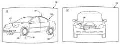
- FIG. 6is a different view of an image of the motor vehicle shown in FIG. 2 ;
- FIG. 7is a schematic illustration of a front view for the motor vehicle shown in FIG. 2 with a hood in an open position;
- FIG. 8is a schematic illustration of an image on the screen after an information tag associated with a battery has been activated
- FIG. 9is a front-left side view of a motor vehicle on a screen according to another embodiment of the present invention.
- FIG. 10is a schematic illustration of a sliding door in an open position after an information tag has been activated
- FIG. 11is a schematic diagram illustrating a processor and modules in communication with the screen according to an embodiment of the present invention.
- FIG. 12is a schematic diagram illustrating a list of possible images that can be provided by an image module according to an embodiment of the present invention.
- FIG. 13is a schematic diagram illustrating a list of possible information that can be provided by an information image module according to an embodiment of the present invention.
- FIG. 14is a schematic diagram illustrating a list of action items that can be executed by an actuator module according to an embodiment of the present invention.
- the present inventionprovides a virtual vehicle interface system for use in a motor vehicle. As such, the present invention has utility as a component for a motor vehicle.
- the virtual vehicle interface systemprovides a screen and an image of the motor vehicle that can be rotated on the screen such that a desired view of the vehicle can be observed by a driver, a passenger, and the like.
- One or more views of the vehicle on the screencan have an information tag that can be activated and result in information being provided to a user.
- the screencan be a touch screen and/or the information tag can be associated with and/or located proximate to a feature of the motor vehicle.
- the screencan be a “touchless” screen such as included with the “Remote Touch” haptic interface provided by Toyota Motor Corporation.
- Activation of the information tagcan be afforded by selecting the information tag using a remote control device and/or applying pressure to the touch screen, assuming naturally that the screen is a touch screen, at a location where the information tag is displayed. Once the information tag has been activated, a different view of the motor vehicle can be displayed on the screen and/or information on the feature that the tag is associated with can be displayed.
- the useruse the remote control device to rotate the image of the vehicle until a desired view with a desired feature is provided.
- the screenis a touch screen
- the usercan swipe the screen, i.e. use an object such as a finger to press and move along the screen, and rotate the image of the vehicle until a desired view with a desired feature is provided.
- a 360 degree view of the vehiclecan be provided with features associated therewith displayed on the screen.
- information tags associated with the various featurescan also be displayed on the screen.
- FIG. 1illustrates a portion of an interior 10 of a motor vehicle having a virtual vehicle interface system 100 .
- the interface system 100can have a screen 110 and one or more control knobs 150 .
- the one or more control knobs 150may or may not be used to provide an image of the motor vehicle on the screen 110 as shown in FIG. 1 .
- FIG. 2an enlarged view of the screen 110 shown in FIG. 1 is provided.
- the screen 110can have a screen region 112 that can display an image 120 of a motor vehicle.
- FIG. 2shows a front-left side view of the motor vehicle.
- the term left side and right sidecorrespond to the left and right of a driver seated in the motor vehicle.
- information tagsillustratively shown as a circle with an ‘i’ therein are shown generally at reference numerals 130 , 132 , 134 and 136 .
- the information tagscan be associated with and/or proximate to a feature of the motor vehicle.
- the information tag 130can be associated with a convertible top (not shown) of the motor vehicle, with activation of the tag 130 providing action items 131 and 133 which can be executed by pressing on the screen 110 at the desired location associated with the Open Top 131 action item or Close Top 133 action item if the screen is a touch screen.
- the Open Top 131 or Close Top 133 action itemcan be executed with a remote control device. It is appreciated that one of the action items may not be displayed depending on the current status of a motor vehicle feature. Stated differently, if the convertible top is in a closed position, activation of the information tag 130 could afford for only the action item 131 being displayed on the screen region 112 of the screen 110 .
- FIG. 4Another example of an information tag activation is shown in FIG. 4 .
- the information tag 134can be associated with a vehicle tire 124 with activation of the tag 134 affording an enlarged view of the vehicle tire 122 .
- information 135 regarding the tire 122can be displayed.
- the information 135can include a current tire air pressure for the tire 122 . In this manner, a user can check information on a feature of the motor vehicle.
- information tags 134 and 136are available for activation; however, information tags for vehicle tires on an opposite side of the vehicle are not accessible. However, information on features located on the opposite side of the vehicle can be obtained by rotating the image 120 on the screen region 112 , for example by swiping a finger or hand H in a first direction 1 on a touch screen, thereby rotating the image 120 as illustrated in FIGS. 5 and 6 . As shown in FIG. 6 , a rear-right side view of the vehicle 120 is shown along with information tags 138 , 140 and 142 . It is appreciated from FIG. 6 that information tag 138 can be associated with and is located proximate to the right rear tire of the vehicle. In addition, the information tag 140 is associated with the front right tire of the vehicle and information tag 142 is associated with the trunk lid.
- an information tagitself can provide information on a feature of the motor vehicle.
- information tag 144can be displayed only in the event that a light emitting device at this particular location, i.e. a rear tail light, rear brake light, etc., has stopped operating properly. In this manner, the display of an information tag such as tag 144 can alert a user that the light emitting device should be replaced.
- the information tag 144can operate in a similar fashion as tags 138 in that the tag 144 must be activated by a user before information of the light emitting device is displayed.
- FIG. 7a schematic illustration for the screen 110 after the information tag 132 shown in FIG. 2 has been activated is provided.
- a hood of the motor vehicle image 120is shown in an open position with an image of an engine area under the hood also provided.
- additional information tagsare shown under the hood, illustratively including information tags 146 and 148 .
- the information tag 146can be associated with a radiator for the motor vehicle
- the information tag 148can be associated with a battery for the motor vehicle.
- activation of the information tag 148can afford for an image of a battery for the motor vehicle being displayed on the screen 110 as shown in FIG. 8 with optional information 149 also provided.
- the information 149can include a current charge status for the battery 124 , and though not shown, activation of information tag 146 can provide information such as a temperature for cooling liquid in the radiator, a cooling liquid level, whether or not cooling liquid within the radiator should be changed, and the like.
- FIGS. 9 and 10another example of an image of a motor vehicle 200 is shown on the screen 110 .
- the image of the vehicle shown on the screen 110can correspond to the actual vehicle in which the virtual vehicle interface system is installed.
- the image 200corresponds to a van or minivan that contains a virtual vehicle interface system according to an embodiment of the present invention.
- the image 200can include a plurality of features such as tires, sliding doors, a hood, headlights, and the like.
- a plurality of information tagsillustratively shown as 210 , 220 , 230 and 240 can be displayed on the screen 110 .
- activation of a tag such as tag 240can afford for a different image to be provided on the screen 110 such as a sliding door being shown in an open position along with a view of at least a portion of an interior for the vehicle.
- an additional information tag 250can be shown and be associated with a seat 202 .
- Activation of the information tag 250can provide information associated with the seat 202 , illustratively including whether or not a seatbelt associated with the seat has been fastened, an action item that affords for the seat to be moved from a first position to a second position and the like.
- a usercan use the screen 110 of the virtual vehicle interface system 100 to perform operations such as opening a sliding door, closing a sliding door, moving a seat from a first position to a second position, checking an operation status of a light emitting device, checking the air pressure of one or more tires, checking liquid levels, opening a sun roof, opening a convertible top, closing the same, and the like.
- FIG. 11is a schematic diagram of a processor 160 having an image module 170 , an information module 180 and an actuator module 190 in communication with the screen 110 .
- the image module 170can have a plurality of images that can be displayed on the screen 110 , illustratively including a front view 171 , with an optional hood open 172 , a left side view 173 , with an optional door open 174 , and the like.
- the information module 180can have information on a plurality of motor vehicle features.
- FIG. 13illustrates the information module 180 operable to provide information on tire pressure 181 , battery charge 182 , oil level, 183 , oil pressure 184 , windshield wiper fluid level 185 , radiator fluid level 186 , turbo pressure 187 assuming the motor vehicle is turbo-charged, fuel or gas level 188 , current and/or average gas mileage 189 , maintenance information 189 ⁇ , etc.
- the actuator module 190can provide actuation or execution of one or more action items for the motor vehicle.
- FIG. 14illustrates the actuator module 190 operable to actuation or execution action items such as unlatch the hood 191 , open the trunk 192 , open the gas or fuel door 193 , open or close a sliding door 194 , open or close a convertible top 195 , open or close a sun roof 196 , lock or unlock one or more doors 197 , set rear door child locks 198 , set rear window locks 199 , fold or unfold one a rear seat 199 ⁇ , initiate a parking assist function 199 ⁇ , etc.
- the image module 170can display aspects of the information module 180 and/or actuator module 190 on the screen region 112 of the screen 110 .
- information provided by the information module 180 on one or more features of the motor vehiclecan be displayed on the screen region 112 via the image module 170 .
- information as to the current status and/or completed execution of one or more action itemscan be displayed on the screen region 112 via the image module 170 .
- the processor 160 , image module 170 , information module 180 and/or actuator module 190coordinate and/or operate with each other to provide desired images and/or information on the screen region 112 of the screen 110 .
- any type of screen and/or touch screen known to those skilled in the artcan be used with the virtual vehicle interface system of the present invention.
- images of the motor vehiclecan be actual photographic images, illustrative line drawings, illustrative CAD drawings, and the like.
- the inventionis not restricted to the illustrative examples and embodiments described above.
- the examples and embodimentsare not intended as limitations on the scope of the invention.
- Apparatus, systems, and the like described hereinare exemplary and not intended as limitations on the scope of the invention. Changes therein and other uses will occur to those skilled in the art. Accordingly, the scope of the invention is defined by the scope of the claims.
Landscapes
- Engineering & Computer Science (AREA)
- General Engineering & Computer Science (AREA)
- Theoretical Computer Science (AREA)
- Human Computer Interaction (AREA)
- Physics & Mathematics (AREA)
- General Physics & Mathematics (AREA)
- Instrument Panels (AREA)
- Superstructure Of Vehicle (AREA)
Abstract
Description
Claims (16)
Priority Applications (1)
| Application Number | Priority Date | Filing Date | Title |
|---|---|---|---|
| US12/778,564US8332093B2 (en) | 2010-05-12 | 2010-05-12 | Virtual vehicle interface |
Applications Claiming Priority (1)
| Application Number | Priority Date | Filing Date | Title |
|---|---|---|---|
| US12/778,564US8332093B2 (en) | 2010-05-12 | 2010-05-12 | Virtual vehicle interface |
Publications (2)
| Publication Number | Publication Date |
|---|---|
| US20110282537A1 US20110282537A1 (en) | 2011-11-17 |
| US8332093B2true US8332093B2 (en) | 2012-12-11 |
Family
ID=44912476
Family Applications (1)
| Application Number | Title | Priority Date | Filing Date |
|---|---|---|---|
| US12/778,564Expired - Fee RelatedUS8332093B2 (en) | 2010-05-12 | 2010-05-12 | Virtual vehicle interface |
Country Status (1)
| Country | Link |
|---|---|
| US (1) | US8332093B2 (en) |
Cited By (13)
| Publication number | Priority date | Publication date | Assignee | Title |
|---|---|---|---|---|
| US20140350752A1 (en)* | 2011-03-11 | 2014-11-27 | Intelligent Agricultural Solutions, Llc | Method and system for managing the hand-off between control terminals |
| US20150274016A1 (en)* | 2014-03-31 | 2015-10-01 | Fujitsu Ten Limited | Vehicle control apparatus |
| US9330062B2 (en) | 2011-03-11 | 2016-05-03 | Intelligent Agricultural Solutions, Llc | Vehicle control and gateway module |
| US9474208B2 (en) | 2011-11-15 | 2016-10-25 | Appareo Systems, Llc | System and method for determining material yield and/or loss from a harvesting machine using acoustic sensors |
| US9629308B2 (en) | 2011-03-11 | 2017-04-25 | Intelligent Agricultural Solutions, Llc | Harvesting machine capable of automatic adjustment |
| US9631964B2 (en) | 2011-03-11 | 2017-04-25 | Intelligent Agricultural Solutions, Llc | Acoustic material flow sensor |
| DE102015122602A1 (en) | 2015-12-22 | 2017-07-06 | Volkswagen Ag | Vehicle with an image acquisition unit and an operating system for operating devices of the vehicle and method for operating the operating system |
| US10085379B2 (en) | 2014-09-12 | 2018-10-02 | Appareo Systems, Llc | Grain quality sensor |
| US10249088B2 (en) | 2014-11-20 | 2019-04-02 | Honda Motor Co., Ltd. | System and method for remote virtual reality control of movable vehicle partitions |
| US10318138B2 (en) | 2011-03-11 | 2019-06-11 | Intelligent Agricultural Solutions Llc | Harvesting machine capable of automatic adjustment |
| US10321624B2 (en) | 2011-03-11 | 2019-06-18 | Intelligent Agriculture Solutions LLC | Air seeder manifold system |
| CN110239437A (en)* | 2019-05-08 | 2019-09-17 | 北京伏羲车联信息科技有限公司 | Vehicle-state rendering method and device |
| US11338681B2 (en)* | 2020-06-09 | 2022-05-24 | Hyundai Motor Company | Vehicle and information output method therefor |
Families Citing this family (23)
| Publication number | Priority date | Publication date | Assignee | Title |
|---|---|---|---|---|
| EP2581268B2 (en)* | 2011-10-13 | 2019-09-11 | Harman Becker Automotive Systems GmbH | Method of controlling an optical output device for displaying a vehicle surround view and vehicle surround view system |
| WO2013104378A1 (en)* | 2012-01-09 | 2013-07-18 | Audi Ag | Method and device for generating a 3d representation of a user interface in a vehicle |
| KR101916741B1 (en)* | 2012-01-25 | 2018-11-08 | 삼성전자 주식회사 | Operating Method for three-dimensional Handler And Portable Device supporting the same |
| US20130290899A1 (en)* | 2012-04-30 | 2013-10-31 | Asaf AMRAN | Obtaining status data |
| DE102012016774A1 (en)* | 2012-08-24 | 2014-02-27 | GM Global Technology Operations, LLC (n.d. Ges. d. Staates Delaware) | Device for the configuration of a motor vehicle |
| US20140095030A1 (en)* | 2012-09-28 | 2014-04-03 | Tesla Motors, Inc. | Sunroof Control Interface with Slide Control Functionality |
| US10180727B2 (en) | 2012-09-28 | 2019-01-15 | Tesla, Inc. | Method of launching an application and selecting the application target window |
| US20140095023A1 (en) | 2012-09-28 | 2014-04-03 | Tesla Motors, Inc. | Vehicle Air Suspension Control System |
| JP6018480B2 (en)* | 2012-11-05 | 2016-11-02 | 任天堂株式会社 | Information processing program, information processing apparatus, information processing system, and information processing method |
| US9244576B1 (en) | 2012-12-21 | 2016-01-26 | Cypress Semiconductor Corporation | User interface with child-lock feature |
| JP6621330B2 (en) | 2013-01-10 | 2019-12-18 | フォックス スポーツ プロダクションズ,エルエルシーFox Sports Productions, Llc | System, method and interface for viewer interaction for 3D display of vehicles |
| USD725137S1 (en) | 2013-03-08 | 2015-03-24 | Caterpillar Inc. | Display device with a graphical user interface |
| US9150147B2 (en) | 2013-03-08 | 2015-10-06 | Caterpillar Inc. | System and method for controlling features |
| JP2015186085A (en)* | 2014-03-25 | 2015-10-22 | 富士通テン株式会社 | Travel derivation apparatus and travel derivation method |
| DE102014009302B4 (en)* | 2014-06-26 | 2025-10-16 | Audi Ag | Method for operating virtual reality glasses and system with virtual reality glasses |
| US9886698B2 (en)* | 2014-07-25 | 2018-02-06 | Dreamwell, Ltd. | Augmented reality product brochure application |
| DE102016212034A1 (en)* | 2016-07-01 | 2018-01-04 | Robert Bosch Gmbh | Method for displaying a vehicle function |
| US10328896B2 (en)* | 2017-05-18 | 2019-06-25 | Ford Global Technologies, Llc | Vehicle theft avoidance systems and associated methods |
| US12282650B2 (en)* | 2019-10-18 | 2025-04-22 | Rockwell Collins, Inc. | Hypercontextual touch-the-plane (TTP) cabin management graphical user interface (GUI) |
| US12409809B2 (en)* | 2022-02-25 | 2025-09-09 | Honda Motor Co., Ltd. | Remote control of vehicle features based on tactile gestures on electronic device |
| CN115743303A (en)* | 2022-10-26 | 2023-03-07 | 北京集度科技有限公司 | Interaction method, device and storage medium based on three-dimensional vehicle model of vehicle |
| DE102023003205A1 (en)* | 2023-08-03 | 2025-02-06 | Mercedes-Benz Group AG | vehicle with a hood |
| CN118295750A (en)* | 2024-03-28 | 2024-07-05 | 小米汽车科技有限公司 | Display method, device, vehicle, medium and program product |
Citations (11)
| Publication number | Priority date | Publication date | Assignee | Title |
|---|---|---|---|---|
| JPH05112161A (en) | 1991-10-22 | 1993-05-07 | Honda Motor Co Ltd | Information display device for vehicle |
| US6131060A (en) | 1997-01-28 | 2000-10-10 | American Calcar Inc. | Method and system for adjusting settings of vehicle functions |
| US6275231B1 (en)* | 1997-08-01 | 2001-08-14 | American Calcar Inc. | Centralized control and management system for automobiles |
| US6493615B1 (en)* | 1999-08-09 | 2002-12-10 | Jeffrey Johnston | Vehicle diagnostic system |
| JP2005119465A (en) | 2003-10-16 | 2005-05-12 | Masahiro Ito | Vehicular display device by three-dimensional image |
| US7225413B1 (en) | 1997-11-25 | 2007-05-29 | Bayerische Motoren Werke Aktiengesellschaft | Device for controlling a display screen |
| US7292918B2 (en)* | 2002-06-21 | 2007-11-06 | Intel Corporation | PC-based automobile owner's manual, diagnostics, and auto care |
| US7330198B2 (en)* | 2003-02-26 | 2008-02-12 | Sony Corporation | Three-dimensional object manipulating apparatus, method and computer program |
| US20080249682A1 (en) | 2007-04-06 | 2008-10-09 | Visteon Global Technologies, Inc. | Touch control bezel for display devices |
| JP2009023471A (en) | 2007-07-19 | 2009-02-05 | Clarion Co Ltd | Vehicle information display device |
| US8239087B2 (en)* | 2008-02-14 | 2012-08-07 | Steering Solutions Ip Holding Corporation | Method of operating a vehicle accessory |
- 2010
- 2010-05-12USUS12/778,564patent/US8332093B2/ennot_activeExpired - Fee Related
Patent Citations (11)
| Publication number | Priority date | Publication date | Assignee | Title |
|---|---|---|---|---|
| JPH05112161A (en) | 1991-10-22 | 1993-05-07 | Honda Motor Co Ltd | Information display device for vehicle |
| US6131060A (en) | 1997-01-28 | 2000-10-10 | American Calcar Inc. | Method and system for adjusting settings of vehicle functions |
| US6275231B1 (en)* | 1997-08-01 | 2001-08-14 | American Calcar Inc. | Centralized control and management system for automobiles |
| US7225413B1 (en) | 1997-11-25 | 2007-05-29 | Bayerische Motoren Werke Aktiengesellschaft | Device for controlling a display screen |
| US6493615B1 (en)* | 1999-08-09 | 2002-12-10 | Jeffrey Johnston | Vehicle diagnostic system |
| US7292918B2 (en)* | 2002-06-21 | 2007-11-06 | Intel Corporation | PC-based automobile owner's manual, diagnostics, and auto care |
| US7330198B2 (en)* | 2003-02-26 | 2008-02-12 | Sony Corporation | Three-dimensional object manipulating apparatus, method and computer program |
| JP2005119465A (en) | 2003-10-16 | 2005-05-12 | Masahiro Ito | Vehicular display device by three-dimensional image |
| US20080249682A1 (en) | 2007-04-06 | 2008-10-09 | Visteon Global Technologies, Inc. | Touch control bezel for display devices |
| JP2009023471A (en) | 2007-07-19 | 2009-02-05 | Clarion Co Ltd | Vehicle information display device |
| US8239087B2 (en)* | 2008-02-14 | 2012-08-07 | Steering Solutions Ip Holding Corporation | Method of operating a vehicle accessory |
Cited By (17)
| Publication number | Priority date | Publication date | Assignee | Title |
|---|---|---|---|---|
| US9631964B2 (en) | 2011-03-11 | 2017-04-25 | Intelligent Agricultural Solutions, Llc | Acoustic material flow sensor |
| US20140350752A1 (en)* | 2011-03-11 | 2014-11-27 | Intelligent Agricultural Solutions, Llc | Method and system for managing the hand-off between control terminals |
| US10321624B2 (en) | 2011-03-11 | 2019-06-18 | Intelligent Agriculture Solutions LLC | Air seeder manifold system |
| US9324197B2 (en)* | 2011-03-11 | 2016-04-26 | Intelligent Agricultural Soultions | Method and system for managing the hand-off between control terminals |
| US9330062B2 (en) | 2011-03-11 | 2016-05-03 | Intelligent Agricultural Solutions, Llc | Vehicle control and gateway module |
| US10318138B2 (en) | 2011-03-11 | 2019-06-11 | Intelligent Agricultural Solutions Llc | Harvesting machine capable of automatic adjustment |
| US9629308B2 (en) | 2011-03-11 | 2017-04-25 | Intelligent Agricultural Solutions, Llc | Harvesting machine capable of automatic adjustment |
| US9474208B2 (en) | 2011-11-15 | 2016-10-25 | Appareo Systems, Llc | System and method for determining material yield and/or loss from a harvesting machine using acoustic sensors |
| US9346358B2 (en)* | 2014-03-31 | 2016-05-24 | Fujitsu Ten Limited | Vehicle control apparatus |
| US20150274016A1 (en)* | 2014-03-31 | 2015-10-01 | Fujitsu Ten Limited | Vehicle control apparatus |
| JP2015193280A (en)* | 2014-03-31 | 2015-11-05 | 富士通テン株式会社 | Vehicle control apparatus and vehicle control method |
| US10085379B2 (en) | 2014-09-12 | 2018-10-02 | Appareo Systems, Llc | Grain quality sensor |
| US10249088B2 (en) | 2014-11-20 | 2019-04-02 | Honda Motor Co., Ltd. | System and method for remote virtual reality control of movable vehicle partitions |
| DE102015122602A1 (en) | 2015-12-22 | 2017-07-06 | Volkswagen Ag | Vehicle with an image acquisition unit and an operating system for operating devices of the vehicle and method for operating the operating system |
| US11188211B2 (en) | 2015-12-22 | 2021-11-30 | Volkswagen Aktiengesellschaft | Transportation vehicle with an image capturing unit and an operating system for operating devices of the transportation vehicle and method for operating the operating system |
| CN110239437A (en)* | 2019-05-08 | 2019-09-17 | 北京伏羲车联信息科技有限公司 | Vehicle-state rendering method and device |
| US11338681B2 (en)* | 2020-06-09 | 2022-05-24 | Hyundai Motor Company | Vehicle and information output method therefor |
Also Published As
| Publication number | Publication date |
|---|---|
| US20110282537A1 (en) | 2011-11-17 |
Similar Documents
| Publication | Publication Date | Title |
|---|---|---|
| US8332093B2 (en) | Virtual vehicle interface | |
| DE102006000777B4 (en) | Virtual keyboard for vehicle access control | |
| US7826934B1 (en) | Theft and tamper resistant vehicle interior | |
| CN103260949B (en) | Display system for motor vehicles | |
| US20030231131A1 (en) | Remote control apparatus and method | |
| US10308167B2 (en) | Control of display for vehicle window | |
| EP2562052B1 (en) | Multifunctional trim strip for a motor vehicle | |
| CN110869235B (en) | Operating device for a motor vehicle | |
| US20180143754A1 (en) | Vehicle steering and control device (vscd) | |
| DE102016100064A1 (en) | Adative display in B-pillar | |
| US20120268665A1 (en) | Vehicle with Flexible Display | |
| US10005343B2 (en) | Methods and systems for controlling a sunroof shade | |
| CN104097607B (en) | Method for controlling central locking device of automobile | |
| US9752371B2 (en) | Method and system for controlling opening and closing vehicle door | |
| JP2005153684A (en) | On-vehicle equipment operating device | |
| DE102019207750A1 (en) | Method for programming an operating module for a vehicle and a corresponding operating module | |
| CN110949401A (en) | Vehicle control system and method | |
| DE102014010663A1 (en) | Display system for a motor vehicle | |
| US10059257B2 (en) | Rear trunk button localization for end user | |
| US20100070143A1 (en) | Vehicles Including Master Control Device For Control Of Power Door | |
| US20240200375A1 (en) | Vehicle quarter-panel window assembly | |
| US20170050522A1 (en) | Universal combination meters | |
| CN103541612B (en) | The method of the car door of closing or open on body of a motor car or trunk lid etc. | |
| DE202021002012U1 (en) | Steering wheel with a touchscreen control element for motor vehicles or e-cars, e-cars, trucks, electric trucks or construction machines | |
| US20250244646A1 (en) | Vehicular projection display at window of vehicle |
Legal Events
| Date | Code | Title | Description |
|---|---|---|---|
| AS | Assignment | Owner name:TOYOTA MOTOR ENGINEERING & MANUFACTURING NORTH AME Free format text:ASSIGNMENT OF ASSIGNORS INTEREST;ASSIGNORS:YAMASAKI, BRYAN ELSE;PIERFELICE, JEFFREY EDWARD;REEL/FRAME:024374/0631 Effective date:20100510 | |
| FEPP | Fee payment procedure | Free format text:PAYOR NUMBER ASSIGNED (ORIGINAL EVENT CODE: ASPN); ENTITY STATUS OF PATENT OWNER: LARGE ENTITY | |
| STCF | Information on status: patent grant | Free format text:PATENTED CASE | |
| AS | Assignment | Owner name:TOYOTA MOTOR CORPORATION, JAPAN Free format text:ASSIGNMENT OF ASSIGNORS INTEREST;ASSIGNOR:TOYOTA MOTOR ENGINEERING & MANUFACTURING NORTH AMERICA, INC.;REEL/FRAME:029526/0941 Effective date:20121214 | |
| CC | Certificate of correction | ||
| FPAY | Fee payment | Year of fee payment:4 | |
| FEPP | Fee payment procedure | Free format text:MAINTENANCE FEE REMINDER MAILED (ORIGINAL EVENT CODE: REM.); ENTITY STATUS OF PATENT OWNER: LARGE ENTITY | |
| LAPS | Lapse for failure to pay maintenance fees | Free format text:PATENT EXPIRED FOR FAILURE TO PAY MAINTENANCE FEES (ORIGINAL EVENT CODE: EXP.); ENTITY STATUS OF PATENT OWNER: LARGE ENTITY | |
| STCH | Information on status: patent discontinuation | Free format text:PATENT EXPIRED DUE TO NONPAYMENT OF MAINTENANCE FEES UNDER 37 CFR 1.362 | |
| FP | Lapsed due to failure to pay maintenance fee | Effective date:20201211 |