US8331335B2 - Location aware background access point scanning for WLAN - Google Patents
Location aware background access point scanning for WLANDownload PDFInfo
- Publication number
- US8331335B2 US8331335B2US12/252,965US25296508AUS8331335B2US 8331335 B2US8331335 B2US 8331335B2US 25296508 AUS25296508 AUS 25296508AUS 8331335 B2US8331335 B2US 8331335B2
- Authority
- US
- United States
- Prior art keywords
- wlan
- communication device
- wlan access
- access points
- access point
- Prior art date
- Legal status (The legal status is an assumption and is not a legal conclusion. Google has not performed a legal analysis and makes no representation as to the accuracy of the status listed.)
- Active, expires
Links
Images


Classifications
- H—ELECTRICITY
- H04—ELECTRIC COMMUNICATION TECHNIQUE
- H04W—WIRELESS COMMUNICATION NETWORKS
- H04W48/00—Access restriction; Network selection; Access point selection
- H04W48/20—Selecting an access point
- H—ELECTRICITY
- H04—ELECTRIC COMMUNICATION TECHNIQUE
- H04W—WIRELESS COMMUNICATION NETWORKS
- H04W4/00—Services specially adapted for wireless communication networks; Facilities therefor
- H04W4/02—Services making use of location information
- H04W4/029—Location-based management or tracking services
- H—ELECTRICITY
- H04—ELECTRIC COMMUNICATION TECHNIQUE
- H04W—WIRELESS COMMUNICATION NETWORKS
- H04W4/00—Services specially adapted for wireless communication networks; Facilities therefor
- H04W4/02—Services making use of location information
- H—ELECTRICITY
- H04—ELECTRIC COMMUNICATION TECHNIQUE
- H04W—WIRELESS COMMUNICATION NETWORKS
- H04W84/00—Network topologies
- H04W84/02—Hierarchically pre-organised networks, e.g. paging networks, cellular networks, WLAN [Wireless Local Area Network] or WLL [Wireless Local Loop]
- H04W84/10—Small scale networks; Flat hierarchical networks
- H04W84/12—WLAN [Wireless Local Area Networks]
Definitions
- the present disclosurerelates generally to communication systems, and more particularly, to wireless communication systems that employ position information to enhance the performance of wireless data communication.
- WLANwireless local area network
- Communication devicesmay connect with a WLAN upon detection of an access point.
- the communication devicemay actively or passively search for access points having signals that have an acceptable quality, such as having a received signal strength indicator (RSSI) that is above a threshold.
- RSSIreceived signal strength indicator
- a communication device that falls out of the range of an associated access pointmay attempt to connect with one or more other access points, if available.
- WLAN coveragemay be spotty with a mobile device such as a mobile phone, a PDA, etc., and thus mobile communication devices may be continually searching for additional access points with which to connect.
- a communication devicesuch as a mobile phone operating in a long range mobile phone network, such as global system for mobile communication (GSM), may continually perform a background scan for WLAN access points, looking for access points having acceptable RSSI levels.
- GSMglobal system for mobile communication
- RSSIis generally a measurement of the power of a received signal.
- communication devices with WLAN capabilitiesselect access points based on RSSI. For instance, a communication device whose RSSI drops below a certain threshold may seek to connect to another access point with an RSSI above the threshold, if available.
- a communication devicemay scan a wireless communication network that is compliant with the Institute for Electrical and Electronics (IEEE) 802.11 Standard handoff algorithm for available access points using one of two known channel scanning methods, passive scanning and active scanning.
- IEEE 802.11 Standard handoff algorithmincludes a communication device 102 and a plurality of access points 104 - 114 , each at potentially different distances from the communication device 102 .
- Each access point 104 - 114(or at least access points in close proximity or with overlapping coverage areas) may be operating on a different communication channel.
- each access pointperiodically may transmit a signal often referred to as a beacon to let other communication devices know of its presence.
- the beaconwill include various information including a channel number to indicate which channel it is using.
- the communication device 102may switch to each of a plurality of potentially available channels and listen for a beacon. For each channel, if a beacon is received and an RSSI is above a threshold, the channel/access point may be noted as available. After scanning all the channels, the communication device 102 may choose one of the available access points (if there is more than one) and attempt to associate with the chosen access point. For example, the communication device 102 may choose the access point with the highest RSSI.
- a communication device with WLAN capabilitiesWhen a communication device with WLAN capabilities powers up in an already existing wireless network, it may utilize passive scanning to find available wireless access points and determine with which access point to associate. Passive scanning may also be used when the device is already associated with an access point. For example, if the communication device 102 is a mobile device, it may continuously perform passive scanning in case the connection with the current access point is suddenly lost or degrades. Additionally, if the RSSI for an access point with which the communication device 102 is associated has fallen below a threshold (for example, because the communication device 102 has moved further away from the associated access point), the communication device 102 may utilize passive scanning to find another access point with which to associate.
- a thresholdfor example, because the communication device 102 has moved further away from the associated access point
- the device 102may listen for beacons for approximately 100 ms at each channel, for instance. Thus, the device 102 may spend 1.4 seconds (100 ms/channel ⁇ 14 channels) scanning for beacons.
- the communication device 102may maintain a list of access points in range of the device 102 .
- the communication device 102may transmit a probe request signal on each of the channels associated with the access points on the list, except for the access point with which it is currently associated. After transmitting a probe request signal, the communication device 102 may wait a period of time for a response from the corresponding access point. The response may indicate the RSSI of the channel and/or the channel load.
- the device 102may seek to disconnect from the current access point and connect to an access point with a higher RSSI or a better combination of RSSI and channel load, for example.
- a methodincludes determining respective distances between a communication device and a plurality of wireless local area network (WLAN) access points, and selecting one of the plurality of WLAN access points with which the communication device is to associate based on the determined distances.
- WLANwireless local area network
- an apparatuscomprises a wireless local area network (WLAN) channel scanning control unit configured to determine respective distances between a communication device and a plurality of WLAN access points, and select one of the plurality of WLAN access points with which the communication device is to associate based on the determined distances.
- WLANwireless local area network
- a methodincludes comparing a velocity of a communication device to a threshold, and disabling a wireless local area network (WLAN) access point scanning process based on comparing the velocity to the threshold.
- WLANwireless local area network
- an apparatuscomprises a wireless local area network (WLAN) channel scanning control unit configured to compare a velocity of a communication device to a threshold, and disable a WLAN access point scanning process based on comparing the velocity to the threshold.
- WLANwireless local area network
- FIG. 1is a block diagram of an implementation of a wireless local area network
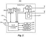
- FIG. 2is a block diagram of a mobile phone that may utilize location awareness techniques such as described herein;
- FIG. 3is a flow diagram of an example method for implementing a sleep mode for a communication device based on velocity.
- FIG. 4is a flow diagram of an example method for testing conditions in which a background scan on a set of neighboring channels may occur.
- FIG. 5is a flow diagram of an example method for a communication device which may be aware of the location of the neighboring access points may perform a background scan.
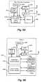
- FIG. 6Ais a block diagram of a high definition television that may utilize location awareness techniques such as described herein;
- FIG. 6Bis a block diagram of a vehicle that may utilize location awareness techniques such as described herein;
- FIG. 6Cis a block diagram of a set top box that may utilize location awareness techniques such as described herein;
- FIG. 6Dis a block diagram of a media player that may utilize location awareness techniques such as described herein;
- FIG. 6Eis a block diagram of a voice over IP device that may utilize location awareness techniques such as described herein,
- GPSglobal positioning system
- FIG. 2is a block diagram of an example mobile phone 250 that includes both a WLAN interface 252 , having a WLAN channel scanning control unit 253 , and a GPS receiver 254 .
- the mobile device 250also may include a cellular antenna 256 , signal processing and/or control circuits, which are generally identified in FIG. 2 at 258 , a mass data storage 264 , and/or a memory 266 .
- the mobile phone 250includes a microphone 268 , an audio output 270 such as a speaker and/or audio output jack, a display 272 and/or an input device 274 such as a keypad, pointing device, touch pad, voice actuation and/or other input device.
- the input device 274may include a touch screen associated with the display 272 .
- Signal processing and/or control circuits 258 and/or other circuits (not shown) in mobile phone 250may process data, perform coding and/or encryption, perform calculations, format data and/or perform other mobile phone functions.
- Mobile phone 250may communicate with mass data storage 264 that stores data in a nonvolatile manner such as optical and/or magnetic storage devices for example hard disk drives HDD and/or DVDs.
- Mobile phone 250may include a memory 266 such as RAM, ROM, low latency nonvolatile memory such as flash memory and/or other suitable electronic data storage.
- the UPS receiver 254may generate location information indicative of a location of the mobile phone 250 . As will be described in more detail below, the location information may be utilized to enhance the performance of the WLAN interface 252 .
- the WLAN interface 252enables the mobile phone 250 to communicate via a WLAN. For example, it may be preferable to utilize a WLAN for voice or data communications as compared to utilizing wide-area cellular network when out of range of the cellular network but in range of the WLAN, when communication via the WLAN may be less expensive than communication via the cellular network, etc.
- a communication device with a positioning systemsuch as the mobile phone 250 may also be aware of its velocity.
- the position informationmay be analyzed over time to generate velocity information.
- the GPS receiver 254may generate velocity information.
- some other componentsuch as the WLAN interface 252 or the signal processing/control block 258 may generate velocity information based on the position information generated by the GPS receiver 254 .
- the position information and/or the velocity informationmay be utilized to enhance the power efficiency of the WLAN interface 252 , for example. For instance, if the mobile phone 250 is traveling at-high speeds (e.g., in an automobile), the WLAN interface 252 might continuously scan for WLAN access points because the mobile phone 250 may be quickly entering and leaving the coverage areas of access points. In such a scenario, WLAN communication cannot occur effectively. Yet, the continuous scanning process may consume power, which may be a limited resource if the mobile phone 205 is operating on battery power, for example. But if the mobile phone 250 is aware of its velocity, the WLAN scanning process could be disabled, thereby reducing power consumption.
- the WLAN scanning control unit 253may receive position information and/or velocity information, such as from the GPS receiver 254 .
- the WLAN scanning control unit 253may be configured to control WLAN scanning based on the position information and/or velocity information.
- the WLAN scanning control unit 253is illustrated in FIG. 2 as being a component of the WLAN interface 252 , the WLAN scanning control unit 253 can be implemented in other components of the mobile phone 250 , such as in the signal processing and/or control circuits 258 .
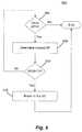
- FIG. 3is a flow diagram of an example scanning method 300 that utilizes velocity information and position information.
- the method 300may be implemented by a communication device such as the example mobile phone 250 of FIG. 2 .
- the method 300will be described with reference to FIG. 2 .
- the method 300may be implemented by a communication device different than the mobile phone 250 , and the mobile phone 250 may utilize a different scanning method that utilizes velocity and/or position information.
- the method 300may be utilized when a mobile device is not currently associated with an access point, for example.
- a positioning systemsuch as the GPS receiver 254 may report position and velocity information.
- the GPS receiver 254may send the position information and the velocity information to the WLAN scanning control unit 253 .
- the positioning systemmay merely report the position information.
- the velocity informationmay be generated (by the WLAN scanning control unit 253 , for example) based on position information generated over time by the positioning system.
- itmay be determined if the velocity is above a threshold T 1 . Because an access point may have a limited range, threshold T 1 may be set to a velocity at which the RSSI of an access point will not quickly diminish, relatively speaking.
- threshold T 1may be set at 2 m/s, the speed at which a person would typically walk. At this velocity, the communication device can be expected to stay within range of the access point for some amount of time that would permit effective, practical, and/or acceptable WLAN communication. But at a higher speed, such as 8 m/s, WLAN communication may become ineffective because the communication device would be expected to stay within range of any one access point for only a short amount of time. Thus, data communications may become unacceptably slow and/or intermittent because too much time is spent attempting to associate with and disassociating with different access points, scanning for new access points, etc., or the device intermittently and/or for unacceptably long periods goes out of range of any access point.
- the threshold T 1may be set to a variety of other speeds besides 2 m/s, and different thresholds may be utilized for different implementations.
- the WLAN scanning control unit 253may determine if the velocity is above a threshold T 1 . If the velocity is above the threshold T 1 , the WLAN interface 252 may be put in a sleep mode or at least the scanning process may be disabled at a block 306 .
- the WLAN scanning control unit 253may cause the WLAN interface 252 to go into the sleep mode or at least cause the scanning process may be disabled. In this mode, the mobile phone 250 may conserve power that it may otherwise be inefficiently using by continuously scanning for access points that may quickly fall out of range or with which it may even not be able to associate.
- the mobile phonemay scan for available access points, such as by using a passive scanning technique.
- the WLAN scanning control unit 253may enable or cause the WLAN interface 252 to scan for available access points.
- Each of at least some access pointsmay be aware of its location, and this access point location information may be transmitted to the mobile phone 250 during the scanning block 308 . Additionally, the mobile phone 250 also may be able to determine the RSSI associated with each access point. Thus, after the block 308 , the device 250 may be aware of the RSSI associated with each of one or more access points and position information for possibly one or some or all (or possibly none) of the access points.
- respective distances between the mobile device and each of the access pointsmay be calculated using the position information generated by the GPS receiver 254 .
- the WLAN scanning control unit 253may calculate the distance information.
- distance informationmay be determined using any of a variety of techniques and may vary depending upon the format of the position information.
- an access point with which to associateis determined based on the distances calculated at the block 310 . Determining the access point with which to connect may be based on other information as well such as RSSI information, channel load information (such as channel load indicators), etc. In one particular implementation, the nearest access point in which the RSSI is above a threshold T 2 may be chosen. The threshold T 2 may be at a level corresponding to a sufficient RSSI power level. The threshold T 2 may be chosen depending on the particular implementation.
- the WLAN scanning control unit 253may determine or select the access point. Selecting an access point based on location may provide an advantage over typical passive and active scanning techniques, on average. For example, if the closest access point is chosen, the mobile device may be expected, on average, to stay within its coverage area for a longer time as compared to choosing an access point that is farther away. Of course choosing the closest access point may not always result in staying in a coverage area for the longest time. For example, if the mobile phone is moving away from the closest access point, the mobile phone may stay within the coverage area of another access point which the mobile phone is moving towards. Thus, optional implementations may include determining direction information, and determining an access point with which to associate may be further based on the direction information.
- the direction informationmay indicate a direction in which the mobile device is traveling, and the direction information may be generated by the positioning system (e.g., GPS receiver 254 ), the WLAN interface or some other component such as the signal processing/control block 258 .
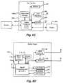
- FIG. 4is a flow diagram of an example method 400 for determining, based on position information, whether to initiate background scanning when a mobile device is already associated with an access point.
- the method 400may be implemented by a communication device such as the example mobile phone 250 of FIG. 2 .
- the method 400will be described with reference to FIG. 2 .
- the method 400may be implemented by a communication device different than the mobile phone 250 , and the mobile phone 250 may implement methods other than the method 400 .
- the mobile devicemay send a neighbor information request to an access point with which it is currently associated (the “current access point”).
- the neighbor information requestmay be a request for information about access point neighbors of the current access point, such as the channels on which each neighbor is operating, the location of each neighbor, etc.
- the request for information sent by the mobile devicemay be a neighbor request frame specified in the IEEE 802.11k Standard, for example.
- the WLAN scanning control unit 253may cause the request to be sent via a WLAN link with the current access point.
- the current access pointmay respond to the request (block 402 ) by, for example, sending information to the mobile device regarding neighboring access points, such as the position of each neighboring access point, the channel on which each neighboring access point is operating, channel load information for each neighboring access point, etc.
- the WLAN interface 252may receive the response via the WLAN link with the current access point.
- respective distances between the mobile device and the neighboring access pointsmay be calculated.
- the WLAN scanning control unit 253may calculate the distances.
- Table 1is an example list of neighboring access points arranged in order of increasing distance from the mobile phone 250 . In this example, positions an x, y, z coordinate format, but any other suitable position information format may be used. In Table 1, it is assumed for simplicity that the mobile phone 250 is located at coordinates (0,0,0). In reality, however, the mobile phone 250 will typically not be located at position (0,0,0). Table 1 also lists the channel via which each access point communicates. Information such as the information of Table 1 may be obtained based on execution of the blocks 404 and 406 .
- Such informationmay be stored in a memory.
- the informationmay be stored in a memory coupled to or included in the WLAN scanning control unit 253 , for example.
- the informationcould be organized in any of a variety of formats to facilitate ease of ranking or sorting based on one or more parameters such as distance, channel load, etc.
- the information regarding access pointscould be ordered based on the distance information, such as in Table 1.
- the WLAN scanning control unit 253may calculate the distance information and cause the distance information to be stored.
- Blocks 408 , 412 , and 414represent conditions that a mobile device may check to decide whether to perform a background scan.
- the order in which each of the three conditions 408 , 412 , and 414 are checkedmay vary. Generally, as long as at least one of the three conditions 408 , 412 , and 414 is met, a background scan may be performed.
- the WLAN scanning control unit 253may check the three conditions.
- Threshold T 3may be, for example, a minimum requirement corresponding to an RSSI level sufficient to sustain a connection.
- the threshold T 3may be the same as the threshold T 2 .
- the threshold T 3may be different than the threshold T 2 , such as higher or lower than the threshold T 2 .
- the WLAN scanning control unit 253may determine if the RSSI of the current access point is less than the threshold T 3 .
- the mobile phone 250may initiate a background scan on a set of channels corresponding to the neighboring access points determined based on the information received at the block 404 .
- the block 410may be implemented using a variety of techniques, including known techniques.
- the block 410may be implemented using a conventional active scanning technique.
- the block 410may be implemented using a background scanning technique utilizing position information. An example method for background scanning technique utilizing position information will be described below with reference to FIG. 5 .
- the WLAN scanning control unit 253may cause the background scanning process to be initiated.
- the WLAN interface 252may implement the background scanning process.
- the flowmay proceed to a block 412 , at which it may be determined if a distance, D 1 , between the mobile device and the current access point is greater then a threshold T 4 .
- the threshold T 4may be set using a variety of techniques. For example, the threshold T 4 may be set to a distance beyond which it is estimated that the RSSI may begin to quickly degrade below an acceptable level. If the distance D 1 is greater than threshold T 4 , then the flow may proceed to the block 410 .
- the flowmay proceed to the block 414 , at which it may be determined if the distance D 1 is greater than a distance D 2 .
- the distance D 2may be a distance between the mobile device and a nearest neighboring access point (other than the current access point). If the distance D 2 is less than the distance D 1 then the flow may proceed to the block 410 .
- Checking the conditions corresponding to the blocks 408 , 412 , 414optionally may be repeated some number of times, for some time period, until some event occurs, etc. For example, checking the conditions corresponding to the blocks 408 , 412 , 414 may be repeated until it is determined that the method 400 should be restarted. Checking the conditions corresponding to the blocks 408 , 412 , 414 may be implemented by the WLAN scanning control unit 253 , for example.
- checking the conditions corresponding to the blocks 408 , 412 , 414may not be performed when it is determined that a velocity of the mobile device is above a velocity threshold, such as the velocity threshold discussed with respect to FIG. 3 .
- FIG. 5is a flow diagram of an example background scanning method 500 that utilizes position information.
- the method 500may be implemented by a communication device such as the example mobile phone 250 of FIG. 2 .
- the method 500will be described with reference to FIG. 2 .
- the method 500may be implemented by a communication device different than the mobile phone 250 , and the mobile phone 250 may implement methods other than the method 500 .
- the method 500may be implemented by a mobile device when the mobile device is currently associated with an access point (the current access point). If the method 400 is implemented by the mobile device, the block 410 may include the method 500 .
- the method 500may begin at a block 504 , at which it may be determined if there are other neighboring access points (besides the current access point) with which the mobile device might be able to associate. Determining if there are other neighboring access points may be implemented based on information obtained from previously performed scanning procedures such as a passive scan or an active scan. In one implementation, determining if there are other neighboring access points may be implemented based on information obtained from a procedure such as described with respect to blocks 402 and 404 of FIG. 4 .
- determining if there are other neighboring access pointsmay be implemented based on information obtained in response to a neighbor request frame. If there are no other access points with which the mobile device might be able to associate, the method 500 may end.
- the flowmay proceed to a block 508 .
- the closest other access pointmay be determined.
- the block 508may be implemented based on distance information for the one or more other access points (i.e., respective distances between the mobile device and each of the other access points) calculated according to a method such as described with respect to the block 406 of FIG. 4 , for instance.
- Distance information for the one or more other access pointsmay have been previously calculated and stored in a memory, and this information may be analyzed to determine the closest other access point. For example, access points could be ranked or ordered according to their distance from the mobile device, and the closest access point could be determined based on the order or ranking.
- distance information for the other access pointscould be compared to determine the closest access points.
- the flowmay proceed to the block 516 , at which the mobile device may attempt to roam to the access point that was determined at the block 508 .
- the flowmay proceed back to the block 504 .
- the access point previously determined at the block 508may be removed from consideration in terms of implementing the next round of the blocks 504 , 508 , 512 . In this way, the next closest access point will next be considered.
- the blocks 504 , 508 , 512may be repeated, evaluating the next closest access point each time, until there are no more other access points to consider or until an access point with an RSSI greater than T 5 is found.
- a velocity of the mobile devicemay be greater than a velocity threshold (such as the threshold T 1 discussed with respect to FIG. 3 .
- a velocity thresholdsuch as the threshold T 1 discussed with respect to FIG. 3 .
- the method 500may be not started, terminated if already started, etc.
- the method 500analyzes other access points in an order, wherein the order is based on the distance of the other access points to the mobile device.
- the other access pointsare analyzed in the order to determine an access point to which to roam.
- the method 500may find another access point having an acceptable RSSI more quickly than other methods that do not utilize position information.
- the ordermay be based on other information in addition to the position information, such as RSSI, channel load, etc.
- each of the blocks 504 , 508 , 512 , 516may be implemented by the WLAN scanning control unit 253 , for example.
- the WLAN scanning control unit 253could implement the method 500 based on information from the WLAN interface 252 and by sending control information to the WLAN interface 252 , such as a signal instructing the WLAN interface 252 to attempt to roam to a particular access point.
- the WLAN scanning control unit 253could implement the method 500 based on information from other components of the WLAN interface 252 and by sending control information to other components of the WLAN interface 252 , such as a signal instructing the WLAN interface 252 to attempt to roam to a particular access point. More generally, the WLAN scanning control unit 253 may analyze other access points in an order, wherein the order is based on the distance of the other access points to the mobile device, to determine an access point to which the WLAN interface 252 should attempt to roam.
- one or more of the methods 300 , 400 , and 500 , or portions of these methods (or similar methods)may be implemented by a WLAN channel scanning control unit, which in turn may be implemented in hardware, firmware, software, or any combination of hardware, firmware, and/or software.
- the WLAN channel scanning control unitmay be a component of a WLAN interface, for example.
- the WLAN channel scanning control unitmay be a component of another subsystem of a communication device, such as a control block separate from the WLAN interface.
- the WLAN channel scanning control unitmay be coupled to the WLAN interface.
- the example mobile phone 250was described as including a GPS receiver 254 , it will be understood that other positioning systems may also be utilized such as other satellite-based positioning systems. Also, non-satellite-based positioning systems may also be utilized. For example, if the mobile device is a mobile phone, a positioning system could determine position information based on signals received from multiple cellular phone base stations, or based on signals received from multiple WLAN access points. A positioning system may utilize a triangulation type method, for example, to determine a position of the mobile phone 250 based on the signals received from the multiple base stations or access points. Also, the positioning system could be located outside of the mobile phone 250 .
- a positioning system in a cellular phone base station or a WLAN access pointcould determine position information based on signals received from the mobile phone 250 at multiple cellular phone base stations or at multiple WLAN access points.
- a positioning systemmay utilize a triangulation type method, for example, to determine a position of the mobile phone 250 based on the signals received at the multiple base stations or access points.
- the positioning systemcould then transmit the determined position information to the mobile phone 250 via a cellular phone link or a WLAN link.
- FIGS. 6A-6Eillustrate various devices in which WLAN scanning techniques such as described above may be employed.
- HDTV 620includes a mass data storage 627 , an HDTV signal processing and control block 622 , a memory 628 , a WLAN interface 629 and a GPS receiver 600 .
- HDTV 620receives HDTV input signals in either a wired or wireless format and generates HDTV output signals for a display 626 .
- signal processing circuit and/or control circuit 622 and/or other circuits (not shown) of HDTV 620may process data, perform coding and/or encryption, perform calculations, format data and/or perform any other type of HDTV processing that may be required.
- HDTV 620may communicate with a mass data storage 627 that stores data in a nonvolatile manner such as optical and/or magnetic storage devices.
- the mass storage devicemay be a mini HDD that includes one or more platters.
- HDTV 620may be connected to memory 628 such as RAM, ROM, low latency nonvolatile memory such as flash memory and/or other suitable electronic data storage.
- HDTV 620also may support connections with a WLAN via WLAN interface 629 .
- One or more of the signal processing/control block 622 , the WLAN interface 629 , and the GPS receiver 600may implement channel scanning techniques such as described above.
- a WLAN scanning control unit(not shown) in one or more of the signal processing/control block 622 , the WLAN interface 629 , and the GPS receiver 600 may implement channel scanning techniques such as described above.
- the vehicle 630includes a control system that may include mass data storage 646 , a WLAN interface 648 , and a GPS receiver 650 .
- a powertrain control system 632may receive inputs from one or more sensors 636 such as temperature sensors, pressure sensors, rotational sensors, airflow sensors and/or any other suitable sensors and generate one or more output control signals 638 such as engine operating parameters, transmission operating parameters, and/or other control signals.
- Control system 640may likewise receive signals from input sensors 642 and/or output control signals to one or more output devices 644 .
- control system 640may be part of an anti-lock braking system (ABS), a navigation system, a telematics system, a vehicle telematics system, a lane departure system, an adaptive cruise control system, a vehicle entertainment system such as a stereo, DVD, compact disc and the like.
- ABSanti-lock braking system
- the WLAN interface 648 and the GPS receiver 650may be coupled to the control system 640 .
- Control system 640also may support connections with a WLAN via the WLAN interface 648 .
- the WLAN interface 648may be used when the vehicle is within access of one or more network access points.
- Powertrain control system 632may communicate with mass data storage 627 that stores data in a nonvolatile manner such as optical and/or magnetic storage devices. Powertrain control system 632 may be connected to memory 647 such as RAM, ROM, low latency nonvolatile memory such as flash memory and/or other suitable electronic data storage. Powertrain control system 632 also may support connections with a WLAN (not depicted) via a WLAN interface 648 . One or more of the powertrain control system 632 , the control system 640 , the WLAN interface 648 , and the GPS receiver 650 may implement channel scanning techniques such as described above. For example, a WLAN scanning control unit (not shown) in one or more of the powertrain control system 632 , the control system 640 , the WLAN interface 648 , and the GPS receiver 650 may implement channel scanning techniques such as described above.
- a set top box 680may include signal processing and/or control circuits, which are generally identified in FIG. 6C at 684 , and mass data storage 690 .
- Set top box 680also may include a WLAN interface 696 and a GPS receiver 698 .
- Set top box 680receives signals from a source such as a broadband source and outputs standard and/or high definition audio/video signals suitable for a display 688 such as a television and/or monitor and/or other video and/or audio output devices.
- Signal processing and/or control circuits 684 and/or other circuits (not shown) of the set top box 680may process data, perform coding and/or encryption, perform calculations, format data and/or perform any other set top box function.
- Set top box 680may include mass data storage 690 that stores data in a nonvolatile manner. Mass data storage 690 may include optical and/or magnetic storage devices for example hard disk drives HDD and/or DVDs. Set top box 680 may include memory 694 such as RAM, ROM, low latency nonvolatile memory such as flash memory and/or other suitable electronic data storage. Set top box 680 also may support connections with a WLAN via WLAN interface 696 . One or more of the signal processing/control block 684 , the WLAN interface 696 , and the GPS receiver 698 may implement channel scanning techniques such as described above. For example, a WLAN scanning control unit (not shown) in one or more of the signal processing/control block 684 , the WLAN interface 696 , and the GPS receiver 698 may implement channel scanning techniques such as described above.
- a media player 700may include either or both signal processing and/or control circuits, which are generally identified in FIG. 6D at 704 , and/or mass data storage 710 .
- media player 700includes a display 707 and/or a user input 708 such as a keypad, touchpad and the like.
- media player 700may employ a graphical user interface (GUI) that typically employs menus, drop down menus, icons and/or a point-and-click interface via display 707 and/or user input 708 .
- Media player 700further includes an audio output 709 such as a speaker and/or audio output jack.
- Signal processing and/or control circuits 704 and/or other circuits (not shown) of media player 700may process data, perform coding and/or encryption, perform calculations, format data and/or perform any other media player function.
- Media player 700may communicate with mass data storage 710 that stores data such as compressed audio and/or video content in a nonvolatile manner and may utilize jitter measurement.
- the compressed audio filesinclude files that are compliant with MP3 format or other suitable compressed audio and/or video formats.
- the mass data storagemay include optical and/or magnetic storage devices for example hard disk drives HDD and/or DVDs.
- Media player 700may include memory 714 such as RAM, ROM, low latency nonvolatile memory such as flash memory and/or other suitable electronic data storage.
- Media player 700also may support connections with a WLAN via a WLAN interface 716 .
- Media player 700also may include a GPS receiver 718 . Communication via the WLAN interface 716 may be used to support real-time updates, downloading content, streaming of media content, etc.
- One or more of the signal processing/control block 704 , the WLAN interface 716 , and the GPS receiver 718may implement channel scanning techniques such as described above.
- a WLAN scanning control unit(not shown) in one or more of the signal processing/control block 704 , the WLAN interface 716 , and the GPS receiver 718 may implement channel scanning techniques such as described above.
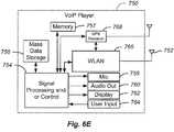
- VoIP phone 750may include an antenna 752 .
- the VoIP phone 750may include either or both signal processing and/or control circuits, which are generally identified in FIG. 6E at 754 , and mass data storage of the VoIP phone 750 .
- VoIP phone 750includes, in part, a microphone 758 , an audio output 760 such as a speaker and/or audio output jack, a display monitor 762 , an input device 764 such as a keypad, pointing device, voice actuation and/or other input devices.
- VoIP phone 750also may include a WLAN interface 766 and a GPS receiver 718 .
- Signal processing and/or control circuits 754 and/or other circuits (not shown) in VoIP phone 750may process data, perform coding and/or encryption, perform calculations, format data and/or perform other VoIP phone functions.
- One or more of the signal processing/control block 754 , the WLAN interface 766 , and the GPS receiver 768may implement channel scanning techniques such as described above.
- a WLAN scanning control unit (not shown) in one or more of the signal processing/control block 754 , the WLAN interface 766 , and the GPS receiver 768may implement channel scanning techniques such as described above.
- VoIP phone 750may communicate with mass data storage 756 that stores data in a nonvolatile manner such as optical and/or magnetic storage devices, for example hard disk drives HDD and/or DVDs.
- VoIP phone 750may be connected to memory 757 , which may be a RAM, ROM, low latency nonvolatile memory such as flash memory and/or other suitable electronic data storage.
- VoIP phone 750is configured to establish communications link with a VoIP network (not shown) via Wi-Fi communication module 766 .
- channel scanning techniquessuch as described above may be utilized in other types of devices as well, such as handheld gaming consoles, handheld mapping/positioning systems, personal digital assistants, etc.
- the various blocks, operations, and techniques described abovemay be implemented in hardware, firmware, software, or any combination of hardware, firmware, and/or software.
- the softwaremay be stored in any computer readable memory such as on a magnetic disk, an optical disk, or other storage medium, in a RAM or ROM or flash memory of a computer, processor, hard disk drive, optical disk drive, tape drive, etc.
- the softwaremay be delivered to a user or a system via any known or desired delivery method including, for example, on a computer readable disk or other transportable computer storage mechanism or via communication media.
- Communication mediatypically embodies computer readable instructions, data structures, program modules or other data in a modulated data signal such as a carrier wave or other transport mechanism.
- modulated data signalmeans a signal that has one or more of its characteristics set or changed in such a manner as to encode information in the signal.
- communication mediaincludes wired media such as a wired network or direct-wired connection, and wireless media such as acoustic, radio frequency, infrared and other wireless media.
- the softwaremay be delivered to a user or a system via a communication channel such as a telephone line, a DSL line, a cable television line, a wireless communication channel, the Internet, etc. (which are viewed as being the same as or interchangeable with providing such software via a transportable storage medium).
- the hardwaremay comprise one or more of discrete components, an integrated circuit, an application-specific integrated circuit (ASIC), etc.
- ASICapplication-specific integrated circuit
Landscapes
- Engineering & Computer Science (AREA)
- Computer Networks & Wireless Communication (AREA)
- Signal Processing (AREA)
- Computer Security & Cryptography (AREA)
- Mobile Radio Communication Systems (AREA)
- Telephone Function (AREA)
Abstract
Description
d=√{square root over ((XAP−XDEV)2+(YAP−YDEV)2−(ZAP−ZDEV)2)}{square root over ((XAP−XDEV)2+(YAP−YDEV)2−(ZAP−ZDEV)2)}{square root over ((XAP−XDEV)2+(YAP−YDEV)2−(ZAP−ZDEV)2)}, (Equation 1)
- (XAP, YAP, ZAP) are the coordinates of the access point, and
- (XDEV, YDEV, ZDEV) are the coordinates of the mobile device.
| TABLE 1 | ||||
| AP Position | AP Channel | Distance (AP <-> DEV) | ||
| AP1 | (0, 4, 0) | 6 | 4 |
| AP2 | (3, 4, 0) | 1 | 5 |
| AP3 | (8, 0, 0) | 11 | 8 |
Claims (33)
Priority Applications (3)
| Application Number | Priority Date | Filing Date | Title |
|---|---|---|---|
| US12/252,965US8331335B2 (en) | 2007-10-22 | 2008-10-16 | Location aware background access point scanning for WLAN |
| US13/709,709US8611324B2 (en) | 2007-10-22 | 2012-12-10 | Location aware background access point scanning for WLAN |
| US14/107,483US8995414B2 (en) | 2007-10-22 | 2013-12-16 | Location aware background access point scanning for WLAN |
Applications Claiming Priority (2)
| Application Number | Priority Date | Filing Date | Title |
|---|---|---|---|
| US98161607P | 2007-10-22 | 2007-10-22 | |
| US12/252,965US8331335B2 (en) | 2007-10-22 | 2008-10-16 | Location aware background access point scanning for WLAN |
Related Child Applications (1)
| Application Number | Title | Priority Date | Filing Date |
|---|---|---|---|
| US13/709,709ContinuationUS8611324B2 (en) | 2007-10-22 | 2012-12-10 | Location aware background access point scanning for WLAN |
Publications (2)
| Publication Number | Publication Date |
|---|---|
| US20090103503A1 US20090103503A1 (en) | 2009-04-23 |
| US8331335B2true US8331335B2 (en) | 2012-12-11 |
Family
ID=40292439
Family Applications (3)
| Application Number | Title | Priority Date | Filing Date |
|---|---|---|---|
| US12/252,965Active2031-08-12US8331335B2 (en) | 2007-10-22 | 2008-10-16 | Location aware background access point scanning for WLAN |
| US13/709,709ActiveUS8611324B2 (en) | 2007-10-22 | 2012-12-10 | Location aware background access point scanning for WLAN |
| US14/107,483ActiveUS8995414B2 (en) | 2007-10-22 | 2013-12-16 | Location aware background access point scanning for WLAN |
Family Applications After (2)
| Application Number | Title | Priority Date | Filing Date |
|---|---|---|---|
| US13/709,709ActiveUS8611324B2 (en) | 2007-10-22 | 2012-12-10 | Location aware background access point scanning for WLAN |
| US14/107,483ActiveUS8995414B2 (en) | 2007-10-22 | 2013-12-16 | Location aware background access point scanning for WLAN |
Country Status (3)
| Country | Link |
|---|---|
| US (3) | US8331335B2 (en) |
| CN (1) | CN101836486B (en) |
| WO (1) | WO2009055304A1 (en) |
Cited By (8)
| Publication number | Priority date | Publication date | Assignee | Title |
|---|---|---|---|---|
| US20140078910A1 (en)* | 2012-09-17 | 2014-03-20 | Uri Schatzberg | Reduction of power consumption and time for time-of-flight positioning via neighbor list |
| US20150036521A1 (en)* | 2012-02-16 | 2015-02-05 | Sony Corporation | Wireless communication apparatus, program, and communication control method |
| US8995414B2 (en) | 2007-10-22 | 2015-03-31 | Marvell World Trade Ltd. | Location aware background access point scanning for WLAN |
| US9441973B2 (en) | 2012-06-12 | 2016-09-13 | Trx Systems, Inc. | Irregular feature mapping |
| US9759561B2 (en) | 2015-01-06 | 2017-09-12 | Trx Systems, Inc. | Heading constraints in a particle filter |
| US10852145B2 (en) | 2012-06-12 | 2020-12-01 | Trx Systems, Inc. | Crowd sourced mapping with robust structural features |
| US11156464B2 (en) | 2013-03-14 | 2021-10-26 | Trx Systems, Inc. | Crowd sourced mapping with robust structural features |
| US11268818B2 (en) | 2013-03-14 | 2022-03-08 | Trx Systems, Inc. | Crowd sourced mapping with robust structural features |
Families Citing this family (98)
| Publication number | Priority date | Publication date | Assignee | Title |
|---|---|---|---|---|
| US9648523B2 (en)* | 2007-11-21 | 2017-05-09 | Qualcomm Incorporated | Target access point initiated communication handover |
| US8155666B2 (en)* | 2008-06-16 | 2012-04-10 | Skyhook Wireless, Inc. | Methods and systems for determining location using a cellular and WLAN positioning system by selecting the best cellular positioning system solution |
| KR101510714B1 (en)* | 2008-10-27 | 2015-04-10 | 삼성전자주식회사 | Method for connecting to wireless lan access point and apparatus using the same |
| KR20100054278A (en)* | 2008-11-14 | 2010-05-25 | 삼성전자주식회사 | Method and system for searching of network in a mobile terminal |
| US20100172274A1 (en)* | 2009-01-07 | 2010-07-08 | Microsoft Corporation | Energy saving using cellular footprint for mobile device Wi-Fi access point discovery |
| US8416710B2 (en) | 2009-03-30 | 2013-04-09 | At&T Mobility Ii Llc | Indoor competitive survey of wireless networks |
| DE102009015197A1 (en)* | 2009-03-31 | 2010-10-14 | Volkswagen Ag | Vehicle network control unit and method for operating a vehicle network |
| JP5059062B2 (en)* | 2009-07-08 | 2012-10-24 | シャープ株式会社 | COMMUNICATION SYSTEM, MOBILE STATION DEVICE, AND BASE STATION DEVICE |
| US20110007712A1 (en)* | 2009-07-13 | 2011-01-13 | Qualcomm Incorporated | Methods and systems for effective handover between base stations |
| US8022877B2 (en) | 2009-07-16 | 2011-09-20 | Skyhook Wireless, Inc. | Systems and methods for using a satellite positioning system to detect moved WLAN access points |
| US8638256B2 (en)* | 2009-09-29 | 2014-01-28 | Skyhook Wireless, Inc. | Accuracy and performance of a hybrid positioning system |
| US8279114B2 (en)* | 2009-10-02 | 2012-10-02 | Skyhook Wireless, Inc. | Method of determining position in a hybrid positioning system using a dilution of precision metric |
| US8331929B2 (en)* | 2009-11-24 | 2012-12-11 | At&T Mobility Ii Llc | Mobility-based reselection scan scheduling |
| WO2011155881A1 (en)* | 2010-06-09 | 2011-12-15 | Telefonaktiebolaget L M Ericsson (Publ) | A method and communication network node for improving communication performance |
| US8924155B2 (en)* | 2010-09-13 | 2014-12-30 | Texas Instruments Incorporated | System and method for access point based positioning |
| WO2012048442A1 (en)* | 2010-10-13 | 2012-04-19 | Intel Corporation | Mechanism for proximity detection based on wi-fi signals |
| US8890746B2 (en) | 2010-11-03 | 2014-11-18 | Skyhook Wireless, Inc. | Method of and system for increasing the reliability and accuracy of location estimation in a hybrid positioning system |
| US8385917B2 (en) | 2010-11-15 | 2013-02-26 | At&T Mobility Ii Llc | Radio selection employing transit data determined from kinetic energy generation |
| US8774145B2 (en)* | 2011-04-01 | 2014-07-08 | Intel Corporation | Techniques to determine user presence |
| US8830872B2 (en) | 2011-04-08 | 2014-09-09 | Texas Instruments Incorporated | Network configuration for devices with constrained resources |
| US20130028081A1 (en)* | 2011-07-27 | 2013-01-31 | Ming Yang | Method and apparatus for balancing load and reducing call blocking in a td-scdma system |
| WO2013052651A2 (en)* | 2011-10-04 | 2013-04-11 | North Carolina State University | Receiver-based methods, systems, and computer readable media for controlling tcp sender behavior in cellular communications networks with large buffer sizes |
| CN103037469B (en)* | 2011-10-08 | 2016-03-30 | 中国移动通信集团公司 | Access network selection method, subscriber equipment, system and network selection policy unit |
| KR101835829B1 (en)* | 2011-10-26 | 2018-03-08 | 삼성전자주식회사 | Method and apparatus for ap scanning in a portable terminal |
| US8744440B2 (en)* | 2011-10-28 | 2014-06-03 | Qualcomm Incorporated | Method and apparatus for scanning base stations |
| US9641629B2 (en)* | 2011-11-28 | 2017-05-02 | Lenovo (Singapore) Pte. Ltd. | Distance-based network resource discovery |
| US8805360B2 (en) | 2012-02-14 | 2014-08-12 | Apple Inc. | Wi-Fi process |
| US9065688B2 (en)* | 2012-02-27 | 2015-06-23 | Vincent K. Jones | Generating a search set of television white space channels based on location information |
| US20130343344A1 (en) | 2012-04-06 | 2013-12-26 | Suitable Technologies, Inc. | Method for wireless connectivity continuity and quality |
| US20130279411A1 (en) | 2012-04-06 | 2013-10-24 | Suitable Technologies, Inc. | Method for wireless connectivity continuity and quality |
| WO2013152360A1 (en) | 2012-04-06 | 2013-10-10 | Suitable Technologies, Inc. | System for wireless connectivity continuity and quality |
| US20130279473A1 (en) | 2012-04-06 | 2013-10-24 | Suitable Technologies, Inc. | Method for wireless connectivity continuity and quality |
| US20130279472A1 (en) | 2012-04-06 | 2013-10-24 | Suitable Technologies, Inc. | System for wireless connectivity continuity and quality |
| US9307568B2 (en) | 2012-04-06 | 2016-04-05 | Suitable Technologies, Inc. | System for wireless connectivity continuity and quality |
| US9344935B2 (en) | 2012-04-06 | 2016-05-17 | Suitable Technologies, Inc. | System for wireless connectivity continuity and quality |
| US20130279487A1 (en) | 2012-04-06 | 2013-10-24 | Suitable Technologies, Inc. | System for wireless connectivity continuity and quality |
| US9320076B2 (en) | 2012-04-06 | 2016-04-19 | Suitable Technologies, Inc. | System for wireless connectivity continuity and quality |
| US20130265885A1 (en) | 2012-04-06 | 2013-10-10 | Suitable Technologies, Inc. | Method for wireless connectivity continuity and quality |
| US9320074B2 (en) | 2012-04-06 | 2016-04-19 | Suitable Technologies, Inc. | Method for wireless connectivity continuity and quality |
| US20130279479A1 (en) | 2012-04-06 | 2013-10-24 | Suitable Technologies, Inc. | Method for wireless connectivity continuity and quality |
| CN103457876B (en)* | 2012-05-30 | 2016-09-21 | 方正宽带网络服务有限公司 | A kind of method and system determining nearest access network resource |
| US8805423B2 (en) | 2012-06-19 | 2014-08-12 | Qualcomm Incorporated | Adaptive passive scanning and/or active probing techniques for mobile device positioning |
| US9380557B2 (en)* | 2012-06-20 | 2016-06-28 | Apple Inc. | Adaptive out of service scanning |
| CN102801609B (en)* | 2012-06-21 | 2017-05-24 | 华为技术有限公司 | Selection method for relay station and station equipment |
| EP2900014B1 (en)* | 2012-09-24 | 2018-08-22 | Huawei Technologies Co., Ltd. | Wlan access methods and devices |
| US20160164976A1 (en) | 2012-09-24 | 2016-06-09 | Suitable Technologies, Inc. | Systems and methods for remote presence |
| CN102905349A (en)* | 2012-09-29 | 2013-01-30 | 清华大学 | Enhanced method for wireless access point association decision |
| US8918117B2 (en)* | 2012-12-12 | 2014-12-23 | Intel Corporation | Apparatus, system and method of estimating a location of a mobile device |
| US9955300B2 (en)* | 2012-12-31 | 2018-04-24 | Texas Instruments Incorporated | Method for incorporating invisible access points for RSSI-based indoor positioning applications |
| KR20140088484A (en)* | 2013-01-02 | 2014-07-10 | 삼성전자주식회사 | Method for controlling wireless communication and an electronic device thereof |
| US9432882B2 (en) | 2013-01-29 | 2016-08-30 | Qualcomm Incorporated | System and method for deploying an RTT-based indoor positioning system |
| US9161294B2 (en) | 2013-03-13 | 2015-10-13 | Qualcomm Incorporated | Using motion to optimize place of relevance operations |
| US9380520B2 (en) | 2013-03-13 | 2016-06-28 | Qualcomm Incorporated | Using motion to improve local wireless network connectivity |
| US9380519B2 (en) | 2013-03-13 | 2016-06-28 | Qualcomm Incorporated | Using motion to improve local wireless network connectivity |
| KR20140112331A (en)* | 2013-03-13 | 2014-09-23 | 삼성전자주식회사 | Communication Connection Control Method And Electronic Device Supporting the same |
| US9474039B2 (en)* | 2013-03-14 | 2016-10-18 | Aruba Networks, Inc. | Method and system for determining a location of wireless device |
| US9813980B2 (en) | 2013-03-22 | 2017-11-07 | Acer Incorporated | Methods for assisting mobile communication devices in connecting to an access point (AP), and mobile communication devices and base stations using the same |
| CN104349316B (en)* | 2013-07-31 | 2019-03-15 | 富泰华工业(深圳)有限公司 | Network sharing device, system and method |
| US20150045022A1 (en)* | 2013-08-06 | 2015-02-12 | Gaby Prechner | Access points and methods for access point selection using an information data structure |
| US9351117B2 (en)* | 2013-08-21 | 2016-05-24 | Google Inc. | Use of a trained classifier to predict distance based on a pair of wireless scans |
| US10979203B2 (en)* | 2013-09-04 | 2021-04-13 | Qualcomm Incorporated | Channel selection to reduce interference to a wireless local area network from a cellular network |
| US9253596B2 (en)* | 2013-10-15 | 2016-02-02 | Qualcomm Incorporated | Method and apparatus for detecting location changes and monitoring assistance data via scanning |
| US20150155891A1 (en)* | 2013-12-03 | 2015-06-04 | Qualcomm Incorporated | Dual mode wwan and wlan transceiver systems and methods |
| DE102013225325A1 (en)* | 2013-12-09 | 2015-06-11 | Eos-System Milan Vasic Und Julian Besnard Gbr (Vertretungsberechtigte Gesellschafter: Milan Vasic, 78056 Villingen-Schwenningen; Julian Besnard, 78056 Villingen-Schwenningen) | Method for operating an emergency call system, emergency call system |
| KR20150099251A (en)* | 2014-02-21 | 2015-08-31 | 삼성전자주식회사 | Apparatus and method for controlling communication |
| US9351224B2 (en)* | 2014-02-21 | 2016-05-24 | Qualcomm Incorporated | System and method for access point selection |
| CA2938588A1 (en)* | 2014-03-26 | 2015-10-01 | Magiccps, Llc | System for connecting to wireless local area networks while in motion to send and receive gps data and other information to a web portal or software application |
| US10939407B2 (en) | 2014-03-28 | 2021-03-02 | Apple Inc. | Method and apparatus for Wi-Fi location determination |
| US10743325B2 (en) | 2014-04-18 | 2020-08-11 | Qualcomm Incorporated | Channel selection co-existence in shared spectrum |
| GB2532912B (en)* | 2014-05-02 | 2020-06-24 | Mclaren Applied Tech Ltd | Location based connections |
| EP3123786B1 (en)* | 2014-06-30 | 2021-05-12 | Hewlett Packard Enterprise Development LP | Channel scan based on mobility state |
| KR102118420B1 (en) | 2014-09-12 | 2020-06-03 | 삼성전자 주식회사 | Method and system for tracking location of an electronic device |
| CN105517109A (en)* | 2014-10-15 | 2016-04-20 | 中兴通讯股份有限公司 | Method and device for controlling background scanning of wireless local area network in mobile terminal |
| US9635494B2 (en) | 2014-10-21 | 2017-04-25 | At&T Mobility Ii Llc | User equipment near-field communications gating according to kinetic speed detection and cell visitation history |
| US9538446B1 (en) | 2015-07-29 | 2017-01-03 | Fortinet, Inc | Directed station roaming in cloud managed Wi-Fi network |
| CN104618991B (en)* | 2014-12-31 | 2017-02-08 | 上海连尚网络科技有限公司 | Wifi (wireless fidelity) connecting method and wifi connecting system for mobile terminal |
| CN104717721B (en)* | 2015-02-27 | 2019-03-05 | 上海连尚网络科技有限公司 | WiFi access system |
| US9788269B2 (en)* | 2015-03-20 | 2017-10-10 | Qualcomm Incorporated | Selection of an access point in a wireless communications network |
| US9628959B1 (en) | 2015-05-15 | 2017-04-18 | Amazon Technologies, Inc. | Using velocity data to improve location accuracy of Wi-Fi crowdsourcing |
| US9900762B2 (en) | 2015-05-28 | 2018-02-20 | At&T Mobility Ii Llc | User equipment detection of interference-sensitive devices |
| US10135782B2 (en)* | 2015-06-19 | 2018-11-20 | Lenovo (Singapore) Pte. Ltd. | Determining close contacts using communication data |
| KR102368461B1 (en)* | 2015-08-06 | 2022-02-28 | 삼성전자주식회사 | Apparatus and method for managing a powre in an electronic device |
| CN105391658B (en)* | 2015-11-24 | 2018-07-06 | 无锡江南计算技术研究所 | A kind of collective communication method perceived based on physical location |
| CN105491632A (en)* | 2016-01-15 | 2016-04-13 | 北京小米移动软件有限公司 | Wireless access point switching method and wireless access point switching device |
| US10673641B2 (en) | 2016-03-11 | 2020-06-02 | Lenovo Enterprise Solutions (Singapore) Pte. Ltd | Connecting to a conference device |
| US10429190B2 (en) | 2016-11-08 | 2019-10-01 | Ford Global Technologies, Llc | Vehicle localization based on wireless local area network nodes |
| CN106972897A (en)* | 2017-03-23 | 2017-07-21 | 成都米风通信技术有限公司 | The spectrum scan method that becomes more meticulous based on simple internet-of-things terminal |
| DE112018002165T5 (en)* | 2017-04-25 | 2020-03-12 | Disruptive Technologies Research As | Sensor roaming and handover |
| US10462706B2 (en)* | 2017-06-23 | 2019-10-29 | Nokia Technologies Oy | Use of wait period to obtain on-demand system information for wireless networks |
| EP3454615A1 (en)* | 2017-09-12 | 2019-03-13 | Thomson Licensing | Device and method for signal strength estimation in a wireless network with multiple access points |
| CN107969025B (en)* | 2017-11-30 | 2019-12-27 | Oppo广东移动通信有限公司 | Mobile terminal wireless local area network scanning method and device and computer equipment |
| CN108040357B (en)* | 2017-11-30 | 2019-10-18 | Oppo广东移动通信有限公司 | Mobile terminal wireless local area network scanning method and device, computer equipment |
| US11570578B2 (en)* | 2017-12-14 | 2023-01-31 | Abl Solutions Gmbh | Location analytics techniques |
| US10609544B2 (en)* | 2017-12-28 | 2020-03-31 | Futurewei Technologies, Inc. | Method and apparatus for identifying a target device |
| CN109561398B (en)* | 2019-02-12 | 2021-06-22 | 成都西加云杉科技有限公司 | AP neighbor table establishing method |
| CN111654850A (en)* | 2019-03-04 | 2020-09-11 | 华为技术有限公司 | A wireless local area network roaming method and communication device |
| CN111555905A (en)* | 2020-04-13 | 2020-08-18 | 珠海格力电器股份有限公司 | Equipment network distribution method and device, electronic equipment and storage medium |
| US12323920B2 (en)* | 2022-06-10 | 2025-06-03 | Apple Inc. | Cell search based on user equipment (UE) battery condition |
Citations (18)
| Publication number | Priority date | Publication date | Assignee | Title |
|---|---|---|---|---|
| US20020187792A1 (en) | 2001-06-07 | 2002-12-12 | Sanyo Electric Co., Ltd. | Mobile communication terminal |
| US20040057408A1 (en)* | 2002-09-19 | 2004-03-25 | Gray William H. | Method and system of providing bandwidth on demand to WAN user from WLAN access point |
| US20040156372A1 (en)* | 2003-02-12 | 2004-08-12 | Timo Hussa | Access point service for mobile users |
| US20040190478A1 (en)* | 2003-02-24 | 2004-09-30 | Floyd Backes | Apparatus for selecting an optimum access point in a wireless network on a common channel |
| EP1638360A1 (en) | 2004-09-21 | 2006-03-22 | Samsung Electronics Co.,Ltd. | Dual-mode phone using GPS power-saving assist for operating in cellular and WIFI networks |
| US20060148486A1 (en) | 2002-12-02 | 2006-07-06 | Kim Jin-Kyeong | Communication device having function for searching access point of wireless local area network and method thereof |
| US20060274792A1 (en)* | 2003-02-28 | 2006-12-07 | Microsoft Corporation | Access point to access point range extension |
| US20070082677A1 (en)* | 2005-10-11 | 2007-04-12 | Cisco Technology, Inc. | Automated configuration of RF WLANs via selected sensors |
| US20070091847A1 (en)* | 2005-10-24 | 2007-04-26 | Samsung Electronics Co., Ltd. | Method and apparatus for controlling scanning period in a mobile communication terminal |
| US20070147317A1 (en)* | 2005-12-23 | 2007-06-28 | Motorola, Inc. | Method and system for providing differentiated network service in WLAN |
| US20070184835A1 (en) | 2006-02-09 | 2007-08-09 | Altair Semiconductor Ltd. | Scanning for network connections with variable scan rate |
| US20070217377A1 (en) | 2006-03-20 | 2007-09-20 | Nokia Corporation | Method, mobile station, and software product for access point selection |
| US20070258409A1 (en)* | 2006-05-08 | 2007-11-08 | Farshid Alizadeh-Shabdiz | Methods of filtering and determining cofidence factors for reference points for use in triangulation systems based on Wi-Fi access points |
| US20080117862A1 (en)* | 2006-11-16 | 2008-05-22 | Yerachmiel Yeshayahu | Techniques to use location information to reduce scanning in wireless networks |
| US20080137621A1 (en)* | 2006-12-07 | 2008-06-12 | Bheda Pradeep J | Maintaining network availability for wireless clients in a wireless local area network |
| US20080261615A1 (en)* | 2007-04-19 | 2008-10-23 | Amit Kalhan | Apparatus, system and method for determining a geographical location of a portable communication device |
| US20090080381A1 (en)* | 2007-09-24 | 2009-03-26 | Haim Yashar | Packet communication roaming method and system |
| US20100232365A1 (en)* | 2007-09-18 | 2010-09-16 | Chih-Yung Lu | Cognitive radio system and method |
Family Cites Families (1)
| Publication number | Priority date | Publication date | Assignee | Title |
|---|---|---|---|---|
| WO2009055304A1 (en) | 2007-10-22 | 2009-04-30 | Marvell Semiconductor, Inc. | Location aware background access point scanning for wlan |
- 2008
- 2008-10-16WOPCT/US2008/080192patent/WO2009055304A1/enactiveApplication Filing
- 2008-10-16USUS12/252,965patent/US8331335B2/enactiveActive
- 2008-10-16CNCN200880112755.3Apatent/CN101836486B/enactiveActive
- 2012
- 2012-12-10USUS13/709,709patent/US8611324B2/enactiveActive
- 2013
- 2013-12-16USUS14/107,483patent/US8995414B2/enactiveActive
Patent Citations (20)
| Publication number | Priority date | Publication date | Assignee | Title |
|---|---|---|---|---|
| US20020187792A1 (en) | 2001-06-07 | 2002-12-12 | Sanyo Electric Co., Ltd. | Mobile communication terminal |
| US20040057408A1 (en)* | 2002-09-19 | 2004-03-25 | Gray William H. | Method and system of providing bandwidth on demand to WAN user from WLAN access point |
| US20060148486A1 (en) | 2002-12-02 | 2006-07-06 | Kim Jin-Kyeong | Communication device having function for searching access point of wireless local area network and method thereof |
| US20040156372A1 (en)* | 2003-02-12 | 2004-08-12 | Timo Hussa | Access point service for mobile users |
| US20040190478A1 (en)* | 2003-02-24 | 2004-09-30 | Floyd Backes | Apparatus for selecting an optimum access point in a wireless network on a common channel |
| US20050090250A1 (en)* | 2003-02-24 | 2005-04-28 | Floyd Backes | Apparatus for associating access points with stations using bid techniques |
| US20060274792A1 (en)* | 2003-02-28 | 2006-12-07 | Microsoft Corporation | Access point to access point range extension |
| EP1638360A1 (en) | 2004-09-21 | 2006-03-22 | Samsung Electronics Co.,Ltd. | Dual-mode phone using GPS power-saving assist for operating in cellular and WIFI networks |
| US20070082677A1 (en)* | 2005-10-11 | 2007-04-12 | Cisco Technology, Inc. | Automated configuration of RF WLANs via selected sensors |
| US20070091847A1 (en)* | 2005-10-24 | 2007-04-26 | Samsung Electronics Co., Ltd. | Method and apparatus for controlling scanning period in a mobile communication terminal |
| US20070147317A1 (en)* | 2005-12-23 | 2007-06-28 | Motorola, Inc. | Method and system for providing differentiated network service in WLAN |
| US20070184835A1 (en) | 2006-02-09 | 2007-08-09 | Altair Semiconductor Ltd. | Scanning for network connections with variable scan rate |
| US20070217377A1 (en) | 2006-03-20 | 2007-09-20 | Nokia Corporation | Method, mobile station, and software product for access point selection |
| US20070258409A1 (en)* | 2006-05-08 | 2007-11-08 | Farshid Alizadeh-Shabdiz | Methods of filtering and determining cofidence factors for reference points for use in triangulation systems based on Wi-Fi access points |
| US7551579B2 (en)* | 2006-05-08 | 2009-06-23 | Skyhook Wireless, Inc. | Calculation of quality of wlan access point characterization for use in a wlan positioning system |
| US20080117862A1 (en)* | 2006-11-16 | 2008-05-22 | Yerachmiel Yeshayahu | Techniques to use location information to reduce scanning in wireless networks |
| US20080137621A1 (en)* | 2006-12-07 | 2008-06-12 | Bheda Pradeep J | Maintaining network availability for wireless clients in a wireless local area network |
| US20080261615A1 (en)* | 2007-04-19 | 2008-10-23 | Amit Kalhan | Apparatus, system and method for determining a geographical location of a portable communication device |
| US20100232365A1 (en)* | 2007-09-18 | 2010-09-16 | Chih-Yung Lu | Cognitive radio system and method |
| US20090080381A1 (en)* | 2007-09-24 | 2009-03-26 | Haim Yashar | Packet communication roaming method and system |
Non-Patent Citations (6)
Cited By (16)
| Publication number | Priority date | Publication date | Assignee | Title |
|---|---|---|---|---|
| US8995414B2 (en) | 2007-10-22 | 2015-03-31 | Marvell World Trade Ltd. | Location aware background access point scanning for WLAN |
| US9572183B2 (en)* | 2012-02-16 | 2017-02-14 | Sony Corporation | Wireless communication apparatus, program, and communication control method |
| US20150036521A1 (en)* | 2012-02-16 | 2015-02-05 | Sony Corporation | Wireless communication apparatus, program, and communication control method |
| US10852145B2 (en) | 2012-06-12 | 2020-12-01 | Trx Systems, Inc. | Crowd sourced mapping with robust structural features |
| US9441973B2 (en) | 2012-06-12 | 2016-09-13 | Trx Systems, Inc. | Irregular feature mapping |
| US9746327B2 (en) | 2012-06-12 | 2017-08-29 | Trx Systems, Inc. | Fusion of sensor and map data using constraint based optimization |
| US9778044B2 (en) | 2012-06-12 | 2017-10-03 | Trx Systems, Inc. | Irregular feature mapping |
| US10571270B2 (en) | 2012-06-12 | 2020-02-25 | Trx Systems, Inc. | Fusion of sensor and map data using constraint based optimization |
| US11359921B2 (en) | 2012-06-12 | 2022-06-14 | Trx Systems, Inc. | Crowd sourced mapping with robust structural features |
| US9801155B2 (en)* | 2012-09-17 | 2017-10-24 | Intel Corporation | Apparatus system and method of time-of-flight positioning via neighbor list |
| US9820256B2 (en) | 2012-09-17 | 2017-11-14 | Intel Corporation | Apparatus, system and method of time-of-flight positioning via neighbor list |
| US20140078910A1 (en)* | 2012-09-17 | 2014-03-20 | Uri Schatzberg | Reduction of power consumption and time for time-of-flight positioning via neighbor list |
| US11156464B2 (en) | 2013-03-14 | 2021-10-26 | Trx Systems, Inc. | Crowd sourced mapping with robust structural features |
| US11268818B2 (en) | 2013-03-14 | 2022-03-08 | Trx Systems, Inc. | Crowd sourced mapping with robust structural features |
| US9759561B2 (en) | 2015-01-06 | 2017-09-12 | Trx Systems, Inc. | Heading constraints in a particle filter |
| US10088313B2 (en) | 2015-01-06 | 2018-10-02 | Trx Systems, Inc. | Particle filter based heading correction |
Also Published As
| Publication number | Publication date |
|---|---|
| US20130094390A1 (en) | 2013-04-18 |
| CN101836486A (en) | 2010-09-15 |
| US8995414B2 (en) | 2015-03-31 |
| US20140105197A1 (en) | 2014-04-17 |
| WO2009055304A1 (en) | 2009-04-30 |
| US8611324B2 (en) | 2013-12-17 |
| US20090103503A1 (en) | 2009-04-23 |
| CN101836486B (en) | 2014-04-30 |
Similar Documents
| Publication | Publication Date | Title |
|---|---|---|
| US8331335B2 (en) | Location aware background access point scanning for WLAN | |
| US11368822B2 (en) | Changing topology in a wireless network | |
| US10595253B2 (en) | Systems and methods for directing mobile device connectivity | |
| US7991425B2 (en) | Mobile terminal device and roaming method thereof | |
| US9125124B2 (en) | Apparatus and method of handoff selection | |
| US20070060126A1 (en) | Mobile communication system detectable mobile station moving out of communication range | |
| JP5241968B2 (en) | Wireless communication device | |
| CN110022620A (en) | A kind of processing method of Radio Link Failure, user terminal and network side equipment | |
| JP2007251654A (en) | Radio lan mobile station, radio lan system, handover control method, and handover control program | |
| US9769853B2 (en) | Communication apparatus, communication system, and computer-readable recording medium | |
| US20230134018A1 (en) | Cell measurement indication method, terminal device, and network device | |
| US9380519B2 (en) | Using motion to improve local wireless network connectivity | |
| CN111615160A (en) | Cell reselection method and terminal device | |
| US11503528B2 (en) | Base station, terminal device, control method, and program for handover connections | |
| JP4090937B2 (en) | Wireless communication terminal | |
| JP2008118721A (en) | Wireless communication terminal | |
| KR20080056895A (en) | Handover Method of Communication Terminal in Wireless LAN System | |
| CN105517113B (en) | Access control method and terminal equipment | |
| KR101084326B1 (en) | Expected capacity based WLAN handoff processing method | |
| CN104219688B (en) | Measuring configuration | |
| CN104113886B (en) | Method and apparatus for connection management | |
| CN119364475A (en) | Cell setting method, device, terminal equipment and chip |
Legal Events
| Date | Code | Title | Description |
|---|---|---|---|
| AS | Assignment | Owner name:MARVELL SEMICONDUCTOR, INC., CALIFORNIA Free format text:ASSIGNMENT OF ASSIGNORS INTEREST;ASSIGNOR:CHHABRA, KAPIL;REEL/FRAME:021695/0220 Effective date:20081015 | |
| AS | Assignment | Owner name:MARVELL WORLD TRADE LTD., BARBADOS Free format text:ASSIGNMENT OF ASSIGNORS INTEREST;ASSIGNOR:MARVELL INTERNATINAL, LTD.;REEL/FRAME:022734/0146 Effective date:20090522 Owner name:MARVELL INTERNATIONAL LTD., BERMUDA Free format text:LICENSE;ASSIGNOR:MARVELL WORLD TRADE LTD.;REEL/FRAME:022734/0162 Effective date:20090526 Owner name:MARVELL INTERNATIONAL LTD., BERMUDA Free format text:ASSIGNMENT OF ASSIGNORS INTEREST;ASSIGNOR:MARVELL SEMICONDUCTOR, INC.;REEL/FRAME:022734/0105 Effective date:20090521 | |
| STCF | Information on status: patent grant | Free format text:PATENTED CASE | |
| FPAY | Fee payment | Year of fee payment:4 | |
| AS | Assignment | Owner name:MARVELL INTERNATIONAL LTD., BERMUDA Free format text:ASSIGNMENT OF ASSIGNORS INTEREST;ASSIGNOR:MARVELL WORLD TRADE LTD.;REEL/FRAME:051778/0537 Effective date:20191231 | |
| AS | Assignment | Owner name:CAVIUM INTERNATIONAL, CAYMAN ISLANDS Free format text:ASSIGNMENT OF ASSIGNORS INTEREST;ASSIGNOR:MARVELL INTERNATIONAL LTD.;REEL/FRAME:052918/0001 Effective date:20191231 | |
| MAFP | Maintenance fee payment | Free format text:PAYMENT OF MAINTENANCE FEE, 8TH YEAR, LARGE ENTITY (ORIGINAL EVENT CODE: M1552); ENTITY STATUS OF PATENT OWNER: LARGE ENTITY Year of fee payment:8 | |
| AS | Assignment | Owner name:MARVELL ASIA PTE, LTD., SINGAPORE Free format text:ASSIGNMENT OF ASSIGNORS INTEREST;ASSIGNOR:CAVIUM INTERNATIONAL;REEL/FRAME:053475/0001 Effective date:20191231 | |
| MAFP | Maintenance fee payment | Free format text:PAYMENT OF MAINTENANCE FEE, 12TH YEAR, LARGE ENTITY (ORIGINAL EVENT CODE: M1553); ENTITY STATUS OF PATENT OWNER: LARGE ENTITY Year of fee payment:12 |