US8331056B2 - Spin stand comprising a dual disk clamp - Google Patents
Spin stand comprising a dual disk clampDownload PDFInfo
- Publication number
- US8331056B2 US8331056B2US12/718,910US71891010AUS8331056B2US 8331056 B2US8331056 B2US 8331056B2US 71891010 AUS71891010 AUS 71891010AUS 8331056 B2US8331056 B2US 8331056B2
- Authority
- US
- United States
- Prior art keywords
- disk
- clamp
- spin stand
- rotor
- actuator
- Prior art date
- Legal status (The legal status is an assumption and is not a legal conclusion. Google has not performed a legal analysis and makes no representation as to the accuracy of the status listed.)
- Expired - Fee Related, expires
Links
- 230000009977dual effectEffects0.000titledescription2
- 125000006850spacer groupChemical group0.000claimsdescription18
- 238000012360testing methodMethods0.000description8
- 238000000034methodMethods0.000description5
- 238000004519manufacturing processMethods0.000description2
- 230000007812deficiencyEffects0.000description1
- 229920002457flexible plasticPolymers0.000description1
- 238000001746injection mouldingMethods0.000description1
- 230000000737periodic effectEffects0.000description1
- 229920003023plasticPolymers0.000description1
- 238000012797qualificationMethods0.000description1
Images


Classifications
- G—PHYSICS
- G11—INFORMATION STORAGE
- G11B—INFORMATION STORAGE BASED ON RELATIVE MOVEMENT BETWEEN RECORD CARRIER AND TRANSDUCER
- G11B17/00—Guiding record carriers not specifically of filamentary or web form, or of supports therefor
- G11B17/02—Details
- G11B17/04—Feeding or guiding single record carrier to or from transducer unit
- G—PHYSICS
- G11—INFORMATION STORAGE
- G11B—INFORMATION STORAGE BASED ON RELATIVE MOVEMENT BETWEEN RECORD CARRIER AND TRANSDUCER
- G11B17/00—Guiding record carriers not specifically of filamentary or web form, or of supports therefor
- G11B17/02—Details
- G11B17/022—Positioning or locking of single discs
- G11B17/028—Positioning or locking of single discs of discs rotating during transducing operation
- G11B17/0282—Positioning or locking of single discs of discs rotating during transducing operation by means provided on the turntable
Definitions
- a spin standmay be employed in the testing and/or manufacture of disk drives.
- a spin standmay be used to certify components of a disk drive (e.g., test and evaluate media and heads), as well as calibrate optimal parameter settings (e.g., calibrate optimal write current for a given head/media combination).
- a spin standmay also be employed in a media writer wherein a number of disks are servo written, and then one or more of the servo written disks installed into a production disk drive.
- a spin standtypically comprises a spindle motor for rotating a spindle shaft about a central axis.
- a disk chuckis coupled to the spindle shaft, wherein one or more disks are clamped to the disk chuck.
- U.S. Pat. No. 6,954,330discloses a servo writer employing a releasable disk clamp that is actuated in order to clamp/unclamp a plurality of disks to/from a disk chuck.
- U.S. Pat. No. 7,158,330discloses to clamp a reference disk to a disk chuck together with a plurality of blank disks, wherein the reference disk is followed while servo writing the blank disks.
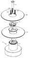
- FIG. 1shows a spin stand according to an embodiment of the present invention comprising a first (bottom) disk that remains clamped to the rotor of a spindle motor using a first disk clamp while clamping/unclamping a second (top) disk using a second disk clamp.
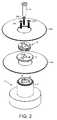
- FIG. 2shows an exploded view of the spin stand according to an embodiment of the present invention wherein a disk spacer clamps the first disk to the rotor of the spindle motor.
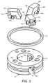
- FIG. 3shows details of the second disk clamp for clamping the second disk to the rotor, including fingers actuated outward to clamp the disk and then retracted to unclamp the disk.
- FIG. 4shows a cross-section view of the spin stand with the second disk clamp in the unclamped position according to an embodiment of the present invention.
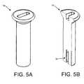
- FIG. 5Ashows a perspective view of a piston that is actuated vertically in order to clamp/unclamp the second disk according to an embodiment of the present invention.
- FIG. 5Bshows a cross-section view of the piston including a threaded screw hole according to an embodiment of the present invention.
- FIG. 6Ais a cross-section view of the spin stand wherein the first disk has been clamped to the rotor and awaiting the second disk according to an embodiment of the present invention.
- FIG. 6Bis a cross-section view of the spin stand wherein the second disk has been placed over the disk spacer before being clamped to the rotor according to an embodiment of the present invention.
- FIG. 6Cis a cross-section view of the spin stand wherein the second disk has been clamped to the rotor by the second disk clamp according to an embodiment of the present invention.
- FIG. 6Dshows a magnified view of the second disk clamp in the clamped position according to an embodiment of the present invention.
- FIGS. 1 and 2show a spin stand according to an embodiment of the present invention comprising a spindle motor 2 having a rotor 4 .
- a first disk clamp 8is operable to clamp a first disk 10 A to the rotor 4
- a second disk clamp 12is operable to clamp a second disk 10 B to the rotor 4 .
- An actuator 14is operable to clamp the second disk clamp 12 in order to clamp the second disk 10 B to the rotor 4 after the first disk 10 A has been clamped to the rotor 4 .
- the spin stand of FIG. 1may be employed in any suitable application, such as when testing various components (e.g., heads and/or disks), calibrating operating parameters (e.g., write current), certifying components as acceptable and/or binning components based on quality, servo writing the top disk with servo data (full servo write or partial servo write using seed tracks), etc.
- the spin standcomprises any suitable actuator (e.g., a voice coil motor) for actuating a head over one or both surfaces of each disk.
- Each headmay comprise a read element and a write element, and in one embodiment, a head actuated over the first (bottom) disk 10 A may comprise only a read element.
- the actuator for positioning the heads over the disk as well as the headsare conventional components not shown in the figures so as not to obscure the embodiments of the present invention.
- FIG. 3is an exploded view showing details of the second disk clamp 12 including a housing 16 having a plurality of chambers 18 A- 18 C and a finger 20 A- 20 C within each chamber 18 A- 18 C.
- Each finger 20 A- 20 Cslides about a dowel 22 A- 22 C in order to extend outward until the fingers 20 A- 20 C engage an inner edge of the second disk 10 B in order to clamp the second disk 10 B to the rotor 4 .
- the dowels 22 A- 22 Cretain each finger 20 A- 20 C within the housing 16 when the second disk clamp 12 is installed and removed.
- a plurality of screws 26 A- 26 CFIG.
- each finger 20 A- 20 Ccomprises a ramped surface 32 A- 32 C that interacts with the head of the piston 14 shown in FIG.
- the head of the piston 14comprises a cone shape such that when the piston 14 is actuated vertically downward to clamp the second disk 10 B, the head of the piston 14 presses on the ramped surfaces 32 A- 32 C thereby extending the fingers 20 A- 20 C outward until the fingers 20 A- 20 C engage an inner edge of the second disk 10 B.
- a circular elastic band 34is wrapped around the fingers 20 A- 20 C to provide a biasing force for biasing the fingers 20 A- 20 C away from the inner edge of the second disk 10 B.
- each finger 20 A- 20 Cmay comprise a suitable slot 36 A- 36 C for receiving the circular elastic band 34 .
- the piston 14is moved vertically upward allowing the circular elastic band 34 to retract the fingers 20 A- 20 C.
- the first disk 10 Aremains clamped because the screws continue to apply the clamping force to the spacer 8 through the housing 16 .
- FIG. 4is a cross sectional view of the spin stand according to an embodiment of the present invention showing the disk spacer 8 clamping the first disk 10 A via screws 26 A- 26 C compressing the housing 16 onto the disk spacer 8 .
- the piston 14is shown in the up position so that the second disk 10 B is unclamped and the circular elastic band 34 biases the fingers 20 A- 20 C away from the first disk 10 B into their retracted position.
- FIG. 5Ashows a perspective view of the piston 14 and FIG. 5B shows a cross-section view of the piston 14 .
- the piston 14may be actuated in any suitable manner in order to clamp and unclamp the second disk clamp 12 .
- a threaded screw hole 36is bored into the bottom of the piston 14 for receiving a screw (not shown), where the piston 14 may be actuated up and down by turning the screw.
- a diaphragmmay be coupled to the piston 14 (e.g., using a screw inserted into the screw hole 36 ).
- the diaphragm chambermay be filled with air using a suitable pump in order to push the piston 14 into the up position (unclamped position), and then the air sucked out of the diaphragm chamber using a suitable vacuum in order to pull the piston into the down position (clamped position).
- Other embodimentsmay employ springs to bias the piston 14 either up or down, and a suitable pump or vacuum to move the piston 14 opposite the biasing force.
- the piston 14may be moved into the clamped position using a suitable mechanical actuator (e.g., pump or vacuum), and then to unclamp the second disk 10 B, the actuator is turned off so that the force of the circular elastic band 34 retracts the fingers 20 A- 20 C causing the piston 14 to move up into the unclamped position.
- a suitable mechanical actuatore.g., pump or vacuum
- Other types of elastic membersmay be employed to retract the fingers 20 A- 20 C such as a spring integrated within each chamber 18 A- 18 C of the housing 16 ( FIG. 3 ).
- an end usermay manually press the fingers 20 A- 20 C back into their unclamped position (i.e., an elastic member such as the circular elastic band 34 of FIG. 3 may not be needed to retract the fingers 20 A- 20 C).
- FIGS. 6A-6Dillustrate operation of the spin stand according to an embodiment of the present invention, wherein FIG. 6A shows a first disk 10 A clamped to the rotor 4 by a user manually tightening screws 26 A- 26 C so that the housing 16 presses down on the spacer 8 .
- a second disk 10 Bis placed over the top surface of the spacer 8 as shown in FIG. 6B and then the actuator energized to pull the piston 14 into the down position.
- FIG. 6Cshows the piston 14 in the down position thereby extending the fingers (e.g., finger 20 A) outward to engage an inner edge of the second disk 10 B.
- FIG. 6Ashows a first disk 10 A clamped to the rotor 4 by a user manually tightening screws 26 A- 26 C so that the housing 16 presses down on the spacer 8 .
- a second disk 10 Bis placed over the top surface of the spacer 8 as shown in FIG. 6B and then the actuator energized to pull the piston 14 into the down position.
- servo datamay be written to the first disk surface 10 A using any suitable technique.
- the servo datamay be written by the spin stand after clamping the first disk 10 A to the rotor 4 .
- the servo datamay be written to the first disk 10 A before clamping it to the spin stand.
- the second disk 10 Bmay then be clamped to the spin stand in order to perform any suitable operation facilitated by the servo data written on the first disk 10 A.
- the servo data on the first disk 10 Amay be read in order to servo the head(s) over the second disk 10 B.
- test datamay be written to a surface of the second disk 10 B. Any suitable test data may be written, such as servo data or a periodic pattern (e.g., a 2T pattern). The test data may then be read from the second disk 10 B in order to perform any suitable operation, such as verifying the quality of the second disk 10 B and/or the head(s). In yet another embodiment, various parameters may be calibrated (e.g., optimal write current, read bias current, radial and linear density, etc.) for a vendor specific head/disk combination.
- any suitable test datamay be written, such as servo data or a periodic pattern (e.g., a 2T pattern).
- the test datamay then be read from the second disk 10 B in order to perform any suitable operation, such as verifying the quality of the second disk 10 B and/or the head(s).
- various parametersmay be calibrated (e.g., optimal write current, read bias current, radial and linear density, etc.) for a vendor specific head/disk combination.
- the qualification, calibration, or other testingmay require the second disk 10 B be unclamped from the spin stand, heated in an oven, and then re-clamped to the spin stand for further testing.
- the spin standmay be used to process the top disks in an assembly line fashion, such as serving on the first (bottom) disk 10 A while servo writing the second (top) disk 10 B (either full servo write or partial servo write of seed patterns). Accordingly, the dual disk clamp disclosed above in the embodiments of the present invention facilitates the clamping and unclamping of a second (top) disk 10 B while a first (bottom) disk 10 A remains clamped to the spin stand.
- the spacer 8( FIG. 2 ) may be fastened to the rotor 4 using a different technique, such as with screws that only pass through the spacer 8 and not the housing 16 of the second disk clamp 12 .
- the top surface of the spacer 8may comprise recesses for receiving the screw heads so that the second disk 10 B lies flat on the top surface of the spacer 8 .
- the second disk clamp 12comprises three fingers 20 A- 20 C, whereas other embodiments may comprise a lesser or greater number of fingers.
- the disk spacer 8may be integrally formed with at least part of the second disk clamp 12 (e.g., using suitable injection molding plastic techniques).
- the fingers 20 A- 20 Cmay be connected to the housing 16 of the second disk clamp 12 , such as fingers made from flexible plastic strips having a base connected to the housing 16 .
- the fingersthemselves may exhibit an elasticity that biases the fingers away from the inner edge 38 of the second disk 10 B while in the unclamped position (i.e., a separate biasing element such as the circular elastic band 34 of FIG. 3 may not be needed).
Landscapes
- Holding Or Fastening Of Disk On Rotational Shaft (AREA)
Abstract
Description
Claims (10)
Priority Applications (3)
| Application Number | Priority Date | Filing Date | Title |
|---|---|---|---|
| US12/718,910US8331056B2 (en) | 2010-03-05 | 2010-03-05 | Spin stand comprising a dual disk clamp |
| CN201110057859.2ACN102270478B (en) | 2010-03-05 | 2011-03-04 | Comprise the swivel mount of double plate plate clamp |
| HK11114101.4AHK1159844B (en) | 2010-03-05 | 2011-12-30 | Spin stand comprising a dual disk clamp |
Applications Claiming Priority (1)
| Application Number | Priority Date | Filing Date | Title |
|---|---|---|---|
| US12/718,910US8331056B2 (en) | 2010-03-05 | 2010-03-05 | Spin stand comprising a dual disk clamp |
Publications (2)
| Publication Number | Publication Date |
|---|---|
| US20110219389A1 US20110219389A1 (en) | 2011-09-08 |
| US8331056B2true US8331056B2 (en) | 2012-12-11 |
Family
ID=44532395
Family Applications (1)
| Application Number | Title | Priority Date | Filing Date |
|---|---|---|---|
| US12/718,910Expired - Fee RelatedUS8331056B2 (en) | 2010-03-05 | 2010-03-05 | Spin stand comprising a dual disk clamp |
Country Status (2)
| Country | Link |
|---|---|
| US (1) | US8331056B2 (en) |
| CN (1) | CN102270478B (en) |
Cited By (68)
| Publication number | Priority date | Publication date | Assignee | Title |
|---|---|---|---|---|
| US20130107396A1 (en)* | 2011-11-02 | 2013-05-02 | Donald L. Ekhoff | Vacuum clearing of spindle particulates |
| US8828566B2 (en) | 2010-05-21 | 2014-09-09 | Wd Media (Singapore) Pte. Ltd. | Perpendicular magnetic recording disc |
| US8859118B2 (en) | 2010-01-08 | 2014-10-14 | Wd Media (Singapore) Pte. Ltd. | Perpendicular magnetic recording medium |
| US8867322B1 (en) | 2013-05-07 | 2014-10-21 | WD Media, LLC | Systems and methods for providing thermal barrier bilayers for heat assisted magnetic recording media |
| US8877359B2 (en) | 2008-12-05 | 2014-11-04 | Wd Media (Singapore) Pte. Ltd. | Magnetic disk and method for manufacturing same |
| US8908315B2 (en) | 2010-03-29 | 2014-12-09 | Wd Media (Singapore) Pte. Ltd. | Evaluation method of magnetic disk, manufacturing method of magnetic disk, and magnetic disk |
| US8941950B2 (en) | 2012-05-23 | 2015-01-27 | WD Media, LLC | Underlayers for heat assisted magnetic recording (HAMR) media |
| US8947987B1 (en) | 2013-05-03 | 2015-02-03 | WD Media, LLC | Systems and methods for providing capping layers for heat assisted magnetic recording media |
| US8951651B2 (en) | 2010-05-28 | 2015-02-10 | Wd Media (Singapore) Pte. Ltd. | Perpendicular magnetic recording disk |
| US8980076B1 (en) | 2009-05-26 | 2015-03-17 | WD Media, LLC | Electro-deposited passivation coatings for patterned media |
| US8993134B2 (en) | 2012-06-29 | 2015-03-31 | Western Digital Technologies, Inc. | Electrically conductive underlayer to grow FePt granular media with (001) texture on glass substrates |
| US8995078B1 (en) | 2014-09-25 | 2015-03-31 | WD Media, LLC | Method of testing a head for contamination |
| US9001630B1 (en) | 2011-03-08 | 2015-04-07 | Western Digital Technologies, Inc. | Energy assisted magnetic recording medium capable of suppressing high DC readback noise |
| US9005782B2 (en) | 2008-03-30 | 2015-04-14 | WD Media, LLC | Magnetic disk and method of manufacturing the same |
| US9025264B1 (en) | 2011-03-10 | 2015-05-05 | WD Media, LLC | Methods for measuring media performance associated with adjacent track interference |
| US9028985B2 (en) | 2011-03-31 | 2015-05-12 | WD Media, LLC | Recording media with multiple exchange coupled magnetic layers |
| US9029308B1 (en) | 2012-03-28 | 2015-05-12 | WD Media, LLC | Low foam media cleaning detergent |
| US9034492B1 (en) | 2013-01-11 | 2015-05-19 | WD Media, LLC | Systems and methods for controlling damping of magnetic media for heat assisted magnetic recording |
| US9042053B1 (en) | 2014-06-24 | 2015-05-26 | WD Media, LLC | Thermally stabilized perpendicular magnetic recording medium |
| US9047903B2 (en) | 2008-03-26 | 2015-06-02 | Wd Media (Singapore) Pte. Ltd. | Perpendicular magnetic recording medium and process for manufacture thereof |
| US9047880B1 (en) | 2011-12-20 | 2015-06-02 | WD Media, LLC | Heat assisted magnetic recording method for media having moment keeper layer |
| US9064521B1 (en) | 2011-03-25 | 2015-06-23 | WD Media, LLC | Manufacturing of hard masks for patterning magnetic media |
| US9082447B1 (en) | 2014-09-22 | 2015-07-14 | WD Media, LLC | Determining storage media substrate material type |
| US9093122B1 (en) | 2013-04-05 | 2015-07-28 | WD Media, LLC | Systems and methods for improving accuracy of test measurements involving aggressor tracks written to disks of hard disk drives |
| US9093100B2 (en) | 2008-03-17 | 2015-07-28 | Wd Media (Singapore) Pte. Ltd. | Magnetic recording medium including tailored exchange coupling layer and manufacturing method of the same |
| US9142241B2 (en) | 2009-03-30 | 2015-09-22 | Wd Media (Singapore) Pte. Ltd. | Perpendicular magnetic recording medium and method of manufacturing the same |
| US9153268B1 (en) | 2013-02-19 | 2015-10-06 | WD Media, LLC | Lubricants comprising fluorinated graphene nanoribbons for magnetic recording media structure |
| US9159350B1 (en) | 2014-07-02 | 2015-10-13 | WD Media, LLC | High damping cap layer for magnetic recording media |
| US9177586B2 (en) | 2008-09-30 | 2015-11-03 | WD Media (Singapore), LLC | Magnetic disk and manufacturing method thereof |
| US9177585B1 (en) | 2013-10-23 | 2015-11-03 | WD Media, LLC | Magnetic media capable of improving magnetic properties and thermal management for heat-assisted magnetic recording |
| US9183867B1 (en) | 2013-02-21 | 2015-11-10 | WD Media, LLC | Systems and methods for forming implanted capping layers in magnetic media for magnetic recording |
| US9190094B2 (en) | 2013-04-04 | 2015-11-17 | Western Digital (Fremont) | Perpendicular recording media with grain isolation initiation layer and exchange breaking layer for signal-to-noise ratio enhancement |
| US9196283B1 (en) | 2013-03-13 | 2015-11-24 | Western Digital (Fremont), Llc | Method for providing a magnetic recording transducer using a chemical buffer |
| US9218850B1 (en) | 2014-12-23 | 2015-12-22 | WD Media, LLC | Exchange break layer for heat-assisted magnetic recording media |
| US9227324B1 (en) | 2014-09-25 | 2016-01-05 | WD Media, LLC | Mandrel for substrate transport system with notch |
| US9240204B2 (en) | 2010-05-21 | 2016-01-19 | Wd Media (Singapore) Pte. Ltd. | Perpendicular magnetic recording disc |
| US9257134B1 (en) | 2014-12-24 | 2016-02-09 | Western Digital Technologies, Inc. | Allowing fast data zone switches on data storage devices |
| US9269480B1 (en) | 2012-03-30 | 2016-02-23 | WD Media, LLC | Systems and methods for forming magnetic recording media with improved grain columnar growth for energy assisted magnetic recording |
| US9275669B1 (en) | 2015-03-31 | 2016-03-01 | WD Media, LLC | TbFeCo in PMR media for SNR improvement |
| US9280998B1 (en) | 2015-03-30 | 2016-03-08 | WD Media, LLC | Acidic post-sputter wash for magnetic recording media |
| US9296082B1 (en) | 2013-06-11 | 2016-03-29 | WD Media, LLC | Disk buffing apparatus with abrasive tape loading pad having a vibration absorbing layer |
| US9330685B1 (en) | 2009-11-06 | 2016-05-03 | WD Media, LLC | Press system for nano-imprinting of recording media with a two step pressing method |
| US9339978B1 (en) | 2009-11-06 | 2016-05-17 | WD Media, LLC | Press system with interleaved embossing foil holders for nano-imprinting of recording media |
| US9349404B2 (en) | 2010-05-28 | 2016-05-24 | Wd Media (Singapore) Pte. Ltd | Perpendicular magnetic recording disc |
| US9382496B1 (en) | 2013-12-19 | 2016-07-05 | Western Digital Technologies, Inc. | Lubricants with high thermal stability for heat-assisted magnetic recording |
| US9389135B2 (en) | 2013-09-26 | 2016-07-12 | WD Media, LLC | Systems and methods for calibrating a load cell of a disk burnishing machine |
| US9401300B1 (en) | 2014-12-18 | 2016-07-26 | WD Media, LLC | Media substrate gripper including a plurality of snap-fit fingers |
| US9406329B1 (en) | 2015-11-30 | 2016-08-02 | WD Media, LLC | HAMR media structure with intermediate layer underlying a magnetic recording layer having multiple sublayers |
| US9406330B1 (en) | 2013-06-19 | 2016-08-02 | WD Media, LLC | Method for HDD disk defect source detection |
| US9431045B1 (en) | 2014-04-25 | 2016-08-30 | WD Media, LLC | Magnetic seed layer used with an unbalanced soft underlayer |
| US9447368B1 (en) | 2014-02-18 | 2016-09-20 | WD Media, LLC | Detergent composition with low foam and high nickel solubility |
| US9449633B1 (en) | 2014-11-06 | 2016-09-20 | WD Media, LLC | Smooth structures for heat-assisted magnetic recording media |
| US9472227B2 (en) | 2010-06-22 | 2016-10-18 | Wd Media (Singapore) Pte. Ltd. | Perpendicular magnetic recording media and methods for producing the same |
| US9542968B1 (en) | 2010-08-20 | 2017-01-10 | WD Media, LLC | Single layer small grain size FePT:C film for heat assisted magnetic recording media |
| US9558778B2 (en) | 2009-03-28 | 2017-01-31 | Wd Media (Singapore) Pte. Ltd. | Lubricant compound for magnetic disk and magnetic disk |
| US9581510B1 (en) | 2013-12-16 | 2017-02-28 | Western Digital Technologies, Inc. | Sputter chamber pressure gauge with vibration absorber |
| US9607646B2 (en) | 2013-07-30 | 2017-03-28 | WD Media, LLC | Hard disk double lubrication layer |
| US9685184B1 (en) | 2014-09-25 | 2017-06-20 | WD Media, LLC | NiFeX-based seed layer for magnetic recording media |
| US9818442B2 (en) | 2014-12-01 | 2017-11-14 | WD Media, LLC | Magnetic media having improved magnetic grain size distribution and intergranular segregation |
| US9822441B2 (en) | 2015-03-31 | 2017-11-21 | WD Media, LLC | Iridium underlayer for heat assisted magnetic recording media |
| US9824711B1 (en) | 2014-02-14 | 2017-11-21 | WD Media, LLC | Soft underlayer for heat assisted magnetic recording media |
| US9990940B1 (en) | 2014-12-30 | 2018-06-05 | WD Media, LLC | Seed structure for perpendicular magnetic recording media |
| US10054363B2 (en) | 2014-08-15 | 2018-08-21 | WD Media, LLC | Method and apparatus for cryogenic dynamic cooling |
| US10083715B2 (en) | 2010-05-28 | 2018-09-25 | WD Media (Singapore) Pte.Ltd. | Method of manufacturing a perpendicular magnetic disc |
| US10115428B1 (en) | 2013-02-15 | 2018-10-30 | Wd Media, Inc. | HAMR media structure having an anisotropic thermal barrier layer |
| US10121506B1 (en) | 2015-12-29 | 2018-11-06 | WD Media, LLC | Magnetic-recording medium including a carbon overcoat implanted with nitrogen and hydrogen |
| US10236026B1 (en) | 2015-11-06 | 2019-03-19 | WD Media, LLC | Thermal barrier layers and seed layers for control of thermal and structural properties of HAMR media |
| US11074934B1 (en) | 2015-09-25 | 2021-07-27 | Western Digital Technologies, Inc. | Heat assisted magnetic recording (HAMR) media with Curie temperature reduction layer |
Families Citing this family (1)
| Publication number | Priority date | Publication date | Assignee | Title |
|---|---|---|---|---|
| CN105082162B (en)* | 2014-05-12 | 2017-07-18 | 连秉然 | CD automatic grabbing device |
Citations (43)
| Publication number | Priority date | Publication date | Assignee | Title |
|---|---|---|---|---|
| US4627288A (en) | 1985-08-12 | 1986-12-09 | Guzik Technical Enterprises | Bearing unloading mechanism for disc clamping unit |
| US4755981A (en) | 1987-01-27 | 1988-07-05 | Ekhoff Donald L | Spindle clamp for removable disks |
| US4945432A (en)* | 1988-03-31 | 1990-07-31 | Hoya Electronics Corporation | Magnetic disk drive with brittle disks |
| US5012363A (en) | 1988-02-03 | 1991-04-30 | International Business Machines Corporation | Servo pattern writing method for a disk storage device |
| US5048005A (en) | 1989-10-10 | 1991-09-10 | Ekhoff Donald L | Spindle clamp having a unitary lock member |
| US5056082A (en) | 1989-06-12 | 1991-10-08 | Ekhoff Donald L | Apparatus for clamping removable disks |
| US5243481A (en) | 1991-09-25 | 1993-09-07 | Integral Peripherals, Inc. | Clamp for information storage disk |
| US5249090A (en) | 1991-03-14 | 1993-09-28 | Wolfgang Fehse | Disk store with device for fixing the disk pack on its hub such that it can be removed |
| US5367418A (en)* | 1992-11-13 | 1994-11-22 | Maxtor Corporation | Spin motor assembly that contains an O-ring which supports a disk in both the radial and axial directions |
| US5485328A (en) | 1994-05-04 | 1996-01-16 | Seagate Technology, Inc. | System for removing a clamp from a disc drive hub assembly |
| US5542685A (en) | 1994-05-06 | 1996-08-06 | Komag, Inc. | Memory disk clamp and method |
| US5644564A (en) | 1995-03-17 | 1997-07-01 | Phase Metrics | Vacuum chuck for rotating data discs |
| US5894374A (en) | 1996-12-17 | 1999-04-13 | Phase Metrics, Inc. | Method and apparatus for providing a clock assembly |
| US5912784A (en) | 1996-11-19 | 1999-06-15 | Seagate Technology, Inc. | Dual member disc clamp for uniform clamping load distribution |
| US5917677A (en) | 1995-12-18 | 1999-06-29 | Seagate Technology, Inc. | Disk drive motor spindle hub assembly with separately formed hub ceramic flange attachment |
| US6130801A (en) | 1997-11-07 | 2000-10-10 | Seagate Technology, Inc. | Composite disc spacer for a disc drive |
| US6229664B1 (en) | 1998-08-24 | 2001-05-08 | International Business Machines Corporation | Head-disk interface tester with optically servo controlled rotary voice coil motor actuator |
| US6304407B1 (en) | 1998-10-27 | 2001-10-16 | Maxtor Corporation | Self-writing of servo patterns based on printed reference pattern in rotating disk drive |
| US6373243B1 (en) | 1999-10-12 | 2002-04-16 | Fuji Electric Co., Ltd. | Magnetic media tester for testing a servo signal prerecorded in a magnetic media |
| US6462902B1 (en)* | 1998-06-05 | 2002-10-08 | Seagate Technology Llc | Independent clamping spacers in a disc drive assembly |
| US6538838B1 (en) | 1999-02-22 | 2003-03-25 | Seagate Technology Llc | Method and apparatus for closed-loop spin-stand testing |
| US20030099050A1 (en) | 2001-11-27 | 2003-05-29 | Katsuyoshi Kitagawa | Apparatus and method for writing head positioning information to disk medium |
| US20030103292A1 (en)* | 2001-12-04 | 2003-06-05 | Samsung Electronics Co., Ltd | Disk chuck |
| US6578257B1 (en) | 1998-04-16 | 2003-06-17 | Seagate Technology Llc | Semi-automated media rework tool |
| US6600628B2 (en) | 2001-04-10 | 2003-07-29 | Kla-Tencor Corporation | Air centering disk chuck |
| US6683744B2 (en) | 2000-07-19 | 2004-01-27 | Fuji Electric Co., Ltd. | Magnetic disk evaluation apparatus and method |
| US6696831B2 (en) | 2000-09-13 | 2004-02-24 | International Manufacturing And Engineering Services Co., Ltd. | Testing apparatus and method for testing magnetic head and/or magnetic disk |
| US6738205B1 (en) | 2001-07-08 | 2004-05-18 | Maxtor Corporation | Self-writing of servo patterns in disk drives |
| US6798614B2 (en) | 2001-06-01 | 2004-09-28 | Seagate Technology Llc | Releasable disc clamping assembly |
| US6836461B2 (en) | 2001-03-28 | 2004-12-28 | International Business Machines Corporation | Clamping device for removable disks |
| US6947244B2 (en) | 2001-11-29 | 2005-09-20 | Hitachi Global Storage Technologies Japan, Ltd. | Servo pattern writing method and apparatus thereof |
| US6965489B1 (en) | 2004-01-31 | 2005-11-15 | Western Digital Technologies, Inc. | Using an external spiral servo writer to write reference servo sectors and spiral tracks to a disk to facilitate writing product servo sectors to the disk |
| US7131346B1 (en) | 2004-10-15 | 2006-11-07 | Western Digital (Fremont), Inc. | Spin stand testing system with fine positioner for head stack assembly |
| US7154699B2 (en) | 2001-07-02 | 2006-12-26 | Seagate Technology Llc | High bandwidth large stroke spin-stand |
| US7158330B2 (en) | 2001-11-08 | 2007-01-02 | Samsung Electronics Co., Ltd. | Method and apparatus for servo track writing by track following on a dedicated servo disk on a fluid spindle bearing |
| US20070081268A1 (en) | 2005-10-11 | 2007-04-12 | Samsung Electronics Co., Ltd. | Method of writing a reference servo signal of hard disk drive and apparatus suitable therefor |
| US7206157B2 (en) | 2004-07-08 | 2007-04-17 | Matsushita Electric Industrial Co., Ltd. | Systems and methods for two-step self-servowriting using optimal intermediate pattern |
| US7275302B2 (en) | 2003-12-09 | 2007-10-02 | Seagate Technology Llc | Method of forming a disc pack |
| US20080002279A1 (en) | 2006-06-30 | 2008-01-03 | Kabushiki Kaisha Toshiba | Method and apparatus for writing a spiral servo pattern on a disk in a disk drive |
| US20080062563A1 (en) | 2006-09-08 | 2008-03-13 | Xyratex Technology Limited | Apparatus and method for attaching a disk to a spindle of a spinstand |
| US20080062855A1 (en) | 2006-09-08 | 2008-03-13 | Xyratex Technology Limited | Apparatus for attaching a disk to a spindle of a spinstand, methods for attaching and detaching a disk to and from a spindle of a spinstand and a movable stage |
| US7499244B2 (en) | 2005-02-03 | 2009-03-03 | Samsung Electronics Co., Ltd. | Disk holder for off-line servo-track writer |
| US8218260B2 (en) | 2010-03-05 | 2012-07-10 | Wd Media, Inc. | Processing disks on a spin stand |
Family Cites Families (1)
| Publication number | Priority date | Publication date | Assignee | Title |
|---|---|---|---|---|
| JPH06131783A (en)* | 1992-10-19 | 1994-05-13 | Asahi Corp:Kk | Disk holder |
- 2010
- 2010-03-05USUS12/718,910patent/US8331056B2/ennot_activeExpired - Fee Related
- 2011
- 2011-03-04CNCN201110057859.2Apatent/CN102270478B/enactiveActive
Patent Citations (45)
| Publication number | Priority date | Publication date | Assignee | Title |
|---|---|---|---|---|
| US4627288A (en) | 1985-08-12 | 1986-12-09 | Guzik Technical Enterprises | Bearing unloading mechanism for disc clamping unit |
| US4755981A (en) | 1987-01-27 | 1988-07-05 | Ekhoff Donald L | Spindle clamp for removable disks |
| US5012363A (en) | 1988-02-03 | 1991-04-30 | International Business Machines Corporation | Servo pattern writing method for a disk storage device |
| US4945432A (en)* | 1988-03-31 | 1990-07-31 | Hoya Electronics Corporation | Magnetic disk drive with brittle disks |
| US5056082A (en) | 1989-06-12 | 1991-10-08 | Ekhoff Donald L | Apparatus for clamping removable disks |
| US5048005A (en) | 1989-10-10 | 1991-09-10 | Ekhoff Donald L | Spindle clamp having a unitary lock member |
| US5249090A (en) | 1991-03-14 | 1993-09-28 | Wolfgang Fehse | Disk store with device for fixing the disk pack on its hub such that it can be removed |
| US5243481A (en) | 1991-09-25 | 1993-09-07 | Integral Peripherals, Inc. | Clamp for information storage disk |
| US5367418A (en)* | 1992-11-13 | 1994-11-22 | Maxtor Corporation | Spin motor assembly that contains an O-ring which supports a disk in both the radial and axial directions |
| US5485328A (en) | 1994-05-04 | 1996-01-16 | Seagate Technology, Inc. | System for removing a clamp from a disc drive hub assembly |
| US5542685A (en) | 1994-05-06 | 1996-08-06 | Komag, Inc. | Memory disk clamp and method |
| US5644564A (en) | 1995-03-17 | 1997-07-01 | Phase Metrics | Vacuum chuck for rotating data discs |
| US5917677A (en) | 1995-12-18 | 1999-06-29 | Seagate Technology, Inc. | Disk drive motor spindle hub assembly with separately formed hub ceramic flange attachment |
| US5912784A (en) | 1996-11-19 | 1999-06-15 | Seagate Technology, Inc. | Dual member disc clamp for uniform clamping load distribution |
| US5894374A (en) | 1996-12-17 | 1999-04-13 | Phase Metrics, Inc. | Method and apparatus for providing a clock assembly |
| US6130801A (en) | 1997-11-07 | 2000-10-10 | Seagate Technology, Inc. | Composite disc spacer for a disc drive |
| US6578257B1 (en) | 1998-04-16 | 2003-06-17 | Seagate Technology Llc | Semi-automated media rework tool |
| US6462902B1 (en)* | 1998-06-05 | 2002-10-08 | Seagate Technology Llc | Independent clamping spacers in a disc drive assembly |
| US6229664B1 (en) | 1998-08-24 | 2001-05-08 | International Business Machines Corporation | Head-disk interface tester with optically servo controlled rotary voice coil motor actuator |
| US6304407B1 (en) | 1998-10-27 | 2001-10-16 | Maxtor Corporation | Self-writing of servo patterns based on printed reference pattern in rotating disk drive |
| US6538838B1 (en) | 1999-02-22 | 2003-03-25 | Seagate Technology Llc | Method and apparatus for closed-loop spin-stand testing |
| US6373243B1 (en) | 1999-10-12 | 2002-04-16 | Fuji Electric Co., Ltd. | Magnetic media tester for testing a servo signal prerecorded in a magnetic media |
| US6683744B2 (en) | 2000-07-19 | 2004-01-27 | Fuji Electric Co., Ltd. | Magnetic disk evaluation apparatus and method |
| US6696831B2 (en) | 2000-09-13 | 2004-02-24 | International Manufacturing And Engineering Services Co., Ltd. | Testing apparatus and method for testing magnetic head and/or magnetic disk |
| US6836461B2 (en) | 2001-03-28 | 2004-12-28 | International Business Machines Corporation | Clamping device for removable disks |
| US6600628B2 (en) | 2001-04-10 | 2003-07-29 | Kla-Tencor Corporation | Air centering disk chuck |
| US6798614B2 (en) | 2001-06-01 | 2004-09-28 | Seagate Technology Llc | Releasable disc clamping assembly |
| US7154699B2 (en) | 2001-07-02 | 2006-12-26 | Seagate Technology Llc | High bandwidth large stroke spin-stand |
| US6738205B1 (en) | 2001-07-08 | 2004-05-18 | Maxtor Corporation | Self-writing of servo patterns in disk drives |
| US7158330B2 (en) | 2001-11-08 | 2007-01-02 | Samsung Electronics Co., Ltd. | Method and apparatus for servo track writing by track following on a dedicated servo disk on a fluid spindle bearing |
| US20030099050A1 (en) | 2001-11-27 | 2003-05-29 | Katsuyoshi Kitagawa | Apparatus and method for writing head positioning information to disk medium |
| US6947244B2 (en) | 2001-11-29 | 2005-09-20 | Hitachi Global Storage Technologies Japan, Ltd. | Servo pattern writing method and apparatus thereof |
| US20030103292A1 (en)* | 2001-12-04 | 2003-06-05 | Samsung Electronics Co., Ltd | Disk chuck |
| US6954330B2 (en) | 2001-12-04 | 2005-10-11 | Samsung Electronics, Co., Ltd. | Disk chuck |
| US7275302B2 (en) | 2003-12-09 | 2007-10-02 | Seagate Technology Llc | Method of forming a disc pack |
| US6965489B1 (en) | 2004-01-31 | 2005-11-15 | Western Digital Technologies, Inc. | Using an external spiral servo writer to write reference servo sectors and spiral tracks to a disk to facilitate writing product servo sectors to the disk |
| US7206157B2 (en) | 2004-07-08 | 2007-04-17 | Matsushita Electric Industrial Co., Ltd. | Systems and methods for two-step self-servowriting using optimal intermediate pattern |
| US7131346B1 (en) | 2004-10-15 | 2006-11-07 | Western Digital (Fremont), Inc. | Spin stand testing system with fine positioner for head stack assembly |
| US7499244B2 (en) | 2005-02-03 | 2009-03-03 | Samsung Electronics Co., Ltd. | Disk holder for off-line servo-track writer |
| US20070081268A1 (en) | 2005-10-11 | 2007-04-12 | Samsung Electronics Co., Ltd. | Method of writing a reference servo signal of hard disk drive and apparatus suitable therefor |
| US7333286B2 (en) | 2005-10-11 | 2008-02-19 | Samsung Electronics Co., Ltd. | Method of writing a reference servo signal of hard disk drive and apparatus suitable therefor |
| US20080002279A1 (en) | 2006-06-30 | 2008-01-03 | Kabushiki Kaisha Toshiba | Method and apparatus for writing a spiral servo pattern on a disk in a disk drive |
| US20080062563A1 (en) | 2006-09-08 | 2008-03-13 | Xyratex Technology Limited | Apparatus and method for attaching a disk to a spindle of a spinstand |
| US20080062855A1 (en) | 2006-09-08 | 2008-03-13 | Xyratex Technology Limited | Apparatus for attaching a disk to a spindle of a spinstand, methods for attaching and detaching a disk to and from a spindle of a spinstand and a movable stage |
| US8218260B2 (en) | 2010-03-05 | 2012-07-10 | Wd Media, Inc. | Processing disks on a spin stand |
Cited By (70)
| Publication number | Priority date | Publication date | Assignee | Title |
|---|---|---|---|---|
| US9093100B2 (en) | 2008-03-17 | 2015-07-28 | Wd Media (Singapore) Pte. Ltd. | Magnetic recording medium including tailored exchange coupling layer and manufacturing method of the same |
| US9047903B2 (en) | 2008-03-26 | 2015-06-02 | Wd Media (Singapore) Pte. Ltd. | Perpendicular magnetic recording medium and process for manufacture thereof |
| US9005782B2 (en) | 2008-03-30 | 2015-04-14 | WD Media, LLC | Magnetic disk and method of manufacturing the same |
| US9177586B2 (en) | 2008-09-30 | 2015-11-03 | WD Media (Singapore), LLC | Magnetic disk and manufacturing method thereof |
| US9984715B2 (en) | 2008-09-30 | 2018-05-29 | WD Media, LLC | Magnetic disk and manufacturing method thereof |
| US8877359B2 (en) | 2008-12-05 | 2014-11-04 | Wd Media (Singapore) Pte. Ltd. | Magnetic disk and method for manufacturing same |
| US9558778B2 (en) | 2009-03-28 | 2017-01-31 | Wd Media (Singapore) Pte. Ltd. | Lubricant compound for magnetic disk and magnetic disk |
| US9142241B2 (en) | 2009-03-30 | 2015-09-22 | Wd Media (Singapore) Pte. Ltd. | Perpendicular magnetic recording medium and method of manufacturing the same |
| US8980076B1 (en) | 2009-05-26 | 2015-03-17 | WD Media, LLC | Electro-deposited passivation coatings for patterned media |
| US9330685B1 (en) | 2009-11-06 | 2016-05-03 | WD Media, LLC | Press system for nano-imprinting of recording media with a two step pressing method |
| US9339978B1 (en) | 2009-11-06 | 2016-05-17 | WD Media, LLC | Press system with interleaved embossing foil holders for nano-imprinting of recording media |
| US8859118B2 (en) | 2010-01-08 | 2014-10-14 | Wd Media (Singapore) Pte. Ltd. | Perpendicular magnetic recording medium |
| US8908315B2 (en) | 2010-03-29 | 2014-12-09 | Wd Media (Singapore) Pte. Ltd. | Evaluation method of magnetic disk, manufacturing method of magnetic disk, and magnetic disk |
| US9240204B2 (en) | 2010-05-21 | 2016-01-19 | Wd Media (Singapore) Pte. Ltd. | Perpendicular magnetic recording disc |
| US8828566B2 (en) | 2010-05-21 | 2014-09-09 | Wd Media (Singapore) Pte. Ltd. | Perpendicular magnetic recording disc |
| US9349404B2 (en) | 2010-05-28 | 2016-05-24 | Wd Media (Singapore) Pte. Ltd | Perpendicular magnetic recording disc |
| US8951651B2 (en) | 2010-05-28 | 2015-02-10 | Wd Media (Singapore) Pte. Ltd. | Perpendicular magnetic recording disk |
| US10083715B2 (en) | 2010-05-28 | 2018-09-25 | WD Media (Singapore) Pte.Ltd. | Method of manufacturing a perpendicular magnetic disc |
| US9472227B2 (en) | 2010-06-22 | 2016-10-18 | Wd Media (Singapore) Pte. Ltd. | Perpendicular magnetic recording media and methods for producing the same |
| US9542968B1 (en) | 2010-08-20 | 2017-01-10 | WD Media, LLC | Single layer small grain size FePT:C film for heat assisted magnetic recording media |
| US9001630B1 (en) | 2011-03-08 | 2015-04-07 | Western Digital Technologies, Inc. | Energy assisted magnetic recording medium capable of suppressing high DC readback noise |
| US9025264B1 (en) | 2011-03-10 | 2015-05-05 | WD Media, LLC | Methods for measuring media performance associated with adjacent track interference |
| US9064521B1 (en) | 2011-03-25 | 2015-06-23 | WD Media, LLC | Manufacturing of hard masks for patterning magnetic media |
| US9028985B2 (en) | 2011-03-31 | 2015-05-12 | WD Media, LLC | Recording media with multiple exchange coupled magnetic layers |
| US20130107396A1 (en)* | 2011-11-02 | 2013-05-02 | Donald L. Ekhoff | Vacuum clearing of spindle particulates |
| US9047880B1 (en) | 2011-12-20 | 2015-06-02 | WD Media, LLC | Heat assisted magnetic recording method for media having moment keeper layer |
| US9029308B1 (en) | 2012-03-28 | 2015-05-12 | WD Media, LLC | Low foam media cleaning detergent |
| US9269480B1 (en) | 2012-03-30 | 2016-02-23 | WD Media, LLC | Systems and methods for forming magnetic recording media with improved grain columnar growth for energy assisted magnetic recording |
| US8941950B2 (en) | 2012-05-23 | 2015-01-27 | WD Media, LLC | Underlayers for heat assisted magnetic recording (HAMR) media |
| US8993134B2 (en) | 2012-06-29 | 2015-03-31 | Western Digital Technologies, Inc. | Electrically conductive underlayer to grow FePt granular media with (001) texture on glass substrates |
| US9034492B1 (en) | 2013-01-11 | 2015-05-19 | WD Media, LLC | Systems and methods for controlling damping of magnetic media for heat assisted magnetic recording |
| US10115428B1 (en) | 2013-02-15 | 2018-10-30 | Wd Media, Inc. | HAMR media structure having an anisotropic thermal barrier layer |
| US9153268B1 (en) | 2013-02-19 | 2015-10-06 | WD Media, LLC | Lubricants comprising fluorinated graphene nanoribbons for magnetic recording media structure |
| US9183867B1 (en) | 2013-02-21 | 2015-11-10 | WD Media, LLC | Systems and methods for forming implanted capping layers in magnetic media for magnetic recording |
| US9196283B1 (en) | 2013-03-13 | 2015-11-24 | Western Digital (Fremont), Llc | Method for providing a magnetic recording transducer using a chemical buffer |
| US9190094B2 (en) | 2013-04-04 | 2015-11-17 | Western Digital (Fremont) | Perpendicular recording media with grain isolation initiation layer and exchange breaking layer for signal-to-noise ratio enhancement |
| US9093122B1 (en) | 2013-04-05 | 2015-07-28 | WD Media, LLC | Systems and methods for improving accuracy of test measurements involving aggressor tracks written to disks of hard disk drives |
| US8947987B1 (en) | 2013-05-03 | 2015-02-03 | WD Media, LLC | Systems and methods for providing capping layers for heat assisted magnetic recording media |
| US8867322B1 (en) | 2013-05-07 | 2014-10-21 | WD Media, LLC | Systems and methods for providing thermal barrier bilayers for heat assisted magnetic recording media |
| US9296082B1 (en) | 2013-06-11 | 2016-03-29 | WD Media, LLC | Disk buffing apparatus with abrasive tape loading pad having a vibration absorbing layer |
| US9406330B1 (en) | 2013-06-19 | 2016-08-02 | WD Media, LLC | Method for HDD disk defect source detection |
| US9607646B2 (en) | 2013-07-30 | 2017-03-28 | WD Media, LLC | Hard disk double lubrication layer |
| US9389135B2 (en) | 2013-09-26 | 2016-07-12 | WD Media, LLC | Systems and methods for calibrating a load cell of a disk burnishing machine |
| US9177585B1 (en) | 2013-10-23 | 2015-11-03 | WD Media, LLC | Magnetic media capable of improving magnetic properties and thermal management for heat-assisted magnetic recording |
| US9581510B1 (en) | 2013-12-16 | 2017-02-28 | Western Digital Technologies, Inc. | Sputter chamber pressure gauge with vibration absorber |
| US9382496B1 (en) | 2013-12-19 | 2016-07-05 | Western Digital Technologies, Inc. | Lubricants with high thermal stability for heat-assisted magnetic recording |
| US9824711B1 (en) | 2014-02-14 | 2017-11-21 | WD Media, LLC | Soft underlayer for heat assisted magnetic recording media |
| US9447368B1 (en) | 2014-02-18 | 2016-09-20 | WD Media, LLC | Detergent composition with low foam and high nickel solubility |
| US9431045B1 (en) | 2014-04-25 | 2016-08-30 | WD Media, LLC | Magnetic seed layer used with an unbalanced soft underlayer |
| US9042053B1 (en) | 2014-06-24 | 2015-05-26 | WD Media, LLC | Thermally stabilized perpendicular magnetic recording medium |
| US9159350B1 (en) | 2014-07-02 | 2015-10-13 | WD Media, LLC | High damping cap layer for magnetic recording media |
| US10054363B2 (en) | 2014-08-15 | 2018-08-21 | WD Media, LLC | Method and apparatus for cryogenic dynamic cooling |
| US9082447B1 (en) | 2014-09-22 | 2015-07-14 | WD Media, LLC | Determining storage media substrate material type |
| US9685184B1 (en) | 2014-09-25 | 2017-06-20 | WD Media, LLC | NiFeX-based seed layer for magnetic recording media |
| US8995078B1 (en) | 2014-09-25 | 2015-03-31 | WD Media, LLC | Method of testing a head for contamination |
| US9227324B1 (en) | 2014-09-25 | 2016-01-05 | WD Media, LLC | Mandrel for substrate transport system with notch |
| US9449633B1 (en) | 2014-11-06 | 2016-09-20 | WD Media, LLC | Smooth structures for heat-assisted magnetic recording media |
| US9818442B2 (en) | 2014-12-01 | 2017-11-14 | WD Media, LLC | Magnetic media having improved magnetic grain size distribution and intergranular segregation |
| US10783915B2 (en) | 2014-12-01 | 2020-09-22 | Western Digital Technologies, Inc. | Magnetic media having improved magnetic grain size distribution and intergranular segregation |
| US9401300B1 (en) | 2014-12-18 | 2016-07-26 | WD Media, LLC | Media substrate gripper including a plurality of snap-fit fingers |
| US9218850B1 (en) | 2014-12-23 | 2015-12-22 | WD Media, LLC | Exchange break layer for heat-assisted magnetic recording media |
| US9257134B1 (en) | 2014-12-24 | 2016-02-09 | Western Digital Technologies, Inc. | Allowing fast data zone switches on data storage devices |
| US9990940B1 (en) | 2014-12-30 | 2018-06-05 | WD Media, LLC | Seed structure for perpendicular magnetic recording media |
| US9280998B1 (en) | 2015-03-30 | 2016-03-08 | WD Media, LLC | Acidic post-sputter wash for magnetic recording media |
| US9822441B2 (en) | 2015-03-31 | 2017-11-21 | WD Media, LLC | Iridium underlayer for heat assisted magnetic recording media |
| US9275669B1 (en) | 2015-03-31 | 2016-03-01 | WD Media, LLC | TbFeCo in PMR media for SNR improvement |
| US11074934B1 (en) | 2015-09-25 | 2021-07-27 | Western Digital Technologies, Inc. | Heat assisted magnetic recording (HAMR) media with Curie temperature reduction layer |
| US10236026B1 (en) | 2015-11-06 | 2019-03-19 | WD Media, LLC | Thermal barrier layers and seed layers for control of thermal and structural properties of HAMR media |
| US9406329B1 (en) | 2015-11-30 | 2016-08-02 | WD Media, LLC | HAMR media structure with intermediate layer underlying a magnetic recording layer having multiple sublayers |
| US10121506B1 (en) | 2015-12-29 | 2018-11-06 | WD Media, LLC | Magnetic-recording medium including a carbon overcoat implanted with nitrogen and hydrogen |
Also Published As
| Publication number | Publication date |
|---|---|
| US20110219389A1 (en) | 2011-09-08 |
| HK1159844A1 (en) | 2012-08-03 |
| CN102270478B (en) | 2015-09-16 |
| CN102270478A (en) | 2011-12-07 |
Similar Documents
| Publication | Publication Date | Title |
|---|---|---|
| US8331056B2 (en) | Spin stand comprising a dual disk clamp | |
| US8218260B2 (en) | Processing disks on a spin stand | |
| US20070046286A1 (en) | Magnetic head tester and method of manufacturing magnetic disk drive | |
| KR940006851B1 (en) | Stable stretched surface recording medium | |
| US6456463B1 (en) | Actuator assembly having an arm with a spring mount for mounting to an assembly spacer | |
| US20030103292A1 (en) | Disk chuck | |
| US7499244B2 (en) | Disk holder for off-line servo-track writer | |
| JP4117104B2 (en) | Disk medium incorporating method and apparatus | |
| HK1159844B (en) | Spin stand comprising a dual disk clamp | |
| HK1158807B (en) | Processing disks on a spin stand | |
| US20050264927A1 (en) | Removable disk pack hub and clamp for media servowriter | |
| US20070165327A1 (en) | Apparatus to fix a disk and a method thereof | |
| US20080170325A1 (en) | Disk Centering Assembly And Spindle Hub | |
| US10460758B2 (en) | Disk clamping mechanism including annular ring member | |
| US20180158477A1 (en) | Disk device with stopper for movable member | |
| KR100594283B1 (en) | External hub assembly of hard disk drive, spindle motor and external hub assembly including same | |
| US7650686B2 (en) | Servo track writer clockhead radius jig | |
| JP2002308239A (en) | Label sticking tool | |
| US8458891B2 (en) | Method of centering a disk of hard disk drive | |
| JP2007509452A (en) | Turntable with position setting | |
| US20070204282A1 (en) | Optical Scanning Apparatus For Various Appliances For Recording Or Reproducing Data Or Information Using An Optical Recording Medium | |
| KR100500235B1 (en) | Disc centering device | |
| Guo et al. | Achieving Minimal Repeatable Runout | |
| JP2003168271A (en) | Servo information writing device for magnetic disk | |
| US20030039055A1 (en) | Detecting transducer position precisely with a reusable sensor assembly |
Legal Events
| Date | Code | Title | Description |
|---|---|---|---|
| AS | Assignment | Owner name:WD MEDIA, INC., CALIFORNIA Free format text:ASSIGNMENT OF ASSIGNORS INTEREST;ASSIGNOR:O'DELL, THOMAS A.;REEL/FRAME:024038/0945 Effective date:20100304 | |
| ZAAA | Notice of allowance and fees due | Free format text:ORIGINAL CODE: NOA | |
| ZAAB | Notice of allowance mailed | Free format text:ORIGINAL CODE: MN/=. | |
| ZAAA | Notice of allowance and fees due | Free format text:ORIGINAL CODE: NOA | |
| STCF | Information on status: patent grant | Free format text:PATENTED CASE | |
| AS | Assignment | Owner name:JPMORGAN CHASE BANK, N.A., AS COLLATERAL AGENT, ILLINOIS Free format text:SECURITY AGREEMENT;ASSIGNOR:WD MEDIA, LLC;REEL/FRAME:038709/0879 Effective date:20160512 Owner name:U.S. BANK NATIONAL ASSOCIATION, AS COLLATERAL AGENT, CALIFORNIA Free format text:SECURITY AGREEMENT;ASSIGNOR:WD MEDIA, LLC;REEL/FRAME:038709/0931 Effective date:20160512 Owner name:JPMORGAN CHASE BANK, N.A., AS COLLATERAL AGENT, ILLINOIS Free format text:SECURITY AGREEMENT;ASSIGNOR:WD MEDIA, LLC;REEL/FRAME:038710/0383 Effective date:20160512 Owner name:U.S. BANK NATIONAL ASSOCIATION, AS COLLATERAL AGEN Free format text:SECURITY AGREEMENT;ASSIGNOR:WD MEDIA, LLC;REEL/FRAME:038709/0931 Effective date:20160512 Owner name:JPMORGAN CHASE BANK, N.A., AS COLLATERAL AGENT, IL Free format text:SECURITY AGREEMENT;ASSIGNOR:WD MEDIA, LLC;REEL/FRAME:038709/0879 Effective date:20160512 Owner name:JPMORGAN CHASE BANK, N.A., AS COLLATERAL AGENT, IL Free format text:SECURITY AGREEMENT;ASSIGNOR:WD MEDIA, LLC;REEL/FRAME:038710/0383 Effective date:20160512 | |
| FPAY | Fee payment | Year of fee payment:4 | |
| AS | Assignment | Owner name:WD MEDIA, LLC, CALIFORNIA Free format text:RELEASE BY SECURED PARTY;ASSIGNOR:U.S. BANK NATIONAL ASSOCIATION, AS COLLATERAL AGENT;REEL/FRAME:045501/0672 Effective date:20180227 | |
| AS | Assignment | Owner name:WD MEDIA, LLC, CALIFORNIA Free format text:CHANGE OF NAME;ASSIGNOR:WD MEDIA, INC;REEL/FRAME:047112/0758 Effective date:20111230 | |
| AS | Assignment | Owner name:WESTERN DIGITAL TECHNOLOGIES, INC., CALIFORNIA Free format text:ASSIGNMENT OF ASSIGNORS INTEREST;ASSIGNOR:WD MEDIA, LLC;REEL/FRAME:049084/0826 Effective date:20190423 | |
| MAFP | Maintenance fee payment | Free format text:PAYMENT OF MAINTENANCE FEE, 8TH YEAR, LARGE ENTITY (ORIGINAL EVENT CODE: M1552); ENTITY STATUS OF PATENT OWNER: LARGE ENTITY Year of fee payment:8 | |
| AS | Assignment | Owner name:WESTERN DIGITAL TECHNOLOGIES, INC., CALIFORNIA Free format text:RELEASE OF SECURITY INTEREST AT REEL 038710 FRAME 0383;ASSIGNOR:JPMORGAN CHASE BANK, N.A.;REEL/FRAME:058965/0410 Effective date:20220203 Owner name:WD MEDIA, LLC, CALIFORNIA Free format text:RELEASE OF SECURITY INTEREST AT REEL 038710 FRAME 0383;ASSIGNOR:JPMORGAN CHASE BANK, N.A.;REEL/FRAME:058965/0410 Effective date:20220203 | |
| AS | Assignment | Owner name:JPMORGAN CHASE BANK, N.A., ILLINOIS Free format text:PATENT COLLATERAL AGREEMENT - A&R LOAN AGREEMENT;ASSIGNOR:WESTERN DIGITAL TECHNOLOGIES, INC.;REEL/FRAME:064715/0001 Effective date:20230818 Owner name:JPMORGAN CHASE BANK, N.A., ILLINOIS Free format text:PATENT COLLATERAL AGREEMENT - DDTL LOAN AGREEMENT;ASSIGNOR:WESTERN DIGITAL TECHNOLOGIES, INC.;REEL/FRAME:067045/0156 Effective date:20230818 | |
| FEPP | Fee payment procedure | Free format text:MAINTENANCE FEE REMINDER MAILED (ORIGINAL EVENT CODE: REM.); ENTITY STATUS OF PATENT OWNER: LARGE ENTITY | |
| LAPS | Lapse for failure to pay maintenance fees | Free format text:PATENT EXPIRED FOR FAILURE TO PAY MAINTENANCE FEES (ORIGINAL EVENT CODE: EXP.); ENTITY STATUS OF PATENT OWNER: LARGE ENTITY | |
| STCH | Information on status: patent discontinuation | Free format text:PATENT EXPIRED DUE TO NONPAYMENT OF MAINTENANCE FEES UNDER 37 CFR 1.362 | |
| FP | Lapsed due to failure to pay maintenance fee | Effective date:20241211 |