US8330669B2 - Remote antenna coupling in an AMR device - Google Patents
Remote antenna coupling in an AMR deviceDownload PDFInfo
- Publication number
- US8330669B2 US8330669B2US12/765,142US76514210AUS8330669B2US 8330669 B2US8330669 B2US 8330669B2US 76514210 AUS76514210 AUS 76514210AUS 8330669 B2US8330669 B2US 8330669B2
- Authority
- US
- United States
- Prior art keywords
- coupler
- antenna
- female coupler
- female
- male
- Prior art date
- Legal status (The legal status is an assumption and is not a legal conclusion. Google has not performed a legal analysis and makes no representation as to the accuracy of the status listed.)
- Expired - Fee Related, expires
Links
- 230000008878couplingEffects0.000titleclaimsabstractdescription22
- 238000010168coupling processMethods0.000titleclaimsabstractdescription22
- 238000005859coupling reactionMethods0.000titleclaimsabstractdescription22
- 238000000034methodMethods0.000claimsabstractdescription18
- 239000011253protective coatingSubstances0.000claimsdescription10
- 230000013011matingEffects0.000claimsdescription8
- 239000011248coating agentSubstances0.000claimsdescription4
- 238000000576coating methodMethods0.000claimsdescription4
- 238000004891communicationMethods0.000claimsdescription3
- 230000002708enhancing effectEffects0.000claimsdescription2
- 230000005855radiationEffects0.000abstractdescription3
- 238000005516engineering processMethods0.000description19
- 238000004382pottingMethods0.000description7
- 239000000463materialSubstances0.000description6
- XLYOFNOQVPJJNP-UHFFFAOYSA-NwaterSubstancesOXLYOFNOQVPJJNP-UHFFFAOYSA-N0.000description5
- 230000007246mechanismEffects0.000description3
- 238000013459approachMethods0.000description2
- 230000007613environmental effectEffects0.000description2
- 238000009434installationMethods0.000description2
- 238000012986modificationMethods0.000description2
- 230000004048modificationEffects0.000description2
- 230000001681protective effectEffects0.000description2
- 239000007787solidSubstances0.000description2
- 239000000758substrateSubstances0.000description2
- 238000007792additionMethods0.000description1
- 230000004075alterationEffects0.000description1
- 230000000295complement effectEffects0.000description1
- 239000004020conductorSubstances0.000description1
- 238000010276constructionMethods0.000description1
- 238000013461designMethods0.000description1
- 230000009977dual effectEffects0.000description1
- 230000006872improvementEffects0.000description1
- 230000009467reductionEffects0.000description1
- 230000004044responseEffects0.000description1
- 238000012552reviewMethods0.000description1
- 238000006467substitution reactionMethods0.000description1
Images

Classifications
- H—ELECTRICITY
- H01—ELECTRIC ELEMENTS
- H01Q—ANTENNAS, i.e. RADIO AERIALS
- H01Q1/00—Details of, or arrangements associated with, antennas
- H01Q1/08—Means for collapsing antennas or parts thereof
- H01Q1/088—Quick-releasable antenna elements
- H—ELECTRICITY
- H01—ELECTRIC ELEMENTS
- H01Q—ANTENNAS, i.e. RADIO AERIALS
- H01Q1/00—Details of, or arrangements associated with, antennas
- H01Q1/12—Supports; Mounting means
- H01Q1/22—Supports; Mounting means by structural association with other equipment or articles
- H01Q1/2208—Supports; Mounting means by structural association with other equipment or articles associated with components used in interrogation type services, i.e. in systems for information exchange between an interrogator/reader and a tag/transponder, e.g. in Radio Frequency Identification [RFID] systems
- H01Q1/2233—Supports; Mounting means by structural association with other equipment or articles associated with components used in interrogation type services, i.e. in systems for information exchange between an interrogator/reader and a tag/transponder, e.g. in Radio Frequency Identification [RFID] systems used in consumption-meter devices, e.g. electricity, gas or water meters
Definitions
- the present subject matterrelates to Automatic Meter Reading (AMR) technology. More particularly, the present subject matter relates to antennae and antenna coupling arrangements for use with utility meters operating in a wireless meter-reading environment.
- AMRAutomatic Meter Reading
- AMRAutomatic Metering Reading
- endpoints and particularly water endpointsgenerally operate in relatively harsh environments. Often designers try to insulate electronic components from such environment by encapsulating them in plastic or in potting material. Because of such frequent approach, antenna components are often integrated onto the same circuit board and potted along with the other endpoint components. Integrating the antenna with the electronics also reduces cost since the same circuit board that holds the components can also serve as the antenna.
- a remote antennacan be used to re-radiate the RF energy to a more desirable location.
- Such approachposes a problem, however, because coupling efficiency of the remote antenna to the internal antenna is not very good. In fact, in some instances, losses may be 5 dB or more.
- an improved remote antenna coupler system for use in an Automatic Meter Reading (AMR) environmenthas been provided.
- One present exemplary arrangementmay include a male coupler portion having a first portion configured for attachment to a printed circuit board and a second portion coupled to and extending above said first portion, a plurality of female coupler portions each having a capture portion configured to mate with the second portion of the male coupler portion and a second portion coupled to and extending above the capture portion, and a plurality of diverse antennae structures associated individually with each of the plurality of female coupler portions.
- a selected combination of one of the plurality of diverse antennae structures and female coupler portionsmay advantageously be interchangeably coupled to the male coupler portion.
- the male coupler portionmay comprise a first cylindrical portion and a second rectangular portion, while in alternative present exemplary systems the male coupler portion may comprise a first cylindrical portion having a first diameter and a second cylindrical portion having a second diameter less than that of the first cylindrical portion.
- At least one of the plurality of diverse antennae structuresmay comprise a linear extension of the second portion of the female coupler portion. In other present particular exemplary systems, at least one of the plurality of diverse antennae structures may comprise a quarter-wave length wire coupled to the second portion of the female coupler portion.
- a remote antenna structure and a length of cablemay be provided with the length of cable coupled between the remote antenna and the second portion of the female coupler portion, so that per present subject matter the remote antenna structure may be placed at a distance from the female coupler portion in accordance with the cable length.
- an impedance matching networkmay be coupled between the remote antenna structure and the length of cable.
- an endpoint modulefor use in an AMR environment comprising such as a printed circuit board, a remote antenna coupler, and a protective coating.
- the remote antenna couplermay comprise a male coupler portion attached to the printed circuit board and further comprise a female coupler portion having a capture portion configured to mate with the male coupler portion and a second portion configured to be coupled to an antenna structure.
- the protective coatingat least partially covers the printed circuit board and at least a portion of the male coupler portion of the remote antenna coupler.
- the designated “male coupler portion”may be attached to the antenna structure, while the designated “second portion” (associated with the female coupler portion) may be associated with the printed circuit board.
- the designations “male” and “female”are not intended to insinuate any particular mechanical structures, but to more broadly convey the concept of using interlocking or otherwise cooperating or mating complementary mechanical structures.
- the present protective coatingcovers at least a portion of the second portion of the female coupler portion of the remote antenna coupler.
- an antenna elementmay be coupled to the second portion of a female coupler portion of a present remote antenna coupler.
- the antenna elementmay comprise a quarter-wave length wire coupled to the second portion of the female coupler portion.
- a cablemay be used to connect a remote antenna structure to the second portion of the female coupler portion.
- an impedance matching networkmay be coupled in line between the remote antenna and cable.
- the preset subject matteralso equally relates to corresponding methodology.
- One present examplerelates to a method for selectively enhancing radio frequency (RF) communications from an endpoint module in an AMR environment.
- Such exemplary methodmay preferably comprise providing an endpoint module having at least a transmitter portion, providing a remote antenna coupler having a male coupler portion and a mating female coupler portion, coupling the male coupler portion to the transmitter portion of the endpoint module, providing an antenna element, coupling the antenna element to the female coupler portion, and coupling the female coupler portion to the male coupler portion.
- RFradio frequency
- methodology of the present subject matteralso provides for using a cable to couple the antenna element to the female coupler portion.
- an impedance matching networkmay also be inserted between the cable and the remote antenna.
- a method in accordance with the present subject matterprovides for using a quarter-wave length antenna element directly coupled to the female coupler portion.
- an exemplary methodmay provide environmental protection by coating at least a portion of the endpoint module and the male coupler portion in a protective coating, and in some instances also coating at least a portion of the endpoint module and the female coupler portion in a protective coating.
- the methodprovides for providing a remote antenna coupler having rectangular mating male and female coupler portion.
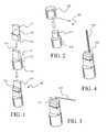
- FIG. 1illustrates a coupler constructed in accordance with present technology in both separated and coupled views thereof
- FIG. 2illustrates an alternate configuration for portions of the two-part coupler in accordance with present technology
- FIG. 3illustrates an alternative embodiment of a two-part coupler including an affixed antenna, in accordance with present technology
- FIG. 4illustrates another alternative embodiment of a two-part coupler including an affixed antenna, in accordance with present technology
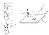
- FIG. 5illustrates a remotely positionable antenna configuration in accordance with present technology, and where the two-part coupler and antenna may be separated by a connecting cable;
- FIG. 6illustrates an exemplary endpoint circuit board incorporating a two-part coupler and antenna configuration in accordance with present disclosure.
- the present subject matteris particularly concerned with antenna and antenna couplers for use with AMR endpoints.
- the present subject matterin certain embodiments thereof corresponds to a low loss antenna coupling mechanism and multiple associated antenna configurations adapted to couple radio frequency (RF) energy from an AMR endpoint to the air.
- RFradio frequency
- a principle of the present technologyis to provided a generic (our “universal”) AMR endpoint module with an internal sealed RF coupler and a selection of snap on antennae of different configurations that may be attached to the outside of the module.
- FIG. 1illustrates a coupler generally 100 constructed in accordance with present technology, and as shown in both separated and coupled views. As may be seen, coupler 100 corresponds to a two-piece construction including a male coupler portion 110 and a female coupler portion 120 .
- Male coupler portion 110may be configured to be associated such as with an AMR endpoint and, in an exemplary embodiment, may be secured by way of lower cylindrical portion 112 to a presently unillustrated printed circuit board (PCB) that itself may support some or all of the electrical components forming the endpoint.
- PCBprinted circuit board
- the lower cylindrical portion 112 of male type coupler portion 110may be soldered to the same PCB supporting the endpoint electronics.
- the lower cylindrical portion 112 of male coupler portion 110may be at least partially encased in any protective plastic or potting material used to protect the endpoint circuitry.
- both coupler componentsmay be encased in protective plastic or potting material.
- male coupler portion 110includes a generally upstanding rectangular portion 114 configured to mate with female coupler portion 120 .
- female coupler portion 120includes an upper portion corresponding generally to a vertical portion of a solid cylinder 122 having a flat surface 124 and a capture portion 126 .
- Capture portion 126is configured as an open rectangular box having sides, one of which corresponds in part to the previously noted flat surface 124 .
- the present exemplary configuration of flat surface 124 and a mating flat surface on the rear (unseen) side of upstanding rectangular portion 114 of male coupler portion 110provide per present subject matter for a low loss coupling of RF signals between the two portions 110 , 120 of coupler 100 .
- capture portion 126 of female coupler portion 120is configured to surround and firmly retain the upstanding rectangular portion 114 of male coupler portion 110 .
- flat surface 124 of solid cylinder portion 122 of female coupler portion 120includes an extended portion 128 that extends slightly above a top portion 116 of upstanding rectangular portion 114 of male coupler portion 110 .
- extended portion 128may itself function as an antenna element in certain instances.
- Alternative antenna configurations, however, in accordance with present technologyare otherwise described herein more particularly with reference to FIGS. 3-5 .
- the male portion 210 of two-part coupler 200corresponds to a dual cylindrical configuration such that an upstanding portion 214 thereof is also configured in a cylindrical arrangement but with a smaller diameter than the supporting lower cylinder portion.
- the female portion of the coupler 220may correspond to a hollowed cap type structure with a hollowed portion 226 configured to securely fit over and surround upstanding portion 214 .
- radio frequency (RF) signalstend to propagate over the surface of a conductor.
- RFradio frequency
- antenna element 330may be attached at one end thereof to the top portion of female coupler portion 322 .
- antenna element 330may be configured with a right-angled bend in relatively close proximity to the point at which such antenna element 330 is secured to the female coupler portion 322 .
- Such right-angled bendmay be provided to accommodate placement of an AMR endpoint incorporating the present remote antenna coupling technology in those instances where the endpoint may be placed in a relatively confining area.
- antenna element 430may be similarly attached to a top portion of female coupler portion 422 but in such embodiment is configured as a straight antenna element.
- antenna elements 330 , 430may correspond to a tuned element corresponding to, for example, a quarter wavelength ( ⁇ /4) antenna element tuned to the operating frequency of the endpoint.
- ⁇ /4quarter wavelength
- antenna elements 330 , 430may correspond to a tuned element corresponding to, for example, a quarter wavelength ( ⁇ /4) antenna element tuned to the operating frequency of the endpoint.
- ⁇ /4quarter wavelength
- an antennamay be chosen to provide signal gain to compensate for losses resulting from a below ground or other signal impeding installation.
- the present subject mattercontemplates a further exemplary configuration where the antenna generally 550 may be located at a distance from the endpoint.
- female coupler portion 522 of the two-part couplermay be connected to antenna 550 by way of a wire 540 .
- Wire 540may correspond to a coaxial cable or other suitable RF conducting cable, as well understood by those of ordinary skill in the art without requiring additional explanation.
- Exemplary antenna 550is preferably configured so as to be selectively mounted at a location to permit effective signal radiation.
- antenna 550may include a support substrate 560 on which are mounted radiating antenna elements 562 , 564 , as well as an optional impedance matching circuit 566 coupled between cable 540 and antenna elements 562 , 564 .
- antenna 550may be encased in whole or in part in a plastic or potting material for environmental protection purposes. It should be appreciated that while FIG. 5 illustrates what appears to be a “bow-tie” type antenna configuration, such is for illustration purposes only and while such an antenna type may be employed such illustration is not intended as a specific limitation of the present technology.
- endpoint circuit board 600includes a supporting substrate corresponding to printed circuit board (PCB) 610 configured to support and interconnect endpoint components including components 612 , 614 and at least the male portion of an exemplary present two-part antenna coupler 616 .
- PCBprinted circuit board
- at least some of the supported componentsform a transmitter circuit to which at least the male portion of the two-part coupler is connected.
- the male portion of two-part antenna coupler 616has been mounted to PCB 610 , an appropriate antenna 630 has been affixed to the female portion of two-part coupler 616 , and both the male and female portions as well as an end portion of antenna 630 have been potted in place by potting material 620 along with the other components 612 , 614 mounted to PCB 610 .
- potting material 620may be provided only covering a portion of the male portion of two-part coupler 616 such that alternate antenna choices may be made following potting of the endpoint.
- exemplary endpoint 600may be incorporated into a meter module.
- meter modulesmay be installed in a pit and may be located as deep as 3 to 4 feet below local surface level.
- endpointsmay be required to transmit at a relatively higher power level just to overcome losses due to their location.
- radio frequency coupling mechanismspreviously employed introduce significant losses on their own. Such losses increase the transmitter power required to overcome the losses, and often at the additional cost of a decrease in battery life.
- the present subject matteraddresses such issues by providing a significant improvement in antenna coupling along with the capability to provide varying levels of antenna gain and location positioning capabilities.
Landscapes
- Details Of Aerials (AREA)
Abstract
Description
Claims (22)
Priority Applications (1)
| Application Number | Priority Date | Filing Date | Title |
|---|---|---|---|
| US12/765,142US8330669B2 (en) | 2010-04-22 | 2010-04-22 | Remote antenna coupling in an AMR device |
Applications Claiming Priority (1)
| Application Number | Priority Date | Filing Date | Title |
|---|---|---|---|
| US12/765,142US8330669B2 (en) | 2010-04-22 | 2010-04-22 | Remote antenna coupling in an AMR device |
Publications (2)
| Publication Number | Publication Date |
|---|---|
| US20110260947A1 US20110260947A1 (en) | 2011-10-27 |
| US8330669B2true US8330669B2 (en) | 2012-12-11 |
Family
ID=44815369
Family Applications (1)
| Application Number | Title | Priority Date | Filing Date |
|---|---|---|---|
| US12/765,142Expired - Fee RelatedUS8330669B2 (en) | 2010-04-22 | 2010-04-22 | Remote antenna coupling in an AMR device |
Country Status (1)
| Country | Link |
|---|---|
| US (1) | US8330669B2 (en) |
Cited By (3)
| Publication number | Priority date | Publication date | Assignee | Title |
|---|---|---|---|---|
| USD718811S1 (en)* | 2013-03-15 | 2014-12-02 | Hans Johann Horn | Mating ring portions for use with binders |
| US9903736B2 (en) | 2014-09-18 | 2018-02-27 | Arad Measuring Technologies Ltd. | Utility meter having a meter register utilizing a multiple resonance antenna |
| US10164320B1 (en) | 2017-08-08 | 2018-12-25 | Badger Meter, Inc. | System and method for sealing potting material from an antenna cavity |
Families Citing this family (3)
| Publication number | Priority date | Publication date | Assignee | Title |
|---|---|---|---|---|
| US8728568B2 (en) | 2012-01-16 | 2014-05-20 | Itron, Inc. | Method for encapsulation of electronics received in water meter pits with an improved wax-based encapsulant/moisture barrier |
| US8481626B1 (en) | 2012-01-16 | 2013-07-09 | Itron, Inc. | Wax-based encapsulant/moisture barrier for use with electronics received in water meter pits |
| US20250118884A1 (en)* | 2023-10-06 | 2025-04-10 | Honeywell International Inc. | Water meter multiband remote antenna rf coupler |
Citations (56)
| Publication number | Priority date | Publication date | Assignee | Title |
|---|---|---|---|---|
| US4387296A (en) | 1979-05-14 | 1983-06-07 | I-Tron, Inc. | Portable utility billing apparatus |
| US4588856A (en) | 1984-08-23 | 1986-05-13 | Timex Computer Corporation | Automatic line impedance balancing circuit for computer/telephone communications interface |
| US4633486A (en) | 1983-07-28 | 1986-12-30 | Cyclotomics, Inc. | Method and apparatus for synchronization by coherent reinforcement |
| US4654662A (en) | 1984-07-23 | 1987-03-31 | James Van Orsdel | Apparatus for telemetry apparatus for reading utility meters |
| US4737797A (en) | 1986-06-26 | 1988-04-12 | Motorola, Inc. | Microstrip balun-antenna apparatus |
| US4744004A (en) | 1987-05-27 | 1988-05-10 | Transdata, Inc. | Electricity meter with solid-state circuits |
| US4780910A (en) | 1984-12-12 | 1988-10-25 | Scientific-Atlanta, Inc. | Display for a remote receiver in an electrical utility load management system |
| US4800393A (en) | 1987-08-03 | 1989-01-24 | General Electric Company | Microstrip fed printed dipole with an integral balun and 180 degree phase shift bit |
| US4804957A (en) | 1985-11-27 | 1989-02-14 | Triad Communications, Inc. | Utility meter and submetering system |
| US4825220A (en) | 1986-11-26 | 1989-04-25 | General Electric Company | Microstrip fed printed dipole with an integral balun |
| US4904995A (en) | 1986-01-21 | 1990-02-27 | Emerson Electric Co. | Integrated remote electricity meter transponder and combination |
| US4924236A (en) | 1987-11-03 | 1990-05-08 | Raytheon Company | Patch radiator element with microstrip balian circuit providing double-tuned impedance matching |
| US5010568A (en) | 1989-04-04 | 1991-04-23 | Sparton Corporation | Remote meter reading method and apparatus |
| US5014213A (en) | 1988-04-20 | 1991-05-07 | Domestic Automation Company, Inc. | System for use with polyphase utility meters for recording time of energy use |
| US5111407A (en) | 1989-08-25 | 1992-05-05 | Arad Ltd. | System for measuring and recording a utility consumption |
| US5270639A (en) | 1989-09-22 | 1993-12-14 | Landis & Gyr Metering, Inc. | Time of use register for use with a utility meter |
| US5448230A (en) | 1993-06-25 | 1995-09-05 | Metscan, Incorporated | Remote data acquisition and communication system |
| US5486755A (en) | 1994-12-27 | 1996-01-23 | General Electric Company | Electronic meter having anti-tampering magnetic shield |
| JPH08126085A (en) | 1994-10-26 | 1996-05-17 | Victor Co Of Japan Ltd | Wireless microphone incorporating antenna |
| US5519387A (en) | 1994-04-14 | 1996-05-21 | Motorola, Inc. | Utility meter assembly and remote module and mounting apparatus and assembly |
| US5541589A (en) | 1994-12-15 | 1996-07-30 | Delaney; Patrick J. | Power meter data acquisition and control system |
| US5553094A (en) | 1990-02-15 | 1996-09-03 | Iris Systems, Inc. | Radio communication network for remote data generating stations |
| WO1996039753A1 (en) | 1995-06-06 | 1996-12-12 | Telefonaktiebolaget Lm Ericsson (Publ) | Electronic metering equipment system |
| CN2247819Y (en) | 1995-12-01 | 1997-02-19 | 同济大学 | Cluster type electric civil electric energy meter |
| US5617084A (en) | 1993-09-10 | 1997-04-01 | Sears; Lawrence M. | Apparatus for communicating utility usage-related information from a utility usage location to a utility usage registering device |
| US5659300A (en) | 1995-01-30 | 1997-08-19 | Innovatec Corporation | Meter for measuring volumetric consumption of a commodity |
| US5678201A (en) | 1996-02-01 | 1997-10-14 | Motorola, Inc. | Antenna assembly with balun and tuning element for a portable radio |
| CN1163404A (en) | 1996-04-19 | 1997-10-29 | 黄金富 | Controlled electric power metering system and device |
| US5708446A (en) | 1995-04-29 | 1998-01-13 | Qualcomm Incorporated | Printed circuit antenna array using corner reflector |
| US5711675A (en) | 1993-03-17 | 1998-01-27 | Yasaki Corporation | Meter module, connecting device thereof, wiring harness protector, and connecting device of instrument wiring harness |
| US5719564A (en) | 1996-05-10 | 1998-02-17 | Sears; Lawrence M. | Utility meter reading system |
| WO1998010299A1 (en) | 1996-09-06 | 1998-03-12 | Innovatec Corporation | Electronic electric meter for networked meter reading |
| US5801643A (en) | 1996-06-20 | 1998-09-01 | Northrop Grumman Corporation | Remote utility meter reading system |
| US5808558A (en) | 1994-09-29 | 1998-09-15 | Kemp Meek Manufacturing, Inc. | Remote universal send/receive utility usage data gathering system |
| US5826195A (en) | 1992-01-27 | 1998-10-20 | Highwaymaster Communications, Inc. | Data messaging in a communications network |
| US5847683A (en) | 1996-10-28 | 1998-12-08 | Motorola, Inc. | Transmission line antenna and utility meter using same |
| US5892758A (en) | 1996-07-11 | 1999-04-06 | Qualcomm Incorporated | Concentrated subscriber wireless remote telemetry system |
| US5896097A (en) | 1996-03-06 | 1999-04-20 | Schlumberger Resource Management Services, Inc. | System for utility meter communications using a single RF frequency |
| US5909640A (en) | 1995-01-20 | 1999-06-01 | Whisper Communications, Inc. | Wireless communication system for adapting to frequency drift |
| US5966010A (en) | 1998-02-09 | 1999-10-12 | Abb Power T&D Company Inc. | Electrical energy meter with snap fit interlocking parts |
| US5986574A (en) | 1997-10-16 | 1999-11-16 | Peco Energy Company | System and method for communication between remote locations |
| US5995593A (en) | 1996-04-30 | 1999-11-30 | Samsung Electronics Co., Ltd. | Wire/wireless communication system for communicating between two locations using telephone network |
| US6014089A (en) | 1996-10-28 | 2000-01-11 | Tracy Corporation Ii | Method for transmitting data using a digital control channel of a wireless network |
| US6067052A (en) | 1998-09-18 | 2000-05-23 | Lucent Technologies Inc. | Loop antenna configuration for printed wire board applications |
| US6069571A (en) | 1995-10-06 | 2000-05-30 | Motorola, Inc. | Apparatus and method for collecting meter data |
| US6078785A (en) | 1996-10-15 | 2000-06-20 | Bush; E. William | Demand reporting of electricity consumption by radio in relays to a base station, and demand relays wattmeters so reporting over a wide area |
| US6150955A (en) | 1996-10-28 | 2000-11-21 | Tracy Corporation Ii | Apparatus and method for transmitting data via a digital control channel of a digital wireless network |
| US6208266B1 (en) | 1995-08-23 | 2001-03-27 | Scientific Telemetry Corporation | Remote data acquisition and processing system |
| US6222503B1 (en) | 1997-01-10 | 2001-04-24 | William Gietema | System and method of integrating and concealing antennas, antenna subsystems and communications subsystems |
| US6246677B1 (en) | 1996-09-06 | 2001-06-12 | Innovatec Communications, Llc | Automatic meter reading data communication system |
| US6300907B1 (en) | 2000-01-25 | 2001-10-09 | Badger Meter, Inc. | Antenna assembly for subsurface meter pits |
| US6411219B1 (en) | 1999-12-29 | 2002-06-25 | Siemens Power Transmission And Distribution, Inc. | Adaptive radio communication for a utility meter |
| US6650249B2 (en) | 1998-05-01 | 2003-11-18 | Elster Electricity, Llc | Wireless area network communications module for utility meters |
| WO2005094154A2 (en) | 2004-03-31 | 2005-10-13 | Kamstrup A/S | Method and device for detecting an external antenna |
| US7446672B2 (en)* | 2005-03-24 | 2008-11-04 | M&Fc Holding, Llc | Method and apparatus for coupling a meter register to an automatic meter reading communication device |
| US20100110617A1 (en)* | 2001-11-26 | 2010-05-06 | Itron, Inc. | Embedded antenna apparatus for utility metering applications |
- 2010
- 2010-04-22USUS12/765,142patent/US8330669B2/ennot_activeExpired - Fee Related
Patent Citations (58)
| Publication number | Priority date | Publication date | Assignee | Title |
|---|---|---|---|---|
| US4387296A (en) | 1979-05-14 | 1983-06-07 | I-Tron, Inc. | Portable utility billing apparatus |
| US4633486A (en) | 1983-07-28 | 1986-12-30 | Cyclotomics, Inc. | Method and apparatus for synchronization by coherent reinforcement |
| US4654662A (en) | 1984-07-23 | 1987-03-31 | James Van Orsdel | Apparatus for telemetry apparatus for reading utility meters |
| US4588856A (en) | 1984-08-23 | 1986-05-13 | Timex Computer Corporation | Automatic line impedance balancing circuit for computer/telephone communications interface |
| US4780910A (en) | 1984-12-12 | 1988-10-25 | Scientific-Atlanta, Inc. | Display for a remote receiver in an electrical utility load management system |
| US4804957A (en) | 1985-11-27 | 1989-02-14 | Triad Communications, Inc. | Utility meter and submetering system |
| US4904995A (en) | 1986-01-21 | 1990-02-27 | Emerson Electric Co. | Integrated remote electricity meter transponder and combination |
| US4737797A (en) | 1986-06-26 | 1988-04-12 | Motorola, Inc. | Microstrip balun-antenna apparatus |
| US4825220A (en) | 1986-11-26 | 1989-04-25 | General Electric Company | Microstrip fed printed dipole with an integral balun |
| US4744004A (en) | 1987-05-27 | 1988-05-10 | Transdata, Inc. | Electricity meter with solid-state circuits |
| US4800393A (en) | 1987-08-03 | 1989-01-24 | General Electric Company | Microstrip fed printed dipole with an integral balun and 180 degree phase shift bit |
| US4924236A (en) | 1987-11-03 | 1990-05-08 | Raytheon Company | Patch radiator element with microstrip balian circuit providing double-tuned impedance matching |
| US5014213A (en) | 1988-04-20 | 1991-05-07 | Domestic Automation Company, Inc. | System for use with polyphase utility meters for recording time of energy use |
| US5010568A (en) | 1989-04-04 | 1991-04-23 | Sparton Corporation | Remote meter reading method and apparatus |
| US5111407A (en) | 1989-08-25 | 1992-05-05 | Arad Ltd. | System for measuring and recording a utility consumption |
| US5270639A (en) | 1989-09-22 | 1993-12-14 | Landis & Gyr Metering, Inc. | Time of use register for use with a utility meter |
| US5553094A (en) | 1990-02-15 | 1996-09-03 | Iris Systems, Inc. | Radio communication network for remote data generating stations |
| US5826195A (en) | 1992-01-27 | 1998-10-20 | Highwaymaster Communications, Inc. | Data messaging in a communications network |
| US6016432A (en) | 1993-03-04 | 2000-01-18 | Telefonaktiebolaget L/M Ericsson (Publ) | Electronic metering equipment system |
| US5711675A (en) | 1993-03-17 | 1998-01-27 | Yasaki Corporation | Meter module, connecting device thereof, wiring harness protector, and connecting device of instrument wiring harness |
| US5448230A (en) | 1993-06-25 | 1995-09-05 | Metscan, Incorporated | Remote data acquisition and communication system |
| US5617084A (en) | 1993-09-10 | 1997-04-01 | Sears; Lawrence M. | Apparatus for communicating utility usage-related information from a utility usage location to a utility usage registering device |
| US5519387A (en) | 1994-04-14 | 1996-05-21 | Motorola, Inc. | Utility meter assembly and remote module and mounting apparatus and assembly |
| US5808558A (en) | 1994-09-29 | 1998-09-15 | Kemp Meek Manufacturing, Inc. | Remote universal send/receive utility usage data gathering system |
| JPH08126085A (en) | 1994-10-26 | 1996-05-17 | Victor Co Of Japan Ltd | Wireless microphone incorporating antenna |
| US5541589A (en) | 1994-12-15 | 1996-07-30 | Delaney; Patrick J. | Power meter data acquisition and control system |
| US5486755A (en) | 1994-12-27 | 1996-01-23 | General Electric Company | Electronic meter having anti-tampering magnetic shield |
| US5909640A (en) | 1995-01-20 | 1999-06-01 | Whisper Communications, Inc. | Wireless communication system for adapting to frequency drift |
| US5659300A (en) | 1995-01-30 | 1997-08-19 | Innovatec Corporation | Meter for measuring volumetric consumption of a commodity |
| US5708446A (en) | 1995-04-29 | 1998-01-13 | Qualcomm Incorporated | Printed circuit antenna array using corner reflector |
| WO1996039753A1 (en) | 1995-06-06 | 1996-12-12 | Telefonaktiebolaget Lm Ericsson (Publ) | Electronic metering equipment system |
| US6208266B1 (en) | 1995-08-23 | 2001-03-27 | Scientific Telemetry Corporation | Remote data acquisition and processing system |
| US6069571A (en) | 1995-10-06 | 2000-05-30 | Motorola, Inc. | Apparatus and method for collecting meter data |
| CN2247819Y (en) | 1995-12-01 | 1997-02-19 | 同济大学 | Cluster type electric civil electric energy meter |
| US5678201A (en) | 1996-02-01 | 1997-10-14 | Motorola, Inc. | Antenna assembly with balun and tuning element for a portable radio |
| US5896097A (en) | 1996-03-06 | 1999-04-20 | Schlumberger Resource Management Services, Inc. | System for utility meter communications using a single RF frequency |
| US5914673A (en) | 1996-03-06 | 1999-06-22 | Schlumberger | System for utility meter communications using a single RF frequency |
| CN1163404A (en) | 1996-04-19 | 1997-10-29 | 黄金富 | Controlled electric power metering system and device |
| US5995593A (en) | 1996-04-30 | 1999-11-30 | Samsung Electronics Co., Ltd. | Wire/wireless communication system for communicating between two locations using telephone network |
| US5719564A (en) | 1996-05-10 | 1998-02-17 | Sears; Lawrence M. | Utility meter reading system |
| US5801643A (en) | 1996-06-20 | 1998-09-01 | Northrop Grumman Corporation | Remote utility meter reading system |
| US5892758A (en) | 1996-07-11 | 1999-04-06 | Qualcomm Incorporated | Concentrated subscriber wireless remote telemetry system |
| US6246677B1 (en) | 1996-09-06 | 2001-06-12 | Innovatec Communications, Llc | Automatic meter reading data communication system |
| WO1998010299A1 (en) | 1996-09-06 | 1998-03-12 | Innovatec Corporation | Electronic electric meter for networked meter reading |
| US6078785A (en) | 1996-10-15 | 2000-06-20 | Bush; E. William | Demand reporting of electricity consumption by radio in relays to a base station, and demand relays wattmeters so reporting over a wide area |
| US5847683A (en) | 1996-10-28 | 1998-12-08 | Motorola, Inc. | Transmission line antenna and utility meter using same |
| US6014089A (en) | 1996-10-28 | 2000-01-11 | Tracy Corporation Ii | Method for transmitting data using a digital control channel of a wireless network |
| US6150955A (en) | 1996-10-28 | 2000-11-21 | Tracy Corporation Ii | Apparatus and method for transmitting data via a digital control channel of a digital wireless network |
| US6222503B1 (en) | 1997-01-10 | 2001-04-24 | William Gietema | System and method of integrating and concealing antennas, antenna subsystems and communications subsystems |
| US5986574A (en) | 1997-10-16 | 1999-11-16 | Peco Energy Company | System and method for communication between remote locations |
| US5966010A (en) | 1998-02-09 | 1999-10-12 | Abb Power T&D Company Inc. | Electrical energy meter with snap fit interlocking parts |
| US6650249B2 (en) | 1998-05-01 | 2003-11-18 | Elster Electricity, Llc | Wireless area network communications module for utility meters |
| US6067052A (en) | 1998-09-18 | 2000-05-23 | Lucent Technologies Inc. | Loop antenna configuration for printed wire board applications |
| US6411219B1 (en) | 1999-12-29 | 2002-06-25 | Siemens Power Transmission And Distribution, Inc. | Adaptive radio communication for a utility meter |
| US6300907B1 (en) | 2000-01-25 | 2001-10-09 | Badger Meter, Inc. | Antenna assembly for subsurface meter pits |
| US20100110617A1 (en)* | 2001-11-26 | 2010-05-06 | Itron, Inc. | Embedded antenna apparatus for utility metering applications |
| WO2005094154A2 (en) | 2004-03-31 | 2005-10-13 | Kamstrup A/S | Method and device for detecting an external antenna |
| US7446672B2 (en)* | 2005-03-24 | 2008-11-04 | M&Fc Holding, Llc | Method and apparatus for coupling a meter register to an automatic meter reading communication device |
Non-Patent Citations (5)
| Title |
|---|
| Automated translation of Abstract of CN 1163404. |
| Automated translation of Abstract of CN 2247819. |
| Automated translation of Abstract of JP 8126085. |
| Ron A. Haberkorn and Paul E. Nikolich, "Driving Forces in Wireless Data Communications," pp. 39-47, 1Q1996, New Telecom Quarterly, Technology Futures, Inc. |
| Simon Guy and Simon Marvin, "Pathways to 'Smarter' Utility Meters: the Socio-technical Shaping of New Metering Technologies," pp. 1-41, Nov. 1995, School of Architecture, Planning & Landscape, Global Urban Research Unit, Centre for Urban Technology, University of Newcastle upon Tyne. |
Cited By (5)
| Publication number | Priority date | Publication date | Assignee | Title |
|---|---|---|---|---|
| USD718811S1 (en)* | 2013-03-15 | 2014-12-02 | Hans Johann Horn | Mating ring portions for use with binders |
| US10086639B2 (en) | 2013-03-15 | 2018-10-02 | Hans Johann Horn | Binder apparatus |
| US10562336B2 (en) | 2013-03-15 | 2020-02-18 | Hans Johann Horn | Binder apparatus |
| US9903736B2 (en) | 2014-09-18 | 2018-02-27 | Arad Measuring Technologies Ltd. | Utility meter having a meter register utilizing a multiple resonance antenna |
| US10164320B1 (en) | 2017-08-08 | 2018-12-25 | Badger Meter, Inc. | System and method for sealing potting material from an antenna cavity |
Also Published As
| Publication number | Publication date |
|---|---|
| US20110260947A1 (en) | 2011-10-27 |
Similar Documents
| Publication | Publication Date | Title |
|---|---|---|
| US8330669B2 (en) | Remote antenna coupling in an AMR device | |
| US7365687B2 (en) | Antenna with disk radiator used in automatic meter reading (AMR) device | |
| US6177883B1 (en) | Utility meter transponder exposed ground level antenna assembly | |
| US8228209B2 (en) | Smart meter cover with integral untethered antenna elements for AMI communications | |
| US20100026515A1 (en) | Utility Metering System With Compact And Robust Antenna For Subsurface Installation | |
| US20050285807A1 (en) | RF communication device and method of using it and antenna construction for use in the device and method | |
| US20160305807A1 (en) | Consumption Meter Comprising A Foldable Printed Circuit Board Assembly | |
| US9601831B2 (en) | Radio device | |
| CA2847471A1 (en) | Capacitive rf coupler for utility smart meter radio frequency communications | |
| JP2015129647A (en) | Remote meter-reading device | |
| US7639203B2 (en) | Spiral coil loaded short wire antenna | |
| WO2006031722A3 (en) | Wireless fluid level measuring system | |
| EP2833476B1 (en) | Flow volume measuring apparatus | |
| US10243264B2 (en) | Pit lid trident antenna arrangement | |
| KR20170128673A (en) | Shorted Patch Antenna | |
| US20100328910A1 (en) | Automation appliance | |
| US20090243935A1 (en) | Plane super wide band coupling antenna | |
| US8159401B2 (en) | Antenna for sealed transmitter assembly in subsurface utility installations | |
| US8269689B2 (en) | Antenna device | |
| EP3931905B1 (en) | Antenna for soil sensors | |
| CN104364963A (en) | Wireless device | |
| US11901604B2 (en) | Antenna for facilitating remote reading of utility meters | |
| KR101188779B1 (en) | Antena devices for monitoring and diagnosis apparatus of power transmission line | |
| ES2834088T3 (en) | Antenna apparatus using a utility line and procedures for its manufacture and use | |
| KR100887373B1 (en) | Patch antenna device |
Legal Events
| Date | Code | Title | Description |
|---|---|---|---|
| AS | Assignment | Owner name:ITRON, INC., WASHINGTON Free format text:ASSIGNMENT OF ASSIGNORS INTEREST;ASSIGNORS:CORNWALL, MARK K.;LIN, JUNSONG;REEL/FRAME:024310/0375 Effective date:20100427 | |
| AS | Assignment | Owner name:WELLS FARGO BANK, NATIONAL ASSOCIATION, WASHINGTON Free format text:SECURITY AGREEMENT;ASSIGNOR:ITRON, INC.;REEL/FRAME:026761/0069 Effective date:20110805 | |
| STCF | Information on status: patent grant | Free format text:PATENTED CASE | |
| FPAY | Fee payment | Year of fee payment:4 | |
| AS | Assignment | Owner name:WELLS FARGO BANK, NATIONAL ASSOCIATION, NORTH CAROLINA Free format text:SECURITY INTEREST;ASSIGNORS:ITRON, INC.;ITRON NETWORKED SOLUTIONS, INC.;REEL/FRAME:045017/0893 Effective date:20180105 Owner name:WELLS FARGO BANK, NATIONAL ASSOCIATION, NORTH CARO Free format text:SECURITY INTEREST;ASSIGNORS:ITRON, INC.;ITRON NETWORKED SOLUTIONS, INC.;REEL/FRAME:045017/0893 Effective date:20180105 | |
| FEPP | Fee payment procedure | Free format text:MAINTENANCE FEE REMINDER MAILED (ORIGINAL EVENT CODE: REM.); ENTITY STATUS OF PATENT OWNER: LARGE ENTITY | |
| LAPS | Lapse for failure to pay maintenance fees | Free format text:PATENT EXPIRED FOR FAILURE TO PAY MAINTENANCE FEES (ORIGINAL EVENT CODE: EXP.); ENTITY STATUS OF PATENT OWNER: LARGE ENTITY | |
| STCH | Information on status: patent discontinuation | Free format text:PATENT EXPIRED DUE TO NONPAYMENT OF MAINTENANCE FEES UNDER 37 CFR 1.362 | |
| FP | Lapsed due to failure to pay maintenance fee | Effective date:20201211 |