US8330569B2 - System and method for receiving data for training a trainable transmitter - Google Patents
System and method for receiving data for training a trainable transmitterDownload PDFInfo
- Publication number
- US8330569B2 US8330569B2US10/558,121US55812104AUS8330569B2US 8330569 B2US8330569 B2US 8330569B2US 55812104 AUS55812104 AUS 55812104AUS 8330569 B2US8330569 B2US 8330569B2
- Authority
- US
- United States
- Prior art keywords
- transmitter
- control
- data
- remote
- control circuit
- Prior art date
- Legal status (The legal status is an assumption and is not a legal conclusion. Google has not performed a legal analysis and makes no representation as to the accuracy of the status listed.)
- Active, expires
Links
Images


Classifications
- B—PERFORMING OPERATIONS; TRANSPORTING
- B60—VEHICLES IN GENERAL
- B60R—VEHICLES, VEHICLE FITTINGS, OR VEHICLE PARTS, NOT OTHERWISE PROVIDED FOR
- B60R25/00—Fittings or systems for preventing or indicating unauthorised use or theft of vehicles
- B60R25/20—Means to switch the anti-theft system on or off
- B60R25/24—Means to switch the anti-theft system on or off using electronic identifiers containing a code not memorised by the user
- G—PHYSICS
- G07—CHECKING-DEVICES
- G07C—TIME OR ATTENDANCE REGISTERS; REGISTERING OR INDICATING THE WORKING OF MACHINES; GENERATING RANDOM NUMBERS; VOTING OR LOTTERY APPARATUS; ARRANGEMENTS, SYSTEMS OR APPARATUS FOR CHECKING NOT PROVIDED FOR ELSEWHERE
- G07C9/00—Individual registration on entry or exit
- G07C9/00174—Electronically operated locks; Circuits therefor; Nonmechanical keys therefor, e.g. passive or active electrical keys or other data carriers without mechanical keys
- G07C9/00857—Electronically operated locks; Circuits therefor; Nonmechanical keys therefor, e.g. passive or active electrical keys or other data carriers without mechanical keys where the code of the data carrier can be programmed
- G—PHYSICS
- G08—SIGNALLING
- G08C—TRANSMISSION SYSTEMS FOR MEASURED VALUES, CONTROL OR SIMILAR SIGNALS
- G08C17/00—Arrangements for transmitting signals characterised by the use of a wireless electrical link
- G08C17/02—Arrangements for transmitting signals characterised by the use of a wireless electrical link using a radio link
- G—PHYSICS
- G08—SIGNALLING
- G08C—TRANSMISSION SYSTEMS FOR MEASURED VALUES, CONTROL OR SIMILAR SIGNALS
- G08C19/00—Electric signal transmission systems
- G08C19/16—Electric signal transmission systems in which transmission is by pulses
- G08C19/28—Electric signal transmission systems in which transmission is by pulses using pulse code
- H—ELECTRICITY
- H04—ELECTRIC COMMUNICATION TECHNIQUE
- H04B—TRANSMISSION
- H04B5/00—Near-field transmission systems, e.g. inductive or capacitive transmission systems
- H04B5/20—Near-field transmission systems, e.g. inductive or capacitive transmission systems characterised by the transmission technique; characterised by the transmission medium
- H04B5/22—Capacitive coupling
- G—PHYSICS
- G07—CHECKING-DEVICES
- G07C—TIME OR ATTENDANCE REGISTERS; REGISTERING OR INDICATING THE WORKING OF MACHINES; GENERATING RANDOM NUMBERS; VOTING OR LOTTERY APPARATUS; ARRANGEMENTS, SYSTEMS OR APPARATUS FOR CHECKING NOT PROVIDED FOR ELSEWHERE
- G07C9/00—Individual registration on entry or exit
- G07C9/00174—Electronically operated locks; Circuits therefor; Nonmechanical keys therefor, e.g. passive or active electrical keys or other data carriers without mechanical keys
- G07C9/00182—Electronically operated locks; Circuits therefor; Nonmechanical keys therefor, e.g. passive or active electrical keys or other data carriers without mechanical keys operated with unidirectional data transmission between data carrier and locks
- G07C2009/0019—Electronically operated locks; Circuits therefor; Nonmechanical keys therefor, e.g. passive or active electrical keys or other data carriers without mechanical keys operated with unidirectional data transmission between data carrier and locks the keyless data carrier having only one limited data transmission rangs
- G—PHYSICS
- G07—CHECKING-DEVICES
- G07C—TIME OR ATTENDANCE REGISTERS; REGISTERING OR INDICATING THE WORKING OF MACHINES; GENERATING RANDOM NUMBERS; VOTING OR LOTTERY APPARATUS; ARRANGEMENTS, SYSTEMS OR APPARATUS FOR CHECKING NOT PROVIDED FOR ELSEWHERE
- G07C9/00—Individual registration on entry or exit
- G07C9/00174—Electronically operated locks; Circuits therefor; Nonmechanical keys therefor, e.g. passive or active electrical keys or other data carriers without mechanical keys
- G07C2009/00753—Electronically operated locks; Circuits therefor; Nonmechanical keys therefor, e.g. passive or active electrical keys or other data carriers without mechanical keys operated by active electrical keys
- G07C2009/00769—Electronically operated locks; Circuits therefor; Nonmechanical keys therefor, e.g. passive or active electrical keys or other data carriers without mechanical keys operated by active electrical keys with data transmission performed by wireless means
- G07C2009/00793—Electronically operated locks; Circuits therefor; Nonmechanical keys therefor, e.g. passive or active electrical keys or other data carriers without mechanical keys operated by active electrical keys with data transmission performed by wireless means by Hertzian waves
- G—PHYSICS
- G07—CHECKING-DEVICES
- G07C—TIME OR ATTENDANCE REGISTERS; REGISTERING OR INDICATING THE WORKING OF MACHINES; GENERATING RANDOM NUMBERS; VOTING OR LOTTERY APPARATUS; ARRANGEMENTS, SYSTEMS OR APPARATUS FOR CHECKING NOT PROVIDED FOR ELSEWHERE
- G07C9/00—Individual registration on entry or exit
- G07C9/00174—Electronically operated locks; Circuits therefor; Nonmechanical keys therefor, e.g. passive or active electrical keys or other data carriers without mechanical keys
- G07C9/00857—Electronically operated locks; Circuits therefor; Nonmechanical keys therefor, e.g. passive or active electrical keys or other data carriers without mechanical keys where the code of the data carrier can be programmed
- G07C2009/00865—Electronically operated locks; Circuits therefor; Nonmechanical keys therefor, e.g. passive or active electrical keys or other data carriers without mechanical keys where the code of the data carrier can be programmed remotely by wireless communication
- G—PHYSICS
- G07—CHECKING-DEVICES
- G07C—TIME OR ATTENDANCE REGISTERS; REGISTERING OR INDICATING THE WORKING OF MACHINES; GENERATING RANDOM NUMBERS; VOTING OR LOTTERY APPARATUS; ARRANGEMENTS, SYSTEMS OR APPARATUS FOR CHECKING NOT PROVIDED FOR ELSEWHERE
- G07C9/00—Individual registration on entry or exit
- G07C9/00174—Electronically operated locks; Circuits therefor; Nonmechanical keys therefor, e.g. passive or active electrical keys or other data carriers without mechanical keys
- G07C9/00857—Electronically operated locks; Circuits therefor; Nonmechanical keys therefor, e.g. passive or active electrical keys or other data carriers without mechanical keys where the code of the data carrier can be programmed
- G07C2009/00888—Electronically operated locks; Circuits therefor; Nonmechanical keys therefor, e.g. passive or active electrical keys or other data carriers without mechanical keys where the code of the data carrier can be programmed programming by learning
- G—PHYSICS
- G07—CHECKING-DEVICES
- G07C—TIME OR ATTENDANCE REGISTERS; REGISTERING OR INDICATING THE WORKING OF MACHINES; GENERATING RANDOM NUMBERS; VOTING OR LOTTERY APPARATUS; ARRANGEMENTS, SYSTEMS OR APPARATUS FOR CHECKING NOT PROVIDED FOR ELSEWHERE
- G07C9/00—Individual registration on entry or exit
- G07C9/00174—Electronically operated locks; Circuits therefor; Nonmechanical keys therefor, e.g. passive or active electrical keys or other data carriers without mechanical keys
- G07C9/00896—Electronically operated locks; Circuits therefor; Nonmechanical keys therefor, e.g. passive or active electrical keys or other data carriers without mechanical keys specially adapted for particular uses
- G07C2009/00928—Electronically operated locks; Circuits therefor; Nonmechanical keys therefor, e.g. passive or active electrical keys or other data carriers without mechanical keys specially adapted for particular uses for garage doors
- G—PHYSICS
- G07—CHECKING-DEVICES
- G07C—TIME OR ATTENDANCE REGISTERS; REGISTERING OR INDICATING THE WORKING OF MACHINES; GENERATING RANDOM NUMBERS; VOTING OR LOTTERY APPARATUS; ARRANGEMENTS, SYSTEMS OR APPARATUS FOR CHECKING NOT PROVIDED FOR ELSEWHERE
- G07C9/00—Individual registration on entry or exit
- G07C9/00174—Electronically operated locks; Circuits therefor; Nonmechanical keys therefor, e.g. passive or active electrical keys or other data carriers without mechanical keys
- G07C9/00182—Electronically operated locks; Circuits therefor; Nonmechanical keys therefor, e.g. passive or active electrical keys or other data carriers without mechanical keys operated with unidirectional data transmission between data carrier and locks
- G—PHYSICS
- G08—SIGNALLING
- G08C—TRANSMISSION SYSTEMS FOR MEASURED VALUES, CONTROL OR SIMILAR SIGNALS
- G08C2201/00—Transmission systems of control signals via wireless link
- G08C2201/20—Binding and programming of remote control devices
Definitions
- the present inventionrelates to a trainable radio frequency (RF) transmitter and particularly to a trainable transmitter for a vehicle that transmits a control signal to a remotely controlled device.
- RFradio frequency
- Electronically operated remote control systemssuch as garage door openers, home security systems, home lighting systems, etc. are becoming increasingly common.
- Such electronic remote control systemstypically employ a battery powered portable RF transmitter for transmitting a modulated and encoded RF signal to a receiver located at the remote control system.
- a garage door opener systemmay include a receiver located within the homeowner's garage. The garage door receiver is tuned to the frequency of its associated portable RF transmitter and demodulates a predetermined code programmed into both the portable transmitter and receiver for operating the garage door.
- Conventional portable transmittershave consisted of a portable housing which typically is clipped to a vehicle's visor or otherwise loosely stored in the vehicle.
- a trainable transceivermay be provided in vehicles for use with remote control devices such as garage door openers, gate controllers, alarm controls, home lighting systems, etc.
- a trainable transceivermay learn and store the modulation scheme (i.e., code format), transmission codes and the particular RF carrier frequencies of one or more OEM (original equipment manufacturer) remote transmitters for use with the remote control devices.
- a vehicle ownermay train the transceiver to the vehicle owner's existing remote RF transmitter. Subsequently, the old remote RF transmitter can be discarded and stored.
- a trainable transceiverincludes receiver circuitry to receive a control signal from a remote transmitter during a training process.
- trainable transmittershave been developed that have the capability of recognizing when a received signal has been originated from a transmitter that generates a code that varies with each transmission in accordance with a cryptographic algorithm. When such a variable code is recognized, the trainable transmitter determines which cryptographic algorithm is used to generate and transmit the next code to which the receiver will respond.
- a system for receiving data for training a trainable transmitter used to subsequently transmit a modulated RF signal having the received dataincludes an antenna, a capacitive detection circuit coupled to the antenna and configured to detect data provided in a control signal of a remote control transmitter used to remotely actuate a device and a control circuit coupled to the capacitive detection circuit and configured to store the received data and generate the RF signal having the received data to be transmitted by the trainable transmitter to actuate the device.
- a method for training a trainable transmitter on a vehicle used to subsequently transmit a modulated RF signal having characteristics of a control signal used to remotely actuate a remote electronic systemincludes initiating a training sequence and activating a remote transmitter associated with the remote electronic system to provide the control signal.
- the methodalso includes capacitively detecting data of the control signal transmitted by the remote transmitter. Once the data is detected, it is stored in a memory.
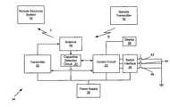
- FIG. 1shows a remote control system and a vehicle having a trainable transmitter in accordance with an embodiment.
- FIG. 2is a schematic block diagram of a trainable transmitter system in accordance with an embodiment.
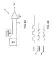
- FIG. 3is an exemplary circuit diagram for a remote transmitter for an electronic system in accordance with an embodiment.
- FIG. 4Ais a circuit diagram of a capacitive detection circuit in accordance with an embodiment.
- FIG. 4Bshows an exemplary set of waveforms for the capacitive detection circuit of FIG. 4A in accordance with an embodiment.
- FIG. 5illustrates a method for training a trainable transmitter in accordance with an embodiment.
- FIG. 1shows a remote control system and a vehicle having a trainable transmitter in accordance with an embodiment.
- Vehicle 10is an automobile, although it should be understood that the trainable transmitter of the present invention may be embodied in other vehicles or other systems such as a portable housing.
- the system as illustrated in FIG. 1also includes a portable remote transmitter 12 for a remote electronic system 14 .
- Remote transmitter 12may be in the form of, for example, a remote controller.
- Remote electronic system or device 14may be an electronic system such as a garage door opener, home security system, home lighting system, electronically operated access gates, or any other household appliance or system capable of receiving an RF control signal, etc.
- a trainable transmitter 34(see, FIG. 2 ) is included in a control module which may be mounted within the vehicle 10 inside, for example, a rearview mirror 16 or other suitable location such as an overhead console, a visor, a dashboard, etc.
- the trainable transmitter (not shown) in vehicle 10may be trained using remote transmitter 12 which is used to control remote electronic system 14 .
- Coded radio frequency (RF) (or infrared) energy (or control signal) of remote transmitter 12is transmitted as indicated by arrow A to the trainable transmitter 34 (see FIG. 2 ) of the control module mounted to, for example, rearview mirror 16 .
- the trainable transmitter (not shown)receives the encoded control signal, demodulates it and a programmable control circuit of the transmitter learns the control code (e.g., fixed or rolling code) and determines a carrier frequency for the signal and stores this information for later transmission.
- control codee.g., fixed or rolling code
- the trainable transmittermay then be used to selectively generate and transmit an RF control signal with the frequency and learned control code as indicated by arrow T to remote electrical system 14 , such as, for example, a garage door opening mechanism, that is responsive to the control signal.
- the programmable control circuitcontrols a transmitter to generate a carrier signal and modulate the control code (e.g., fixed or rolling code) onto a carrier signal to generate a control signal.
- control codee.g., fixed or rolling code
- FIG. 2is a schematic block diagram of a trainable transmitter 34 in accordance with an embodiment.
- Trainable transmitter 34 shown in FIG. 2includes a transmitter circuit 20 that is coupled to an antenna 28 and a control circuit 22 .
- Control circuit 22is configured to control the various portions of trainable transmitter 34 , to store data in memory, to operate preprogrammed functionality, etc.
- Control circuit 22may include various types of control circuitry, digital and/or analog, and may include a microprocessor, microcontroller, application specific integrated circuit (ASIC), or other digital and/or analog circuitry configured to perform various input/output, control, analysis, and other functions to be described herein.
- ASICapplication specific integrated circuit
- Control circuit 22is coupled to an operator input device which may include one or more push button switches 42 , 44 , 46 , but may alternatively include other user input devices such as, switches, knobs, dials, etc., or even a voice-actuated input control circuit configured to receive voice signals from a vehicle occupant and to provide such signals to control circuit 22 for control of trainable transmitter 34 .
- a switch interface 24is connected to one terminal of each of the three push button switches 42 , 44 and 46 , which have their remaining terminal connected to ground.
- Switches 42 , 44 and 46may each be associated with a separate remote control system to be controlled each of which may have their own unique operating RF frequency, modulation scheme, and/or control code. Thus, switches 42 , 44 and 46 correspond to a different radio frequency channel for transmitter circuit 20 .
- An interface circuit 24couples signal information from switches 42 , 44 and 46 to the input terminals of control circuit 22 .
- Control circuit 22includes data input terminals for receiving signals from the switch interface 24 indicative of the closure states of switches 42 , 44 and 46 .
- Control circuit 22may also be coupled to a display 36 which includes a light emitting diode (LED).
- Display 36may alternatively include other display elements, such as a liquid crystal display (LCD), a vacuum florescent display (VFD) or other display elements.
- a power supply 26is conventionally coupled to the various components for supplying their necessary operating power in a conventional manner, and can be coupled to a vehicle battery or other power source.
- transmitter circuit 20may be used to transmit an RF signal T having the same characteristics as the control signal B to actuate remote electronic system 32 .
- the transmission of the RF signal Tmay be invoked by, for example, momentarily depressing the corresponding switch 42 , 44 or 46 .
- trainable transmitter 34may subsequently transmit an RF signal T having the identified signal characteristics of the RF control signal that are necessary to activate remote electronic system 32 .
- each RF channelmay be trained to a different RF control signal such that a plurality of devices or systems may be activated by depressing a corresponding one of the switches 42 , 44 or 46 .
- Transmitter circuit 20includes transmit circuitry configured to communicate via antenna 28 with remote electronic system 32 .
- Transmitter circuit 20is configured to transmit wireless control signals having control data which will control the remote electronic system 32 .
- the control data in the wireless control signalmay be a fixed code or a rolling code or other cryptographically encoded control code for use with the remote electronic system 32 .
- the control code and modulation data for the remote electronic system 32are learned using an original remote transmitter 30 for the remote electronic system 32 .
- Remote transmitter 30is used to send an RF control signal B (including a control code and a carrier frequency) to the trainable transmitter.
- Trainable transmitterincludes a capacitive detection circuit 21 which is coupled to antenna 28 and control circuit 22 .
- Capacitive detection circuit 21is used to capacitively detect the modulation data of the control signal from remote transmitter 30 . Accordingly, an RF receiver or detector is not required in trainable transmitter 34 .
- Remote transmitters for an electronic system, such as remote transmitter 30commonly use On-Off Keying (OOK) modulation.
- On-Off Keying modulationis a simplified version of amplitude shift key (ASK) or AM modulation. In the OOK modulation technique, modulation is accomplished by turning a transmitter circuit on and off. Typically, this is done by controlling the bias voltage on the RF oscillator transmitter (remote transmitter 30 ).
- An exemplary transmitter circuit 50 for an original remote transmitter 30is shown in FIG. 3 .
- Capacitive couplingmay be used to detect the voltage change of the remote transmitter 30 control signal.
- An exemplary circuit diagram for capacitive detection circuit 21is shown in FIG. 4A .
- a larger ground or reference plate or electrode 58is used in capacitive detection circuit 52 .
- a smaller sensing electrode 60is used in capacitive detection circuit 52 to detect the signal of the on-off control of remote transmitter 30 (see FIG. 2 ).
- the larger reference electrode 58 of capacitive detection circuit 52tends to couple to the larger portion of the transmitter circuit 50 (see FIG. 3 ).
- the sensing electrode 60 of capacitive detection circuit 52picks up the modulation signal of the remote transmitter.
- the usermay be instructed to move remote transmitter 30 over the area of the sensing electrode 60 of capacitive detection circuit 21 (see FIG. 2 ).
- informationmay be provided to the user during the training process via display 36 .
- the trainable transmittermay be configured to provide feedback to the user to indicate when remote transmitter 30 is in an optimum position. For example, a light emitting diode of display 36 (see FIG.
- capacitive detection circuit 52may include multiple sensing electrodes 60 that control circuit 22 (see FIG. 2 ) may scan through in order to find the best signal.
- the control signal received by the sensing electrode 60 from the transmitter circuitmay be small, for example, less than 1 mV. Accordingly, the control signal may be amplified to a more useful level, for example 1V, by an amplifier 54 .
- the frequency response of the amplifier 54may be configured to be selective to the frequency of signals expected from remote transmitter 30 (see FIG. 2 ).
- the low pass frequency responsemay typically be about 300 Hz, though in some systems it may be up to 20 kHz.
- control circuit 22(see FIG. 2 ), which is used to control the training operation of trainable transmitter 34 , sequences through different frequency responses of the amplifier 54 to adjust for the different expected signal types.
- the signal received by the amplifier 54 from sensing electrode 60may be distorted by the capacitive coupling.
- Each turn on transition of the data pulse in the transmitterwill be represented by a positive pulse from the amplifier as shown by the exemplary received signal waveform 56 in FIG. 4B .
- a turn off transitionwill yield a negative pulse as shown by the exemplary received signal waveform 56 shown in FIG. 4B .
- Control circuit 22may then reconstruct the data pattern based on the pulses of the received signal 56 .
- Control circuit 22may be configured to determine if the data reconstructed from the pulses should be inverted.
- FIG. 4Bincludes an exemplary inverted received signal waveform 62 .
- Several possible methodsmay be used to determine whether the data should be inverted. For example, many codes have a duty cycle less than 50%, i.e., the signal is off more than it is on. Accordingly, the pattern of the data could be checked to determine the duty cycle. If the duty cycle is more than 50%, it would likely need to be inverted.
- a second methodmay be used in which knowledge of the likely data patterns or characteristics of the signal provided by the remote transmitter is used.
- the learned data patternis compared to expected patterns stored in a memory of the control circuit. When a match is found, the polarity of the signal can be adjusted to match the expected pattern.
- the data pattern detected and identified using capacitive detection circuit 21is stored in memory by the control circuit for subsequent use.
- the correct carrier frequencyis needed.
- Various methodsmay be used for determining the carrier frequency for a learned control signal. Several methods are described in co-pending U.S. Provisional Patent Application No. 60/448,993, filed Feb. 21, 2003, entitled “Trainable Transceiver and Method for Determining the Frequency of a Learned Control signal,” herein incorporated by reference. For example, in one embodiment, characteristics of detected data of the control signal may be used to identify the appropriate frequency or frequencies for retransmitting the signal.
- Various data characteristicsmay be used, for example, the number of bits in the control signal or message, the high and low timing of individual bits in the data, the ratio of high and low timing of individual bits, the presence of a specific preamble, the absence of a preamble, the packet to packet time, the duration of time between packets (idle time), the time of the packet, whether the data is continuous, the ratio of the time of a single bit or bits of the preamble compared to the time of the other bits, patterns of bits including the repetition of bits, certain bits in the sequence being a 0 or a 1, the type of modulation method used (e.g., PPM (Pulse Position Modulation), PWM (Pulse Width Modulation), or Manchester), the minimum time the signal is high, the ratio of the packet to packet time and the minimum time the signal is high, etc.
- PPMPulse Position Modulation
- PWMPulse Width Modulation
- Manchesterthe minimum time the signal is high
- the identified data characteristic or characteristicsmay be used to determine the type of remote system (e.g., the particular manufacturer of the remote system corresponding to the remote transmitter 30 and electronic system 32 ).
- the system type informatione.g., a particular manufacturer or a remote system of a particular manufacturer
- control circuit 52determines or identify a transmission frequency (or RF carrier frequency) or frequencies that may be used by transceiver 50 to transmit the control code for the electronic system 62 .
- the characteristics of the control codemay also be used to identify the appropriate cryptographic algorithm (and the data required for input to the cryptographic algorithm) to produce the rolling control code.
- Control circuit 22may include a memory that is configured to store information regarding the data characteristics of control signals for various remote control system manufacturers (and/or various remote control systems) as well as the appropriate transmission frequency or frequencies for those systems.
- control data of the control signal of the remote transmitter 30could be determined by replacing the battery or sensing the current drawn by the remote transmitter 30 .
- control circuit 22uses the data from the control signal sensed by the capacitive detection circuit 21 to learn the control code required to control the remote electronic system 32 .
- the control code and an appropriate carrier frequencyare associated with one of the switches 42 , 44 and 46 .
- transmitter circuit 20may subsequently transmit an RF signal T having the same characteristics as the control signal B to actuate remote electronic system 32 when the corresponding switch is, for example, momentarily depressed.
- each RF channel of trainable transmitter 34may be trained to a different RF control signal such that a plurality of devices or systems may be activated by, for example, depressing a corresponding one of the switches.
- Such other devices or systemsmay include, for example, additional garage door openers, a building's interior or exterior lights, a home security system or any other household appliance or system capable of receiving an RF control signal.
- FIG. 5illustrates a method for training a trainable transmitter in accordance with an embodiment.
- a training sequenceis initiated by, for example, actuating a push button, by a message on a vehicle bus (if the transceiver is mounted in a vehicle), a combination of key presses, selecting a menu item on a display, etc.
- a userplaces a remote transmitter (to which the transmitter is to be trained) near the trainable transmitter.
- the remote transmittedis placed near the sensing electrode of the capacitive detection circuit.
- the remote transmitteris activated to send an RF control signal.
- the trainable transmittermay provide feedback to the user at block 506 to indicate proper placement of the remote transmitter.
- a light emitting diode of display 36may be selectively lit by control circuit 22 to communicate to the user whether the remote transmitter is in a proper position.
- datae.g., modulation data
- the datais stored in a memory at block 510 and may be associated with a switch of the trainable transmitter for use in generating an RF signal for transmission to a remote electronic system.
- the frequency or frequencies for retransmission of the control signalare determined.
Landscapes
- Physics & Mathematics (AREA)
- General Physics & Mathematics (AREA)
- Engineering & Computer Science (AREA)
- Computer Networks & Wireless Communication (AREA)
- Mechanical Engineering (AREA)
- Signal Processing (AREA)
- Selective Calling Equipment (AREA)
Abstract
Description
Claims (7)
Priority Applications (1)
| Application Number | Priority Date | Filing Date | Title |
|---|---|---|---|
| US10/558,121US8330569B2 (en) | 2003-05-28 | 2004-05-28 | System and method for receiving data for training a trainable transmitter |
Applications Claiming Priority (3)
| Application Number | Priority Date | Filing Date | Title |
|---|---|---|---|
| US47378603P | 2003-05-28 | 2003-05-28 | |
| PCT/US2004/017058WO2005002080A1 (en) | 2003-05-28 | 2004-05-28 | System and method for receiving data for training a trainable transmitter |
| US10/558,121US8330569B2 (en) | 2003-05-28 | 2004-05-28 | System and method for receiving data for training a trainable transmitter |
Publications (2)
| Publication Number | Publication Date |
|---|---|
| US20070176735A1 US20070176735A1 (en) | 2007-08-02 |
| US8330569B2true US8330569B2 (en) | 2012-12-11 |
Family
ID=33551460
Family Applications (1)
| Application Number | Title | Priority Date | Filing Date |
|---|---|---|---|
| US10/558,121Active2027-01-26US8330569B2 (en) | 2003-05-28 | 2004-05-28 | System and method for receiving data for training a trainable transmitter |
Country Status (2)
| Country | Link |
|---|---|
| US (1) | US8330569B2 (en) |
| WO (1) | WO2005002080A1 (en) |
Cited By (6)
| Publication number | Priority date | Publication date | Assignee | Title |
|---|---|---|---|---|
| US20120206269A1 (en)* | 2011-02-11 | 2012-08-16 | B.E.A. Inc. | Electronic System to Signal Proximity of an Object |
| US10997810B2 (en) | 2019-05-16 | 2021-05-04 | The Chamberlain Group, Inc. | In-vehicle transmitter training |
| US11074773B1 (en) | 2018-06-27 | 2021-07-27 | The Chamberlain Group, Inc. | Network-based control of movable barrier operators for autonomous vehicles |
| US11220856B2 (en) | 2019-04-03 | 2022-01-11 | The Chamberlain Group Llc | Movable barrier operator enhancement device and method |
| US11423717B2 (en) | 2018-08-01 | 2022-08-23 | The Chamberlain Group Llc | Movable barrier operator and transmitter pairing over a network |
| US11778464B2 (en) | 2017-12-21 | 2023-10-03 | The Chamberlain Group Llc | Security system for a moveable barrier operator |
Families Citing this family (21)
| Publication number | Priority date | Publication date | Assignee | Title |
|---|---|---|---|---|
| US20030197595A1 (en) | 2002-04-22 | 2003-10-23 | Johnson Controls Technology Company | System and method for wireless control of multiple remote electronic systems |
| WO2004077729A2 (en) | 2003-02-21 | 2004-09-10 | Johnson Controls Technology Company | Trainable remote controller and method for determining the frequency of a learned control signal |
| US8174357B2 (en) | 2002-11-08 | 2012-05-08 | Johnson Controls Technology Company | System and method for training a transmitter to control a remote control system |
| WO2004043750A2 (en) | 2002-11-08 | 2004-05-27 | Johnson Controls Technology Company | Trainable transceiver system |
| US8330569B2 (en) | 2003-05-28 | 2012-12-11 | Johnson Controls Technology Company | System and method for receiving data for training a trainable transmitter |
| US7269416B2 (en) | 2003-07-30 | 2007-09-11 | Lear Corporation | Universal vehicle based garage door opener control system and method |
| US7039397B2 (en) | 2003-07-30 | 2006-05-02 | Lear Corporation | User-assisted programmable appliance control |
| DE102006014622A1 (en)* | 2006-03-29 | 2007-10-04 | Siemens Ag | Control commands and/or data communicating method for e.g. passenger car, involves sending signals through vehicle external transmitter, which is coupled over near field into conductive structural element |
| US7589613B2 (en) | 2006-04-03 | 2009-09-15 | Lear Corporation | Trinary to trinary rolling code generation method and system |
| US7889050B2 (en) | 2006-08-31 | 2011-02-15 | Johnson Controls Technology Company | System and method for training a trainable transmitter |
| EP2091784B1 (en) | 2006-12-20 | 2012-02-01 | Johnson Controls Technology Company | Remote display reproduction system and method |
| PL2092275T3 (en) | 2006-12-20 | 2013-03-29 | Johnson Controls Tech Co | System and method for providing route calculation and information to a vehicle |
| WO2008091727A1 (en) | 2007-01-23 | 2008-07-31 | Johnson Controls Technology Company | Mobile device gateway systems and methods |
| US9324230B2 (en) | 2008-12-04 | 2016-04-26 | Gentex Corporation | System and method for configuring a wireless control system of a vehicle using induction field communication |
| WO2009073806A2 (en) | 2007-12-05 | 2009-06-11 | Johnson Controls Technology Company | Vehicle user interface systems and methods |
| US8483311B2 (en)* | 2008-03-06 | 2013-07-09 | Nokia Corporation | Method, apparatus and computer program product for providing a data encoding/decoding scheme |
| US8416054B2 (en)* | 2010-02-25 | 2013-04-09 | The Chamberlain Group, Inc. | Method and apparatus for training a learning movable barrier operator transceiver |
| US20150002262A1 (en)* | 2013-06-28 | 2015-01-01 | Johnson Controls Technology Company | Battery powered rear view mirror display and integrated trainable transceiver unit |
| US9592744B2 (en) | 2013-12-06 | 2017-03-14 | SZ DJI Technology Co., Ltd | Battery and unmanned aerial vehicle with the battery |
| BR112018070494A2 (en) | 2016-04-06 | 2019-01-29 | Koninklijke Philips Nv | stamp for a print lithography process, method of making a stamp, parts kit for making a stamp, method of forming a patterned layer and use of a stamp |
| US10311665B2 (en)* | 2017-10-09 | 2019-06-04 | Gentex Corporation | System and method for training a transmitter |
Citations (38)
| Publication number | Priority date | Publication date | Assignee | Title |
|---|---|---|---|---|
| US4390877A (en) | 1980-07-31 | 1983-06-28 | Curran Kenneth J | Remote control systems for toy vehicles, and the like |
| US4760394A (en) | 1985-08-12 | 1988-07-26 | Nissan Motor Company, Limited | Antenna for transmitting and/or receiving radio waves by way of electromagnetic induction |
| US4792796A (en)* | 1986-11-20 | 1988-12-20 | R.J.S. Security & Tracking Systems Corporation | Electronic alarm apparatus |
| US4825200A (en)* | 1987-06-25 | 1989-04-25 | Tandy Corporation | Reconfigurable remote control transmitter |
| EP0660542A1 (en) | 1993-12-24 | 1995-06-28 | Koninklijke Philips Electronics N.V. | Sytem for wireless information transmission between two different rooms |
| US5627529A (en) | 1994-03-11 | 1997-05-06 | Prince Corporation | Vehicle control system with trainable transceiver |
| US5854593A (en)* | 1996-07-26 | 1998-12-29 | Prince Corporation | Fast scan trainable transmitter |
| US6020654A (en) | 1998-03-25 | 2000-02-01 | Lear Automotive Dearborn, Inc. | Auto PC wallet PC faceplate |
| US6144114A (en) | 1998-03-25 | 2000-11-07 | Lear Automotive Dearborn, Inc. | Auto PC wallet PC faceplate |
| WO2000075905A1 (en) | 1999-06-07 | 2000-12-14 | Johnson Controls Technology Company | Transceiver with closed loop control of antenna tuning and power level |
| US6181255B1 (en)* | 1997-02-27 | 2001-01-30 | The Chamberlain Group, Inc. | Multi-frequency radio frequency transmitter with code learning capability |
| US6188889B1 (en)* | 1998-09-15 | 2001-02-13 | Shyi-Tong Tsai | Radio transmitter with learning function, and the related control method |
| US6282407B1 (en)* | 1998-04-16 | 2001-08-28 | Motorola, Inc. | Active electrostatic transceiver and communicating system |
| US6282152B1 (en)* | 1999-03-09 | 2001-08-28 | Timex Corporation | Learning security control device |
| WO2001067413A1 (en)* | 2000-03-08 | 2001-09-13 | Motorola Inc. | Electrostatic and electromagnetic communication systems and combinations thereof |
| US6336031B1 (en)* | 1998-12-22 | 2002-01-01 | Nortel Networks Limited | Wireless data transmission over quasi-static electric potential fields |
| US6556813B2 (en)* | 1998-11-09 | 2003-04-29 | Philip Y.W. Tsui | Universal transmitter |
| US6615023B1 (en)* | 2000-02-18 | 2003-09-02 | Cypak Ab | System for wireless, bi-directional transfer of electric signals |
| WO2004043750A2 (en) | 2002-11-08 | 2004-05-27 | Johnson Controls Technology Company | Trainable transceiver system |
| WO2004077729A2 (en) | 2003-02-21 | 2004-09-10 | Johnson Controls Technology Company | Trainable remote controller and method for determining the frequency of a learned control signal |
| WO2005002080A1 (en) | 2003-05-28 | 2005-01-06 | Johnson Controls Technology Company | System and method for receiving data for training a trainable transmitter |
| US20050242970A1 (en) | 2002-10-08 | 2005-11-03 | Johnson Control Technology Company | System and method for wireless control of remote electronic systems including functionality based on location |
| US6978126B1 (en)* | 1999-06-07 | 2005-12-20 | Johnson Controls Technology Company | Transceiver with closed loop control of antenna tuning and power level |
| US20060158344A1 (en) | 2002-10-18 | 2006-07-20 | Johnson Controls Technology Company | System and method for receiving a wireless status signal in a vehicle from a remote electronic system |
| US20060214813A1 (en) | 2005-03-22 | 2006-09-28 | Johnson Controls Technology Company | System and method for training a trainable transmitter |
| US7116229B1 (en) | 2004-03-31 | 2006-10-03 | Zilog, Inc. | Programming a remote control device using RFID technology |
| US20060232377A1 (en) | 2005-04-19 | 2006-10-19 | Johnson Controls Technology Company | System and method for training a trainable transmitter and a remote control system receiver |
| US20070057810A1 (en) | 2002-10-08 | 2007-03-15 | Johnson Controls Technology Company | System and method for enrollment of a remotely controlled device in a trainable transmitter |
| US20070152798A1 (en) | 2006-01-03 | 2007-07-05 | Johnson Control Technology Company | Transmitter and method for transmitting an RF control signal |
| US7257426B1 (en) | 1999-05-26 | 2007-08-14 | Johnson Controls Technology Company | Wireless communications systems and method |
| US20070197172A1 (en) | 2006-02-03 | 2007-08-23 | Johnson Controls Technology Company | System and method for compensating for modulation induced frequency shift during transmission of a radio frequency signal |
| US7346374B2 (en) | 1999-05-26 | 2008-03-18 | Johnson Controls Technology Company | Wireless communications system and method |
| US20080068205A1 (en) | 2006-08-31 | 2008-03-20 | Johnson Controls Technology Company | System and method for training a trainable transmitter |
| WO2008079811A1 (en) | 2006-12-21 | 2008-07-03 | Johnson Controls Technology Company | Transmitter configuration |
| US20080192659A1 (en) | 2007-02-14 | 2008-08-14 | Joseph Santavicca | In-vehicle unit communication protocol |
| EP1959410A1 (en) | 2007-02-14 | 2008-08-20 | Vodafone Holding GmbH | Method for transmitting signals to a consumer electronics device and intermediate device for this transmission |
| US20080221742A1 (en) | 2007-02-27 | 2008-09-11 | Dicroce John | Multi-range remote transmitter for a vehicle |
| EP1052609B1 (en) | 1999-05-14 | 2009-03-11 | Panasonic Corporation | Remote control system with reconfigurable remote controller |
- 2004
- 2004-05-28USUS10/558,121patent/US8330569B2/enactiveActive
- 2004-05-28WOPCT/US2004/017058patent/WO2005002080A1/enactiveApplication Filing
Patent Citations (40)
| Publication number | Priority date | Publication date | Assignee | Title |
|---|---|---|---|---|
| US4390877A (en) | 1980-07-31 | 1983-06-28 | Curran Kenneth J | Remote control systems for toy vehicles, and the like |
| US4760394A (en) | 1985-08-12 | 1988-07-26 | Nissan Motor Company, Limited | Antenna for transmitting and/or receiving radio waves by way of electromagnetic induction |
| US4792796A (en)* | 1986-11-20 | 1988-12-20 | R.J.S. Security & Tracking Systems Corporation | Electronic alarm apparatus |
| US4825200A (en)* | 1987-06-25 | 1989-04-25 | Tandy Corporation | Reconfigurable remote control transmitter |
| EP0660542A1 (en) | 1993-12-24 | 1995-06-28 | Koninklijke Philips Electronics N.V. | Sytem for wireless information transmission between two different rooms |
| US5627529A (en) | 1994-03-11 | 1997-05-06 | Prince Corporation | Vehicle control system with trainable transceiver |
| US5854593A (en)* | 1996-07-26 | 1998-12-29 | Prince Corporation | Fast scan trainable transmitter |
| US6181255B1 (en)* | 1997-02-27 | 2001-01-30 | The Chamberlain Group, Inc. | Multi-frequency radio frequency transmitter with code learning capability |
| US6144114A (en) | 1998-03-25 | 2000-11-07 | Lear Automotive Dearborn, Inc. | Auto PC wallet PC faceplate |
| US6020654A (en) | 1998-03-25 | 2000-02-01 | Lear Automotive Dearborn, Inc. | Auto PC wallet PC faceplate |
| US6282407B1 (en)* | 1998-04-16 | 2001-08-28 | Motorola, Inc. | Active electrostatic transceiver and communicating system |
| US6188889B1 (en)* | 1998-09-15 | 2001-02-13 | Shyi-Tong Tsai | Radio transmitter with learning function, and the related control method |
| US6556813B2 (en)* | 1998-11-09 | 2003-04-29 | Philip Y.W. Tsui | Universal transmitter |
| US6336031B1 (en)* | 1998-12-22 | 2002-01-01 | Nortel Networks Limited | Wireless data transmission over quasi-static electric potential fields |
| US6282152B1 (en)* | 1999-03-09 | 2001-08-28 | Timex Corporation | Learning security control device |
| EP1052609B1 (en) | 1999-05-14 | 2009-03-11 | Panasonic Corporation | Remote control system with reconfigurable remote controller |
| US7257426B1 (en) | 1999-05-26 | 2007-08-14 | Johnson Controls Technology Company | Wireless communications systems and method |
| US7346374B2 (en) | 1999-05-26 | 2008-03-18 | Johnson Controls Technology Company | Wireless communications system and method |
| US7349722B2 (en) | 1999-05-26 | 2008-03-25 | Johnson Controls Technology Company | Wireless communications system and method |
| US6978126B1 (en)* | 1999-06-07 | 2005-12-20 | Johnson Controls Technology Company | Transceiver with closed loop control of antenna tuning and power level |
| WO2000075905A1 (en) | 1999-06-07 | 2000-12-14 | Johnson Controls Technology Company | Transceiver with closed loop control of antenna tuning and power level |
| US6615023B1 (en)* | 2000-02-18 | 2003-09-02 | Cypak Ab | System for wireless, bi-directional transfer of electric signals |
| WO2001067413A1 (en)* | 2000-03-08 | 2001-09-13 | Motorola Inc. | Electrostatic and electromagnetic communication systems and combinations thereof |
| US20050242970A1 (en) | 2002-10-08 | 2005-11-03 | Johnson Control Technology Company | System and method for wireless control of remote electronic systems including functionality based on location |
| US20070057810A1 (en) | 2002-10-08 | 2007-03-15 | Johnson Controls Technology Company | System and method for enrollment of a remotely controlled device in a trainable transmitter |
| US20060158344A1 (en) | 2002-10-18 | 2006-07-20 | Johnson Controls Technology Company | System and method for receiving a wireless status signal in a vehicle from a remote electronic system |
| WO2004043750A2 (en) | 2002-11-08 | 2004-05-27 | Johnson Controls Technology Company | Trainable transceiver system |
| US20060232376A1 (en) | 2002-11-08 | 2006-10-19 | Johnson Controls Technology Company | Trainable transceiver system |
| WO2004077729A2 (en) | 2003-02-21 | 2004-09-10 | Johnson Controls Technology Company | Trainable remote controller and method for determining the frequency of a learned control signal |
| WO2005002080A1 (en) | 2003-05-28 | 2005-01-06 | Johnson Controls Technology Company | System and method for receiving data for training a trainable transmitter |
| US7116229B1 (en) | 2004-03-31 | 2006-10-03 | Zilog, Inc. | Programming a remote control device using RFID technology |
| US20060214813A1 (en) | 2005-03-22 | 2006-09-28 | Johnson Controls Technology Company | System and method for training a trainable transmitter |
| US20060232377A1 (en) | 2005-04-19 | 2006-10-19 | Johnson Controls Technology Company | System and method for training a trainable transmitter and a remote control system receiver |
| US20070152798A1 (en) | 2006-01-03 | 2007-07-05 | Johnson Control Technology Company | Transmitter and method for transmitting an RF control signal |
| US20070197172A1 (en) | 2006-02-03 | 2007-08-23 | Johnson Controls Technology Company | System and method for compensating for modulation induced frequency shift during transmission of a radio frequency signal |
| US20080068205A1 (en) | 2006-08-31 | 2008-03-20 | Johnson Controls Technology Company | System and method for training a trainable transmitter |
| WO2008079811A1 (en) | 2006-12-21 | 2008-07-03 | Johnson Controls Technology Company | Transmitter configuration |
| US20080192659A1 (en) | 2007-02-14 | 2008-08-14 | Joseph Santavicca | In-vehicle unit communication protocol |
| EP1959410A1 (en) | 2007-02-14 | 2008-08-20 | Vodafone Holding GmbH | Method for transmitting signals to a consumer electronics device and intermediate device for this transmission |
| US20080221742A1 (en) | 2007-02-27 | 2008-09-11 | Dicroce John | Multi-range remote transmitter for a vehicle |
Non-Patent Citations (5)
| Title |
|---|
| http://en.wikipedia.org/wiki/Near-Field-Communication, believed to be available by at least Dec. 3, 2008, 11 pages. |
| International Search Report and Written Opinion for International Patent Application No. PCT/US2009/065855, dated Jun. 11, 2010, 15 pages. |
| International Search Report for PCT/US2004/017058, date of mailing Oct. 15, 2004, 3 pages. |
| Office Action received for U.S. Appl. No. 12/328,663, dated Nov. 23, 2011, 13 pages. |
| Written Opinion for International Patent Application No. PCT/US2004/017058, mailed Oct. 15, 2004, 7 pages. |
Cited By (12)
| Publication number | Priority date | Publication date | Assignee | Title |
|---|---|---|---|---|
| US20120206269A1 (en)* | 2011-02-11 | 2012-08-16 | B.E.A. Inc. | Electronic System to Signal Proximity of an Object |
| US11778464B2 (en) | 2017-12-21 | 2023-10-03 | The Chamberlain Group Llc | Security system for a moveable barrier operator |
| US12108248B2 (en) | 2017-12-21 | 2024-10-01 | The Chamberlain Group Llc | Security system for a moveable barrier operator |
| US11074773B1 (en) | 2018-06-27 | 2021-07-27 | The Chamberlain Group, Inc. | Network-based control of movable barrier operators for autonomous vehicles |
| US11763616B1 (en) | 2018-06-27 | 2023-09-19 | The Chamberlain Group Llc | Network-based control of movable barrier operators for autonomous vehicles |
| US12056971B1 (en) | 2018-06-27 | 2024-08-06 | The Chamberlain Group Llc. | Network-based control of movable barrier operators for autonomous vehicles |
| US11423717B2 (en) | 2018-08-01 | 2022-08-23 | The Chamberlain Group Llc | Movable barrier operator and transmitter pairing over a network |
| US11869289B2 (en) | 2018-08-01 | 2024-01-09 | The Chamberlain Group Llc | Movable barrier operator and transmitter pairing over a network |
| US12354422B2 (en) | 2018-08-01 | 2025-07-08 | The Chamberlain Group Llc | Movable barrier operator and transmitter pairing over a network |
| US11220856B2 (en) | 2019-04-03 | 2022-01-11 | The Chamberlain Group Llc | Movable barrier operator enhancement device and method |
| US10997810B2 (en) | 2019-05-16 | 2021-05-04 | The Chamberlain Group, Inc. | In-vehicle transmitter training |
| US11462067B2 (en) | 2019-05-16 | 2022-10-04 | The Chamberlain Group Llc | In-vehicle transmitter training |
Also Published As
| Publication number | Publication date |
|---|---|
| WO2005002080A1 (en) | 2005-01-06 |
| US20070176735A1 (en) | 2007-08-02 |
Similar Documents
| Publication | Publication Date | Title |
|---|---|---|
| US8330569B2 (en) | System and method for receiving data for training a trainable transmitter | |
| EP1872350B1 (en) | System and method for determining a receiver threshold for a trainable transmitter system | |
| US8264333B2 (en) | Trainable remote controller and method for determining the frequency of a learned control signal | |
| US8253528B2 (en) | Trainable transceiver system | |
| US8174357B2 (en) | System and method for training a transmitter to control a remote control system | |
| EP1875333B1 (en) | System and method for training a trainable transmitter and a remote control system receiver | |
| CN101411076B (en) | Systems and methods for compensating for modulation-induced frequency offset during transmission of radio frequency signals | |
| US7889050B2 (en) | System and method for training a trainable transmitter | |
| EP1864269B1 (en) | System and method for training a trainable transmitter | |
| US20060158344A1 (en) | System and method for receiving a wireless status signal in a vehicle from a remote electronic system | |
| EP1629450B1 (en) | System and method for training a transmitter to control a remote control system |
Legal Events
| Date | Code | Title | Description |
|---|---|---|---|
| AS | Assignment | Owner name:JOHNSON CONTROLS TECHNOLOGY COMPANY, MICHIGAN Free format text:ASSIGNMENT OF ASSIGNORS INTEREST;ASSIGNORS:BLAKER, DAVID A.;CARDWELL, MATTHEW W.;SIGNING DATES FROM 20061024 TO 20061110;REEL/FRAME:018543/0690 Owner name:JOHNSON CONTROLS TECHNOLOGY COMPANY, MICHIGAN Free format text:ASSIGNMENT OF ASSIGNORS INTEREST;ASSIGNORS:BLAKER, DAVID A.;CARDWELL, MATTHEW W.;REEL/FRAME:018543/0690;SIGNING DATES FROM 20061024 TO 20061110 | |
| STCF | Information on status: patent grant | Free format text:PATENTED CASE | |
| FEPP | Fee payment procedure | Free format text:PAYOR NUMBER ASSIGNED (ORIGINAL EVENT CODE: ASPN); ENTITY STATUS OF PATENT OWNER: LARGE ENTITY | |
| AS | Assignment | Owner name:GENTEX CORPORATION, MICHIGAN Free format text:ASSIGNMENT OF ASSIGNORS INTEREST;ASSIGNOR:GENTEX CORPORATION;REEL/FRAME:032471/0695 Effective date:20130927 | |
| AS | Assignment | Owner name:GENTEX CORPORATION, MICHIGAN Free format text:ASSIGNMENT OF ASSIGNORS INTEREST;ASSIGNOR:GENTEX CORPORATION;REEL/FRAME:032481/0222 Effective date:20130927 | |
| AS | Assignment | Owner name:GENTEX CORPORATION, MICHIGAN Free format text:CORRECTIVE ASSIGNMENT TO CORRECT THE PATENT # 5703941 IS INCORRECT AND SHOULD BE 6703941. PATENT # 6330569 IS INCORRECT AND SHOULD BE 8330569. PREVIOUSLY RECORDED ON REEL 032471 FRAME 0695. ASSIGNOR(S) HEREBY CONFIRMS THE ASSIGNMENT OF ASSIGNORS INTEREST;ASSIGNOR:GENTEX CORPORATION;REEL/FRAME:032514/0564 Effective date:20130927 | |
| AS | Assignment | Owner name:GENTEX CORPORATION, MICHIGAN Free format text:CORRECTIVE ASSIGNMENT TO CORRECT THE PCT NUMBER US0500820 IS INCORRECT AND SHOULD BE US2005008820. PCT NUMBER US1256640 IS A DUPLICATE NUMBER AND SHOULD BE REMOVED. PREVIOUSLY RECORDED ON REEL 032481 FRAME 0222. ASSIGNOR(S) HEREBY CONFIRMS THE ASSIGNMENT OF ASSIGNORS INTEREST;ASSIGNOR:GENTEX CORPORATION;REEL/FRAME:032536/0877 Effective date:20130927 | |
| AS | Assignment | Owner name:GENTEX CORPORATION, MICHIGAN Free format text:CORRECTIVE ASSIGNMENT TO CORRECT THE ASSIGNOR, SHOULD BE JOHNSON CONTROLS TECHNOLOGY COMPANY. ADDITIONAL CORRECTIVE ASSIGNMENT RECORDED @ 032514/0564. PREVIOUSLY RECORDED ON REEL 032471 FRAME 0695. ASSIGNOR(S) HEREBY CONFIRMS THE ASSIGNMENT OF ASSIGNORS INTEREST;ASSIGNOR:JOHNSON CONTROLS TECHNOLOGY COMPANY;REEL/FRAME:032621/0757 Effective date:20130927 | |
| AS | Assignment | Owner name:GENTEX CORPORATION, MICHIGAN Free format text:CORRECTIVE ASSIGNMENT TO CORRECT THE ASSIGNOR, IT SHOULD BE JOHNSON CONTROLS TECHNOLOGY COMPANY PREVIOUSLY RECORDED ON REEL 032481 FRAME 0222. ASSIGNOR(S) HEREBY CONFIRMS THE ASSIGNMENT OF ASSIGNORS INTEREST;ASSIGNOR:JOHNSON CONTROLS TECHNOLOGY COMPANY;REEL/FRAME:032664/0733 Effective date:20130927 Owner name:GENTEX CORPORATION, MICHIGAN Free format text:CORRECTIVE ASSIGNMENT TO CORRECT THE ASSIGNOR, IT SHOULD BE JOHNSON CONTROLS TECHNOLOGY COMPANY. PREVIOUSLY RECORDED ON REEL 032514 FRAME 0564. ASSIGNOR(S) HEREBY CONFIRMS THE ASSIGNMENT OF ASSIGNORS INTEREST;ASSIGNOR:JOHNSON CONTROLS TECHNOLOGY COMPANY;REEL/FRAME:032664/0688 Effective date:20130927 Owner name:GENTEX CORPORATON, MICHIGAN Free format text:CORRECTIVE ASSIGNMENT TO CORRECT THE ASSIGNOR, IT SHOULD BE JOHNSON CONTROLS TECHNOLOGY COMPANY PREVIOUSLY RECORDED ON REEL 032536 FRAME 0877. ASSIGNOR(S) HEREBY CONFIRMS THE ASSIGNMENT OF ASSIGNORS INTEREST;ASSIGNOR:JOHNSON CONTROLS TECHNOLOGY COMPANY;REEL/FRAME:032664/0761 Effective date:20130927 | |
| CC | Certificate of correction | ||
| FPAY | Fee payment | Year of fee payment:4 | |
| MAFP | Maintenance fee payment | Free format text:PAYMENT OF MAINTENANCE FEE, 8TH YEAR, LARGE ENTITY (ORIGINAL EVENT CODE: M1552); ENTITY STATUS OF PATENT OWNER: LARGE ENTITY Year of fee payment:8 | |
| MAFP | Maintenance fee payment | Free format text:PAYMENT OF MAINTENANCE FEE, 12TH YEAR, LARGE ENTITY (ORIGINAL EVENT CODE: M1553); ENTITY STATUS OF PATENT OWNER: LARGE ENTITY Year of fee payment:12 |