US8330087B2 - Spectral imaging system with dynamic optical correction - Google Patents
Spectral imaging system with dynamic optical correctionDownload PDFInfo
- Publication number
- US8330087B2 US8330087B2US12/251,632US25163208AUS8330087B2US 8330087 B2US8330087 B2US 8330087B2US 25163208 AUS25163208 AUS 25163208AUS 8330087 B2US8330087 B2US 8330087B2
- Authority
- US
- United States
- Prior art keywords
- image
- wavelength band
- optics
- wavelength
- selection
- Prior art date
- Legal status (The legal status is an assumption and is not a legal conclusion. Google has not performed a legal analysis and makes no representation as to the accuracy of the status listed.)
- Active, expires
Links
Images


Classifications
- G—PHYSICS
- G01—MEASURING; TESTING
- G01J—MEASUREMENT OF INTENSITY, VELOCITY, SPECTRAL CONTENT, POLARISATION, PHASE OR PULSE CHARACTERISTICS OF INFRARED, VISIBLE OR ULTRAVIOLET LIGHT; COLORIMETRY; RADIATION PYROMETRY
- G01J3/00—Spectrometry; Spectrophotometry; Monochromators; Measuring colours
- G01J3/28—Investigating the spectrum
- G01J3/2803—Investigating the spectrum using photoelectric array detector
- G—PHYSICS
- G02—OPTICS
- G02B—OPTICAL ELEMENTS, SYSTEMS OR APPARATUS
- G02B13/00—Optical objectives specially designed for the purposes specified below
- G02B13/14—Optical objectives specially designed for the purposes specified below for use with infrared or ultraviolet radiation
- G02B13/146—Optical objectives specially designed for the purposes specified below for use with infrared or ultraviolet radiation with corrections for use in multiple wavelength bands, such as infrared and visible light, e.g. FLIR systems
- G—PHYSICS
- G02—OPTICS
- G02B—OPTICAL ELEMENTS, SYSTEMS OR APPARATUS
- G02B21/00—Microscopes
- G02B21/36—Microscopes arranged for photographic purposes or projection purposes or digital imaging or video purposes including associated control and data processing arrangements
- G02B21/361—Optical details, e.g. image relay to the camera or image sensor
Definitions
- This disclosurerelates to imaging systems and methods, and in particular, to systems and methods for measuring image data at multiple wavelengths.
- Multispectral imagingcan provide spatial and spectral information about samples and scenes, so that each pixel in an image can be described in terms of its optical spectrum. As a result, spectral analysis of such images can yield valuable information about the composition, appearance, and other aspects of a sample.
- a multispectral datasetcan be considered to have the form of an image cube, with two spatial dimensions and one spectral dimension.
- Various instrumentshave been devised to acquire spectral image cubes, and these can be grouped according to how they acquire data: point-sequential spectral (PSS) systems; line-sequential spectral (LSS) systems; imaging interferogram (IIF) systems; and band-sequential image (BSI) systems.
- PSSpoint-sequential spectral
- LSSline-sequential spectral
- IIFimaging interferogram
- BSIband-sequential image
- the latter systemsincorporate a wavelength-selection element such as a tunable filter or filter wheel, along with an imaging detector.
- a high quality spectral image cubewhich is substantially free from instrumental artifacts.
- optical systems used in multispectral imagingare sufficiently free from aberrations such as coma, blur, field curvature, and so on, that they do not degrade the image objectionably.
- such optical systemshave a point-spread function (PSF) that delivers most or all of the energy from a monochromatic point source into a single spatial pixel, and into a spectral band having a width that corresponds to the spectral resolution of the instrument.
- PSFpoint-spread function
- Multispectral systemswhose operating range spans an appreciable spectral breadth may use reflective optics, or apochromatic lenses, or other optical elements which exhibit relatively small amounts of chromatic defects such as, for example, axial chromatic aberration (also termed focus shift), and chromatic variation in magnification (also termed lateral color).
- chromatic defectssuch as, for example, axial chromatic aberration (also termed focus shift), and chromatic variation in magnification (also termed lateral color).
- Multispectral imaging designscan make use of a relay lens to relay an image from one location in the system to another position. This is done in some cases to provide access to the optical beam for placement of components such as filters or stops.
- Relay lensescan also provide for magnification or demagnification, to match the original image to a sensor used to detect the image.
- a first lensis used to develop a collimated beam from a first image, from which the second image is developed by re-imaging with a second lens; this pair of lenses may be viewed as forming a relay lens.
- one or more components essential to the multispectral functionalityare placed in the collimated portion of the beam.
- a general-purpose multispectral camerawhich does not include an integral objective, but instead can be used with a variety of objectives or imaging-forming systems, such as microscopes, telescopes, and camera lenses.
- objectives or imaging-forming systemssuch as microscopes, telescopes, and camera lenses.
- the need for high optical qualityapplies not only to the multispectral camera, but also to the other components such as the objective or image-forming system that is attached to it, and to any intervening optics used to couple the two.
- these additional elementsare not suitable for high-performance multispectral imaging.
- the optical elementsmay have been made for other less-demanding applications, such as for photographic or visual imaging purposes, or with other constraints in mind, such as fluorescence microscopy, where epi-illumination is supported by the imaging system.
- MSISmultispectral imaging system
- operation at a wide range of wavelengthscan be achieved, such as a range spanning the visible and near-infrared range, or a range which spans a wider range of the infrared region than has heretofore been possible without degradation in imaging performance.
- the imaging systemincludes a general-purpose multispectral camera (“MSC”) which does not include an integral objective, which can operate with a variety of objectives, and which corrects for deficiencies in these elements.
- MSCgeneral-purpose multispectral camera
- the MSCis a modular system that can be interchangeably coupled to conventional image-forming systems.
- the MSCcan be operated with a lens, microscope, telescopes, or objective that has deficiencies such as lateral color or focus shift, and can compensate for these deficiencies so that an image cube is obtained exhibits a lower or even negligible degree of these kinds of deficiency.
- the multispectral cameraneed not perform modifications or adjustments of the objective or imaging system to achieve this performance.
- improvements to imaging systemscan be achieved without incurring a significant increase in cost or complexity, so the resulting system is more economical and robust than existing imaging systems.
- BSIband-sequential image
- This less demanding optical taskcan be accomplished by employing a less complex optical system, obtaining as a result higher quality imagery and/or correcting for deficiencies in other elements of the overall system (such as in an objective or image-forming system). Further, all of these benefits can be achieved in varying degree according to the requirements at hand.
- Dynamically correcting for chromatic errorsdoes not free the optical designer from the need to correct for image curvature, or other types of image defect, such as the so-called Seidel aberrations (astigmatism, coma, and so on).
- Seidel aberrationsastigmatism, coma, and so on.
- the optical designcan be developed under different, more relaxed constraints, and optimized for defects such as the Seidel terms with reduced regard for whether in such a design the magnification or focus may have a greater degree of chromatic variation.
- the systems and methods disclosed hereinprovide for control and correction of two parameters, such as focus and magnification. This enables compensation for chromatic focus shift and for lateral color.
- the systems and methods disclosed hereininclude a BSI multispectral imaging system incorporating a relay lens with two lenses, or two groups of lenses, that are held on flexural mounts and are moved by mechanical actuators such as voice coils, under electronic control of a computer program which coordinates the wavelength selection, image acquisition, and lens adjustment.
- attributes of optical componentsare determined based on the known optical properties of the relay lens and other components of the multispectral imaging system using a ray tracing program to choose suitable settings of the dynamic correction elements X i ( ⁇ ) according to a merit function.
- the suitable settingsare determined by imaging a known sample such as a grid test target, and adjusting the position of the dynamic correction elements X i ( ⁇ ) at various wavelengths under computer control, while monitoring the resulting image that is obtained, to achieve a merit score that can include contributions for criteria such as sharpest focus, constancy of magnification, and other properties.
- Some embodimentsinclude a multispectral camera which compensates for optical characteristics of not just the camera components, but of an objective or image-forming system to which the camera is connected.
- a multispectral camerais connected to a microscope that exhibits chromatic errors such as focus shift or lateral color, and the multispectral camera compensates for these errors.
- the errorscan arise from the objectives, the tube lens, or other components, but regardless of origin, they can be compensated by the multispectral camera so that the image cube has superior characteristics.
- the multispectral camerais operated to obtain the result that the image cube is significantly freer of focus shift and/or magnification variation over the wavelength range of the measurement than would have otherwise been possible. If the microscope has several objectives with differing characteristics, the set of positions X i ( ⁇ ) for the correction elements can be chosen to match the objective in use.
- the disclosurefeatures a multispectral detection system for use with image-forming optics configured to form an image of a sample.
- the detection systemincludes: (a) an imaging detector; (b) relay optics that include multiple optical elements, the relay optics positioned to relay the image formed by the image-forming optics to the imaging detector; (c) an actuator coupled to one of the optical elements in the relay optics and configured to adjust a position of the coupled optical element; and (d) control electronics configured to cause the actuator to adjust the position of the coupled optical element in the relay optics in response to a wavelength band selection by a wavelength selection element positioned to select one wavelength band for the image from among two or more wavelength bands within an overall wavelength range.
- Embodiments of the systemcan include one or more of the following features.
- the systemcan include the wavelength selection element.
- the wavelength selection elementcan be positioned adjacent the imaging detector.
- the wavelength selection elementcan be positioned adjacent the aperture plate.
- the wavelength selection elementcan be positioned within the relay optics.
- the wavelength selection elementcan be positioned within the image-forming optics.
- the imaging detector, relay optics, actuator, and control opticscan all be part of a multispectral camera, and the multispectral camera can further include a modular housing that can be releasably coupled to a housing for the image-forming optics. In such cases, the multispectral camera can further include the wavelength selection element.
- the control electronicscan be configured to control the selection of the wavelength band by the wavelength selection element in response to a user input or preprogrammed protocol.
- the systemcan include an aperture plate having an aperture positioned to receive the image from the image-forming optics, where the relay optics are configured to relay the image from the aperture to the imaging detector.
- the coupled optical elementcan be a lens.
- the control electronicscan be configured to adjust the position of the coupled optical element to maintain a focus of the image in response to the wavelength band selection.
- the control electronicscan be configured to adjust the position of the coupled optical element to maintain a magnification of the image in response to the wavelength band selection.
- the systemcan include a second actuator coupled to a second one of the optical elements in the relay optics and configured to adjust a position of the coupled second one of the optical elements.
- the control electronicscan be configured to adjust the positions of each of the coupled optical elements to maintain a focus of the image, a magnification of the image, or both, in response to the wavelength band selection.
- a magnification of the image formed by the image-forming opticscan change in response to the wavelength band selection.
- the control electronicscan be configured to adjust the position of the coupled optical element so that a magnification of the image on the imaging detector does not change in response to the wavelength band selection.
- the wavelength selection elementcan include a rotatable filter wheel comprising optical filters, a tunable liquid crystal filter, a tunable acousto-optic filter, and/or one or more of these devices in combination.
- the overall wavelength rangecan include a spectral range of 100 nm or more (e.g., 200 nm or more, 300 nm or more).
- the selected wavelength bandcan include a distribution of wavelengths having a full-width at half-maximum (FWHM) width of 100 nm or less (e.g., 50 nm or less, 30 nm or less, 5 nm or less).
- FWHMfull-width at half-maximum
- the wavelength selection elementcan be configured to select the one wavelength band from among 3 or more wavelength bands (e.g., from among 4 or more wavelength bands, from among 8 or more wavelength bands).
- the imagecan include information measured at red, green, and blue wavelengths in the visible region of the electromagnetic spectrum.
- the imagecan be a false color image that includes information measured at one or more near-infrared wavelengths.
- the relay opticscan include one or more optical elements having a fixed position.
- the one or more optical elementscan include at least one lens.
- the image-forming opticscan include a camera lens.
- the camera lenscan be designed for operation in a visible region of the electromagnetic spectrum.
- the camera lenscan be configured to form images at wavelengths in the visible region of the electromagnetic spectrum and at wavelengths of 700 nm or more.
- the image-forming opticscan include a microscope system.
- the microscope systemcan include an objective formed by an apochromat lens.
- the microscope systemcan include an objective formed by an achromat lens.
- Images formed by the microscope systemcan be fluorescence images.
- the microscope systemcan be a fluorescence microscope configured to transmit excitation light to a sample, and receive fluorescence from the sample in response to the excitation light (i.e., it can be configured for epi-illumination).
- images formed by the microscope systemcan include optical radiation having wavelengths of 700 nm or more.
- Embodiments of the systemcan include any other features disclosed herein, as appropriate.
- the disclosurefeatures a method that includes selecting a wavelength band for an image from among two or more wavelength bands within an overall wavelength range, adjusting a position of an optical element in a system of relay optics in response to the selection of the wavelength band, and receiving an image from image-forming optics, and relaying the image to an imaging detector using the relay optics.
- Embodiments of the methodcan include one or more of the following features.
- the methodcan include receiving the image in an aperture of an aperture plate, and relaying the image from the aperture to the imaging detecting using the relay optics.
- the methodcan include selecting a wavelength band using a wavelength selection element.
- the wavelength selection elementcan be positioned adjacent the imaging detector.
- the wavelength selection elementcan be positioned adjacent the aperture plate.
- the wavelength selection elementcan be positioned within the relay optics.
- the wavelength selection elementcan be positioned within the image-forming optics.
- Selecting the wavelength band for the imagecan be performed in response to a user input or preprogrammed protocol.
- Adjusting the position of an optical elementcan include adjusting a position of a lens.
- the position of the optical elementcan be adjusted to maintain a focus of the image in response to the wavelength band selection.
- the position of the optical elementcan be adjusted to maintain a magnification of the image in response to the wavelength band selection.
- the methodcan include adjusting a position of a second optical element in the system of relay optics in response to the selection of the wavelength band.
- the methodcan include adjusting the positions of each of the adjustable optical elements to maintain a focus of the image, a magnification of the image, or both, in response to the wavelength band selection.
- Selecting the wavelength bandcan change a magnification of the image formed by the image-forming optics.
- the position of the optical elementcan be adjusted so that a magnification of the image on the imaging detector does not change in response to the wavelength band selection.
- the wavelength bandcan be selected using a rotatable filter wheel comprising optical filters.
- the wavelength bandcan be selected using a tunable liquid crystal filter.
- the wavelength bandcan be selected using a tunable acousto-optic filter.
- the overall wavelength rangecan include a spectral range of 100 nm or more (e.g., 200 nm or more, 300 nm or more).
- the selected wavelength bandcan include a distribution of wavelengths having a full-width at half-maximum (FWHM) width of 100 nm or less (e.g., 50 nm or less, 30 nm or less, 5 nm or less).
- FWHMfull-width at half-maximum
- the wavelength bandcan be selected from among 3 or more wavelength bands (e.g., from among 4 or more wavelength bands, from among 8 or more wavelength bands). In some embodiments, however, the dynamic correction can be for fewer than all of the wavelength bands.
- the imagecan include information measured at red, green, and blue wavelengths in the visible region of the electromagnetic spectrum.
- the imagecan be a false color image that includes information measured at one or more near-infrared wavelengths.
- the methodcan include maintaining one or more other optical elements of the relay optics in a fixed position when the position of the optical element is adjusted.
- the one or more optical elementscan include at least one lens.
- the imagecan be received from image-forming optics that include a camera lens.
- the camera lenscan be designed for operation in a visible region of the electromagnetic spectrum.
- the image received from the camera lenscan include optical radiation at wavelengths in the visible region of the electromagnetic spectrum and at wavelengths of 700 nm or more.
- the imagecan be received from image-forming optics that include a microscope system.
- the imagecan be received from an objective of the microscope system that includes an apochromat lens.
- the imagecan be received from an objective of the microscope system that includes an achromat lens.
- the imagecan include fluorescence radiation emitted by a sample.
- the imagecan include optical radiation having wavelengths of 700 nm or more.
- Embodiments of the methodcan also include any other method features disclosed herein, as appropriate.
- FIG. 1shows a schematic representation of a conventional band-sequential image (BSI) type multispectral imager that exhibits chromatic focus shift errors.
- BSIband-sequential image
- FIG. 2shows a conventional relay lens 15 used in a multispectral camera which has inherent chromatic error.
- FIG. 3 ashows a multispectral camera (“MSC”) that includes relay lens 15 , filter 12 , and an imaging sensor 17 , where dynamic correction is performed for inherent chromatic focus shift errors in the camera by adjusting the position of lens elements 13 and 14 to different positions illustrated as 13 ′ and 14 ′, respectively, as the filter 12 is configured to transmit light of various selected wavelength bands of interest in time sequence.
- MSCmultispectral camera
- FIG. 3 bshows a MSC that includes a relay lens 15 , filter 12 and imaging sensor 17 , where dynamic correction is performed for inherent lateral color errors in the camera by adjusting the position of lens elements 13 and 14 to different positions illustrated as 13 ′ and 14 ′, respectively, as the filter 12 is configured to transmit light of various selected wavelength bands of interest in time sequence.
- FIG. 3 cshows a MSC that includes a relay lens 15 , filter 12 and imaging sensor 17 , where dynamic correction is performed for both inherent focus shift and lateral color errors of the camera by adjusting the position of lens elements 13 and 14 to different positions illustrated as 13 ′ and 14 ′, respectively, as the filter 12 is configured to transmit light of various selected wavelength bands of interest in time sequence.
- FIG. 4 ashows a multispectral imaging system (“MSIS”) that includes image-forming system 10 and a MSC including relay lens 15 , filter 12 and imaging sensor 17 , where dynamic correction is performed for focus shift in the image-forming system 10 and in the relay lens 15 by adjusting the position of lens elements 13 and 14 to different positions illustrated as 13 ′ and 14 ′, respectively, as the filter 12 is configured to transmit light of various selected wavelength bands of interest in time sequence.
- MSISmultispectral imaging system
- FIG. 4 bshows a MSIS that includes image-forming system 10 and a MSC including relay lens 15 , filter 12 and imaging sensor 17 , where dynamic correction is performed to correct lateral color errors in the image-forming system 10 and in the relay lens 15 by adjusting the position of lens elements 13 and 14 to different positions illustrated as 13 ′ and 14 ′, respectively, as the filter 12 is configured to transmit light of various selected wavelength bands of interest in time sequence.
- FIG. 4 cshows a MSIS that includes image-forming system 10 and a MSC including a relay lens 15 , filter 12 and imaging sensor 17 , where dynamic correction is performed for both focus shift and lateral color errors in the image-forming system 10 and in the relay lens 15 by adjusting the position of lens elements 13 and 14 to different positions illustrated as 13 ′ and 14 ′, respectively, as the filter 12 is configured to transmit light of various selected wavelength bands of interest in time sequence.
- FIG. 5shows a flow chart for how the settings for the wavelength corrected shift for the dynamically adjusted optical elements X i ( ⁇ ) may be obtained in situ and then used to dynamically correct for image defects.
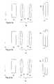
- FIG. 6 ashows an image of a sheet-metal metal part obtained at a wavelength of 700 nm using a Canon 70-200 mm F/4 mm zoom lens as the image-forming system in the system of FIGS. 1 and 2 illustrating a chromatic defect in the absence of dynamic correction, namely the image is out of focus.
- FIG. 6 bshows an image of the same sample under identical conditions as in FIG. 6 a , except that filter 12 was tuned to a wavelength of 800 nm.
- FIG. 7 ashows an image obtained under the same conditions as FIG. 6 a , except the positions X i ( ⁇ ) of lenses 13 and 14 were set to their near-optimum positions for 700 nm.
- FIG. 7 bshows the corresponding image when filter 12 is tuned to 800 nm and the positions X i ( ⁇ ) are set to their near-optimum positions for 800 m.
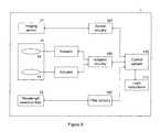
- FIG. 8shows a multispectral imaging camera (“MSC”) that receives an image at position 11 from an image-forming system or objective.
- MSCmultispectral imaging camera
- FIG. 9shows a schematic diagram of a multispectral camera system 1 that includes an imaging sensor 17 with its circuitry 107 , wavelength selection filter 12 with associated drive electronics 102 , relay lens 15 with lenses 13 and 14 controlled by actuators 103 and 104 , under control of actuator electronics 105 .
- FIG. 10is a schematic diagram showing a MSIS 500 including a image forming system 510 and a modular MSC 520 including a housing 522 that can be releasably coupled to image forming system 510 on a common platform 530 .
- the housingincludes an aperture plate 540 having an aperture 542 through which light from the imaging forming system enters the MSC.
- a BSI multispectral imaging systemacquires a spectral cube.
- a BSI systemcan be characterized by the range of wavelengths over which it collects a spectrum, which is termed the instrument's spectral range ⁇ range ; and by the range of wavelengths which participate in any individual measurement, which is termed its instantaneous bandwidth ⁇ instant .
- the bandwidthcan be described in terms of conventional measures, such as the full-width at half-maximum (FWHM) of the spectral distribution, or other measures.
- an instrumentis designed subject to the constraint that it performs well over a particular spectral range ⁇ range , which can be relatively broad.
- a multispectral camera (MSC) or multispectral imaging system (MSIS)can operate over the visible range 420-700 nm, over the range 450-850 nm, over the range 450-950 nm, over the range 500-1000 nm, or over even broader wavelength ranges.
- the instantaneous range of wavelengths ⁇ instantcan vary greatly with the application.
- the instantaneous range of wavelengthsis of order 1 nm or less, so the light is essentially monochromatic.
- ⁇ instantis more typically in the range 10-40 nm.
- even broader bandwidthsare involved.
- a BSI systemcan be used for RGB color imaging or infra-red false-color imaging.
- the instantaneous bandwidthsrange from 80 nm for visible RGB color imaging up to as much as 150 nm for infra-red false-color imaging.
- the systems and methods disclosed hereinenable an optical designer to optimize over a narrower range of wavelengths ⁇ instant rather than ⁇ range , which considerably eases the design constraints. As a result, the design criteria can be met using fewer lens elements and/or using less costly materials and/or with a higher level of performance.
- the fitness of a designcan be determined using ray-tracing methods just mentioned. Since the BSI system will be operated over the full range ⁇ range , it should perform well in a variety of configurations, corresponding to each of the various wavelength bands involved; each of these, however, has a restricted range instant over which it should perform well.
- ray-tracing programscan be used to optimize a parameter of interest—such as focus or magnification—by adjustment of the position of one or more elements in the optical system, as the system is evaluated at each of its wavelength bands.
- FIG. 1shows a schematic representation of a conventional band-sequential image (BSI) type multispectral imaging system (“MSIS”), including an image-forming system 10 which generates a first image at position 11 for light of first wavelength ⁇ , and at position 11 ′ for light of a second wavelength ⁇ ′.
- the imageralso includes a multispectral camera (“MSC”) that includes a wavelength filter 12 , relay lens 15 , and imaging sensor 17 .
- Filter 12selects a narrow range of wavelengths for transmission and substantially blocks all others.
- Relay lens 15forms a second image of the image at position 11 at location 16 for light of wavelength ⁇ , and forms a second image of the image at position 11 ′ at location 16 ′ for light of wavelength ⁇ ′.
- the size of the images at 11 ′ and at 16 ′depend upon wavelength ⁇ ′.
- Imaging sensor 17is positioned with its light-sensitive surface substantially coincident with location 16 .
- FIG. 2shows relay lens 15 used in the multispectral camera and which has inherent chromatic error.
- Lens elements 13 and 14 of the relay lensrelay an image at position 11 to position 16 when operated at wavelength ⁇ , but relay an image at position 11 to position 16 ′ when operated at wavelength ⁇ ′.
- the magnificationis unchanged with wavelength.
- the dynamic correctioncan also correct for lateral color errors.
- FIG. 3 bshows a MSC that includes a relay lens 15 , filter 12 and imaging sensor 17 , where dynamic correction is performed for inherent lateral color errors in the camera by adjusting the position of lens elements 13 and 14 to different positions illustrated as 13 ′ and 14 ′, respectively, as the filter 12 is configured to transmit light of various selected wavelength bands of interest in time sequence. Images are acquired for each wavelength band. Consequently, the image at position 11 is relayed to imaging sensor 17 at position 16 with constant magnification M( ⁇ ) for all wavelength bands.
- the dynamic correctioncan correct for both chromatic focus shift errors and lateral color errors in the MSC.
- FIG. 3 cshows a MSC that includes a relay lens 15 , filter 12 and imaging sensor 17 , where dynamic correction is performed for inherent focus shift and lateral color errors of the camera by adjusting the position of lens elements 13 and 14 to different positions illustrated as 13 ′ and 14 ′, respectively, as the filter 12 is configured to transmit light of various selected wavelength bands of interest in time sequence. Images are acquired for each wavelength band. Consequently, the image at position 11 is relayed to imaging sensor 17 at position 16 in sharp focus and with constant magnification M( ⁇ ) for all wavelength bands.
- the dynamic correction in the MSCalso corrects for chromatic errors in the image forming system.
- FIG. 4 ashows a MSIS that includes image-forming system 10 , and a MSC including relay lens 15 , filter 12 and imaging sensor 17 , where dynamic correction is performed for focus shift in the image-forming system 10 and in the relay lens 15 by adjusting the position of lens elements 13 and 14 to different positions illustrated as 13 ′ and 14 ′, respectively, as the filter 12 is configured to transmit light of various selected wavelength bands of interest in time sequence. Images are acquired for each wavelength band. When wavelength ⁇ is selected, the image at position 11 is relayed to imaging sensor 17 at position 16 , and when wavelength ⁇ ′ is selected, the image at position 11 ′ is relayed to the same position. Thus the image is in focus for all wavelength bands.
- FIG. 4 bshows a MSIS that includes image-forming system 10 , and a MSC including relay lens 15 , filter 12 and imaging sensor 17 , where dynamic correction is performed to correct lateral color errors in the image-forming system 10 and in the relay lens 15 by adjusting the position of lens elements 13 and 14 to different positions illustrated as 13 ′ and 14 ′, respectively, as the filter 12 is configured to transmit light of various selected wavelength bands of interest in time sequence. Images are acquired for each wavelength band. Consequently, the image at position 11 is relayed to imaging sensor 17 at position 16 with magnification M( ⁇ ) that is chosen so that the overall magnification of the system 1 is substantially the same for all wavelength bands.
- M( ⁇ )magnification
- FIG. 4 cshows a MSIS that includes image-forming system 10 , and MSC including relay lens 15 , filter 12 and imaging sensor 17 , where dynamic correction is performed for focus shift and lateral color errors in the image-forming system 10 and in the relay lens 15 by adjusting the position of lens elements 13 and 14 to different positions illustrated as 13 ′ and 14 ′, respectively, as the filter 12 is configured to transmit light of various selected wavelength bands of interest in time sequence. Images are acquired for each wavelength band.
- magnifications M( ⁇ )are chosen so the overall magnification of system 1 is substantially the same for all wavelength bands.
- FIGS. 6 a , 6 b , 7 a , and 7 bAdvantages of the dynamic correction is illustrated in FIGS. 6 a , 6 b , 7 a , and 7 b.
- FIG. 6 ashows an image of a sheet-metal metal part obtained at a wavelength of 700 nm using a Canon 70-200 mm F/4 mm zoom lens as the image-forming system.
- the positions of lens groups 13 and 14 in relay lens 15denoted as X i ( ⁇ ) were fixed and the system was focused while filter 12 was tuned to 550 nm. Then, filter 12 was tuned to 700 nm and an image was taken; this is shown as FIG. 6 a . At least one chromatic defect is readily apparent, namely it is clearly out of focus.
- FIG. 6 bshows an image of the same sample under identical conditions, except that filter 12 was tuned to a wavelength of 800 nm. Even greater defocusing is apparent, relative to FIG. 6 a.
- FIG. 7 ashows an image obtained under the same conditions as FIG. 6 a , except the positions X i ( ⁇ ) of lenses 13 and 14 were set to their near-optimum positions for 700 nm. Essentially all the image degradation has been removed by through this compensation.
- FIG. 7 bshows the corresponding image when filter 12 is tuned to 800 nm and the positions X i ( ⁇ ) are set to their near-optimum positions for 800 m. Again an excellent image was obtained, representing an even greater degree of improvement over the uncorrected image.
- FIG. 9shows a schematic diagram of the MSC including additional components.
- the MSCincludes includes an imaging sensor 17 with its circuitry 107 , wavelength selection filter 12 with associated drive electronics 102 , relay lens 15 with lenses 13 and 14 controlled by actuators 103 and 104 , under control of actuator electronics 105 .
- Control system 110controls the acquisition, including the selection of wavelength, control of actuators, and readout of images.
- Software or firmware 111can include instructions or logic used by control system 110 .
- elements which have small sizecan be chosen so that they can be easily and rapidly moved as desired.
- the range and physical extentshould be compatible with the overall layout of the apparatus, and the need for actuators can limit the placement of optical elements to some degree.
- a sensitivity of order unitymay be accepted for the primary focus-shift corrector, meaning that its motion is axial to an amount that is of the same order of magnitude as the pixel resolution of the image.
- the motion actuationcan be performed using any mechanism that suits the design at hand. Potential mechanisms include flexural members, precision linear slides, multiple point kinematic motion. Actuation can be performed using linear or rotary stepper motors, voice coils, or any other devices that provide the necessary mechanical motion and precision. Motion can be open-loop, or alternatively one use closed-loop motion control which takes advantage of information from a sensor such as one or more LVDT elements, or encoders, or proximity sensors, or homing position sensors.
- the wavelength selection elementcan be an electrically-tunable filter such as a liquid crystal tunable filter (LCTF) or acousto-optic tunable filter (AOTF), a mechanical filter wheel which presents a selected filter into the beam under electronic control, or any other element which transmits one selected wavelength band at a time from within a larger range of wavelengths. It is preferable that the wavelength selection not introduce displacement of the image, but if the displacement is systematic it may be removed under software control. If the wavelength selection element introduces systematic focus shift or lateral color, these can be actively compensated away by systems and methods disclosed herein.
- LCTFliquid crystal tunable filter
- AOTFacousto-optic tunable filter
- FIG. 10is a schematic diagram showing a MSIS 500 including a image forming system 510 , including a housing 512 and image forming optics 514 , and a modular MSC 520 including a housing 522 that can be releasably coupled to the housing 512 for the image forming system 510 on a common platform 530 so that light from the image forming optics can enter the MSC.
- the MSC housing 522includes an aperture plate 540 having an aperture 542 through which light from the imaging forming optics enters the MSC.
- the imaging forming systemcan be a microscope (such one used for fluorescence imaging), a telescope, or a camera lens (such as one suitable small animal imaging).
- a common MSCcan be used with a wide variety of image forming system.
- FIG. 8shows a details optical system for a MSC, which receives an image at position 11 from an image-forming system or objective, and includes prefilter 81 , liquid crystal tunable filter 82 , lenses 80 a - 80 k , and imaging sensor 87 having cooling window 88 and sensor window 89 .
- the position of lens 80 ais adjustable about nominal position 83
- lenses 80 j - kform a lens group whose position 85 is adjustable.
- the positions of lenses 80 b - iare fixed.
- the lens prescription and positional arrangementis shown in Table 1 below. Specific optical parameters for the optical elements are described in Table 1 below.
- the dynamic correctionadjusts the position of lens 80 a and the position of the group of lenses 80 j and 80 k to optimize focus and maintain constant magnification as the wavelength band is changed.
- a ray tracing program optimizationprovides an exemplary set of positions X i ( ⁇ ) to which the corresponding lens elements are set to provide dynamic correction of chromatic aberrations. This system performs well over the range 500-950 nm, and provides more than 10 distinct wavelength bands, or more than 16 overlapping bands.
- one strategy for developing a designis to optimize the overall optical system for performance at a first wavelength, such as a mid-band wavelength, in the conventional manner, and then to explore which elements provide the necessary adjustment freedom.
- This strategywill be understood by those skilled in the art of lens design, but one may employ variations on this strategy, or other strategies, so long as the result is a design which meets the needs at hand.
- the systems and methods disclosed hereininclude the ability to correct for deficiencies in the multispectral camera (MSC).
- MSCmultispectral camera
- the positions X i ( ⁇ )may not be optimum, as the image-forming system coupled to the MSC brings its own contributions to focus shift and lateral color. Accordingly, these can be developed these in situ with the complete instrument participating in the measurement.
- FIG. 5shows a flow chart for how the settings X i ( ⁇ ) may be obtained in situ and then used to dynamically correct for image defects.
- the targetis free of complex spatial-spectral structure.
- X i ( ⁇ )For example, it would be possible, but relatively difficult, to determine the best X i ( ⁇ ) for an MSC which spanned the 400-700 nm visible range, using a target of colored polka-dots, if each one spanned only a single color; X i ( ⁇ ) would have to be established for several sub-ranges, together with correspondences between the sub-ranges.
- a target of black spotsis typically easier to use.
- the MSCis configured with its actuators set to the values of X i ( ⁇ ) which correct its intrinsic errors, but not those of the microscope, and an image is taken with the wavelength selection element 12 set to transmit a first wavelength.
- the microscope focusis adjusted until the sharpest image is attained, using its stage or other means.
- the wavelength selectionis changed to transmit a second wavelength, while the microscope focus is unchanged.
- the MSCis configured to a range of X i ( ⁇ ) settings while optimum focus and magnification are sought; the resulting settings are recorded as the target X i ( ⁇ ) for the combined instrument. Cycling through all wavelengths and repeating this process continues until a complete set of configurations X i ( ⁇ ) is attained.
- the optimum or near-optimum settingsdepend on the objective, the tube lens or projection lens, and other optics which may be present in the microscope.
- different settings X i ( ⁇ )are used to apply proper correction. Since the deficiencies of a given microscope are relatively stable for a given configuration of components, it is useful to perform the in situ characterization once and store the set of all X i ( ⁇ ) corresponding to the microscope configurations of interest; these can then be rapidly summoned forth under software control.
- an MSCcan be constructed which corrects for components such as microscope objectives, and whose performance is viewed as a fixed constraint by an end-user or system designer. Even apochromatic objectives are not free of focus shift or lateral color, and can introduce artifacts into multispectral image cubes. Achromatic objectives present the same problem, often to a greater degree.
- the objectivemeets other requirements which are fundamentally incompatible with good achromatization, or which are costly to achieve in concert with this goal.
- fluorescence microscopythere are a limited set of materials due to requirements such as the need to tolerate and transmit ultraviolet light, to be relatively free of fluorescence, and so on. This is necessary because fluorescence microscopes both transmit ultraviolet radiation (e.g., less than or equal to about 440 nm) to the sample and collect fluorescence from the sample at larger wavelengths (e.g., greater than or equal to about 450 nm.) Consequently, these objectives often have relatively high degree of focus shift with wavelength, and of lateral color, compared to other objectives such as apochromatic objectives.
- the systems and methods disclosed hereinare especially valuable in settings where one wishes to obtain fluorescence imagery over a wide range of wavelengths ⁇ range , such as over a range of 100 nm or more.
- fluorescent dyeswhich emit in the red or infrared portion of the spectrum.
- examples of theseinclude the Cy3.5, Cy5, and Cy5.5 from Amersham Biosciences (Piscataway, N.J.), IR800 from Li-Cor Biosciences (Lincoln, Nebr.), and others.
- probesbased on quantum dots which emit in the red and near-infrared portion of the spectrum.
- the above agentsare often used in concert with one another, and with probes which emit in the blue and green portions of the visible, such as DAPI, fluorescein, Hoechst, and others.
- multiple probesare present in the same sample for purposes of multiplexed labeling, and it is desired that the relative positions of each probe be accurately identified. This places new demands on the imaging system, since a given sample can include emissions spanning 100 nm or more, or 200 nm or more, or which extend into the infrared where existing microscope performance is generally degraded compared to the visible.
- the systems and methods disclosed hereincan correct for focus shift and lateral color without modification to the microscope or objective.
- a further important aspect of the disclosed systems and methodsis that, since all aspects of the MSC system are retained, it is possible to optimize the coordination of dynamic correction of focus with image acquisition, in a single piece of software.
- the systems and methods disclosed hereineliminate the possibility of unwanted lateral motion, and provide for correcting the lateral color. Absent this correction, the image can be re-focused, but the relative size of an object in one plane of the spectral cube may not precisely match the size of that same object in another plane. Errors of two or more pixels are commonly seen in the corner of a megapixel image, even for a research-grade microscope.
- the disclosed systems and methodscan be used for imaging macroscopic objects (e.g., small animals in medical studies) across the visible and near-infrared range.
- the systems and methodscorrect these defects so their effect is reduced or eliminated, resulting in a great performance improvement.
- the systems and methodsprovide a way to use commercial camera lenses, which have low cost and high optical performance in the visible region. This is a often preferred alternative to making a custom lens that exhibits less infrared chromatic distortion, since doing so involves significant cost, time, and expertise.
Landscapes
- Physics & Mathematics (AREA)
- General Physics & Mathematics (AREA)
- Spectroscopy & Molecular Physics (AREA)
- Optics & Photonics (AREA)
- Analytical Chemistry (AREA)
- Chemical & Material Sciences (AREA)
- Multimedia (AREA)
- Engineering & Computer Science (AREA)
- Health & Medical Sciences (AREA)
- Toxicology (AREA)
- Microscoopes, Condenser (AREA)
- Automatic Focus Adjustment (AREA)
- Spectrometry And Color Measurement (AREA)
Abstract
Description
| TABLE 1 | |||||||
| Item | Position | R1 | R2 | Thick | Description | ||
| 11 | 0 | — | — | — | — | |
| 81 | 10 | — | — | BK7 | 3 | Pre-filter |
| 82 | 19 | — | — | various | 37.8 | |
| 80a | 147.4 | 220.6 | −100 | S-BSM16 | 9.3 | |
| 80b | 160.4 | 90.4 | −85.9 | S-BSM16 | 14.65 | Lens 2 |
| 80c | 175.0 | −85.9 | 216.0 | S-NBH5 | 9 | Lens 3 |
| 80d | 192.5 | 32.0 | −79.4 | S-BSM16 | 18.24 | Lens 4 |
| 80e | 215.0 | −79.4 | 16.0 | S-NBH5 | 4.58 | Lens 5 |
| 80f | 210.7 | −17.3 | 29.0 | S-NBH5 | 4.25 | Lens 6 |
| 80g | 228.0 | 29.0 | −25.2 | S-BSM16 | 11.78 | Lens 7 |
| 80h | 239.8 | 22.4 | −216.0 | S-BSM16 | 9.92 | Lens 8 |
| 80i | 252.8 | −34.5 | 19.9 | S-NBM51 | 3 | Lens 9 |
| 80j | 265.2 | 107.4 | −33.0 | S-BSM16 | 5 | |
| 80k | 271.8 | 19.9 | 56.8 | S-BSM16 | 6.56 | |
| 88 | 293.3 | — | — | BK7 | 1.1 | Sensor |
| window | ||||||
| 89 | 297.9 | — | — | N-BK10 | 0.7 | |
| 87 | 299.3 | — | — | — | — | Imaging sensor |
Claims (52)
Priority Applications (1)
| Application Number | Priority Date | Filing Date | Title |
|---|---|---|---|
| US12/251,632US8330087B2 (en) | 2007-10-16 | 2008-10-15 | Spectral imaging system with dynamic optical correction |
Applications Claiming Priority (2)
| Application Number | Priority Date | Filing Date | Title |
|---|---|---|---|
| US98031007P | 2007-10-16 | 2007-10-16 | |
| US12/251,632US8330087B2 (en) | 2007-10-16 | 2008-10-15 | Spectral imaging system with dynamic optical correction |
Publications (2)
| Publication Number | Publication Date |
|---|---|
| US20090096914A1 US20090096914A1 (en) | 2009-04-16 |
| US8330087B2true US8330087B2 (en) | 2012-12-11 |
Family
ID=40325906
Family Applications (1)
| Application Number | Title | Priority Date | Filing Date |
|---|---|---|---|
| US12/251,632Active2030-02-22US8330087B2 (en) | 2007-10-16 | 2008-10-15 | Spectral imaging system with dynamic optical correction |
Country Status (2)
| Country | Link |
|---|---|
| US (1) | US8330087B2 (en) |
| EP (1) | EP2051051B1 (en) |
Cited By (57)
| Publication number | Priority date | Publication date | Assignee | Title |
|---|---|---|---|---|
| US20140015951A1 (en)* | 2012-04-12 | 2014-01-16 | Thomas Nathan Millikan | Viewing and processing multispectral images |
| US9042967B2 (en) | 2008-05-20 | 2015-05-26 | University Health Network | Device and method for wound imaging and monitoring |
| WO2016106954A1 (en)* | 2014-12-30 | 2016-07-07 | 华中科技大学 | Low-orbit satellite-borne spectrogram correlation detection method and load |
| WO2016106953A1 (en)* | 2014-12-30 | 2016-07-07 | 华中科技大学 | Infrared spectrogram correlation detection system and method for mobile platform |
| WO2016106956A1 (en)* | 2014-12-30 | 2016-07-07 | 华中科技大学 | Infrared spectrogram correlation intelligent detection method and apparatus |
| US10330927B2 (en) | 2015-03-04 | 2019-06-25 | Carl Zeiss Meditec Ag | Optical system and surgical microscope |
| US10438356B2 (en) | 2014-07-24 | 2019-10-08 | University Health Network | Collection and analysis of data for diagnostic purposes |
| WO2021206768A1 (en)* | 2020-04-06 | 2021-10-14 | Rarecyte, Inc. | Optical trains for imaging systems and spectral edge detection |
| WO2022020340A1 (en) | 2020-07-20 | 2022-01-27 | Akoya Biosciences, Inc. | Processing and imaging tissue samples |
| US11352667B2 (en) | 2016-06-21 | 2022-06-07 | 10X Genomics, Inc. | Nucleic acid sequencing |
| US11359966B2 (en) | 2019-04-17 | 2022-06-14 | Westboro Photonics Inc. | System, method and apparatus for wide wavelength range imaging with focus and image correction |
| US11432712B2 (en) | 2017-06-28 | 2022-09-06 | Karl Storz Imaging, Inc. | Fluorescence imaging scope with dual mode focusing structures |
| US11542543B2 (en) | 2010-04-05 | 2023-01-03 | Prognosys Biosciences, Inc. | System for analyzing targets of a tissue section |
| US11555219B2 (en) | 2019-05-31 | 2023-01-17 | 10X Genomics, Inc. | Method of detecting target nucleic acid molecules |
| US11553837B2 (en) | 2020-03-02 | 2023-01-17 | Karl Storz Se & Co Kg | Medical imaging device with multiple imaging modes |
| US11566277B2 (en) | 2011-12-22 | 2023-01-31 | President And Fellows Of Harvard College | Compositions and methods for analyte detection |
| US11597965B2 (en) | 2017-10-06 | 2023-03-07 | 10X Genomics, Inc. | RNA templated ligation |
| US11613773B2 (en) | 2015-04-10 | 2023-03-28 | Spatial Transcriptomics Ab | Spatially distinguished, multiplex nucleic acid analysis of biological specimens |
| US11618918B2 (en) | 2013-06-25 | 2023-04-04 | Prognosys Biosciences, Inc. | Methods and systems for determining spatial patterns of biological targets in a sample |
| US11713485B2 (en) | 2016-04-25 | 2023-08-01 | President And Fellows Of Harvard College | Hybridization chain reaction methods for in situ molecular detection |
| US11733238B2 (en) | 2010-04-05 | 2023-08-22 | Prognosys Biosciences, Inc. | Spatially encoded biological assays |
| US11788122B2 (en) | 2011-04-13 | 2023-10-17 | 10X Genomics Sweden Ab | Methods of detecting analytes |
| US11866767B2 (en) | 2020-05-22 | 2024-01-09 | 10X Genomics, Inc. | Simultaneous spatio-temporal measurement of gene expression and cellular activity |
| US12031177B1 (en) | 2020-06-04 | 2024-07-09 | 10X Genomics, Inc. | Methods of enhancing spatial resolution of transcripts |
| USRE50065E1 (en) | 2012-10-17 | 2024-07-30 | 10X Genomics Sweden Ab | Methods and product for optimising localised or spatial detection of gene expression in a tissue sample |
| US12060603B2 (en) | 2021-01-19 | 2024-08-13 | 10X Genomics, Inc. | Methods for internally controlled in situ assays using padlock probes |
| US12071667B2 (en) | 2020-11-04 | 2024-08-27 | 10X Genomics, Inc. | Sequence analysis using meta-stable nucleic acid molecules |
| US12098425B2 (en) | 2018-10-10 | 2024-09-24 | Readcoor, Llc | Three-dimensional spatial molecular indexing |
| US12098985B2 (en) | 2021-02-19 | 2024-09-24 | 10X Genomics, Inc. | Modular assay support devices |
| US12110548B2 (en) | 2020-02-03 | 2024-10-08 | 10X Genomics, Inc. | Bi-directional in situ analysis |
| US12116626B2 (en) | 2022-08-16 | 2024-10-15 | 10X Genomics, Inc. | AP50 polymerases and uses thereof |
| US12139751B2 (en) | 2021-07-30 | 2024-11-12 | 10X Genomics, Inc. | Circularizable probes for in situ analysis |
| US12157124B2 (en) | 2019-11-06 | 2024-12-03 | 10X Genomics, Inc. | Imaging system hardware |
| US12173360B2 (en) | 2020-02-21 | 2024-12-24 | 10X Genomics, Inc. | Methods and compositions for integrated in situ spatial assay |
| US12188085B2 (en) | 2020-03-05 | 2025-01-07 | 10X Genomics, Inc. | Three-dimensional spatial transcriptomics with sequencing readout |
| US12203136B2 (en) | 2020-08-17 | 2025-01-21 | Readcoor, Llc | Methods and systems for spatial mapping of genetic variants |
| US12209273B2 (en) | 2020-06-12 | 2025-01-28 | 10X Genomics, Inc. | Nucleic acid assays using click chemistry bioconjugation |
| US12215379B2 (en) | 2020-02-17 | 2025-02-04 | 10X Genomics, Inc. | In situ analysis of chromatin interaction |
| US12223751B2 (en) | 2021-12-20 | 2025-02-11 | 10X Genomics, Inc. | Self-test for imaging device |
| USD1064308S1 (en) | 2021-09-17 | 2025-02-25 | 10X Genomics, Inc. | Sample handling device |
| US12234507B2 (en) | 2022-04-01 | 2025-02-25 | 10X Genomics, Inc. | Compositions and methods for targeted masking of autofluorescence |
| US12249085B2 (en) | 2020-09-18 | 2025-03-11 | 10X Genomics, Inc. | Sample handling apparatus and image registration methods |
| US12258624B2 (en) | 2022-06-17 | 2025-03-25 | 10X Genomics, Inc. | Catalytic de-crosslinking of samples for in situ analysis |
| US12264358B2 (en) | 2013-03-12 | 2025-04-01 | President And Fellows Of Harvard College | Method of selectively sequencing amplicons in a biological sample |
| US12270071B2 (en) | 2019-12-20 | 2025-04-08 | 10X Genomics, Inc. | Methods of detecting an analyte |
| US12270074B1 (en) | 2022-05-11 | 2025-04-08 | 10X Genomics, Inc. | Compositions and methods for gene expression library analysis |
| US12275984B2 (en) | 2021-03-02 | 2025-04-15 | 10X Genomics, Inc. | Sequential hybridization and quenching |
| US12297499B2 (en) | 2020-08-17 | 2025-05-13 | 10X Genomics, Inc. | Multicomponent nucleic acid probes for sample analysis |
| EP4560319A1 (en) | 2023-11-24 | 2025-05-28 | Pierre Fabre Medicament | Immune and tumour cells expression of vista in a panel of cancer indications |
| US12319956B2 (en) | 2023-07-31 | 2025-06-03 | 10X Genomics, Inc. | Methods and systems for targeted RNA cleavage and target RNA-primed rolling circle amplification |
| US12331347B2 (en) | 2014-07-11 | 2025-06-17 | President And Fellows Of Harvard College | Methods for high-throughput labelling and detection of biological features in situ using microscopy |
| US12360105B2 (en) | 2021-07-30 | 2025-07-15 | 10X Genomics, Inc. | Methods and compositions for synchronizing reactions in situ |
| US12391984B2 (en) | 2021-08-03 | 2025-08-19 | 10X Genomics, Inc. | Compositions and methods for rolling circle amplification |
| US12400733B2 (en) | 2022-03-08 | 2025-08-26 | 10X Genomics, Inc. | In situ code design methods for minimizing optical crowding |
| US12405264B2 (en) | 2020-01-17 | 2025-09-02 | 10X Genomics, Inc. | Electrophoretic system and method for analyte capture |
| US12416603B2 (en) | 2020-05-19 | 2025-09-16 | 10X Genomics, Inc. | Electrophoresis cassettes and instrumentation |
| US12435364B2 (en) | 2021-08-16 | 2025-10-07 | 10X Genomics, Inc. | Probes comprising a split barcode region and methods of use |
Families Citing this family (20)
| Publication number | Priority date | Publication date | Assignee | Title |
|---|---|---|---|---|
| US8164061B2 (en)* | 2006-09-13 | 2012-04-24 | Delphi Technologies, Inc. | Method and apparatus for a universal infrared analyzer |
| US20100079748A1 (en)* | 2008-09-30 | 2010-04-01 | Asml Holding N.V. | Inspection Apparatus, Lithographic Apparatus and Method for Sphero-Chromatic Aberration Correction |
| DK2406679T3 (en) | 2009-03-11 | 2017-04-18 | Sakura Finetek Usa Inc | AUTO FOCUS PROCEDURE AND AUTO FOCUS DEVICE |
| US8143565B2 (en)* | 2009-09-30 | 2012-03-27 | Ricoh Co., Ltd. | Adjustable multimode lightfield imaging system having an actuator for changing position of a non-homogeneous filter module relative to an image-forming optical module |
| US10139613B2 (en)* | 2010-08-20 | 2018-11-27 | Sakura Finetek U.S.A., Inc. | Digital microscope and method of sensing an image of a tissue sample |
| JP5738564B2 (en)* | 2010-09-30 | 2015-06-24 | オリンパス株式会社 | Image processing system |
| US8949078B2 (en) | 2011-03-04 | 2015-02-03 | Ricoh Co., Ltd. | Filter modules for aperture-coded, multiplexed imaging systems |
| CN102243763B (en)* | 2011-05-23 | 2013-03-13 | 华中科技大学 | Infrared imaging spectrum optimization and selection method under high-speed conditions |
| US9921396B2 (en)* | 2011-07-17 | 2018-03-20 | Ziva Corp. | Optical imaging and communications |
| GB201219171D0 (en)* | 2012-10-25 | 2012-12-12 | Epipole Ltd | Image acquisition apparatus |
| US9219866B2 (en) | 2013-01-07 | 2015-12-22 | Ricoh Co., Ltd. | Dynamic adjustment of multimode lightfield imaging system using exposure condition and filter position |
| EP2757356A1 (en)* | 2013-01-22 | 2014-07-23 | SwissOptic AG | Multispectral optical device |
| DE102013103971A1 (en) | 2013-04-19 | 2014-11-06 | Sensovation Ag | Method for generating an overall picture of an object composed of several partial images |
| US9030580B2 (en) | 2013-09-28 | 2015-05-12 | Ricoh Company, Ltd. | Color filter modules for plenoptic XYZ imaging systems |
| US10007102B2 (en) | 2013-12-23 | 2018-06-26 | Sakura Finetek U.S.A., Inc. | Microscope with slide clamping assembly |
| WO2015198331A1 (en)* | 2014-06-25 | 2015-12-30 | Ramot At Tel-Aviv University Ltd. | System and method for light-field imaging |
| CN104713648A (en)* | 2015-04-08 | 2015-06-17 | 四川双利合谱科技有限公司 | Full-wave-band achromatism filter type spectral camera |
| US11280803B2 (en) | 2016-11-22 | 2022-03-22 | Sakura Finetek U.S.A., Inc. | Slide management system |
| US11193950B2 (en) | 2019-03-29 | 2021-12-07 | Sakura Finetek U.S.A., Inc. | Slide identification sensor |
| CN111854950A (en)* | 2020-07-30 | 2020-10-30 | 中国科学院长春光学精密机械与物理研究所 | Optical system of a multiple image plane spectrometer |
Citations (28)
| Publication number | Priority date | Publication date | Assignee | Title |
|---|---|---|---|---|
| US5521705A (en) | 1994-05-12 | 1996-05-28 | Oldenbourg; Rudolf | Polarized light microscopy |
| US5539517A (en) | 1993-07-22 | 1996-07-23 | Numetrix Ltd. | Method for simultaneously measuring the spectral intensity as a function of wavelength of all the pixels of a two dimensional scene |
| US5784162A (en) | 1993-08-18 | 1998-07-21 | Applied Spectral Imaging Ltd. | Spectral bio-imaging methods for biological research, medical diagnostics and therapy |
| WO1998043042A1 (en) | 1997-03-25 | 1998-10-01 | Applied Spectral Imaging Ltd. | Spectral bio-imaging methods for cell classification |
| US5834203A (en)* | 1997-08-25 | 1998-11-10 | Applied Spectral Imaging | Method for classification of pixels into groups according to their spectra using a plurality of wide band filters and hardwire therefore |
| US5995645A (en) | 1993-08-18 | 1999-11-30 | Applied Spectral Imaging Ltd. | Method of cancer cell detection |
| US6142629A (en) | 1998-08-30 | 2000-11-07 | Applied Spectral Imaging Ltd. | Spectral imaging using illumination of preselected spectral content |
| US20020030755A1 (en)* | 2000-09-11 | 2002-03-14 | Fumiko Uchino | Digital image sensing apparatus, image processing system, and digital image sensing method |
| US6373568B1 (en) | 1999-08-06 | 2002-04-16 | Cambridge Research & Instrumentation, Inc. | Spectral imaging system |
| US6421131B1 (en) | 1999-07-02 | 2002-07-16 | Cambridge Research & Instrumentation Inc. | Birefringent interferometer |
| US20030081204A1 (en) | 2001-08-23 | 2003-05-01 | Cronin Paul J. | Spectral imaging |
| US20030138140A1 (en) | 2002-01-24 | 2003-07-24 | Tripath Imaging, Inc. | Method for quantitative video-microscopy and associated system and computer software program product |
| US20030153825A1 (en)* | 2002-02-12 | 2003-08-14 | Science & Engineering Associates, Inc. | Cancer detection and adaptive dose optimization treatment system |
| US20030223248A1 (en) | 2002-06-04 | 2003-12-04 | Cronin Paul J. | Multispectral imaging system |
| US20040245430A1 (en)* | 2003-06-05 | 2004-12-09 | Kazuki Konishi | Autofocus control apparatus and method |
| US20050065440A1 (en) | 2003-09-23 | 2005-03-24 | Richard Levenson | Spectral imaging of deep tissue |
| US6920239B2 (en) | 1995-11-30 | 2005-07-19 | Chromavision Medical Systems, Inc. | Method and apparatus for automated image analysis of biological specimens |
| US6924893B2 (en) | 2002-05-13 | 2005-08-02 | Marine Biological Laboratory | Enhancing polarized light microscopy |
| US20060082762A1 (en) | 2003-03-26 | 2006-04-20 | Chad Leverette | Automated polarized light microscope combined with a spectroscopy/spectral imaging apparatus |
| US20060119865A1 (en) | 2004-12-06 | 2006-06-08 | Hoyt Clifford C | Systems and methods for in-vivo optical imaging and measurement |
| WO2006081547A1 (en) | 2005-01-27 | 2006-08-03 | Cambridge Research And Instrumentation, Inc. | Classifying image features |
| US20070159541A1 (en)* | 2006-01-09 | 2007-07-12 | Sparks Andrew W | Single camera multi-spectral imager |
| US20070231784A1 (en) | 2006-04-04 | 2007-10-04 | Hoyt Clifford C | Quantitation of oocytes and biological samples using birefringent imaging |
| US20080074644A1 (en) | 2006-09-25 | 2008-03-27 | Cambridge Research And Instrumentation, Inc. | Sample imaging and classification |
| US20090226059A1 (en) | 2008-02-12 | 2009-09-10 | Richard Levenson | Tissue Processing And Assessment |
| US20090257640A1 (en) | 2008-03-10 | 2009-10-15 | Kirk William Gossage | Classification of samples |
| US20100075373A1 (en) | 2008-09-22 | 2010-03-25 | Hoyt Clifford C | Multi-Spectral Imaging Including At Least One Common Stain |
| US20110182490A1 (en) | 2009-08-10 | 2011-07-28 | Hoyt Clifford C | Visualization of stained samples |
Family Cites Families (3)
| Publication number | Priority date | Publication date | Assignee | Title |
|---|---|---|---|---|
| EP1231496B1 (en)* | 1994-08-18 | 2004-12-29 | Carl Zeiss AG | Optical coherence tomography assisted surgical apparatus |
| WO1996037797A1 (en)* | 1995-05-26 | 1996-11-28 | General Scanning, Inc. | Wide field of view microscope and scanning system useful in the microscope |
| JP4914715B2 (en)* | 2004-06-21 | 2012-04-11 | オリンパス株式会社 | Inverted microscope system |
- 2008
- 2008-10-15EPEP08018046.6Apatent/EP2051051B1/enactiveActive
- 2008-10-15USUS12/251,632patent/US8330087B2/enactiveActive
Patent Citations (38)
| Publication number | Priority date | Publication date | Assignee | Title |
|---|---|---|---|---|
| US5991028A (en) | 1991-02-22 | 1999-11-23 | Applied Spectral Imaging Ltd. | Spectral bio-imaging methods for cell classification |
| US5539517A (en) | 1993-07-22 | 1996-07-23 | Numetrix Ltd. | Method for simultaneously measuring the spectral intensity as a function of wavelength of all the pixels of a two dimensional scene |
| US5784162A (en) | 1993-08-18 | 1998-07-21 | Applied Spectral Imaging Ltd. | Spectral bio-imaging methods for biological research, medical diagnostics and therapy |
| US5995645A (en) | 1993-08-18 | 1999-11-30 | Applied Spectral Imaging Ltd. | Method of cancer cell detection |
| US5521705A (en) | 1994-05-12 | 1996-05-28 | Oldenbourg; Rudolf | Polarized light microscopy |
| US6920239B2 (en) | 1995-11-30 | 2005-07-19 | Chromavision Medical Systems, Inc. | Method and apparatus for automated image analysis of biological specimens |
| US6007996A (en) | 1995-12-12 | 1999-12-28 | Applied Spectral Imaging Ltd. | In situ method of analyzing cells |
| WO1998043042A1 (en) | 1997-03-25 | 1998-10-01 | Applied Spectral Imaging Ltd. | Spectral bio-imaging methods for cell classification |
| US5834203A (en)* | 1997-08-25 | 1998-11-10 | Applied Spectral Imaging | Method for classification of pixels into groups according to their spectra using a plurality of wide band filters and hardwire therefore |
| US6142629A (en) | 1998-08-30 | 2000-11-07 | Applied Spectral Imaging Ltd. | Spectral imaging using illumination of preselected spectral content |
| US6421131B1 (en) | 1999-07-02 | 2002-07-16 | Cambridge Research & Instrumentation Inc. | Birefringent interferometer |
| US6373568B1 (en) | 1999-08-06 | 2002-04-16 | Cambridge Research & Instrumentation, Inc. | Spectral imaging system |
| US6690466B2 (en) | 1999-08-06 | 2004-02-10 | Cambridge Research & Instrumentation, Inc. | Spectral imaging system |
| US20020030755A1 (en)* | 2000-09-11 | 2002-03-14 | Fumiko Uchino | Digital image sensing apparatus, image processing system, and digital image sensing method |
| US20030081204A1 (en) | 2001-08-23 | 2003-05-01 | Cronin Paul J. | Spectral imaging |
| US20030138140A1 (en) | 2002-01-24 | 2003-07-24 | Tripath Imaging, Inc. | Method for quantitative video-microscopy and associated system and computer software program product |
| US20030153825A1 (en)* | 2002-02-12 | 2003-08-14 | Science & Engineering Associates, Inc. | Cancer detection and adaptive dose optimization treatment system |
| US6924893B2 (en) | 2002-05-13 | 2005-08-02 | Marine Biological Laboratory | Enhancing polarized light microscopy |
| US20030223248A1 (en) | 2002-06-04 | 2003-12-04 | Cronin Paul J. | Multispectral imaging system |
| US6825930B2 (en) | 2002-06-04 | 2004-11-30 | Cambridge Research And Instrumentation, Inc. | Multispectral imaging system |
| US20060082762A1 (en) | 2003-03-26 | 2006-04-20 | Chad Leverette | Automated polarized light microscope combined with a spectroscopy/spectral imaging apparatus |
| US20040245430A1 (en)* | 2003-06-05 | 2004-12-09 | Kazuki Konishi | Autofocus control apparatus and method |
| US20070016082A1 (en) | 2003-09-23 | 2007-01-18 | Richard Levenson | Spectral imaging |
| US20050065440A1 (en) | 2003-09-23 | 2005-03-24 | Richard Levenson | Spectral imaging of deep tissue |
| US7321791B2 (en) | 2003-09-23 | 2008-01-22 | Cambridge Research And Instrumentation, Inc. | Spectral imaging of deep tissue |
| WO2005040769A2 (en) | 2003-09-23 | 2005-05-06 | Cambridge Research And Instrumentation, Inc. | Spectral imaging of biological samples |
| US20060119865A1 (en) | 2004-12-06 | 2006-06-08 | Hoyt Clifford C | Systems and methods for in-vivo optical imaging and measurement |
| US20060245631A1 (en) | 2005-01-27 | 2006-11-02 | Richard Levenson | Classifying image features |
| WO2006081547A1 (en) | 2005-01-27 | 2006-08-03 | Cambridge Research And Instrumentation, Inc. | Classifying image features |
| US20070159541A1 (en)* | 2006-01-09 | 2007-07-12 | Sparks Andrew W | Single camera multi-spectral imager |
| US20070231784A1 (en) | 2006-04-04 | 2007-10-04 | Hoyt Clifford C | Quantitation of oocytes and biological samples using birefringent imaging |
| US20080074644A1 (en) | 2006-09-25 | 2008-03-27 | Cambridge Research And Instrumentation, Inc. | Sample imaging and classification |
| US20080074649A1 (en) | 2006-09-25 | 2008-03-27 | Cambridge Research And Instrumentation, Inc. | Sample imaging and classification |
| WO2008039758A2 (en) | 2006-09-25 | 2008-04-03 | Cambridge Research & Instrumentation, Inc. | Sample imaging and classification |
| US20090226059A1 (en) | 2008-02-12 | 2009-09-10 | Richard Levenson | Tissue Processing And Assessment |
| US20090257640A1 (en) | 2008-03-10 | 2009-10-15 | Kirk William Gossage | Classification of samples |
| US20100075373A1 (en) | 2008-09-22 | 2010-03-25 | Hoyt Clifford C | Multi-Spectral Imaging Including At Least One Common Stain |
| US20110182490A1 (en) | 2009-08-10 | 2011-07-28 | Hoyt Clifford C | Visualization of stained samples |
Non-Patent Citations (1)
| Title |
|---|
| Andrew Rabinovich et al., "Quantitative Spectral Decomposition for Stained Tissue Analysis," UCSD Jacobs School of Engineering 24th Annual Research Expo, Feb. 25, 2005. |
Cited By (100)
| Publication number | Priority date | Publication date | Assignee | Title |
|---|---|---|---|---|
| US12226186B2 (en) | 2008-05-20 | 2025-02-18 | University Health Network | Devices, methods, and systems with spectral filtering for detecting wound and identifying bacteria based on fluorescence signature |
| US11375898B2 (en) | 2008-05-20 | 2022-07-05 | University Health Network | Method and system with spectral filtering and thermal mapping for imaging and collection of data for diagnostic purposes from bacteria |
| US9042967B2 (en) | 2008-05-20 | 2015-05-26 | University Health Network | Device and method for wound imaging and monitoring |
| US11284800B2 (en) | 2008-05-20 | 2022-03-29 | University Health Network | Devices, methods, and systems for fluorescence-based endoscopic imaging and collection of data with optical filters with corresponding discrete spectral bandwidth |
| US11154198B2 (en) | 2008-05-20 | 2021-10-26 | University Health Network | Method and system for imaging and collection of data for diagnostic purposes |
| US12251191B2 (en) | 2008-05-20 | 2025-03-18 | University Health Network | Diagnostic method and system with optical and temperature sensors for imaging and mapping fluorescence intensities of tissue |
| US11733238B2 (en) | 2010-04-05 | 2023-08-22 | Prognosys Biosciences, Inc. | Spatially encoded biological assays |
| US11542543B2 (en) | 2010-04-05 | 2023-01-03 | Prognosys Biosciences, Inc. | System for analyzing targets of a tissue section |
| US12297487B2 (en) | 2010-04-05 | 2025-05-13 | Prognosys Biosciences, Inc. | Spatially encoded biological assays |
| US11560587B2 (en) | 2010-04-05 | 2023-01-24 | Prognosys Biosciences, Inc. | Spatially encoded biological assays |
| US12391979B2 (en) | 2010-04-05 | 2025-08-19 | Prognosys Biosciences, Inc. | Spatially encoded biological assays |
| US11732292B2 (en) | 2010-04-05 | 2023-08-22 | Prognosys Biosciences, Inc. | Spatially encoded biological assays correlating target nucleic acid to tissue section location |
| US11866770B2 (en) | 2010-04-05 | 2024-01-09 | Prognosys Biosciences, Inc. | Spatially encoded biological assays |
| US12297488B2 (en) | 2010-04-05 | 2025-05-13 | Prognosys Biosciences, Inc. | Spatially encoded biological assays |
| US11634756B2 (en) | 2010-04-05 | 2023-04-25 | Prognosys Biosciences, Inc. | Spatially encoded biological assays |
| US12234505B2 (en) | 2010-04-05 | 2025-02-25 | Prognosys Biosciences, Inc. | Spatially encoded biological assays |
| US12391980B2 (en) | 2010-04-05 | 2025-08-19 | Prognosys Biosciences, Inc. | Spatially encoded biological assays |
| US11761030B2 (en) | 2010-04-05 | 2023-09-19 | Prognosys Biosciences, Inc. | Spatially encoded biological assays |
| US11767550B2 (en) | 2010-04-05 | 2023-09-26 | Prognosys Biosciences, Inc. | Spatially encoded biological assays |
| US11788122B2 (en) | 2011-04-13 | 2023-10-17 | 10X Genomics Sweden Ab | Methods of detecting analytes |
| US11795498B2 (en) | 2011-04-13 | 2023-10-24 | 10X Genomics Sweden Ab | Methods of detecting analytes |
| US11976318B2 (en) | 2011-12-22 | 2024-05-07 | President And Fellows Of Harvard College | Compositions and methods for analyte detection |
| US11566277B2 (en) | 2011-12-22 | 2023-01-31 | President And Fellows Of Harvard College | Compositions and methods for analyte detection |
| US11639518B2 (en) | 2011-12-22 | 2023-05-02 | President And Fellows Of Harvard College | Compositions and methods for analyte detection |
| US9173570B2 (en) | 2012-04-12 | 2015-11-03 | Thomas Nathan Millikan | Viewing and processing multispectral images |
| US8913118B2 (en)* | 2012-04-12 | 2014-12-16 | Thomas Nathan Millikan | Viewing and processing multispectral images |
| US9986912B2 (en) | 2012-04-12 | 2018-06-05 | Thomas Nathan Millikan | Viewing and processing multispectral images |
| US20140015951A1 (en)* | 2012-04-12 | 2014-01-16 | Thomas Nathan Millikan | Viewing and processing multispectral images |
| USRE50065E1 (en) | 2012-10-17 | 2024-07-30 | 10X Genomics Sweden Ab | Methods and product for optimising localised or spatial detection of gene expression in a tissue sample |
| US12264358B2 (en) | 2013-03-12 | 2025-04-01 | President And Fellows Of Harvard College | Method of selectively sequencing amplicons in a biological sample |
| US11821024B2 (en) | 2013-06-25 | 2023-11-21 | Prognosys Biosciences, Inc. | Methods and systems for determining spatial patterns of biological targets in a sample |
| US11618918B2 (en) | 2013-06-25 | 2023-04-04 | Prognosys Biosciences, Inc. | Methods and systems for determining spatial patterns of biological targets in a sample |
| US11753674B2 (en) | 2013-06-25 | 2023-09-12 | Prognosys Biosciences, Inc. | Methods and systems for determining spatial patterns of biological targets in a sample |
| US12331347B2 (en) | 2014-07-11 | 2025-06-17 | President And Fellows Of Harvard College | Methods for high-throughput labelling and detection of biological features in situ using microscopy |
| US11954861B2 (en) | 2014-07-24 | 2024-04-09 | University Health Network | Systems, devices, and methods for visualization of tissue and collection and analysis of data regarding same |
| US12169935B2 (en) | 2014-07-24 | 2024-12-17 | University Health Network | Systems, devices, and methods for visualization of tissue and collection and analysis of data regarding same |
| US11676276B2 (en) | 2014-07-24 | 2023-06-13 | University Health Network | Collection and analysis of data for diagnostic purposes |
| US12387335B2 (en) | 2014-07-24 | 2025-08-12 | University Health Network | Systems, devices, and methods for visualization of tissue and collection and analysis of data regarding same |
| US10438356B2 (en) | 2014-07-24 | 2019-10-08 | University Health Network | Collection and analysis of data for diagnostic purposes |
| US11961236B2 (en) | 2014-07-24 | 2024-04-16 | University Health Network | Collection and analysis of data for diagnostic purposes |
| US9759605B2 (en) | 2014-12-30 | 2017-09-12 | Huazhong University Of Science And Technology | Low-orbit satellite-borne image-spectrum associated detection method and payload |
| US9759835B2 (en)* | 2014-12-30 | 2017-09-12 | Huazhong University Of Science And Technology | Infrared image-spectrum associated intelligent detection method and apparatus |
| US9921102B2 (en) | 2014-12-30 | 2018-03-20 | Huazhong University Of Science And Technology | Moving platform borne infrared image-spectrum associated detection system and method |
| US20160371851A1 (en)* | 2014-12-30 | 2016-12-22 | Huazhong University Of Science And Technology | Infrared image-spectrum associated intelligent detection method and apparatus |
| WO2016106956A1 (en)* | 2014-12-30 | 2016-07-07 | 华中科技大学 | Infrared spectrogram correlation intelligent detection method and apparatus |
| WO2016106953A1 (en)* | 2014-12-30 | 2016-07-07 | 华中科技大学 | Infrared spectrogram correlation detection system and method for mobile platform |
| WO2016106954A1 (en)* | 2014-12-30 | 2016-07-07 | 华中科技大学 | Low-orbit satellite-borne spectrogram correlation detection method and load |
| US10330927B2 (en) | 2015-03-04 | 2019-06-25 | Carl Zeiss Meditec Ag | Optical system and surgical microscope |
| US11739372B2 (en) | 2015-04-10 | 2023-08-29 | Spatial Transcriptomics Ab | Spatially distinguished, multiplex nucleic acid analysis of biological specimens |
| US11613773B2 (en) | 2015-04-10 | 2023-03-28 | Spatial Transcriptomics Ab | Spatially distinguished, multiplex nucleic acid analysis of biological specimens |
| US11713485B2 (en) | 2016-04-25 | 2023-08-01 | President And Fellows Of Harvard College | Hybridization chain reaction methods for in situ molecular detection |
| US11718874B2 (en) | 2016-04-25 | 2023-08-08 | President And Fellows Of Harvard College | Hybridization chain reaction methods for in situ molecular detection |
| US11352667B2 (en) | 2016-06-21 | 2022-06-07 | 10X Genomics, Inc. | Nucleic acid sequencing |
| US11432712B2 (en) | 2017-06-28 | 2022-09-06 | Karl Storz Imaging, Inc. | Fluorescence imaging scope with dual mode focusing structures |
| US12227796B2 (en) | 2017-10-06 | 2025-02-18 | 10X Genomics, Inc. | RNA templated ligation |
| US11597965B2 (en) | 2017-10-06 | 2023-03-07 | 10X Genomics, Inc. | RNA templated ligation |
| US12098425B2 (en) | 2018-10-10 | 2024-09-24 | Readcoor, Llc | Three-dimensional spatial molecular indexing |
| US11359966B2 (en) | 2019-04-17 | 2022-06-14 | Westboro Photonics Inc. | System, method and apparatus for wide wavelength range imaging with focus and image correction |
| US11555219B2 (en) | 2019-05-31 | 2023-01-17 | 10X Genomics, Inc. | Method of detecting target nucleic acid molecules |
| US12188087B2 (en) | 2019-05-31 | 2025-01-07 | 10X Genomics, Inc. | Sequential decoding of nucleic acids |
| US12157124B2 (en) | 2019-11-06 | 2024-12-03 | 10X Genomics, Inc. | Imaging system hardware |
| US12270071B2 (en) | 2019-12-20 | 2025-04-08 | 10X Genomics, Inc. | Methods of detecting an analyte |
| US12405264B2 (en) | 2020-01-17 | 2025-09-02 | 10X Genomics, Inc. | Electrophoretic system and method for analyte capture |
| US12110548B2 (en) | 2020-02-03 | 2024-10-08 | 10X Genomics, Inc. | Bi-directional in situ analysis |
| US12215379B2 (en) | 2020-02-17 | 2025-02-04 | 10X Genomics, Inc. | In situ analysis of chromatin interaction |
| US12173360B2 (en) | 2020-02-21 | 2024-12-24 | 10X Genomics, Inc. | Methods and compositions for integrated in situ spatial assay |
| US11553837B2 (en) | 2020-03-02 | 2023-01-17 | Karl Storz Se & Co Kg | Medical imaging device with multiple imaging modes |
| US12188085B2 (en) | 2020-03-05 | 2025-01-07 | 10X Genomics, Inc. | Three-dimensional spatial transcriptomics with sequencing readout |
| EP4133324A4 (en)* | 2020-04-06 | 2024-05-01 | Rarecyte, Inc. | OPTICAL TRAINS FOR SPECTRAL EDGE IMAGING AND DETECTION SYSTEMS |
| US11719929B2 (en) | 2020-04-06 | 2023-08-08 | Rarecyte, Inc. | Optical trains for imaging systems and spectral edge detection |
| WO2021206768A1 (en)* | 2020-04-06 | 2021-10-14 | Rarecyte, Inc. | Optical trains for imaging systems and spectral edge detection |
| US12416603B2 (en) | 2020-05-19 | 2025-09-16 | 10X Genomics, Inc. | Electrophoresis cassettes and instrumentation |
| US11866767B2 (en) | 2020-05-22 | 2024-01-09 | 10X Genomics, Inc. | Simultaneous spatio-temporal measurement of gene expression and cellular activity |
| US12031177B1 (en) | 2020-06-04 | 2024-07-09 | 10X Genomics, Inc. | Methods of enhancing spatial resolution of transcripts |
| US12209273B2 (en) | 2020-06-12 | 2025-01-28 | 10X Genomics, Inc. | Nucleic acid assays using click chemistry bioconjugation |
| US12235215B2 (en) | 2020-07-20 | 2025-02-25 | Akoya Biosciences, Inc. | Processing and imaging tissue samples |
| WO2022020340A1 (en) | 2020-07-20 | 2022-01-27 | Akoya Biosciences, Inc. | Processing and imaging tissue samples |
| US12203136B2 (en) | 2020-08-17 | 2025-01-21 | Readcoor, Llc | Methods and systems for spatial mapping of genetic variants |
| US12297499B2 (en) | 2020-08-17 | 2025-05-13 | 10X Genomics, Inc. | Multicomponent nucleic acid probes for sample analysis |
| US12249085B2 (en) | 2020-09-18 | 2025-03-11 | 10X Genomics, Inc. | Sample handling apparatus and image registration methods |
| US12071667B2 (en) | 2020-11-04 | 2024-08-27 | 10X Genomics, Inc. | Sequence analysis using meta-stable nucleic acid molecules |
| US12060603B2 (en) | 2021-01-19 | 2024-08-13 | 10X Genomics, Inc. | Methods for internally controlled in situ assays using padlock probes |
| US12098985B2 (en) | 2021-02-19 | 2024-09-24 | 10X Genomics, Inc. | Modular assay support devices |
| US12287264B2 (en) | 2021-02-19 | 2025-04-29 | 10X Genomics, Inc. | Modular assay support devices |
| US12275984B2 (en) | 2021-03-02 | 2025-04-15 | 10X Genomics, Inc. | Sequential hybridization and quenching |
| US12139751B2 (en) | 2021-07-30 | 2024-11-12 | 10X Genomics, Inc. | Circularizable probes for in situ analysis |
| US12360105B2 (en) | 2021-07-30 | 2025-07-15 | 10X Genomics, Inc. | Methods and compositions for synchronizing reactions in situ |
| US12391984B2 (en) | 2021-08-03 | 2025-08-19 | 10X Genomics, Inc. | Compositions and methods for rolling circle amplification |
| US12435364B2 (en) | 2021-08-16 | 2025-10-07 | 10X Genomics, Inc. | Probes comprising a split barcode region and methods of use |
| USD1064308S1 (en) | 2021-09-17 | 2025-02-25 | 10X Genomics, Inc. | Sample handling device |
| US12223751B2 (en) | 2021-12-20 | 2025-02-11 | 10X Genomics, Inc. | Self-test for imaging device |
| US12400733B2 (en) | 2022-03-08 | 2025-08-26 | 10X Genomics, Inc. | In situ code design methods for minimizing optical crowding |
| US12234507B2 (en) | 2022-04-01 | 2025-02-25 | 10X Genomics, Inc. | Compositions and methods for targeted masking of autofluorescence |
| US12270074B1 (en) | 2022-05-11 | 2025-04-08 | 10X Genomics, Inc. | Compositions and methods for gene expression library analysis |
| US12365944B1 (en) | 2022-05-11 | 2025-07-22 | 10X Genomics, Inc. | Compositions and methods for amplification and sequencing |
| US12325877B2 (en) | 2022-05-11 | 2025-06-10 | 10X Genomics, Inc. | Compositions and methods for gene expression library analysis |
| US12258624B2 (en) | 2022-06-17 | 2025-03-25 | 10X Genomics, Inc. | Catalytic de-crosslinking of samples for in situ analysis |
| US12116626B2 (en) | 2022-08-16 | 2024-10-15 | 10X Genomics, Inc. | AP50 polymerases and uses thereof |
| US12319956B2 (en) | 2023-07-31 | 2025-06-03 | 10X Genomics, Inc. | Methods and systems for targeted RNA cleavage and target RNA-primed rolling circle amplification |
| EP4560319A1 (en) | 2023-11-24 | 2025-05-28 | Pierre Fabre Medicament | Immune and tumour cells expression of vista in a panel of cancer indications |
Also Published As
| Publication number | Publication date |
|---|---|
| EP2051051B1 (en) | 2020-06-03 |
| EP2051051A3 (en) | 2013-06-12 |
| EP2051051A2 (en) | 2009-04-22 |
| US20090096914A1 (en) | 2009-04-16 |
Similar Documents
| Publication | Publication Date | Title |
|---|---|---|
| US8330087B2 (en) | Spectral imaging system with dynamic optical correction | |
| JP7729418B2 (en) | Fluorescence observation device and fluorescence observation method | |
| US7864369B2 (en) | Large-area imaging by concatenation with array microscope | |
| US10964001B2 (en) | Multispectral imaging systems and methods | |
| JP5959976B2 (en) | Image processing method, image processing program, image processing apparatus, and imaging apparatus | |
| US8477206B2 (en) | Image processing apparatus and image processing method for performing image restoration using restoration filter | |
| CN104349055B (en) | Correct the method for aberration and digital optical imaging system in digital optical imaging system | |
| US9329376B2 (en) | Imaging apparatus | |
| JP4937686B2 (en) | Lens evaluation device | |
| KR20230027012A (en) | Systems and methods for digital optical aberration correction and spectral imaging | |
| JP2010271246A (en) | Method and device for color luminance measurement | |
| US20050084175A1 (en) | Large-area imaging by stitching with array microscope | |
| US12436032B2 (en) | System, method and apparatus for wide wavelength range imaging with focus and image correction | |
| CN114460020B (en) | Hyperspectral scanning system and method based on digital micro-reflector | |
| JP2019520721A (en) | Color calibration and demonstration of digital pathology | |
| JP2008249909A (en) | Imaging apparatus and optical system | |
| Katz et al. | Improved multi-resolution foveated laparoscope with real-time digital transverse chromatic correction | |
| US6590612B1 (en) | Optical system and method for composing color images from chromatically non-compensated optics | |
| JP5425135B2 (en) | Image processing method, image processing apparatus, imaging apparatus, and image processing program | |
| JP2004157059A (en) | Imaging device and lens optical system | |
| Fisher et al. | Survey and analysis of fore-optics for hyperspectral imaging systems | |
| JP4050039B2 (en) | Scanning confocal microscope and its image construction method | |
| JP5425136B2 (en) | Image processing method, image processing apparatus, imaging apparatus, and image processing program | |
| CN114730067B (en) | Microscopes, beam splitters and microscope systems | |
| JP4185712B2 (en) | Color microscope |
Legal Events
| Date | Code | Title | Description |
|---|---|---|---|
| AS | Assignment | Owner name:CAMBRIDGE RESEARCH & INSTRUMENTATION, INC., MASSAC Free format text:ASSIGNMENT OF ASSIGNORS INTEREST;ASSIGNOR:DOMENICALI, PETER L.;REEL/FRAME:021937/0040 Effective date:20081027 | |
| STCF | Information on status: patent grant | Free format text:PATENTED CASE | |
| CC | Certificate of correction | ||
| FPAY | Fee payment | Year of fee payment:4 | |
| AS | Assignment | Owner name:AKOYA BIOSCIENCES, INC., CALIFORNIA Free format text:ASSIGNMENT OF ASSIGNORS INTEREST;ASSIGNORS:CALIPER LIFE SCIENCES, INC.;PERKINELMER HEALTH SCIENCES, INC.;CAMBRIDGE RESEARCH & INSTRUMENTATION, INC.;REEL/FRAME:048928/0335 Effective date:20180928 | |
| AS | Assignment | Owner name:INNOVATUS LIFE SCIENCES LENDING FUND I, LP, NEW YO Free format text:SECURITY INTEREST;ASSIGNOR:AKOYA BIOSCIENCES, INC.;REEL/FRAME:050582/0916 Effective date:20190927 Owner name:INNOVATUS LIFE SCIENCES LENDING FUND I, LP, NEW YORK Free format text:SECURITY INTEREST;ASSIGNOR:AKOYA BIOSCIENCES, INC.;REEL/FRAME:050582/0916 Effective date:20190927 | |
| MAFP | Maintenance fee payment | Free format text:PAYMENT OF MAINTENANCE FEE, 8TH YEAR, LARGE ENTITY (ORIGINAL EVENT CODE: M1552); ENTITY STATUS OF PATENT OWNER: LARGE ENTITY Year of fee payment:8 | |
| AS | Assignment | Owner name:MIDCAP FINANCIAL TRUST, AS AGENT, MARYLAND Free format text:SECURITY INTEREST;ASSIGNOR:AKOYA BIOSCIENCES, INC.;REEL/FRAME:054327/0404 Effective date:20201027 Owner name:AKOYA BIOSCIENCES, INC., CALIFORNIA Free format text:RELEASE BY SECURED PARTY;ASSIGNOR:INNOVATUS LIFE SCIENCES LENDING FUND I, LP;REEL/FRAME:054327/0264 Effective date:20201023 | |
| FEPP | Fee payment procedure | Free format text:ENTITY STATUS SET TO SMALL (ORIGINAL EVENT CODE: SMAL); ENTITY STATUS OF PATENT OWNER: SMALL ENTITY | |
| MAFP | Maintenance fee payment | Free format text:PAYMENT OF MAINTENANCE FEE, 12TH YR, SMALL ENTITY (ORIGINAL EVENT CODE: M2553); ENTITY STATUS OF PATENT OWNER: SMALL ENTITY Year of fee payment:12 | |
| AS | Assignment | Owner name:MIDCAP FINANCIAL TRUST, MARYLAND Free format text:SECURITY INTEREST;ASSIGNOR:AKOYA BIOSCIENCES, INC.;REEL/FRAME:071484/0056 Effective date:20250528 | |
| AS | Assignment | Owner name:AKOYA BIOSCIENCES, INC., MASSACHUSETTS Free format text:RELEASE BY SECURED PARTY;ASSIGNOR:MIDCAP FINANCIAL TRUST;REEL/FRAME:071893/0033 Effective date:20250708 |