US8328870B2 - Stand-alone interbody fixation system - Google Patents
Stand-alone interbody fixation systemDownload PDFInfo
- Publication number
- US8328870B2 US8328870B2US12/852,033US85203310AUS8328870B2US 8328870 B2US8328870 B2US 8328870B2US 85203310 AUS85203310 AUS 85203310AUS 8328870 B2US8328870 B2US 8328870B2
- Authority
- US
- United States
- Prior art keywords
- anterior
- posterior
- blades
- fixation
- alignment boss
- Prior art date
- Legal status (The legal status is an assumption and is not a legal conclusion. Google has not performed a legal analysis and makes no representation as to the accuracy of the status listed.)
- Expired - Fee Related, expires
Links
- 230000000149penetrating effectEffects0.000claimsabstractdescription20
- 239000000463materialSubstances0.000claimsdescription20
- 210000000988bone and boneAnatomy0.000claimsdescription17
- 229920001652poly(etherketoneketone)Polymers0.000claimsdescription14
- 238000003780insertionMethods0.000claimsdescription11
- 230000037431insertionEffects0.000claimsdescription11
- 230000014759maintenance of locationEffects0.000claimsdescription8
- 229910001069Ti alloyInorganic materials0.000claimsdescription7
- RTAQQCXQSZGOHL-UHFFFAOYSA-NTitaniumChemical compound[Ti]RTAQQCXQSZGOHL-UHFFFAOYSA-N0.000claimsdescription7
- 229910052719titaniumInorganic materials0.000claimsdescription7
- 239000010936titaniumSubstances0.000claimsdescription7
- 239000012620biological materialSubstances0.000claimsdescription2
- 230000004913activationEffects0.000abstractdescription11
- 230000004927fusionEffects0.000description20
- 238000000034methodMethods0.000description16
- 125000006850spacer groupChemical group0.000description10
- 239000007943implantSubstances0.000description8
- 238000013461designMethods0.000description6
- 238000002324minimally invasive surgeryMethods0.000description4
- 238000013459approachMethods0.000description3
- 238000001356surgical procedureMethods0.000description3
- 208000008035Back PainDiseases0.000description2
- 206010061246Intervertebral disc degenerationDiseases0.000description2
- 208000020307Spinal diseaseDiseases0.000description2
- 208000007103SpondylolisthesisDiseases0.000description2
- 238000006073displacement reactionMethods0.000description2
- 210000005036nerveAnatomy0.000description2
- 238000012856packingMethods0.000description2
- 206010039722scoliosisDiseases0.000description2
- 206010041569spinal fractureDiseases0.000description2
- 208000007623LordosisDiseases0.000description1
- 208000002193PainDiseases0.000description1
- 206010049679Spinal shockDiseases0.000description1
- 239000006096absorbing agentSubstances0.000description1
- 229960000074biopharmaceuticalDrugs0.000description1
- 230000008468bone growthEffects0.000description1
- 230000001684chronic effectEffects0.000description1
- 238000010276constructionMethods0.000description1
- 230000001054cortical effectEffects0.000description1
- 230000003247decreasing effectEffects0.000description1
- 230000000593degrading effectEffects0.000description1
- 201000010099diseaseDiseases0.000description1
- 208000037265diseases, disorders, signs and symptomsDiseases0.000description1
- 210000000968fibrocartilageAnatomy0.000description1
- 230000001045lordotic effectEffects0.000description1
- 238000013508migrationMethods0.000description1
- 230000005012migrationEffects0.000description1
- 230000003387muscularEffects0.000description1
- 230000000399orthopedic effectEffects0.000description1
- 230000000284resting effectEffects0.000description1
- 230000002441reversible effectEffects0.000description1
- 239000007787solidSubstances0.000description1
- 210000000278spinal cordAnatomy0.000description1
Images


Classifications
- A—HUMAN NECESSITIES
- A61—MEDICAL OR VETERINARY SCIENCE; HYGIENE
- A61F—FILTERS IMPLANTABLE INTO BLOOD VESSELS; PROSTHESES; DEVICES PROVIDING PATENCY TO, OR PREVENTING COLLAPSING OF, TUBULAR STRUCTURES OF THE BODY, e.g. STENTS; ORTHOPAEDIC, NURSING OR CONTRACEPTIVE DEVICES; FOMENTATION; TREATMENT OR PROTECTION OF EYES OR EARS; BANDAGES, DRESSINGS OR ABSORBENT PADS; FIRST-AID KITS
- A61F2/00—Filters implantable into blood vessels; Prostheses, i.e. artificial substitutes or replacements for parts of the body; Appliances for connecting them with the body; Devices providing patency to, or preventing collapsing of, tubular structures of the body, e.g. stents
- A61F2/02—Prostheses implantable into the body
- A61F2/30—Joints
- A61F2/44—Joints for the spine, e.g. vertebrae, spinal discs
- A61F2/4455—Joints for the spine, e.g. vertebrae, spinal discs for the fusion of spinal bodies, e.g. intervertebral fusion of adjacent spinal bodies, e.g. fusion cages
- A61F2/4465—Joints for the spine, e.g. vertebrae, spinal discs for the fusion of spinal bodies, e.g. intervertebral fusion of adjacent spinal bodies, e.g. fusion cages having a circular or kidney shaped cross-section substantially perpendicular to the axis of the spine
- A—HUMAN NECESSITIES
- A61—MEDICAL OR VETERINARY SCIENCE; HYGIENE
- A61F—FILTERS IMPLANTABLE INTO BLOOD VESSELS; PROSTHESES; DEVICES PROVIDING PATENCY TO, OR PREVENTING COLLAPSING OF, TUBULAR STRUCTURES OF THE BODY, e.g. STENTS; ORTHOPAEDIC, NURSING OR CONTRACEPTIVE DEVICES; FOMENTATION; TREATMENT OR PROTECTION OF EYES OR EARS; BANDAGES, DRESSINGS OR ABSORBENT PADS; FIRST-AID KITS
- A61F2/00—Filters implantable into blood vessels; Prostheses, i.e. artificial substitutes or replacements for parts of the body; Appliances for connecting them with the body; Devices providing patency to, or preventing collapsing of, tubular structures of the body, e.g. stents
- A61F2/02—Prostheses implantable into the body
- A61F2/30—Joints
- A61F2/46—Special tools for implanting artificial joints
- A61F2/4603—Special tools for implanting artificial joints for insertion or extraction of endoprosthetic joints or of accessories thereof
- A61F2/4611—Special tools for implanting artificial joints for insertion or extraction of endoprosthetic joints or of accessories thereof of spinal prostheses
- A—HUMAN NECESSITIES
- A61—MEDICAL OR VETERINARY SCIENCE; HYGIENE
- A61F—FILTERS IMPLANTABLE INTO BLOOD VESSELS; PROSTHESES; DEVICES PROVIDING PATENCY TO, OR PREVENTING COLLAPSING OF, TUBULAR STRUCTURES OF THE BODY, e.g. STENTS; ORTHOPAEDIC, NURSING OR CONTRACEPTIVE DEVICES; FOMENTATION; TREATMENT OR PROTECTION OF EYES OR EARS; BANDAGES, DRESSINGS OR ABSORBENT PADS; FIRST-AID KITS
- A61F2/00—Filters implantable into blood vessels; Prostheses, i.e. artificial substitutes or replacements for parts of the body; Appliances for connecting them with the body; Devices providing patency to, or preventing collapsing of, tubular structures of the body, e.g. stents
- A61F2/02—Prostheses implantable into the body
- A61F2/28—Bones
- A61F2002/2835—Bone graft implants for filling a bony defect or an endoprosthesis cavity, e.g. by synthetic material or biological material
- A—HUMAN NECESSITIES
- A61—MEDICAL OR VETERINARY SCIENCE; HYGIENE
- A61F—FILTERS IMPLANTABLE INTO BLOOD VESSELS; PROSTHESES; DEVICES PROVIDING PATENCY TO, OR PREVENTING COLLAPSING OF, TUBULAR STRUCTURES OF THE BODY, e.g. STENTS; ORTHOPAEDIC, NURSING OR CONTRACEPTIVE DEVICES; FOMENTATION; TREATMENT OR PROTECTION OF EYES OR EARS; BANDAGES, DRESSINGS OR ABSORBENT PADS; FIRST-AID KITS
- A61F2/00—Filters implantable into blood vessels; Prostheses, i.e. artificial substitutes or replacements for parts of the body; Appliances for connecting them with the body; Devices providing patency to, or preventing collapsing of, tubular structures of the body, e.g. stents
- A61F2/02—Prostheses implantable into the body
- A61F2/30—Joints
- A61F2002/30001—Additional features of subject-matter classified in A61F2/28, A61F2/30 and subgroups thereof
- A61F2002/30108—Shapes
- A61F2002/3011—Cross-sections or two-dimensional shapes
- A61F2002/30112—Rounded shapes, e.g. with rounded corners
- A61F2002/30133—Rounded shapes, e.g. with rounded corners kidney-shaped or bean-shaped
- A—HUMAN NECESSITIES
- A61—MEDICAL OR VETERINARY SCIENCE; HYGIENE
- A61F—FILTERS IMPLANTABLE INTO BLOOD VESSELS; PROSTHESES; DEVICES PROVIDING PATENCY TO, OR PREVENTING COLLAPSING OF, TUBULAR STRUCTURES OF THE BODY, e.g. STENTS; ORTHOPAEDIC, NURSING OR CONTRACEPTIVE DEVICES; FOMENTATION; TREATMENT OR PROTECTION OF EYES OR EARS; BANDAGES, DRESSINGS OR ABSORBENT PADS; FIRST-AID KITS
- A61F2/00—Filters implantable into blood vessels; Prostheses, i.e. artificial substitutes or replacements for parts of the body; Appliances for connecting them with the body; Devices providing patency to, or preventing collapsing of, tubular structures of the body, e.g. stents
- A61F2/02—Prostheses implantable into the body
- A61F2/30—Joints
- A61F2002/30001—Additional features of subject-matter classified in A61F2/28, A61F2/30 and subgroups thereof
- A61F2002/30108—Shapes
- A61F2002/3011—Cross-sections or two-dimensional shapes
- A61F2002/30112—Rounded shapes, e.g. with rounded corners
- A61F2002/30136—Rounded shapes, e.g. with rounded corners undulated or wavy, e.g. serpentine-shaped or zigzag-shaped
- A—HUMAN NECESSITIES
- A61—MEDICAL OR VETERINARY SCIENCE; HYGIENE
- A61F—FILTERS IMPLANTABLE INTO BLOOD VESSELS; PROSTHESES; DEVICES PROVIDING PATENCY TO, OR PREVENTING COLLAPSING OF, TUBULAR STRUCTURES OF THE BODY, e.g. STENTS; ORTHOPAEDIC, NURSING OR CONTRACEPTIVE DEVICES; FOMENTATION; TREATMENT OR PROTECTION OF EYES OR EARS; BANDAGES, DRESSINGS OR ABSORBENT PADS; FIRST-AID KITS
- A61F2/00—Filters implantable into blood vessels; Prostheses, i.e. artificial substitutes or replacements for parts of the body; Appliances for connecting them with the body; Devices providing patency to, or preventing collapsing of, tubular structures of the body, e.g. stents
- A61F2/02—Prostheses implantable into the body
- A61F2/30—Joints
- A61F2002/30001—Additional features of subject-matter classified in A61F2/28, A61F2/30 and subgroups thereof
- A61F2002/30316—The prosthesis having different structural features at different locations within the same prosthesis; Connections between prosthetic parts; Special structural features of bone or joint prostheses not otherwise provided for
- A61F2002/30329—Connections or couplings between prosthetic parts, e.g. between modular parts; Connecting elements
- A61F2002/30331—Connections or couplings between prosthetic parts, e.g. between modular parts; Connecting elements made by longitudinally pushing a protrusion into a complementarily-shaped recess, e.g. held by friction fit
- A61F2002/30362—Connections or couplings between prosthetic parts, e.g. between modular parts; Connecting elements made by longitudinally pushing a protrusion into a complementarily-shaped recess, e.g. held by friction fit with possibility of relative movement between the protrusion and the recess
- A61F2002/30364—Rotation about the common longitudinal axis
- A—HUMAN NECESSITIES
- A61—MEDICAL OR VETERINARY SCIENCE; HYGIENE
- A61F—FILTERS IMPLANTABLE INTO BLOOD VESSELS; PROSTHESES; DEVICES PROVIDING PATENCY TO, OR PREVENTING COLLAPSING OF, TUBULAR STRUCTURES OF THE BODY, e.g. STENTS; ORTHOPAEDIC, NURSING OR CONTRACEPTIVE DEVICES; FOMENTATION; TREATMENT OR PROTECTION OF EYES OR EARS; BANDAGES, DRESSINGS OR ABSORBENT PADS; FIRST-AID KITS
- A61F2/00—Filters implantable into blood vessels; Prostheses, i.e. artificial substitutes or replacements for parts of the body; Appliances for connecting them with the body; Devices providing patency to, or preventing collapsing of, tubular structures of the body, e.g. stents
- A61F2/02—Prostheses implantable into the body
- A61F2/30—Joints
- A61F2002/30001—Additional features of subject-matter classified in A61F2/28, A61F2/30 and subgroups thereof
- A61F2002/30316—The prosthesis having different structural features at different locations within the same prosthesis; Connections between prosthetic parts; Special structural features of bone or joint prostheses not otherwise provided for
- A61F2002/30329—Connections or couplings between prosthetic parts, e.g. between modular parts; Connecting elements
- A61F2002/30476—Connections or couplings between prosthetic parts, e.g. between modular parts; Connecting elements locked by an additional locking mechanism
- A61F2002/30481—Connections or couplings between prosthetic parts, e.g. between modular parts; Connecting elements locked by an additional locking mechanism using a locking clip
- A—HUMAN NECESSITIES
- A61—MEDICAL OR VETERINARY SCIENCE; HYGIENE
- A61F—FILTERS IMPLANTABLE INTO BLOOD VESSELS; PROSTHESES; DEVICES PROVIDING PATENCY TO, OR PREVENTING COLLAPSING OF, TUBULAR STRUCTURES OF THE BODY, e.g. STENTS; ORTHOPAEDIC, NURSING OR CONTRACEPTIVE DEVICES; FOMENTATION; TREATMENT OR PROTECTION OF EYES OR EARS; BANDAGES, DRESSINGS OR ABSORBENT PADS; FIRST-AID KITS
- A61F2/00—Filters implantable into blood vessels; Prostheses, i.e. artificial substitutes or replacements for parts of the body; Appliances for connecting them with the body; Devices providing patency to, or preventing collapsing of, tubular structures of the body, e.g. stents
- A61F2/02—Prostheses implantable into the body
- A61F2/30—Joints
- A61F2002/30001—Additional features of subject-matter classified in A61F2/28, A61F2/30 and subgroups thereof
- A61F2002/30316—The prosthesis having different structural features at different locations within the same prosthesis; Connections between prosthetic parts; Special structural features of bone or joint prostheses not otherwise provided for
- A61F2002/30535—Special structural features of bone or joint prostheses not otherwise provided for
- A61F2002/30579—Special structural features of bone or joint prostheses not otherwise provided for with mechanically expandable devices, e.g. fixation devices
- A—HUMAN NECESSITIES
- A61—MEDICAL OR VETERINARY SCIENCE; HYGIENE
- A61F—FILTERS IMPLANTABLE INTO BLOOD VESSELS; PROSTHESES; DEVICES PROVIDING PATENCY TO, OR PREVENTING COLLAPSING OF, TUBULAR STRUCTURES OF THE BODY, e.g. STENTS; ORTHOPAEDIC, NURSING OR CONTRACEPTIVE DEVICES; FOMENTATION; TREATMENT OR PROTECTION OF EYES OR EARS; BANDAGES, DRESSINGS OR ABSORBENT PADS; FIRST-AID KITS
- A61F2/00—Filters implantable into blood vessels; Prostheses, i.e. artificial substitutes or replacements for parts of the body; Appliances for connecting them with the body; Devices providing patency to, or preventing collapsing of, tubular structures of the body, e.g. stents
- A61F2/02—Prostheses implantable into the body
- A61F2/30—Joints
- A61F2002/30001—Additional features of subject-matter classified in A61F2/28, A61F2/30 and subgroups thereof
- A61F2002/30316—The prosthesis having different structural features at different locations within the same prosthesis; Connections between prosthetic parts; Special structural features of bone or joint prostheses not otherwise provided for
- A61F2002/30535—Special structural features of bone or joint prostheses not otherwise provided for
- A61F2002/30593—Special structural features of bone or joint prostheses not otherwise provided for hollow
- A—HUMAN NECESSITIES
- A61—MEDICAL OR VETERINARY SCIENCE; HYGIENE
- A61F—FILTERS IMPLANTABLE INTO BLOOD VESSELS; PROSTHESES; DEVICES PROVIDING PATENCY TO, OR PREVENTING COLLAPSING OF, TUBULAR STRUCTURES OF THE BODY, e.g. STENTS; ORTHOPAEDIC, NURSING OR CONTRACEPTIVE DEVICES; FOMENTATION; TREATMENT OR PROTECTION OF EYES OR EARS; BANDAGES, DRESSINGS OR ABSORBENT PADS; FIRST-AID KITS
- A61F2/00—Filters implantable into blood vessels; Prostheses, i.e. artificial substitutes or replacements for parts of the body; Appliances for connecting them with the body; Devices providing patency to, or preventing collapsing of, tubular structures of the body, e.g. stents
- A61F2/02—Prostheses implantable into the body
- A61F2/30—Joints
- A61F2/30767—Special external or bone-contacting surface, e.g. coating for improving bone ingrowth
- A61F2/30771—Special external or bone-contacting surface, e.g. coating for improving bone ingrowth applied in original prostheses, e.g. holes or grooves
- A61F2002/30841—Sharp anchoring protrusions for impaction into the bone, e.g. sharp pins, spikes
- A61F2002/30845—Sharp anchoring protrusions for impaction into the bone, e.g. sharp pins, spikes with cutting edges
- A—HUMAN NECESSITIES
- A61—MEDICAL OR VETERINARY SCIENCE; HYGIENE
- A61F—FILTERS IMPLANTABLE INTO BLOOD VESSELS; PROSTHESES; DEVICES PROVIDING PATENCY TO, OR PREVENTING COLLAPSING OF, TUBULAR STRUCTURES OF THE BODY, e.g. STENTS; ORTHOPAEDIC, NURSING OR CONTRACEPTIVE DEVICES; FOMENTATION; TREATMENT OR PROTECTION OF EYES OR EARS; BANDAGES, DRESSINGS OR ABSORBENT PADS; FIRST-AID KITS
- A61F2/00—Filters implantable into blood vessels; Prostheses, i.e. artificial substitutes or replacements for parts of the body; Appliances for connecting them with the body; Devices providing patency to, or preventing collapsing of, tubular structures of the body, e.g. stents
- A61F2/02—Prostheses implantable into the body
- A61F2/30—Joints
- A61F2/30767—Special external or bone-contacting surface, e.g. coating for improving bone ingrowth
- A61F2/30771—Special external or bone-contacting surface, e.g. coating for improving bone ingrowth applied in original prostheses, e.g. holes or grooves
- A61F2002/30878—Special external or bone-contacting surface, e.g. coating for improving bone ingrowth applied in original prostheses, e.g. holes or grooves with non-sharp protrusions, for instance contacting the bone for anchoring, e.g. keels, pegs, pins, posts, shanks, stems, struts
- A61F2002/30891—Plurality of protrusions
- A61F2002/30892—Plurality of protrusions parallel
- A—HUMAN NECESSITIES
- A61—MEDICAL OR VETERINARY SCIENCE; HYGIENE
- A61F—FILTERS IMPLANTABLE INTO BLOOD VESSELS; PROSTHESES; DEVICES PROVIDING PATENCY TO, OR PREVENTING COLLAPSING OF, TUBULAR STRUCTURES OF THE BODY, e.g. STENTS; ORTHOPAEDIC, NURSING OR CONTRACEPTIVE DEVICES; FOMENTATION; TREATMENT OR PROTECTION OF EYES OR EARS; BANDAGES, DRESSINGS OR ABSORBENT PADS; FIRST-AID KITS
- A61F2220/00—Fixations or connections for prostheses classified in groups A61F2/00 - A61F2/26 or A61F2/82 or A61F9/00 or A61F11/00 or subgroups thereof
- A61F2220/0025—Connections or couplings between prosthetic parts, e.g. between modular parts; Connecting elements
- A61F2220/0033—Connections or couplings between prosthetic parts, e.g. between modular parts; Connecting elements made by longitudinally pushing a protrusion into a complementary-shaped recess, e.g. held by friction fit
- A—HUMAN NECESSITIES
- A61—MEDICAL OR VETERINARY SCIENCE; HYGIENE
- A61F—FILTERS IMPLANTABLE INTO BLOOD VESSELS; PROSTHESES; DEVICES PROVIDING PATENCY TO, OR PREVENTING COLLAPSING OF, TUBULAR STRUCTURES OF THE BODY, e.g. STENTS; ORTHOPAEDIC, NURSING OR CONTRACEPTIVE DEVICES; FOMENTATION; TREATMENT OR PROTECTION OF EYES OR EARS; BANDAGES, DRESSINGS OR ABSORBENT PADS; FIRST-AID KITS
- A61F2230/00—Geometry of prostheses classified in groups A61F2/00 - A61F2/26 or A61F2/82 or A61F9/00 or A61F11/00 or subgroups thereof
- A61F2230/0002—Two-dimensional shapes, e.g. cross-sections
- A61F2230/0004—Rounded shapes, e.g. with rounded corners
- A61F2230/0015—Kidney-shaped, e.g. bean-shaped
- A—HUMAN NECESSITIES
- A61—MEDICAL OR VETERINARY SCIENCE; HYGIENE
- A61F—FILTERS IMPLANTABLE INTO BLOOD VESSELS; PROSTHESES; DEVICES PROVIDING PATENCY TO, OR PREVENTING COLLAPSING OF, TUBULAR STRUCTURES OF THE BODY, e.g. STENTS; ORTHOPAEDIC, NURSING OR CONTRACEPTIVE DEVICES; FOMENTATION; TREATMENT OR PROTECTION OF EYES OR EARS; BANDAGES, DRESSINGS OR ABSORBENT PADS; FIRST-AID KITS
- A61F2310/00—Prostheses classified in A61F2/28 or A61F2/30 - A61F2/44 being constructed from or coated with a particular material
- A61F2310/00005—The prosthesis being constructed from a particular material
- A61F2310/00011—Metals or alloys
- A61F2310/00023—Titanium or titanium-based alloys, e.g. Ti-Ni alloys
Definitions
- the present inventiongenerally relates to the field of spinal orthopedics, and more particularly to methods and systems for securing interbody cages within the intervertebral space.
- the spineis a flexible column formed of a plurality of bones called vertebra.
- the vertebraeare hollow and piled one upon the other, forming a strong hollow column for support of the cranium and trunk.
- the hollow core of the spinehouses and protects the nerves of the spinal cord.
- the different vertebraeare connected to one another by means of articular processes and intervertebral, fibrocartilaginous bodies.
- intervertebral fibro-cartilagesare also known as intervertebral disks and are made of a fibrous ring filled with pulpy material.
- the disksfunction as spinal shock absorbers and also cooperate with synovial joints to facilitate movement and maintain flexibility of the spine.
- nerves passing near the affected areamay be compressed and are consequently irritated. The result may be chronic and/or debilitating back pain.
- Various methods and apparatushave been designed to relieve such back pain, including spinal fusion using a interbody spacer or suitable graft using techniques such as Anterior Lumbar Interbody Fusion (ALIF), Posterior Lumbar Interbody Fusion (PLIF), or Transforaminal Lumbar Interbody Fusion (TLIF) surgical techniques.
- ALIFAnterior Lumbar Interbody Fusion
- PLIFPosterior Lumbar Interbody Fusion
- TLIFTransforaminal Lumbar Interbody Fusion
- VBRvertebral body replacements
- the interbody spacershould stabilize the intervertebral space and allow fusion of the adjacent vertebrae. Moreover, during the time it takes for fusion to occur, the interbody spacer should have sufficient structural integrity to withstand the stress of maintaining the space without substantially degrading or deforming and have sufficient stability to remain securely in place prior to actual bone ingrowth fusion.
- One significant challenge to providing fusion stabilityis preventing spinal extension during patient movement. Distraction of the vertebral space containing the fusion graft may cause the interbody spacer to shift or move disrupting bone ingrowth fusion and causing pain. An exterior plate is often used with the interbody spacer to hold the adjacent vertebrae while the fusion occurs.
- embodiments of the present inventionprovide a stand-alone single fixation system having a cage, an anterior fixation blade and a posterior fixation blade.
- the anterior and posterior bladesmay be positioned within the cage in a delivery position and rotated from the cage to a deployed position.
- the stand-alone interbody fixation systemis a pre-assembled multi-component design which integrates a fixation feature with an interbody spacer, no additional support is required.
- the systemmay be used in spinal fusion surgeries including ALIF, PLIF and TLIF procedures, wherein two or more vertebrae are joined or fused together for the treatment of spinal disorders such as spondylolisthesis, scoliosis, severe disc degeneration, or spinal fractures.
- the systemmay also be used in open and minimally invasive surgery (MIS) procedures, and using low profile instrumentation facilitates a less invasive approach through a smaller incision.
- MISminimally invasive surgery
- embodiments of the present inventionprovide a stand-alone interbody fixation system having a cage, anterior fixation blade and posterior fixation blade.
- the cageincludes an annular side wall with an open interior and upper and lower surfaces, the cage being configured to fit between end plates of adjacent vertebrae.
- the anterior fixation bladeincludes an anterior alignment boss with two opposing outward extending anterior blades with end plate penetrating tips configured to fit within the open interior of the cage, the anterior alignment boss having first and second ends, the first end of the anterior alignment boss being rotatably coupled with a first opening in the annular side wall.
- the posterior fixation bladeincludes a posterior alignment boss with two opposing outward extending posterior blades with end plate penetrating tips configured to fit within the open interior of the cage, the posterior alignment boss having first and second ends, the first end being rotatably coupled to the second end of the anterior alignment boss and the second end of the posterior alignment boss being rotatably coupled with a second opening in the annular side wall opposite the first opening.
- the anterior and posterior fixation bladesare counter-rotating blades and the anterior alignment boss and posterior alignment boss are configured to receive or engage a blade activation tool having an anterior engagement portion and a posterior engagement portion configured to rotate the anterior and posterior fixation blades from a stowed position to a deployed condition.
- the cagefurther includes a blade stop to prevent the blades from exceeding maximum deployment.
- the anterior and posterior bladesfurther include a cutting edge between the boss and tip.
- the anterior and posterior bladesare curved blades.
- the curved bladesmay be shaped to follow the annular side wall within the open interior.
- the anterior and posterior bladesmay be constructed of titanium, a titanium alloy, polyetherketoneketone (PEEK), or any other biologically acceptable materials, or a combination of the materials, capable of penetrating the end plate.
- PEEKpolyetherketoneketone
- the anterior engagement portion of the blade activation toolis configured to engage the first end of the anterior alignment boss and the posterior engagement portion is configured to engage the first end of the posterior alignment boss through an opening in the anterior alignment boss
- the anterior and posterior fixation bladeswhen coupled, are movable from a fixation blade insertion position for positioning the coupled anterior and posterior blades in the cage to a fixation blade retention position in which the coupled anterior and posterior fixation blades are moved apart and the first end of the anterior alignment boss is within the first opening in the annular side wall and the second end of the posterior alignment boss is within the second opening in the annular side wall.
- a C-clipmay be used to keep the anterior and posterior fixation blades in the fixation blade retention position in the cage
- the first and second openings in the annular side wallinclude grooves and the first end of the anterior boss and the second end of the posterior boss include bumps, the bumps configured to interact with the grooves and hold the anterior and posterior fixation blades in one or more positions.
- the upper and lower surfaceinclude outwardly projecting sharp raised ridges, teeth and/or striations.
- embodiments of the present inventionprovide a stand-alone interbody fixation system having a cage with an annular side wall with an open interior and upper and lower surfaces having outwardly projecting sharp raised ridges, teeth and/or striations, the cage being configured to fit between end plates of adjacent vertebrae, an anterior fixation blade having an anterior alignment boss with two curved opposing outward extending anterior blades shaped to follow the annular side wall within the open interior, the blades being capable of penetrating the end plate, the anterior alignment boss being rotatably coupled to a first opening in the annular side wall, and a posterior fixation blade having a posterior alignment boss with two curved opposing outward extending posterior blades shaped to follow the annular side wall within the open interior, the blades being capable of penetrating the end plate, the posterior alignment boss being rotatably coupled to the anterior alignment boss and further rotatably coupled with a second opening in the annular side wall opposite the first opening.
- the anterior and posterior fixation bladesare counter-rotating
- anterior and posterior bladesfurther include end plate penetrating tips.
- the blade activation toolincludes an anterior engagement portion configured to engage the anterior alignment boss and a posterior engagement portion configured to engage the posterior alignment boss.
- the first and second openings in the annular side wallinclude grooves and the anterior alignment boss and the posterior alignment boss include bumps, the bumps configured to interact with the grooves and hold the anterior and posterior fixation blades in one or more positions.
- the anterior and posterior bladesmay be constructed of titanium, a titanium alloy, polyetherketoneketone (PEEK), or any other biologically acceptable materials, or a combination of the materials, capable of penetrating the end plates.
- PEEKpolyetherketoneketone
- embodiments of the present inventionprovide a kit for a stand-alone interbody fixation system comprising a stand-alone interbody fixation system and a counter-rotating blade activation tool.
- the stand-alone interbody fixation systemis configured to fit between end plates of adjacent vertebrae and attach to the end plates.
- the systemcomprising a cage having an annular side wall with open interior and upper and lower surfaces, an anterior fixation blade having an anterior alignment boss with two curved opposing outward extending anterior blades shaped to follow the annular side wall within the open interior, the blades being capable of penetrating the end plate, the anterior alignment boss being rotatably coupled to a first opening in the annular side wall, and a posterior fixation blade having a posterior alignment boss with two curved opposing outward extending posterior blades shaped to follow the annular side wall within the open interior, the blades being capable of penetrating the end plate, the posterior alignment boss being rotatably coupled to the anterior alignment boss and further rotatably coupled with a second opening in the annular side wall opposite the first opening.
- the counter-rotating blade activation toolbeing configured to counter-rotate the anterior and posterior fixation blades from a stowed position to a deployed condition.
- the kitfurther includes a bone graft or biologic material sized to fit within the interior of the cage when the anterior and posterior fixation blades are in the stowed position.
- the first and second openings in the annular side wallinclude grooves and the anterior alignment boss and the posterior alignment boss include bumps, the bumps configured to interact with the grooves and hold the anterior and posterior fixation blades in one or more positions.
- the anterior engagement portion of the blade activation toolis configured to engage a first end of the anterior alignment boss and the posterior engagement portion is configured to engage a first end of the posterior alignment boss through an opening in the anterior alignment boss.
- FIGS. 1-10Kshow various views of one embodiment of a stand-alone interbody fixation system.
- FIG. 11shows another assembly embodiment of a stand-alone interbody fixation system.
- FIGS. 12A-16Cshow other embodiments of stand-alone interbody fixation systems.
- FIG. 17shows other embodiments of anterior and/or posterior blades.
- FIGS. 18A-20show embodiments of deployment instrument for use with stand-alone interbody fixation systems.
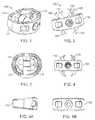
- FIGS. 1 and 2illustrate schematically one embodiment of a stand-alone interbody fixation system 100 .
- the stand-alone interbody fixation system 100is a pre-assembled multi-component design which integrates a fixation feature with an interbody spacer with no additional support required.
- the system 100is used in spinal fusion surgeries including, but not limited to Anterior Lumbar Interbody Fusion (ALIF), Posterior Lumbar Interbody Fusion (PLIF), or Transforaminal Lumbar Interbody Fusion (TLIF), lateral and cervical procedures, wherein two or more vertebrae are joined or fused together for the treatment of spinal disorders such as spondylolisthesis, scoliosis, severe disc degeneration, or spinal fractures.
- ALIFAnterior Lumbar Interbody Fusion
- PLIFPosterior Lumbar Interbody Fusion
- TLIFTransforaminal Lumbar Interbody Fusion
- the system 100may be used in a variety of spinal procedures, including open procedures and minimally invasive surgery (MIS) procedures using low profile instrumentation which facilitates a less invasive approach through a smaller incision.
- MISminimally invasive surgery
- the unique design of the stand-alone interbody fixation system 100provides a solid fixation in all aspects (flexion, extension, torsion, rotation, migration).
- the system 100is configured to use a single instrument to distract, insert and deploy the system.
- the designallows for multiple footprint shapes, ranging from 20-40 mm in both length and width to ensure adequate contact with cortical rim.
- the designincludes a tapered leading portion that allows smooth insertion and deployment.
- the heightmay range from 8-20 mm, but other heights are also contemplated, depending on location. Lordosis ranging from 0-20 degrees to accommodate surgical needs.
- the system 100 discloseduses counter rotating blades 110 , 115 that provide 4 points of fixation with 2-10 mm of blade engagement.
- the blade lengthmay be increased or decreased to accommodate the cage height.
- the amount of exposed bladeis controlled across the various implant sizes.
- counter rotating bladesare disclosed, other embodiments may deploy the blades rotating in the same direction. Secure deployment and engagement of blades with positive feedback when blades deployed and locked. Internal lock prevents accidental deployment and positive tangible feedback to surgeon when the blades are fully deployed.
- the bladesare securely held in place and some embodiments may include elements to prevent over-deployment. In some embodiments, the ability to reverse deployment and remove or reposition implant may be desirable.
- the unique blade shapeallows adequate space to pack bone graft before insertion. There are also access ports in the interbody spacer or cage to allow additional bone graft to be added after insertion/deployment. Some embodiments of the blade shape geometry may also pull the endplates together when deployed.
- the stand-alone interbody fixation system 100includes a cage 105 , an anterior fixation blade 110 and a posterior fixation blade 115 .
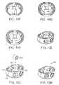
- FIG. 1is a perspective view showing the anterior 110 and posterior 115 blades within the cage 105 in a delivery position and
- FIG. 2is a perspective view showing the anterior 110 and posterior 115 blades in the deployed position.
- FIG. 3is a top view showing an embodiment in which the curved anterior 110 and posterior 115 blades are designed to follow shape of the interior of the cage 105 resulting in axial windows 130 that may be used for packing of bone graft material within to expedite the fusion of the cage in the spinal column.
- FIG. 4is a view looking posteriorly showing the cage 105 and the anterior 110 and posterior 115 blades in the deployed position.
- FIG. 5Ais a side view and
- FIG. 5Bis a front view of the cage 105 and the anterior 110 and posterior 115 blades in the stowed position.
- the stand-alone interbody fixation system 100is inserted and fixated from an anterior approach so that posterior muscular structures are preserved and surgical morbidity associated with 360° is eliminated.
- the anterior fixation blade 110rotates in a clockwise rotation 120 and the posterior fixation blade 115 rotates in a counterclockwise rotation 125 , shown in FIG. 2 , biting into the vertebral end plates (not shown). While embodiments below are described primarily in the context of two counter rotating blades, other number of blades and rotations are also contemplated.
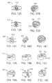
- FIGS. 6A-6Cshow some of the assembly features of the stand-alone interbody fixation system 100 .
- FIG. 6Ais a top view showing the anterior 110 and posterior 115 blades positioned for insertion with the axial window 130 between for placement of bone graft or other types of bone growth materials or biologics (not shown).
- FIG. 6Bis a side view showing that when the anterior 110 and posterior 115 blades in the stowed or rest position they are under the boundaries or surfaces of the cage 105 geometry. This allows the system 100 to be inserted between the end plates of adjacent vertebrae without anterior 110 and posterior 115 blades contacting the end plates.
- FIG. 6Cis a perspective view of the system showing a stop 240 on the cage 105 that the anterior 110 and posterior 115 blades may contact during deployment to prevent the blades from exceeding maximum deployment.
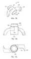
- FIGS. 7A-7Cshow one embodiment of an anterior fixation blade 110 that includes curved blades designed to penetrate the end plates of adjacent vertebrae.
- the curved bladesmay have a smooth curve or may be a series of straight sections. Using curved blades maximizes graft volume and minimizes graft displacement during deployment.
- the anterior fixation blade 110may be constructed of titanium, a titanium alloy, polyetherketoneketone (PEEK), or any other biologically acceptable materials that would engage the spine plate and provide a rigid structure.
- the anterior fixation blade 110may be constructed using one material or a combination of the materials.
- the anterior fixation blade 110includes blade tips 135 that are designed to penetrate bone with a sharp tip feature and continue to a leading edge or cutting edge 140 , similar to a sickle.
- the blade tips 135 positioned at the outer perimeter of an anterior fixation blade 110 diameterfacilitate immediate bone engagement at initial deployment.
- the bladesare attached to an axial alignment boss 145 .
- the bladesinclude cutting edge that spans the entire length of the blade from the boss to the tip for all sizes.
- the axial alignment boss 145has a first end 150 and a second end 155 .
- the first end 150includes a cylindrical rotating alignment feature that includes one or more blade resistance/securing/locking feature 160 that couples to the cage 105 (discussed below).
- the first end 150further includes a drive mechanism 152 or recess configured to engage a deployment instrument for rotating the anterior fixation blade 110 between a closed and open position.
- the drive mechanismmay be a Hex, Hex-a-lobe, spline, double hex, Bristol, polydrive, torq-set, square, slotted, Phillips, etc.
- the second end 155 of the boss 145includes an opening 165 configured to interact with the posterior fixation blade 115 and also allows insertion of the deployment instrument for actuation of the posterior fixation blade 115 .
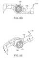
- FIGS. 8A-8Eshow one embodiment of a posterior fixation blade 115 that includes curved blades designed to penetrate the end plates of adjacent vertebrae. Smooth curved or a series of straight sections that form the curved blades maximize graft volume and minimize graft displacement during deployment.
- the posterior fixation blade 115may be constructed of titanium, a titanium alloy, polyetherketoneketone (PEEK), or any other biologically acceptable inert materials that would provide a rigid structure.
- the posterior fixation blade 115may also be constructed with a combination of the materials.
- the posterior fixation blade 115includes blade tips 170 that are designed to penetrate with a sharp tip feature and continue to a sharp leading edge or cutting edge 175 , similar to a sickle.
- the blade tips 170 at the outer perimeter of the diameterfacilitate immediate bone engagement at initial deployment.
- the bladesare attached to an axial alignment boss 180 .
- the bladesinclude cutting edge that spans the entire length of the blade from the boss to the tip for all sizes.
- the axial alignment boss 180has a first end 185 and a second end 190 .
- the first end 185is designed to slidably fit within the opening 165 of the anterior fixation blade 110 .
- the first end 185further includes a drive mechanism 187 or recess for rotating the blade between a closed and open position.
- the drive mechanismmay be a Hex, Hex-a-lobe, spline, double hex, Bristol, polydrive, torq-set, square, slotted, Phillips, etc.
- the second end 190includes a cylindrical rotating alignment feature that includes one or more blade resistance/securing/locking feature 195 configured to couple with the cage 105 .
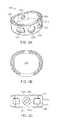
- FIGS. 9A-9Fshow different views and features of the cage 105 .
- the cage 105may be made of a rigid construction and preferably provided in several different sizes and shapes to fill differently sized evacuated spaces in differently sized individuals.
- the cage 105has an interior opening 200 for storage of the blades 110 , 115 .
- the curves shape of the blades 110 , 115allow packing of bone graft material (see FIG. 3 ).
- the cage 105may be constructed of a radiolucent material, such as polyetherketoneketone (PEEK), a commercially pure titanium, a titanium alloy or any other biologically acceptable inert materials that would provide the cage with a rigid structure.
- PEEKpolyetherketoneketone
- the cage 105is annular in configuration having an upper surface 205 and an opposed lower surface 210 configured to engage superiorly and inferiorly the end plates of adjacent vertebrae, and an annular side wall 215 around the hollow interior opening 200 .
- the annular side wall 215may have varying height, length, and thickness, and may include lordotic angle for better anatomical fit.
- a plurality of outwardly projecting sharp raised ridges/teeth/striations 220are formed on the surfaces 205 , 210 for biting into and gripping the vertebral end plates (not shown).
- the ridges 220may have a variable thickness, height, and width as well as an angle with respect to surfaces.
- the ridges 220may be disposed at slightly offset angles with respect to each other or, alternatively with respect to the ridges on different portions of the cage, to reduce the possibility of the ridges sliding in any direction along the end plates and to prevent rotation of the cage on the end plate.
- the figuresshow the ridges 220 on one side or portion of the surface 205 are all in parallel alignment, but misaligned with the ridges on the other side or portion. While it may be preferable that the ridges 220 are identical in configuration on the upper and lower surfaces, in some embodiments, the ridges or teeth different or have a different pattern for each surface.
- a plurality of openings 225 , 230are disposed in the side wall 215 of the cage 105 .
- Opening 225 ais configured to receive or engage end 150 of fixation blade 110 and opening 225 b is configured to receive or engage end 190 of fixation blade 115 .
- Other openings 230 spaced about the cagemay be configured to receive or engage an insertion tool or blade activation tool (not shown), or used to pack bone or other suitable bone graft material.
- Openings 225 a , 225 bare generally circular in shape and include blade resistance/locking features 235 a , 235 b to hold blades in one or more positions.
- These features 235 a , 235 bmay include grooves, notches or dimples that couple or interact with ridges, tabs or bumps 160 , 195 on blades 110 , 115 .
- bumps 160interact with one of the grooves 235 a .
- the bumps 160may move from one set of grooves 235 a in a stored position to another set of grooves 235 a in the deployed position, to form a locking mechanism.
- bumps 195interact with one of the grooves 235 b .
- Openings 230may be generally rectangular in shape to accommodate an insertion tool or blade activation tool having a center blade activation portion disposed between a pair of prongs, so that the tool can grip the openings 230 of the cage and/or rotate the blades.
- a blade stopping feature 240may also be used to contact the blades and prevent the blades from rotating more then desired angle.
- FIGS. 10A-10Hshow one example of an assembly method for system 100 .
- the anterior fixation blade 110 and posterior fixation blade 115are aligned ( FIG. 10A ) and the first end 185 of the posterior fixation blade 115 is inserted into the opening 160 near the second end 155 of the anterior fixation blade 110 .
- the distance between the first end 150 of the anterior fixation blade 110 and the second end 190 of the posterior fixation blade 115is less than an interior distance between the first opening 225 a and second opening 225 b of the cage 105 ( FIG. 10B ).
- the blades 110 , 115may then be moved or extended in opposite directions until the first end 150 of the anterior fixation blade 110 is inserted into the first opening 225 a and the second end 190 of the posterior fixation blade 115 is inserted into the second opening 225 b and the blades are rotated to the stored position ( FIGS. 10E-10I ).
- a C-clip 245is slid over the boss 180 of the posterior fixation blade 115 ( FIG. 10J ) to keep the ends of the anterior and posterior fixation blades 110 , 115 within the openings 225 a , 225 b forming the system 100 ( FIG. 10K ).
- FIG. 11is an exploded view showing another embodiment of a stand-alone interbody fixation system 300 , having a cage 305 , an anterior fixation blade 310 and a posterior fixation blade 315 .
- the cage 305may be similar to cage 105 and may include one or more of the features disclosed above for cage 105 .
- the anterior and posterior fixation blades 310 , 315may include one or more of the features disclosed above for blades 110 , 115 . In the embodiment shown, the anterior and posterior fixation blades 310 , 315 are straight.
- the cage 305includes a first opening 325 a with an open top portion configured to couple with a first end 350 of the anterior fixation blade 310 and a second opening 325 b configured to couple with a second end 390 of the posterior blade 315 .
- a first end 380 of the posterior fixation blade 315is coupled with a second end 355 of the anterior fixation blade 310 .
- the joined fixation blades 310 , 315are then advanced toward the cage 305 and the second end 390 of the posterior fixation blade 315 is inserted into the second opening 325 b .
- the first end 350 of the anterior fixation blade 310is inserted into the open top portion of the first opening 325 a , snapping in place.
- the first opening 325 amay have spring like side portions that hold the first end 350 of the anterior fixation blade 310 in place.
- the ends 350 , 390 of the bladesmay also include ridges, tabs or bumps that engage or couple with grooves, notches or dimples in openings 325 a and 325 b , similar to those disclosed above for system 100 .
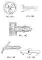
- FIGS. 12A-16Cshow different embodiments of stand-alone interbody fixation systems which integrates a fixation feature with an interbody spacer with no additional support required.
- One or more of the elements and feature disclosed above for the stand-alone interbody fixation system 100 and 300may be incorporated into the systems below.
- FIGS. 12A and 12Bshow one embodiment of a stand-alone single anterior blade interbody fixation system 400 having one fixation blade 410 , with multiple axial graft windows 430 and transverse inner walls.
- the fixation blade 410is a true s-shaped blade positioned toward a front portion of the implant and may used for anterior fixation (a reversed design with the blade toward the back portion may be for posterior fixation) and the transverse inner walls create a robust cage with center struts and allow axial graft windows.
- FIGS. 13A and 13Bshow another embodiment of a stand-alone double blade interbody fixation system 500 having two fixation blades 510 , 515 , central graft window 530 and transverse inner walls.
- This embodimentincludes fixation blades that are true s-shaped blades positioned on opposite sides of the central graft window 530 for anterior and posterior fixation, and the transverse inner walls create a robust cage with center struts and allow a larger axial graft window.
- FIGS. 14A and 14Bshow another embodiment of a stand-alone single anterior blade interbody fixation system 600 having a single blade 610 with multiple cutting edges, posterior graft window and transverse inner wall.
- the multiple cutting edges of the fixation bladeare true s-shaped with sharp tips used for anterior to posterior fixation, including midline fixation.
- the transverse inner wallcreate a robust cage and allows posterior graft window.
- FIGS. 15A-15Cshow another embodiment of a stand-alone interbody fixation system 700 having two fixation blades 710 , 715 , with multiple cutting edges and graft window.
- This embodimentincludes fixation blades that are true s-shaped blades for fixation, and superior anterior and posterior fixation.
- FIGS. 16A-16Cshow another embodiment of a stand-alone interbody fixation system 800 two fixation blades 810 , 815 with multiple cutting edges and graft window. This embodiment includes fixation blades with the maximum achievable blade length and simple blade to cage assembly.
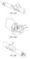
- FIGS. 17A-17Dare views showing other embodiments of anterior and/or posterior blades suitable for use in the embodiments disclosed above.
- the bladesmay be curved blades having a smooth curve or may be a series of straight sections or both.
- the bladesmay also vary in thickness in both height and width.
- the deployment instrumentwill have two concentric counter rotating shafts.
- the counter-rotationcan be achieved with a series gears (shown in FIGS. 18A-18C ) or with two levers (shown in FIGS. 19A-19B ).
- the tip of the instrumentmay have an interference fit to fixate to the implant.
- the implant holderwill be cannulated to allow the blade deployment instrument to pass through.
- the implant inserter/distractorwill also be cannulated to allow the deployment shafts to pass through.
- FIGS. 20A-20Cshow another embodiment of a deployment instrument interacting with the cage 105 . Handles are used to deploy the blades (not shown).
Landscapes
- Health & Medical Sciences (AREA)
- Engineering & Computer Science (AREA)
- Biomedical Technology (AREA)
- Orthopedic Medicine & Surgery (AREA)
- Transplantation (AREA)
- Neurology (AREA)
- Oral & Maxillofacial Surgery (AREA)
- Cardiology (AREA)
- Heart & Thoracic Surgery (AREA)
- Vascular Medicine (AREA)
- Life Sciences & Earth Sciences (AREA)
- Animal Behavior & Ethology (AREA)
- General Health & Medical Sciences (AREA)
- Public Health (AREA)
- Veterinary Medicine (AREA)
- Physical Education & Sports Medicine (AREA)
- Prostheses (AREA)
Abstract
Description
Claims (18)
Priority Applications (3)
| Application Number | Priority Date | Filing Date | Title |
|---|---|---|---|
| US12/852,033US8328870B2 (en) | 2009-08-06 | 2010-08-06 | Stand-alone interbody fixation system |
| US13/633,301US8979933B2 (en) | 2009-08-06 | 2012-10-02 | Stand-alone interbody fixation system |
| US13/666,099US10441433B2 (en) | 2009-08-06 | 2012-11-01 | Stand-alone interbody fixation system |
Applications Claiming Priority (2)
| Application Number | Priority Date | Filing Date | Title |
|---|---|---|---|
| US23196709P | 2009-08-06 | 2009-08-06 | |
| US12/852,033US8328870B2 (en) | 2009-08-06 | 2010-08-06 | Stand-alone interbody fixation system |
Related Child Applications (2)
| Application Number | Title | Priority Date | Filing Date |
|---|---|---|---|
| US13/633,301Continuation-In-PartUS8979933B2 (en) | 2009-08-06 | 2012-10-02 | Stand-alone interbody fixation system |
| US13/666,099ContinuationUS10441433B2 (en) | 2009-08-06 | 2012-11-01 | Stand-alone interbody fixation system |
Publications (2)
| Publication Number | Publication Date |
|---|---|
| US20110035007A1 US20110035007A1 (en) | 2011-02-10 |
| US8328870B2true US8328870B2 (en) | 2012-12-11 |
Family
ID=43535411
Family Applications (1)
| Application Number | Title | Priority Date | Filing Date |
|---|---|---|---|
| US12/852,033Expired - Fee RelatedUS8328870B2 (en) | 2009-08-06 | 2010-08-06 | Stand-alone interbody fixation system |
Country Status (1)
| Country | Link |
|---|---|
| US (1) | US8328870B2 (en) |
Cited By (19)
| Publication number | Priority date | Publication date | Assignee | Title |
|---|---|---|---|---|
| US8900310B2 (en)* | 2012-04-05 | 2014-12-02 | Zimmer Spine, Inc. | Interbody spacer |
| US20150100127A1 (en)* | 2011-07-14 | 2015-04-09 | Tria Spine Medikal Ltd. Sti. | Fixation System for Spinal Cages |
| US9636232B2 (en) | 2014-10-27 | 2017-05-02 | Seth L. Neubardt | Harvesting bone graft material for use in spinal and other bone fusion surgeries |
| US9693876B1 (en) | 2012-03-30 | 2017-07-04 | Ali H. MESIWALA | Spinal fusion implant and related methods |
| US9707100B2 (en) | 2015-06-25 | 2017-07-18 | Institute for Musculoskeletal Science and Education, Ltd. | Interbody fusion device and system for implantation |
| US9833332B2 (en) | 2014-10-27 | 2017-12-05 | Seth L Neubardt | Harvesting bone graft material for use in spinal and other bone fusion surgeries |
| US9937055B1 (en) | 2016-11-28 | 2018-04-10 | Spine Wave, Inc. | Scoring implant trial and implant inserter for spinal fusion system |
| US9968464B2 (en) | 2014-01-17 | 2018-05-15 | Spine Wave, Inc. | Spinal fusion system |
| US9987142B2 (en) | 2012-08-31 | 2018-06-05 | Institute for Musculoskeletal Science and Education, Ltd. | Fixation devices for anterior lumbar or cervical interbody fusion |
| WO2019018013A1 (en)* | 2017-07-18 | 2019-01-24 | Frank Castro | Spinal implant system |
| US10307265B2 (en) | 2016-10-18 | 2019-06-04 | Institute for Musculoskeletal Science and Education, Ltd. | Implant with deployable blades |
| US10405992B2 (en) | 2016-10-25 | 2019-09-10 | Institute for Musculoskeletal Science and Education, Ltd. | Spinal fusion implant |
| US10449060B2 (en) | 2016-10-25 | 2019-10-22 | Institute for Musculoskeletal Science and Education, Ltd. | Spinal fusion implant |
| US10849758B2 (en) | 2018-08-22 | 2020-12-01 | Institute for Musculoskeletal Science and Education, Ltd. | Spinal fusion implant |
| US10888434B2 (en) | 2017-10-05 | 2021-01-12 | Spine Wave, Inc. | Modular scoring trial for anterior cervical cage |
| WO2021162758A1 (en)* | 2020-02-12 | 2021-08-19 | Blue Sky Technologies, LLC | Surgical fastener |
| US20220110760A1 (en)* | 2015-06-25 | 2022-04-14 | Twist Technologies Sàrl | Interbody cage and method of insertion |
| US11471299B2 (en) | 2020-07-30 | 2022-10-18 | NovAppoach Spine LLC | Interbody cage device and methods of use |
| US20240335292A1 (en)* | 2016-06-23 | 2024-10-10 | Frank H. Boehm, Jr. | Minimally invasive direct posterior sacroiliac joint fusion |
Families Citing this family (57)
| Publication number | Priority date | Publication date | Assignee | Title |
|---|---|---|---|---|
| FR2897259B1 (en) | 2006-02-15 | 2008-05-09 | Ldr Medical Soc Par Actions Si | INTERSOMATIC TRANSFORAMINAL CAGE WITH INTERBREBAL FUSION GRAFT AND CAGE IMPLANTATION INSTRUMENT |
| FR2824261B1 (en) | 2001-05-04 | 2004-05-28 | Ldr Medical | INTERVERTEBRAL DISC PROSTHESIS AND IMPLEMENTATION METHOD AND TOOLS |
| FR2827156B1 (en) | 2001-07-13 | 2003-11-14 | Ldr Medical | VERTEBRAL CAGE DEVICE WITH MODULAR FASTENING |
| FR2846550B1 (en) | 2002-11-05 | 2006-01-13 | Ldr Medical | INTERVERTEBRAL DISC PROSTHESIS |
| FR2865629B1 (en) | 2004-02-04 | 2007-01-26 | Ldr Medical | INTERVERTEBRAL DISC PROSTHESIS |
| EP2113227B1 (en) | 2004-02-04 | 2015-07-29 | LDR Medical | Intervertebral disc prosthesis |
| FR2869528B1 (en) | 2004-04-28 | 2007-02-02 | Ldr Medical | INTERVERTEBRAL DISC PROSTHESIS |
| US8597360B2 (en) | 2004-11-03 | 2013-12-03 | Neuropro Technologies, Inc. | Bone fusion device |
| FR2879436B1 (en) | 2004-12-22 | 2007-03-09 | Ldr Medical | INTERVERTEBRAL DISC PROSTHESIS |
| FR2891135B1 (en) | 2005-09-23 | 2008-09-12 | Ldr Medical Sarl | INTERVERTEBRAL DISC PROSTHESIS |
| FR2893838B1 (en) | 2005-11-30 | 2008-08-08 | Ldr Medical Soc Par Actions Si | PROSTHESIS OF INTERVERTEBRAL DISC AND INSTRUMENTATION OF INSERTION OF THE PROSTHESIS BETWEEN VERTEBRATES |
| US8465546B2 (en)* | 2007-02-16 | 2013-06-18 | Ldr Medical | Intervertebral disc prosthesis insertion assemblies |
| FR2916956B1 (en) | 2007-06-08 | 2012-12-14 | Ldr Medical | INTERSOMATIC CAGE, INTERVERTEBRAL PROSTHESIS, ANCHORING DEVICE AND IMPLANTATION INSTRUMENTATION |
| US8540769B2 (en)* | 2007-11-28 | 2013-09-24 | Pioneer Surgical Technology, Inc. | Device for securing an implant to tissue |
| US10045860B2 (en)* | 2008-12-19 | 2018-08-14 | Amicus Design Group, Llc | Interbody vertebral prosthetic device with self-deploying screws |
| US8968405B2 (en)* | 2009-01-20 | 2015-03-03 | Incite Innovation Llc | Interbody fusion device and method of operation |
| US10441433B2 (en)* | 2009-08-06 | 2019-10-15 | Alphatec Spine, Inc. | Stand-alone interbody fixation system |
| CN105326585B (en) | 2009-09-17 | 2018-12-11 | Ldr控股公司 | Intervertebral implant with extensible bone anchoring element |
| JP2013509959A (en)* | 2009-11-06 | 2013-03-21 | ジンテス ゲゼルシャフト ミット ベシュレンクテル ハフツング | Minimally invasive interspinous spacer implant and method |
| WO2011080535A1 (en) | 2009-12-31 | 2011-07-07 | Lrd Medical | Anchoring device, intervertebral implant and implantation instrument |
| US9913726B2 (en)* | 2010-02-24 | 2018-03-13 | Globus Medical, Inc. | Expandable intervertebral spacer and method of posterior insertion thereof |
| WO2012148838A1 (en) | 2011-04-26 | 2012-11-01 | Alphatec Spine, Inc. | Stand alone interbody fixation system |
| PL218347B1 (en)* | 2011-05-12 | 2014-11-28 | Lfc Spółka Z Ograniczoną Odpowiedzialnością | Intervertebral implant for positioning of adjacent vertebrae |
| WO2013023096A1 (en) | 2011-08-09 | 2013-02-14 | Neuropro Technologies, Inc. | Bone fusion device, system and method |
| US9358123B2 (en)* | 2011-08-09 | 2016-06-07 | Neuropro Spinal Jaxx, Inc. | Bone fusion device, apparatus and method |
| US10420654B2 (en) | 2011-08-09 | 2019-09-24 | Neuropro Technologies, Inc. | Bone fusion device, system and method |
| US20140058446A1 (en)* | 2011-09-28 | 2014-02-27 | Avi Bernstein | Spinal implant system |
| US8460388B2 (en)* | 2011-10-28 | 2013-06-11 | Incite Innovation Llc | Spinal interbody device |
| US8795167B2 (en) | 2011-11-15 | 2014-08-05 | Baxano Surgical, Inc. | Spinal therapy lateral approach access instruments |
| US9408613B2 (en) | 2011-12-13 | 2016-08-09 | Biomet Manufacturing, Llc | Glenoid reamer |
| FR2987256B1 (en) | 2012-02-24 | 2014-08-08 | Ldr Medical | ANCHORING DEVICE FOR INTERVERTEBRAL IMPLANT, INTERVERTEBRAL IMPLANT AND IMPLANTATION INSTRUMENTATION |
| ES2770824T3 (en)* | 2012-03-19 | 2020-07-03 | Amicus Design Group Llc | Intervertebral fusion prosthetic and orthopedic device with self-deploying anchors |
| US9566165B2 (en) | 2012-03-19 | 2017-02-14 | Amicus Design Group, Llc | Interbody vertebral prosthetic and orthopedic fusion device with self-deploying anchors |
| WO2013149134A2 (en)* | 2012-03-30 | 2013-10-03 | Olympus Biotech Corporation | Alif spinal implant |
| US9532883B2 (en) | 2012-04-13 | 2017-01-03 | Neuropro Technologies, Inc. | Bone fusion device |
| EP2716261A1 (en)* | 2012-10-02 | 2014-04-09 | Titan Spine, LLC | Implants with self-deploying anchors |
| US20140172104A1 (en)* | 2012-12-18 | 2014-06-19 | Alphatec Spine, Inc. | Instrument for insertion and deployment of an implant |
| CA2906531C (en) | 2013-03-15 | 2020-10-06 | Neuropro Technologies, Inc. | Bodiless bone fusion device, apparatus and method |
| WO2014145527A2 (en) | 2013-03-15 | 2014-09-18 | Lifenet Health | Medical implant for fixation and integration with hard tissue |
| US9549822B2 (en)* | 2013-05-03 | 2017-01-24 | DePuy Synthes Products, Inc. | Vertebral body replacement or fusion device |
| FR3005569B1 (en) | 2013-05-16 | 2021-09-03 | Ldr Medical | VERTEBRAL IMPLANT, VERTEBRAL IMPLANT FIXATION DEVICE AND IMPLANTATION INSTRUMENTATION |
| US9351847B2 (en)* | 2013-08-22 | 2016-05-31 | Globus Medical, Inc. | Interbody fusion devices with self-affixing mechanisms |
| FR3016793B1 (en) | 2014-01-30 | 2021-05-07 | Ldr Medical | ANCHORING DEVICE FOR SPINAL IMPLANT, SPINAL IMPLANT AND IMPLANTATION INSTRUMENTATION |
| US9642723B2 (en)* | 2014-02-27 | 2017-05-09 | Alphatec Spine, Inc. | Spinal implants and insertion instruments |
| FR3020756B1 (en) | 2014-05-06 | 2022-03-11 | Ldr Medical | VERTEBRAL IMPLANT, VERTEBRAL IMPLANT FIXATION DEVICE AND IMPLANT INSTRUMENTATION |
| US20160045326A1 (en)* | 2014-08-18 | 2016-02-18 | Eric Hansen | Interbody spacer system |
| US10363143B2 (en) | 2015-04-16 | 2019-07-30 | Seth L. Neubardt | Harvesting bone graft material for use in spinal and other bone fusion surgeries |
| US10111760B2 (en) | 2017-01-18 | 2018-10-30 | Neuropro Technologies, Inc. | Bone fusion system, device and method including a measuring mechanism |
| US10729560B2 (en) | 2017-01-18 | 2020-08-04 | Neuropro Technologies, Inc. | Bone fusion system, device and method including an insertion instrument |
| US10213321B2 (en) | 2017-01-18 | 2019-02-26 | Neuropro Technologies, Inc. | Bone fusion system, device and method including delivery apparatus |
| US10973657B2 (en)* | 2017-01-18 | 2021-04-13 | Neuropro Technologies, Inc. | Bone fusion surgical system and method |
| FR3092246B1 (en)* | 2019-02-04 | 2023-03-24 | Razian Hassan | Interosseous cage |
| WO2020242551A1 (en)* | 2019-05-24 | 2020-12-03 | Blue Sky Technologies, LLC | Joint implant |
| EP3943049B1 (en)* | 2020-07-21 | 2023-05-24 | Razian, Hassan | Interosseous cage |
| FR3136960B1 (en)* | 2022-06-28 | 2024-05-24 | Hassan Razian | Intervertebral cage |
| FR3136959B1 (en)* | 2022-06-28 | 2024-07-26 | Hassan Razian | Intervertebral cage |
| FR3150707A1 (en)* | 2023-07-03 | 2025-01-10 | Hassan Razian | Blade cage suitable for implantation between two vertebrae |
Citations (10)
| Publication number | Priority date | Publication date | Assignee | Title |
|---|---|---|---|---|
| US5683394A (en)* | 1995-09-29 | 1997-11-04 | Advanced Spine Fixation Systems, Inc. | Fusion mass constrainer |
| US6527803B1 (en)* | 1998-06-23 | 2003-03-04 | Dimso (Distribution Medicale Du Sud-Ouest) | Intersomatic spine implant having anchoring elements |
| US6670096B2 (en)* | 2000-12-01 | 2003-12-30 | Fuji Photo Film Co., Ltd. | Base material for lithographic printing plate and lithographic printing plate using the same |
| US6770096B2 (en)* | 1999-07-01 | 2004-08-03 | Spinevision S.A. | Interbody spinal stabilization cage and spinal stabilization method |
| US20070270961A1 (en)* | 2006-04-25 | 2007-11-22 | Sdgi Holdings, Inc. | Spinal implant with deployable and retractable barbs |
| US20090099601A1 (en)* | 2007-10-11 | 2009-04-16 | International Spinal Innovations, Llc | Minimally invasive lateral intervertbral fixation system, device and method |
| US20090164020A1 (en)* | 2007-11-28 | 2009-06-25 | Pioneer Surgical Technology, Inc. | Device for Securing an Implant to Tissue |
| US7594932B2 (en)* | 2005-12-29 | 2009-09-29 | International Spinal Innovations, Llc | Apparatus for anterior intervertebral spinal fixation and fusion |
| US20100106191A1 (en)* | 2008-08-27 | 2010-04-29 | Yue James J | Conical interspinous apparatus and a method of performing interspinous distraction |
| US20110054616A1 (en)* | 2009-02-19 | 2011-03-03 | Aflatoon Kamran | Open body box form interbody fusion cage |
- 2010
- 2010-08-06USUS12/852,033patent/US8328870B2/ennot_activeExpired - Fee Related
Patent Citations (10)
| Publication number | Priority date | Publication date | Assignee | Title |
|---|---|---|---|---|
| US5683394A (en)* | 1995-09-29 | 1997-11-04 | Advanced Spine Fixation Systems, Inc. | Fusion mass constrainer |
| US6527803B1 (en)* | 1998-06-23 | 2003-03-04 | Dimso (Distribution Medicale Du Sud-Ouest) | Intersomatic spine implant having anchoring elements |
| US6770096B2 (en)* | 1999-07-01 | 2004-08-03 | Spinevision S.A. | Interbody spinal stabilization cage and spinal stabilization method |
| US6670096B2 (en)* | 2000-12-01 | 2003-12-30 | Fuji Photo Film Co., Ltd. | Base material for lithographic printing plate and lithographic printing plate using the same |
| US7594932B2 (en)* | 2005-12-29 | 2009-09-29 | International Spinal Innovations, Llc | Apparatus for anterior intervertebral spinal fixation and fusion |
| US20070270961A1 (en)* | 2006-04-25 | 2007-11-22 | Sdgi Holdings, Inc. | Spinal implant with deployable and retractable barbs |
| US20090099601A1 (en)* | 2007-10-11 | 2009-04-16 | International Spinal Innovations, Llc | Minimally invasive lateral intervertbral fixation system, device and method |
| US20090164020A1 (en)* | 2007-11-28 | 2009-06-25 | Pioneer Surgical Technology, Inc. | Device for Securing an Implant to Tissue |
| US20100106191A1 (en)* | 2008-08-27 | 2010-04-29 | Yue James J | Conical interspinous apparatus and a method of performing interspinous distraction |
| US20110054616A1 (en)* | 2009-02-19 | 2011-03-03 | Aflatoon Kamran | Open body box form interbody fusion cage |
Cited By (39)
| Publication number | Priority date | Publication date | Assignee | Title |
|---|---|---|---|---|
| US9421112B2 (en)* | 2011-07-14 | 2016-08-23 | Tria Spine Meikal Ltd. Sti. | Fixation system for spinal cages |
| US20150100127A1 (en)* | 2011-07-14 | 2015-04-09 | Tria Spine Medikal Ltd. Sti. | Fixation System for Spinal Cages |
| US10238504B2 (en) | 2012-03-30 | 2019-03-26 | Ali H. MESIWALA | Spinal fusion implant and related methods |
| US9693876B1 (en) | 2012-03-30 | 2017-07-04 | Ali H. MESIWALA | Spinal fusion implant and related methods |
| US8900310B2 (en)* | 2012-04-05 | 2014-12-02 | Zimmer Spine, Inc. | Interbody spacer |
| US11013612B2 (en) | 2012-08-31 | 2021-05-25 | Institute for Musculoskeletal Science and Education, Ltd. | Fixation devices for anterior lumbar or cervical interbody fusion |
| US9987142B2 (en) | 2012-08-31 | 2018-06-05 | Institute for Musculoskeletal Science and Education, Ltd. | Fixation devices for anterior lumbar or cervical interbody fusion |
| US9968464B2 (en) | 2014-01-17 | 2018-05-15 | Spine Wave, Inc. | Spinal fusion system |
| US10219916B2 (en) | 2014-01-17 | 2019-03-05 | Spine Wave, Inc. | Method for fusing spinal vertebrae |
| US11051952B2 (en) | 2014-01-17 | 2021-07-06 | Spine Wave, Inc. | Spinal implant system |
| US9833332B2 (en) | 2014-10-27 | 2017-12-05 | Seth L Neubardt | Harvesting bone graft material for use in spinal and other bone fusion surgeries |
| US9636232B2 (en) | 2014-10-27 | 2017-05-02 | Seth L. Neubardt | Harvesting bone graft material for use in spinal and other bone fusion surgeries |
| US10307266B2 (en) | 2014-10-27 | 2019-06-04 | Seth L. Neubardt | Harvesting bone graft material for use in spinal and other fusion surgeries |
| US20220110760A1 (en)* | 2015-06-25 | 2022-04-14 | Twist Technologies Sàrl | Interbody cage and method of insertion |
| US9707100B2 (en) | 2015-06-25 | 2017-07-18 | Institute for Musculoskeletal Science and Education, Ltd. | Interbody fusion device and system for implantation |
| US20240335292A1 (en)* | 2016-06-23 | 2024-10-10 | Frank H. Boehm, Jr. | Minimally invasive direct posterior sacroiliac joint fusion |
| US11246716B2 (en) | 2016-10-18 | 2022-02-15 | Institute for Musculoskeletal Science and Education, Ltd. | Implant with deployable blades |
| US11877935B2 (en) | 2016-10-18 | 2024-01-23 | Camber Spine Technologies, LLC | Implant with deployable blades |
| US10307265B2 (en) | 2016-10-18 | 2019-06-04 | Institute for Musculoskeletal Science and Education, Ltd. | Implant with deployable blades |
| US12329656B2 (en) | 2016-10-18 | 2025-06-17 | Camber Spine Technologies, LLC | Implant with deployable blades |
| US10449060B2 (en) | 2016-10-25 | 2019-10-22 | Institute for Musculoskeletal Science and Education, Ltd. | Spinal fusion implant |
| US10405992B2 (en) | 2016-10-25 | 2019-09-10 | Institute for Musculoskeletal Science and Education, Ltd. | Spinal fusion implant |
| US11872143B2 (en) | 2016-10-25 | 2024-01-16 | Camber Spine Technologies, LLC | Spinal fusion implant |
| US11413157B2 (en) | 2016-10-25 | 2022-08-16 | Institute for Musculoskeletal Science and Education, Ltd. | Spinal fusion implant |
| US10603186B2 (en) | 2016-11-28 | 2020-03-31 | Spine Wave, Inc. | Spinal implant inserter assembly for use in spinal fusion |
| US9937055B1 (en) | 2016-11-28 | 2018-04-10 | Spine Wave, Inc. | Scoring implant trial and implant inserter for spinal fusion system |
| US10500060B2 (en) | 2016-11-28 | 2019-12-10 | Spine Wave, Inc. | Disc preparation instrument for use in spinal fusion |
| US10524925B2 (en) | 2016-11-28 | 2020-01-07 | Spine Wave, Inc. | Method for spinal fusion |
| US10932919B2 (en) | 2017-07-18 | 2021-03-02 | Blue Sky Technologies, LLC | Spinal implant system |
| WO2019018013A1 (en)* | 2017-07-18 | 2019-01-24 | Frank Castro | Spinal implant system |
| US10888435B2 (en) | 2017-10-05 | 2021-01-12 | Spine Wave, Inc. | Modular inserter for anterior cervical cage |
| US11813177B2 (en) | 2017-10-05 | 2023-11-14 | Spine Wave, Inc. | Spinal surgery kit comprising a plurality of modular inserter tips |
| US11819222B2 (en) | 2017-10-05 | 2023-11-21 | Spine Wave, Inc. | Depth stop instrument for use in spinal surgery |
| US10888434B2 (en) | 2017-10-05 | 2021-01-12 | Spine Wave, Inc. | Modular scoring trial for anterior cervical cage |
| US10849758B2 (en) | 2018-08-22 | 2020-12-01 | Institute for Musculoskeletal Science and Education, Ltd. | Spinal fusion implant |
| WO2021162758A1 (en)* | 2020-02-12 | 2021-08-19 | Blue Sky Technologies, LLC | Surgical fastener |
| US12127768B2 (en) | 2020-02-12 | 2024-10-29 | Blue Sky Technologies, LLC | Surgical fastener |
| US11471298B2 (en) | 2020-07-30 | 2022-10-18 | Novapproach Spine Llc | Interbody cage device and methods of use |
| US11471299B2 (en) | 2020-07-30 | 2022-10-18 | NovAppoach Spine LLC | Interbody cage device and methods of use |
Also Published As
| Publication number | Publication date |
|---|---|
| US20110035007A1 (en) | 2011-02-10 |
Similar Documents
| Publication | Publication Date | Title |
|---|---|---|
| US8328870B2 (en) | Stand-alone interbody fixation system | |
| US10441433B2 (en) | Stand-alone interbody fixation system | |
| US8979933B2 (en) | Stand-alone interbody fixation system | |
| US11696838B2 (en) | Systems and methods for inserting an expandable intervertebral device | |
| EP3225214B1 (en) | Stand alone interbody fixation system | |
| EP3068347B1 (en) | Expandable spinal implant | |
| EP2967659B1 (en) | Bodiless bone fusion device | |
| AU2009228030B2 (en) | Expandable cage with locking device | |
| US8496706B2 (en) | Bone cage with components for controlled expansion | |
| US10383742B2 (en) | Intervertebral implant | |
| US20120029641A1 (en) | System and Methods for Spinal Fusion | |
| WO2014022779A1 (en) | Pivotal lateral cage and insertion tool | |
| WO2017051416A1 (en) | Obliquely aligned expanding cage |
Legal Events
| Date | Code | Title | Description |
|---|---|---|---|
| AS | Assignment | Owner name:ALPHATEC SPINE, INC., CALIFORNIA Free format text:ASSIGNMENT OF ASSIGNORS INTEREST;ASSIGNORS:PATEL, NIRALI;CHENG, YANG;TIMM, JENS PETER;AND OTHERS;SIGNING DATES FROM 20101029 TO 20101206;REEL/FRAME:025479/0763 | |
| AS | Assignment | Owner name:MIDCAP FINANCIAL, LLC, MARYLAND Free format text:SECURITY AGREEMENT;ASSIGNORS:ALPHATEC HOLDINGS, INC.;ALPHATEC SPINE, INC.;ALPHATEC INTERNATIONAL LLC;AND OTHERS;REEL/FRAME:028358/0193 Effective date:20120607 | |
| ZAAA | Notice of allowance and fees due | Free format text:ORIGINAL CODE: NOA | |
| ZAAB | Notice of allowance mailed | Free format text:ORIGINAL CODE: MN/=. | |
| STCF | Information on status: patent grant | Free format text:PATENTED CASE | |
| AS | Assignment | Owner name:DEERFIELD SPECIAL SITUATIONS FUND, L.P., NEW YORK Free format text:SECURITY INTEREST;ASSIGNORS:ALPHATEC HOLDINGS, INC.;ALPHATEC SPINE, INC.;ALPHATEC INTERNATIONAL LLC;AND OTHERS;REEL/FRAME:032551/0037 Effective date:20140317 Owner name:DEERFIELD SPECIAL SITUATIONS INTERNATIONAL MASTER Free format text:SECURITY INTEREST;ASSIGNORS:ALPHATEC HOLDINGS, INC.;ALPHATEC SPINE, INC.;ALPHATEC INTERNATIONAL LLC;AND OTHERS;REEL/FRAME:032551/0037 Effective date:20140317 Owner name:DEERFIELD PRIVATE DESIGN INTERNATIONAL II, L.P., N Free format text:SECURITY INTEREST;ASSIGNORS:ALPHATEC HOLDINGS, INC.;ALPHATEC SPINE, INC.;ALPHATEC INTERNATIONAL LLC;AND OTHERS;REEL/FRAME:032551/0037 Effective date:20140317 Owner name:DEERFIELD PRIVATE DESIGN FUND II, L.P., NEW YORK Free format text:SECURITY INTEREST;ASSIGNORS:ALPHATEC HOLDINGS, INC.;ALPHATEC SPINE, INC.;ALPHATEC INTERNATIONAL LLC;AND OTHERS;REEL/FRAME:032551/0037 Effective date:20140317 | |
| FPAY | Fee payment | Year of fee payment:4 | |
| AS | Assignment | Owner name:ALPHATEC HOLDINGS, INC., CALIFORNIA Free format text:RELEASE BY SECURED PARTY;ASSIGNORS:DEERFIELD PRIVATE DESIGN FUND II, L.P.;DEERFIELD PRIVATE DESIGN INTERNATIONAL II, L.P.;DEERFIELD SPECIAL SITUATIONS FUND, L.P.;AND OTHERS;REEL/FRAME:039950/0360 Effective date:20160901 Owner name:ALPHATEC INTERNATIONAL LLC, CALIFORNIA Free format text:RELEASE BY SECURED PARTY;ASSIGNORS:DEERFIELD PRIVATE DESIGN FUND II, L.P.;DEERFIELD PRIVATE DESIGN INTERNATIONAL II, L.P.;DEERFIELD SPECIAL SITUATIONS FUND, L.P.;AND OTHERS;REEL/FRAME:039950/0360 Effective date:20160901 Owner name:ALPHATEC SPINE, INC., CALIFORNIA Free format text:RELEASE BY SECURED PARTY;ASSIGNORS:DEERFIELD PRIVATE DESIGN FUND II, L.P.;DEERFIELD PRIVATE DESIGN INTERNATIONAL II, L.P.;DEERFIELD SPECIAL SITUATIONS FUND, L.P.;AND OTHERS;REEL/FRAME:039950/0360 Effective date:20160901 Owner name:ALPHATEC PACIFIC, INC., CALIFORNIA Free format text:RELEASE BY SECURED PARTY;ASSIGNORS:DEERFIELD PRIVATE DESIGN FUND II, L.P.;DEERFIELD PRIVATE DESIGN INTERNATIONAL II, L.P.;DEERFIELD SPECIAL SITUATIONS FUND, L.P.;AND OTHERS;REEL/FRAME:039950/0360 Effective date:20160901 | |
| AS | Assignment | Owner name:GLOBUS MEDICAL, INC., PENNSYLVANIA Free format text:INTELLECTUAL PROPERTY SECURITY AGREEMENT;ASSIGNORS:ALPHATEC HOLDINGS, INC.;ALPHATEC SPINE, INC.;REEL/FRAME:040108/0202 Effective date:20160901 | |
| AS | Assignment | Owner name:ALPHATEC SPINE, INC., CALIFORNIA Free format text:RELEASE BY SECURED PARTY;ASSIGNOR:GLOBUS MEDICAL, INC.;REEL/FRAME:047485/0084 Effective date:20181107 Owner name:ALPHATEC HOLDINGS, INC., CALIFORNIA Free format text:RELEASE BY SECURED PARTY;ASSIGNOR:GLOBUS MEDICAL, INC.;REEL/FRAME:047485/0084 Effective date:20181107 | |
| AS | Assignment | Owner name:SQUADRON MEDICAL FINANCE SOLUTIONS LLC, CONNECTICUT Free format text:SECURITY INTEREST;ASSIGNORS:ALPHATEC HOLDINGS, INC.;ALPHATEC SPINE, INC.;REEL/FRAME:047494/0562 Effective date:20181106 Owner name:SQUADRON MEDICAL FINANCE SOLUTIONS LLC, CONNECTICU Free format text:SECURITY INTEREST;ASSIGNORS:ALPHATEC HOLDINGS, INC.;ALPHATEC SPINE, INC.;REEL/FRAME:047494/0562 Effective date:20181106 | |
| MAFP | Maintenance fee payment | Free format text:PAYMENT OF MAINTENANCE FEE, 8TH YR, SMALL ENTITY (ORIGINAL EVENT CODE: M2552); ENTITY STATUS OF PATENT OWNER: SMALL ENTITY Year of fee payment:8 | |
| AS | Assignment | Owner name:ALPHATEC SPINE, INC., CALIFORNIA Free format text:RELEASE BY SECURED PARTY;ASSIGNOR:MIDCAP FUNDING IV TRUST;REEL/FRAME:052832/0132 Effective date:20200529 Owner name:ALPHATEC HOLDINGS, INC., DELAWARE Free format text:RELEASE BY SECURED PARTY;ASSIGNOR:MIDCAP FUNDING IV TRUST;REEL/FRAME:052832/0132 Effective date:20200529 | |
| AS | Assignment | Owner name:ALPHATEC HOLDINGS, INC., CALIFORNIA Free format text:RELEASE OF SECURITY INTEREST IN PATENT COLLATERAL AT REEL/FRAME NO. 47494/0562;ASSIGNOR:SQUADRON MEDICAL FINANCE SOLUTIONS LLC;REEL/FRAME:057177/0687 Effective date:20210804 Owner name:ALPHATEC SPINE, INC., CALIFORNIA Free format text:RELEASE OF SECURITY INTEREST IN PATENT COLLATERAL AT REEL/FRAME NO. 47494/0562;ASSIGNOR:SQUADRON MEDICAL FINANCE SOLUTIONS LLC;REEL/FRAME:057177/0687 Effective date:20210804 | |
| FEPP | Fee payment procedure | Free format text:ENTITY STATUS SET TO UNDISCOUNTED (ORIGINAL EVENT CODE: BIG.); ENTITY STATUS OF PATENT OWNER: LARGE ENTITY | |
| AS | Assignment | Owner name:ALPHATEC SPINE, INC., CALIFORNIA Free format text:RELEASE OF SECURITY INTEREST IN INTELLECTUAL PROPERTY AT REEL/FRAME NO. 028358/0193;ASSIGNOR:MIDCAP FUNDING IV TRUST, AS SUCCESSOR-IN-INTEREST TO MIDCAP FINANCIAL, LLC;REEL/FRAME:061553/0787 Effective date:20220922 Owner name:ALPHATEC HOLDINGS, INC., CALIFORNIA Free format text:RELEASE OF SECURITY INTEREST IN INTELLECTUAL PROPERTY AT REEL/FRAME NO. 028358/0193;ASSIGNOR:MIDCAP FUNDING IV TRUST, AS SUCCESSOR-IN-INTEREST TO MIDCAP FINANCIAL, LLC;REEL/FRAME:061553/0787 Effective date:20220922 | |
| AS | Assignment | Owner name:MIDCAP FUNDING IV TRUST, MARYLAND Free format text:SECURITY INTEREST;ASSIGNORS:ALPHATEC SPINE, INC.;SAFEOP SURGICAL, INC.;REEL/FRAME:062310/0001 Effective date:20230106 | |
| AS | Assignment | Owner name:WILMINGTON TRUST, NATIONAL ASSOCIATION, DELAWARE Free format text:SECURITY INTEREST;ASSIGNORS:ALPHATEC SPINE, INC.;SAFEOP SURGICAL, INC.;REEL/FRAME:062681/0020 Effective date:20230106 | |
| FEPP | Fee payment procedure | Free format text:MAINTENANCE FEE REMINDER MAILED (ORIGINAL EVENT CODE: REM.); ENTITY STATUS OF PATENT OWNER: LARGE ENTITY | |
| LAPS | Lapse for failure to pay maintenance fees | Free format text:PATENT EXPIRED FOR FAILURE TO PAY MAINTENANCE FEES (ORIGINAL EVENT CODE: EXP.); ENTITY STATUS OF PATENT OWNER: LARGE ENTITY | |
| STCH | Information on status: patent discontinuation | Free format text:PATENT EXPIRED DUE TO NONPAYMENT OF MAINTENANCE FEES UNDER 37 CFR 1.362 | |
| FP | Lapsed due to failure to pay maintenance fee | Effective date:20241211 |