US8328851B2 - Total disc replacement system and related methods - Google Patents
Total disc replacement system and related methodsDownload PDFInfo
- Publication number
- US8328851B2 US8328851B2US11/989,686US98968606AUS8328851B2US 8328851 B2US8328851 B2US 8328851B2US 98968606 AUS98968606 AUS 98968606AUS 8328851 B2US8328851 B2US 8328851B2
- Authority
- US
- United States
- Prior art keywords
- anchor plate
- lateral
- implant
- axis
- disc space
- Prior art date
- Legal status (The legal status is an assumption and is not a legal conclusion. Google has not performed a legal analysis and makes no representation as to the accuracy of the status listed.)
- Active, expires
Links
- 0CCC1C(CC)C=*C1Chemical compoundCCC1C(CC)C=*C10.000description1
Images


Classifications
- A—HUMAN NECESSITIES
- A61—MEDICAL OR VETERINARY SCIENCE; HYGIENE
- A61F—FILTERS IMPLANTABLE INTO BLOOD VESSELS; PROSTHESES; DEVICES PROVIDING PATENCY TO, OR PREVENTING COLLAPSING OF, TUBULAR STRUCTURES OF THE BODY, e.g. STENTS; ORTHOPAEDIC, NURSING OR CONTRACEPTIVE DEVICES; FOMENTATION; TREATMENT OR PROTECTION OF EYES OR EARS; BANDAGES, DRESSINGS OR ABSORBENT PADS; FIRST-AID KITS
- A61F2/00—Filters implantable into blood vessels; Prostheses, i.e. artificial substitutes or replacements for parts of the body; Appliances for connecting them with the body; Devices providing patency to, or preventing collapsing of, tubular structures of the body, e.g. stents
- A61F2/02—Prostheses implantable into the body
- A61F2/30—Joints
- A61F2/44—Joints for the spine, e.g. vertebrae, spinal discs
- A61F2/442—Intervertebral or spinal discs, e.g. resilient
- A61F2/4425—Intervertebral or spinal discs, e.g. resilient made of articulated components
- A—HUMAN NECESSITIES
- A61—MEDICAL OR VETERINARY SCIENCE; HYGIENE
- A61F—FILTERS IMPLANTABLE INTO BLOOD VESSELS; PROSTHESES; DEVICES PROVIDING PATENCY TO, OR PREVENTING COLLAPSING OF, TUBULAR STRUCTURES OF THE BODY, e.g. STENTS; ORTHOPAEDIC, NURSING OR CONTRACEPTIVE DEVICES; FOMENTATION; TREATMENT OR PROTECTION OF EYES OR EARS; BANDAGES, DRESSINGS OR ABSORBENT PADS; FIRST-AID KITS
- A61F2/00—Filters implantable into blood vessels; Prostheses, i.e. artificial substitutes or replacements for parts of the body; Appliances for connecting them with the body; Devices providing patency to, or preventing collapsing of, tubular structures of the body, e.g. stents
- A61F2/02—Prostheses implantable into the body
- A61F2/30—Joints
- A61F2/30767—Special external or bone-contacting surface, e.g. coating for improving bone ingrowth
- A61F2/30771—Special external or bone-contacting surface, e.g. coating for improving bone ingrowth applied in original prostheses, e.g. holes or grooves
- A—HUMAN NECESSITIES
- A61—MEDICAL OR VETERINARY SCIENCE; HYGIENE
- A61F—FILTERS IMPLANTABLE INTO BLOOD VESSELS; PROSTHESES; DEVICES PROVIDING PATENCY TO, OR PREVENTING COLLAPSING OF, TUBULAR STRUCTURES OF THE BODY, e.g. STENTS; ORTHOPAEDIC, NURSING OR CONTRACEPTIVE DEVICES; FOMENTATION; TREATMENT OR PROTECTION OF EYES OR EARS; BANDAGES, DRESSINGS OR ABSORBENT PADS; FIRST-AID KITS
- A61F2/00—Filters implantable into blood vessels; Prostheses, i.e. artificial substitutes or replacements for parts of the body; Appliances for connecting them with the body; Devices providing patency to, or preventing collapsing of, tubular structures of the body, e.g. stents
- A61F2/02—Prostheses implantable into the body
- A61F2/30—Joints
- A61F2/44—Joints for the spine, e.g. vertebrae, spinal discs
- A61F2/442—Intervertebral or spinal discs, e.g. resilient
- A—HUMAN NECESSITIES
- A61—MEDICAL OR VETERINARY SCIENCE; HYGIENE
- A61F—FILTERS IMPLANTABLE INTO BLOOD VESSELS; PROSTHESES; DEVICES PROVIDING PATENCY TO, OR PREVENTING COLLAPSING OF, TUBULAR STRUCTURES OF THE BODY, e.g. STENTS; ORTHOPAEDIC, NURSING OR CONTRACEPTIVE DEVICES; FOMENTATION; TREATMENT OR PROTECTION OF EYES OR EARS; BANDAGES, DRESSINGS OR ABSORBENT PADS; FIRST-AID KITS
- A61F2/00—Filters implantable into blood vessels; Prostheses, i.e. artificial substitutes or replacements for parts of the body; Appliances for connecting them with the body; Devices providing patency to, or preventing collapsing of, tubular structures of the body, e.g. stents
- A61F2/02—Prostheses implantable into the body
- A61F2/30—Joints
- A61F2/46—Special tools for implanting artificial joints
- A61F2/4603—Special tools for implanting artificial joints for insertion or extraction of endoprosthetic joints or of accessories thereof
- A61F2/4611—Special tools for implanting artificial joints for insertion or extraction of endoprosthetic joints or of accessories thereof of spinal prostheses
- A—HUMAN NECESSITIES
- A61—MEDICAL OR VETERINARY SCIENCE; HYGIENE
- A61F—FILTERS IMPLANTABLE INTO BLOOD VESSELS; PROSTHESES; DEVICES PROVIDING PATENCY TO, OR PREVENTING COLLAPSING OF, TUBULAR STRUCTURES OF THE BODY, e.g. STENTS; ORTHOPAEDIC, NURSING OR CONTRACEPTIVE DEVICES; FOMENTATION; TREATMENT OR PROTECTION OF EYES OR EARS; BANDAGES, DRESSINGS OR ABSORBENT PADS; FIRST-AID KITS
- A61F2/00—Filters implantable into blood vessels; Prostheses, i.e. artificial substitutes or replacements for parts of the body; Appliances for connecting them with the body; Devices providing patency to, or preventing collapsing of, tubular structures of the body, e.g. stents
- A61F2/02—Prostheses implantable into the body
- A61F2/30—Joints
- A61F2/46—Special tools for implanting artificial joints
- A61F2/4684—Trial or dummy prostheses
- A—HUMAN NECESSITIES
- A61—MEDICAL OR VETERINARY SCIENCE; HYGIENE
- A61F—FILTERS IMPLANTABLE INTO BLOOD VESSELS; PROSTHESES; DEVICES PROVIDING PATENCY TO, OR PREVENTING COLLAPSING OF, TUBULAR STRUCTURES OF THE BODY, e.g. STENTS; ORTHOPAEDIC, NURSING OR CONTRACEPTIVE DEVICES; FOMENTATION; TREATMENT OR PROTECTION OF EYES OR EARS; BANDAGES, DRESSINGS OR ABSORBENT PADS; FIRST-AID KITS
- A61F2/00—Filters implantable into blood vessels; Prostheses, i.e. artificial substitutes or replacements for parts of the body; Appliances for connecting them with the body; Devices providing patency to, or preventing collapsing of, tubular structures of the body, e.g. stents
- A61F2/02—Prostheses implantable into the body
- A61F2/30—Joints
- A61F2002/30001—Additional features of subject-matter classified in A61F2/28, A61F2/30 and subgroups thereof
- A61F2002/30316—The prosthesis having different structural features at different locations within the same prosthesis; Connections between prosthetic parts; Special structural features of bone or joint prostheses not otherwise provided for
- A61F2002/30329—Connections or couplings between prosthetic parts, e.g. between modular parts; Connecting elements
- A61F2002/30331—Connections or couplings between prosthetic parts, e.g. between modular parts; Connecting elements made by longitudinally pushing a protrusion into a complementarily-shaped recess, e.g. held by friction fit
- A61F2002/30362—Connections or couplings between prosthetic parts, e.g. between modular parts; Connecting elements made by longitudinally pushing a protrusion into a complementarily-shaped recess, e.g. held by friction fit with possibility of relative movement between the protrusion and the recess
- A61F2002/30364—Rotation about the common longitudinal axis
- A—HUMAN NECESSITIES
- A61—MEDICAL OR VETERINARY SCIENCE; HYGIENE
- A61F—FILTERS IMPLANTABLE INTO BLOOD VESSELS; PROSTHESES; DEVICES PROVIDING PATENCY TO, OR PREVENTING COLLAPSING OF, TUBULAR STRUCTURES OF THE BODY, e.g. STENTS; ORTHOPAEDIC, NURSING OR CONTRACEPTIVE DEVICES; FOMENTATION; TREATMENT OR PROTECTION OF EYES OR EARS; BANDAGES, DRESSINGS OR ABSORBENT PADS; FIRST-AID KITS
- A61F2/00—Filters implantable into blood vessels; Prostheses, i.e. artificial substitutes or replacements for parts of the body; Appliances for connecting them with the body; Devices providing patency to, or preventing collapsing of, tubular structures of the body, e.g. stents
- A61F2/02—Prostheses implantable into the body
- A61F2/30—Joints
- A61F2002/30001—Additional features of subject-matter classified in A61F2/28, A61F2/30 and subgroups thereof
- A61F2002/30316—The prosthesis having different structural features at different locations within the same prosthesis; Connections between prosthetic parts; Special structural features of bone or joint prostheses not otherwise provided for
- A61F2002/30329—Connections or couplings between prosthetic parts, e.g. between modular parts; Connecting elements
- A61F2002/30331—Connections or couplings between prosthetic parts, e.g. between modular parts; Connecting elements made by longitudinally pushing a protrusion into a complementarily-shaped recess, e.g. held by friction fit
- A61F2002/30362—Connections or couplings between prosthetic parts, e.g. between modular parts; Connecting elements made by longitudinally pushing a protrusion into a complementarily-shaped recess, e.g. held by friction fit with possibility of relative movement between the protrusion and the recess
- A61F2002/30369—Limited lateral translation of the protrusion within a larger recess
- A—HUMAN NECESSITIES
- A61—MEDICAL OR VETERINARY SCIENCE; HYGIENE
- A61F—FILTERS IMPLANTABLE INTO BLOOD VESSELS; PROSTHESES; DEVICES PROVIDING PATENCY TO, OR PREVENTING COLLAPSING OF, TUBULAR STRUCTURES OF THE BODY, e.g. STENTS; ORTHOPAEDIC, NURSING OR CONTRACEPTIVE DEVICES; FOMENTATION; TREATMENT OR PROTECTION OF EYES OR EARS; BANDAGES, DRESSINGS OR ABSORBENT PADS; FIRST-AID KITS
- A61F2/00—Filters implantable into blood vessels; Prostheses, i.e. artificial substitutes or replacements for parts of the body; Appliances for connecting them with the body; Devices providing patency to, or preventing collapsing of, tubular structures of the body, e.g. stents
- A61F2/02—Prostheses implantable into the body
- A61F2/30—Joints
- A61F2002/30001—Additional features of subject-matter classified in A61F2/28, A61F2/30 and subgroups thereof
- A61F2002/30316—The prosthesis having different structural features at different locations within the same prosthesis; Connections between prosthetic parts; Special structural features of bone or joint prostheses not otherwise provided for
- A61F2002/30329—Connections or couplings between prosthetic parts, e.g. between modular parts; Connecting elements
- A61F2002/30433—Connections or couplings between prosthetic parts, e.g. between modular parts; Connecting elements using additional screws, bolts, dowels, rivets or washers e.g. connecting screws
- A—HUMAN NECESSITIES
- A61—MEDICAL OR VETERINARY SCIENCE; HYGIENE
- A61F—FILTERS IMPLANTABLE INTO BLOOD VESSELS; PROSTHESES; DEVICES PROVIDING PATENCY TO, OR PREVENTING COLLAPSING OF, TUBULAR STRUCTURES OF THE BODY, e.g. STENTS; ORTHOPAEDIC, NURSING OR CONTRACEPTIVE DEVICES; FOMENTATION; TREATMENT OR PROTECTION OF EYES OR EARS; BANDAGES, DRESSINGS OR ABSORBENT PADS; FIRST-AID KITS
- A61F2/00—Filters implantable into blood vessels; Prostheses, i.e. artificial substitutes or replacements for parts of the body; Appliances for connecting them with the body; Devices providing patency to, or preventing collapsing of, tubular structures of the body, e.g. stents
- A61F2/02—Prostheses implantable into the body
- A61F2/30—Joints
- A61F2002/30001—Additional features of subject-matter classified in A61F2/28, A61F2/30 and subgroups thereof
- A61F2002/30316—The prosthesis having different structural features at different locations within the same prosthesis; Connections between prosthetic parts; Special structural features of bone or joint prostheses not otherwise provided for
- A61F2002/30329—Connections or couplings between prosthetic parts, e.g. between modular parts; Connecting elements
- A61F2002/30476—Connections or couplings between prosthetic parts, e.g. between modular parts; Connecting elements locked by an additional locking mechanism
- A61F2002/305—Snap connection
- A—HUMAN NECESSITIES
- A61—MEDICAL OR VETERINARY SCIENCE; HYGIENE
- A61F—FILTERS IMPLANTABLE INTO BLOOD VESSELS; PROSTHESES; DEVICES PROVIDING PATENCY TO, OR PREVENTING COLLAPSING OF, TUBULAR STRUCTURES OF THE BODY, e.g. STENTS; ORTHOPAEDIC, NURSING OR CONTRACEPTIVE DEVICES; FOMENTATION; TREATMENT OR PROTECTION OF EYES OR EARS; BANDAGES, DRESSINGS OR ABSORBENT PADS; FIRST-AID KITS
- A61F2/00—Filters implantable into blood vessels; Prostheses, i.e. artificial substitutes or replacements for parts of the body; Appliances for connecting them with the body; Devices providing patency to, or preventing collapsing of, tubular structures of the body, e.g. stents
- A61F2/02—Prostheses implantable into the body
- A61F2/30—Joints
- A61F2002/30001—Additional features of subject-matter classified in A61F2/28, A61F2/30 and subgroups thereof
- A61F2002/30316—The prosthesis having different structural features at different locations within the same prosthesis; Connections between prosthetic parts; Special structural features of bone or joint prostheses not otherwise provided for
- A61F2002/30535—Special structural features of bone or joint prostheses not otherwise provided for
- A61F2002/30601—Special structural features of bone or joint prostheses not otherwise provided for telescopic
- A—HUMAN NECESSITIES
- A61—MEDICAL OR VETERINARY SCIENCE; HYGIENE
- A61F—FILTERS IMPLANTABLE INTO BLOOD VESSELS; PROSTHESES; DEVICES PROVIDING PATENCY TO, OR PREVENTING COLLAPSING OF, TUBULAR STRUCTURES OF THE BODY, e.g. STENTS; ORTHOPAEDIC, NURSING OR CONTRACEPTIVE DEVICES; FOMENTATION; TREATMENT OR PROTECTION OF EYES OR EARS; BANDAGES, DRESSINGS OR ABSORBENT PADS; FIRST-AID KITS
- A61F2/00—Filters implantable into blood vessels; Prostheses, i.e. artificial substitutes or replacements for parts of the body; Appliances for connecting them with the body; Devices providing patency to, or preventing collapsing of, tubular structures of the body, e.g. stents
- A61F2/02—Prostheses implantable into the body
- A61F2/30—Joints
- A61F2002/30001—Additional features of subject-matter classified in A61F2/28, A61F2/30 and subgroups thereof
- A61F2002/30316—The prosthesis having different structural features at different locations within the same prosthesis; Connections between prosthetic parts; Special structural features of bone or joint prostheses not otherwise provided for
- A61F2002/30535—Special structural features of bone or joint prostheses not otherwise provided for
- A61F2002/30604—Special structural features of bone or joint prostheses not otherwise provided for modular
- A61F2002/30616—Sets comprising a plurality of prosthetic parts of different sizes or orientations
- A—HUMAN NECESSITIES
- A61—MEDICAL OR VETERINARY SCIENCE; HYGIENE
- A61F—FILTERS IMPLANTABLE INTO BLOOD VESSELS; PROSTHESES; DEVICES PROVIDING PATENCY TO, OR PREVENTING COLLAPSING OF, TUBULAR STRUCTURES OF THE BODY, e.g. STENTS; ORTHOPAEDIC, NURSING OR CONTRACEPTIVE DEVICES; FOMENTATION; TREATMENT OR PROTECTION OF EYES OR EARS; BANDAGES, DRESSINGS OR ABSORBENT PADS; FIRST-AID KITS
- A61F2/00—Filters implantable into blood vessels; Prostheses, i.e. artificial substitutes or replacements for parts of the body; Appliances for connecting them with the body; Devices providing patency to, or preventing collapsing of, tubular structures of the body, e.g. stents
- A61F2/02—Prostheses implantable into the body
- A61F2/30—Joints
- A61F2002/30001—Additional features of subject-matter classified in A61F2/28, A61F2/30 and subgroups thereof
- A61F2002/30621—Features concerning the anatomical functioning or articulation of the prosthetic joint
- A61F2002/30649—Ball-and-socket joints
- A—HUMAN NECESSITIES
- A61—MEDICAL OR VETERINARY SCIENCE; HYGIENE
- A61F—FILTERS IMPLANTABLE INTO BLOOD VESSELS; PROSTHESES; DEVICES PROVIDING PATENCY TO, OR PREVENTING COLLAPSING OF, TUBULAR STRUCTURES OF THE BODY, e.g. STENTS; ORTHOPAEDIC, NURSING OR CONTRACEPTIVE DEVICES; FOMENTATION; TREATMENT OR PROTECTION OF EYES OR EARS; BANDAGES, DRESSINGS OR ABSORBENT PADS; FIRST-AID KITS
- A61F2/00—Filters implantable into blood vessels; Prostheses, i.e. artificial substitutes or replacements for parts of the body; Appliances for connecting them with the body; Devices providing patency to, or preventing collapsing of, tubular structures of the body, e.g. stents
- A61F2/02—Prostheses implantable into the body
- A61F2/30—Joints
- A61F2/30767—Special external or bone-contacting surface, e.g. coating for improving bone ingrowth
- A61F2/30771—Special external or bone-contacting surface, e.g. coating for improving bone ingrowth applied in original prostheses, e.g. holes or grooves
- A61F2002/30841—Sharp anchoring protrusions for impaction into the bone, e.g. sharp pins, spikes
- A—HUMAN NECESSITIES
- A61—MEDICAL OR VETERINARY SCIENCE; HYGIENE
- A61F—FILTERS IMPLANTABLE INTO BLOOD VESSELS; PROSTHESES; DEVICES PROVIDING PATENCY TO, OR PREVENTING COLLAPSING OF, TUBULAR STRUCTURES OF THE BODY, e.g. STENTS; ORTHOPAEDIC, NURSING OR CONTRACEPTIVE DEVICES; FOMENTATION; TREATMENT OR PROTECTION OF EYES OR EARS; BANDAGES, DRESSINGS OR ABSORBENT PADS; FIRST-AID KITS
- A61F2/00—Filters implantable into blood vessels; Prostheses, i.e. artificial substitutes or replacements for parts of the body; Appliances for connecting them with the body; Devices providing patency to, or preventing collapsing of, tubular structures of the body, e.g. stents
- A61F2/02—Prostheses implantable into the body
- A61F2/30—Joints
- A61F2/44—Joints for the spine, e.g. vertebrae, spinal discs
- A61F2/442—Intervertebral or spinal discs, e.g. resilient
- A61F2/4425—Intervertebral or spinal discs, e.g. resilient made of articulated components
- A61F2002/443—Intervertebral or spinal discs, e.g. resilient made of articulated components having two transversal endplates and at least one intermediate component
- A—HUMAN NECESSITIES
- A61—MEDICAL OR VETERINARY SCIENCE; HYGIENE
- A61F—FILTERS IMPLANTABLE INTO BLOOD VESSELS; PROSTHESES; DEVICES PROVIDING PATENCY TO, OR PREVENTING COLLAPSING OF, TUBULAR STRUCTURES OF THE BODY, e.g. STENTS; ORTHOPAEDIC, NURSING OR CONTRACEPTIVE DEVICES; FOMENTATION; TREATMENT OR PROTECTION OF EYES OR EARS; BANDAGES, DRESSINGS OR ABSORBENT PADS; FIRST-AID KITS
- A61F2/00—Filters implantable into blood vessels; Prostheses, i.e. artificial substitutes or replacements for parts of the body; Appliances for connecting them with the body; Devices providing patency to, or preventing collapsing of, tubular structures of the body, e.g. stents
- A61F2/02—Prostheses implantable into the body
- A61F2/30—Joints
- A61F2/46—Special tools for implanting artificial joints
- A61F2/4603—Special tools for implanting artificial joints for insertion or extraction of endoprosthetic joints or of accessories thereof
- A61F2002/4622—Special tools for implanting artificial joints for insertion or extraction of endoprosthetic joints or of accessories thereof having the shape of a forceps or a clamp
- A—HUMAN NECESSITIES
- A61—MEDICAL OR VETERINARY SCIENCE; HYGIENE
- A61F—FILTERS IMPLANTABLE INTO BLOOD VESSELS; PROSTHESES; DEVICES PROVIDING PATENCY TO, OR PREVENTING COLLAPSING OF, TUBULAR STRUCTURES OF THE BODY, e.g. STENTS; ORTHOPAEDIC, NURSING OR CONTRACEPTIVE DEVICES; FOMENTATION; TREATMENT OR PROTECTION OF EYES OR EARS; BANDAGES, DRESSINGS OR ABSORBENT PADS; FIRST-AID KITS
- A61F2/00—Filters implantable into blood vessels; Prostheses, i.e. artificial substitutes or replacements for parts of the body; Appliances for connecting them with the body; Devices providing patency to, or preventing collapsing of, tubular structures of the body, e.g. stents
- A61F2/02—Prostheses implantable into the body
- A61F2/30—Joints
- A61F2/46—Special tools for implanting artificial joints
- A61F2/4603—Special tools for implanting artificial joints for insertion or extraction of endoprosthetic joints or of accessories thereof
- A61F2002/4625—Special tools for implanting artificial joints for insertion or extraction of endoprosthetic joints or of accessories thereof with relative movement between parts of the instrument during use
- A61F2002/4627—Special tools for implanting artificial joints for insertion or extraction of endoprosthetic joints or of accessories thereof with relative movement between parts of the instrument during use with linear motion along or rotating motion about the instrument axis or the implantation direction, e.g. telescopic, along a guiding rod, screwing inside the instrument
- A—HUMAN NECESSITIES
- A61—MEDICAL OR VETERINARY SCIENCE; HYGIENE
- A61F—FILTERS IMPLANTABLE INTO BLOOD VESSELS; PROSTHESES; DEVICES PROVIDING PATENCY TO, OR PREVENTING COLLAPSING OF, TUBULAR STRUCTURES OF THE BODY, e.g. STENTS; ORTHOPAEDIC, NURSING OR CONTRACEPTIVE DEVICES; FOMENTATION; TREATMENT OR PROTECTION OF EYES OR EARS; BANDAGES, DRESSINGS OR ABSORBENT PADS; FIRST-AID KITS
- A61F2/00—Filters implantable into blood vessels; Prostheses, i.e. artificial substitutes or replacements for parts of the body; Appliances for connecting them with the body; Devices providing patency to, or preventing collapsing of, tubular structures of the body, e.g. stents
- A61F2/02—Prostheses implantable into the body
- A61F2/30—Joints
- A61F2/46—Special tools for implanting artificial joints
- A61F2/4603—Special tools for implanting artificial joints for insertion or extraction of endoprosthetic joints or of accessories thereof
- A61F2002/4625—Special tools for implanting artificial joints for insertion or extraction of endoprosthetic joints or of accessories thereof with relative movement between parts of the instrument during use
- A61F2002/4628—Special tools for implanting artificial joints for insertion or extraction of endoprosthetic joints or of accessories thereof with relative movement between parts of the instrument during use with linear motion along or rotating motion about an axis transverse to the instrument axis or to the implantation direction, e.g. clamping
- A—HUMAN NECESSITIES
- A61—MEDICAL OR VETERINARY SCIENCE; HYGIENE
- A61F—FILTERS IMPLANTABLE INTO BLOOD VESSELS; PROSTHESES; DEVICES PROVIDING PATENCY TO, OR PREVENTING COLLAPSING OF, TUBULAR STRUCTURES OF THE BODY, e.g. STENTS; ORTHOPAEDIC, NURSING OR CONTRACEPTIVE DEVICES; FOMENTATION; TREATMENT OR PROTECTION OF EYES OR EARS; BANDAGES, DRESSINGS OR ABSORBENT PADS; FIRST-AID KITS
- A61F2/00—Filters implantable into blood vessels; Prostheses, i.e. artificial substitutes or replacements for parts of the body; Appliances for connecting them with the body; Devices providing patency to, or preventing collapsing of, tubular structures of the body, e.g. stents
- A61F2/02—Prostheses implantable into the body
- A61F2/30—Joints
- A61F2/46—Special tools for implanting artificial joints
- A61F2/4603—Special tools for implanting artificial joints for insertion or extraction of endoprosthetic joints or of accessories thereof
- A61F2002/4629—Special tools for implanting artificial joints for insertion or extraction of endoprosthetic joints or of accessories thereof connected to the endoprosthesis or implant via a threaded connection
- A—HUMAN NECESSITIES
- A61—MEDICAL OR VETERINARY SCIENCE; HYGIENE
- A61F—FILTERS IMPLANTABLE INTO BLOOD VESSELS; PROSTHESES; DEVICES PROVIDING PATENCY TO, OR PREVENTING COLLAPSING OF, TUBULAR STRUCTURES OF THE BODY, e.g. STENTS; ORTHOPAEDIC, NURSING OR CONTRACEPTIVE DEVICES; FOMENTATION; TREATMENT OR PROTECTION OF EYES OR EARS; BANDAGES, DRESSINGS OR ABSORBENT PADS; FIRST-AID KITS
- A61F2/00—Filters implantable into blood vessels; Prostheses, i.e. artificial substitutes or replacements for parts of the body; Appliances for connecting them with the body; Devices providing patency to, or preventing collapsing of, tubular structures of the body, e.g. stents
- A61F2/02—Prostheses implantable into the body
- A61F2/30—Joints
- A61F2/46—Special tools for implanting artificial joints
- A61F2002/4635—Special tools for implanting artificial joints using minimally invasive surgery
- A—HUMAN NECESSITIES
- A61—MEDICAL OR VETERINARY SCIENCE; HYGIENE
- A61F—FILTERS IMPLANTABLE INTO BLOOD VESSELS; PROSTHESES; DEVICES PROVIDING PATENCY TO, OR PREVENTING COLLAPSING OF, TUBULAR STRUCTURES OF THE BODY, e.g. STENTS; ORTHOPAEDIC, NURSING OR CONTRACEPTIVE DEVICES; FOMENTATION; TREATMENT OR PROTECTION OF EYES OR EARS; BANDAGES, DRESSINGS OR ABSORBENT PADS; FIRST-AID KITS
- A61F2220/00—Fixations or connections for prostheses classified in groups A61F2/00 - A61F2/26 or A61F2/82 or A61F9/00 or A61F11/00 or subgroups thereof
- A61F2220/0008—Fixation appliances for connecting prostheses to the body
- A61F2220/0016—Fixation appliances for connecting prostheses to the body with sharp anchoring protrusions, e.g. barbs, pins, spikes
- A—HUMAN NECESSITIES
- A61—MEDICAL OR VETERINARY SCIENCE; HYGIENE
- A61F—FILTERS IMPLANTABLE INTO BLOOD VESSELS; PROSTHESES; DEVICES PROVIDING PATENCY TO, OR PREVENTING COLLAPSING OF, TUBULAR STRUCTURES OF THE BODY, e.g. STENTS; ORTHOPAEDIC, NURSING OR CONTRACEPTIVE DEVICES; FOMENTATION; TREATMENT OR PROTECTION OF EYES OR EARS; BANDAGES, DRESSINGS OR ABSORBENT PADS; FIRST-AID KITS
- A61F2220/00—Fixations or connections for prostheses classified in groups A61F2/00 - A61F2/26 or A61F2/82 or A61F9/00 or A61F11/00 or subgroups thereof
- A61F2220/0025—Connections or couplings between prosthetic parts, e.g. between modular parts; Connecting elements
- A61F2220/0033—Connections or couplings between prosthetic parts, e.g. between modular parts; Connecting elements made by longitudinally pushing a protrusion into a complementary-shaped recess, e.g. held by friction fit
- A—HUMAN NECESSITIES
- A61—MEDICAL OR VETERINARY SCIENCE; HYGIENE
- A61F—FILTERS IMPLANTABLE INTO BLOOD VESSELS; PROSTHESES; DEVICES PROVIDING PATENCY TO, OR PREVENTING COLLAPSING OF, TUBULAR STRUCTURES OF THE BODY, e.g. STENTS; ORTHOPAEDIC, NURSING OR CONTRACEPTIVE DEVICES; FOMENTATION; TREATMENT OR PROTECTION OF EYES OR EARS; BANDAGES, DRESSINGS OR ABSORBENT PADS; FIRST-AID KITS
- A61F2220/00—Fixations or connections for prostheses classified in groups A61F2/00 - A61F2/26 or A61F2/82 or A61F9/00 or A61F11/00 or subgroups thereof
- A61F2220/0025—Connections or couplings between prosthetic parts, e.g. between modular parts; Connecting elements
- A61F2220/0041—Connections or couplings between prosthetic parts, e.g. between modular parts; Connecting elements using additional screws, bolts, dowels or rivets, e.g. connecting screws
- A—HUMAN NECESSITIES
- A61—MEDICAL OR VETERINARY SCIENCE; HYGIENE
- A61F—FILTERS IMPLANTABLE INTO BLOOD VESSELS; PROSTHESES; DEVICES PROVIDING PATENCY TO, OR PREVENTING COLLAPSING OF, TUBULAR STRUCTURES OF THE BODY, e.g. STENTS; ORTHOPAEDIC, NURSING OR CONTRACEPTIVE DEVICES; FOMENTATION; TREATMENT OR PROTECTION OF EYES OR EARS; BANDAGES, DRESSINGS OR ABSORBENT PADS; FIRST-AID KITS
- A61F2310/00—Prostheses classified in A61F2/28 or A61F2/30 - A61F2/44 being constructed from or coated with a particular material
- A61F2310/00005—The prosthesis being constructed from a particular material
- A61F2310/00011—Metals or alloys
- A—HUMAN NECESSITIES
- A61—MEDICAL OR VETERINARY SCIENCE; HYGIENE
- A61F—FILTERS IMPLANTABLE INTO BLOOD VESSELS; PROSTHESES; DEVICES PROVIDING PATENCY TO, OR PREVENTING COLLAPSING OF, TUBULAR STRUCTURES OF THE BODY, e.g. STENTS; ORTHOPAEDIC, NURSING OR CONTRACEPTIVE DEVICES; FOMENTATION; TREATMENT OR PROTECTION OF EYES OR EARS; BANDAGES, DRESSINGS OR ABSORBENT PADS; FIRST-AID KITS
- A61F2310/00—Prostheses classified in A61F2/28 or A61F2/30 - A61F2/44 being constructed from or coated with a particular material
- A61F2310/00005—The prosthesis being constructed from a particular material
- A61F2310/00179—Ceramics or ceramic-like structures
- A61F2310/00185—Ceramics or ceramic-like structures based on metal oxides
- A61F2310/00203—Ceramics or ceramic-like structures based on metal oxides containing alumina or aluminium oxide
- A—HUMAN NECESSITIES
- A61—MEDICAL OR VETERINARY SCIENCE; HYGIENE
- A61F—FILTERS IMPLANTABLE INTO BLOOD VESSELS; PROSTHESES; DEVICES PROVIDING PATENCY TO, OR PREVENTING COLLAPSING OF, TUBULAR STRUCTURES OF THE BODY, e.g. STENTS; ORTHOPAEDIC, NURSING OR CONTRACEPTIVE DEVICES; FOMENTATION; TREATMENT OR PROTECTION OF EYES OR EARS; BANDAGES, DRESSINGS OR ABSORBENT PADS; FIRST-AID KITS
- A61F2310/00—Prostheses classified in A61F2/28 or A61F2/30 - A61F2/44 being constructed from or coated with a particular material
- A61F2310/00005—The prosthesis being constructed from a particular material
- A61F2310/00179—Ceramics or ceramic-like structures
- A61F2310/00185—Ceramics or ceramic-like structures based on metal oxides
- A61F2310/00239—Ceramics or ceramic-like structures based on metal oxides containing zirconia or zirconium oxide ZrO2
Definitions
- This disclosurerelates to total disc replacement systems and related methods, and more particularly to total disc replacement systems and methods involving a lateral surgical approach to the spine.
- Known total disc replacement devicesgenerally require some form of articulation or inherent flexibility in the device to permit a spine having the device to maintain its natural posture and range of motion as much as possible.
- Such devicestypically include between 2 and 4 separate components constructed from any number of materials.
- these componentsinclude a pair of anchor plates for engagement with opposed vertebral body endplates and one or more internal components for simulating the intervertebral disc.
- the total disc replacement systems being currently commercializedare inserted using a generally anterior surgical approach. While generally effective, the anterior introduction of the existing total disc replacement systems suffer from various drawbacks. These drawbacks include, but are not necessarily limited to, challenges in placing the existing total disc replacement systems in the anterior-posterior plane, which may cause the total disc replacement system to be placed in a sub-optimal position such as too far anterior or too far posterior. Another drawback is that the anterior longitudinal ligament (ALL) is necessarily destroyed during the placement of the existing anterior total disc replacement systems. This is disadvantageous in a motion preservation situation in that it reduces the structural support that would otherwise be contributed by the ALL to help maintain the sought after motion and stability of the anterior total disc replacement system.
- ALLanterior longitudinal ligament
- the present inventionis directed at overcoming, or at least reducing the effects of, one or more of the problems set forth above.
- the present inventionsolves the above-identified drawbacks with the existing anterior total disc replacement systems by providing a total disc replacement system (TDR system) including a pair of anchor plates and an intradiscal element, all of which are adapted and designed to be simultaneously introduced into a disc space from a lateral surgical approach to the spine.
- TDR systemtotal disc replacement system
- the lateral surgical approachmay be accomplished according to the systems and methods shown and described in commonly owned and co-pending International Patent Application No. PCT/US2004/031768, entitled “Surgical Access System and Related Methods” (filed Sep. 27, 2004, claiming priority from U.S. Provisional Patent Application Ser. Nos. 60/506,136 filed Sep.
- the '768 PCTdescribes a neurophysiology-based surgical access system whereby an operative corridor may be established to a spinal target site in a generally lateral manner such that an implant may be introduced into the lateral aspect (side) of the surgical target site (e.g. disc space).
- the lateral approachis preferably retroperitoneal and trans-psoas, the latter of which is aided via the use of intra-operative neural monitoring (continuous and/or intermittent) to ensure nerves within or adjacent to the psoas muscle are not impinged upon and/or damaged during the step of establishing the operative corridor through the psoas muscle.
- intra-operative neural monitoringcontinuous and/or intermittent
- the introduction of the total disc replacement system of the present invention via a lateral approach according to the '768 PCTovercomes the drawbacks of the anterior approach total disc replacement systems of the prior art.
- the lateral total disc replacement system of the present inventionis easy to accurately place in the anterior-posterior plane, which enhances the performance thereof based on optimal positioning (e.g. with an instantaneous axis of rotation in the posterior region of the disc space).
- the lateral total disc replacement system of the present inventionalso does not require the removal of the anterior longitudinal ligament (ALL) based on the lateral introduction into the disc space, which maintains the proper structural support of the ALL and thus ensures the sought after motion and stability of the lateral total disc replacement system of the present invention.
- ALLanterior longitudinal ligament
- the first anchor platehas a first surface for engaging a first vertebra and a second surface opposite the first surface including a cutout region having a partially spherical articular surface for articulating with a first (partially spherical) surface of the intradiscal element.
- the second anchor platehas a first surface for engaging a second vertebra and a second generally planar surface opposite the first surface including a post member for receipt within a bore formed in a second (generally planar) surface of the intradiscal element.
- the post elementmay be positioned in any number of suitable locations on the second anchor plate.
- the post elementmay be positioned off-center from an X-axis (as will be described below) such that the post element and the intradiscal element are disposed in the posterior region (e.g. in the posterior one-third) of the disc space to ensure the instantaneous axis of rotation of the total disc replacement system is disposed in the posterior region (e.g. in the posterior one-third) of the disc space.
- the first anchor plate, second anchor plate and/or intradiscal elementmay be constructed from any number of suitable materials, including but not limited to metal, ceramic, polymer, and/or any combination thereof.
- the intradiscal elementgenerally comprises a pivot member dimensioned to provide a predetermined height between the first and second anchor plates and to permit flexion (bending forwards), extension (bending backwards), lateral bending (side-to-side), and torsion (rotation).
- the pivotincludes a first articular surface for articulation with the partially spherical articular surface of the cutout region of the first anchor plate and a second generally planar surface for engaging (fixed or translating) with the second anchor plate.
- the pivotmay further include a central bore extending generally perpendicularly from the second surface at least partially into the pivot, the bore dimensioned to receive the post member of the second anchor plate.
- the first articular surface of the intradiscal elementis dimensioned to articulate with the partially spherical articular surface of the cutout region on the first anchor plate such that the first anchor plate may rotate relative to the intradiscal element about an axis (e.g. X-axis, Z-axis, or any such axis defined by a line within the XZ plane that intersects the Y-axis).
- the second generally planar surface of the intradiscal elementis dimensioned to interact with the second generally planar surface of the second anchor plate such that the second anchor plate may rotate relative to the intradiscal element about a second axis (e.g., Y-axis). In this fashion, rotation about the first axis will always occur at the same location along the first anchor plate and rotation about the second axis will always occur at the same location along the second anchor plate.
- the first and second anchor platesmay each include a plurality of anchor elements for anchoring the lateral TDR device of the present invention to adjacent vertebrae.
- the anchor elementsmay include a plurality of protrusions having a cross-section comprising any number of suitable shapes, including but not limited to generally triangular.
- the anchor elementsare preferably oriented such that the first and second anchor plates may be introduced in a generally lateral approach relative to the first and second vertebrae.
- the anchor elementsmay be aligned along a longitudinal midline in one direction and along a lateral midline in another direction (ninety degrees from, and bisecting, the longitudinal midline).
- Anchor elements aligned in such a mattermay be used as guide members during implant insertion, ensuring proper positioning of the total disc replacement system of the present invention.
- a surgeonmay align the row of anchor elements disposed along the longitudinal midline of the anchor plates with the middle of the first and second vertebral bodies (in the anterior-posterior plane) to ensure the proper placement of the total disc replacement system in the anterior-posterior plane.
- the surgeonmay similarly align the row of anchor elements disposed along the lateral midline of the first and second anchor plates with the lateral midline of the first and second vertebral bodies and/or the associated spinous processes to ensure the proper placement of the total disc replacement system of the present invention in the lateral plane.
- the total disc replacement system of the present inventionmay be introduced into a spinal target site through the use of any of a variety of suitable instruments having the capability to releasably engage the lateral TDR system.
- the first anchor plate, second anchor plate and/or intradiscal elementmay be provided with at least one lumen, groove, and/or other mechanism for engagement with an insertion tool.
- the insertion toolpermits quick, direct, and accurate placement of the lateral TDR system into the intervertebral space.
- the insertion instrumentincludes a pair of prongs forming a cradle and an elongated inserter.
- the elongated insertermay have a locking element dimensioned to interact with the cradle so as to prevent the lateral TDR system from dislodging from the cradle during insertion.
- the cradleengages the lateral TDR system to facilitate insertion into the intervertebral space.
- the cradlemay further include side panels that are greater in height than that of the lateral TDR system, such that the vertebrae may be distracted by the cradle as the lateral TDR is being inserted into the intervertebral space.
- the insertermay also optionally include notations (e.g. graphical indicia and/or text) on any suitable portion thereof (e.g. handle, elongated inserter, etc. . . . ) to inform the surgeon and/or support staff of the anterior-posterior (A-P) orientation of the lateral TDR system within the inserter.
- notationse.g. graphical indicia and/or text
- A-Panterior-posterior
- the inserterwhich has the intradiscal element disposed off-axis in the A-P plane between the anchor plates
- Thismay be accomplished, by way of example only, by etching or otherwise printing “Posterior” or “P” on the portion of the handle that corresponds to the posterior position of the intradiscal element when disposed between the anchor plates within the inserter.
- the anchor platesmay be configured such that they can only be engaged with the inserter in the proper A-P orientation, such as by manufacturing the anterior and posterior edges of the plates each having a unique engagement feature that corresponds to the respective anterior and posterior prongs or elements of the inserter.
- a push rodmay be provided to facilitate removal of the lateral TDR system from the cradle upon insertion into a target disc space. As part of the insertion process, a variety of appropriate trial sizers may be used.
- An alternative embodiment of the lateral TDR system of the present inventionincludes a pair of anchor plates, a pair of intradiscal inserts, and an intradiscal element.
- the first anchor platehas a first surface for engaging a first vertebra and a second surface opposite the first surface including a cutout region for engaging a first intradiscal insert.
- the second anchor platehas a first surface for engaging a second vertebra and a second surface opposite the first surface including a cutout region for engaging a second intradiscal insert.
- the first intradiscal inserthas a first surface for engaging with the first anchor plate, a second articular surface having a generally arcuate cross-section, and a measurable thickness therebetween.
- the second intradiscal inserthas a first surface for engaging with the second anchor plate, a second generally planar surface for interaction with the intradiscal element, and a measurable thickness therebetween.
- the intradiscal elementgenerally includes a pivot and a pin.
- the pivotincludes a first articular surface for articulation with the second articular surface of the first intradiscal insert and a second generally planar surface for engaging with the second intradiscal insert.
- the pinmay include a flat head region and an elongated shaft region, and is dimensioned to moveably secure the pivot to the second intradiscal insert and second anchor plate.
- the first anchor plate, second anchor plate, first and second intradiscal inserts, and/or intradiscal elementmay be constructed from any number of suitable materials, including but not limited to metal, ceramic, polymer, and/or any combination thereof.
- the first surface of the first intradiscal insertis dimensioned in such a way to fit snugly within the cutout region of the first anchor plate such that the first intradiscal insert does not move (either by rotation or lateral translation) relative to the first anchor plate.
- the first surface of the second intradiscal insertis dimensioned in such a way to fit snugly within the cutout region of the second anchor plate such that the second intradiscal insert does not move (either by rotation or lateral translation) relative to the second anchor plate.
- the first articular surfaceis dimensioned to articulate with the articular surface of the first intradiscal insert, and by extension the first anchor plate, such that the first anchor plate may rotate relative to the intradiscal element about an axis (e.g.
- the second generally planar surfaceis dimensioned to interact with the second generally planar surface of the second intradiscal insert, and by extension the second anchor plate, such that the second anchor plate may rotate relative to the intradiscal element about a second axis (e.g., Y-axis). In this fashion, rotation about the first axis will always occur at the same location along the first anchor plate and rotation about the second axis will always occur at the same location along the second anchor plate.
- a second axise.g., Y-axis
- the retaining pinincludes a shaped head region and an elongated member.
- the head regionmay be generally circular in shape and is dimensioned to interact with the cutout region of the pivot, such that the head region prevents the pivot from exceeding a desired range of motion once the retaining pin has been secured to the second intradiscal insert.
- the elongated memberextends in a generally perpendicular manner from the head region and is dimensioned to traverse a central aperture in the pivot and an aperture on the second intradiscal insert, and couple with an aperture on the second anchor plate.
- the diameter of the central aperture on the pivotmay be substantially greater than the diameter of elongated member.
- the lateral TDR system of this first embodimentprovides rotation along a plurality of axes (any axis in the XZ plane, and the Y-axis) and translation along a plurality of axes (any axis in the XZ plane). At least a portion of the distal region of elongated member may be threaded to engage with a threaded aperture on the second anchor plate to provide for increased stability to the lateral TDR system of the present invention.
- the first and second anchor platesmay each include a plurality of anchor elements for anchoring the lateral TDR device of the present invention to adjacent vertebrae.
- the anchor elementsmay include a plurality of protrusions having a cross-section comprising any number of suitable shapes, including but not limited to generally triangular.
- the anchor elementsmay be oriented such that the first and second anchor plates may be introduced in a generally lateral approach relative to the first and second vertebrae.
- the anchor elementsmay be oriented such that the first and second anchor plates may be introduced in a generally anterior approach relative to the first and second vertebrae.
- the anchor elementsmay be aligned along a longitudinal midline in one direction and along a lateral midline in another direction.
- Anchor elements aligned in such a mattermay be used as guide members during implant insertion, ensuring proper positioning of the lateral TDR device, as described above.
- the first anchor plate, second anchor plate, first and second intradiscal inserts, and/or intradiscal elementmay be provided with at least one lumen, groove, and/or other mechanism for engagement with an insertion tool, as described above.
- An alternative embodiment of the insertion instrumentincludes a cradle and an elongated inserter.
- the elongated inserterhas a threaded engagement element dimensioned to threadedly engage into a receiving aperture formed in the cradle of the present invention.
- the cradleengages the lateral TDR system to facilitate insertion into the intervertebral space.
- the cradlefurther includes side panels that are greater in height than that of the lateral TDR system, such that the vertebrae may be distracted by the cradle as the lateral TDR is being inserted into the intervertebral space.
- the insertion tool of the present inventionexhibits self-distraction capabilities.
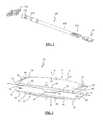
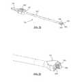
- FIG. 1is a perspective view of an example of a lateral total disc replacement (TDR) system and inserter according to a first embodiment of the present invention
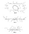
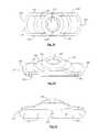
- FIG. 2is a perspective view of an assembled lateral TDR system according to a first embodiment of the present invention
- FIGS. 3-4are side (anterior or posterior) and end (lateral) views, respectively, of the lateral TDR system of FIG. 2 ;
- FIGS. 5-6are exploded top and bottom perspective views, respectively, of the lateral TDR system of FIG. 2 ;
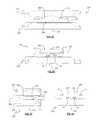
- FIGS. 7-8are exploded side (anterior or posterior) and end (lateral) views, respectively, of the lateral TDR system of FIG. 2 ;
- FIGS. 9-10are top and bottom perspective views, respectively, of a first anchor plate forming part of the lateral TDR system of FIG. 2 ;
- FIGS. 11-12are side (anterior or posterior) and end (lateral) views, respectively, of the first anchor plate forming part of the lateral TDR system of FIG. 2 ;
- FIGS. 13-14are top and bottom perspective views, respectively, of a second anchor plate forming part of the lateral TDR system of FIG. 2 ;
- FIGS. 15-16are side (anterior or posterior) and end (lateral) views, respectively, of the second anchor plate forming part of the lateral TDR system of FIG. 2 ;
- FIGS. 17-19are top perspective, side (lateral), and bottom perspective views, respectively, of an intradiscal element forming part of the lateral TDR system of FIG. 2 ;
- FIG. 20is a bottom perspective view of an alternative embodiment of the intradiscal element forming part of the lateral TDR system of FIG. 2 ;
- FIGS. 21-22are perspective and end views, respectively, of an example of a lateral TDR system according to a second embodiment of the present invention, wherein a second anchor plate has an angled cross-section to force the adjacent vertebral bodies into a predetermined position upon implantation (e.g. lordosis in lumbar spine and kyphosis in the thoracic spine);
- FIGS. 23-24are top perspective and end (lateral) views, respectively, of the second anchor plate forming part of the lateral TDR system of FIG. 21 ;
- FIGS. 25-26are perspective views of the entire inserter of FIG. 1 and the distal end of the inserter of FIG. 1 , respectively;
- FIG. 27is a top view of the distal end of the inserter of FIG. 1 ;
- FIG. 28is a perspective view of the distal engagement region of the insertion tool of FIG. 26 positioned to receive a lateral TDR system of FIG. 2 ;
- FIG. 29is a top view of the distal engagement region of FIG. 39 shown engaged with a lateral TDR system of FIG. 2 ;
- FIGS. 30-31are exploded and assembled perspective views, respectively, of the inserter of FIG. 1 (without a T-handle for clarity);
- FIGS. 32-34are exploded and assembled perspective views of a T-handle assembly forming part of the inserter of FIG. 1 ;
- FIG. 35is a perspective view of an exemplary pusher for use with the lateral TDR system and inserter according to one embodiment of the present invention.
- FIGS. 36-40are front (distal) perspective, rear (proximal) perspective, top, side (lateral), and rear (proximal) views, respectively, of an exemplary sizer for use with the lateral TDR system of FIG. 1 ;
- FIGS. 41-44are perspective views of the lateral TDR system and inserter of FIG. 1 , illustrating sequential steps in the use of the inserter and pusher to insert the lateral TDR system of FIG. 1 into an intervertebral space;
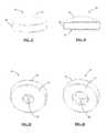
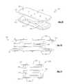
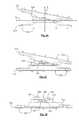
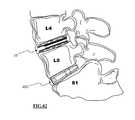
- FIGS. 45-47are top, anterior, and lateral views, respectively, of the lateral TDR system of FIG. 2 positioned within the intervertebral disc space according to one embodiment of the present invention
- FIGS. 48-49are exploded and assembled perspective views, respectively, of a lateral TDR system according to an alternative embodiment of the present invention.
- FIGS. 50-51are side (anterior or posterior) and end (lateral) views, respectively, of the lateral TDR system of FIG. 48 ;
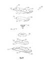
- FIGS. 52-53are assembled and exploded perspective views, respectively, of an intradiscal assembly forming part of the lateral TDR system of FIG. 48 ;
- FIGS. 54-55are assembled and exploded perspective views, respectively, of the lateral TDR system of FIG. 48 ;
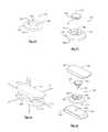
- FIG. 56is a perspective view of the underside of a first anchor plate forming part of the lateral TDR system of FIG. 48 ;
- FIG. 57is a perspective view of the underside of a first intradiscal insert forming part of the lateral TDR system of FIG. 48 ;
- FIG. 58is a perspective view of the intradiscal insert of FIG. 57 coupled with the anchor plate of FIG. 56 ;
- FIGS. 59-61are top, top perspective, and bottom perspective views, respectively, of the lateral TDR system of FIG. 48 with the first anchor plate and first intradiscal insert removed;
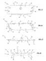
- FIGS. 62-63are side (anterior or posterior) views of an intradiscal element in conjunction with a first and second intradiscal insert according to one embodiment of the present invention, wherein the intradiscal element has been made transparent to show the relative positioning of the anchor pin;
- FIGS. 64-65are end (lateral) views of an intradiscal element in conjunction with a first and second intradiscal insert according to a first embodiment of the present invention, wherein the intradiscal element has been made transparent to show the relative positioning of the anchor pin;
- FIG. 66is a side (anterior or posterior) view of the lateral TDR system of FIG. 48 , illustrating rotation about the Z-axis;
- FIG. 67is a side (anterior or posterior) view of the lateral TDR system of FIG. 66 , wherein the intradiscal element has been made transparent to show the relative positioning of the anchor pin;
- FIG. 68is a side (anterior or posterior) view of the lateral TDR system of FIG. 67 with a first anchor plate and first intradiscal insert removed, wherein the intradiscal element has been made transparent to show the relative positioning of the anchor pin;
- FIG. 69is an end (lateral) view of the lateral TDR system of FIG. 48 , illustrating rotation about the X-axis;
- FIG. 70is an end (lateral) view of the lateral TDR system of FIG. 69 , wherein the intradiscal element has been made transparent to show the relative positioning of the anchor pin;
- FIG. 71is an end (lateral) view of the lateral TDR system of FIG. 70 with a first anchor plate and first intradiscal insert removed, wherein the intradiscal element has been made transparent to show the relative positioning of the anchor pin;
- FIG. 72is a perspective view of an example of an insertion tool according to an alternative embodiment of the present invention coupled to an example of a lateral TDR system according to one embodiment of the present invention
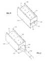
- FIG. 73is a perspective view of an insertion cradle forming part of the insertion tool of FIG. 72 ;
- FIG. 74is a front view of the insertion cradle of FIG. 73 ;
- FIG. 75is a front view of a lateral TDR system coupled to the insertion cradle of FIG. 73 ;
- FIG. 76is a perspective view of a lateral TDR system coupled to the insertion cradle of FIG. 73 ;
- FIG. 77is a perspective view of the distal region of the insertion tool coupled to the combined insertion cradle and lateral TDR system as shown in FIG. 72 ;
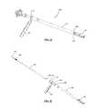
- FIG. 78is a perspective view of an elongated inserter forming part of the insertion tool of FIG. 72 ;
- FIG. 79is an enlarged perspective view of the distal end of the elongated inserter of FIG. 78 ;
- FIG. 80is an exploded view of the elongated inserter of FIG. 78 , illustrating the component parts of the elongated inserter according to one embodiment of the present invention
- FIGS. 81-82are anterior and lateral views, respectively, of the lateral TDR system of FIG. 2 in combined use with an anterior lumbar interbody fusion (ALIF) device according to one embodiment of the present invention.
- ALIFanterior lumbar interbody fusion
- FIGS. 83-84are anterior and lateral views, respectively, of the lateral TDR system of FIG. 2 in combined use with a trans-sacral interbody fusion device according to one embodiment of the present invention.
- FIG. 1illustrates an example of a lateral total disc replacement (TDR) system 10 according to a first embodiment of the present invention and an example of an insertion tool 100 (including a T-handle assembly 152 ) used to insert the lateral TDR system 10 into an intervertebral space of a spine.
- the lateral TDR system 10 disclosed herein(as well as alternative embodiments thereof) is dimensioned for lateral insertion into the intervertebral space using minimally invasive techniques, such shown and described in commonly owned and co-pending International Patent Application No. PCT/US2004/031768, entitled “Surgical Access System and Related Methods” (filed Sep. 27, 2004, claiming priority from U.S. Provisional Patent Application Ser. Nos. 60/506,136 filed Sep.
- the '768 PCTdescribes a neurophysiology-based surgical access system whereby an operative corridor may be established to a spinal target site in a generally lateral manner such that an implant may be introduced into the lateral aspect (side) of the surgical target site (e.g. disc space).
- the lateral approachis preferably retroperitoneal and trans-psoas, the latter of which is aided via the use of intra-operative neural monitoring (continuous and/or intermittent) to ensure nerves within or adjacent to the psoas muscle are not impinged upon and/or damaged during the step of establishing the operative corridor through the psoas muscle.
- the insertion tool 100is provided with a distal engagement region 102 adapted to securely engage the lateral TDR system 10 during insertion and to further allow for a simple, safe and effective disengagement once the lateral TDR system 10 is implanted.
- the lateral TDR system 10includes a first anchor plate 12 , a second anchor plate 14 , and an intradiscal element 16 .
- the lateral TDR system 10is adapted for minimally invasive lateral insertion into an intervertebral space.
- each anchor plate 12 , 14is generally rectangular in shape, having a length dimension (defined by a distance along an “X” axis) greater than a width dimension (defined by a distance along a “Z” axis).
- the lateral TDR system 10 of the present inventionmay be provided with varying length, width, and height dimensions depending on the position within the spine of the target intervertebral disc space, as well as individual patient anatomies.
- the lateral TDR system 10may be provided having dimensions falling within the ranges of 40-55 mm in length, 18-22 mm in width, and 8-14 mm in height.
- the lateral TDR implant sizeshould be selected such that at least one and preferably more than one anti-migration feature provided thereon rests on the hard cortical ring, thereby reducing the possibility of subsidence through the vertebral endplates.
- the lateral TDR system 10 of the present inventionmay be provided with first and second anchor plates 12 , 14 having a shape other than generally rectangular, including by way of example only generally circular, generally elliptical and/or generally curved. Such alternative shapes may be provided for other surgical techniques (e.g. open procedures) and/or approaches (e.g. anterior, posterior, antero-lateral and postero-lateral).
- the intradiscal element 16may be positioned in any number of suitable locations relative to the first anchor plate 12 and second anchor plate 14 , such as (by way of example only) off-center from an X-axis (as shown in FIG. 2 ) such that the intradiscal element 16 is disposed in the posterior region (e.g. in the posterior one-third) of the disc space when disposed in the lumbar spine. This ensures that the instantaneous axis of rotation of the lateral TDR system 10 will be disposed in the posterior region (e.g. in the posterior one-third) of the disc space, which is believed to be the proper intervertebral position for optimum motion preservation performance. This is evident with reference to FIGS. 4 & 47 .
- providing the intradiscal element 16 in this “automatically posterior” positionsis advantageous in that it allows for a simplified insertion process in that when a surgeon inserts the lateral TDR system 10 into the middle of the intradiscal space, the intradiscal element 16 will automatically be placed in the posterior region of the disc space.
- Thisincreases the efficiency of the procedure and ensures proper placement of the lateral TDR system 10 , which decreases the amount of time required for the operation.
- the first and second anchor plates 12 , 14can each be defined as having a posterior side 13 and an anterior side 15 .
- FIGS. 9-12detail the first anchor plate 12 , which includes a first surface 18 for engaging a first vertebra and a generally planar second surface 20 opposite said first surface 18 .
- a recess 22may be provided at the approximate midline or middle (relative to the X-axis) of the second surface 20 .
- the recess 22includes a semi-spherical articular surface 24 dimensioned to receive at least a portion of the intradiscal element 16 .
- the recess 22is positioned towards the posterior side 13 of the first anchor plate 12 in order to accommodate the posterior bias of the intradiscal element 16 .
- the recess 22interacts with the intradiscal element 16 to allow for translational and/or rotational movement of the first anchor plate 12 relative to the second anchor plate 14 .
- the second surface 20may include a raised perimeter 26 around the recess 22 to increase the surface area of the partially spherical articular surface without impacting the overall profile of the lateral TDR system 10 .
- FIGS. 13-16detail the second anchor plate 14 , which includes a first surface 30 for engaging a second vertebra and a generally planar second surface 32 opposite said first surface 30 .
- the second anchor plate 14further includes a post element 34 provided at the approximate midline (i.e. along the Z-axis) of the second surface 32 .
- the post element 34is provided in a posteriorly-biased offset orientation (e.g. toward posterior side 13 ) to accommodate the posterior bias of the intradiscal element 16 .
- the post element 34should have a placement on the second anchor plate 14 generally opposite the recess 22 located on the first anchor plate 12 .
- the post element 34may be generally cylindrical in shape and dimensioned to be received within a central bore 46 of the intradiscal element 16 (described in further detail below).
- a plurality of anti-migration features 36may be provided on the first and second anchor plates 12 , 14 to inhibit the movement of the plates after introduction into an intervertebral space.
- the anti-migration features 36may comprise protrusions having a generally triangular cross-section, although any number of suitable configurations or anti-migration elements may be employed without departing from the scope of the present invention.
- the anti-migration features 36may be provided in any number or arrangement, it is preferable to include at least three anti-migration features 36 arranged along a longitudinal midline (i.e. co-linear with the X-axis) and at least three anti-migration features 36 arranged along a lateral midline (i.e.
- the longitudinally aligned anti-migration featuresmay be used as a guide while inserting the lateral TDR system 10 from a lateral direction to ensure proper placement relative to the anterior and posterior portions of the spine.
- the laterally aligned anti-migration featuresmay be used as a guide to confirm proper placement by ensuring these anti-migration features are in line with the middle of the vertebral bodies (from an anterior view) and/or spinous process. This ensures that the lateral TDR system 10 is in proper positioning relative to the lateral sides of the spine.
- any number of mechanisms or techniquesmay be employed to introduce the first and second anchor plates 12 , 14 into an intervertebral space, including but not limited to providing a first pair of grooves 38 located on either side and traversing the length of the first anchor plate 12 and a second pair of groves 40 located on either side and traversing the length of the second anchor plate 14 .
- at least one recess 42is provided within each groove 38 near an end of the first anchor plate 12 .
- a pair of recesses 42are provided within each groove 38 , with one recess 42 located near each end of the first anchor plate 12 .
- at least one recess 44is provided within each groove 40 near an end of the second anchor plate 14 .
- a pair of recesses 44are provided within each groove 40 , with one recess 44 located near each end of the second anchor plate 14 .
- Recesses 42 , 44are dimensioned to interact with the lateral TDR insertion tool 100 to provide a “snap-fit” engagement between the lateral TDR system 10 and the insertion tool 100 , described in further detail below.
- a plurality of apertures 46 extending through the first anchor plate 12 from the first surface 18 to the second surface 20may be provided for facilitating engagement between an insertion or removal tool (not shown) and the first anchor plate 12 .
- a plurality of apertures 48 extending through the second anchor plate 14 from the first surface 30 to the second surface 32may be provided for facilitating engagement between an insertion instrument or removal tool (not shown) and the second anchor plate 14 .
- the first and second anchor plates 12 , 14may be constructed from any number of materials and/or compositions suitable for medical applications, including but not limited to metallic compositions (such as titanium) or alloys (such as Co—Cr—Mo), ceramics (such as zirconia and/or alumina), polymers (such as ultra-high molecular weight polyethylene), and/or any combination thereof. Where beneficial and appropriate, either or both of the first and second anchor plates 12 , 14 may also be coated with any number of suitable compositions, such as zirconium oxide coating found in U.S. Pat. No. 5,037,438, the contents of which are hereby incorporated into this disclosure as if set forth in its entirety.
- FIGS. 17-20detail the intradiscal element 16 , which may be provided as a single piece having a generally cylindrical base 50 , a first articular surface 52 and a second generally planar surface 54 opposite said first articular surface 52 . Although shown and described as generally cylindrical in shape, the intradiscal element 16 may comprise any shape that allows for a complete range of motion, including but not limited to circular, oval, square, and rectangular.
- the first articular surface 52is dimensioned to articulate with semi-spherical articular surface 21 of the recess 22 of the first anchor plate 12 such that the first anchor plate 12 may freely rotate relative to the intradiscal element 16 about any axis defined by a line within the XZ plane that intersects the Y-axis (or an axis parallel thereto when the post element 34 is posteriorly biased).
- the second generally planar surface 54is dimensioned to interact with the second generally planar surface 32 of the second anchor plate 14 such that the second anchor plate 14 may freely rotate relative to the intradiscal element 16 about the Y-axis. In this fashion, rotation about any axis in the XZ plane will always occur at the same location along the first anchor plate 12 and rotation about the Y-axis will always occur at the same location along the second anchor plate 14 .
- the second generally planar surface 54includes a central bore 56 dimensioned to receive the post element 34 of the second anchor plate 14 .
- Central bore 56may be generally circular in shape, and have any diameter necessary to allow for an optimal range of translation of the intradiscal element 16 , which may vary between different embodiments of the total disc replacement system 10 and depend on the desired destination of the implant (e.g. lumbar, thoracic, and cervical spine).
- the intradiscal element 16 shown in FIG. 19includes a central bore 56 having a diameter only marginally greater than the diameter of the post element 34 so as to allow coupling of the post element 34 with the bore 56 .
- the intradiscal element 16 as shown in FIG. 20includes a central bore 56 having a diameter that is greater than the outer diameter of the post element 34 . This allows for translation of the intradiscal element 16 in any direction in the XZ plane as well as for axial rotation about the Y-axis (or an axis parallel thereto).
- the intradiscal element 16may be pre-attached, molded, or otherwise integrated in a fixed relationship to the second anchor plate 14 .
- the lateral TDR system 10has been described as allowing for free rotation/translation of the first and second anchor plates 12 , 14 the extent of such rotation/translation will be constrained only by the natural limitations of the human body (muscles, ligaments, spinal structure, etc).
- the lateral TDR system 10 of the present inventionallows the spine to retain its full range of motion with respect to flexion, extension, and lateral bending.
- rotation about the Y-axis as described aboveallows for full retention of the spine's axial rotation abilities.
- the lateral TDR system 10 of the present inventionprovides for complete motion retention capabilities of a normal human spine.
- the second anchor plate 14When used within the lumbar spine, for example, it may be desirable to configure the second anchor plate 14 such that the post element 34 is located within the posterior one-third of the disc space (and generally within the frontal plane of the patient) to approximate the axis of rotation of the natural spine during flexion and extension. It may similarly be desirable to configure the first anchor plate 12 such that the recess 22 is located at the approximate center of the disc space (and generally within the sagittal plane of the patient) to approximate the axis of rotation of the natural spine during lateral bending. Although described by way of example in this configuration, it will be appreciated that the relative position of the recess 22 and post element 34 may be altered in any number of different fashions depending upon the vertebral level (i.e.
- the lateral TDR system 10may be introduced into a disc space in the orientation shown (with the first anchor plate 12 “above” the second anchor plate 14 such that the anti-migration features 36 are to be disposed within a respective “upper” and “lower” vertebral level within the patient) or vice versa.
- the intradiscal element 16may be constructed from any number of materials and/or compositions suitable for medical applications, including but not limited to metallic compositions or alloys (such as Co—Cr—Mo), ceramics (such as zirconia and/or alumina), polymers (such as ultra-high molecular weight polyethylene), and/or any combination thereof. Where beneficial and appropriate, the intradiscal element 16 may also be coated with any number of suitable compositions, such as the zirconium oxide coating mentioned above.
- FIGS. 21-24illustrate an alternate embodiment of the lateral TDR system 10 of the present invention, adapted (by way of example only) for placement within a lordotic region of the spine (e.g. lumbar region).
- a lordotic region of the spinee.g. lumbar region.
- the second anchor plate 14with an asymmetrical or angled cross-sectional thickness in the anterior-posterior (A-P) plane (i.e. along the Z-axis). More specifically, the second anchor plate 14 has an anterior side 15 that is thicker than the posterior side 13 . This configuration allows the lateral TDR system 10 to effectively engage the vertebrae by accounting for the natural curvature of the lumbar spine.
- anchor plates 12 , 14may be similarly dimensioned to force the adjacent vertebral bodies of the thoracic spine into kyphosis and that this is contemplated as part of the present invention.
- the lateral TDR system 10may be provided in one or more surgical kits offering implants of varying dimensions.
- the size (e.g. length, width, and height) of the implantmay be determined during the surgical procedure (for example, by using the trail sizers 190 described below) when it may best be assessed.
- Table 1 belowset forth by way of example only, illustrates the dimensions of endplates 12 , 14 , both regular and lordotic, available in one exemplary kit. Although set forth below having a lordotic angle of 5 degrees, it will be appreciated that the angle of lordosis may be provided in any number of suitable angles without departing from the scope of the present invention, including but not limited to 1 degree to 15 degrees.
- FIGS. 25-31illustrate an example of an insertion tool 100 for inserting a lateral TDR system 10 into a prepared intervertebral space according to one embodiment of the present invention.
- the insertion tool 100is configured to releasably maintain the lateral TDR system 10 in the proper orientation during lateral insertion into an intervertebral disc space and thereafter release the lateral TDR system 10 upon successful placement.
- the lateral TDR system 10having been deposited in the intervertebral space, facilitates normal spinal functionality over time by maintaining a restored disc height (due to the structural and load-bearing capabilities of the lateral TDR system 10 ) as well as retaining a normal range of motion.
- the insertion tool 100 of the present inventionis not limited to interaction with the lateral TDR systems disclosed herein, but rather may be dimensioned to engage any laterally-inserted TDR system.
- the insertion tool 100 of the present inventionincludes a distal engagement region 102 , an elongated shaft 104 , a tubular lock member 106 , a proximal attachment member 132 and a removable T-handle assembly 152 provided in accordance with a first embodiment of the present invention.
- the insertion tool 100is similar to the inserter shown and described in commonly owned U.S. Pat. No.
- the insertion toolmay include a cradle member threadedly engaged with an elongated inserter, as described below.
- FIGS. 26-29detail the distal engagement region 102 , which is positioned at the distal end of elongated shaft 104 and consists of a pair of clamping arms 107 , 109 , each including a generally “L”-shaped prong 108 , 110 , respectively.
- the prongs 108 , 110are coupled with the clamping arms 107 , 109 so that the prongs 108 , 110 are restrained from movement relative to the clamping arms 107 , 109 .
- the clamping arms 107 , 109are generally parallel and spaced apart from one another when in a freestanding configuration.
- the prongs 108 , 110are oriented such that each respective “L” shape faces one another, thereby forming a cradle 112 for engagement with the lateral TDR system 10 .
- each clamping arm 107 , 109includes a tapered surface 111 , 113 , respectively, in which the larger dimension is oriented closest to the cradle 112 and the smaller dimension is oriented closest to the elongated shaft 104 .
- the clamping arms 107 , 109become generally semi-cylindrical such that when viewed together the clamping arms 107 , 109 have a generally cylindrical shape and a constant diameter approximately matching the smallest outer dimension of the taper features 111 , 113 . This constant diameter is maintained by the elongated shaft 104 proximal to the clamping arms 107 , 109 .
- the cradle 112is generally rectangular in shape, but may take the form of any geometric shape necessary to interact with the lateral TDR system 10 , including but not limited to generally oval, square, and triangular.
- the distal engagement region 102may be composed of any material suitable for facilitating the insertion of a TDR system 10 into an intervertebral space, including but not limited to metal (e.g. titanium), ceramic, and/or polymer compositions.
- the cradle 112engages the lateral TDR system 10 with a “snap-fit” engagement described below.
- the cradle 112may engage the lateral TDR system 10 by any suitable means of engagement, including but not limited to a threaded engagement, hooks, and/or compressive force.
- Prongs 108 , 110each have an inside surface 114 , 118 and an outside surface 116 , 120 , respectively.
- inside surfaces 114 , 118may be generally planar, but may have any configuration suitable for interaction with TDR system 10 , including but not limited to generally planar, generally concave, and generally convex.
- Outside surfaces 116 , 120may have any configuration suitable for facilitating insertion of a TDR system 10 into a prepared intervertebral disc space, including but not limited to generally planar, generally concave, and generally convex (as shown in the figures by way of example only).
- Prongs 108 , 110each have a first engagement ridge 122 and a second engagement ridge 124 extending at least partially along the length of inside surfaces 114 , 118 .
- First engagement ridges 122are dimensioned to be received within first grooves 38 on either side (posterior and anterior) of the first anchor plate 12 (shown and described above).
- Second engagement ridges 124are dimensioned to be received within second grooves 40 on either side of second anchor plate 14 .
- first engagement ridges 122may each further include one or more protrusions 126 situated near the proximal end of the ridge 122 .
- Protrusions 126are dimensioned to be received within recesses 42 on either side of first anchor plate 12 .
- second engagement ridges 124may each further include one or more protrusions 128 situated near the proximal end of the ridge 124 and dimensioned to be received within recesses 44 on either side of second anchor plate 14 .
- Engagement of the lateral TDR system 10 to the inserter 100make possible the simultaneous insertion of TDR system 10 .
- the entire system 10may be inserted into the targeted disc space in one insertion step as opposed to multiple insertion steps required to, essentially, build a construct within the disc space, as is required by some total disc replacement implants known in the art.
- FIGS. 30-31detail the elongated shaft 104 , the tubular lock member 106 , and the proximal attachment member 132 (with the T-handle assembly 152 removed).
- the elongated shaft 104extends proximally from the distal engagement region 102 to a proximal end 130 to which the proximal attachment member 132 may be attached.
- the elongated shaft 104is generally cylindrical and of a length sufficient to allow the device to span from the surgical target site to a location sufficiently outside the patient's body so to enable insertion of the lateral TDR system 10 .
- Elongated shaft 104may further included a threaded region 134 located near the proximal end 130 .
- Threaded region 134may be dimensioned to threadedly engage the proximal engagement region 148 of the tubular lock member 106 , as described further below.
- the elongated shaft 104may be provided with an interior lumen 136 extending therethrough.
- the proximal attachment member 132is generally cylindrical in shape and is dimensioned to be attached to the proximal end 130 of the elongated shaft 104 .
- the proximal attachment member 132may be provided with a generally hexagonal-shaped tool engagement region 138 at its distal end and a T-handle engagement region 140 at its proximal end. In the example shown in FIG.
- the T-handle engagement region 140is provided as a pair of recesses 142 dimensioned to receive attachment flanges 164 of the T-handle assembly 152 , thus facilitating the attachment of the T-handle assembly 152 to the elongated rod 104 .
- the T-handle engagement regionmay have any shape or configuration complementary to the shape and configuration of the attachment flanges 164 .
- the proximal attachment member 132is further provided with a lumen 144 extending therethrough dimensioned to receive (at least at a distal end) the proximal end 130 of the elongated shaft 104 .
- Lumens 136 , 144are dimensioned to be contiguous such that an instrument such as a push rod 180 may traverse the length of the elongated shaft and engage the lateral TDR system 10 .
- the proximal attachment member 132may be permanently mated to the elongated shaft 104 or may be removable.
- Lumen 144may further include a threaded region (not shown) at its distal end to interact with the T-handle assembly 152 as described below.
- the tubular lock member 106is an elongated member having a lumen 146 extending therethrough.
- Lumen 146is dimensioned to receive the elongated shaft 104 .
- the lumen 146includes a diameter slightly larger than that of the elongated shaft 104 .
- the tubular lock memberfurther includes a proximal engagement region 148 having a tool engagement region 150 .
- the interior of the lumen 146may be provided with a threaded region (not shown) near the proximal end 148 dimensioned to threadedly engage the threaded region 134 of the elongated shaft 104 . This threaded mating enables controlled migration of the tubular lock member 106 along the elongated shaft 104 .
- the diameter of the tubular lock member 106is greater than that of the elongated shaft 104 , but less than the widest part of tapered surfaces 111 , 113 . As will be explained in greater detail below, this enables the tubular lock member to force the prongs 108 , 110 together, giving further stability to the cradle 112 as it engages the lateral TDR system 10 .
- the insertion tool 100is provided to a user (e.g.
- the elongated shaft 104fully assembled—that is with the elongated shaft 104 inserted through and threadedly engaging the tubular lock member 106 and the proximal attachment member 132 attached to the elongated shaft 104 , though it is contemplated that one or more parts of the insertion tool 100 may be provided separately from the others.
- FIGS. 32-34detail the T-handle assembly 152 , which includes a handle 154 and a pin 156 .
- the handle 154includes a pair of lateral extensions 158 each having a contoured surface 160 dimensioned to comfortably interact with a user's hand.
- the handle 154further includes an aperture 162 extending through the width of the handle 154 at an approximate midline and a pair of attachment flanges 164 dimensioned to engage with recesses 142 of the T-handle engagement region 140 of the proximal attachment member 132 .
- the interior of aperture 162may include a threaded region 166 .
- the handle 154may be further provided with a button 168 at the end of one of the lateral extensions 158 to provide an indication of the orientation of the lateral TDR system 10 , when the lateral TDR system 10 includes an offset post 34 as described above.
- the button 168may be preferably used to denote the posterior side 13 of the lateral TDR system 10 so that a user will be certain of the correct orientation of the lateral TDR system 10 prior to and during insertion into a patient. The button 168 thus minimizes the occurrence of improper insertion thereby leading to a more efficient surgical procedure. Additional safety measures are also contemplated to ensure the proper orientation of the lateral TDR system 10 on insertion.
- the handle 154may be inscribed with one or more marking to visually indicate the proper orientation. As illustrated in FIGS. 33-34 , the words “POSTERIOR” and “ANTERIOR” are prominently displayed on handle. Preferably this safety feature may be used in addition to button 168 .
- insertion tool 100 and/or TDR system 10may be modified in such a way that engagement of TDR system 10 to distal engagement region 102 may only occur in the proper orientation. This may be accomplished for example, by providing different size recesses 42 , 44 , on the posterior 13 and anterior 15 sides of anchor plates 12 , 14 . In another embodiment this may be accomplished by altering the shape of ridges 38 , 40 on only one side (e.g. posterior side 13 ) of anchor plates 12 , 14 .
- a pin 156is provided to securely mate the T-handle to the proximal attachment member 132 of the elongated shaft 104 .
- the pin 156includes a head region 170 and a shaft 172 .
- the head region 170is generally cylindrical in shape and includes a contoured surface 174 to improve the grip for a user.
- the shaft 172is dimensioned to traverse the aperture 162 and includes a set of threads 176 dimensioned to threadedly engage threaded region 166 of aperture 162 and also the lumen 144 of the proximal attachment member 132 .
- the handle 154may further include a recess 178 dimensioned to receive at least a portion of the head region 170 so as to reduce the overall profile of the T-handle assembly 152 .
- FIG. 35illustrates an example of a push rod 180 for use with the insertion tool 100 described above.
- the push rod 180is an elongated member having a proximal end 182 , a distal end 184 and an elongated shaft 186 extending therebetween.
- the proximal endis dimensioned to attach to a detachable handle member (not shown) to allow a user to manipulate the push rod 180 .
- the distal end 182may be generally flat and is dimensioned to engage with the lateral TDR system 10 of the present invention.
- the elongated shaft 186is generally cylindrical in shape and dimensioned to be slideably received within lumen 136 of the elongated shaft 104 .
- a threaded region 188may be provided at a proximal end of the elongated shaft 186 in order to threadedly engage the lumen 144 of the proximal attachment member 132 to allow for controlled release of the lateral TDR system 10 into an intervertebral space.
- FIGS. 36-40illustrate an example of a trial sizer 190 according to one embodiment of the present invention.
- Sizer 190may be provided in a variety of sizes (preferably corresponding to the available TDR system 10 sizes, such as for example, those sizes listed above in Table 1) to enable a clinician to determine the appropriate size of a TDR system 10 to insert into a particular patient's intervertebral space.
- the sizeris thus generally rectangular in shape, and has a distal end 192 , a proximal tool engagement feature 193 , first and second opposing sides 194 , 196 and at least one aperture 198 extending therethrough.
- the distal end 192may be slightly tapered in shape to allow for self-distraction of the disc space during insertion of the initial sizer 190 .
- the proximal tool engagement feature 193may be provided in any suitable fashion to allow interaction with any desirable insertion tool.
- the first and second opposing surfaces 194 , 196are each provided having a generally convex proximal-to-distal profile and a generally convex lateral profile to enable the sizer 190 to anticipate the shape of the intervertebral space.
- Apertures 198may be provided in any shape and size and function to reduce the overall mass of the sizer 190 .
- a cliniciancan utilize the lateral TDR system 10 in either an open or minimally invasive lateral total disc replacement procedure.
- a working channelwould be created in a patient that reaches the targeted spinal level.
- the intervertebral spacemust be prepared, meaning the disc space must be accessed via an annulotomy followed by a full or partial discectomy.
- End plate preparationmay or may not be performed according surgeon preference, among other factors.
- the final step of disc space preparationentails releasing the contra-lateral annulus (i.e. the annulus directly across the disc space from the original entry point into the disc).
- Releasing the contra-lateral annulusis advantageous in that it increases the likelihood of proper motion preservation after the lateral TDR system 10 is implanted due to the elimination of a potentially limiting tension band in the form of the contra-lateral annulus.
- the clinicianhas prepared the disc space and determined the correct size of TDR system 10 to use (by using the sizer 190 )
- the lateral TDR system 10is ready to be attached to the inserter 100 and inserted into the disc space. As shown by example in FIGS.
- the clinicianwill engage the cradle 112 to the lateral TDR system 10 by sliding ridges 122 , 124 into grooves 38 , 40 , respectively, until protrusions 126 , 128 engage recesses 42 , 44 and the lateral TDR system 10 is secured onto the insertion tool 100 .
- the insertion tool 100is used to place the lateral TDR system 10 into the prepared intervertebral space. Once the lateral TDR system 10 is inserted into the prepared space into the desired position (shown in FIGS. 45-47 , which may be confirmed via fluoroscopy or any other suitable imaging technique), the lateral TDR system 10 is released from the inserter 100 .
- FIGS. 41-44illustrate an example of an insertion procedure of the lateral TDR system 10 using the insertion tool 100 .
- the tubular lock member 106may then be used to lock the lateral TDR system 10 within the cradle 112 . This is accomplished by advancing the tubular lock member 106 along the elongated shaft 104 such that the distal end of the tubular lock member 106 approaches the tapered surfaces 111 , 113 (see e.g. FIGS. 26-27 ), forcing the prongs 108 , 110 together and creating a compressive force on the lateral TDR system 10 .
- a toolsuch as a wrench 197 may be applied to the tool engagement region 150 and turned such that the threaded region of lumen 146 and threaded region 134 of the elongated shaft 104 interact to controllably advance the tubular lock member 106 .
- anti-migration features 36may be utilized as guides. As previously mentioned, anti-migration features 36 may preferably be arranged along the longitudinal midline (i.e. co-linear with the X-axis) and the lateral midline (i.e. co-linear with the Z-axis) of anchor plates 12 , 14 . Prior to inserting the system 10 a surgeon may first determine the longitudinal midline of the intervertebral space (i.e.
- an indicatorsuch as, by way of example, a radiographic marker in the form of a screw 17
- Thismay be particularly important (for example) if a posteriorly-biased configuration is used.
- Fluoroscopic imagingmay be used to check the alignment of anti-migration features 36 with screw 17 .
- the lateral TDR system 10may then be inserted such that the anti-migration features 36 aligned on the longitudinal midline of plates 12 , 14 line up with the indicator on the longitudinal midline of the intervertebral space, thus ensuring proper positioning in the anterior-posterior direction.
- the anti-migration features 36 aligned along the lateral midline of anchor plates 12 , 14may be placed inline with the spinous processes and/or the lateral midline (from anterior view) of one or more of the adjacent vertebral bodies. Either or both of these alignment techniques helps ensure the proper lateral alignment of the lateral TDR system 10 according to one aspect of the present invention.
- FIG. 45illustrates, by way of example only, the proper positioning of the lateral TDR system 10 within the disc space from a top-down view.
- Anti-migration features 36 aligned along the longitudinal and lateral midlines of anchor plates 12 , 14are positioned inline with the midline indicator and spinous process, respectively.
- FIG. 46is an anterior view of TDR system 10 properly positioned in the disc space.
- the central row of anti-migration features 36 arranged along the lateral midline of anchor plates 12 , 14line up with the lateral midline of the vertebra.
- FIG. 47is an anterior view of the lateral TDR system 10 properly positioned in the disc space.
- the central row of anti-migration features 36are aligned with the longitudinal midline of the vertebra. As viewed in FIG.
- the center of intradiscal element 16is automatically disposed in the posterior region of the disc space and separated from the longitudinal midline of the vertebra by a distance d 1 .
- the distance d 1is preferably such that the center of intradiscal element 16 is positioned within the posterior region of the disc space (most preferably within the posterior one-third of the disc space).
- Proper positioning of the system 10 within the disc spaceincludes not only the alignment of the lateral TDR system 10 , but also preferably includes having the lateral ends of the anchor plates 12 , 14 disposed over the hard cortical ring of the adjacent vertebral bodies.
- the rows of anti-migration features 36 disposed on the lateral ends of the anchor plates 12 , 14are preferably positioned on the hard cortical ring of the adjacent vertebral bodies, which advantageously aids in preventing the unwanted migration of the anchor plates 12 , 14 from the optimal location after implantation.
- the wrench 197is removed from the tool engagement region 150 of the tubular lock member 106 and mated with the tool engagement region 138 of the proximal attachment member 132 of the elongated shaft 104 .
- Thiswill enable the clinician to hold the elongated shaft 104 in place to prevent rotation during insertion and use of additional hardware such as push rod 180 .
- Push rod 180may then be inserted into lumen 144 of the proximal attachment member 132 and advanced along lumen 136 of the elongated shaft 104 until the distal end 184 encounters the lateral TDR system 10 (shown by way of example in FIG. 43 ).
- a handle member 199may be attached to the proximal end 182 to allow a user to apply sufficient force to the push rod 180 to force the lateral TDR system 10 out of the cradle 112 (shown by way of example in FIG. 44 ). Before forcing the lateral TDR system from the cradle 112 , however, it may be advantageous to unlock the tubular lock member 106 by applying wrench 197 to the tool engagement region 150 and turning in an opposite direction from the locking motion.
- the intradiscal element 16may be prevented from translating relative to the first and/or second anchor plates 12 , 14 in any suitable fashion, such as by equipping the either or both of the anchor plates 12 , 14 and/or the intradiscal element 16 with a structure (e.g. a wall member extending from the anchor plate) or by altering the difference in diameters between the post 34 and central bore 56 .
- a structuree.g. a wall member extending from the anchor plate
- an insertion toolmay be provided wherein the prongs are provided with a greater height than the lateral TDR system so as to allow the act of insertion of the lateral TDR system into the disc space simultaneously cause the distraction of the space.
- FIGS. 48-71illustrate a TDR system 210 according to an alternative embodiment of the present invention.
- the lateral TDR system 210includes a first anchor plate 212 , a second anchor plate 214 , a first and second intradiscal insert 216 , 218 , and an intradiscal element 220 .
- Each anchor plate 212 , 214is equipped with a plurality of anti-migration features 222 and a cutout region 224 , 226 , respectively.
- the first intradiscal insert 216has a first generally planar surface 228 dimensioned to fit into the cutout region 224 of the first anchor plate 212 ( FIGS.
- the second intradiscal insert 218has a first surface 234 dimensioned to fit into the cutout region 226 of the second anchor plate 214 and a second generally planar surface 236 dimensioned to interact with the intradiscal element 220 .
- FIGS. 52-53illustrate an exemplary embodiment of an intradiscal element 220 according to a first embodiment of the present invention.
- the intradiscal element 220may include a pivot 238 and retaining pin 240 .
- the pivot 238may comprise any shape that allows for a complete range of motion, including but not limited to circular, oval, square, and rectangular.
- the pivot 238is generally circular in shape, and includes a first articular surface 242 , a second generally planar surface 244 , and a cutout region 246 .
- the first articular surface 242is dimensioned to articulate with the second articular surface 230 of the first intradiscal insert 216 such that, by extension, the first anchor plate 212 may rotate relative to the intradiscal element 220 about any axis defined by a line within the XZ plane that intersects the Y-axis ( FIG. 54 ).
- the second generally planar surface 244is dimensioned to interact with the second generally planar surface 236 of the second intradiscal insert 218 such that, by extension, the second anchor plate 214 may rotate relative to the intradiscal element 220 about the Y-axis.
- Cutout region 246includes a central aperture 248 dimensioned to allow pin 240 to pass though pivot 238 and interact with second intradiscal insert 218 .
- Central aperture 248may be generally circular in shape, and have any diameter necessary to allow for an optimal range of motion, which may vary between different embodiments of the total disc replacement system 210 and depend on the desired destination of the implant (e.g. lumbar, thoracic, and cervical spine).
- the pin 240includes a shaped head region 250 and an elongated member 251 .
- Head region 250may comprise any shape allowing a complete range of motion, including but not limited to circular, oval, square, and rectangular. In a preferred embodiment, the head region 250 is generally circular to allow for smooth rotation in any direction. Head region 250 is dimensioned to interact with the cutout region 246 of the pivot 238 , such that the head region 250 prevents the pivot 238 from exceeding a desired range of motion once the pin 240 has been secured to the second intradiscal insert 218 and/or second anchor plate 214 . Thus, the head region 250 may be of any diameter necessary to accomplish this, provided that diameter is less than the diameter of the cutout region 246 and greater than the diameter of aperture 248 .
- Elongated member 251extends in a generally perpendicular manner from head region 250 and is dimensioned to couple with aperture 262 on second intradiscal insert 218 ( FIG. 55 ).
- the diameter of central aperture 248may be substantially greater than the diameter of elongated member 251 , and slightly greater than the difference in diameter between the head region 250 and cutout region 246 . These differences in diameters function to allow for translation of the first anchor plate along any axis in the XZ plane, with the actual distance providing a limit on the degree of translation allowed. Specifically, the first anchor plate 212 can only translate as far as the distance defined by the difference in radii between the head region 250 and cutout region 246 (denoted by lines d 1 in FIGS. 63 & 65 ). The difference in radii between the elongated member 251 and the central aperture 248 (denoted by lines d 2 is FIGS.
- pin 240may be manufactured such that the difference in radii between the head region 250 and the elongated member 251 is greater than 2d 2 , such that upon translation, a portion of head region 250 always overlaps at least a portion of pivot 238 ( FIGS. 68 & 71 ).
- the lateral TDR system 210 of this first embodimentprovides rotation along a plurality of axes (any axis in the XZ plane, and the Y-axis) and translation along a plurality of axes (any axis in the XZ plane). At least a portion of the distal region of elongated member 251 may be threaded to engage with second anchor plate 214 to provide for increased stability to the lateral TDR system 210 of the present invention.
- the second anchor plate 214When used within the lumbar spine, for example, it may be desirable to configure the second anchor plate 214 such that the cutout region 226 is located within the posterior one-third of the disc space (and generally within the frontal plane of the patient) to approximate the axis of rotation of the natural spine during flexion and extension. It may similarly be desirable to configure the first anchor plate 212 such that the cutout region 224 is located at the approximate center of the disc space (and generally within the sagittal plane of the patient) to approximate the axis of rotation of the natural spine during lateral bending. Although described by way of example in this configuration, it will be appreciated that the relative position of the cutout regions 224 , 226 may be altered in any number of different fashions depending upon the vertebral level (i.e.
- the lateral TDR system 210may be introduced into a disc space in the orientation shown (with the first anchor plate 212 “above” the second anchor plate 214 such that the anti-migration features 222 are to be disposed within a respective “upper” and “lower” vertebral level within the patient) or vice versa.
- the first anchor plate 212includes a generally planar surface 252 for engaging a vertebra and a plurality of generally angled surfaces 254 , which may extend in a ramp-like fashion away from the lateral edges of the first anchor plate 212 at least partially towards the cutout region 224 .
- the generally angled surfaces 254serve to limit the relative rotation of the lateral TDR system 210 about an axis in the XZ plane. That is, the first anchor plate 212 will be able to rotate about the desired axis until a generally angled surface 254 comes into contact with another structure, such as the second intradiscal insert 218 or the second anchor plate 214 .
- a cutout region 224may be provided at the approximate mid-line or middle of the first anchor plate 212 and is dimensioned to receive a first intradiscal insert 216 .
- the cutout region 224functions to prevent any lateral or rotational movement of the first intradiscal insert 16 in relation to first anchor plate 212 , as well as to reduce the overall profile of the lateral TDR system 210 of the present invention.
- the first intradiscal insert 216may serve as a protective intermediary between the intradiscal element 220 and first anchor plate 212 .
- a plurality of anti-migration features 222may be provided on the first anchor plates 212 to inhibit the movement of said anchor plate after introduction into a receiving area within a vertebra.
- the anti-migration features 222may comprise protrusions having a generally triangular cross-section, although any number of suitable configurations or anti-migration elements may be employed without departing from the scope of the present invention. Any number of mechanisms or techniques may be employed to introduce first anchor plate 212 into a vertebra, including but not limited to providing one or more lumens and/or grooves (not shown) in the first anchor plate 212 for coupling to or engaging with an insertion tool (not shown).
- Second anchor plate 214includes a generally planar surface 256 ( FIGS. 59-61 ) for engaging a vertebra, a plurality of generally angled surfaces 258 , and a cutout region 226 ( FIG. 48 ).
- Cutout region 226may be provided at the approximate mid-line or middle of the second anchor plate 214 and is dimensioned to receive a second intradiscal insert 218 .
- the cutout region 226functions to prevent any lateral or rotational movement of the second intradiscal insert 218 in relation to second anchor plate 214 , as well as reduce the overall profile of the lateral TDR system 210 of the present invention.
- the second intradiscal insert 218may serve as a protective intermediary between intradiscal element 220 and second anchor plate 214 .
- Second anchor plate 214may also include a central aperture 260 located approximately in the center of generally planar surface 256 .
- Central aperture 260may be generally circular in shape, and is dimensioned to receive the elongated member 251 of retaining pin 240 .
- Central aperture 260should therefore be aligned with aperture 262 of the second intradiscal insert 218 to allow each aperture 260 , 262 to receive the elongated member 251 of retaining pin 240 .
- Central aperture 260may be threaded to engage with a threaded embodiment of elongated member 251 discussed above.
- the second anchor plate 214may be equipped with the same anti-migration features 222 discussed above with reference to first anchor plate 212 such that a repeat discussion is not necessary. Similarly, any number of mechanisms or techniques may be employed to introduce the second anchor plate 214 into a vertebra, including but not limited to providing one or more lumens and/or grooves (not shown) in the second anchor plate 214 or coupling to or engaging with an insertion tool (not shown).
- the first and second anchor plates 212 , 214may be constructed from any number of materials and/or compositions suitable for medical applications, including but not limited to metallic compositions (such as titanium) or alloys (such as Co—Cr—Mo), ceramics (such as zirconia and/or alumina), polymers (such as ultra-high molecular weight polyethylene), and/or any combination thereof. Where beneficial and appropriate, either or both of the first and second anchor plates 212 , 214 may also be coated with any number of suitable compositions, such as zirconium oxide coating found in U.S. Pat. No. 5,037,438, the contents of which are hereby incorporated into this disclosure as if set forth in its entirety.
- the intradiscal element 220 of the present inventionmay be constructed from any number of materials and/or compositions suitable for medical applications, including but not limited to metallic compositions or alloys (such as Co—Cr—Mo), ceramics (such as zirconia and/or alumina), polymers (such as ultra-high molecular weight polyethylene), and/or any combination thereof.
- the intradiscal element 220may also be coated with any number of suitable compositions, such as zirconium oxide coating found in U.S. Pat. No. 5,037,438, the contents of which are hereby incorporated into this disclosure as if set forth in its entirety.
- pivot 238is constructed from ceramic
- retaining pin 240is constructed from a metallic composition, such as titanium.
- FIGS. 54-55illustrate a preferred configuration of the first and second intradiscal inserts 216 , 218 .
- the first intradiscal insert 216has a first generally planar surface 228 , a second articular surface 230 , and a measurable thickness therebetween.
- the first surface 228is dimensioned to fit into the cutout region 224 of the first anchor plate 212 . Accordingly, the length of the first intradiscal insert 216 traverses a substantial portion of the length of the first anchor plate 212 .
- the second articular surface 230is dimensioned to interact with the first articular surface 242 of the pivot 238 , allowing for the rotational movement of TDR system 210 discussed above.
- the first intradiscal insert 216may also form a protective barrier between the intradiscal element 220 and the first anchor plate 212 . This barrier serves to reduce friction between the first anchor plate 212 and intradiscal element 220 , ultimately enhancing the durability of the lateral TDR system 210 .
- the second intradiscal insert 218has a first surface 234 , a second generally planar surface 236 , and a measurable thickness therebetween.
- the first surface 234is dimensioned to fit into the cutout region 226 of the second anchor plate 214 . Accordingly, the length of the second intradiscal insert 218 traverses a substantial portion of the length of the second anchor plate 214 .
- the second generally planar surface 236is dimensioned to interact with the second generally planar surface 244 of the pivot 238 . As such, the second generally planar surface 236 functions to allow rotation of the first anchor plate about the Y-axis, as described above.
- the second intradiscal insert 218may also include an aperture 262 located approximately in the center of first surface 234 , and spanning the measurable thickness between first surface 234 and second generally planar surface 236 , said aperture 262 dimensioned to receive the elongated member 251 of retaining pin 240 .
- the aperture 262may also be dimensioned to align with central aperture 260 of second anchor plate 214 , such that elongated member 251 of retaining pin 240 may traverse the second intradiscal insert 218 and engage with the second anchor plate 212 .
- the second intradiscal insert 218may also form a protective barrier between the intradiscal element 220 and the second anchor plate 214 . This barrier serves to reduce friction between the second anchor plate 214 and intradiscal element 220 , ultimately enhancing the durability of the total disc replacement system 210 .
- the first and second intradiscal inserts 216 , 218may be constructed from any number of materials and/or compositions suitable for medical applications, including but not limited to metallic compositions or alloys (such as Co—Cr—Mo), ceramics (such as zirconia and/or alumina), polymers (such as ultra-high molecular weight polyethylene), and/or any combination thereof. Where beneficial and appropriate, the first and second intradiscal inserts 216 , 218 may also be coated with any number of suitable compositions, such as zirconium oxide coating found in U.S. Pat. No. 5,037,438, mentioned above.
- the first and second intradiscal inserts 216 , 218may be secured to the recessed regions 224 , 226 of the first and second anchor plates 212 , 214 by any suitable method or material, including but not limited to biocompatible adhesive substances, brazing, and the like.
- FIGS. 62-65illustrate the relative positioning of the pivot 238 and pin 240 when the lateral TDR system 210 of the present invention is in a default position.
- the head region 250 of retaining pin 240effectively secures the pivot 238 to the second intradiscal insert 218 (and by extension to second anchor plate 214 ), due to the differences in radii explained above. This effect can be seen more clearly in FIGS. 68 & 71 , where 2d 1 is smaller than 2d 2 . It is contemplated that the actual difference in radii may be larger, thus creating a greater overlap than that pictured.
- 2d 2should not be greater than the difference in radii between the head region 250 and the elongated member 251 , such that at least a portion of the head region 250 always overlaps at least a portion of pivot 238 .
- FIGS. 66-68illustrate the range of motion of the lateral TDR system 210 of the present invention, showing rotation about the Z-axis.
- FIGS. 69-71further illustrate the range of motion of the lateral TDR system 210 of the present invention, showing rotation about the X-axis.
- rotationmay occur about any axis that may be defined by a line in the XZ plane that intersects the Y-axis. The extent of such rotation is limited only by the natural limitations in the human body (muscles, ligaments, spinal structure, etc).
- the lateral TDR system 210 of the present inventionallows the spine to retain its full range of motion with respect to flexion, extension, and lateral bending. Similarly, rotation about the Y-axis as described above allows for full retention of the spine's axial rotation abilities. Thus, the lateral TDR system 210 of the present invention provides for complete motion retention capabilities of a normal human spine.
- the lateral TDR system 210 of the present inventionmay be provided with varying length, width, and height dimensions depending on the position within the spine of the target intervertebral disc space, as well as individual patient anatomies.
- the lateral TDR system 210may be provided having dimensions falling within the ranges of 40-55 mm in length, 18-22 mm in width, and 8-14 mm in height.
- the lateral TDR system 210may be provided according to data in Table 1, discussed above in relation to TDR system 10 .
- the lateral TDR system 210 of the present inventionmay be provided with first and second anchor plates 212 , 214 having a shape other than generally rectangular, including by way of example only generally circular and/or generally elliptical. Such alternative shapes may be provided for other surgical techniques (e.g. open procedures) and/or approaches (e.g. anterior, posterior, antero-lateral and postero-lateral).
- FIG. 72illustrates an example of a self-distracting insertion tool 310 for inserting a lateral TDR system 210 into a prepared intervertebral space according to one embodiment of the present invention.
- the insertion tool 310 of the present inventionis not limited to interaction with the lateral TDR systems disclosed herein, but rather may be dimensioned to engage any laterally-inserted TDR system, including for example TDR system 10 described above.
- the insertion tool 310 of the present inventionincludes an exemplary cradle 312 and an exemplary elongated inserter 314 provided in accordance with a first embodiment of the present invention.
- the cradle 312is generally rectangular in shape, but may take the form of any geometric shape necessary to interact with the lateral TDR system 210 , including but not limited to generally oval, square, and triangular.
- the cradle 312includes a proximal panel 316 and a pair of opposing side panels 318 , 320 .
- the cradle 312may be composed of any material suitable for facilitating the insertion of a TDR system into an intervertebral space, including but not limited to metal (e.g. titanium), ceramic, and/or polymer compositions.
- the cradle 312may engage the lateral TDR system 210 by any suitable means of engagement, including but not limited to a snap-fit engagement, a threaded engagement, hooks, and/or compressive force.
- the insertion tool 314is configured to releasably maintain the exemplary cradle 312 in the proper orientation during lateral insertion into a disc space and thereafter release to deposit the lateral TDR system 210 .
- the lateral TDR system 210having been deposited in the disc space, facilitates normal spinal functionality over time by maintaining a restored disc height (due to the structural and load-bearing capabilities of the lateral TDR system 210 ) as well as retaining a normal range of motion.
- FIG. 73-76illustrate, by way of example only, one embodiment of the cradle 312 of the present invention.
- Cradle 312is shown as generally rectangular in shape and having a proximal panel 316 and a pair of opposing side panels 318 , 320 .
- the cradle 312may be provided with any number of suitable features for engaging the insertion tool 314 without departing from the scope of the present invention.
- One engagement mechanisminvolves providing a threaded receiving aperture 322 in the proximal panel 316 of the cradle 312 of the present invention.
- the threaded receiving aperture 322is dimensioned to threadedly receive a threaded connector 360 on the insertion tool 314 (as will be described in greater detail below).
- the threaded receiving aperture 322extends inwardly from the proximal panel 316 in a generally perpendicular fashion relative to the proximal panel 316 .
- the receiving aperture 322may be provided having any number of suitable shapes or cross-sections, including but not limited to rectangular or triangular.
- the cradle 312is preferably equipped with a pair of grooved purchase regions 324 , 326 extending generally horizontally from either side of the receiving aperture 322 .
- the grooved purchase regions 324 , 326are dimensioned to receive corresponding distal engagement members 348 , 350 on the insertion tool 314 (as will be described in greater detail below), which collectively provide an enhanced engagement between the cradle 312 and insertion tool 314 .
- Lateral sides 318 , 320each have an inside surface 328 , 330 and an outside surface 332 , 334 , respectively.
- inside surfaces 328 , 330may be generally planar, but may have any configuration suitable for interaction with TDR system 210 , including but not limited to generally planar, generally concave, and generally convex.
- Outside surfaces 332 , 334may have any configuration suitable for facilitating insertion of a TDR system 210 into a prepared intervertebral disc space, including but not limited to generally planar, generally concave, and generally convex (as shown in the figures by way of example only).
- Lateral sides 318 , 320each further have a pair of opposing vertical edges 336 , 338 , and a distal edge 340 .
- Vertical edges 336 , 338 and distal edge 340may have any configuration suitable for facilitating insertion of a TDR system 210 into a prepared intervertebral disc space, including but not limited to generally concave, generally convex, and generally planar (as shown in the figures by way of example only).
- the essential functions of the cradle 312are first to engage the lateral TDR system 210 and second to distract the vertebrae as the lateral TDR system 210 is inserted into the intervertebral space.
- the lateral panels 318 , 320In order to distract the vertebrae to facilitate insertion of the lateral TDR system 210 , the lateral panels 318 , 320 must have a height “H” (shown in FIG. 75 as the distance between dashed lines L 1 and L 2 ) that is greater than the vertical height “h” of the lateral TDR system 210 as measured by the distance between the tips of opposing anti-migration features 222 (shown in FIG. 75 as the distance between dashed lines L 3 and L 4 ).
- FIGS. 78-80detail the exemplary elongated inserter 314 according to one embodiment of the present invention.
- the exemplary elongated inserter 314includes an elongate tubular element 342 and an inserter shaft 344 .
- the elongate tubular element 342is constructed with a distal head 346 at its distal end, distal engagement members 348 , 350 at its distal end, a thumbwheel housing 352 at its proximal end and a handle 354 at its proximal end.
- the elongate tubular element 342is generally cylindrical and of a length sufficient to allow the device to span from the surgical target site to a location sufficiently outside the patient's body so the handle 354 and thumbwheel housing 352 can be easily accessed by a clinician or a complimentary controlling device.
- the elongate tubular element 342is dimensioned to receive a spring 356 and the proximal end of the inserter shaft 344 into the inner bore 358 of the elongate tubular element 342 .
- the inserter shaft 344is dimensioned such that the threaded connector 360 at the distal end of the inserter shaft 344 just protrudes past the distal engagement members 348 , 350 to allow engagement with the receiving aperture 322 of the cradle 312 .
- the handle 354is generally disposed at the proximal end of the elongated inserter 314 .
- the handle 354is fixed to the thumbwheel housing 352 allowing easy handling by the clinician. Because the handle 354 is fixed the clinician has easy access to the thumbwheel 362 and can stably turn the thumbwheel 362 relative to the thumbwheel housing 352 . Additionally, the relative orientation of the thumbwheel housing 352 to the handle 354 orients the clinician with respect to the distal head 346 and distal engagement members 348 , 350 .
- the thumbwheel housing 352holds a thumbwheel 362 , a setscrew 364 , and a spacer 366 .
- the inserter shaft 344is attached to the thumbwheel 362 and is freely rotatable with low friction due to the spacer 366 .
- One skilled in the artcan appreciate myriad methods of assembling a housing similar to the above described.
- FIG. 79details the distal engagement members 348 , 350 of the exemplary elongated inserter 314
- FIG. 41shows the distal head 346 of the exemplary elongated inserter 314 coupled to the cradle 312 through the purchase regions 324 , 326 .
- the distal engagement members 348 , 350are dimensioned fit slidably into the purchase regions 324 , 326 with low friction to allow accurate engagement of the threaded connector 360 to the receiving aperture 322 of the cradle 312 .
- the outer dimension of the threaded connector 360is smaller than the largest outer dimension of the distal head 346 and elongate tubular element 342 .
- other methods of creating a gripping surfaceare contemplated including but not limited to knurling or facets.
- the clinicianIn order to use the system to perform a total disc replacement procedure, the clinician must first designate the appropriate size of TDR system 210 . After the cradle 312 is chosen, the distal engagement members 348 , 350 and the inserter shaft 344 are inserted into the purchase regions 324 , 326 of the cradle 312 . At that time the cradle 312 and elongated inserter 314 are slidably engaged with one another. Before the clinician can manipulate the assembled insertion tool 310 , the cradle 312 and elongated inserter 314 must be releasably secured together.
- the clinicianwould next employ the thumbwheel 362 to rotate the inserter shaft 344 , which in turn rotates the threaded connector 360 .
- the rotation of the threaded connector 360will releasably engage the receiving aperture 322 of the cradle 312 and stabilize the elongated inserter 314 relative to the cradle 312 , thus forming the insertion tool 310 .
- the clinicianwill engage the cradle 312 to the lateral TDR system 210 by any suitable engagement means provided.
- a cliniciancan utilize the secured system in either an open or minimally invasive lateral total disc replacement procedure.
- a working channelwould be created in a patient that reaches the targeted spinal level.
- the intervertebral spacemust be prepared.
- the secured deviceis used to place the lateral TDR system 210 into the prepared intervertebral space.
- the cradle 312holding the lateral TDR system 210
- the lateral panels 318 , 320force the vertebrae apart, effectuating a self-distraction of the vertebrae.
- the cradle 312is released from the elongated inserter 314 by rotating the thumbwheel 362 to disengage the threaded connector 360 from the receiving aperture 322 . That motion removes the compressive force on the purchase regions 324 , 326 between the distal head 346 and the distal engagement members 348 , 350 of cradle 312 and allows the elongated inserter 314 to be slidably removed from the cradle 312 . After the threaded connector 360 is disengaged from the cradle 312 , the elongated inserter 314 is removed from the working channel.
- a separate toolmay then be used to disengage the cradle 312 from the lateral TDR system 210 and remove the cradle 312 from the intervertebral space. As the cradle 312 is removed, the vertebrae will return to their natural position, putting compressive force on the lateral TDR system 210 and ensuring the anti-migration features 222 engage the vertebrae.
- the insertion tool 310 of the present invention disclosed hereinmay be provided with various modifications without departing from the scope of the invention.
- the engagement mechanism between the cradle 312 and the elongated inserter 314may be modified from the currently presented treaded interaction.
- the insertercould be presented in a multiple-pronged orientation, with the prongs engaging corresponding apertures in the cradle.
- the insertion tool 310may be equipped with a mechanism to facilitate disengagement of the cradle from the lateral TDR system 210 after insertion into the intervertebral space.
- lateral TDR system 210is dimensioned to threadedly engage the elongated inserter 312 , and the cradle 312 is engaged to the elongated inserter 314 by alternative means.
- the lateral TDR system 210 of the present invention disclosed hereinmay be provided with various modifications without departing from the scope of the invention.
- the cutout regions 224 , 226 of the first and/or second anchor plates 212 , 214may be generally convex or generally concave in addition to the generally planar configuration shown.
- the generally arcuate cross-sections of the first articular surface 242 of the pivot 238 of the intradiscal element 220may be generally concave in addition to the generally convex configuration shown.
- the intradiscal element 220may be prevented from translating relative to the first and/or second anchor plates 212 , 214 in any suitable fashion, such as by equipping the either or both of the anchor plates 212 , 214 and/or the intradiscal element 220 with a structure (e.g. a wall member extending from the anchor plate) or by altering the difference in diameters between the head 250 of retaining pin 240 and cutout region 246 of pivot 238 , or the difference in diameters between the elongated member 251 or retaining pin 240 and the central aperture 248 .
- a structuree.g. a wall member extending from the anchor plate
- the lateral TDR systems 10 , 200may be used in conjunction with other spinal implants and/or various surgical procedures, including but not limited to a “hybrid” procedure aimed at fusing at an adjacent vertebral level space to the lateral TDR systems 10 , 200 through the use of interbody fusion implants.
- a multi-level spinal correctionoften seeks different outcomes for the different spinal levels.
- the lateral TDR system 10may be employed through a lateral approach at one level so as to minimize morbidity due to the approach while allowing for motion preservation at that level. It may, however, be difficult to reach the adjacent level through a lateral approach or it may be more advantageous to seek vertebral fusion at the adjacent level.
- the lateral TDR system 10may be employed for one level while fusion techniques and/or implants are used at the adjacent level.
- FIGS. 82-85wherein a hybrid procedure is performed with motion preservation at the L4-L5 level (i.e. the intervertebral space between the 4 th and 5 th lumbar vertebral bodies) and fusion at the L5-S1 level (i.e. the intervertebral space between the 5 th lumbar vertebral body and the sacrum).
- L4-L5 leveli.e. the intervertebral space between the 4 th and 5 th lumbar vertebral bodies
- L5-S1 leveli.e. the intervertebral space between the 5 th lumbar vertebral body and the sacrum.
- FIGS. 84-85shown by way of example only, the lateral TDR system 10 in use with an anterior lumbar interbody fusion (ALIF) implant 400 (i.e. fusion via an anterior approach to the spine).
- ALIFanterior lumbar interbody fusion
- TDR system 10is positioned within the L4-L5 disc space and the ALIF implant 400 is positioned within the L5-S1 disc space.
- the ALIF implant 400is shown here by way of example only and in practice ALIF implant 400 may take the form of any number of suitable ALIF implants known in the art.
- Another approach to the L5-S1 disc spaceis the so-called trans-sacral approach.
- TDR system 10may be used advantageously in conjunction (hybrid) with a trans-sacral implant 402 .
- the trans-sacral implant 402 and the method of performing trans-sacral fusionis set forth in detail in U.S. Pat. No. 7,014,633 to Andrew Cragg, the entire content of which is hereby incorporated into this disclosure by reference as if set forth in its entirety herein. While FIGS.
- the hybrid technique lateral motion preservation according to the present inventionmay involve any other surgical procedure in addition to fusion, including but not limited to total disc replacement (other lateral TDR systems of the present invention and/or non-lateral total disc replacement systems), nucleus replacement, using any of a variety of surgical approaches, including but not limited to postero-lateral, anterior, antero-lateral, lateral, and trans-sacral.
- the lateral total disc replacement system of the present inventionis easy to accurately place in the anterior-posterior plane, which enhances the performance thereof based on optimal positioning (e.g. with an instantaneous axis of rotation in the posterior region of the disc space).
- the lateral total disc replacement system of the present inventiondoes not require the removal of the anterior longitudinal ligament (ALL) based on the lateral introduction into the disc space, which maintains the proper structural support of the ALL and thus ensures the sought after motion and stability of the lateral total disc replacement system of the present invention.
- ALLanterior longitudinal ligament
Landscapes
- Health & Medical Sciences (AREA)
- Engineering & Computer Science (AREA)
- Biomedical Technology (AREA)
- Orthopedic Medicine & Surgery (AREA)
- Transplantation (AREA)
- Neurology (AREA)
- Heart & Thoracic Surgery (AREA)
- Oral & Maxillofacial Surgery (AREA)
- Cardiology (AREA)
- Vascular Medicine (AREA)
- Life Sciences & Earth Sciences (AREA)
- Animal Behavior & Ethology (AREA)
- General Health & Medical Sciences (AREA)
- Public Health (AREA)
- Veterinary Medicine (AREA)
- Physical Education & Sports Medicine (AREA)
- Prostheses (AREA)
- Surgical Instruments (AREA)
Abstract
Description
| TABLE 1 |
| Lateral TDR Implants |
| WIDTH (Z-Axis) 18 mm; 20 mm; 22 mm |
| HEIGHT (Y-axis) |
| 8 | 9 | 10 | 11 | 12 | 13 | 14 | ||
| LENGTH (X-axis) | mm | mm | mm | mm | mm | mm | mm | |
| 40 mm | X | X | X | X | X | X | X | |
| 45 mm | X | X | X | X | X | X | ||
| 50 mm | X | X | X | X | X | X | X | |
| 55 mm | X | X | X | X | X | X | X | |
| 40 mm | X | X | X | X | X | X | X | |
| 45 mm | X | X | X | X | X | X | ||
| 50 mm | X | X | X | X | X | X | X | |
| 55 mm | X | X | X | X | X | X | X | |
| Lordotic | ||||||||
| Anchor Plates | ||||||||
| 14 | ||||||||
| 5° Lordosis 40 mm | X | X | X | X | X | X | X | |
| 5° Lordosis 45 mm | X | X | X | X | X | X | X | |
| 5° Lordosis 50 mm | X | X | X | X | X | X | X | |
| 5° Lordosis 55 mm | X | X | X | X | X | X | X | |
Claims (31)
Priority Applications (1)
| Application Number | Priority Date | Filing Date | Title |
|---|---|---|---|
| US11/989,686US8328851B2 (en) | 2005-07-28 | 2006-07-28 | Total disc replacement system and related methods |
Applications Claiming Priority (4)
| Application Number | Priority Date | Filing Date | Title |
|---|---|---|---|
| US70364505P | 2005-07-28 | 2005-07-28 | |
| US72180505P | 2005-09-28 | 2005-09-28 | |
| PCT/US2006/029196WO2007016247A2 (en) | 2005-07-28 | 2006-07-28 | Total disc replacement system and related methods |
| US11/989,686US8328851B2 (en) | 2005-07-28 | 2006-07-28 | Total disc replacement system and related methods |
Related Parent Applications (1)
| Application Number | Title | Priority Date | Filing Date |
|---|---|---|---|
| PCT/US2006/029196A-371-Of-InternationalWO2007016247A2 (en) | 2005-07-28 | 2006-07-28 | Total disc replacement system and related methods |
Related Child Applications (1)
| Application Number | Title | Priority Date | Filing Date |
|---|---|---|---|
| US13/711,561ContinuationUS8870960B2 (en) | 2005-07-28 | 2012-12-11 | Total disc replacement system and related methods |
Publications (2)
| Publication Number | Publication Date |
|---|---|
| US20100286784A1 US20100286784A1 (en) | 2010-11-11 |
| US8328851B2true US8328851B2 (en) | 2012-12-11 |
Family
ID=37709170
Family Applications (4)
| Application Number | Title | Priority Date | Filing Date |
|---|---|---|---|
| US11/989,686Active2028-03-11US8328851B2 (en) | 2005-07-28 | 2006-07-28 | Total disc replacement system and related methods |
| US13/711,561ActiveUS8870960B2 (en) | 2005-07-28 | 2012-12-11 | Total disc replacement system and related methods |
| US14/525,440ActiveUS9168149B2 (en) | 2005-07-28 | 2014-10-28 | Total disc replacement system and related methods |
| US14/924,385ActiveUS9610171B2 (en) | 2005-07-28 | 2015-10-27 | Total disc replacement system and related methods |
Family Applications After (3)
| Application Number | Title | Priority Date | Filing Date |
|---|---|---|---|
| US13/711,561ActiveUS8870960B2 (en) | 2005-07-28 | 2012-12-11 | Total disc replacement system and related methods |
| US14/525,440ActiveUS9168149B2 (en) | 2005-07-28 | 2014-10-28 | Total disc replacement system and related methods |
| US14/924,385ActiveUS9610171B2 (en) | 2005-07-28 | 2015-10-27 | Total disc replacement system and related methods |
Country Status (3)
| Country | Link |
|---|---|
| US (4) | US8328851B2 (en) |
| EP (1) | EP1912578B1 (en) |
| WO (1) | WO2007016247A2 (en) |
Cited By (17)
| Publication number | Priority date | Publication date | Assignee | Title |
|---|---|---|---|---|
| US20100023019A1 (en)* | 2006-11-28 | 2010-01-28 | Spineart Sa | Prosthesis holder and application thereof |
| US20130282017A1 (en)* | 2005-04-12 | 2013-10-24 | Ahmnon D. Moskowitz | Bi-directional fixating transvertebral body screws and posterior cervical and lumbar interarticulating joint calibrated stapling devices for spinal fusion |
| US20130289726A1 (en)* | 2005-07-28 | 2013-10-31 | Nuvasive, Inc. | Total Disc Replacement System and Related Methods |
| US20150005883A1 (en)* | 2010-04-21 | 2015-01-01 | Globus Medical, Inc | Insertion Tool Assembly |
| US9066701B1 (en) | 2012-02-06 | 2015-06-30 | Nuvasive, Inc. | Systems and methods for performing neurophysiologic monitoring during spine surgery |
| USD739193S1 (en)* | 2013-03-15 | 2015-09-22 | Aesculap Implant Systems, Llc | Ratchet tool |
| US9138217B2 (en) | 2009-11-11 | 2015-09-22 | Nu Vasive, Inc. | Surgical access system and related methods |
| US9655505B1 (en) | 2012-02-06 | 2017-05-23 | Nuvasive, Inc. | Systems and methods for performing neurophysiologic monitoring during spine surgery |
| US9757067B1 (en) | 2012-11-09 | 2017-09-12 | Nuvasive, Inc. | Systems and methods for performing neurophysiologic monitoring during spine surgery |
| US10076367B2 (en) | 2005-04-12 | 2018-09-18 | Moskowitz Family Llc | Bi-directional fixating transvertebral body screws, zero-profile horizontal intervertebral miniplates, total intervertebral body fusion devices, and posterior motion-calibrating interarticulating joint stapling device for spinal fusion |
| US10973649B2 (en) | 2010-09-03 | 2021-04-13 | Globus Medical, Inc. | Expandable fusion device and method of installation thereof |
| US11191648B2 (en) | 2014-02-07 | 2021-12-07 | Globus Medical Inc. | Variable lordosis spacer and related methods of use |
| US20220023069A1 (en)* | 2010-04-21 | 2022-01-27 | Globus Medical, Inc. | Implant packaging cartridge and insertion tool |
| US20220265438A1 (en)* | 2021-02-24 | 2022-08-25 | Spineology Inc. | Knit spinal implant retention and release system and method |
| US11571315B2 (en) | 2009-10-15 | 2023-02-07 | Globus Medical Inc. | Expandable fusion device and method of installation thereof |
| US11903849B2 (en) | 2005-04-12 | 2024-02-20 | Moskowitz Family Llc | Intervertebral implant and tool assembly |
| US12226322B2 (en) | 2010-04-21 | 2025-02-18 | Globus Medical, Inc. | Implant packaging cartridge and insertion tool |
Families Citing this family (64)
| Publication number | Priority date | Publication date | Assignee | Title |
|---|---|---|---|---|
| US7854766B2 (en)* | 2004-05-13 | 2010-12-21 | Moskowitz Nathan C | Artificial total lumbar disc for unilateral safe and simple posterior placement in the lumbar spine, and removable bifunctional screw which drives vertical sliding expansile plate expansion, and interplate widening, and angled traction spikes |
| WO2006042241A2 (en) | 2004-10-08 | 2006-04-20 | Nuvasive, Inc. | Surgical access system and related methods |
| US20070173941A1 (en)* | 2006-01-25 | 2007-07-26 | Sdgi Holdings, Inc. | Intervertebral prosthetic disc and method of installing same |
| US8088163B1 (en) | 2008-02-06 | 2012-01-03 | Kleiner Jeffrey B | Tools and methods for spinal fusion |
| US20210378834A1 (en) | 2008-05-22 | 2021-12-09 | Spinal Surgical Strategies, Inc., A Nevada Corporation D/B/A Kleiner Device Labs | Spinal fusion cage system with inserter |
| US9220603B2 (en)* | 2008-07-02 | 2015-12-29 | Simplify Medical, Inc. | Limited motion prosthetic intervertebral disc |
| USD853560S1 (en) | 2008-10-09 | 2019-07-09 | Nuvasive, Inc. | Spinal implant insertion device |
| US9717403B2 (en) | 2008-12-05 | 2017-08-01 | Jeffrey B. Kleiner | Method and apparatus for performing retro peritoneal dissection |
| US8864654B2 (en) | 2010-04-20 | 2014-10-21 | Jeffrey B. Kleiner | Method and apparatus for performing retro peritoneal dissection |
| US8366748B2 (en) | 2008-12-05 | 2013-02-05 | Kleiner Jeffrey | Apparatus and method of spinal implant and fusion |
| US8216316B2 (en)* | 2008-12-17 | 2012-07-10 | X-Spine Systems, Inc. | Prosthetic implant with biplanar angulation and compound angles |
| AU2009329873A1 (en) | 2008-12-26 | 2011-11-03 | Scott Spann | Minimally-invasive retroperitoneal lateral approach for spinal surgery |
| US9247943B1 (en) | 2009-02-06 | 2016-02-02 | Kleiner Intellectual Property, Llc | Devices and methods for preparing an intervertebral workspace |
| USD656610S1 (en) | 2009-02-06 | 2012-03-27 | Kleiner Jeffrey B | Spinal distraction instrument |
| EP2419053B1 (en) | 2009-04-15 | 2015-04-08 | Synthes GmbH | Trial implant assembly |
| US8419739B2 (en) | 2009-08-24 | 2013-04-16 | Amir A. Jamali | Method and apparatus for allograft disc transplantation |
| US8685031B2 (en) | 2009-09-18 | 2014-04-01 | Spinal Surgical Strategies, Llc | Bone graft delivery system |
| USD750249S1 (en) | 2014-10-20 | 2016-02-23 | Spinal Surgical Strategies, Llc | Expandable fusion cage |
| US20170238984A1 (en) | 2009-09-18 | 2017-08-24 | Spinal Surgical Strategies, Llc | Bone graft delivery device with positioning handle |
| US9173694B2 (en) | 2009-09-18 | 2015-11-03 | Spinal Surgical Strategies, Llc | Fusion cage with combined biological delivery system |
| US9186193B2 (en) | 2009-09-18 | 2015-11-17 | Spinal Surgical Strategies, Llc | Fusion cage with combined biological delivery system |
| US9060877B2 (en) | 2009-09-18 | 2015-06-23 | Spinal Surgical Strategies, Llc | Fusion cage with combined biological delivery system |
| US10245159B1 (en) | 2009-09-18 | 2019-04-02 | Spinal Surgical Strategies, Llc | Bone graft delivery system and method for using same |
| US10973656B2 (en) | 2009-09-18 | 2021-04-13 | Spinal Surgical Strategies, Inc. | Bone graft delivery system and method for using same |
| US8906028B2 (en) | 2009-09-18 | 2014-12-09 | Spinal Surgical Strategies, Llc | Bone graft delivery device and method of using the same |
| USD723682S1 (en) | 2013-05-03 | 2015-03-03 | Spinal Surgical Strategies, Llc | Bone graft delivery tool |
| US9629729B2 (en) | 2009-09-18 | 2017-04-25 | Spinal Surgical Strategies, Llc | Biological delivery system with adaptable fusion cage interface |
| US20110230785A1 (en)* | 2010-03-16 | 2011-09-22 | ProNerve, LLC | Somatosensory Evoked Potential (SSEP) Automated Alert System |
| US8858636B2 (en) | 2010-04-09 | 2014-10-14 | DePuy Synthes Products, LLC | Intervertebral implant |
| US9301853B2 (en)* | 2010-04-09 | 2016-04-05 | DePuy Synthes Products, Inc. | Holder for implantation and extraction of prosthesis |
| GB201006716D0 (en)* | 2010-04-22 | 2010-06-09 | Depuy Ireland | A composite trial prosthesis |
| US9084683B2 (en) | 2011-01-07 | 2015-07-21 | Pbn Spinal Implants, Llc | Spinal implant system and method |
| FR2971700B1 (en)* | 2011-02-21 | 2013-02-08 | Fournitures Hospitalieres Ind | INTERVERTEBRAL DISC PROSTHESIS |
| US8998991B2 (en)* | 2011-02-23 | 2015-04-07 | Globus Medical, Inc. | Six degree spine stabilization devices and methods |
| US8394129B2 (en) | 2011-03-10 | 2013-03-12 | Interventional Spine, Inc. | Method and apparatus for minimally invasive insertion of intervertebral implants |
| US8518087B2 (en) | 2011-03-10 | 2013-08-27 | Interventional Spine, Inc. | Method and apparatus for minimally invasive insertion of intervertebral implants |
| US9700425B1 (en)* | 2011-03-20 | 2017-07-11 | Nuvasive, Inc. | Vertebral body replacement and insertion methods |
| USD665906S1 (en)* | 2011-03-31 | 2012-08-21 | Karl Storz Gmbh & Co. Kg | Optical instrument |
| USD667113S1 (en)* | 2011-03-31 | 2012-09-11 | Karl Storz Gmbh & Co. Kg | Optical instrument |
| US8968412B2 (en) | 2011-06-30 | 2015-03-03 | Depuy (Ireland) | Trialing system for a knee prosthesis and method of use |
| WO2013036707A1 (en)* | 2011-09-09 | 2013-03-14 | Spine Wave, Inc. | Lateral approach expandable spinal implant and method |
| US9017410B2 (en) | 2011-10-26 | 2015-04-28 | Globus Medical, Inc. | Artificial discs |
| US11259737B2 (en) | 2012-11-06 | 2022-03-01 | Nuvasive, Inc. | Systems and methods for performing neurophysiologic monitoring during spine surgery |
| US11877860B2 (en)* | 2012-11-06 | 2024-01-23 | Nuvasive, Inc. | Systems and methods for performing neurophysiologic monitoring during spine surgery |
| US9486330B2 (en)* | 2013-03-01 | 2016-11-08 | Bones And Spine Surgery Inc. | Minimally invasive method and surgical tools for trans-PSOAS approach |
| US9277928B2 (en) | 2013-03-11 | 2016-03-08 | Interventional Spine, Inc. | Method and apparatus for minimally invasive insertion of intervertebral implants |
| US10327910B2 (en) | 2013-03-14 | 2019-06-25 | X-Spine Systems, Inc. | Spinal implant and assembly |
| US9993353B2 (en) | 2013-03-14 | 2018-06-12 | DePuy Synthes Products, Inc. | Method and apparatus for minimally invasive insertion of intervertebral implants |
| US9314231B2 (en)* | 2013-05-06 | 2016-04-19 | DePuy Synthes Products, Inc. | Use of an expandable stent as an implant conduit in the lateral approach to the spine |
| US9427325B2 (en)* | 2013-07-26 | 2016-08-30 | Warsaw Orthopedic, Inc. | Interbody implant and method |
| US9198770B2 (en) | 2013-07-31 | 2015-12-01 | Globus Medical, Inc. | Artificial disc devices and related methods of use |
| US9861491B2 (en) | 2014-04-30 | 2018-01-09 | Depuy Ireland Unlimited Company | Tibial trial system for a knee prosthesis |
| US9931226B2 (en)* | 2014-11-11 | 2018-04-03 | Globus Medical, Inc. | Spinal implants and instruments |
| US10792168B2 (en) | 2015-02-06 | 2020-10-06 | Alphatec Spine, Inc. | Implant insertion instrument |
| CN105266928B (en)* | 2015-09-29 | 2017-11-10 | 深圳清华大学研究院 | The method of cervical intervertebral disk prosthesis, implantation instrument, cervical intervertebral disk prosthesis and implantation instrument combination unit and utilization of cervical implants implantation cervical vertebra |
| US10537445B2 (en) | 2015-10-19 | 2020-01-21 | Depuy Ireland Unlimited Company | Surgical instruments for preparing a patient's tibia to receive an implant |
| USD797290S1 (en) | 2015-10-19 | 2017-09-12 | Spinal Surgical Strategies, Llc | Bone graft delivery tool |
| US10195056B2 (en) | 2015-10-19 | 2019-02-05 | Depuy Ireland Unlimited Company | Method for preparing a patient's tibia to receive an implant |
| CN105769169B (en)* | 2016-04-01 | 2018-07-24 | 中国科学院电工研究所 | A kind of spinal cord intrtqoperative care device |
| US10231823B2 (en)* | 2016-04-08 | 2019-03-19 | Medos International Sarl | Tenodesis implants and tools |
| US10292834B2 (en)* | 2016-06-27 | 2019-05-21 | Globus Medical, Inc. | Intervertebral spacer with chamfered edges |
| US10292825B2 (en)* | 2016-06-27 | 2019-05-21 | Globus Medical, Inc. | Intervertebral spacer with chamfered edges |
| US10716553B2 (en) | 2017-04-19 | 2020-07-21 | Pantheon Spinal, Llc | Spine surgery retractor system and related methods |
| US11452618B2 (en) | 2019-09-23 | 2022-09-27 | Dimicron, Inc | Spinal artificial disc removal tool |
Citations (469)
| Publication number | Priority date | Publication date | Assignee | Title |
|---|---|---|---|---|
| US208227A (en) | 1878-09-24 | Improvement in vaginal speculums | ||
| US972983A (en) | 1909-05-17 | 1910-10-18 | Lester R Lantz | Dilator. |
| US1328624A (en) | 1917-08-13 | 1920-01-20 | Frank B Graham | Dilator |
| US1548184A (en) | 1923-04-11 | 1925-08-04 | Will J Cameron | Holder and control for pulp testers |
| US2704064A (en) | 1952-09-10 | 1955-03-15 | Meditron Company | Neurosurgical stimulator |
| US2736002A (en) | 1956-02-21 | oriel | ||
| US2808826A (en) | 1956-01-19 | 1957-10-08 | Teca Corp | Electro-diagnostic apparatus and a circuit therefor |
| US3364929A (en) | 1964-12-21 | 1968-01-23 | Burroughs Wellcome Co | Method for administering muscle relaxant drug |
| US3486505A (en) | 1967-05-22 | 1969-12-30 | Gordon M Morrison | Orthopedic surgical instrument |
| US3518993A (en) | 1967-05-01 | 1970-07-07 | American Hospital Supply Corp | Surgical clip applicator |
| US3604487A (en) | 1969-03-10 | 1971-09-14 | Richard S Gilbert | Orthopedic screw driving means |
| US3664329A (en) | 1970-03-09 | 1972-05-23 | Concept | Nerve locator/stimulator |
| US3682162A (en) | 1968-12-13 | 1972-08-08 | Wellcome Found | Combined electrode and hypodermic syringe needle |
| US3745995A (en) | 1969-04-10 | 1973-07-17 | W Kraus | Apparatus and method for aiding formation of bone forming material |
| US3785368A (en) | 1971-08-23 | 1974-01-15 | Carthy T Mc | Abnormal nerve pressure locus detector and method |
| US3830226A (en) | 1973-06-15 | 1974-08-20 | Concept | Variable output nerve locator |
| US3848601A (en) | 1972-06-14 | 1974-11-19 | G Ma | Method for interbody fusion of the spine |
| US3867728A (en) | 1971-12-30 | 1975-02-25 | Cutter Lab | Prosthesis for spinal repair |
| US3957036A (en) | 1975-02-03 | 1976-05-18 | Baylor College Of Medicine | Method and apparatus for recording activity in intact nerves |
| US4026304A (en) | 1972-04-12 | 1977-05-31 | Hydro Med Sciences Inc. | Bone generating method and device |
| US4026305A (en) | 1975-06-26 | 1977-05-31 | Research Corporation | Low current telemetry system for cardiac pacers |
| US4099519A (en) | 1977-01-14 | 1978-07-11 | Warren Fred E | Diagnostic device |
| US4164214A (en) | 1977-07-25 | 1979-08-14 | The Regents Of The University Of California | Method and apparatus for measuring the sensitivity of teeth |
| US4207897A (en) | 1976-07-21 | 1980-06-17 | Spembly Limited | Cryosurgical probe |
| US4224949A (en) | 1977-11-17 | 1980-09-30 | Cornell Research Foundation, Inc. | Method and electrical resistance probe for detection of estrus in bovine |
| US4226228A (en) | 1978-11-02 | 1980-10-07 | Shin Hee J | Multiple joint retractor with light |
| US4235242A (en) | 1979-04-02 | 1980-11-25 | Med General, Inc. | Electronic circuit permitting simultaneous use of stimulating and monitoring equipment |
| US4285347A (en) | 1979-07-25 | 1981-08-25 | Cordis Corporation | Stabilized directional neural electrode lead |
| US4291705A (en) | 1979-09-10 | 1981-09-29 | The Regents Of The University Of California | Neuromuscular block monitor |
| US4309777A (en) | 1980-11-13 | 1982-01-12 | Patil Arun A | Artificial intervertebral disc |
| US4349921A (en) | 1980-06-13 | 1982-09-21 | Kuntz J David | Intervertebral disc prosthesis |
| US4401112A (en) | 1980-09-15 | 1983-08-30 | Rezaian Seyed M | Spinal fixator |
| US4461300A (en) | 1982-01-18 | 1984-07-24 | Sutter Biomedical, Inc. | Bone and tissue healing device including a special electrode assembly and method |
| US4501269A (en) | 1981-12-11 | 1985-02-26 | Washington State University Research Foundation, Inc. | Process for fusing bone joints |
| US4515168A (en) | 1983-07-22 | 1985-05-07 | Chester Martin H | Clamp-on nerve stimulator and locator |
| US4519403A (en) | 1983-04-29 | 1985-05-28 | Medtronic, Inc. | Balloon lead and inflator |
| US4545374A (en) | 1982-09-03 | 1985-10-08 | Jacobson Robert E | Method and instruments for performing a percutaneous lumbar diskectomy |
| US4561445A (en) | 1983-05-25 | 1985-12-31 | Joseph J. Berke | Elongated needle electrode and method of making same |
| US4562832A (en) | 1984-01-21 | 1986-01-07 | Wilder Joseph R | Medical instrument and light pipe illumination assembly |
| US4573448A (en) | 1983-10-05 | 1986-03-04 | Pilling Co. | Method for decompressing herniated intervertebral discs |
| US4592369A (en) | 1982-07-12 | 1986-06-03 | National Research Development Corp. | Method and apparatus for use in temporal analysis of waveforms |
| US4595018A (en) | 1983-06-10 | 1986-06-17 | Instrumentarium Corp. | Method of further developing the measuring of a neuro-muscular junction |
| US4611597A (en) | 1982-11-03 | 1986-09-16 | Werner Kraus | Implantable device for the stimulation of bone growth |
| US4633889A (en) | 1984-12-12 | 1987-01-06 | Andrew Talalla | Stimulation of cauda-equina spinal nerves |
| US4646738A (en) | 1985-12-05 | 1987-03-03 | Concept, Inc. | Rotary surgical tool |
| US4657550A (en) | 1984-12-21 | 1987-04-14 | Daher Youssef H | Buttressing device usable in a vertebral prosthesis |
| US4658835A (en) | 1985-07-25 | 1987-04-21 | Cordis Corporation | Neural stimulating lead with fixation canopy formation |
| US4743256A (en) | 1985-10-04 | 1988-05-10 | Brantigan John W | Surgical prosthetic implant facilitating vertebral interbody fusion and method |
| US4744371A (en) | 1987-04-27 | 1988-05-17 | Cordis Leads, Inc. | Multi-conductor lead assembly for temporary use |
| US4759769A (en) | 1987-02-12 | 1988-07-26 | Health & Research Services Inc. | Artificial spinal disc |
| US4759377A (en) | 1986-11-26 | 1988-07-26 | Regents Of The University Of Minnesota | Apparatus and method for mechanical stimulation of nerves |
| US4759766A (en) | 1984-09-04 | 1988-07-26 | Humboldt-Universitaet Zu Berlin | Intervertebral disc endoprosthesis |
| US4781591A (en) | 1987-04-06 | 1988-11-01 | Allen James P | Endosteal implant and method for performing implantation thereof |
| US4784150A (en) | 1986-11-04 | 1988-11-15 | Research Corporation | Surgical retractor and blood flow monitor |
| US4807642A (en) | 1985-08-16 | 1989-02-28 | Brown David A | Electromyographic repetitive strain injury monitor |
| US4834757A (en) | 1987-01-22 | 1989-05-30 | Brantigan John W | Prosthetic implant |
| US4863477A (en) | 1987-05-12 | 1989-09-05 | Monson Gary L | Synthetic intervertebral disc prosthesis |
| US4877020A (en) | 1984-11-30 | 1989-10-31 | Vich Jose M O | Apparatus for bone graft |
| US4892105A (en) | 1986-03-28 | 1990-01-09 | The Cleveland Clinic Foundation | Electrical stimulus probe |
| US4913134A (en) | 1987-07-24 | 1990-04-03 | Biotechnology, Inc. | Spinal fixation system |
| US4926865A (en) | 1987-10-01 | 1990-05-22 | Oman Paul S | Microcomputer-based nerve and muscle stimulator |
| US4932975A (en) | 1989-10-16 | 1990-06-12 | Vanderbilt University | Vertebral prosthesis |
| US4950296A (en) | 1988-04-07 | 1990-08-21 | Mcintyre Jonathan L | Bone grafting units |
| US4961740A (en) | 1988-10-17 | 1990-10-09 | Surgical Dynamics, Inc. | V-thread fusion cage and method of fusing a bone joint |
| US4962766A (en) | 1989-07-19 | 1990-10-16 | Herzon Garrett D | Nerve locator and stimulator |
| US4964411A (en) | 1989-07-13 | 1990-10-23 | Empi, Inc. | Evoked EMG signal processing |
| US4997432A (en) | 1988-03-23 | 1991-03-05 | Waldemar Link Gmbh & Co. | Surgical instrument set |
| US5007902A (en) | 1988-03-09 | 1991-04-16 | B. Braun Melsungen Ag | Catheter set for plexus anesthesia |
| US5015247A (en) | 1988-06-13 | 1991-05-14 | Michelson Gary K | Threaded spinal implant |
| US5047055A (en) | 1990-12-21 | 1991-09-10 | Pfizer Hospital Products Group, Inc. | Hydrogel intervertebral disc nucleus |
| US5052373A (en) | 1988-07-29 | 1991-10-01 | Michelson Gary K | Spinal retractor |
| US5055104A (en) | 1989-11-06 | 1991-10-08 | Surgical Dynamics, Inc. | Surgically implanting threaded fusion cages between adjacent low-back vertebrae by an anterior approach |
| US5058602A (en) | 1988-09-30 | 1991-10-22 | Brody Stanley R | Paraspinal electromyography scanning |
| US5062845A (en) | 1989-05-10 | 1991-11-05 | Spine-Tech, Inc. | Method of making an intervertebral reamer |
| US5071437A (en) | 1989-02-15 | 1991-12-10 | Acromed Corporation | Artificial disc |
| US5081990A (en) | 1990-05-11 | 1992-01-21 | New York University | Catheter for spinal epidural injection of drugs and measurement of evoked potentials |
| US5092344A (en) | 1990-11-19 | 1992-03-03 | Lee Tzium Shou | Remote indicator for stimulator |
| US5092572A (en) | 1990-10-05 | 1992-03-03 | Anstat, Inc. | Allograft vise |
| US5123926A (en) | 1991-02-22 | 1992-06-23 | Madhavan Pisharodi | Artificial spinal prosthesis |
| US5127403A (en) | 1988-07-05 | 1992-07-07 | Cardiac Control Systems, Inc. | Pacemaker catheter utilizing bipolar electrodes spaced in accordance to the length of a heart depolarization signal |
| US5133755A (en) | 1986-01-28 | 1992-07-28 | Thm Biomedical, Inc. | Method and apparatus for diodegradable, osteogenic, bone graft substitute device |
| US5133717A (en) | 1990-02-08 | 1992-07-28 | Societe De Fabrication De Material Orthopedique Sofamor | Sacral support saddle for a spinal osteosynthesis device |
| US5161533A (en) | 1991-09-19 | 1992-11-10 | Xomed-Treace Inc. | Break-apart needle electrode system for monitoring facial EMG |
| US5171278A (en) | 1991-02-22 | 1992-12-15 | Madhavan Pisharodi | Middle expandable intervertebral disk implants |
| US5171279A (en) | 1992-03-17 | 1992-12-15 | Danek Medical | Method for subcutaneous suprafascial pedicular internal fixation |
| US5192327A (en) | 1991-03-22 | 1993-03-09 | Brantigan John W | Surgical prosthetic implant for vertebrae |
| US5196015A (en) | 1992-04-30 | 1993-03-23 | Neubardt Seth L | Procedure for spinal pedicle screw insertion |
| US5195541A (en) | 1991-10-18 | 1993-03-23 | Obenchain Theodore G | Method of performing laparoscopic lumbar discectomy |
| US5217497A (en) | 1990-07-04 | 1993-06-08 | Mehdian Seyed M H | Apparatus for use in the treatment of spinal disorders |
| US5236460A (en) | 1990-02-12 | 1993-08-17 | Midas Rex Pneumatic Tools, Inc. | Vertebral body prosthesis |
| USRE34390E (en) | 1980-12-31 | 1993-09-28 | Nicolet Instrument Corporation | Apparatus and method for topographic display of multichannel EEG data |
| US5255691A (en) | 1991-11-13 | 1993-10-26 | Medtronic, Inc. | Percutaneous epidural lead introducing system and method |
| US5258031A (en) | 1992-01-06 | 1993-11-02 | Danek Medical | Intervertebral disk arthroplasty |
| US5263953A (en) | 1991-12-31 | 1993-11-23 | Spine-Tech, Inc. | Apparatus and system for fusing bone joints |
| US5269785A (en) | 1990-06-28 | 1993-12-14 | Bonutti Peter M | Apparatus and method for tissue removal |
| US5282468A (en) | 1990-06-07 | 1994-02-01 | Medtronic, Inc. | Implantable neural electrode |
| US5284153A (en) | 1992-04-14 | 1994-02-08 | Brigham And Women's Hospital | Method for locating a nerve and for protecting nerves from injury during surgery |
| US5290494A (en) | 1990-03-05 | 1994-03-01 | Board Of Regents, The University Of Texas System | Process of making a resorbable implantation device |
| US5295994A (en) | 1991-11-15 | 1994-03-22 | Bonutti Peter M | Active cannulas |
| US5300076A (en) | 1991-10-11 | 1994-04-05 | Societe De Fabrication De Materiel Orthopedique-Sofamore | Percutaneous bone screw for supporting a stereotaxy frame |
| US5299563A (en) | 1992-07-31 | 1994-04-05 | Seton Joseph Z | Method of using a surgical retractor |
| US5304210A (en) | 1992-01-28 | 1994-04-19 | Amei Technologies Inc. | Apparatus for distributed bone growth stimulation |
| US5306309A (en) | 1992-05-04 | 1994-04-26 | Calcitek, Inc. | Spinal disk implant and implantation kit |
| US5306307A (en) | 1991-07-22 | 1994-04-26 | Calcitek, Inc. | Spinal disk implant |
| US5312417A (en) | 1992-07-29 | 1994-05-17 | Wilk Peter J | Laparoscopic cannula assembly and associated method |
| US5313962A (en) | 1991-10-18 | 1994-05-24 | Obenchain Theodore G | Method of performing laparoscopic lumbar discectomy |
| US5313956A (en) | 1990-12-04 | 1994-05-24 | Dorsograf Ab | Apparatus for measuring the transport time of nerve signals |
| US5314477A (en) | 1990-03-07 | 1994-05-24 | J.B.S. Limited Company | Prosthesis for intervertebral discs and instruments for implanting it |
| US5320644A (en) | 1991-08-30 | 1994-06-14 | Sulzer Brothers Limited | Intervertebral disk prosthesis |
| US5322505A (en) | 1990-02-07 | 1994-06-21 | Smith & Nephew Dyonics, Inc. | Surgical instrument |
| US5327902A (en) | 1993-05-14 | 1994-07-12 | Lemmen Roger D | Apparatus for use in nerve conduction studies |
| US5331975A (en) | 1990-03-02 | 1994-07-26 | Bonutti Peter M | Fluid operated retractors |
| US5334205A (en) | 1993-06-30 | 1994-08-02 | The United States Of America As Represented By The Secretary Of The Air Force | Sacroiliac joint fixation guide |
| US5333618A (en) | 1993-06-30 | 1994-08-02 | Gregory Lekhtman | Portable self-contained instrument for the measurement of nerve resistance of a patient |
| US5336223A (en) | 1993-02-04 | 1994-08-09 | Rogers Charles L | Telescoping spinal fixator |
| US5342384A (en) | 1992-08-13 | 1994-08-30 | Brigham & Women's Hospital | Surgical dilator |
| US5364400A (en) | 1992-02-14 | 1994-11-15 | American Cyanamid Co. | Interference implant |
| US5375067A (en) | 1992-12-11 | 1994-12-20 | Nicolet Instrument Corporation | Method and apparatus for adjustment of acquisition parameters in a data acquisition system such as a digital oscilloscope |
| US5375594A (en) | 1993-03-29 | 1994-12-27 | Cueva; Roberto A. | Removable medical electrode system |
| US5383876A (en) | 1992-11-13 | 1995-01-24 | American Cardiac Ablation Co., Inc. | Fluid cooled electrosurgical probe for cutting and cauterizing tissue |
| US5395372A (en) | 1993-09-07 | 1995-03-07 | Danek Medical, Inc. | Spinal strut graft holding staple |
| US5395317A (en) | 1991-10-30 | 1995-03-07 | Smith & Nephew Dyonics, Inc. | Unilateral biportal percutaneous surgical procedure |
| US5397363A (en) | 1992-08-11 | 1995-03-14 | Gelbard; Steven D. | Spinal stabilization implant system |
| US5397364A (en) | 1993-10-12 | 1995-03-14 | Danek Medical, Inc. | Anterior interbody fusion device |
| US5401269A (en) | 1992-03-13 | 1995-03-28 | Waldemar Link Gmbh & Co. | Intervertebral disc endoprosthesis |
| US5405391A (en) | 1993-02-16 | 1995-04-11 | Hednerson; Fraser C. | Fusion stabilization chamber |
| US5413602A (en) | 1991-09-30 | 1995-05-09 | Howmedica Gmbh | Vertebral body spacer device |
| US5425772A (en) | 1993-09-20 | 1995-06-20 | Brantigan; John W. | Prosthetic implant for intervertebral spinal fusion |
| US5425773A (en) | 1992-01-06 | 1995-06-20 | Danek Medical, Inc. | Intervertebral disk arthroplasty device |
| US5431658A (en) | 1994-02-14 | 1995-07-11 | Moskovich; Ronald | Facilitator for vertebrae grafts and prostheses |
| EP0667127A1 (en) | 1994-02-10 | 1995-08-16 | Acromed B.V. | Device for implantation for the purpose of limiting the movements between two vertebrae |
| US5443515A (en) | 1994-01-26 | 1995-08-22 | Implex Corporation | Vertebral body prosthetic implant with slidably positionable stabilizing member |
| US5443514A (en) | 1993-10-01 | 1995-08-22 | Acromed Corporation | Method for using spinal implants |
| US5445639A (en) | 1989-05-10 | 1995-08-29 | Spine-Tech, Inc. | Intervertebral reamer construction |
| US5450845A (en) | 1993-01-11 | 1995-09-19 | Axelgaard; Jens | Medical electrode system |
| US5454811A (en) | 1993-11-08 | 1995-10-03 | Smith & Nephew Dyonics, Inc. | Cam lock orthopedic fixation screw and method |
| US5458642A (en) | 1994-01-18 | 1995-10-17 | Beer; John C. | Synthetic intervertebral disc |
| US5458638A (en) | 1989-07-06 | 1995-10-17 | Spine-Tech, Inc. | Non-threaded spinal implant |
| US5474558A (en) | 1992-04-30 | 1995-12-12 | Neubardt; Seth L. | Procedure and system for spinal pedicle screw insertion |
| US5474057A (en) | 1993-02-22 | 1995-12-12 | Valleylab Inc. | Laparoscopic dissection tension retractor device and method |
| US5480442A (en) | 1993-06-24 | 1996-01-02 | Man Ceramics Gmbh | Fixedly adjustable intervertebral prosthesis |
| US5480440A (en) | 1991-08-15 | 1996-01-02 | Smith & Nephew Richards, Inc. | Open surgical technique for vertebral fixation with subcutaneous fixators positioned between the skin and the lumbar fascia of a patient |
| US5482038A (en) | 1994-06-28 | 1996-01-09 | Cadwell Industries, Inc. | Needle electrode assembly |
| US5484403A (en) | 1994-04-05 | 1996-01-16 | Avid Marketing, Inc. | Hypodermic syringe for implanting solid objects |
| US5484437A (en) | 1988-06-13 | 1996-01-16 | Michelson; Gary K. | Apparatus and method of inserting spinal implants |
| US5489307A (en) | 1993-02-10 | 1996-02-06 | Spine-Tech, Inc. | Spinal stabilization surgical method |
| US5509893A (en) | 1991-06-06 | 1996-04-23 | Meditech International Pty Ltd. | Speculum |
| US5514153A (en) | 1990-03-02 | 1996-05-07 | General Surgical Innovations, Inc. | Method of dissecting tissue layers |
| US5514180A (en) | 1994-01-14 | 1996-05-07 | Heggeness; Michael H. | Prosthetic intervertebral devices |
| US5522899A (en) | 1988-06-28 | 1996-06-04 | Sofamor Danek Properties, Inc. | Artificial spinal fusion implants |
| US5522879A (en) | 1991-11-12 | 1996-06-04 | Ethicon, Inc. | Piezoelectric biomedical device |
| US5524624A (en) | 1994-05-05 | 1996-06-11 | Amei Technologies Inc. | Apparatus and method for stimulating tissue growth with ultrasound |
| US5527312A (en) | 1994-08-19 | 1996-06-18 | Salut, Ltd. | Facet screw anchor |
| US5534030A (en) | 1993-02-09 | 1996-07-09 | Acromed Corporation | Spine disc |
| US5534029A (en) | 1992-12-14 | 1996-07-09 | Yumiko Shima | Articulated vertebral body spacer |
| US5540235A (en) | 1994-06-30 | 1996-07-30 | Wilson; John R. | Adaptor for neurophysiological monitoring with a personal computer |
| US5540688A (en) | 1991-05-30 | 1996-07-30 | Societe "Psi" | Intervertebral stabilization device incorporating dampers |
| US5545222A (en) | 1991-08-12 | 1996-08-13 | Bonutti; Peter M. | Method using human tissue |
| US5549656A (en) | 1993-08-16 | 1996-08-27 | Med Serve Group, Inc. | Combination neuromuscular stimulator and electromyograph system |
| EP0517030B1 (en) | 1991-06-04 | 1996-09-04 | MAN Ceramics GmbH | Vertebral implant |
| US5556431A (en) | 1992-03-13 | 1996-09-17 | B+E,Uml U+Ee Ttner-Janz; Karin | Intervertebral disc endoprosthesis |
| US5560372A (en) | 1994-02-02 | 1996-10-01 | Cory; Philip C. | Non-invasive, peripheral nerve mapping device and method of use |
| US5562736A (en) | 1994-10-17 | 1996-10-08 | Raymedica, Inc. | Method for surgical implantation of a prosthetic spinal disc nucleus |
| US5565005A (en) | 1992-02-20 | 1996-10-15 | Amei Technologies Inc. | Implantable growth tissue stimulator and method operation |
| EP0737448A1 (en) | 1995-04-10 | 1996-10-16 | Sofamor Danek Group, Inc. | Transverse connection for spinal jobs |
| US5566678A (en) | 1993-09-10 | 1996-10-22 | Cadwell Industries, Inc. | Digital EEG noise synthesizer |
| US5571149A (en) | 1991-05-21 | 1996-11-05 | E.P., Inc. | Non-intrusive analgesic neuroaugmentive and iontophoretic delivery apparatus and management system |
| US5571190A (en) | 1993-08-20 | 1996-11-05 | Heinrich Ulrich | Implant for the replacement of vertebrae and/or stabilization and fixing of the spinal column |
| US5571192A (en) | 1994-07-02 | 1996-11-05 | Heinrich Ulrich | Prosthetic vertebral implant |
| US5579781A (en) | 1994-10-13 | 1996-12-03 | Cooke; Thomas H. | Wireless transmitter for needle electrodes as used in electromyography |
| US5593429A (en) | 1994-06-28 | 1997-01-14 | Cadwell Industries, Inc. | Needle electrode with depth of penetration limiter |
| US5593409A (en) | 1988-06-13 | 1997-01-14 | Sofamor Danek Group, Inc. | Interbody spinal fusion implants |
| US5599279A (en) | 1994-03-16 | 1997-02-04 | Gus J. Slotman | Surgical instruments and method useful for endoscopic spinal procedures |
| US5609636A (en) | 1994-05-23 | 1997-03-11 | Spine-Tech, Inc. | Spinal implant |
| US5611810A (en) | 1994-08-31 | 1997-03-18 | James E. Arnold | Hair transplantation apparatus |
| US5611800A (en) | 1994-02-15 | 1997-03-18 | Alphatec Manufacturing, Inc. | Spinal fixation system |
| US5630813A (en) | 1994-12-08 | 1997-05-20 | Kieturakis; Maciej J. | Electro-cauterizing dissector and method for facilitating breast implant procedure |
| US5632747A (en) | 1995-03-15 | 1997-05-27 | Osteotech, Inc. | Bone dowel cutter |
| US5645598A (en) | 1996-01-16 | 1997-07-08 | Smith & Nephew, Inc. | Spinal fusion device with porous material |
| US5653762A (en) | 1994-03-18 | 1997-08-05 | Pisharodi; Madhavan | Method of stabilizing adjacent vertebrae with rotating, lockable, middle-expanded intervertebral disk stabilizer |
| US5653761A (en) | 1994-03-18 | 1997-08-05 | Pisharodi; Madhavan | Method of lumbar intervertebral disk stabilization |
| US5658336A (en) | 1994-03-18 | 1997-08-19 | Pisharodi; Madhavan | Rotating, locking, middle-expanded intervertebral disk stabilizer |
| US5665122A (en) | 1995-01-31 | 1997-09-09 | Kambin; Parviz | Expandable intervertebral cage and surgical method |
| US5667508A (en) | 1996-05-01 | 1997-09-16 | Fastenetix, Llc | Unitary locking cap for use with a pedicle screw |
| US5669909A (en) | 1995-03-27 | 1997-09-23 | Danek Medical, Inc. | Interbody fusion device and method for restoration of normal spinal anatomy |
| US5671752A (en) | 1995-03-31 | 1997-09-30 | Universite De Montreal/The Royal Insitution For The Advancement Of Learning (Mcgill University) | Diaphragm electromyography analysis method and system |
| US5674296A (en) | 1994-11-14 | 1997-10-07 | Spinal Dynamics Corporation | Human spinal disc prosthesis |
| US5676702A (en) | 1994-12-16 | 1997-10-14 | Tornier S.A. | Elastic disc prosthesis |
| US5676701A (en) | 1993-01-14 | 1997-10-14 | Smith & Nephew, Inc. | Low wear artificial spinal disc |
| US5676703A (en) | 1994-05-11 | 1997-10-14 | Gelbard; Steven D. | Spinal stabilization implant system |
| US5681265A (en) | 1994-09-02 | 1997-10-28 | Yufu Seiki Co., Ltd. | Cylindrical anal retractor |
| US5683465A (en) | 1996-03-18 | 1997-11-04 | Shinn; Gary Lee | Artificial intervertebral disk prosthesis |
| US5683400A (en) | 1991-12-13 | 1997-11-04 | Mcguire; David A. | Graft preparation table |
| US5683394A (en) | 1995-09-29 | 1997-11-04 | Advanced Spine Fixation Systems, Inc. | Fusion mass constrainer |
| US5690629A (en) | 1996-04-24 | 1997-11-25 | Acromed Corporation | Apparatus for maintaining vertebrae of a spinal column in a desired spatial relationship |
| US5700292A (en) | 1992-11-09 | 1997-12-23 | Hospital For Joint Diseases | Spinal stabilization system and method |
| US5700264A (en) | 1996-07-01 | 1997-12-23 | Zucherman; James F. | Apparatus and method for preparing a site for an interbody fusion implant |
| US5702453A (en) | 1994-12-09 | 1997-12-30 | Sofamor Danek Group | Adjustable vertebral body replacement |
| US5702450A (en) | 1993-06-28 | 1997-12-30 | Bisserie; Michel | Intervertebral disk prosthesis |
| US5703451A (en) | 1996-01-24 | 1997-12-30 | Rohm Co., Ltd. | Motor driving circuit |
| US5702449A (en) | 1995-06-07 | 1997-12-30 | Danek Medical, Inc. | Reinforced porous spinal implants |
| US5702451A (en) | 1995-02-14 | 1997-12-30 | Biedermann; Lutz | Space holder, in particular for a vertebra or an intervertebral disk |
| US5702455A (en) | 1996-07-03 | 1997-12-30 | Saggar; Rahul | Expandable prosthesis for spinal fusion |
| US5702454A (en) | 1993-04-21 | 1997-12-30 | Sulzer Orthopadie Ag | Process for implanting an invertebral prosthesis |
| US5707373A (en) | 1996-04-26 | 1998-01-13 | Ikonos Corporation | Bone fastener and instrument for insertion thereof |
| US5707359A (en) | 1995-11-14 | 1998-01-13 | Bufalini; Bruno | Expanding trocar assembly |
| US5711307A (en) | 1995-04-13 | 1998-01-27 | Liberty Mutual Insurance Company | Method and apparatus for detecting myoelectric activity from the surface of the skin |
| US5711957A (en) | 1993-05-13 | 1998-01-27 | Inoteb | Use of a porous calcium carbonate based material as support of a growth factor in the preparation of a bioabsorbable implant |
| US5716415A (en) | 1993-10-01 | 1998-02-10 | Acromed Corporation | Spinal implant |
| US5720751A (en) | 1996-11-27 | 1998-02-24 | Jackson; Roger P. | Tools for use in seating spinal rods in open ended implants |
| US5728046A (en) | 1995-06-23 | 1998-03-17 | Aesculap Ag | Surgical retractor |
| US5728159A (en) | 1997-01-02 | 1998-03-17 | Musculoskeletal Transplant Foundation | Serrated bone graft |
| EP0809974A3 (en) | 1996-05-31 | 1998-04-15 | Acromed Corporation | An apparatus for retaining bone portions in a desired spatial relationship |
| EP0809975A3 (en) | 1996-05-31 | 1998-04-15 | Acromed Corporation | An apparatus comprising a plate and a fastener for connecting the plate to a bone portion |
| US5741261A (en) | 1996-06-25 | 1998-04-21 | Sdgi Holdings, Inc. | Minimally invasive spinal surgical methods and instruments |
| US5755798A (en) | 1995-10-26 | 1998-05-26 | Artos Medizinische Produkte Gmbh | Intervertebral implant |
| US5755796A (en) | 1996-06-06 | 1998-05-26 | Ibo; Ivo | Prosthesis of the cervical intervertebralis disk |
| US5759159A (en) | 1996-09-25 | 1998-06-02 | Ormco Corporation | Method and apparatus for apical detection with complex impedance measurement |
| US5762629A (en) | 1991-10-30 | 1998-06-09 | Smith & Nephew, Inc. | Oval cannula assembly and method of use |
| US5766252A (en) | 1995-01-24 | 1998-06-16 | Osteonics Corp. | Interbody spinal prosthetic implant and method |
| US5772661A (en) | 1988-06-13 | 1998-06-30 | Michelson; Gary Karlin | Methods and instrumentation for the surgical correction of human thoracic and lumbar spinal disease from the antero-lateral aspect of the spine |
| US5775331A (en) | 1995-06-07 | 1998-07-07 | Uromed Corporation | Apparatus and method for locating a nerve |
| US5775797A (en) | 1995-12-08 | 1998-07-07 | U.S. Philips Corporation | Line illumination device |
| US5776144A (en) | 1996-05-10 | 1998-07-07 | Implex Gmbh Spezialhorgerate | Device for positioning and fixing of therapeutic, surgical, or diagnostic instruments |
| US5779642A (en) | 1996-01-16 | 1998-07-14 | Nightengale; Christopher | Interrogation device and method |
| US5782832A (en) | 1996-10-01 | 1998-07-21 | Surgical Dynamics, Inc. | Spinal fusion implant and method of insertion thereof |
| US5782830A (en) | 1995-10-16 | 1998-07-21 | Sdgi Holdings, Inc. | Implant insertion device |
| US5785658A (en) | 1992-09-14 | 1998-07-28 | Sexant Medical Corporation | In vivo tissue analysis methods and apparatus |
| US5792044A (en) | 1996-03-22 | 1998-08-11 | Danek Medical, Inc. | Devices and methods for percutaneous surgery |
| US5797854A (en) | 1995-08-01 | 1998-08-25 | Hedgecock; James L. | Method and apparatus for testing and measuring current perception threshold and motor nerve junction performance |
| US5797909A (en) | 1988-06-13 | 1998-08-25 | Michelson; Gary Karlin | Apparatus for inserting spinal implants |
| US5800550A (en) | 1996-03-13 | 1998-09-01 | Sertich; Mario M. | Interbody fusion cage |
| US5800549A (en) | 1997-04-30 | 1998-09-01 | Howmedica Inc. | Method and apparatus for injecting an elastic spinal implant |
| US5814084A (en) | 1996-01-16 | 1998-09-29 | University Of Florida Tissue Bank, Inc. | Diaphysial cortical dowel |
| US5814073A (en) | 1996-12-13 | 1998-09-29 | Bonutti; Peter M. | Method and apparatus for positioning a suture anchor |
| US5824094A (en) | 1997-10-17 | 1998-10-20 | Acromed Corporation | Spinal disc |
| US5827328A (en) | 1996-11-22 | 1998-10-27 | Buttermann; Glenn R. | Intervertebral prosthetic device |
| US5830151A (en) | 1995-04-10 | 1998-11-03 | Innovative Design Associates | Apparatus for locating and anesthetizing peripheral nerves a method therefor |
| US5851208A (en) | 1996-10-15 | 1998-12-22 | Linvatec Corporation | Rotatable surgical burr |
| US5851191A (en) | 1997-07-01 | 1998-12-22 | Neurometrix, Inc. | Apparatus and methods for assessment of neuromuscular function |
| US5853373A (en) | 1996-08-05 | 1998-12-29 | Becton, Dickinson And Company | Bi-level charge pulse apparatus to facilitate nerve location during peripheral nerve block procedures |
| CA2015507C (en) | 1989-07-06 | 1999-01-05 | Stephen D. Kuslich | Spinal implant |
| US5860973A (en) | 1995-02-27 | 1999-01-19 | Michelson; Gary Karlin | Translateral spinal implant |
| US5861041A (en) | 1997-04-07 | 1999-01-19 | Arthit Sitiso | Intervertebral disk prosthesis and method of making the same |
| US5862314A (en) | 1996-11-01 | 1999-01-19 | Micron Electronics, Inc. | System and method for remapping defective memory locations |
| US5865848A (en) | 1997-09-12 | 1999-02-02 | Artifex, Ltd. | Dynamic intervertebral spacer and method of use |
| US5865845A (en) | 1996-03-05 | 1999-02-02 | Thalgott; John S. | Prosthetic intervertebral disc |
| US5872314A (en) | 1997-07-25 | 1999-02-16 | Clinton; Robert P. | Method and apparatus for measuring characteristics of meat |
| US5885299A (en) | 1994-09-15 | 1999-03-23 | Surgical Dynamics, Inc. | Apparatus and method for implant insertion |
| US5885210A (en) | 1998-09-21 | 1999-03-23 | Cox; Victor M. | Surgical retractor |
| US5888196A (en) | 1990-03-02 | 1999-03-30 | General Surgical Innovations, Inc. | Mechanically expandable arthroscopic retractors |
| US5888224A (en) | 1993-09-21 | 1999-03-30 | Synthesis (U.S.A.) | Implant for intervertebral space |
| US5888226A (en) | 1997-11-12 | 1999-03-30 | Rogozinski; Chaim | Intervertebral prosthetic disc |
| US5888223A (en) | 1995-12-08 | 1999-03-30 | Bray, Jr.; Robert S. | Anterior stabilization device |
| US5893889A (en) | 1997-06-20 | 1999-04-13 | Harrington; Michael | Artificial disc |
| US5893890A (en) | 1994-03-18 | 1999-04-13 | Perumala Corporation | Rotating, locking intervertebral disk stabilizer and applicator |
| US5895428A (en) | 1996-11-01 | 1999-04-20 | Berry; Don | Load bearing spinal joint implant |
| US5904719A (en) | 1997-07-24 | 1999-05-18 | Techsys Medical, Llc | Interbody fusion device having partial circular section cross-sectional segments |
| US5910315A (en) | 1997-07-18 | 1999-06-08 | Stevenson; Sharon | Allograft tissue material for filling spinal fusion cages or related surgical spaces |
| DE29908259U1 (en) | 1999-05-07 | 1999-07-15 | Aesculap AG & Co. KG, 78532 Tuttlingen | Rotating surgical tool |
| US5928139A (en) | 1998-04-24 | 1999-07-27 | Koros; Tibor B. | Retractor with adjustable length blades and light pipe guides |
| US5928284A (en) | 1998-07-09 | 1999-07-27 | Mehdizadeh; Hamid M. | Disc replacement prosthesis |
| US5928158A (en) | 1997-03-25 | 1999-07-27 | Aristides; Arellano | Medical instrument with nerve sensor |
| US5931777A (en) | 1998-03-11 | 1999-08-03 | Sava; Gerard A. | Tissue retractor and method for use |
| US5938688A (en) | 1997-10-22 | 1999-08-17 | Cornell Research Foundation, Inc. | Deep brain stimulation method |
| US5942698A (en) | 1997-11-19 | 1999-08-24 | Ads Environmental Services, Inc. | Detecting and measuring liquid flow in remote sewer structures |
| US5944658A (en) | 1997-09-23 | 1999-08-31 | Koros; Tibor B. | Lumbar spinal fusion retractor and distractor system |
| US5954769A (en) | 1997-12-05 | 1999-09-21 | Rosenlicht; Joel L. | Surgical drill positioning guide |
| US5968098A (en) | 1996-10-22 | 1999-10-19 | Surgical Dynamics, Inc. | Apparatus for fusing adjacent bone structures |
| US5993474A (en) | 1996-06-11 | 1999-11-30 | Asahi Kogaku Kogyo Kabushiki Kaisha | Treatment accessory for endoscope |
| US6004326A (en) | 1997-09-10 | 1999-12-21 | United States Surgical | Method and instrumentation for implant insertion |
| US6003426A (en) | 1996-05-31 | 1999-12-21 | Jidosha Kiki Co., Ltd. | Reaction mechanism for booster |
| US6004262A (en) | 1998-05-04 | 1999-12-21 | Ad-Tech Medical Instrument Corp. | Visually-positioned electrical monitoring apparatus |
| US6004312A (en) | 1997-04-15 | 1999-12-21 | Paraspinal Diagnostic Corporation | Computerized EMG diagnostic system |
| US6008433A (en) | 1998-04-23 | 1999-12-28 | Stone; Kevin R. | Osteotomy wedge device, kit and methods for realignment of a varus angulated knee |
| US6015436A (en) | 1996-06-07 | 2000-01-18 | Heinrich Ulrich | Implant for filling a space between vertebrae |
| US6019792A (en) | 1998-04-23 | 2000-02-01 | Cauthen Research Group, Inc. | Articulating spinal implant |
| US6024696A (en) | 1998-04-24 | 2000-02-15 | Hoftman; Moshe | Side wall support speculum |
| US6027456A (en) | 1998-07-10 | 2000-02-22 | Advanced Neuromodulation Systems, Inc. | Apparatus and method for positioning spinal cord stimulation leads |
| US6033405A (en) | 1994-09-15 | 2000-03-07 | Surgical Dynamics, Inc. | Apparatus and method for implant insertion |
| US6038469A (en) | 1994-10-07 | 2000-03-14 | Ortivus Ab | Myocardial ischemia and infarction analysis and monitoring method and apparatus |
| US6038477A (en) | 1998-12-23 | 2000-03-14 | Axon Engineering, Inc. | Multiple channel nerve stimulator with channel isolation |
| US6039763A (en) | 1998-10-27 | 2000-03-21 | Disc Replacement Technologies, Inc. | Articulating spinal disc prosthesis |
| US6039761A (en) | 1997-02-12 | 2000-03-21 | Li Medical Technologies, Inc. | Intervertebral spacer and tool and method for emplacement thereof |
| US6042582A (en) | 1997-05-20 | 2000-03-28 | Ray; Charles D. | Instrumentation and method for facilitating insertion of spinal implant |
| US6045579A (en) | 1997-05-01 | 2000-04-04 | Spinal Concepts, Inc. | Adjustable height fusion device |
| US6045580A (en) | 1996-09-06 | 2000-04-04 | Osteotech, Inc. | Fusion implant device and method of use |
| US6048342A (en) | 1997-01-02 | 2000-04-11 | St. Francis Medical Technologies, Inc. | Spine distraction implant |
| US6050992A (en) | 1997-05-19 | 2000-04-18 | Radiotherapeutics Corporation | Apparatus and method for treating tissue with multiple electrodes |
| US6059829A (en) | 1995-03-08 | 2000-05-09 | Synthese | Intervertebral implant |
| US6063088A (en) | 1997-03-24 | 2000-05-16 | United States Surgical Corporation | Method and instrumentation for implant insertion |
| US6063121A (en) | 1998-07-29 | 2000-05-16 | Xavier; Ravi | Vertebral body prosthesis |
| US6074343A (en) | 1999-04-16 | 2000-06-13 | Nathanson; Michael | Surgical tissue retractor |
| US6083154A (en) | 1997-10-23 | 2000-07-04 | Sofamor S.N.C. | Surgical instrumentation and method for retracting and shifting tissues |
| US6083225A (en) | 1996-03-14 | 2000-07-04 | Surgical Dynamics, Inc. | Method and instrumentation for implant insertion |
| US6086613A (en) | 1997-12-23 | 2000-07-11 | Depuy Acromed, Inc. | Spacer assembly for use in spinal surgeries |
| EP0706876B1 (en) | 1994-10-14 | 2000-07-12 | Acromed Corporation | Composite structure and method of forming same |
| US6096080A (en) | 1998-05-06 | 2000-08-01 | Cortek, Inc. | Apparatus for spinal fusion using implanted devices |
| US6095987A (en) | 1996-04-17 | 2000-08-01 | Imagyn Medical Techonologies California, Inc. | Apparatus and methods of bioelectrical impedance analysis of blood flow |
| US6104960A (en) | 1998-07-13 | 2000-08-15 | Medtronic, Inc. | System and method for providing medical electrical stimulation to a portion of the nervous system |
| US6104957A (en) | 1998-08-21 | 2000-08-15 | Alo; Kenneth M. | Epidural nerve root stimulation with lead placement method |
| US6102950A (en) | 1999-01-19 | 2000-08-15 | Vaccaro; Alex | Intervertebral body fusion device |
| US6113637A (en) | 1998-10-22 | 2000-09-05 | Sofamor Danek Holdings, Inc. | Artificial intervertebral joint permitting translational and rotational motion |
| US6113638A (en) | 1999-02-26 | 2000-09-05 | Williams; Lytton A. | Method and apparatus for intervertebral implant anchorage |
| US6120503A (en) | 1994-03-28 | 2000-09-19 | Michelson; Gary Karlin | Apparatus instrumentation, and method for spinal fixation |
| US6120506A (en) | 1997-03-06 | 2000-09-19 | Sulzer Spine-Tech Inc. | Lordotic spinal implant |
| US6126660A (en) | 1998-07-29 | 2000-10-03 | Sofamor Danek Holdings, Inc. | Spinal compression and distraction devices and surgical methods |
| US6132387A (en) | 1997-07-01 | 2000-10-17 | Neurometrix, Inc. | Neuromuscular electrode |
| US6132386A (en) | 1997-07-01 | 2000-10-17 | Neurometrix, Inc. | Methods for the assessment of neuromuscular function by F-wave latency |
| US6136031A (en) | 1998-06-17 | 2000-10-24 | Surgical Dynamics, Inc. | Artificial intervertebral disc |
| US6135965A (en) | 1996-12-02 | 2000-10-24 | Board Of Regents, The University Of Texas System | Spectroscopic detection of cervical pre-cancer using radial basis function networks |
| US6139493A (en) | 1998-07-08 | 2000-10-31 | Koros; Tibor B. | Retractor with adjustable length blades and light pipe guides |
| US6139579A (en) | 1997-10-31 | 2000-10-31 | Depuy Motech Acromed, Inc. | Spinal disc |
| US6143033A (en) | 1998-01-30 | 2000-11-07 | Synthes (Usa) | Allogenic intervertebral implant |
| US6146335A (en) | 1997-07-01 | 2000-11-14 | Neurometrix, Inc. | Apparatus for methods for the assessment of neuromuscular function of the lower extremity |
| US6146421A (en) | 1997-08-04 | 2000-11-14 | Gordon, Maya, Roberts And Thomas, Number 1, Llc | Multiple axis intervertebral prosthesis |
| US6152871A (en) | 1996-03-22 | 2000-11-28 | Sdgi Holdings, Inc. | Apparatus for percutaneous surgery |
| US6161047A (en) | 1998-04-30 | 2000-12-12 | Medtronic Inc. | Apparatus and method for expanding a stimulation lead body in situ |
| US6159211A (en) | 1998-10-22 | 2000-12-12 | Depuy Acromed, Inc. | Stackable cage system for corpectomy/vertebrectomy |
| US6159215A (en) | 1997-12-19 | 2000-12-12 | Depuy Acromed, Inc. | Insertion instruments and method for delivering a vertebral body spacer |
| US6162252A (en) | 1997-12-12 | 2000-12-19 | Depuy Acromed, Inc. | Artificial spinal disc |
| US6174311B1 (en) | 1998-10-28 | 2001-01-16 | Sdgi Holdings, Inc. | Interbody fusion grafts and instrumentation |
| US6176882B1 (en) | 1998-02-20 | 2001-01-23 | Biedermann Motech Gmbh | Intervertebral implant |
| US6181961B1 (en) | 1997-12-16 | 2001-01-30 | Richard L. Prass | Method and apparatus for an automatic setup of a multi-channel nerve integrity monitoring system |
| US6179874B1 (en) | 1998-04-23 | 2001-01-30 | Cauthen Research Group, Inc. | Articulating spinal implant |
| US6193756B1 (en) | 1997-09-30 | 2001-02-27 | Sulzer Orthopaedie Ag | Tubular support body for bridging two vertebrae |
| US6196969B1 (en) | 1999-05-21 | 2001-03-06 | Lab Engineering & Manufacturing, Inc. | Tissue retractor adapted for the attachment of an auxiliary element |
| US6200347B1 (en) | 1999-01-05 | 2001-03-13 | Lifenet | Composite bone graft, method of making and using same |
| US6206826B1 (en) | 1997-12-18 | 2001-03-27 | Sdgi Holdings, Inc. | Devices and methods for percutaneous surgery |
| US6206922B1 (en)* | 1995-03-27 | 2001-03-27 | Sdgi Holdings, Inc. | Methods and instruments for interbody fusion |
| US6217509B1 (en) | 1996-03-22 | 2001-04-17 | Sdgi Holdings, Inc. | Devices and methods for percutaneous surgery |
| US6224607B1 (en) | 1999-01-25 | 2001-05-01 | Gary K. Michelson | Instrumentation and method for creating an intervertebral space for receiving an implant |
| US6224549B1 (en) | 1999-04-20 | 2001-05-01 | Nicolet Biomedical, Inc. | Medical signal monitoring and display |
| US6224631B1 (en) | 1998-03-20 | 2001-05-01 | Sulzer Spine-Tech Inc. | Intervertebral implant with reduced contact area and method |
| US6228118B1 (en) | 1997-08-04 | 2001-05-08 | Gordon, Maya, Roberts And Thomas, Number 1, Llc | Multiple axis intervertebral prosthesis |
| US6231609B1 (en) | 1998-07-09 | 2001-05-15 | Hamid M. Mehdizadeh | Disc replacement prosthesis |
| US6241771B1 (en) | 1997-08-13 | 2001-06-05 | Cambridge Scientific, Inc. | Resorbable interbody spinal fusion devices |
| US6251140B1 (en) | 1998-05-27 | 2001-06-26 | Nuvasive, Inc. | Interlocking spinal inserts |
| US6259945B1 (en) | 1999-04-30 | 2001-07-10 | Uromed Corporation | Method and device for locating a nerve |
| US6258125B1 (en) | 1998-08-03 | 2001-07-10 | Synthes (U.S.A.) | Intervertebral allograft spacer |
| US6266558B1 (en) | 1998-12-01 | 2001-07-24 | Neurometrix, Inc. | Apparatus and method for nerve conduction measurements with automatic setting of stimulus intensity |
| US6264651B1 (en) | 1996-07-16 | 2001-07-24 | Arthrocare Corporation | Method for electrosurgical spine surgery |
| US6273905B1 (en) | 1999-03-23 | 2001-08-14 | Jackson Streeter | Method for treating spinal cord transection |
| US6277149B1 (en) | 1999-06-08 | 2001-08-21 | Osteotech, Inc. | Ramp-shaped intervertebral implant |
| US6292701B1 (en) | 1998-08-12 | 2001-09-18 | Medtronic Xomed, Inc. | Bipolar electrical stimulus probe with planar electrodes |
| FR2795624B1 (en) | 1999-07-01 | 2001-09-28 | Vanacker Gerard | METHOD FOR DRILLING THE VERTEBRAL PEDICLE, PARTICULARLY FOR THE PLACEMENT OF A PEDICULAR SCREW, AN INSTRUMENT FOR THE IMPLEMENTATION OF SUCH A PROCESS |
| US6296665B1 (en) | 2000-03-20 | 2001-10-02 | Electro-Biology, Inc. | Method and apparatus for spinal fixation |
| US6296664B1 (en) | 1998-06-17 | 2001-10-02 | Surgical Dynamics, Inc. | Artificial intervertebral disc |
| US6306100B1 (en) | 1997-12-16 | 2001-10-23 | Richard L. Prass | Intraoperative neurophysiological monitoring system |
| US6308712B1 (en) | 2000-06-23 | 2001-10-30 | Fredrick C. Shaw | Immobilizing apparatus having a sterile insert |
| US6312392B1 (en) | 2000-04-06 | 2001-11-06 | Garrett D. Herzon | Bipolar handheld nerve locator and evaluator |
| US20010039949A1 (en) | 1999-05-04 | 2001-11-15 | Loubser Paul G. | Superglottic and peri-laryngeal apparatus for supraglottic airway insertion |
| US6319257B1 (en) | 1999-12-20 | 2001-11-20 | Kinamed, Inc. | Inserter assembly |
| US6334068B1 (en) | 1999-09-14 | 2001-12-25 | Medtronic Xomed, Inc. | Intraoperative neuroelectrophysiological monitor |
| US20010056280A1 (en) | 1992-01-07 | 2001-12-27 | Underwood Ronald A. | Systems and methods for electrosurgical spine surgery |
| US20020007129A1 (en) | 2000-06-08 | 2002-01-17 | Marino James F. | Nerve movement and status detection system and method |
| US20020010392A1 (en) | 1993-03-11 | 2002-01-24 | Desai Jawahar M. | Apparatus and method for cardiac ablation |
| US6348058B1 (en) | 1997-12-12 | 2002-02-19 | Surgical Navigation Technologies, Inc. | Image guided spinal surgery guide, system, and method for use thereof |
| US6360750B1 (en) | 1999-04-29 | 2002-03-26 | Medtronic, Inc. | Minimally invasive surgical techniques for implanting devices that deliver stimulant to the nervous system |
| US6371989B1 (en) | 1996-09-13 | 2002-04-16 | Jean-Luc Chauvin | Method of providing proper vertebral spacing |
| US6371968B1 (en) | 1996-05-09 | 2002-04-16 | Olympus Optical Co., Ltd. | Cavity retaining tool for bone surgery, a cavity retaining tool for general surgery, an endoscopic surgery system involving the use of a cavity retaining tool, and a procedure for surgery |
| US6383221B1 (en) | 1999-01-22 | 2002-05-07 | Osteotech, Inc. | Method for forming an intervertebral implant |
| EP0716840B1 (en) | 1994-12-12 | 2002-05-08 | Surgical Dynamics, Inc. | Conically-shaped fusion cage |
| US20020058950A1 (en) | 2000-11-07 | 2002-05-16 | Ostetoech, Inc. | Implant insertion tool |
| US20020072686A1 (en) | 2000-05-18 | 2002-06-13 | Nuvasive, Inc. | Tissue discrimination and applications in medical procedures |
| US20020077632A1 (en) | 2000-05-01 | 2002-06-20 | Tsou Paul M. | Method and apparatus for endoscopic spinal surgery |
| US6409766B1 (en) | 1998-07-30 | 2002-06-25 | Expanding Concepts, Llc | Collapsible and expandable interbody fusion device |
| EP0811356B1 (en) | 1996-06-05 | 2002-07-03 | DePuy Acromed, Inc. | Spinal column retaining apparatus |
| US6425901B1 (en) | 1995-12-07 | 2002-07-30 | Loma Linda University Medical Center | Vascular wound closure system |
| US6425772B1 (en) | 1999-12-28 | 2002-07-30 | International Business Machines Corporation | Conductive adhesive having a palladium matrix interface between two metal surfaces |
| US6432140B1 (en) | 1999-12-10 | 2002-08-13 | Chih-I Lin | Intervertebral retrieval device |
| US6440142B1 (en) | 2001-04-27 | 2002-08-27 | Third Millennium Engineering, Llc | Femoral ring loader |
| US6442814B1 (en) | 1999-04-23 | 2002-09-03 | Spinal Concepts, Inc. | Apparatus for manufacturing a bone dowel |
| US20020123780A1 (en) | 2000-09-26 | 2002-09-05 | Case Western Reserve University | Waveforms for selective stimulation of central nervous system neurons |
| US6451015B1 (en) | 1998-11-18 | 2002-09-17 | Sherwood Services Ag | Method and system for menu-driven two-dimensional display lesion generator |
| US6450952B1 (en) | 1998-04-23 | 2002-09-17 | Scimed Life Systems, Inc. | Medical body access device |
| US6454806B1 (en) | 1999-07-26 | 2002-09-24 | Advanced Prosthetic Technologies, Inc. | Spinal surgical prosthesis |
| US6466817B1 (en) | 1999-11-24 | 2002-10-15 | Nuvasive, Inc. | Nerve proximity and status detection system and method |
| US6468311B2 (en) | 2001-01-22 | 2002-10-22 | Sdgi Holdings, Inc. | Modular interbody fusion implant |
| US6468205B1 (en) | 1996-03-20 | 2002-10-22 | General Surgical Innovations, Inc. | Method and apparatus for combined dissection and retraction |
| US6468207B1 (en) | 2000-02-04 | 2002-10-22 | Lone Star Medical Products, Inc. | Deep tissue surgical retractor apparatus and method of retracting tissue |
| US20020161415A1 (en) | 2001-04-26 | 2002-10-31 | Ehud Cohen | Actuation and control of limbs through motor nerve stimulation |
| US6491724B1 (en) | 1999-08-13 | 2002-12-10 | Bret Ferree | Spinal fusion cage with lordosis correction |
| US20020193843A1 (en) | 2000-09-26 | 2002-12-19 | Hill Michael R.S. | Method and system for spinal cord stimulation prior to and during a medical procedure |
| US20030032966A1 (en) | 1999-10-20 | 2003-02-13 | Foley Kevin T. | Methods and instrumentation for distraction of a disc space |
| US6524320B2 (en) | 2001-05-15 | 2003-02-25 | Endius Incorporated | Cannula for receiving surgical instruments |
| US6527773B1 (en) | 1999-10-07 | 2003-03-04 | Osteotech, Inc. | Cervical dowel and insertion tool |
| USD472634S1 (en) | 2000-10-27 | 2003-04-01 | Lifenet | Bone implant |
| USD473650S1 (en) | 2000-10-27 | 2003-04-22 | Lifenet | Bone implant |
| US6564078B1 (en) | 1998-12-23 | 2003-05-13 | Nuvasive, Inc. | Nerve surveillance cannula systems |
| US20030105503A1 (en) | 2001-06-08 | 2003-06-05 | Nuvasive, Inc. | Relative nerve movement and status detection system and method |
| US20030105528A1 (en) | 2001-12-05 | 2003-06-05 | Osteotech, Inc. | Spinal intervertebral implant, interconnections for such implant and processes for making |
| US6579244B2 (en) | 2001-10-24 | 2003-06-17 | Cutting Edge Surgical, Inc. | Intraosteal ultrasound during surgical implantation |
| US6595998B2 (en) | 2001-03-08 | 2003-07-22 | Spinewave, Inc. | Tissue distraction device |
| US20030139812A1 (en) | 2001-11-09 | 2003-07-24 | Javier Garcia | Spinal implant |
| US20030149341A1 (en) | 2002-02-06 | 2003-08-07 | Clifton Guy L. | Retractor and/or distractor for anterior cervical fusion |
| US6620157B1 (en) | 2000-12-28 | 2003-09-16 | Senorx, Inc. | High frequency power source |
| US6626905B1 (en) | 2000-08-02 | 2003-09-30 | Sulzer Spine-Tech Inc. | Posterior oblique lumbar arthrodesis |
| US6635086B2 (en) | 2000-05-30 | 2003-10-21 | Blacksheep Technologies Incorporated | Implant for placement between cervical vertebrae |
| US6645194B2 (en) | 1997-01-09 | 2003-11-11 | Medtronic, Inc. | Flexible disc obturator for a cannula assembly |
| US6648895B2 (en) | 2000-02-04 | 2003-11-18 | Sdgi Holdings, Inc. | Methods and instrumentation for vertebral interbody fusion |
| US20030225405A1 (en) | 2002-05-30 | 2003-12-04 | Millennium Medical Technologies, Inc. | Fixator with outrigger |
| EP0880938B1 (en) | 1997-05-30 | 2003-12-10 | Howmedica Osteonics Corp. | Instrumentation for implant insertion |
| US20030236544A1 (en) | 1991-05-29 | 2003-12-25 | Lunsford John P. | Method and inflatable chamber apparatus for separating layers of tissue |
| US6672019B1 (en) | 1999-12-23 | 2004-01-06 | Vollack Parkhaus Ag | Multi-storey parking garage |
| US6676703B2 (en) | 1999-02-25 | 2004-01-13 | Depuy Acromed, Inc. | Spinal fusion implant |
| US20040010316A1 (en)* | 2002-03-30 | 2004-01-15 | Lytton William | Intervertebral device and method of use |
| US6679833B2 (en) | 1996-03-22 | 2004-01-20 | Sdgi Holdings, Inc. | Devices and methods for percutaneous surgery |
| US6706067B2 (en) | 2000-11-03 | 2004-03-16 | Osteotech, Inc. | Spinal intervertebral implant and method of making |
| US6719692B2 (en) | 1999-05-07 | 2004-04-13 | Aesculap Ag & Co. Kg | Rotating surgical tool |
| US6746484B1 (en) | 1997-08-26 | 2004-06-08 | Society De Fabrication De Materiel De Orthopedique, S.A. | Spinal implant |
| US6755841B2 (en) | 2000-05-08 | 2004-06-29 | Depuy Acromed, Inc. | Medical installation tool |
| US6761739B2 (en) | 2002-11-25 | 2004-07-13 | Musculoskeletal Transplant Foundation | Cortical and cancellous allograft spacer |
| US6770074B2 (en) | 1988-06-13 | 2004-08-03 | Gary Karlin Michelson | Apparatus for use in inserting spinal implants |
| US20040153155A1 (en) | 2002-09-30 | 2004-08-05 | Depuy Acromed, Inc. | Laminoplasty cage |
| US20040199084A1 (en) | 1999-11-24 | 2004-10-07 | Nuvasive, Inc. | Electromyography system |
| US6810281B2 (en) | 2000-12-21 | 2004-10-26 | Endovia Medical, Inc. | Medical mapping system |
| US20040225228A1 (en) | 2003-05-08 | 2004-11-11 | Ferree Bret A. | Neurophysiological apparatus and procedures |
| US6819956B2 (en) | 1998-08-05 | 2004-11-16 | Dilorenzo Daniel J. | Optimal method and apparatus for neural modulation for the treatment of neurological disease, particularly movement disorders |
| US6824564B2 (en) | 1997-04-25 | 2004-11-30 | Stryker France, Sas | Two-part intersomatic implant |
| US20050004593A1 (en) | 2001-10-30 | 2005-01-06 | Depuy Spine, Inc. | Non cannulated dilators |
| US20050004623A1 (en) | 2002-10-30 | 2005-01-06 | Patrick Miles | System and methods for performing percutaneous pedicle integrity assessments |
| US6847849B2 (en) | 2000-11-15 | 2005-01-25 | Medtronic, Inc. | Minimally invasive apparatus for implanting a sacral stimulation lead |
| US20050033380A1 (en) | 2003-08-04 | 2005-02-10 | Philip Tanner | Method and device for stimulating the brain |
| US6855105B2 (en) | 2001-07-11 | 2005-02-15 | Jackson, Iii Avery M. | Endoscopic pedicle probe |
| US6871099B1 (en) | 2000-08-18 | 2005-03-22 | Advanced Bionics Corporation | Fully implantable microstimulator for spinal cord stimulation as a therapy for chronic pain |
| USD503801S1 (en) | 2004-04-05 | 2005-04-05 | Roger P. Jackson | Interbody spacer for spinal implantation |
| US20050075578A1 (en) | 2001-09-25 | 2005-04-07 | James Gharib | System and methods for performing surgical procedures and assessments |
| US20050080320A1 (en) | 2003-08-14 | 2005-04-14 | Lee Andrew Max | Multiple-blade retractor |
| US20050113926A1 (en) | 2003-11-21 | 2005-05-26 | St. Francis Medical Technologies, Inc. | Method of laterally inserting an artificial vertebral disk replacement implant with curved spacer |
| US6902569B2 (en) | 2000-08-17 | 2005-06-07 | Image-Guided Neurologics, Inc. | Trajectory guide with instrument immobilizer |
| US20050125065A1 (en) | 2003-11-05 | 2005-06-09 | St. Francis Medical Technologies Inc. | Laterally insertable artificial vertebral disk replacement implant with crossbar spacer |
| US20050143820A1 (en) | 2003-12-02 | 2005-06-30 | St. Francis Medical Technologies, Inc. | Method of laterally inserting an artificial vertebral disk replacement implant with translating pivot point |
| US20050149035A1 (en)* | 2003-10-17 | 2005-07-07 | Nuvasive, Inc. | Surgical access system and related methods |
| US6923814B1 (en) | 2001-10-30 | 2005-08-02 | Nuvasive, Inc. | System and methods for cervical spinal fusion |
| US6926728B2 (en) | 2001-07-18 | 2005-08-09 | St. Francis Medical Technologies, Inc. | Curved dilator and method |
| US6929606B2 (en) | 2001-01-29 | 2005-08-16 | Depuy Spine, Inc. | Retractor and method for spinal pedicle screw placement |
| US20050182454A1 (en) | 2001-07-11 | 2005-08-18 | Nuvasive, Inc. | System and methods for determining nerve proximity, direction, and pathology during surgery |
| US20050192575A1 (en) | 2004-02-20 | 2005-09-01 | Pacheco Hector O. | Method of improving pedicle screw placement in spinal surgery |
| US20050197702A1 (en) | 2002-08-15 | 2005-09-08 | Coppes Justin K. | Intervertebral disc implant |
| US6942698B1 (en) | 2004-04-23 | 2005-09-13 | Roger P. Jackson | Spinal fusion interbody spacer |
| US6945933B2 (en) | 2002-06-26 | 2005-09-20 | Sdgi Holdings, Inc. | Instruments and methods for minimally invasive tissue retraction and surgery |
| US6951538B2 (en) | 2001-01-29 | 2005-10-04 | Depuy Spine, Inc. | Retractor and method for spinal pedicle screw placement |
| US6964687B1 (en) | 1999-07-09 | 2005-11-15 | Scient'x | Anatomical interbody implant and gripper for same |
| US6979353B2 (en) | 2001-12-03 | 2005-12-27 | Howmedica Osteonics Corp. | Apparatus for fusing adjacent bone structures |
| US6984245B2 (en) | 2000-02-22 | 2006-01-10 | Sdgi Holdings, Inc. | Anterior impacted bone graft and driver instruments |
| US6986788B2 (en) | 1998-01-30 | 2006-01-17 | Synthes (U.S.A.) | Intervertebral allograft spacer |
| US6989031B2 (en) | 2001-04-02 | 2006-01-24 | Sdgi Holdings, Inc. | Hemi-interbody spinal implant manufactured from a major long bone ring or a bone composite |
| US20060025703A1 (en) | 2003-08-05 | 2006-02-02 | Nuvasive, Inc. | System and methods for performing dynamic pedicle integrity assessments |
| US20060052828A1 (en) | 2004-09-08 | 2006-03-09 | Kim Daniel H | Methods for stimulating a nerve root ganglion |
| US7018416B2 (en) | 2000-07-06 | 2006-03-28 | Zimmer Spine, Inc. | Bone implants and methods |
| US20060069315A1 (en) | 2003-09-25 | 2006-03-30 | Patrick Miles | Surgical access system and related methods |
| US7047082B1 (en) | 1999-09-16 | 2006-05-16 | Micronet Medical, Inc. | Neurostimulating lead |
| US7079883B2 (en) | 1998-12-23 | 2006-07-18 | Nuvaslve, Inc. | Nerve surveillance cannulae systems |
| US7089059B1 (en) | 2000-11-03 | 2006-08-08 | Pless Benjamin D | Predicting susceptibility to neurological dysfunction based on measured neural electrophysiology |
| USD530423S1 (en) | 2005-03-29 | 2006-10-17 | Nuvasive, Inc. | Intervertebral implant |
| US20070016097A1 (en) | 2003-01-15 | 2007-01-18 | Nuvasive, Inc. | System and methods for determining nerve direction to a surgical instrument |
| US7198598B2 (en) | 1996-03-22 | 2007-04-03 | Warsaw Orthopedic, Inc. | Devices and methods for percutaneous surgery |
| US7226451B2 (en) | 2003-08-26 | 2007-06-05 | Shluzas Alan E | Minimally invasive access device and method |
| US20070191945A1 (en) | 2006-01-30 | 2007-08-16 | Sdgi Holdings, Inc. | Posterior joint replacement device |
| US7261688B2 (en) | 2002-04-05 | 2007-08-28 | Warsaw Orthopedic, Inc. | Devices and methods for percutaneous tissue retraction and surgery |
| US20080058606A1 (en) | 2002-10-08 | 2008-03-06 | Nuvasive, Inc. | Surgical access system and related methods |
| US20080097164A1 (en) | 2003-01-16 | 2008-04-24 | Nuvasive, Inc. | Surgical access system and related methods |
| US20080300465A1 (en) | 2005-09-08 | 2008-12-04 | Gregor Feigenwinter | Spine Retractor and Distractor Device |
| US7473222B2 (en) | 2002-06-26 | 2009-01-06 | Warsaw Orthopedic, Inc. | Instruments and methods for minimally invasive tissue retraction and surgery |
| US20090124860A1 (en) | 2003-02-27 | 2009-05-14 | Nuvasive, Inc. | Surgical access system and related methods |
| US7556601B2 (en) | 2002-08-02 | 2009-07-07 | Warsaw Orthopedic, Inc. | Systems and techniques for illuminating a surgical space |
| US7582058B1 (en)* | 2002-06-26 | 2009-09-01 | Nuvasive, Inc. | Surgical access system and related methods |
| US7643884B2 (en) | 2005-01-31 | 2010-01-05 | Warsaw Orthopedic, Inc. | Electrically insulated surgical needle assembly |
Family Cites Families (32)
| Publication number | Priority date | Publication date | Assignee | Title |
|---|---|---|---|---|
| ES2124217T3 (en) | 1989-11-06 | 1999-02-01 | Surgical Dynamics Inc | APPARATUS FOR MELTING TWO ADJACENT BONE STRUCTURES. |
| DE69209494T2 (en) | 1991-02-22 | 1996-10-31 | Pisharodi Madhavan | IMPLANT FROM AN EXPANDABLE INTERMEDIATE DISC |
| FR2694882B1 (en) | 1992-08-24 | 1994-10-21 | Sofamor | Intervertebral disc prosthesis. |
| FR2697991B1 (en) | 1992-11-13 | 1995-02-03 | Fabrication Mat Orthopedique S | Lumbosacral osteosynthesis instrumentation for the correction of spondylolisthesis by posterior route, and instrumentation screws. |
| EP0707498B1 (en) | 1993-07-07 | 2003-06-25 | Smith & Nephew PLC | Implantable prosthesis, kit and device for manufacturing the same |
| DE69526094T2 (en) | 1994-09-15 | 2002-11-21 | Surgical Dynamics, Inc. | CONICAL FUSION CAGE |
| FR2735351B1 (en) | 1995-06-13 | 1997-09-12 | Sofamor | IMPLANT FOR THE SURGICAL TREATMENT OF A VERTEBRAL ISTHMIC FRACTURE |
| DE19545612C2 (en) | 1995-12-07 | 2001-08-30 | Aesculap Ag & Co Kg | Orthopedic retention system |
| FR2747034B1 (en) | 1996-04-03 | 1998-06-19 | Scient X | INTERSOMATIC CONTAINMENT AND MERGER SYSTEM |
| JP2000517221A (en) | 1996-09-04 | 2000-12-26 | ジンテーズ アクチエンゲゼルシャフト クール | Intervertebral implant |
| WO1998017208A2 (en) | 1996-10-22 | 1998-04-30 | Surgical Dynamics, Inc. | Apparatus for fusing adjacent bone structures |
| DE29621636U1 (en) | 1996-12-13 | 1997-04-10 | Böttcher, Robert, Dr.med., 99885 Ohrdruf | Device for aspirating and collecting bone particles |
| DE29901724U1 (en) | 1999-02-02 | 2000-06-29 | Synthes AG Chur, Chur, Graubünden | Device with a flexible shaft for the extraction of bone chips |
| DE29901723U1 (en) | 1999-02-02 | 2000-06-29 | Synthes AG Chur, Chur, Graubünden | Device for extracting bone chips |
| US6368350B1 (en)* | 1999-03-11 | 2002-04-09 | Sulzer Spine-Tech Inc. | Intervertebral disc prosthesis and method |
| WO2001041681A1 (en) | 1999-12-10 | 2001-06-14 | Nuvasive, Inc. | Facet screw and bone allograft intervertebral support and fusion system |
| AU2624901A (en) | 1999-12-30 | 2001-07-16 | Osteotech, Inc. | Methods for manufacturing skeletal implants |
| FR2805733B1 (en)* | 2000-03-03 | 2002-06-07 | Scient X | DISC PROSTHESIS FOR CERVICAL VERTEBRUS |
| US6599240B2 (en) | 2000-12-20 | 2003-07-29 | Genzyme Corporation | Segmented arm assembly for use with a surgical retractor and instruments and methods related thereto |
| DE60224850T2 (en)* | 2001-02-04 | 2009-01-22 | Warsaw Orthopedic, Inc., Warsaw | Instrumentation for introducing and positioning an expandable intervertebral fusion implant |
| EP1250898A1 (en)* | 2001-04-05 | 2002-10-23 | Waldemar Link (GmbH & Co.) | Intervertebral disc prosthesis system |
| FR2824261B1 (en)* | 2001-05-04 | 2004-05-28 | Ldr Medical | INTERVERTEBRAL DISC PROSTHESIS AND IMPLEMENTATION METHOD AND TOOLS |
| JP4340153B2 (en) | 2001-10-30 | 2009-10-07 | ヌバシブ, インコーポレイテッド | System and method for performing percutaneous stem integrity assessment |
| US7708776B1 (en)* | 2002-01-16 | 2010-05-04 | Nuvasive, Inc. | Intervertebral disk replacement system and methods |
| AU2003287370B2 (en) | 2002-10-31 | 2009-05-07 | Zimmer Spine, Inc. | Movable disc implant |
| FR2846550B1 (en)* | 2002-11-05 | 2006-01-13 | Ldr Medical | INTERVERTEBRAL DISC PROSTHESIS |
| DE10361772B4 (en)* | 2003-12-31 | 2006-10-12 | Henning Kloss | Intervertebral disc implant |
| EP1769322B1 (en)* | 2004-06-04 | 2009-02-25 | Research In Motion Limited | Scroll wheel with character input |
| WO2006042241A2 (en) | 2004-10-08 | 2006-04-20 | Nuvasive, Inc. | Surgical access system and related methods |
| WO2006066217A2 (en) | 2004-12-16 | 2006-06-22 | Alcoa Inc. | Weight redistribution in freight trucks |
| US8328851B2 (en)* | 2005-07-28 | 2012-12-11 | Nuvasive, Inc. | Total disc replacement system and related methods |
| US8252058B2 (en)* | 2006-02-16 | 2012-08-28 | Amedica Corporation | Spinal implant with elliptical articulatory interface |
- 2006
- 2006-07-28USUS11/989,686patent/US8328851B2/enactiveActive
- 2006-07-28EPEP06788651.5Apatent/EP1912578B1/enactiveActive
- 2006-07-28WOPCT/US2006/029196patent/WO2007016247A2/enactiveApplication Filing
- 2012
- 2012-12-11USUS13/711,561patent/US8870960B2/enactiveActive
- 2014
- 2014-10-28USUS14/525,440patent/US9168149B2/enactiveActive
- 2015
- 2015-10-27USUS14/924,385patent/US9610171B2/enactiveActive
Patent Citations (543)
| Publication number | Priority date | Publication date | Assignee | Title |
|---|---|---|---|---|
| US2736002A (en) | 1956-02-21 | oriel | ||
| US208227A (en) | 1878-09-24 | Improvement in vaginal speculums | ||
| US972983A (en) | 1909-05-17 | 1910-10-18 | Lester R Lantz | Dilator. |
| US1328624A (en) | 1917-08-13 | 1920-01-20 | Frank B Graham | Dilator |
| US1548184A (en) | 1923-04-11 | 1925-08-04 | Will J Cameron | Holder and control for pulp testers |
| US2704064A (en) | 1952-09-10 | 1955-03-15 | Meditron Company | Neurosurgical stimulator |
| US2808826A (en) | 1956-01-19 | 1957-10-08 | Teca Corp | Electro-diagnostic apparatus and a circuit therefor |
| US3364929A (en) | 1964-12-21 | 1968-01-23 | Burroughs Wellcome Co | Method for administering muscle relaxant drug |
| US3518993A (en) | 1967-05-01 | 1970-07-07 | American Hospital Supply Corp | Surgical clip applicator |
| US3486505A (en) | 1967-05-22 | 1969-12-30 | Gordon M Morrison | Orthopedic surgical instrument |
| US3682162A (en) | 1968-12-13 | 1972-08-08 | Wellcome Found | Combined electrode and hypodermic syringe needle |
| US3604487A (en) | 1969-03-10 | 1971-09-14 | Richard S Gilbert | Orthopedic screw driving means |
| US3745995A (en) | 1969-04-10 | 1973-07-17 | W Kraus | Apparatus and method for aiding formation of bone forming material |
| US3664329A (en) | 1970-03-09 | 1972-05-23 | Concept | Nerve locator/stimulator |
| US3785368A (en) | 1971-08-23 | 1974-01-15 | Carthy T Mc | Abnormal nerve pressure locus detector and method |
| US3867728A (en) | 1971-12-30 | 1975-02-25 | Cutter Lab | Prosthesis for spinal repair |
| US4026304A (en) | 1972-04-12 | 1977-05-31 | Hydro Med Sciences Inc. | Bone generating method and device |
| US3848601A (en) | 1972-06-14 | 1974-11-19 | G Ma | Method for interbody fusion of the spine |
| US3830226A (en) | 1973-06-15 | 1974-08-20 | Concept | Variable output nerve locator |
| US3957036A (en) | 1975-02-03 | 1976-05-18 | Baylor College Of Medicine | Method and apparatus for recording activity in intact nerves |
| US4026305A (en) | 1975-06-26 | 1977-05-31 | Research Corporation | Low current telemetry system for cardiac pacers |
| US4207897A (en) | 1976-07-21 | 1980-06-17 | Spembly Limited | Cryosurgical probe |
| US4099519A (en) | 1977-01-14 | 1978-07-11 | Warren Fred E | Diagnostic device |
| US4164214A (en) | 1977-07-25 | 1979-08-14 | The Regents Of The University Of California | Method and apparatus for measuring the sensitivity of teeth |
| US4224949A (en) | 1977-11-17 | 1980-09-30 | Cornell Research Foundation, Inc. | Method and electrical resistance probe for detection of estrus in bovine |
| US4226228A (en) | 1978-11-02 | 1980-10-07 | Shin Hee J | Multiple joint retractor with light |
| US4235242A (en) | 1979-04-02 | 1980-11-25 | Med General, Inc. | Electronic circuit permitting simultaneous use of stimulating and monitoring equipment |
| US4285347A (en) | 1979-07-25 | 1981-08-25 | Cordis Corporation | Stabilized directional neural electrode lead |
| US4291705A (en) | 1979-09-10 | 1981-09-29 | The Regents Of The University Of California | Neuromuscular block monitor |
| US4349921A (en) | 1980-06-13 | 1982-09-21 | Kuntz J David | Intervertebral disc prosthesis |
| US4401112A (en) | 1980-09-15 | 1983-08-30 | Rezaian Seyed M | Spinal fixator |
| US4309777A (en) | 1980-11-13 | 1982-01-12 | Patil Arun A | Artificial intervertebral disc |
| USRE34390E (en) | 1980-12-31 | 1993-09-28 | Nicolet Instrument Corporation | Apparatus and method for topographic display of multichannel EEG data |
| US4501269A (en) | 1981-12-11 | 1985-02-26 | Washington State University Research Foundation, Inc. | Process for fusing bone joints |
| US4461300A (en) | 1982-01-18 | 1984-07-24 | Sutter Biomedical, Inc. | Bone and tissue healing device including a special electrode assembly and method |
| US4592369A (en) | 1982-07-12 | 1986-06-03 | National Research Development Corp. | Method and apparatus for use in temporal analysis of waveforms |
| US4545374A (en) | 1982-09-03 | 1985-10-08 | Jacobson Robert E | Method and instruments for performing a percutaneous lumbar diskectomy |
| US4611597A (en) | 1982-11-03 | 1986-09-16 | Werner Kraus | Implantable device for the stimulation of bone growth |
| US4519403A (en) | 1983-04-29 | 1985-05-28 | Medtronic, Inc. | Balloon lead and inflator |
| US4561445A (en) | 1983-05-25 | 1985-12-31 | Joseph J. Berke | Elongated needle electrode and method of making same |
| US4595018A (en) | 1983-06-10 | 1986-06-17 | Instrumentarium Corp. | Method of further developing the measuring of a neuro-muscular junction |
| US4515168A (en) | 1983-07-22 | 1985-05-07 | Chester Martin H | Clamp-on nerve stimulator and locator |
| US4573448A (en) | 1983-10-05 | 1986-03-04 | Pilling Co. | Method for decompressing herniated intervertebral discs |
| US4562832A (en) | 1984-01-21 | 1986-01-07 | Wilder Joseph R | Medical instrument and light pipe illumination assembly |
| US4759766A (en) | 1984-09-04 | 1988-07-26 | Humboldt-Universitaet Zu Berlin | Intervertebral disc endoprosthesis |
| US4877020A (en) | 1984-11-30 | 1989-10-31 | Vich Jose M O | Apparatus for bone graft |
| US4633889A (en) | 1984-12-12 | 1987-01-06 | Andrew Talalla | Stimulation of cauda-equina spinal nerves |
| US4657550A (en) | 1984-12-21 | 1987-04-14 | Daher Youssef H | Buttressing device usable in a vertebral prosthesis |
| US4658835A (en) | 1985-07-25 | 1987-04-21 | Cordis Corporation | Neural stimulating lead with fixation canopy formation |
| US4807642A (en) | 1985-08-16 | 1989-02-28 | Brown David A | Electromyographic repetitive strain injury monitor |
| US4743256A (en) | 1985-10-04 | 1988-05-10 | Brantigan John W | Surgical prosthetic implant facilitating vertebral interbody fusion and method |
| US4646738A (en) | 1985-12-05 | 1987-03-03 | Concept, Inc. | Rotary surgical tool |
| US5133755A (en) | 1986-01-28 | 1992-07-28 | Thm Biomedical, Inc. | Method and apparatus for diodegradable, osteogenic, bone graft substitute device |
| US4892105A (en) | 1986-03-28 | 1990-01-09 | The Cleveland Clinic Foundation | Electrical stimulus probe |
| US4784150A (en) | 1986-11-04 | 1988-11-15 | Research Corporation | Surgical retractor and blood flow monitor |
| US4759377A (en) | 1986-11-26 | 1988-07-26 | Regents Of The University Of Minnesota | Apparatus and method for mechanical stimulation of nerves |
| US4834757A (en) | 1987-01-22 | 1989-05-30 | Brantigan John W | Prosthetic implant |
| US4878915A (en) | 1987-01-22 | 1989-11-07 | Brantigan John W | Surgical prosthetic implant facilitating vertebral interbody fusion |
| US4759769A (en) | 1987-02-12 | 1988-07-26 | Health & Research Services Inc. | Artificial spinal disc |
| US4781591A (en) | 1987-04-06 | 1988-11-01 | Allen James P | Endosteal implant and method for performing implantation thereof |
| US4744371A (en) | 1987-04-27 | 1988-05-17 | Cordis Leads, Inc. | Multi-conductor lead assembly for temporary use |
| US4863477A (en) | 1987-05-12 | 1989-09-05 | Monson Gary L | Synthetic intervertebral disc prosthesis |
| US4913134A (en) | 1987-07-24 | 1990-04-03 | Biotechnology, Inc. | Spinal fixation system |
| US4926865A (en) | 1987-10-01 | 1990-05-22 | Oman Paul S | Microcomputer-based nerve and muscle stimulator |
| US5007902A (en) | 1988-03-09 | 1991-04-16 | B. Braun Melsungen Ag | Catheter set for plexus anesthesia |
| US4997432A (en) | 1988-03-23 | 1991-03-05 | Waldemar Link Gmbh & Co. | Surgical instrument set |
| US4950296A (en) | 1988-04-07 | 1990-08-21 | Mcintyre Jonathan L | Bone grafting units |
| US5785710A (en) | 1988-06-13 | 1998-07-28 | Sofamor Danek Group, Inc. | Interbody spinal fusion implants |
| US5484437A (en) | 1988-06-13 | 1996-01-16 | Michelson; Gary K. | Apparatus and method of inserting spinal implants |
| US5015247A (en) | 1988-06-13 | 1991-05-14 | Michelson Gary K | Threaded spinal implant |
| US5797909A (en) | 1988-06-13 | 1998-08-25 | Michelson; Gary Karlin | Apparatus for inserting spinal implants |
| US5772661A (en) | 1988-06-13 | 1998-06-30 | Michelson; Gary Karlin | Methods and instrumentation for the surgical correction of human thoracic and lumbar spinal disease from the antero-lateral aspect of the spine |
| US5741253A (en) | 1988-06-13 | 1998-04-21 | Michelson; Gary Karlin | Method for inserting spinal implants |
| US6770074B2 (en) | 1988-06-13 | 2004-08-03 | Gary Karlin Michelson | Apparatus for use in inserting spinal implants |
| US5593409A (en) | 1988-06-13 | 1997-01-14 | Sofamor Danek Group, Inc. | Interbody spinal fusion implants |
| US5522899A (en) | 1988-06-28 | 1996-06-04 | Sofamor Danek Properties, Inc. | Artificial spinal fusion implants |
| US6447547B1 (en) | 1988-06-28 | 2002-09-10 | Sofamor Danek Group, Inc. | Artificial spinal fusion implants |
| US5127403A (en) | 1988-07-05 | 1992-07-07 | Cardiac Control Systems, Inc. | Pacemaker catheter utilizing bipolar electrodes spaced in accordance to the length of a heart depolarization signal |
| US5052373A (en) | 1988-07-29 | 1991-10-01 | Michelson Gary K | Spinal retractor |
| US5058602A (en) | 1988-09-30 | 1991-10-22 | Brody Stanley R | Paraspinal electromyography scanning |
| EP0369603B1 (en) | 1988-10-17 | 1998-05-20 | Surgical Dynamics, Inc. | Fusion cage for bone joints |
| US5026373A (en) | 1988-10-17 | 1991-06-25 | Surgical Dynamics, Inc. | Surgical method and apparatus for fusing adjacent bone structures |
| US4961740A (en) | 1988-10-17 | 1990-10-09 | Surgical Dynamics, Inc. | V-thread fusion cage and method of fusing a bone joint |
| US4961740B1 (en) | 1988-10-17 | 1997-01-14 | Surgical Dynamics Inc | V-thread fusion cage and method of fusing a bone joint |
| US5071437A (en) | 1989-02-15 | 1991-12-10 | Acromed Corporation | Artificial disc |
| US5062845A (en) | 1989-05-10 | 1991-11-05 | Spine-Tech, Inc. | Method of making an intervertebral reamer |
| US5445639A (en) | 1989-05-10 | 1995-08-29 | Spine-Tech, Inc. | Intervertebral reamer construction |
| CA2015507C (en) | 1989-07-06 | 1999-01-05 | Stephen D. Kuslich | Spinal implant |
| US5458638A (en) | 1989-07-06 | 1995-10-17 | Spine-Tech, Inc. | Non-threaded spinal implant |
| US5489308A (en) | 1989-07-06 | 1996-02-06 | Spine-Tech, Inc. | Spinal implant |
| US4964411A (en) | 1989-07-13 | 1990-10-23 | Empi, Inc. | Evoked EMG signal processing |
| US4962766A (en) | 1989-07-19 | 1990-10-16 | Herzon Garrett D | Nerve locator and stimulator |
| US4932975A (en) | 1989-10-16 | 1990-06-12 | Vanderbilt University | Vertebral prosthesis |
| US5055104A (en) | 1989-11-06 | 1991-10-08 | Surgical Dynamics, Inc. | Surgically implanting threaded fusion cages between adjacent low-back vertebrae by an anterior approach |
| US5322505A (en) | 1990-02-07 | 1994-06-21 | Smith & Nephew Dyonics, Inc. | Surgical instrument |
| US5133717A (en) | 1990-02-08 | 1992-07-28 | Societe De Fabrication De Material Orthopedique Sofamor | Sacral support saddle for a spinal osteosynthesis device |
| US5236460A (en) | 1990-02-12 | 1993-08-17 | Midas Rex Pneumatic Tools, Inc. | Vertebral body prosthesis |
| US5888196A (en) | 1990-03-02 | 1999-03-30 | General Surgical Innovations, Inc. | Mechanically expandable arthroscopic retractors |
| US5514153A (en) | 1990-03-02 | 1996-05-07 | General Surgical Innovations, Inc. | Method of dissecting tissue layers |
| US5331975A (en) | 1990-03-02 | 1994-07-26 | Bonutti Peter M | Fluid operated retractors |
| US5290494A (en) | 1990-03-05 | 1994-03-01 | Board Of Regents, The University Of Texas System | Process of making a resorbable implantation device |
| US5314477A (en) | 1990-03-07 | 1994-05-24 | J.B.S. Limited Company | Prosthesis for intervertebral discs and instruments for implanting it |
| US5081990A (en) | 1990-05-11 | 1992-01-21 | New York University | Catheter for spinal epidural injection of drugs and measurement of evoked potentials |
| US5282468A (en) | 1990-06-07 | 1994-02-01 | Medtronic, Inc. | Implantable neural electrode |
| US5935131A (en) | 1990-06-28 | 1999-08-10 | Bonutti; Peter M. | Apparatus and method for tissue removal |
| US5269785A (en) | 1990-06-28 | 1993-12-14 | Bonutti Peter M | Apparatus and method for tissue removal |
| US5217497A (en) | 1990-07-04 | 1993-06-08 | Mehdian Seyed M H | Apparatus for use in the treatment of spinal disorders |
| US5092572A (en) | 1990-10-05 | 1992-03-03 | Anstat, Inc. | Allograft vise |
| US5092344A (en) | 1990-11-19 | 1992-03-03 | Lee Tzium Shou | Remote indicator for stimulator |
| US5313956A (en) | 1990-12-04 | 1994-05-24 | Dorsograf Ab | Apparatus for measuring the transport time of nerve signals |
| US5047055A (en) | 1990-12-21 | 1991-09-10 | Pfizer Hospital Products Group, Inc. | Hydrogel intervertebral disc nucleus |
| US5171278A (en) | 1991-02-22 | 1992-12-15 | Madhavan Pisharodi | Middle expandable intervertebral disk implants |
| US5123926A (en) | 1991-02-22 | 1992-06-23 | Madhavan Pisharodi | Artificial spinal prosthesis |
| US5192327A (en) | 1991-03-22 | 1993-03-09 | Brantigan John W | Surgical prosthetic implant for vertebrae |
| US5571149A (en) | 1991-05-21 | 1996-11-05 | E.P., Inc. | Non-intrusive analgesic neuroaugmentive and iontophoretic delivery apparatus and management system |
| US20030236544A1 (en) | 1991-05-29 | 2003-12-25 | Lunsford John P. | Method and inflatable chamber apparatus for separating layers of tissue |
| US5540688A (en) | 1991-05-30 | 1996-07-30 | Societe "Psi" | Intervertebral stabilization device incorporating dampers |
| EP0517030B1 (en) | 1991-06-04 | 1996-09-04 | MAN Ceramics GmbH | Vertebral implant |
| US5509893A (en) | 1991-06-06 | 1996-04-23 | Meditech International Pty Ltd. | Speculum |
| US5306307A (en) | 1991-07-22 | 1994-04-26 | Calcitek, Inc. | Spinal disk implant |
| US5545222A (en) | 1991-08-12 | 1996-08-13 | Bonutti; Peter M. | Method using human tissue |
| US5662710A (en) | 1991-08-12 | 1997-09-02 | Bonutti; Peter M. | Tissue press method of use |
| US5888219A (en) | 1991-08-12 | 1999-03-30 | Bonutti; Peter M. | Method of using human tissue with a tissue press and system |
| US6132472A (en) | 1991-08-12 | 2000-10-17 | Bonutti; Peter M. | Tissue press and system |
| US5480440A (en) | 1991-08-15 | 1996-01-02 | Smith & Nephew Richards, Inc. | Open surgical technique for vertebral fixation with subcutaneous fixators positioned between the skin and the lumbar fascia of a patient |
| US5320644A (en) | 1991-08-30 | 1994-06-14 | Sulzer Brothers Limited | Intervertebral disk prosthesis |
| US5161533A (en) | 1991-09-19 | 1992-11-10 | Xomed-Treace Inc. | Break-apart needle electrode system for monitoring facial EMG |
| US5413602A (en) | 1991-09-30 | 1995-05-09 | Howmedica Gmbh | Vertebral body spacer device |
| US5300076A (en) | 1991-10-11 | 1994-04-05 | Societe De Fabrication De Materiel Orthopedique-Sofamore | Percutaneous bone screw for supporting a stereotaxy frame |
| US5195541A (en) | 1991-10-18 | 1993-03-23 | Obenchain Theodore G | Method of performing laparoscopic lumbar discectomy |
| US5313962A (en) | 1991-10-18 | 1994-05-24 | Obenchain Theodore G | Method of performing laparoscopic lumbar discectomy |
| US5395317A (en) | 1991-10-30 | 1995-03-07 | Smith & Nephew Dyonics, Inc. | Unilateral biportal percutaneous surgical procedure |
| US5762629A (en) | 1991-10-30 | 1998-06-09 | Smith & Nephew, Inc. | Oval cannula assembly and method of use |
| US5522879A (en) | 1991-11-12 | 1996-06-04 | Ethicon, Inc. | Piezoelectric biomedical device |
| US5255691A (en) | 1991-11-13 | 1993-10-26 | Medtronic, Inc. | Percutaneous epidural lead introducing system and method |
| US5295994A (en) | 1991-11-15 | 1994-03-22 | Bonutti Peter M | Active cannulas |
| US5683400A (en) | 1991-12-13 | 1997-11-04 | Mcguire; David A. | Graft preparation table |
| US5263953A (en) | 1991-12-31 | 1993-11-23 | Spine-Tech, Inc. | Apparatus and system for fusing bone joints |
| US5425773A (en) | 1992-01-06 | 1995-06-20 | Danek Medical, Inc. | Intervertebral disk arthroplasty device |
| US5258031A (en) | 1992-01-06 | 1993-11-02 | Danek Medical | Intervertebral disk arthroplasty |
| US5562738A (en) | 1992-01-06 | 1996-10-08 | Danek Medical, Inc. | Intervertebral disk arthroplasty device |
| US20010056280A1 (en) | 1992-01-07 | 2001-12-27 | Underwood Ronald A. | Systems and methods for electrosurgical spine surgery |
| US5304210A (en) | 1992-01-28 | 1994-04-19 | Amei Technologies Inc. | Apparatus for distributed bone growth stimulation |
| US5364400A (en) | 1992-02-14 | 1994-11-15 | American Cyanamid Co. | Interference implant |
| US5565005A (en) | 1992-02-20 | 1996-10-15 | Amei Technologies Inc. | Implantable growth tissue stimulator and method operation |
| US5556431A (en) | 1992-03-13 | 1996-09-17 | B+E,Uml U+Ee Ttner-Janz; Karin | Intervertebral disc endoprosthesis |
| US5401269A (en) | 1992-03-13 | 1995-03-28 | Waldemar Link Gmbh & Co. | Intervertebral disc endoprosthesis |
| US5171279A (en) | 1992-03-17 | 1992-12-15 | Danek Medical | Method for subcutaneous suprafascial pedicular internal fixation |
| US5284154A (en) | 1992-04-14 | 1994-02-08 | Brigham And Women's Hospital | Apparatus for locating a nerve and for protecting nerves from injury during surgery |
| US5284153A (en) | 1992-04-14 | 1994-02-08 | Brigham And Women's Hospital | Method for locating a nerve and for protecting nerves from injury during surgery |
| US5474558A (en) | 1992-04-30 | 1995-12-12 | Neubardt; Seth L. | Procedure and system for spinal pedicle screw insertion |
| US5196015A (en) | 1992-04-30 | 1993-03-23 | Neubardt Seth L | Procedure for spinal pedicle screw insertion |
| US5683464A (en) | 1992-05-04 | 1997-11-04 | Sulzer Calcitek Inc. | Spinal disk implantation kit |
| US5306309A (en) | 1992-05-04 | 1994-04-26 | Calcitek, Inc. | Spinal disk implant and implantation kit |
| US5312417A (en) | 1992-07-29 | 1994-05-17 | Wilk Peter J | Laparoscopic cannula assembly and associated method |
| US5299563A (en) | 1992-07-31 | 1994-04-05 | Seton Joseph Z | Method of using a surgical retractor |
| US5397363A (en) | 1992-08-11 | 1995-03-14 | Gelbard; Steven D. | Spinal stabilization implant system |
| US5342384A (en) | 1992-08-13 | 1994-08-30 | Brigham & Women's Hospital | Surgical dilator |
| US5785658A (en) | 1992-09-14 | 1998-07-28 | Sexant Medical Corporation | In vivo tissue analysis methods and apparatus |
| US5700292A (en) | 1992-11-09 | 1997-12-23 | Hospital For Joint Diseases | Spinal stabilization system and method |
| US5383876A (en) | 1992-11-13 | 1995-01-24 | American Cardiac Ablation Co., Inc. | Fluid cooled electrosurgical probe for cutting and cauterizing tissue |
| US5375067A (en) | 1992-12-11 | 1994-12-20 | Nicolet Instrument Corporation | Method and apparatus for adjustment of acquisition parameters in a data acquisition system such as a digital oscilloscope |
| US5534029A (en) | 1992-12-14 | 1996-07-09 | Yumiko Shima | Articulated vertebral body spacer |
| US5450845A (en) | 1993-01-11 | 1995-09-19 | Axelgaard; Jens | Medical electrode system |
| US5676701A (en) | 1993-01-14 | 1997-10-14 | Smith & Nephew, Inc. | Low wear artificial spinal disc |
| US5336223A (en) | 1993-02-04 | 1994-08-09 | Rogers Charles L | Telescoping spinal fixator |
| US5534030A (en) | 1993-02-09 | 1996-07-09 | Acromed Corporation | Spine disc |
| US5700291A (en) | 1993-02-10 | 1997-12-23 | Spine-Tech, Inc. | Laparoscopic spinal stabilization method |
| US5489307A (en) | 1993-02-10 | 1996-02-06 | Spine-Tech, Inc. | Spinal stabilization surgical method |
| US5720748A (en) | 1993-02-10 | 1998-02-24 | Spine-Tech, Inc. | Spinal stabilization surgical apparatus |
| US5405391A (en) | 1993-02-16 | 1995-04-11 | Hednerson; Fraser C. | Fusion stabilization chamber |
| US5474057A (en) | 1993-02-22 | 1995-12-12 | Valleylab Inc. | Laparoscopic dissection tension retractor device and method |
| US20020010392A1 (en) | 1993-03-11 | 2002-01-24 | Desai Jawahar M. | Apparatus and method for cardiac ablation |
| US5375594A (en) | 1993-03-29 | 1994-12-27 | Cueva; Roberto A. | Removable medical electrode system |
| US5755797A (en) | 1993-04-21 | 1998-05-26 | Sulzer Medizinaltechnik Ag | Intervertebral prosthesis and a process for implanting such a prosthesis |
| US5702454A (en) | 1993-04-21 | 1997-12-30 | Sulzer Orthopadie Ag | Process for implanting an invertebral prosthesis |
| US5711957A (en) | 1993-05-13 | 1998-01-27 | Inoteb | Use of a porous calcium carbonate based material as support of a growth factor in the preparation of a bioabsorbable implant |
| US5327902A (en) | 1993-05-14 | 1994-07-12 | Lemmen Roger D | Apparatus for use in nerve conduction studies |
| US5480442A (en) | 1993-06-24 | 1996-01-02 | Man Ceramics Gmbh | Fixedly adjustable intervertebral prosthesis |
| US5702450A (en) | 1993-06-28 | 1997-12-30 | Bisserie; Michel | Intervertebral disk prosthesis |
| US5333618A (en) | 1993-06-30 | 1994-08-02 | Gregory Lekhtman | Portable self-contained instrument for the measurement of nerve resistance of a patient |
| US5334205A (en) | 1993-06-30 | 1994-08-02 | The United States Of America As Represented By The Secretary Of The Air Force | Sacroiliac joint fixation guide |
| US5549656A (en) | 1993-08-16 | 1996-08-27 | Med Serve Group, Inc. | Combination neuromuscular stimulator and electromyograph system |
| US5571190A (en) | 1993-08-20 | 1996-11-05 | Heinrich Ulrich | Implant for the replacement of vertebrae and/or stabilization and fixing of the spinal column |
| US5395372A (en) | 1993-09-07 | 1995-03-07 | Danek Medical, Inc. | Spinal strut graft holding staple |
| US5566678B1 (en) | 1993-09-10 | 1999-11-30 | Cadwell Ind Inc | Digital eeg noise synthesizer |
| US5566678A (en) | 1993-09-10 | 1996-10-22 | Cadwell Industries, Inc. | Digital EEG noise synthesizer |
| US5425772A (en) | 1993-09-20 | 1995-06-20 | Brantigan; John W. | Prosthetic implant for intervertebral spinal fusion |
| US5888224A (en) | 1993-09-21 | 1999-03-30 | Synthesis (U.S.A.) | Implant for intervertebral space |
| US5443514A (en) | 1993-10-01 | 1995-08-22 | Acromed Corporation | Method for using spinal implants |
| US5716415A (en) | 1993-10-01 | 1998-02-10 | Acromed Corporation | Spinal implant |
| US5397364A (en) | 1993-10-12 | 1995-03-14 | Danek Medical, Inc. | Anterior interbody fusion device |
| US5454811A (en) | 1993-11-08 | 1995-10-03 | Smith & Nephew Dyonics, Inc. | Cam lock orthopedic fixation screw and method |
| US5514180A (en) | 1994-01-14 | 1996-05-07 | Heggeness; Michael H. | Prosthetic intervertebral devices |
| US5458642A (en) | 1994-01-18 | 1995-10-17 | Beer; John C. | Synthetic intervertebral disc |
| US5443515A (en) | 1994-01-26 | 1995-08-22 | Implex Corporation | Vertebral body prosthetic implant with slidably positionable stabilizing member |
| US5560372A (en) | 1994-02-02 | 1996-10-01 | Cory; Philip C. | Non-invasive, peripheral nerve mapping device and method of use |
| EP0667127A1 (en) | 1994-02-10 | 1995-08-16 | Acromed B.V. | Device for implantation for the purpose of limiting the movements between two vertebrae |
| US5431658A (en) | 1994-02-14 | 1995-07-11 | Moskovich; Ronald | Facilitator for vertebrae grafts and prostheses |
| US5611800A (en) | 1994-02-15 | 1997-03-18 | Alphatec Manufacturing, Inc. | Spinal fixation system |
| US5599279A (en) | 1994-03-16 | 1997-02-04 | Gus J. Slotman | Surgical instruments and method useful for endoscopic spinal procedures |
| US5893890A (en) | 1994-03-18 | 1999-04-13 | Perumala Corporation | Rotating, locking intervertebral disk stabilizer and applicator |
| US5653761A (en) | 1994-03-18 | 1997-08-05 | Pisharodi; Madhavan | Method of lumbar intervertebral disk stabilization |
| US5653762A (en) | 1994-03-18 | 1997-08-05 | Pisharodi; Madhavan | Method of stabilizing adjacent vertebrae with rotating, lockable, middle-expanded intervertebral disk stabilizer |
| US5658336A (en) | 1994-03-18 | 1997-08-19 | Pisharodi; Madhavan | Rotating, locking, middle-expanded intervertebral disk stabilizer |
| US6120503A (en) | 1994-03-28 | 2000-09-19 | Michelson; Gary Karlin | Apparatus instrumentation, and method for spinal fixation |
| US5484403A (en) | 1994-04-05 | 1996-01-16 | Avid Marketing, Inc. | Hypodermic syringe for implanting solid objects |
| US5524624A (en) | 1994-05-05 | 1996-06-11 | Amei Technologies Inc. | Apparatus and method for stimulating tissue growth with ultrasound |
| US5676703A (en) | 1994-05-11 | 1997-10-14 | Gelbard; Steven D. | Spinal stabilization implant system |
| US5609636A (en) | 1994-05-23 | 1997-03-11 | Spine-Tech, Inc. | Spinal implant |
| US5658337A (en) | 1994-05-23 | 1997-08-19 | Spine-Tech, Inc. | Intervertebral fusion implant |
| US5593429A (en) | 1994-06-28 | 1997-01-14 | Cadwell Industries, Inc. | Needle electrode with depth of penetration limiter |
| US5482038A (en) | 1994-06-28 | 1996-01-09 | Cadwell Industries, Inc. | Needle electrode assembly |
| US5540235A (en) | 1994-06-30 | 1996-07-30 | Wilson; John R. | Adaptor for neurophysiological monitoring with a personal computer |
| US5571192A (en) | 1994-07-02 | 1996-11-05 | Heinrich Ulrich | Prosthetic vertebral implant |
| US5527312A (en) | 1994-08-19 | 1996-06-18 | Salut, Ltd. | Facet screw anchor |
| US5611810A (en) | 1994-08-31 | 1997-03-18 | James E. Arnold | Hair transplantation apparatus |
| US5681265A (en) | 1994-09-02 | 1997-10-28 | Yufu Seiki Co., Ltd. | Cylindrical anal retractor |
| US5885299A (en) | 1994-09-15 | 1999-03-23 | Surgical Dynamics, Inc. | Apparatus and method for implant insertion |
| US6033405A (en) | 1994-09-15 | 2000-03-07 | Surgical Dynamics, Inc. | Apparatus and method for implant insertion |
| US6038469A (en) | 1994-10-07 | 2000-03-14 | Ortivus Ab | Myocardial ischemia and infarction analysis and monitoring method and apparatus |
| US5579781A (en) | 1994-10-13 | 1996-12-03 | Cooke; Thomas H. | Wireless transmitter for needle electrodes as used in electromyography |
| EP0706876B1 (en) | 1994-10-14 | 2000-07-12 | Acromed Corporation | Composite structure and method of forming same |
| US5562736A (en) | 1994-10-17 | 1996-10-08 | Raymedica, Inc. | Method for surgical implantation of a prosthetic spinal disc nucleus |
| US5674296A (en) | 1994-11-14 | 1997-10-07 | Spinal Dynamics Corporation | Human spinal disc prosthesis |
| US5865846A (en) | 1994-11-14 | 1999-02-02 | Bryan; Vincent | Human spinal disc prosthesis |
| US6001130A (en) | 1994-11-14 | 1999-12-14 | Bryan; Vincent | Human spinal disc prosthesis with hinges |
| US6156067A (en) | 1994-11-14 | 2000-12-05 | Spinal Dynamics Corporation | Human spinal disc prosthesis |
| US5630813A (en) | 1994-12-08 | 1997-05-20 | Kieturakis; Maciej J. | Electro-cauterizing dissector and method for facilitating breast implant procedure |
| US5702453A (en) | 1994-12-09 | 1997-12-30 | Sofamor Danek Group | Adjustable vertebral body replacement |
| EP0716840B1 (en) | 1994-12-12 | 2002-05-08 | Surgical Dynamics, Inc. | Conically-shaped fusion cage |
| US5676702A (en) | 1994-12-16 | 1997-10-14 | Tornier S.A. | Elastic disc prosthesis |
| US5766252A (en) | 1995-01-24 | 1998-06-16 | Osteonics Corp. | Interbody spinal prosthetic implant and method |
| US5665122A (en) | 1995-01-31 | 1997-09-09 | Kambin; Parviz | Expandable intervertebral cage and surgical method |
| US5702451A (en) | 1995-02-14 | 1997-12-30 | Biedermann; Lutz | Space holder, in particular for a vertebra or an intervertebral disk |
| US5860973A (en) | 1995-02-27 | 1999-01-19 | Michelson; Gary Karlin | Translateral spinal implant |
| US6059829A (en) | 1995-03-08 | 2000-05-09 | Synthese | Intervertebral implant |
| US5632747A (en) | 1995-03-15 | 1997-05-27 | Osteotech, Inc. | Bone dowel cutter |
| US5782919A (en) | 1995-03-27 | 1998-07-21 | Sdgi Holdings, Inc. | Interbody fusion device and method for restoration of normal spinal anatomy |
| US5669909A (en) | 1995-03-27 | 1997-09-23 | Danek Medical, Inc. | Interbody fusion device and method for restoration of normal spinal anatomy |
| US6206922B1 (en)* | 1995-03-27 | 2001-03-27 | Sdgi Holdings, Inc. | Methods and instruments for interbody fusion |
| US5671752A (en) | 1995-03-31 | 1997-09-30 | Universite De Montreal/The Royal Insitution For The Advancement Of Learning (Mcgill University) | Diaphragm electromyography analysis method and system |
| EP0737448A1 (en) | 1995-04-10 | 1996-10-16 | Sofamor Danek Group, Inc. | Transverse connection for spinal jobs |
| US5830151A (en) | 1995-04-10 | 1998-11-03 | Innovative Design Associates | Apparatus for locating and anesthetizing peripheral nerves a method therefor |
| US5711307A (en) | 1995-04-13 | 1998-01-27 | Liberty Mutual Insurance Company | Method and apparatus for detecting myoelectric activity from the surface of the skin |
| US5775331A (en) | 1995-06-07 | 1998-07-07 | Uromed Corporation | Apparatus and method for locating a nerve |
| US5702449A (en) | 1995-06-07 | 1997-12-30 | Danek Medical, Inc. | Reinforced porous spinal implants |
| US5728046A (en) | 1995-06-23 | 1998-03-17 | Aesculap Ag | Surgical retractor |
| US5797854A (en) | 1995-08-01 | 1998-08-25 | Hedgecock; James L. | Method and apparatus for testing and measuring current perception threshold and motor nerve junction performance |
| US5683394A (en) | 1995-09-29 | 1997-11-04 | Advanced Spine Fixation Systems, Inc. | Fusion mass constrainer |
| US5782830A (en) | 1995-10-16 | 1998-07-21 | Sdgi Holdings, Inc. | Implant insertion device |
| US5755798A (en) | 1995-10-26 | 1998-05-26 | Artos Medizinische Produkte Gmbh | Intervertebral implant |
| US5707359A (en) | 1995-11-14 | 1998-01-13 | Bufalini; Bruno | Expanding trocar assembly |
| US6425901B1 (en) | 1995-12-07 | 2002-07-30 | Loma Linda University Medical Center | Vascular wound closure system |
| US5888223A (en) | 1995-12-08 | 1999-03-30 | Bray, Jr.; Robert S. | Anterior stabilization device |
| US5775797A (en) | 1995-12-08 | 1998-07-07 | U.S. Philips Corporation | Line illumination device |
| US5814084A (en) | 1996-01-16 | 1998-09-29 | University Of Florida Tissue Bank, Inc. | Diaphysial cortical dowel |
| US5779642A (en) | 1996-01-16 | 1998-07-14 | Nightengale; Christopher | Interrogation device and method |
| US5885219A (en) | 1996-01-16 | 1999-03-23 | Nightengale; Christopher | Interrogation device and method |
| US5645598A (en) | 1996-01-16 | 1997-07-08 | Smith & Nephew, Inc. | Spinal fusion device with porous material |
| US6102948A (en) | 1996-01-16 | 2000-08-15 | Surgical Dynamics Inc. | Spinal fusion device |
| US5703451A (en) | 1996-01-24 | 1997-12-30 | Rohm Co., Ltd. | Motor driving circuit |
| US5865845A (en) | 1996-03-05 | 1999-02-02 | Thalgott; John S. | Prosthetic intervertebral disc |
| US5800550A (en) | 1996-03-13 | 1998-09-01 | Sertich; Mario M. | Interbody fusion cage |
| EP0796593B1 (en) | 1996-03-14 | 2004-05-19 | Howmedica Osteonics Corp. | Instrumentation for surgical implant insertion |
| US6083225A (en) | 1996-03-14 | 2000-07-04 | Surgical Dynamics, Inc. | Method and instrumentation for implant insertion |
| US5683465A (en) | 1996-03-18 | 1997-11-04 | Shinn; Gary Lee | Artificial intervertebral disk prosthesis |
| US6468205B1 (en) | 1996-03-20 | 2002-10-22 | General Surgical Innovations, Inc. | Method and apparatus for combined dissection and retraction |
| US6217509B1 (en) | 1996-03-22 | 2001-04-17 | Sdgi Holdings, Inc. | Devices and methods for percutaneous surgery |
| US7198598B2 (en) | 1996-03-22 | 2007-04-03 | Warsaw Orthopedic, Inc. | Devices and methods for percutaneous surgery |
| US6520907B1 (en) | 1996-03-22 | 2003-02-18 | Sdgi Holdings, Inc. | Methods for accessing the spinal column |
| US5792044A (en) | 1996-03-22 | 1998-08-11 | Danek Medical, Inc. | Devices and methods for percutaneous surgery |
| US6679833B2 (en) | 1996-03-22 | 2004-01-20 | Sdgi Holdings, Inc. | Devices and methods for percutaneous surgery |
| US6007487A (en) | 1996-03-22 | 1999-12-28 | Sdgi Holdings, Inc. | Tissue retractor for use through a cannula |
| US6425859B1 (en) | 1996-03-22 | 2002-07-30 | Sdgi Holdings, Inc. | Cannula and a retractor for percutaneous surgery |
| US20030139648A1 (en) | 1996-03-22 | 2003-07-24 | Foley Kevin Thomas | Devices and methods for percutaneous surgery |
| US5902231A (en) | 1996-03-22 | 1999-05-11 | Sdgi Holdings, Inc. | Devices and methods for percutaneous surgery |
| US6152871A (en) | 1996-03-22 | 2000-11-28 | Sdgi Holdings, Inc. | Apparatus for percutaneous surgery |
| US6095987A (en) | 1996-04-17 | 2000-08-01 | Imagyn Medical Techonologies California, Inc. | Apparatus and methods of bioelectrical impedance analysis of blood flow |
| US5690629A (en) | 1996-04-24 | 1997-11-25 | Acromed Corporation | Apparatus for maintaining vertebrae of a spinal column in a desired spatial relationship |
| US5707373A (en) | 1996-04-26 | 1998-01-13 | Ikonos Corporation | Bone fastener and instrument for insertion thereof |
| US5667508A (en) | 1996-05-01 | 1997-09-16 | Fastenetix, Llc | Unitary locking cap for use with a pedicle screw |
| US6371968B1 (en) | 1996-05-09 | 2002-04-16 | Olympus Optical Co., Ltd. | Cavity retaining tool for bone surgery, a cavity retaining tool for general surgery, an endoscopic surgery system involving the use of a cavity retaining tool, and a procedure for surgery |
| US5776144A (en) | 1996-05-10 | 1998-07-07 | Implex Gmbh Spezialhorgerate | Device for positioning and fixing of therapeutic, surgical, or diagnostic instruments |
| US6003426A (en) | 1996-05-31 | 1999-12-21 | Jidosha Kiki Co., Ltd. | Reaction mechanism for booster |
| EP0809975A3 (en) | 1996-05-31 | 1998-04-15 | Acromed Corporation | An apparatus comprising a plate and a fastener for connecting the plate to a bone portion |
| EP0809974A3 (en) | 1996-05-31 | 1998-04-15 | Acromed Corporation | An apparatus for retaining bone portions in a desired spatial relationship |
| EP0811356B1 (en) | 1996-06-05 | 2002-07-03 | DePuy Acromed, Inc. | Spinal column retaining apparatus |
| US5755796A (en) | 1996-06-06 | 1998-05-26 | Ibo; Ivo | Prosthesis of the cervical intervertebralis disk |
| US6015436A (en) | 1996-06-07 | 2000-01-18 | Heinrich Ulrich | Implant for filling a space between vertebrae |
| US5993474A (en) | 1996-06-11 | 1999-11-30 | Asahi Kogaku Kogyo Kabushiki Kaisha | Treatment accessory for endoscope |
| US5741261A (en) | 1996-06-25 | 1998-04-21 | Sdgi Holdings, Inc. | Minimally invasive spinal surgical methods and instruments |
| US5891147A (en) | 1996-06-25 | 1999-04-06 | Sdgi Holdings, Inc. | Minimally invasive spinal surgical methods & instruments |
| US5700264A (en) | 1996-07-01 | 1997-12-23 | Zucherman; James F. | Apparatus and method for preparing a site for an interbody fusion implant |
| US5702455A (en) | 1996-07-03 | 1997-12-30 | Saggar; Rahul | Expandable prosthesis for spinal fusion |
| US6264651B1 (en) | 1996-07-16 | 2001-07-24 | Arthrocare Corporation | Method for electrosurgical spine surgery |
| US6325764B1 (en) | 1996-08-05 | 2001-12-04 | Becton, Dickinson And Company | Bi-level charge pulse apparatus to facilitate nerve location during peripheral nerve block procedures |
| US5853373A (en) | 1996-08-05 | 1998-12-29 | Becton, Dickinson And Company | Bi-level charge pulse apparatus to facilitate nerve location during peripheral nerve block procedures |
| US6045580A (en) | 1996-09-06 | 2000-04-04 | Osteotech, Inc. | Fusion implant device and method of use |
| US6371989B1 (en) | 1996-09-13 | 2002-04-16 | Jean-Luc Chauvin | Method of providing proper vertebral spacing |
| US5759159A (en) | 1996-09-25 | 1998-06-02 | Ormco Corporation | Method and apparatus for apical detection with complex impedance measurement |
| US5782832A (en) | 1996-10-01 | 1998-07-21 | Surgical Dynamics, Inc. | Spinal fusion implant and method of insertion thereof |
| US5851208A (en) | 1996-10-15 | 1998-12-22 | Linvatec Corporation | Rotatable surgical burr |
| US5968098A (en) | 1996-10-22 | 1999-10-19 | Surgical Dynamics, Inc. | Apparatus for fusing adjacent bone structures |
| US5862314A (en) | 1996-11-01 | 1999-01-19 | Micron Electronics, Inc. | System and method for remapping defective memory locations |
| US5895428A (en) | 1996-11-01 | 1999-04-20 | Berry; Don | Load bearing spinal joint implant |
| US5827328A (en) | 1996-11-22 | 1998-10-27 | Buttermann; Glenn R. | Intervertebral prosthetic device |
| US5720751A (en) | 1996-11-27 | 1998-02-24 | Jackson; Roger P. | Tools for use in seating spinal rods in open ended implants |
| US6135965A (en) | 1996-12-02 | 2000-10-24 | Board Of Regents, The University Of Texas System | Spectroscopic detection of cervical pre-cancer using radial basis function networks |
| US5814073A (en) | 1996-12-13 | 1998-09-29 | Bonutti; Peter M. | Method and apparatus for positioning a suture anchor |
| US6048342A (en) | 1997-01-02 | 2000-04-11 | St. Francis Medical Technologies, Inc. | Spine distraction implant |
| US5728159A (en) | 1997-01-02 | 1998-03-17 | Musculoskeletal Transplant Foundation | Serrated bone graft |
| US6645194B2 (en) | 1997-01-09 | 2003-11-11 | Medtronic, Inc. | Flexible disc obturator for a cannula assembly |
| US6039761A (en) | 1997-02-12 | 2000-03-21 | Li Medical Technologies, Inc. | Intervertebral spacer and tool and method for emplacement thereof |
| US6120506A (en) | 1997-03-06 | 2000-09-19 | Sulzer Spine-Tech Inc. | Lordotic spinal implant |
| US6063088A (en) | 1997-03-24 | 2000-05-16 | United States Surgical Corporation | Method and instrumentation for implant insertion |
| US5928158A (en) | 1997-03-25 | 1999-07-27 | Aristides; Arellano | Medical instrument with nerve sensor |
| US5861041A (en) | 1997-04-07 | 1999-01-19 | Arthit Sitiso | Intervertebral disk prosthesis and method of making the same |
| US6004312A (en) | 1997-04-15 | 1999-12-21 | Paraspinal Diagnostic Corporation | Computerized EMG diagnostic system |
| US6824564B2 (en) | 1997-04-25 | 2004-11-30 | Stryker France, Sas | Two-part intersomatic implant |
| US5800549A (en) | 1997-04-30 | 1998-09-01 | Howmedica Inc. | Method and apparatus for injecting an elastic spinal implant |
| US6080193A (en) | 1997-05-01 | 2000-06-27 | Spinal Concepts, Inc. | Adjustable height fusion device |
| US6045579A (en) | 1997-05-01 | 2000-04-04 | Spinal Concepts, Inc. | Adjustable height fusion device |
| US6050992A (en) | 1997-05-19 | 2000-04-18 | Radiotherapeutics Corporation | Apparatus and method for treating tissue with multiple electrodes |
| US6042582A (en) | 1997-05-20 | 2000-03-28 | Ray; Charles D. | Instrumentation and method for facilitating insertion of spinal implant |
| EP0880938B1 (en) | 1997-05-30 | 2003-12-10 | Howmedica Osteonics Corp. | Instrumentation for implant insertion |
| US5893889A (en) | 1997-06-20 | 1999-04-13 | Harrington; Michael | Artificial disc |
| US5851191A (en) | 1997-07-01 | 1998-12-22 | Neurometrix, Inc. | Apparatus and methods for assessment of neuromuscular function |
| US6132387A (en) | 1997-07-01 | 2000-10-17 | Neurometrix, Inc. | Neuromuscular electrode |
| US5976094A (en) | 1997-07-01 | 1999-11-02 | Neurometrix, Inc. | Apparatus and methods for assessment of neuromuscular function |
| US6146335A (en) | 1997-07-01 | 2000-11-14 | Neurometrix, Inc. | Apparatus for methods for the assessment of neuromuscular function of the lower extremity |
| US6132386A (en) | 1997-07-01 | 2000-10-17 | Neurometrix, Inc. | Methods for the assessment of neuromuscular function by F-wave latency |
| US5910315A (en) | 1997-07-18 | 1999-06-08 | Stevenson; Sharon | Allograft tissue material for filling spinal fusion cages or related surgical spaces |
| US5904719A (en) | 1997-07-24 | 1999-05-18 | Techsys Medical, Llc | Interbody fusion device having partial circular section cross-sectional segments |
| US5872314A (en) | 1997-07-25 | 1999-02-16 | Clinton; Robert P. | Method and apparatus for measuring characteristics of meat |
| US6146421A (en) | 1997-08-04 | 2000-11-14 | Gordon, Maya, Roberts And Thomas, Number 1, Llc | Multiple axis intervertebral prosthesis |
| US6228118B1 (en) | 1997-08-04 | 2001-05-08 | Gordon, Maya, Roberts And Thomas, Number 1, Llc | Multiple axis intervertebral prosthesis |
| US6241771B1 (en) | 1997-08-13 | 2001-06-05 | Cambridge Scientific, Inc. | Resorbable interbody spinal fusion devices |
| US6746484B1 (en) | 1997-08-26 | 2004-06-08 | Society De Fabrication De Materiel De Orthopedique, S.A. | Spinal implant |
| US6004326A (en) | 1997-09-10 | 1999-12-21 | United States Surgical | Method and instrumentation for implant insertion |
| US5865848A (en) | 1997-09-12 | 1999-02-02 | Artifex, Ltd. | Dynamic intervertebral spacer and method of use |
| US5944658A (en) | 1997-09-23 | 1999-08-31 | Koros; Tibor B. | Lumbar spinal fusion retractor and distractor system |
| US6193756B1 (en) | 1997-09-30 | 2001-02-27 | Sulzer Orthopaedie Ag | Tubular support body for bridging two vertebrae |
| US5824094A (en) | 1997-10-17 | 1998-10-20 | Acromed Corporation | Spinal disc |
| US5938688A (en) | 1997-10-22 | 1999-08-17 | Cornell Research Foundation, Inc. | Deep brain stimulation method |
| US6083154A (en) | 1997-10-23 | 2000-07-04 | Sofamor S.N.C. | Surgical instrumentation and method for retracting and shifting tissues |
| US6139579A (en) | 1997-10-31 | 2000-10-31 | Depuy Motech Acromed, Inc. | Spinal disc |
| US5888226A (en) | 1997-11-12 | 1999-03-30 | Rogozinski; Chaim | Intervertebral prosthetic disc |
| US5942698A (en) | 1997-11-19 | 1999-08-24 | Ads Environmental Services, Inc. | Detecting and measuring liquid flow in remote sewer structures |
| US5954769A (en) | 1997-12-05 | 1999-09-21 | Rosenlicht; Joel L. | Surgical drill positioning guide |
| US6162252A (en) | 1997-12-12 | 2000-12-19 | Depuy Acromed, Inc. | Artificial spinal disc |
| US6348058B1 (en) | 1997-12-12 | 2002-02-19 | Surgical Navigation Technologies, Inc. | Image guided spinal surgery guide, system, and method for use thereof |
| US6306100B1 (en) | 1997-12-16 | 2001-10-23 | Richard L. Prass | Intraoperative neurophysiological monitoring system |
| US6181961B1 (en) | 1997-12-16 | 2001-01-30 | Richard L. Prass | Method and apparatus for an automatic setup of a multi-channel nerve integrity monitoring system |
| US6206826B1 (en) | 1997-12-18 | 2001-03-27 | Sdgi Holdings, Inc. | Devices and methods for percutaneous surgery |
| US6159215A (en) | 1997-12-19 | 2000-12-12 | Depuy Acromed, Inc. | Insertion instruments and method for delivering a vertebral body spacer |
| US6086613A (en) | 1997-12-23 | 2000-07-11 | Depuy Acromed, Inc. | Spacer assembly for use in spinal surgeries |
| US6986788B2 (en) | 1998-01-30 | 2006-01-17 | Synthes (U.S.A.) | Intervertebral allograft spacer |
| US6143033A (en) | 1998-01-30 | 2000-11-07 | Synthes (Usa) | Allogenic intervertebral implant |
| US6176882B1 (en) | 1998-02-20 | 2001-01-23 | Biedermann Motech Gmbh | Intervertebral implant |
| US5931777A (en) | 1998-03-11 | 1999-08-03 | Sava; Gerard A. | Tissue retractor and method for use |
| US6224631B1 (en) | 1998-03-20 | 2001-05-01 | Sulzer Spine-Tech Inc. | Intervertebral implant with reduced contact area and method |
| US6450952B1 (en) | 1998-04-23 | 2002-09-17 | Scimed Life Systems, Inc. | Medical body access device |
| US6008433A (en) | 1998-04-23 | 1999-12-28 | Stone; Kevin R. | Osteotomy wedge device, kit and methods for realignment of a varus angulated knee |
| US6019792A (en) | 1998-04-23 | 2000-02-01 | Cauthen Research Group, Inc. | Articulating spinal implant |
| US6179874B1 (en) | 1998-04-23 | 2001-01-30 | Cauthen Research Group, Inc. | Articulating spinal implant |
| US6024696A (en) | 1998-04-24 | 2000-02-15 | Hoftman; Moshe | Side wall support speculum |
| US5928139A (en) | 1998-04-24 | 1999-07-27 | Koros; Tibor B. | Retractor with adjustable length blades and light pipe guides |
| US6161047A (en) | 1998-04-30 | 2000-12-12 | Medtronic Inc. | Apparatus and method for expanding a stimulation lead body in situ |
| US6004262A (en) | 1998-05-04 | 1999-12-21 | Ad-Tech Medical Instrument Corp. | Visually-positioned electrical monitoring apparatus |
| US6241769B1 (en) | 1998-05-06 | 2001-06-05 | Cortek, Inc. | Implant for spinal fusion |
| US6096080A (en) | 1998-05-06 | 2000-08-01 | Cortek, Inc. | Apparatus for spinal fusion using implanted devices |
| US6251140B1 (en) | 1998-05-27 | 2001-06-26 | Nuvasive, Inc. | Interlocking spinal inserts |
| US6136031A (en) | 1998-06-17 | 2000-10-24 | Surgical Dynamics, Inc. | Artificial intervertebral disc |
| US6296664B1 (en) | 1998-06-17 | 2001-10-02 | Surgical Dynamics, Inc. | Artificial intervertebral disc |
| US6139493A (en) | 1998-07-08 | 2000-10-31 | Koros; Tibor B. | Retractor with adjustable length blades and light pipe guides |
| US5928284A (en) | 1998-07-09 | 1999-07-27 | Mehdizadeh; Hamid M. | Disc replacement prosthesis |
| US6231609B1 (en) | 1998-07-09 | 2001-05-15 | Hamid M. Mehdizadeh | Disc replacement prosthesis |
| US6027456A (en) | 1998-07-10 | 2000-02-22 | Advanced Neuromodulation Systems, Inc. | Apparatus and method for positioning spinal cord stimulation leads |
| US6104960A (en) | 1998-07-13 | 2000-08-15 | Medtronic, Inc. | System and method for providing medical electrical stimulation to a portion of the nervous system |
| EP0972538A3 (en) | 1998-07-13 | 2000-12-20 | Medtronic, Inc. | System for providing medical electrical stimulation to a portion of the nervous system |
| US6126660A (en) | 1998-07-29 | 2000-10-03 | Sofamor Danek Holdings, Inc. | Spinal compression and distraction devices and surgical methods |
| US6063121A (en) | 1998-07-29 | 2000-05-16 | Xavier; Ravi | Vertebral body prosthesis |
| US6409766B1 (en) | 1998-07-30 | 2002-06-25 | Expanding Concepts, Llc | Collapsible and expandable interbody fusion device |
| US6258125B1 (en) | 1998-08-03 | 2001-07-10 | Synthes (U.S.A.) | Intervertebral allograft spacer |
| US6819956B2 (en) | 1998-08-05 | 2004-11-16 | Dilorenzo Daniel J. | Optimal method and apparatus for neural modulation for the treatment of neurological disease, particularly movement disorders |
| US6292701B1 (en) | 1998-08-12 | 2001-09-18 | Medtronic Xomed, Inc. | Bipolar electrical stimulus probe with planar electrodes |
| US6104957A (en) | 1998-08-21 | 2000-08-15 | Alo; Kenneth M. | Epidural nerve root stimulation with lead placement method |
| US5885210A (en) | 1998-09-21 | 1999-03-23 | Cox; Victor M. | Surgical retractor |
| US6113637A (en) | 1998-10-22 | 2000-09-05 | Sofamor Danek Holdings, Inc. | Artificial intervertebral joint permitting translational and rotational motion |
| US6159211A (en) | 1998-10-22 | 2000-12-12 | Depuy Acromed, Inc. | Stackable cage system for corpectomy/vertebrectomy |
| US6039763A (en) | 1998-10-27 | 2000-03-21 | Disc Replacement Technologies, Inc. | Articulating spinal disc prosthesis |
| US6174311B1 (en) | 1998-10-28 | 2001-01-16 | Sdgi Holdings, Inc. | Interbody fusion grafts and instrumentation |
| US6451015B1 (en) | 1998-11-18 | 2002-09-17 | Sherwood Services Ag | Method and system for menu-driven two-dimensional display lesion generator |
| US6266558B1 (en) | 1998-12-01 | 2001-07-24 | Neurometrix, Inc. | Apparatus and method for nerve conduction measurements with automatic setting of stimulus intensity |
| US6038477A (en) | 1998-12-23 | 2000-03-14 | Axon Engineering, Inc. | Multiple channel nerve stimulator with channel isolation |
| US7079883B2 (en) | 1998-12-23 | 2006-07-18 | Nuvaslve, Inc. | Nerve surveillance cannulae systems |
| US6564078B1 (en) | 1998-12-23 | 2003-05-13 | Nuvasive, Inc. | Nerve surveillance cannula systems |
| US6200347B1 (en) | 1999-01-05 | 2001-03-13 | Lifenet | Composite bone graft, method of making and using same |
| US6102950A (en) | 1999-01-19 | 2000-08-15 | Vaccaro; Alex | Intervertebral body fusion device |
| US6547823B2 (en) | 1999-01-22 | 2003-04-15 | Osteotech, Inc. | Intervertebral implant |
| US6383221B1 (en) | 1999-01-22 | 2002-05-07 | Osteotech, Inc. | Method for forming an intervertebral implant |
| US6224607B1 (en) | 1999-01-25 | 2001-05-01 | Gary K. Michelson | Instrumentation and method for creating an intervertebral space for receiving an implant |
| US6676703B2 (en) | 1999-02-25 | 2004-01-13 | Depuy Acromed, Inc. | Spinal fusion implant |
| US6113638A (en) | 1999-02-26 | 2000-09-05 | Williams; Lytton A. | Method and apparatus for intervertebral implant anchorage |
| US6273905B1 (en) | 1999-03-23 | 2001-08-14 | Jackson Streeter | Method for treating spinal cord transection |
| US6074343A (en) | 1999-04-16 | 2000-06-13 | Nathanson; Michael | Surgical tissue retractor |
| US6224549B1 (en) | 1999-04-20 | 2001-05-01 | Nicolet Biomedical, Inc. | Medical signal monitoring and display |
| US6442814B1 (en) | 1999-04-23 | 2002-09-03 | Spinal Concepts, Inc. | Apparatus for manufacturing a bone dowel |
| US6360750B1 (en) | 1999-04-29 | 2002-03-26 | Medtronic, Inc. | Minimally invasive surgical techniques for implanting devices that deliver stimulant to the nervous system |
| US6259945B1 (en) | 1999-04-30 | 2001-07-10 | Uromed Corporation | Method and device for locating a nerve |
| US6535759B1 (en) | 1999-04-30 | 2003-03-18 | Blue Torch Medical Technologies, Inc. | Method and device for locating and mapping nerves |
| US20010039949A1 (en) | 1999-05-04 | 2001-11-15 | Loubser Paul G. | Superglottic and peri-laryngeal apparatus for supraglottic airway insertion |
| US6719692B2 (en) | 1999-05-07 | 2004-04-13 | Aesculap Ag & Co. Kg | Rotating surgical tool |
| DE29908259U1 (en) | 1999-05-07 | 1999-07-15 | Aesculap AG & Co. KG, 78532 Tuttlingen | Rotating surgical tool |
| US6196969B1 (en) | 1999-05-21 | 2001-03-06 | Lab Engineering & Manufacturing, Inc. | Tissue retractor adapted for the attachment of an auxiliary element |
| US6277149B1 (en) | 1999-06-08 | 2001-08-21 | Osteotech, Inc. | Ramp-shaped intervertebral implant |
| FR2795624B1 (en) | 1999-07-01 | 2001-09-28 | Vanacker Gerard | METHOD FOR DRILLING THE VERTEBRAL PEDICLE, PARTICULARLY FOR THE PLACEMENT OF A PEDICULAR SCREW, AN INSTRUMENT FOR THE IMPLEMENTATION OF SUCH A PROCESS |
| US6796985B2 (en) | 1999-07-01 | 2004-09-28 | Spinevision S.A. | Method for drilling bone, in particular for setting a pedicle screw, equipment, instrument and control device for implementing said method |
| US6964687B1 (en) | 1999-07-09 | 2005-11-15 | Scient'x | Anatomical interbody implant and gripper for same |
| US6454806B1 (en) | 1999-07-26 | 2002-09-24 | Advanced Prosthetic Technologies, Inc. | Spinal surgical prosthesis |
| US6491724B1 (en) | 1999-08-13 | 2002-12-10 | Bret Ferree | Spinal fusion cage with lordosis correction |
| US6743255B2 (en) | 1999-08-13 | 2004-06-01 | Bret Ferree | Spinal fusion cage with lordosis correction |
| US6334068B1 (en) | 1999-09-14 | 2001-12-25 | Medtronic Xomed, Inc. | Intraoperative neuroelectrophysiological monitor |
| US7047082B1 (en) | 1999-09-16 | 2006-05-16 | Micronet Medical, Inc. | Neurostimulating lead |
| US6527773B1 (en) | 1999-10-07 | 2003-03-04 | Osteotech, Inc. | Cervical dowel and insertion tool |
| US20030032966A1 (en) | 1999-10-20 | 2003-02-13 | Foley Kevin T. | Methods and instrumentation for distraction of a disc space |
| US7470236B1 (en) | 1999-11-24 | 2008-12-30 | Nuvasive, Inc. | Electromyography system |
| US20080064976A1 (en) | 1999-11-24 | 2008-03-13 | Nuvasive, Inc. | Electromyography system |
| US20070293782A1 (en) | 1999-11-24 | 2007-12-20 | Nu Vasive, Inc. | Electromyography system |
| US7177677B2 (en) | 1999-11-24 | 2007-02-13 | Nuvasive, Inc. | Nerve proximity and status detection system and method |
| US20040199084A1 (en) | 1999-11-24 | 2004-10-07 | Nuvasive, Inc. | Electromyography system |
| US20080071191A1 (en) | 1999-11-24 | 2008-03-20 | Nuvasive, Inc. | Electromyography system |
| US20080064977A1 (en) | 1999-11-24 | 2008-03-13 | Nuvasive, Inc. | Electromyography system |
| US20080065178A1 (en) | 1999-11-24 | 2008-03-13 | Nuvasive, Inc. | Electromyography system |
| US6466817B1 (en) | 1999-11-24 | 2002-10-15 | Nuvasive, Inc. | Nerve proximity and status detection system and method |
| US6432140B1 (en) | 1999-12-10 | 2002-08-13 | Chih-I Lin | Intervertebral retrieval device |
| US6319257B1 (en) | 1999-12-20 | 2001-11-20 | Kinamed, Inc. | Inserter assembly |
| US6672019B1 (en) | 1999-12-23 | 2004-01-06 | Vollack Parkhaus Ag | Multi-storey parking garage |
| US6425772B1 (en) | 1999-12-28 | 2002-07-30 | International Business Machines Corporation | Conductive adhesive having a palladium matrix interface between two metal surfaces |
| US6648895B2 (en) | 2000-02-04 | 2003-11-18 | Sdgi Holdings, Inc. | Methods and instrumentation for vertebral interbody fusion |
| US6468207B1 (en) | 2000-02-04 | 2002-10-22 | Lone Star Medical Products, Inc. | Deep tissue surgical retractor apparatus and method of retracting tissue |
| US6984245B2 (en) | 2000-02-22 | 2006-01-10 | Sdgi Holdings, Inc. | Anterior impacted bone graft and driver instruments |
| US6296665B1 (en) | 2000-03-20 | 2001-10-02 | Electro-Biology, Inc. | Method and apparatus for spinal fixation |
| US6312392B1 (en) | 2000-04-06 | 2001-11-06 | Garrett D. Herzon | Bipolar handheld nerve locator and evaluator |
| US20020077632A1 (en) | 2000-05-01 | 2002-06-20 | Tsou Paul M. | Method and apparatus for endoscopic spinal surgery |
| US6755841B2 (en) | 2000-05-08 | 2004-06-29 | Depuy Acromed, Inc. | Medical installation tool |
| US7050848B2 (en) | 2000-05-18 | 2006-05-23 | Nuvasive, Inc. | Tissue discrimination and applications in medical procedures |
| US20020072686A1 (en) | 2000-05-18 | 2002-06-13 | Nuvasive, Inc. | Tissue discrimination and applications in medical procedures |
| US20060224078A1 (en) | 2000-05-18 | 2006-10-05 | Nuvasive, Inc. | Tissue discrimination and applications in medical procedures |
| US6760616B2 (en) | 2000-05-18 | 2004-07-06 | Nu Vasive, Inc. | Tissue discrimination and applications in medical procedures |
| US6635086B2 (en) | 2000-05-30 | 2003-10-21 | Blacksheep Technologies Incorporated | Implant for placement between cervical vertebrae |
| US20020007129A1 (en) | 2000-06-08 | 2002-01-17 | Marino James F. | Nerve movement and status detection system and method |
| US6500128B2 (en) | 2000-06-08 | 2002-12-31 | Nuvasive, Inc. | Nerve movement and status detection system and method |
| US6308712B1 (en) | 2000-06-23 | 2001-10-30 | Fredrick C. Shaw | Immobilizing apparatus having a sterile insert |
| US7018416B2 (en) | 2000-07-06 | 2006-03-28 | Zimmer Spine, Inc. | Bone implants and methods |
| US6626905B1 (en) | 2000-08-02 | 2003-09-30 | Sulzer Spine-Tech Inc. | Posterior oblique lumbar arthrodesis |
| US6902569B2 (en) | 2000-08-17 | 2005-06-07 | Image-Guided Neurologics, Inc. | Trajectory guide with instrument immobilizer |
| US6871099B1 (en) | 2000-08-18 | 2005-03-22 | Advanced Bionics Corporation | Fully implantable microstimulator for spinal cord stimulation as a therapy for chronic pain |
| US20020123780A1 (en) | 2000-09-26 | 2002-09-05 | Case Western Reserve University | Waveforms for selective stimulation of central nervous system neurons |
| US20020193843A1 (en) | 2000-09-26 | 2002-12-19 | Hill Michael R.S. | Method and system for spinal cord stimulation prior to and during a medical procedure |
| USD472634S1 (en) | 2000-10-27 | 2003-04-01 | Lifenet | Bone implant |
| USD473650S1 (en) | 2000-10-27 | 2003-04-22 | Lifenet | Bone implant |
| US6706067B2 (en) | 2000-11-03 | 2004-03-16 | Osteotech, Inc. | Spinal intervertebral implant and method of making |
| US7089059B1 (en) | 2000-11-03 | 2006-08-08 | Pless Benjamin D | Predicting susceptibility to neurological dysfunction based on measured neural electrophysiology |
| US20020058950A1 (en) | 2000-11-07 | 2002-05-16 | Ostetoech, Inc. | Implant insertion tool |
| US6847849B2 (en) | 2000-11-15 | 2005-01-25 | Medtronic, Inc. | Minimally invasive apparatus for implanting a sacral stimulation lead |
| US6810281B2 (en) | 2000-12-21 | 2004-10-26 | Endovia Medical, Inc. | Medical mapping system |
| US6620157B1 (en) | 2000-12-28 | 2003-09-16 | Senorx, Inc. | High frequency power source |
| US6468311B2 (en) | 2001-01-22 | 2002-10-22 | Sdgi Holdings, Inc. | Modular interbody fusion implant |
| US6929606B2 (en) | 2001-01-29 | 2005-08-16 | Depuy Spine, Inc. | Retractor and method for spinal pedicle screw placement |
| US6951538B2 (en) | 2001-01-29 | 2005-10-04 | Depuy Spine, Inc. | Retractor and method for spinal pedicle screw placement |
| US6595998B2 (en) | 2001-03-08 | 2003-07-22 | Spinewave, Inc. | Tissue distraction device |
| US6989031B2 (en) | 2001-04-02 | 2006-01-24 | Sdgi Holdings, Inc. | Hemi-interbody spinal implant manufactured from a major long bone ring or a bone composite |
| US20020161415A1 (en) | 2001-04-26 | 2002-10-31 | Ehud Cohen | Actuation and control of limbs through motor nerve stimulation |
| US6440142B1 (en) | 2001-04-27 | 2002-08-27 | Third Millennium Engineering, Llc | Femoral ring loader |
| US6524320B2 (en) | 2001-05-15 | 2003-02-25 | Endius Incorporated | Cannula for receiving surgical instruments |
| US20030105503A1 (en) | 2001-06-08 | 2003-06-05 | Nuvasive, Inc. | Relative nerve movement and status detection system and method |
| US20050182454A1 (en) | 2001-07-11 | 2005-08-18 | Nuvasive, Inc. | System and methods for determining nerve proximity, direction, and pathology during surgery |
| US6855105B2 (en) | 2001-07-11 | 2005-02-15 | Jackson, Iii Avery M. | Endoscopic pedicle probe |
| US6926728B2 (en) | 2001-07-18 | 2005-08-09 | St. Francis Medical Technologies, Inc. | Curved dilator and method |
| US20050075578A1 (en) | 2001-09-25 | 2005-04-07 | James Gharib | System and methods for performing surgical procedures and assessments |
| US20090192403A1 (en) | 2001-09-25 | 2009-07-30 | Nuvasive, Inc. | System And Methods For Performing Surgical Procedures and Assessments |
| US7522953B2 (en) | 2001-09-25 | 2009-04-21 | Nuvasive, Inc. | System and methods for performing surgical procedures and assessments |
| US20090204016A1 (en) | 2001-09-25 | 2009-08-13 | Nuvasive, Inc. | System And Methods For Performing Surgical Procedures and Assessments |
| US6849047B2 (en) | 2001-10-24 | 2005-02-01 | Cutting Edge Surgical, Inc. | Intraosteal ultrasound during surgical implantation |
| US6579244B2 (en) | 2001-10-24 | 2003-06-17 | Cutting Edge Surgical, Inc. | Intraosteal ultrasound during surgical implantation |
| US6923814B1 (en) | 2001-10-30 | 2005-08-02 | Nuvasive, Inc. | System and methods for cervical spinal fusion |
| US20050004593A1 (en) | 2001-10-30 | 2005-01-06 | Depuy Spine, Inc. | Non cannulated dilators |
| US20030139812A1 (en) | 2001-11-09 | 2003-07-24 | Javier Garcia | Spinal implant |
| US6979353B2 (en) | 2001-12-03 | 2005-12-27 | Howmedica Osteonics Corp. | Apparatus for fusing adjacent bone structures |
| US20030105528A1 (en) | 2001-12-05 | 2003-06-05 | Osteotech, Inc. | Spinal intervertebral implant, interconnections for such implant and processes for making |
| US20030149341A1 (en) | 2002-02-06 | 2003-08-07 | Clifton Guy L. | Retractor and/or distractor for anterior cervical fusion |
| US7717959B2 (en) | 2002-03-30 | 2010-05-18 | Lytton William | Intervertebral device and method of use |
| US20040010316A1 (en)* | 2002-03-30 | 2004-01-15 | Lytton William | Intervertebral device and method of use |
| US7261688B2 (en) | 2002-04-05 | 2007-08-28 | Warsaw Orthopedic, Inc. | Devices and methods for percutaneous tissue retraction and surgery |
| US20030225405A1 (en) | 2002-05-30 | 2003-12-04 | Millennium Medical Technologies, Inc. | Fixator with outrigger |
| US6945933B2 (en) | 2002-06-26 | 2005-09-20 | Sdgi Holdings, Inc. | Instruments and methods for minimally invasive tissue retraction and surgery |
| US7473222B2 (en) | 2002-06-26 | 2009-01-06 | Warsaw Orthopedic, Inc. | Instruments and methods for minimally invasive tissue retraction and surgery |
| US7935051B2 (en) | 2002-06-26 | 2011-05-03 | Nuvasive, Inc. | Surgical access system and related methods |
| US7582058B1 (en)* | 2002-06-26 | 2009-09-01 | Nuvasive, Inc. | Surgical access system and related methods |
| US7556601B2 (en) | 2002-08-02 | 2009-07-07 | Warsaw Orthopedic, Inc. | Systems and techniques for illuminating a surgical space |
| US20050197702A1 (en) | 2002-08-15 | 2005-09-08 | Coppes Justin K. | Intervertebral disc implant |
| US20040153155A1 (en) | 2002-09-30 | 2004-08-05 | Depuy Acromed, Inc. | Laminoplasty cage |
| US20080058606A1 (en) | 2002-10-08 | 2008-03-06 | Nuvasive, Inc. | Surgical access system and related methods |
| US20050004623A1 (en) | 2002-10-30 | 2005-01-06 | Patrick Miles | System and methods for performing percutaneous pedicle integrity assessments |
| US6761739B2 (en) | 2002-11-25 | 2004-07-13 | Musculoskeletal Transplant Foundation | Cortical and cancellous allograft spacer |
| US20070016097A1 (en) | 2003-01-15 | 2007-01-18 | Nuvasive, Inc. | System and methods for determining nerve direction to a surgical instrument |
| US7691057B2 (en) | 2003-01-16 | 2010-04-06 | Nuvasive, Inc. | Surgical access system and related methods |
| US20080097164A1 (en) | 2003-01-16 | 2008-04-24 | Nuvasive, Inc. | Surgical access system and related methods |
| US20100160738A1 (en) | 2003-01-16 | 2010-06-24 | Nuvasive, Inc. | Surgical access system and related methods |
| US20100174148A1 (en) | 2003-01-16 | 2010-07-08 | Nuvasive, Inc. | Surgical access system and related methods |
| US20090124860A1 (en) | 2003-02-27 | 2009-05-14 | Nuvasive, Inc. | Surgical access system and related methods |
| US7819801B2 (en) | 2003-02-27 | 2010-10-26 | Nuvasive, Inc. | Surgical access system and related methods |
| US20100152603A1 (en) | 2003-02-27 | 2010-06-17 | Nuvasive, Inc. | Surgical access system and related methods |
| US20040225228A1 (en) | 2003-05-08 | 2004-11-11 | Ferree Bret A. | Neurophysiological apparatus and procedures |
| US20090138050A1 (en) | 2003-05-08 | 2009-05-28 | Nuvasive Inc. | Neurophysiological apparatus and procedures |
| US20050033380A1 (en) | 2003-08-04 | 2005-02-10 | Philip Tanner | Method and device for stimulating the brain |
| US20060025703A1 (en) | 2003-08-05 | 2006-02-02 | Nuvasive, Inc. | System and methods for performing dynamic pedicle integrity assessments |
| US7481766B2 (en) | 2003-08-14 | 2009-01-27 | Synthes (U.S.A.) | Multiple-blade retractor |
| US20050080320A1 (en) | 2003-08-14 | 2005-04-14 | Lee Andrew Max | Multiple-blade retractor |
| US7226451B2 (en) | 2003-08-26 | 2007-06-05 | Shluzas Alan E | Minimally invasive access device and method |
| US20100069783A1 (en) | 2003-09-25 | 2010-03-18 | Nuvasive, Inc. | Surgical access system and related methods |
| US20100130827A1 (en) | 2003-09-25 | 2010-05-27 | Nuvasive, Inc. | Surgical access system and related methods |
| US20070198062A1 (en) | 2003-09-25 | 2007-08-23 | Nuvasive, Inc. | Surgical access system and related methods |
| US7207949B2 (en) | 2003-09-25 | 2007-04-24 | Nuvasive, Inc. | Surgical access system and related methods |
| US20060069315A1 (en) | 2003-09-25 | 2006-03-30 | Patrick Miles | Surgical access system and related methods |
| US20050149035A1 (en)* | 2003-10-17 | 2005-07-07 | Nuvasive, Inc. | Surgical access system and related methods |
| US20050125065A1 (en) | 2003-11-05 | 2005-06-09 | St. Francis Medical Technologies Inc. | Laterally insertable artificial vertebral disk replacement implant with crossbar spacer |
| US20050283243A1 (en) | 2003-11-05 | 2005-12-22 | St. Francis Medical Technologies, Inc. | Method of laterally inserting an artificial vertebral disk replacement implant with crossbar spacer |
| US20080140208A1 (en) | 2003-11-05 | 2008-06-12 | Zucherman James F | Method of laterally inserting an artificial vertebral disk replacement implant with crossbar spacer |
| US20050283242A1 (en) | 2003-11-21 | 2005-12-22 | St. Francis Medical Technologies, Inc. | Laterally insertable artificial vertebral disk replacement implant with curved spacer |
| US20050113926A1 (en) | 2003-11-21 | 2005-05-26 | St. Francis Medical Technologies, Inc. | Method of laterally inserting an artificial vertebral disk replacement implant with curved spacer |
| US20050154462A1 (en) | 2003-12-02 | 2005-07-14 | St. Francis Medical Technologies, Inc. | Laterally insertable artificial vertebral disk replacement implant with translating pivot point |
| US20050143820A1 (en) | 2003-12-02 | 2005-06-30 | St. Francis Medical Technologies, Inc. | Method of laterally inserting an artificial vertebral disk replacement implant with translating pivot point |
| US20050192575A1 (en) | 2004-02-20 | 2005-09-01 | Pacheco Hector O. | Method of improving pedicle screw placement in spinal surgery |
| USD503801S1 (en) | 2004-04-05 | 2005-04-05 | Roger P. Jackson | Interbody spacer for spinal implantation |
| US6942698B1 (en) | 2004-04-23 | 2005-09-13 | Roger P. Jackson | Spinal fusion interbody spacer |
| US20060052828A1 (en) | 2004-09-08 | 2006-03-09 | Kim Daniel H | Methods for stimulating a nerve root ganglion |
| US7643884B2 (en) | 2005-01-31 | 2010-01-05 | Warsaw Orthopedic, Inc. | Electrically insulated surgical needle assembly |
| USD530423S1 (en) | 2005-03-29 | 2006-10-17 | Nuvasive, Inc. | Intervertebral implant |
| US20080300465A1 (en) | 2005-09-08 | 2008-12-04 | Gregor Feigenwinter | Spine Retractor and Distractor Device |
| US20070191945A1 (en) | 2006-01-30 | 2007-08-16 | Sdgi Holdings, Inc. | Posterior joint replacement device |
Non-Patent Citations (126)
| Title |
|---|
| "Brackmann II EMG System," Medical Electronics, 1999, 4 pages. |
| "Electromyography System," International Search report from International Application No. PCT/US00/32329, Apr. 27, 2001, 9 pages. |
| "MetRx System MicroEndoscopic Discectomy: An Evolution in Minimally Invasive Spine Surgery," Sofamor Danek, 1999, 6 pages. |
| "Nerve Proximity and Status Detection System and Method," International Search Report from International Application No. PCT/US01/18606, Oct. 18, 2001, 6 pages. |
| "Neurovision SE Nerve Locator/Monitor", RLN Systems Inc. Operators Manual, 1999, 22 pages. |
| "NuVasive's spine surgery system cleared in the US," Pharm & Medical Industry Week, Dec. 10, 2001, 1 page. |
| "NuVasiveTM Receives Clearance to Market Two Key Elem Minimally Invasive Spine Surgery System," Nov. 27, 2001, 20 pages. |
| "Relative Nerve Movement and Status Detection System and Method," International Search Report from International Application No. PCT/US01/18579, Jan. 15, 2002, 6 pages. |
| "Sofamor Danek MED Microendoscopic Discectomy System Brochure" including Rapp "New endoscopic lumbar technique improves access preserves tissue" Reprinted with permission from: Orthopedics Today, 1998, 18(1): 2 pages. |
| "System and Method for Determining Nerve Proximity Direction and Pathology During Surgery," International Search Report from International Application No. PCT/US02/22247, Mar. 27, 2003, 4 pages. |
| "System and Methods for Determining Nerve Direction to a Surgical Instrument," International Search Report from International Application No. PCT/US03/02056, Aug. 12, 2003, 5 pages. |
| "Systems and Methods for Performing Percutaneous Pedicle Integrity Assessments," International Search Report from International Application No. PCT/US02/35047, Aug. 11, 2003, 5 pages. |
| "Systems and Methods for Performing Surgery Procedures and Assessments," International Search Report from International Application No. PCT/US02/30617, Jun. 5, 2003, 4 pages. |
| "The Brackmann II EMG Monitoring System," Medical Electronics Co. Operator's Manual Version 1.1, 1995, 50 pages. |
| "The Nicolet Viking IV," Nicolet Biomedical Products, 1999, 6 pages. |
| Alleyne et al., "Current and future approaches to lumbar disc surgery: A literature review", Medscape Orthopedics & Sports Medicine, [www.medscape.com/Medscape/OrthoSportsMed/1997/v01.n11/.../mos3057], 1997, 14 pages. |
| Anatomy of the Lumbar Spine in MED TM MicroEndoscopic Discectomy (1997 Ludann Grand Rapids MI), 14 pgs. |
| Anderson et al., "Pedicle screws with high electrical resistance: a potential source of error with stimulus-evoked EMG," Spine, Department of Orthopaedic Surgery University of Virginia, Jul. 15, 2002, 27(14): 1577-1581. |
| Axon 501(k) Notification: Epoch 2000 Neurological Workstation, Dec. 3, 1997, 464 pages. |
| Baulot et al., "Complementary anterior spondylodesis by thoracoscopy. Technical note regarding an observation," Lyon Surg., 1994, 90(5):347-351. |
| Benini et al., "Undercutting decompression and posterior fusion with translaminar facet screw fixation in degenerative lumbar spinal stenosis: Technique and results," Neuro-Orthopedics, 1995, 17/18: 159-172. |
| Bergey et al., "Endoscopic Lateral Transpsoas Approach to the Lumbar Spine,"Spine, 2004, 29(15): 1681-1688. |
| Berry et al., "A morphometric study of human lumbar and selected thoracic vertebrae, study of selected vertebrae," Spine, 1996, 12(4):362-367. |
| Bose et al., "Neurophysiologic Monitoring of Spinal Nerve Root Function During Instrumented Posterior Lumber Spine Surgery," Spine, 2002, 27(13):1444-1450. |
| Brau, "Chapter 22: Anterior Retroperitoneal Muscle-Sparing approach to L2-S1 of the Lumbar Spine," Surgical Approaches to the Spine. Robert G. Watkins, MD. (ed) 2003. pp. 165-181. |
| Calancie et al., "Stimulus-Evoked EMG Monitoring During Transpedicular Lumbosacral Spine Instrumentation" Spine, 1994, 19(24): 2780-2786. |
| Clements et al., "Evoked and Spontaneous Electromyography to Evaluate Lumbosacral Pedicle Screw Placement," Spine, 1996, 21(5): 600-604. |
| CoRoent® XL & XLR Marketing Brochure (9004225 B.0), NuVasive, Inc., 2006, 2 pages. |
| CoRoent® XL & XLR Marketing Brochure (9004225 C.0), NuVasive, Inc., 2007, 2 pages. |
| CoRoent® XL Marketing Brochure (9500039 A.0), NuVasive, Inc., 2006, 8 pages. |
| CoRoent™ Marketing Brochure (9004001 A.0), NuVasive, Inc., 2004, 2 pages. |
| CoRoent™ Marketing Brochure (9004001 C.0), NuVasive, Inc., 2005, 2 pages. |
| CoRoent™ XL & XLR Marketing Brochure (9004225 A.0), NuVasive, Inc., 2005, 2 pages. |
| Crock, H. V., "A Short Practice of Spinal Surgery," Second, revised edition, published by Springer-Verlag/Wein, New York (1993). |
| Crock, H.V. MD., "Anterior Lumbar Interbody Fusion," Clinical Orthopaedics and Related Research, Number One Hundred Sixty Five, 1982, pp. 157-163, 13 pages. |
| Danesh-Clough et al. ,"The Use of Evoked EMG in Detecting Misplaced Thoracolumbar Pedicle Screws," Spine, Orthopaedic Department Dunedin Hospital, Jun. 15, 2001, 26(12): 1313-1316. |
| Darden et al., "A Comparison of Impedance and Electromyogram Measurements in Detecting the Presence of Pedicle Wall Breakthrough," Spine, Charlotte Spine Center North Carolina, Jan. 15, 1998, 23(2): 256-262. |
| Dezawa et al., "Retroperitoneal Laparoscopic Lateral Approach to the Lumbar Spine: A New Approach, Technique, and Clinical Trial," Journal of Spinal Disorders, 2000, 13(2): 138-143. |
| Dirksmeier et al., "Microendoscopic and Open Laminotomy and Discectomy in Lumbar Disc Disease" Seminars in Spine Surgery, 1999, 11(2): 138-146. |
| Ebraheim et al., "Anatomic Relations Between the Lumbar Pedicle and the Adjacent Neural Structures," Spine, Department of Orthopaedic Surgery Medical College of Ohio, Oct. 15, 1997, 22(20): 2338-2341. |
| Edeland, H.G., "Some additional suggestions for an intervertebral disc prosthesis," Journal of Biomedical Engineering, 1985, 7:57-62. |
| Foley and Smith, "Microendoscopic Discectomy," Techniques in Neurosurgery, 1997, 3(4):301-307. |
| Ford et al. "Electrical Characteristics of Peripheral Nerve Stimulators Implications for Nerve Localization," Regional Anesthesia, 1984, 9: 73-77. |
| Friedman, "Percutaneous discectomy: An alternative to chemonucleolysis," Neurosurgery, 1983,13(5): 542-547. |
| Gardocki, "Tubular diskectomy minimizes collateral damage: A logical progression moves spine surgery forward," AAOS Now, 2009, 5 pages. |
| Glassman et al., "A Prospective Analysis of Intraoperative Electromyographic Monitoring of Pedicle Screw Placement With Computed Tomographic Scan Confirmation," Spine, 1995, 20(12): 1375-1379. |
| Greenblatt et al., "Needle Nerve Stimulator-Locator: Nerve Blocks with a New Instrument for Locating Nerves," Anesthesia& Analgesia, 1962, 41(5): 599-602. |
| Haig et al., "The Relation Among Spinal Geometry on MRI, Paraspinal Electromyographic Abnormalities, and Age in Persons Referred for Electrodiagnostic Testing of Low Back Symptoms," Spine, Department of Physical Medicine Geometry and Rehabilitation University of Michigan, Sep. 1, 2002, 27(17): 1918-1925. |
| Haig, "Point of view," Spine, 2002, 27(24): 2819. |
| Holland et al., "Higher Electrical Stimulus Intensities are Required to Activate Chronically Compressed Nerve Roots: Implications for Intraoperative Electromyographic Pedicle Screw Testing," Spine, Department of Neurology, John Hopkins Unversity School of Medicine, Jan. 15, 1998, 23(2): 224-227. |
| Holland, "Intraoperative Electromyography During Thoracolumbar Spinal Surgery," Spine, 1998,23(17): 1915-1922. |
| Hovorka et al., "Five years' experience of retroperitoneal lumbar and thoracolumbar surgery," Eur. Spine J., 2000, 9(1): S30-S34. |
| International Search Report from PCT/US06/29196, dated Feb. 1, 2007, 10 pages. |
| Isley et al., "Recent Advances in Intraoperative Neuromonitoring of Spinal Cord Function: Pedicle Screw Stimulation Techniques," American Journal of Electroneurodagnostic Technology, Jun. 1997, 37(2): 93-126. |
| Japanese Patent Office JP Patent Application No. 2006-528306 Office Action with English Translation, Jun. 10, 2009, 4 pages. |
| Journee et al., "System for Intra-Operative Monitoring of the Cortical Integrity of the Pedicle During Pedicle Screw Placement in Low-Back Surgery: Design and Clinical Results," Sensory and Neuromuscular Diagnostic Instrumentation and Data Analysis I, 18th Annual International Conference on Engineering in Medicine and Biology Society, Amsterdam, 1996, pp. 144-145. |
| Kambin and Zhou, "History and current status of percutaneous arthroscopic disc surgery," Spine, 1996, 21(24S):57S-61S. |
| Kemp, H. B. S., "Anterior fusion of the spine for infective lesions in adults," Journal of Bone & Joint Surgery, 1973, 55B(4):715-734. |
| Kossmann et al., "Minimally Invasive Vertebral Replacement with Cages in Thoracic and Lumbar Spine," European Journal of Trauma, 2001, 27: 292-300. |
| Kossmann et al., "The use of a retractor system (SynFrame) for open, minimal invasive reconstruction of the anterior column of the thoracic and lumbar spine," Eur Spine J., 2001, 10: 396-402. |
| Larson and Maiman, "Surgery of the Lumbar Spine," Thieme Medical Publishers, Inc., 1999, pp. 305-319. |
| Lenke et al., "Triggered Electromyographic Threshold for Accuracy of Pedicle Screw Placement," Spine, 1995, 20(4): 1585-1591. |
| Maguire et al., "Evaluation of Intrapedicular Screw Position Using Intraoperative Evoked Electromyography," Spine, 1995, 20(9): 1068-1074. |
| Marina, "New Technology for Guided Navigation with Real Time Nerve Surveillance for Minimally Invasive Spine Discectomy & Arthrodesis," Spineline, 2000, p. 39. |
| Martin et al. "Initiation of Erection and Semen Release by Rectal Probe Electrostimulation (RPE)," The Journal of Urology, The Williams& Wilkins Co., 1983, 129: 637-642. |
| Mathews et al., "Laparoscopic Discectomy with Anterior Lumbar Interbody Fusion," Spine, 1995, 20(16): 1797-1802. |
| Mayer and Brock, "Percutaneous endoscopic discectomy: surgical technique and preliminary results compared to microsurgical discectomy," J. Neurosurg, 1993, 78: 216-225. |
| Mayer and Wiechert, "Microsurgical Anterior Approaches to the Lumbar Spine for Interbody Fusion and Total Disc Replacement," Neurosurgery, 2002, 51(2): 159-165. |
| Mayer H. M. (ed.) Minimally Invasive Spine Surgery: A Surgical Manual. 2000. 51 pages. |
| Mayer, "A New Microsurgical Technique for Minimally Invasive Anterior Lumbar Interbody Fusion," Spine, 1997, 22(6): 691-699. |
| Mayer, "The ALIF Concept," Eur Spine J., 2000, 9(1): S35-S43. |
| McAfee et al., "Minimally Invasive Anterior Retroperitoneal Approach to the Lumbar Spine: Emphasis on the Lateral BAK," Spine, 1998, 23(13): 1476-1484. |
| Medtronic Sofamor Danek "METRx System Surgical Technique," 2004, 22 pages. |
| Medtronic Sofamor Danek "METRx(TM) MicroDisectomy System," Medtronic Sofamor Danek USA, 2000, 21 pgs. |
| Medtronic Sofamor Danek "METRx™ MicroDisectomy System," Medtronic Sofamor Danek USA, 2000, 21 pgs. |
| Medtronic Sofamor Danek "UNION(TM) / UNION-L(TM) Anterior & Lateral Impacted Fusion Devices: Clear choice of stabilization," Medtronic Sofamor Danek, 2000, 4 pages. |
| Medtronic Sofamor Danek "UNION(TM) / UNION-L(TM) Anterior & Lateral Impacted Fusion Devices: Surgical Technique" Medtronic Sofamor Danek, 2001, 20 pages. |
| Medtronic Sofamor Danek "UNION™ / UNION-L™ Anterior & Lateral Impacted Fusion Devices: Clear choice of stabilization," Medtronic Sofamor Danek, 2000, 4 pages. |
| Medtronic Sofamor Danek "UNION™ / UNION-L™ Anterior & Lateral Impacted Fusion Devices: Surgical Technique" Medtronic Sofamor Danek, 2001, 20 pages. |
| Medtronic XOMED Surgical Products, Inc., NIM-Response Nerve Integrity Monitor Intraoperative EMG Monitor User's Guide, Revision B, 2000, 47 pages. |
| METRx Delivered Order Form, 1999, 13 pages. |
| Minahan et al., "The Effect of Neuromuscular Blockade on Pedicle Screw Stimulation Thresholds" Spine, Department of Neurology, John Hopkins University School of Medicine, Oct. 1, 2000, 25(19): 2526-2530. |
| NuVasive "INS-1 Screw Test," 2001, 10 pages. |
| NuVasive 510(k) Premarket Notification: Neurovision JJB System (Device Description), Aug. 20, 2007, 8 pages. |
| NuVasive 510(k) Premarket Notification: Spinal System (Summary), Apr. 12, 2004, 10 pages. |
| NuVasive 510(k) Summary NIM Monitor, Sep. 4, 1998, 4 pages. |
| NuVasive correspondence re 510(k) Premarket Notification INS-1 Intraoperative Nerve Surveillance System: Section IV Device Description, pp. 12-51 (prior to Sep. 25, 2003). |
| NuVasive letter re 510k Guided Arthroscopy System, Oct. 5, 1999, 6 pages. |
| NuVasive letter re 510k INS-1 Intraoperative Nerve Surveillance System, Nov. 13, 2000, 7 pages. |
| NuVasive letter re 510k Neuro Vision JJB System, Oct. 16, 2001, 5 pages. |
| NuVasive letter re: 510(k) for Neurovision JJB System (Summary), Sep. 25, 2001, 28 pages. |
| NuVasive letter re: 510(k) Premarket Notification: Guided Spinal Arthroscopy System (Device Description), Feb. 1, 1999, 40 pages. |
| NuVasive letter re: 510(k) Premarket Notification: Neurovision JJB System (Device Description), Jun. 24, 2005, 16 pages. |
| NuVasive letter re: Special 510(k) Premarket Notification: Neurovision JJB System (Device Description), Jul. 3, 2003, 18 pages. |
| NuVasive letter re: Special 510(k) Premarket Notification: Neurovision JJB System (Device Description), Mar. 1, 2004, 16 pages. |
| NuVasive letter re: Special 510(k) Premarket Notification: Neurovision JJB System (Device Description), May 26, 2005, 17 pages. |
| NuVasive letter re: Special 510(k) Premarket Notification: Neurovision JJB System (Device Description), Sep. 14, 2006, 17 pages. |
| NuVasive Triad(TM) Cortical Bone Allograft, 2000, 1 page (prior to Sep. 25, 2003). |
| NuVasive Triad(TM) Tri-Columnar Spinal EndoArthrodesis(TM) via Minimally Invasive Guidance, 2000, 1 page (prior to Sep. 25, 2003). |
| NuVasive Triad™ Cortical Bone Allograft, 2000, 1 page (prior to Sep. 25, 2003). |
| NuVasive Triad™ Tri-Columnar Spinal EndoArthrodesis™ via Minimally Invasive Guidance, 2000, 1 page (prior to Sep. 25, 2003). |
| NuVasive Vector(TM) Cannulae, 2000, 1 page. |
| NuVasive Vector™ Cannulae, 2000, 1 page. |
| NuVasive Vertebral Body Access System, 2000, 1 page. |
| Pimenta et al., "Implante de protese de nucleo pulpost: analise inicial," Journal Brasileiro de Neurocirurgia, 2001, 12(2): 93-96. |
| Pimenta et al., "The Lateral Endoscopic Transpsoas Retroperitoneal Approach (Letra) for Implants in the Lumbar Spine," World Spine II-Second Interdisciplinary Congress on Spine Care, Aug. 2003, 2 pages. |
| Pimenta et al., "The Lateral Endoscopic Transpsoas Retroperitoneal Approach (Letra) for Implants in the Lumbar Spine," World Spine II—Second Interdisciplinary Congress on Spine Care, Aug. 2003, 2 pages. |
| Pimenta, "Initial Clinical Results of Direct Lateral, Minimally Invasive Access to the Lumbar Spine for Disc Nucleus Replacement Using a Novel Neurophysiological Monitoring System." The 9th IMAST, May 2002, 1 page. |
| Pither et al., "The Use of Peripheral Nerve Stimulators for Regional: Review of Experimental Characteristics Technique and Clinical Applications," Regional Anesthesia, 1985, 10:49-58. |
| Raj et al., "Infraclavicular Brachial Plexus Block-A New Approach" Anesthesia and Analgesia, 1973, (52)6: 897-904. |
| Raj et al., "Infraclavicular Brachial Plexus Block—A New Approach" Anesthesia and Analgesia, 1973, (52)6: 897-904. |
| Raj et al., "The Use of Peripheral Nerve Stimulators for Regional Anesthesia," Clinical Issues in Regional Anesthesia, 1985, 1(4):1-6. |
| Raj et al., "Use of the Nerve Stimulator for Peripheral Blocks," Regional Anesthesia, Apr.-Jun. 1980, pp. 14-21. |
| Rao, et al. "Dynamic retraction of the psoas muscle to expose the lumbar spine using the retroperitoneal approach," J. Neurosurg Spine, 2006, 5: 468-470. |
| Raymond et al., "The Nerve Seeker: A System for Automated Nerve Localization," Regional Anesthesia, 1992, 17(3): 151-162. |
| Rose et al., "Persistently Electrified Pedicle Stimulation Instruments in Spinal Instrumentation: Techniques and Protocol Development," Spine, 1997, 22(3): 334-343. |
| Schaffer and Kambin, "Percutaneous Posterolateral Lumbar Discectomy and Decompression with a 6.9-Millimeter Cannula," The Journal of Bone and Joint Surgery, 1991, 73A(6): 822-831. |
| Schick et al., "Microendoscopic lumbar discectomy versus open surgery: an intraoperative EMG study," Eur Spine J, 2002, 11: 20-26. |
| Shafik, "Cavernous Nerve Simulation through an Extrapelvic Subpubic Approach: Role in Penile Erection," Eur. Urol, 1994, 26: 98-102. |
| Smith and Foley "MetRx System MicroEndoscopic Discectomy: Surgical Technique" Medtronic Sofamor Danek, 2000, 24 pages. |
| Stein et al., "Percutaneous facet joint fusion: Preliminary experience," Journal of Vascular and Interventional Radiology, 1993, 4:69-74. |
| Toleikis et al., "The Usefulness of Electrical Stimulation for Assessing Pedicle Screw Replacements," Journal of Spinal Disorder, 2000, 13(4): 283-289. |
| Traynelis, "Spinal Arthroplasty," Neurological Focus, 2002, 13(2): 12 pages. |
| Vamvanu et al., "Surgical treatment of internal disc disruption: An outcome study of four fusion techniques," Journal of Spinal Disorders, 1998, 11(5):375-382. |
| Wolfla et al., "Retroperitoneal lateral lumbar interbody fusion with titanium threaded fusion cages," J. Neurosurg (Spine 1), 2002, 96: 50-55. |
| Zdeblick, Thomas A. (ed.). Anterior Approaches to the Spine, 1999, 43 pages. |
Cited By (43)
| Publication number | Priority date | Publication date | Assignee | Title |
|---|---|---|---|---|
| US9889022B2 (en) | 2005-04-12 | 2018-02-13 | Nathan C. Moskowitz | Bi-directional fixating transvertebral body screws and posterior cervical and lumbar interarticulating joint calibrated stapling devices for spinal fusion |
| US9895238B2 (en) | 2005-04-12 | 2018-02-20 | Nathan C. Moskowitz | Bi-directional fixating transvertebral body screws and posterior cervical and lumbar interarticulating joint calibrated stapling devices for spinal fusion |
| US20190175361A1 (en)* | 2005-04-12 | 2019-06-13 | Moskowitz Family Llc | Bi-directional fixating transvertebral body screws and posterior cervical and lumbar interarticulating joint calibrated stapling devices for spinal fusion |
| US10307268B2 (en) | 2005-04-12 | 2019-06-04 | Moskowitz Family Llc | Intervertebral expandable implant |
| US11903849B2 (en) | 2005-04-12 | 2024-02-20 | Moskowitz Family Llc | Intervertebral implant and tool assembly |
| US10076367B2 (en) | 2005-04-12 | 2018-09-18 | Moskowitz Family Llc | Bi-directional fixating transvertebral body screws, zero-profile horizontal intervertebral miniplates, total intervertebral body fusion devices, and posterior motion-calibrating interarticulating joint stapling device for spinal fusion |
| US9907674B2 (en) | 2005-04-12 | 2018-03-06 | Nathan C. Moskowitz | Bi-directional fixating transvertebral body screws and posterior cervical and lumbar interarticulating joint calibrated stapling devices for spinal fusion |
| US11376136B2 (en) | 2005-04-12 | 2022-07-05 | Moskowitz Family Llc | Expandable spinal implant and tool system |
| US10478319B2 (en)* | 2005-04-12 | 2019-11-19 | Moskowitz Family Llc | System with tool assembly and expandable spinal implant |
| US10376386B2 (en) | 2005-04-12 | 2019-08-13 | Moskowitz Family Llc | Spinal staple |
| US9867719B2 (en) | 2005-04-12 | 2018-01-16 | Nathan C. Moskowitz | Bi-directional fixating transvertebral body screws and posterior cervical and lumbar interarticulating joint calibrated stapling devices for spinal fusion |
| US9301854B2 (en)* | 2005-04-12 | 2016-04-05 | Ahmnon D. Moskowitz | Bi-directional fixating transvertebral body screws and posterior cervical and lumbar interarticulating joint calibrated stapling devices for spinal fusion |
| US20130282017A1 (en)* | 2005-04-12 | 2013-10-24 | Ahmnon D. Moskowitz | Bi-directional fixating transvertebral body screws and posterior cervical and lumbar interarticulating joint calibrated stapling devices for spinal fusion |
| US9848998B2 (en) | 2005-04-12 | 2017-12-26 | Nathan C. Moskowitz | Bi-directional fixating transvertebral body screws and posterior cervical and lumbar interarticulating joint calibrated stapling devices for spinal fusion |
| US10537442B2 (en) | 2005-04-12 | 2020-01-21 | Moskowitz Family Llc | Bidirectional fixating intervertebral implant system |
| US10390969B2 (en) | 2005-04-12 | 2019-08-27 | Moskowitz Family Llc | Bi-directional fixating transvertebral body screws and posterior cervical and lumbar interarticulating joint calibrated stapling devices for spinal fusion |
| US9168149B2 (en) | 2005-07-28 | 2015-10-27 | NaVasive, Inc. | Total disc replacement system and related methods |
| US9610171B2 (en) | 2005-07-28 | 2017-04-04 | Nuvasive, Inc. | Total disc replacement system and related methods |
| US8870960B2 (en)* | 2005-07-28 | 2014-10-28 | Nuvasive, Inc. | Total disc replacement system and related methods |
| US20130289726A1 (en)* | 2005-07-28 | 2013-10-31 | Nuvasive, Inc. | Total Disc Replacement System and Related Methods |
| US9937060B2 (en)* | 2006-11-28 | 2018-04-10 | Spineart Sa | Prosthesis holder and application thereof |
| US20100023019A1 (en)* | 2006-11-28 | 2010-01-28 | Spineart Sa | Prosthesis holder and application thereof |
| US20150245924A1 (en)* | 2006-11-28 | 2015-09-03 | Spineart Sa | Prosthesis holder and application thereof |
| US11571315B2 (en) | 2009-10-15 | 2023-02-07 | Globus Medical Inc. | Expandable fusion device and method of installation thereof |
| US9138217B2 (en) | 2009-11-11 | 2015-09-22 | Nu Vasive, Inc. | Surgical access system and related methods |
| US9173750B2 (en)* | 2010-04-21 | 2015-11-03 | Globus Medical, Inc. | Insertion tool assembly |
| US9510957B2 (en) | 2010-04-21 | 2016-12-06 | Globus Medical, Inc. | Insertion tool assembly |
| US10548744B2 (en) | 2010-04-21 | 2020-02-04 | Globus Medical, Inc. | Insertion tool assembly |
| US12226322B2 (en) | 2010-04-21 | 2025-02-18 | Globus Medical, Inc. | Implant packaging cartridge and insertion tool |
| US20220023069A1 (en)* | 2010-04-21 | 2022-01-27 | Globus Medical, Inc. | Implant packaging cartridge and insertion tool |
| US12150865B2 (en)* | 2010-04-21 | 2024-11-26 | Globus Medical, Inc. | Implant packaging cartridge and insertion tool |
| US11464652B2 (en) | 2010-04-21 | 2022-10-11 | Globus Medical, Inc. | Insertion tool assembly |
| US20150005883A1 (en)* | 2010-04-21 | 2015-01-01 | Globus Medical, Inc | Insertion Tool Assembly |
| US10973649B2 (en) | 2010-09-03 | 2021-04-13 | Globus Medical, Inc. | Expandable fusion device and method of installation thereof |
| US9655505B1 (en) | 2012-02-06 | 2017-05-23 | Nuvasive, Inc. | Systems and methods for performing neurophysiologic monitoring during spine surgery |
| US9066701B1 (en) | 2012-02-06 | 2015-06-30 | Nuvasive, Inc. | Systems and methods for performing neurophysiologic monitoring during spine surgery |
| US9757067B1 (en) | 2012-11-09 | 2017-09-12 | Nuvasive, Inc. | Systems and methods for performing neurophysiologic monitoring during spine surgery |
| USD739193S1 (en)* | 2013-03-15 | 2015-09-22 | Aesculap Implant Systems, Llc | Ratchet tool |
| US11925565B2 (en) | 2014-02-07 | 2024-03-12 | Globus Medical Inc. | Variable lordosis spacer and related methods of use |
| US11191648B2 (en) | 2014-02-07 | 2021-12-07 | Globus Medical Inc. | Variable lordosis spacer and related methods of use |
| US12350171B2 (en) | 2014-02-07 | 2025-07-08 | Globus Medical, Inc. | Variable lordosis spacer and related methods of use |
| US20220265438A1 (en)* | 2021-02-24 | 2022-08-25 | Spineology Inc. | Knit spinal implant retention and release system and method |
| US12409048B2 (en)* | 2021-02-24 | 2025-09-09 | Spineology Inc. | Knit spinal implant retention and release system and method |
Also Published As
| Publication number | Publication date |
|---|---|
| US8870960B2 (en) | 2014-10-28 |
| US20100286784A1 (en) | 2010-11-11 |
| EP1912578B1 (en) | 2018-02-07 |
| US9168149B2 (en) | 2015-10-27 |
| EP1912578A2 (en) | 2008-04-23 |
| WO2007016247A3 (en) | 2007-04-05 |
| US20160113778A1 (en) | 2016-04-28 |
| US20150045896A1 (en) | 2015-02-12 |
| US20130289726A1 (en) | 2013-10-31 |
| EP1912578A4 (en) | 2011-11-02 |
| WO2007016247A2 (en) | 2007-02-08 |
| US9610171B2 (en) | 2017-04-04 |
Similar Documents
| Publication | Publication Date | Title |
|---|---|---|
| US9610171B2 (en) | Total disc replacement system and related methods | |
| US12138180B2 (en) | Interfixated vertebral body replacement and insertion methods | |
| US9925063B2 (en) | Interbody device and plate for spinal stabilization and instruments for positioning same | |
| US9084688B2 (en) | Dynamic trial implants | |
| US9345587B2 (en) | Pivotal lateral cage and method of insertion | |
| US8721722B2 (en) | Intervertebral implant and associated method | |
| EP1459712B1 (en) | Tool for implanting an artificial intervertebral joint | |
| US9486329B2 (en) | System and methods for spinal fusion | |
| US8465547B2 (en) | Modular interbody devices and methods of use | |
| US20060085077A1 (en) | Intervertebral implant and associated method | |
| US20080009880A1 (en) | Pivotable Vetrebral Spacer | |
| US20070233143A1 (en) | Spinal disc space preparation instruments and methods for interbody spinal implants | |
| US20120209388A1 (en) | Systems and Methods for Spinal Fusion | |
| EP2063819B1 (en) | Pivotable vertebral spacer |
Legal Events
| Date | Code | Title | Description |
|---|---|---|---|
| AS | Assignment | Owner name:NUVASIVE, INC., CALIFORNIA Free format text:ASSIGNMENT OF ASSIGNORS INTEREST;ASSIGNORS:CURRAN, MATTHEW;PIMENTA, LUIZ;MARTINELLI, SCOT;AND OTHERS;SIGNING DATES FROM 20100720 TO 20100726;REEL/FRAME:024749/0197 | |
| STCF | Information on status: patent grant | Free format text:PATENTED CASE | |
| FPAY | Fee payment | Year of fee payment:4 | |
| AS | Assignment | Owner name:BANK OF AMERICA, N.A., AS ADMINISTRATIVE AGENT, CALIFORNIA Free format text:NOTICE OF GRANT OF SECURITY INTEREST IN PATENTS;ASSIGNORS:NUVASIVE, INC.;IMPULSE MONITORING, INC.;REEL/FRAME:040634/0404 Effective date:20160208 Owner name:BANK OF AMERICA, N.A., AS ADMINISTRATIVE AGENT, CA Free format text:NOTICE OF GRANT OF SECURITY INTEREST IN PATENTS;ASSIGNORS:NUVASIVE, INC.;IMPULSE MONITORING, INC.;REEL/FRAME:040634/0404 Effective date:20160208 | |
| AS | Assignment | Owner name:BANK OF AMERICA, N.A., AS ADMINISTRATIVE AGENT, TE Free format text:NOTICE OF GRANT OF SECURITY INTEREST IN PATENTS;ASSIGNORS:NUVASIVE, INC.;BIOTRONIC NATIONAL, LLC;NUVASIVE CLINICAL SERVICES MONITORING, INC.;AND OTHERS;REEL/FRAME:042490/0236 Effective date:20170425 Owner name:BANK OF AMERICA, N.A., AS ADMINISTRATIVE AGENT, TEXAS Free format text:NOTICE OF GRANT OF SECURITY INTEREST IN PATENTS;ASSIGNORS:NUVASIVE, INC.;BIOTRONIC NATIONAL, LLC;NUVASIVE CLINICAL SERVICES MONITORING, INC.;AND OTHERS;REEL/FRAME:042490/0236 Effective date:20170425 | |
| AS | Assignment | Owner name:BANK OF AMERICA, N.A., AS ADMINISTRATIVE AGENT, NORTH CAROLINA Free format text:SECURITY INTEREST;ASSIGNORS:NUVASIVE, INC.;NUVASIVE CLINICAL SERVICES MONITORING, INC.;NUVASIVE CLINICAL SERVICES, INC.;AND OTHERS;REEL/FRAME:052918/0595 Effective date:20200224 | |
| MAFP | Maintenance fee payment | Free format text:PAYMENT OF MAINTENANCE FEE, 8TH YEAR, LARGE ENTITY (ORIGINAL EVENT CODE: M1552); ENTITY STATUS OF PATENT OWNER: LARGE ENTITY Year of fee payment:8 | |
| MAFP | Maintenance fee payment | Free format text:PAYMENT OF MAINTENANCE FEE, 12TH YEAR, LARGE ENTITY (ORIGINAL EVENT CODE: M1553); ENTITY STATUS OF PATENT OWNER: LARGE ENTITY Year of fee payment:12 |