US8328850B2 - Device for immobilizing a connecting rod in an osseous anchoring element of a rachidian implant - Google Patents
Device for immobilizing a connecting rod in an osseous anchoring element of a rachidian implantDownload PDFInfo
- Publication number
- US8328850B2 US8328850B2US10/682,541US68254103AUS8328850B2US 8328850 B2US8328850 B2US 8328850B2US 68254103 AUS68254103 AUS 68254103AUS 8328850 B2US8328850 B2US 8328850B2
- Authority
- US
- United States
- Prior art keywords
- immobilization device
- blocking element
- opening
- profile
- vertical
- Prior art date
- Legal status (The legal status is an assumption and is not a legal conclusion. Google has not performed a legal analysis and makes no representation as to the accuracy of the status listed.)
- Active, expires
Links
- 238000004873anchoringMethods0.000titleclaimsabstractdescription82
- 239000007943implantSubstances0.000titleabstractdescription11
- 230000003100immobilizing effectEffects0.000titleabstractdescription3
- 230000000903blocking effectEffects0.000claimsabstractdescription109
- 230000002035prolonged effectEffects0.000claimsdescription6
- 230000004048modificationEffects0.000description11
- 238000012986modificationMethods0.000description11
- 230000005489elastic deformationEffects0.000description6
- 230000014759maintenance of locationEffects0.000description6
- 230000000295complement effectEffects0.000description2
- 238000006073displacement reactionMethods0.000description1
- 230000000694effectsEffects0.000description1
Images


Classifications
- A—HUMAN NECESSITIES
- A61—MEDICAL OR VETERINARY SCIENCE; HYGIENE
- A61B—DIAGNOSIS; SURGERY; IDENTIFICATION
- A61B17/00—Surgical instruments, devices or methods
- A61B17/56—Surgical instruments or methods for treatment of bones or joints; Devices specially adapted therefor
- A61B17/58—Surgical instruments or methods for treatment of bones or joints; Devices specially adapted therefor for osteosynthesis, e.g. bone plates, screws or setting implements
- A61B17/68—Internal fixation devices, including fasteners and spinal fixators, even if a part thereof projects from the skin
- A61B17/70—Spinal positioners or stabilisers, e.g. stabilisers comprising fluid filler in an implant
- A61B17/7001—Screws or hooks combined with longitudinal elements which do not contact vertebrae
- A61B17/7032—Screws or hooks with U-shaped head or back through which longitudinal rods pass
- A—HUMAN NECESSITIES
- A61—MEDICAL OR VETERINARY SCIENCE; HYGIENE
- A61B—DIAGNOSIS; SURGERY; IDENTIFICATION
- A61B17/00—Surgical instruments, devices or methods
- A61B17/56—Surgical instruments or methods for treatment of bones or joints; Devices specially adapted therefor
- A61B17/58—Surgical instruments or methods for treatment of bones or joints; Devices specially adapted therefor for osteosynthesis, e.g. bone plates, screws or setting implements
- A61B17/68—Internal fixation devices, including fasteners and spinal fixators, even if a part thereof projects from the skin
- A61B17/70—Spinal positioners or stabilisers, e.g. stabilisers comprising fluid filler in an implant
- A—HUMAN NECESSITIES
- A61—MEDICAL OR VETERINARY SCIENCE; HYGIENE
- A61B—DIAGNOSIS; SURGERY; IDENTIFICATION
- A61B17/00—Surgical instruments, devices or methods
- A61B17/56—Surgical instruments or methods for treatment of bones or joints; Devices specially adapted therefor
- A—HUMAN NECESSITIES
- A61—MEDICAL OR VETERINARY SCIENCE; HYGIENE
- A61B—DIAGNOSIS; SURGERY; IDENTIFICATION
- A61B17/00—Surgical instruments, devices or methods
- A61B17/56—Surgical instruments or methods for treatment of bones or joints; Devices specially adapted therefor
- A61B17/58—Surgical instruments or methods for treatment of bones or joints; Devices specially adapted therefor for osteosynthesis, e.g. bone plates, screws or setting implements
Definitions
- the present inventionrelates to a device for immobilizing a connecting rod in an osseous anchoring element of a rachidian implant.
- the immobilization devicehas for its object to improve the retention of the blocking element on the osseous anchoring element, whilst preserving the independent securements for retaining on the one hand the connecting rod and on the other hand the blocking element.
- the immobilization devicecomprises an osseous anchoring element comprising retaining means adapted to deform elastically under the pressure of a force F and a blocking element comprising on the one hand lugs which coact with the retaining means to promote the securement of the blocking element on the osseous anchoring element and on the other hand a tightening screw permitting the immobilization in rotation and in translation of the connecting rod between the osseous anchoring element and the blocking element.
- the immobilization device according to the present inventioncomprises:
- the immobilization devicecomprises an osseous anchoring element whose central surface of each vertical wall is pierced with a hole opening within the central opening of U shape.
- the immobilization devicecomprises an osseous anchoring element whose elastic blades of the head comprise respectively in their upper portion a tooth whose external profile is convexly rounded and inclined.
- the immobilization devicecomprises a blocking element whose lower surface comprises, in a direction parallel to the axis XX′ of the connecting rod, a seat having a part cylindrical profile.
- the immobilization devicecomprises a blocking element whose upper surface, opposite the lower one, comprises at its middle a screw-threaded bore opening within the seat and in which coacts a tightening screw.
- the immobilization devicecomprises a blocking element which has a first pair of opposite lateral surfaces comprising respectively above the seat an impression adapted to coact with an instrument for the manipulation and the emplacement of said blocking element on the osseous anchoring element.
- the immobilization devicecomprises a blocking element which has a second pair of opposite lateral surfaces which are each secured to two lugs disposed in the width of said blocking element and positioned in prolongation of the first pair of lateral surfaces.
- the immobilization devicecomprises a blocking element of which each lug comprises respectively in its upper portion an inclined or beveled flat whose lower base is positioned in the plane containing each of said first pairs of lateral surfaces.
- the immobilization devicecomprises a blocking element of which each lug comprises respectively in its lower portion and opposite inclined flats, a rounded profile.
- the immobilization devicecomprises a blocking element in which the distance d separating two lugs is less than that provided between two teeth of a same vertical wall of the osseous anchoring element.
- the immobilization devicecomprises elastic blades which deform, under a pressure of a force F applied to the blocking element, laterally in the direction of the central surface of each wall of the osseous anchoring element.
- the immobilization device according to the present inventioncomprises:
- the immobilization devicecomprises a head having two vertical walls with truncated profile disposed one facing the other and in parallel planes so as to delimit a first central opening of U shape carried by the axis XX′ of the connecting rod and whose bottom has a part cylindrical profile, and a second opening perpendicular to the axis XX′ and to the first opening.
- the immobilization devicecomprises a head having two perpendicular openings which permit delimiting at each corner of the head elastic blades adapted to deform elastically under the pressure of a force F.
- the immobilization devicecomprises a head provided with elastic blades comprising respectively in their upper portion a tooth whose hooking profile is turned in the inward direction of the second opening and above the central surface of each vertical wall.
- the immobilization devicecomprises a head of which each tooth comprises, above its hooking portion and in the opening direction, an inclined external profile prolonged in the exterior direction by a convexly curved profile.
- the immobilization devicecomprises a blocking element having a lower surface comprising in a direction parallel to the axis XX′, a seat having a part cylindrical profile so as to coact with the connecting rod, an upper surface comprising at its middle a screw-threaded bore opening within the seat and in which coacts a tightening screw, and lateral surfaces parallel two by two and of which at least two are secured respectively to two lugs in the form of a tooth.
- the immobilization devicecomprises a blocking element of which each lug comprises a hooking portion positioned retracted from and at a certain distance d 1 from the lateral and opposed surfaces of the blocking element.
- the immobilization device according to the present inventioncomprises:
- the immobilization devicecomprises a head of which each vertical wall comprises on its internal surface and between the hooking blades, a vertical seat.
- the immobilization devicecomprises a head whose elastic blades comprise respectively in their upper portion a tooth whose hooking profile is turned in the direction of the interior of the central opening.
- the immobilization devicecomprises a head of which each tooth comprises above its hooking portion and in the direction of opening, an external inclined profile prolonged in the direction of the outside by a convexly curved profile.
- the immobilization devicecomprises a blocking element comprising an internal surface comprises in a direction parallel to the axis XX′, a seat having a part cylindrical profile so as to coact with the connection rod, an upper surface comprising at its middle a screw-threaded bore opening within the seat and in which coacts a tightening screw, and lateral surfaces parallel two by two and of which at least two are secured respectively to two lugs in the form of teeth.
- the immobilization devicecomprises a blocking element of which each lateral surface disposed in a plane parallel to the axis XX′ of the seat comprises two lugs in the form of a tooth separated by a vertical rib having a vertical central seat.
- the immobilization devicecomprises a blocking element of which the hooking portions of the lugs are closed opposite lateral surfaces by means of the corresponding vertical rib.
- FIG. 1is an exploded perspective view showing the immobilization device according to the present invention.
- FIG. 2is a perspective view showing the osseous anchoring element of the immobilization device according to the present invention.
- FIG. 3is a perspective view showing the element for blocking in translation and rotation the connecting rod within the osseous anchoring element of the immobilization device according to the present invention.
- FIG. 4is a perspective view showing the elastic deformation of the osseous anchoring element during mounting of the blocking element of the immobilization device according to the present invention.
- FIG. 5is a perspective view showing the immobilization device in the assembled position for blocking in rotation and translation the connecting rod of the rachidian implant.
- FIG. 6is an exploded perspective view showing the first modification of the immobilization device according to the present invention.
- FIG. 7is a perspective view showing the osseous anchoring element of the first variation of the immobilization device according to the present invention.
- FIG. 8is a perspective view showing the element for blocking in translation and rotation of the connecting rod within the osseous anchoring element of the first modification of the immobilization device according to the present invention.
- FIG. 9is a perspective view showing the elastic deformation of the osseous anchoring element during mounting of the blocking element of the first modification of the immobilization device according to the present invention.
- FIG. 10is a perspective view showing the first modification of the immobilization device in the assembled position for blocking in rotation and translation the connecting rod of the rachidian implant.
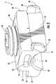
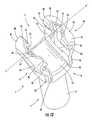
- FIG. 11is an exploded perspective view showing a second modification of the immobilization device according to the present invention.
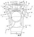
- FIGS. 12 and 13are perspective views showing the osseous anchoring element of the second modification of the immobilization device according to the present invention.
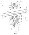
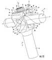
- FIG. 14is a perspective view showing the element for blocking in translation and rotation the connecting rod within the osseous anchoring element of the second modification of the immobilization device according to the present invention.
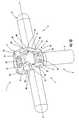
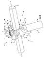
- FIGS. 15 and 16are views showing the elastic deformation of the osseous anchoring element during mounting of the blocking element of the second modification of the immobilization device according to the present invention.
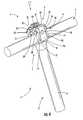
- FIGS. 17 and 18are perspective views showing a second modification of the immobilization device in the assembled position for blocking in rotation and translation the connecting rod of the rachidian implant.
- FIG. 1An immobilization device 1 of a rachidian implant 4 for blocking in rotation and translation a connecting rod 2 in each vertebra belonging to a vertebral column.
- the immobilization device 1is constituted by an osseous anchoring element 3 and a blocking element 5 adapted to coact with the anchoring element 3 to secure in rotation and in translation the connecting rod 2 .
- the osseous anchoring element 3comprising an anchoring portion 6 and a reception portion 7 .
- the anchoring portion 6can have either the form of a hook, or a screw-threaded profile secured or not to the reception portion 7 to be fixed on or in the vertebral body of a vertebra to be equipped.
- the reception portion 7is constituted by a head 8 of U shape open at its upper portion 7 to be able to coact with the connecting rod 2 and the blocking element 5 .
- the head 8comprises two vertical walls 9 , 10 disposed facing each other and in parallel planes so as to delimit a central opening 11 of U shape whose bottom 12 has a part cylindrical profile.
- Each vertical wall 9 , 10is constituted by a central surface 13 bordered laterally and on each side by elastic blades 14 , 15 separated respectively from said central surface by vertical slots 16 , 17 .
- each vertical wall 9 , 10is pierced with a hole 18 opening within the central opening 11 of U shape.
- the elastic blades 14 , 15 of the head 8comprise respectively in their upper portion a tooth 19 , 20 whose external profile 21 , 22 is convexly curved and inclined in the outward direction of each vertical wall 9 , 10 .
- FIG. 3There is shown in FIG. 3 the blocking element 5 of the immobilization device 1 which has an external profile that is substantially parallelepipedal, of which each of the opposite surfaces 23 , 24 ; 25 , 26 , 27 and 28 are parallel two by two.
- the lower surface 24 of the blocking element 5comprises in a direction parallel to the axis XX′ of the connecting rod 2 , a seat 29 having a part cylindrical profile.
- the upper surface 23 of the blocking element 5comprises at its middle a screw-threaded bore 30 opening within the seat 29 and in which coacts a tightening screw 31 .
- the first pair of lateral surfaces 25 , 26 of the blocking element 5comprises respectively above the seat 29 an impression 32 adapted to coact with the teeth of an instrument (not shown) permitting the manipulation and the emplacement of said blocking element on the osseous anchoring element 3 .
- the second pairs of lateral surfaces 27 , 28 of the blocking element 5are each secured to two lugs 33 , 34 disposed in the width of said blocking element, namely in prolongation of each lateral surface 25 , 26 .
- the blocking element 5comprises four lugs 33 , 34 extending in the outward direction of this latter and in a direction perpendicular to the plane containing each lateral surface 27 , 28 .
- Each lug 33 , 34comprises respectively in its lower portion an inclined flat or bevel 35 , 36 directed in the direction of the lateral surfaces 25 , 26 such that the lower base of each inclined flat 35 , 36 will be in the plane containing each of said lateral surfaces 25 , 26 .
- Each lug 33 , 34comprises respectively in its lower portion and opposite the inclined flats 35 , 36 a rounded profile 37 , 38 permitting the sliding of said lugs on said teeth 19 , 20 during assembly of the blocking element 5 with the osseous anchoring element 3 .
- the distance d provided between two lugs 33 , 34 of a same lateral surface 27 , 28is less than that provided between two teeth 19 , 20 of a same vertical wall 9 , 10 of the head 8 of the osseous anchoring element 3 .
- FIGS. 4 and 5There is shown in FIGS. 4 and 5 the emplacement and retention of the blocking element 5 on the head 8 of the anchoring element 3 so as to be able to block in rotation and in translation the connecting rod 2 in each anchored immobilization device 1 of the vertebral body of a vertebra.
- the osseous anchoring element 3is fixed or hooked as a function of its structure to the vertebral body of a vertebra to be equipped.
- the connecting rod 2is positioned within the central opening 11 of the head 8 of the osseous anchoring element 3 .
- the blocking element 5is positioned above the head 8 of the osseous anchoring element 3 such that the lugs 33 , 34 of a same lateral surface 27 , 28 come to bear against the corresponding teeth 19 , 20 of a same vertical wall 9 , 10 .
- a pressure force Fis applied with the help of an instrument (not shown) to the blocking element 5 such that the lugs 33 , 34 of each lateral surface 27 , 28 define laterally the elastic blades 14 , 15 of each wall 9 , 10 of the head 8 of the osseous anchoring element 3 .
- the elastic deformation of the blades 14 , 15takes place in the direction of the central surface 13 of each vertical wall 9 , 10 of the head 8 because of the difference in width provided between the lugs 33 , 34 and the teeth 19 , 20 ( FIG. 4 ).
- each lug 33 , 34has a lower portion of rounded profile 37 , 38 which slides on the external convexly rounded profile 21 , 22 of each tooth 19 , 20 secured to the blades 14 , 15 .
- each lug 33 , 34comes into snap fitting engagement with the corresponding tooth 19 , 20 of the elastic blades 14 , 15 .
- the retention of the lugs 33 , 34is obtained when each inclined flat 35 , 36 coacts with the profile of the corresponding tooth 19 , 20 ( FIG. 5 ).
- the retention of the lugs 33 , 34is obtained by the elasticity of the blades 14 , 15 which return to the rest position after the passage of the lugs 33 , 34 over the corresponding teeth 19 , 20 .
- the connecting rod 2is then immobilized in rotation and in translation by means of the tightening screw 31 which is screwed within the bore 30 of the blocking element 5 .
- the tightening screw 31under the screwing force, blocks the connecting rod 2 against the part cylindrical bottom 12 of the central opening 11 of the head 8 of the anchoring element 3 .
- the tightening force of the pressure screw 31 against the connecting rod 2permits, by means of vertical displacement directed in a direction opposite that of said rod, to block the blocking element 5 in the head 8 of the anchoring element 3 .
- FIGS. 6 to 10There is shown in FIGS. 6 to 10 a first modification of the rachidian implant and more particularly of the immobilization device 1 for the blocking in rotation and translation of the connecting rod 2 in each equipped vertebra of a vertebral column.
- the immobilization device 1is constituted by an osseous anchoring element 3 and a blocking element 5 adapted to coact with the anchoring element 3 for the securement in rotation and in translation of the connecting rod 2 .
- the osseous anchoring element 3comprising an anchoring portion 6 and a reception portion 7 .
- the anchoring portion 6can have either the form of a hook, or a screw-threaded profile secured or not to the reception portion 7 to be fixed on and/or in the vertebral body of a vertebra to be equipped.
- the reception portion 7is constituted by a U shaped head 8 , open in its upper portion to be able to coact with the connection rod 2 and the blocking element 5 .
- the head 8comprises two vertical walls 9 , 10 of truncated profile, disposed one facing the other and in parallel planes so as to delimit a first central opening 11 of U shape carried by the axis XX′ of the connecting rod 2 and whose bottom 12 has a part cylindrical profile, and a second opening 39 perpendicular to the axis XX′ and to the first opening 11 .
- the two perpendicular openings 11 and 39permit delimiting at each angle the head 8 of the retaining means 14 , 15 adapted to deform elastically under the pressure force F.
- Each truncated vertical wall 9 , 10is constituted by a central surface 13 whose height is delimited by the second opening 39 passing through the head 8 of the reception portion 7 .
- Each central surface 13is bordered laterally and on each side by elastic blades 14 , 15 separated respectively from said central surface by vertical slots 16 , 17 .
- each truncated vertical wall 9 , 10is pierced by a blind hole 18 permitting an instrument to hook to permit the introduction of the blocking element 5 in the anchoring element 3 .
- the elastic blades 14 , 15 of the head 8comprise respectively in their upper portion a tooth 19 , 20 whose hooking profile 40 , 41 is turned in the internal direction of the second opening 39 and above the central surface 13 of each vertical wall 9 , 10 .
- Each tooth 19 , 20comprises above its hooking portion 40 , 41 and in the opening direction 39 , an inclined external profile 42 , 43 prolonged in the outward direction of each blade 14 , 15 by a convexly rounded profile 44 , 45 .
- FIG. 8There is shown in FIG. 8 the blocking element 5 of the immobilization device 1 which has a substantially parallelepipedal external profile of which all of the opposite surfaces 23 , 24 ; 25 , 26 , 27 and 28 are parallel two by two.
- the lower surface 24 of the blocking element 5comprises in a direction parallel to the axis XX′ a seat 29 having a part cylindrical profile so as to receive the connecting rod 2 during mounting and securement of the immobilization device 1 .
- the upper surface 23 of the blocking element 5comprises at its middle a screw-threaded bore 30 opening within the seat 29 and in which coacts a tightening screw 31 .
- the blocking element 5comprises two lugs 33 and two lugs 34 which extend in the external direction of this latter.
- Each lug 33 , 34comprises respectively a hooking portion 48 , 49 delimited by an arrangement of inclined and convexly rounded profiles permitting coaction with the hooking portions 40 , 41 of each tooth 19 , 20 during emplacement of the blocking element 5 in the head 8 of the anchoring element 3 .
- each lug 33 , 34are positioned retracted and at a distance d 1 from the lateral and opposed surfaces 25 , 26 of the blocking element 5 .
- Each lug 33 , 34has respectively an inclined external profile 37 , 38 permitting sliding of said lugs and the spacing of the elastic blades 14 , 15 outwardly of the head 8 so as to be able to provide the assembly of the blocking element 5 with the osseous anchoring element 3 .
- FIGS. 9 and 10There is shown in FIGS. 9 and 10 the different steps permitting the assembly of the blocking element 5 in the head 8 of the anchoring element 3 for the securement in rotation and in translation of the connecting rod 2 in each immobilization device 1 anchored in the vertebral body of a vertebra.
- the osseous anchoring element 3is fixed or hooked as a function of its structure to a vertebra to be equipped.
- the connecting rod 2is positioned within the central opening 11 of the head 8 and of the osseous anchoring element 3 before introduction of the blocking element 5 .
- the blocking element 5is positioned above the head 8 of the osseous anchoring element 3 such that the lugs 33 , 34 of a same lateral surface 27 , 28 come to bear against the corresponding teeth 19 , 20 of a same vertical wall 9 , 10 .
- a pressure force Fis produced in a substantially vertical direction, with an instrument (not shown), on the blocking element 5 , so that the lugs 33 , 34 of each lateral surface 27 , 28 deform laterally the elastic blades 14 , 15 of each wall 9 , 10 of the head 8 of the osseous anchoring element 3 .
- the elastic deformation of the blades 14 , 15takes place in an outward direction of the head 8 , which is to say in a direction which spaces the central surface 13 of each vertical wall 9 , 10 from the head 8 , because of the difference of the dimensions provided between the lugs 33 , 34 and the teeth 19 , 20 ( FIG. 9 ).
- each lug 33 , 34has a lower portion with an inclined profile 37 , 38 which slides on the external profile of each tooth 19 , 20 secured to the blades 14 , 15 .
- the pressure force Fmust be sufficient that each hooking portion 48 , 49 of the lugs 33 , 34 comes into snap-fitting engagement with the hooking portion 40 , 41 of each corresponding tooth 19 , 20 of the elastic blades 14 , 15 .
- the retention of the blocking element 5is achieved by the elasticity of the blades 14 , 15 , which return to the rest position after the passage of the lugs 33 , 34 over the corresponding teeth 19 , 20 .
- connection rod 2is adjusted by sliding in a cylindrical trough constituted by the bottom 12 having a part cylindrical profile of the head 8 of the osseous anchoring element 3 and the seat 29 having a part cylindrical profile of the blocking element 5 .
- the connecting rod 2is then immobilized in rotation and in translation by means of the tightening screw 31 which is screwed within the bore 30 of the blocking element 5 .
- the tightening screw 31under the screwing force, blocks the connecting rod 2 against the part cylindrical bottom 12 of the central opening 11 of the head 8 of the anchoring element 3 .
- the tightening force of the pressure screw 31 against the connecting rod 2permits, by means of vertical movement directed in a direction opposite that of said rod, to block the blocking element 5 in the head 8 of the anchoring element 3 .
- FIGS. 11 to 18There is shown in FIGS. 11 to 18 a second modification of the rachidian implant and more particularly of the immobilization device 1 for blocking in rotation and translation a connecting rod 2 in each equipped vertebra of a vertebral column.
- the immobilization device 1is constituted by an osseous anchoring element 3 and a blocking element 5 adapted to coact with the anchoring element 3 for the securement in rotation and in translation of the connecting rod 2 .
- the osseous anchoring element 3comprises an anchoring portion 6 and a reception portion 7 .
- the anchoring portion 6can have either the form of a hook, or a screw-threaded profile secured or not to the reception portion 7 to be fixed on or in the vertebra to be equipped.
- the reception portion 7is constituted by a U shaped head 8 open in its upper portion to be able to coact with the connection rod 2 and the blocking element 5 .
- the head 8comprises two vertical walls 9 , 10 disposed facing each other and in parallel planes so as to delimit a first central U shaped opening 11 carried by the axis XX′ of the connecting rod 2 and whose bottom 12 has a part cylindrical profile.
- Each vertical wall 9 , 10is separated from the bottom 12 of the central opening 11 by a vertical slot 50 imparting a certain elasticity to each wall in a direction YY′ perpendicular to the direction XX′ of the connecting rod 2 .
- the elastic vertical walls 9 , 10comprise respectively at each end a profile in the form of a hooking blade 14 , 15 disposed facing each other on opposite sides of the central opening 11 .
- Each elastic vertical wall 9 , 10comprises on its internal surface and between the hooking blades 14 , 15 , a vertical seat 51 having a part-cylindrical profile.
- the vertical seat 51has on each side a groove 54 permitting guiding the blocking element 5 during its emplacement within the U shaped head 8 .
- Each elastic vertical wall 9 , 10is pierced between the hooking blades 14 , 15 by a hole 18 opening within the central opening 11 permitting an instrument to hook to permit the introduction of the blocking element 5 in the anchoring element 3 .
- the hooking blades 14 , 15 of the head 8comprise respectively in the upper portion a tooth 19 , 20 whose hooking profile 40 , 41 is turned in the direction of the interior of the central opening 11 .
- Each tooth 19 , 20comprises above its hooking portion 40 , 41 an inclined external portion 42 , 43 prolonged in the outward direction of each blade 14 , 15 by a convexly rounded profile 44 , 45 .
- FIG. 14There is shown in FIG. 14 the blocking element 5 of the immobilization device 1 which has a substantially parallelepipedal external profile of which all of the opposite surfaces 23 , 24 ; 25 , 26 , 27 and 28 are parallel two by two.
- the surface 24 of the blocking element 5comprises in a direction parallel to the axis XX′ a seat 29 having a part cylindrical profile so as to receive the connecting rod 2 during mounting and securement of the immobilization device 1 .
- the upper surface 23 of the blocking element 5comprises at its middle a screw-threaded bore 30 opening within the seat 29 and in which coacts a tightening screw 31 .
- the blocking element 5comprises two lugs 33 and two lugs 34 which extend in the outward direction of this latter.
- Each lug 33 , 34comprises respectively a hooking portion 48 , 49 delimited by a cylindrical profile portion permitting coaction with the hooking portions 40 , 41 of each tooth 19 , 20 during emplacement of the blocking element 5 in the head 8 of the anchoring element 3 ( FIG. 15 ).
- Each lug 33 , 34has respectively an inclined external profile 37 , 38 permitting sliding of said lugs and the elastic spacing of the walls 9 , 10 and hence of the hooking blades 14 , 15 in the direction YY′ so as to be able to effect the assembly of the blocking element 5 with the osseous anchoring element 3 .
- each opposite surface 27 , 28comprises at its middle and between the lugs 33 , 34 a vertical recess 52 bordered laterally by ribs 53 permitting the guidance of the blocking element 5 during its introduction into the head 8 of the anchoring element 3 .
- hooking portions 48 , 49are closed opposite the lateral surfaces 25 , 26 by means of the corresponding vertical rib 53 and disposed between each lugs 33 , 34 .
- Each vertical rib 53can have an external profile of any shape, provided that its profile will be complementary to that of the groove 54 provided in the thickness of the external surface of each vertical wall 9 , 10 of the head 8 of the anchoring element 3 .
- the vertical seats 51 and 52have a complementary part cylindrical profile so as to permit the introduction of an instrument so as to ensure the retraction of the blocking element 5 of the head 8 of the anchoring element 3 .
- FIGS. 15 to 18There is shown in FIGS. 15 to 18 the different steps permitting the assembly of the blocking element 5 in the head 8 of the anchoring element 3 for the securement in rotation and in translation of the connecting rod 2 in each immobilization device 1 anchored in the vertebral body of a vertebra.
- connection rod 2is positioned within the central opening 11 of the head 8 of the osseous anchoring element 3 before the introduction of the blocking element 5 .
- the blocking element 5is positioned above the head 8 of the osseous anchoring element 3 such that the lugs 33 , 34 of a same lateral surface 27 , 28 come to bear against the corresponding teeth 19 , 20 of a same vertical wall 9 , 10 .
- a pressure force Fis generated in a substantially vertical direction with an instrument (not shown), on the blocking element 5 , so that the lugs 33 , 34 of each lateral surface 27 , 28 deform laterally the vertical walls 9 , 10 and hence the elastic hooking blades 14 , 15 .
- the elastic deformation of the vertical walls 9 , 10takes place in the external direction of the head 8 because of the difference of dimensions provided between the lugs 33 , 34 and the teeth 19 , 20 .
- each lug 33 , 34has a lower portion of inclined profile 37 , 38 which slides on the external profile of each tooth 19 , 20 of the hooking blades 14 , 15 of each elastic wall 9 , 10 .
- the pressure force Fmust be sufficient that each hooking portion 48 , 49 of the lugs 33 , 34 will come into snap fitting engagement with the hooking portion 40 , 41 of each corresponding tooth 19 , 20 .
- the retention of the blocking element 5is achieved by the elasticity of the vertical walls 9 , 10 and hence of the hooking blades 14 , 15 , which return to the rest position after the passage of the lugs 33 , 34 over the corresponding teeth 19 , 20 .
- the connecting rod 2is adjusted by sliding in a cylindrical trough constituted by the part cylindrical bottom 12 of the head 8 of the osseous anchoring element 3 and the seat 29 having a part cylindrical profile of the blocking element 5 .
- the connecting rod 2is then immobilized in rotation and in translation by means of the tightening screw 31 which is screwed into the bore 30 of the blocking element 5 .
- the tightening screw 31under the screwing force, blocks the connecting rod against the part cylindrical bottom 12 of the central opening 11 of the head 8 of the anchoring element 3 .
- the screwing force of the pressure screw 31 against the connecting rod 2permits, by means of vertical movement directed in a direction opposite that of said rod, to block the blocking element 5 in the head 8 of the anchoring element 3 .
- the retraction of the blocking element 5is achieved by means of an instrument which is introduced into the vertical seats 51 and 52 so as to space apart the vertical walls 9 , 10 in the outward direction of the head 8 of the anchoring element 3 .
Landscapes
- Health & Medical Sciences (AREA)
- Orthopedic Medicine & Surgery (AREA)
- Surgery (AREA)
- Life Sciences & Earth Sciences (AREA)
- Neurology (AREA)
- Medical Informatics (AREA)
- Biomedical Technology (AREA)
- Heart & Thoracic Surgery (AREA)
- Engineering & Computer Science (AREA)
- Molecular Biology (AREA)
- Animal Behavior & Ethology (AREA)
- General Health & Medical Sciences (AREA)
- Public Health (AREA)
- Veterinary Medicine (AREA)
- Nuclear Medicine, Radiotherapy & Molecular Imaging (AREA)
- Surgical Instruments (AREA)
- Prostheses (AREA)
Abstract
Description
- an osseous anchoring element provided with a head comprising two vertical walls delimiting a central opening of U shape whose bottom has a part cylindrical profile, each vertical wall being constituted by a central surface bordered laterally and on each side by elastic blades separated respectively from said central surface by vertical slots, said elastic blades comprising respectively in their upper portion a snap-in tooth,
- and a blocking element comprising a seat with a part cylindrical profile, a screw-threaded bore opening within the seat, a tightening screw coacting with the screw-threaded bore and lugs which coact respectively with a tooth secured to elastic blades.
- an osseous anchoring element provided with a head comprising two vertical truncated walls delimiting a central opening of U shape whose bottom has a part cylindrical profile, each vertical wall being constituted by a central surface bordered laterally and on each side by elastic blades separated respectively from said central surface by vertical slots, said elastic blades comprising respectively in their upper portion a snap-in tooth,
- and a blocking element comprising a seat with a part cylindrical profile, a screw-threaded bore opening within the seat, a tightening screw coacting with the screw-threaded bore and lugs which coact respectively with a tooth secured to the elastic blades.
- an osseous anchoring element provided with a head comprising two vertical walls delimiting a central opening of U shape whose bottom has a part cylindrical profile, each vertical wall being separated from the bottom of the central opening by a vertical slot giving a certain elasticity to each wall in a direction YY′, said vertical walls comprising respectively at each end a profile in the form of an elastic hooking blade disposed one facing the other and on opposite sides of the central opening, said elastic blades comprising respectively in their upper portion a snap-in tooth,
- and a blocking element comprising a seat with a part cylindrical profile, a screw-threaded bore opening within the seat, a tightening screw coacting with the screw-threaded bore, and lugs which coact respectively with a tooth secured to the elastic blades.
Claims (20)
Applications Claiming Priority (4)
| Application Number | Priority Date | Filing Date | Title |
|---|---|---|---|
| FR0216441AFR2848808B1 (en) | 2002-12-23 | 2002-12-23 | DEVICE FOR IMMOBILIZATION OF A CONNECTING ROD IN A BONE ANCHORING ELEMENT OF A SPINAL IMPLANT |
| FR0216441 | 2002-12-23 | ||
| FR0308701 | 2003-07-17 | ||
| FR0308701AFR2857577B1 (en) | 2003-07-17 | 2003-07-17 | IMPROVEMENTS TO SPARK IMMOBILIZATION DEVICES |
Publications (2)
| Publication Number | Publication Date |
|---|---|
| US20050027292A1 US20050027292A1 (en) | 2005-02-03 |
| US8328850B2true US8328850B2 (en) | 2012-12-11 |
Family
ID=32773877
Family Applications (1)
| Application Number | Title | Priority Date | Filing Date |
|---|---|---|---|
| US10/682,541Active2027-12-06US8328850B2 (en) | 2002-12-23 | 2003-10-10 | Device for immobilizing a connecting rod in an osseous anchoring element of a rachidian implant |
Country Status (9)
| Country | Link |
|---|---|
| US (1) | US8328850B2 (en) |
| EP (1) | EP1578288B1 (en) |
| JP (1) | JP4493599B2 (en) |
| KR (1) | KR20050088321A (en) |
| AT (1) | ATE369805T1 (en) |
| AU (1) | AU2003285398A1 (en) |
| DE (1) | DE60315713T2 (en) |
| ES (1) | ES2291715T3 (en) |
| WO (1) | WO2004064653A1 (en) |
Cited By (16)
| Publication number | Priority date | Publication date | Assignee | Title |
|---|---|---|---|---|
| US20110160779A1 (en)* | 2008-09-05 | 2011-06-30 | Synthes Usa, Llc | Bone fixation assembly |
| US8790374B2 (en) | 2004-04-08 | 2014-07-29 | Globus Medical, Inc. | Polyaxial screw |
| US8888827B2 (en) | 2011-07-15 | 2014-11-18 | Globus Medical, Inc. | Orthopedic fixation devices and methods of installation thereof |
| US9186187B2 (en) | 2011-07-15 | 2015-11-17 | Globus Medical, Inc. | Orthopedic fixation devices and methods of installation thereof |
| US9198694B2 (en) | 2011-07-15 | 2015-12-01 | Globus Medical, Inc. | Orthopedic fixation devices and methods of installation thereof |
| US9259254B2 (en) | 2004-04-08 | 2016-02-16 | Globus Medical, Inc. | Polyaxial screw |
| US9358047B2 (en) | 2011-07-15 | 2016-06-07 | Globus Medical, Inc. | Orthopedic fixation devices and methods of installation thereof |
| US20170105766A1 (en)* | 2015-10-14 | 2017-04-20 | Alphatec Spine, Inc. | Polyaxial Bone Screw and Bushing |
| US9993269B2 (en) | 2011-07-15 | 2018-06-12 | Globus Medical, Inc. | Orthopedic fixation devices and methods of installation thereof |
| US11129651B1 (en)* | 2020-03-31 | 2021-09-28 | Warsaw Orthopedic, Inc. | Pop-on-cap assemblies having opposing splay-resisting features and opposing anti-rotation features for spinal surgery |
| US20220233215A1 (en)* | 2019-12-20 | 2022-07-28 | Warsaw Orthopedic Inc. | Anti-splay head and set screw for spinal fixation |
| US11627995B2 (en) | 2020-12-21 | 2023-04-18 | Warsaw Orthopedic, Inc. | Locking-cap module and connector |
| US11627992B2 (en) | 2020-12-21 | 2023-04-18 | Warsaw Orthopedic, Inc. | Locking-cap module and connector |
| US20230240724A1 (en)* | 2019-05-22 | 2023-08-03 | Nuvasive, Inc. | Posterior spinal fixation screws |
| US11957391B2 (en) | 2021-11-01 | 2024-04-16 | Warsaw Orthopedic, Inc. | Bone screw having an overmold of a shank |
| US12329419B2 (en) | 2020-03-31 | 2025-06-17 | Warsaw Orthopedic, Inc | Pop-on-cap assemblies having opposing splay-resisting features and generally demi-teardrop opposing rotation-preventing/rotation-resisting features for spinal surgery |
Families Citing this family (28)
| Publication number | Priority date | Publication date | Assignee | Title |
|---|---|---|---|---|
| US8353932B2 (en)* | 2005-09-30 | 2013-01-15 | Jackson Roger P | Polyaxial bone anchor assembly with one-piece closure, pressure insert and plastic elongate member |
| US7658582B2 (en) | 2003-07-09 | 2010-02-09 | Ortho Innovations, Llc | Precise linear fastener system and method for use |
| US7842073B2 (en)* | 2002-04-18 | 2010-11-30 | Aesculap Ii, Inc. | Screw and rod fixation assembly and device |
| US6740086B2 (en) | 2002-04-18 | 2004-05-25 | Spinal Innovations, Llc | Screw and rod fixation assembly and device |
| US7621918B2 (en)* | 2004-11-23 | 2009-11-24 | Jackson Roger P | Spinal fixation tool set and method |
| US7588575B2 (en)* | 2003-10-21 | 2009-09-15 | Innovative Spinal Technologies | Extension for use with stabilization systems for internal structures |
| US7967826B2 (en)* | 2003-10-21 | 2011-06-28 | Theken Spine, Llc | Connector transfer tool for internal structure stabilization systems |
| WO2005063135A1 (en)* | 2003-12-23 | 2005-07-14 | Eurosurgical | Surgical instrument that can be unclipped and is used for a spinal implant |
| US7763049B2 (en) | 2004-06-09 | 2010-07-27 | Zimmer Spine, Inc. | Orthopedic fixation connector |
| US8361129B2 (en)* | 2006-04-28 | 2013-01-29 | Depuy Spine, Inc. | Large diameter bone anchor assembly |
| US9232968B2 (en)* | 2007-12-19 | 2016-01-12 | DePuy Synthes Products, Inc. | Polymeric pedicle rods and methods of manufacturing |
| KR100952753B1 (en)* | 2008-03-27 | 2010-04-14 | 주식회사 지에스메디칼 | Dynamic load |
| US20090326583A1 (en)* | 2008-06-25 | 2009-12-31 | Missoum Moumene | Posterior Dynamic Stabilization System With Flexible Ligament |
| US20090326584A1 (en)* | 2008-06-27 | 2009-12-31 | Michael Andrew Slivka | Spinal Dynamic Stabilization Rods Having Interior Bumpers |
| US20100004693A1 (en)* | 2008-07-01 | 2010-01-07 | Peter Thomas Miller | Cam locking spine stabilization system and method |
| US8118837B2 (en)* | 2008-07-03 | 2012-02-21 | Zimmer Spine, Inc. | Tapered-lock spinal rod connectors and methods for use |
| US8167914B1 (en) | 2008-07-16 | 2012-05-01 | Zimmer Spine, Inc. | Locking insert for spine stabilization and method of use |
| US8197512B1 (en)* | 2008-07-16 | 2012-06-12 | Zimmer Spine, Inc. | System and method for spine stabilization using resilient inserts |
| US8641734B2 (en)* | 2009-02-13 | 2014-02-04 | DePuy Synthes Products, LLC | Dual spring posterior dynamic stabilization device with elongation limiting elastomers |
| US9320543B2 (en)* | 2009-06-25 | 2016-04-26 | DePuy Synthes Products, Inc. | Posterior dynamic stabilization device having a mobile anchor |
| KR20120051692A (en)* | 2009-07-16 | 2012-05-22 | 스파인세이브 아게 | Spinal implant set including a quick closure |
| US8361123B2 (en) | 2009-10-16 | 2013-01-29 | Depuy Spine, Inc. | Bone anchor assemblies and methods of manufacturing and use thereof |
| US9445844B2 (en)* | 2010-03-24 | 2016-09-20 | DePuy Synthes Products, Inc. | Composite material posterior dynamic stabilization spring rod |
| FR2991568B1 (en)* | 2012-06-07 | 2014-07-04 | Euros Sa | ILIO-SACRE IMPLANT CONNECTING TO A SYSTEM OF SPINAL OSTEOSYNTHESIS |
| US9510863B2 (en) | 2012-07-02 | 2016-12-06 | Spectrum Spine Ip Holdings, Llc | Bone screw coupling assembly |
| US8491640B1 (en)* | 2012-07-02 | 2013-07-23 | James C. Robinson | Bone screw coupling assembly |
| CN107693098B (en)* | 2017-10-31 | 2024-02-06 | 李照文 | Anti-loosening pedicle screw rod system |
| US20250186088A1 (en)* | 2021-08-26 | 2025-06-12 | Orthopediatrics Corp. | Guided growth spinal implants |
Citations (18)
| Publication number | Priority date | Publication date | Assignee | Title |
|---|---|---|---|---|
| FR2697992A1 (en) | 1992-11-18 | 1994-05-20 | Eurosurgical | Device for fixation on a stem of an organ, in particular for spinal orthopedic instrumentation. |
| US5346493A (en)* | 1991-10-04 | 1994-09-13 | Acromed Corporation | Top-entry rod retainer |
| FR2729291A1 (en) | 1995-01-12 | 1996-07-19 | Euros Sa | RACHIDIAN IMPLANT |
| US6077262A (en)* | 1993-06-04 | 2000-06-20 | Synthes (U.S.A.) | Posterior spinal implant |
| US6090111A (en)* | 1998-06-17 | 2000-07-18 | Surgical Dynamics, Inc. | Device for securing spinal rods |
| US6110172A (en)* | 1998-07-31 | 2000-08-29 | Jackson; Roger P. | Closure system for open ended osteosynthesis apparatus |
| EP1064885A1 (en) | 1999-07-02 | 2001-01-03 | Sulzer Orthopedics Ltd. | Spinal fixator |
| FR2795623A1 (en) | 1999-07-01 | 2001-01-05 | Gerard Vanacker | SYSTEM FOR OSTEOSYNTHESIS ON THE VERTEBRAL COLUMN, ESPECIALLY FOR STABILIZATION OF VERTEBRATES, FASTENING ELEMENT AND ANCILLARY FOR SUCH A SYSTEM |
| DE19951145A1 (en) | 1999-10-23 | 2001-05-31 | Schaefer Micomed Gmbh | Osteosynthetic device has bone-screw, with fork head with groove for holding correction bar, notches , snap-on cap, lugs and holders |
| US6302888B1 (en)* | 1999-03-19 | 2001-10-16 | Interpore Cross International | Locking dovetail and self-limiting set screw assembly for a spinal stabilization member |
| EP1190678A2 (en) | 2000-09-22 | 2002-03-27 | DePuy Acromed, Inc. | Lock cap anchor assembly for orthopaedic fixation |
| US6540749B2 (en)* | 2001-02-17 | 2003-04-01 | Bernd Schäfer | Bone screw |
| US6565565B1 (en)* | 1998-06-17 | 2003-05-20 | Howmedica Osteonics Corp. | Device for securing spinal rods |
| US6585737B1 (en)* | 1998-04-30 | 2003-07-01 | Stryker Spine | Backbone osteosynthesis system with collar and lock |
| US20040097933A1 (en)* | 2002-11-19 | 2004-05-20 | Rodolphe Lourdel | Vertebral anchoring device and its blocking device on a polyaxial screw |
| US6740086B2 (en)* | 2002-04-18 | 2004-05-25 | Spinal Innovations, Llc | Screw and rod fixation assembly and device |
| US6786903B2 (en)* | 2002-01-24 | 2004-09-07 | A-Spine Holding Group Corp. | Rotary device for fixing spinal column under treatment |
| US6896877B2 (en)* | 1997-12-15 | 2005-05-24 | Revlon Consumer Products Corporation | Cosmetic compositions containing crosslinkable polymers |
Family Cites Families (1)
| Publication number | Priority date | Publication date | Assignee | Title |
|---|---|---|---|---|
| WO1995013755A1 (en)* | 1993-11-19 | 1995-05-26 | Cross Medical Products, Inc. | Rod anchor seat having sliding closure member |
- 2003
- 2003-10-10USUS10/682,541patent/US8328850B2/enactiveActive
- 2003-10-14DEDE60315713Tpatent/DE60315713T2/ennot_activeExpired - Lifetime
- 2003-10-14WOPCT/FR2003/003023patent/WO2004064653A1/enactiveIP Right Grant
- 2003-10-14ESES03778390Tpatent/ES2291715T3/ennot_activeExpired - Lifetime
- 2003-10-14AUAU2003285398Apatent/AU2003285398A1/ennot_activeAbandoned
- 2003-10-14JPJP2005512886Apatent/JP4493599B2/ennot_activeExpired - Lifetime
- 2003-10-14ATAT03778390Tpatent/ATE369805T1/ennot_activeIP Right Cessation
- 2003-10-14EPEP03778390Apatent/EP1578288B1/ennot_activeExpired - Lifetime
- 2003-10-14KRKR1020057011720Apatent/KR20050088321A/ennot_activeAbandoned
Patent Citations (20)
| Publication number | Priority date | Publication date | Assignee | Title |
|---|---|---|---|---|
| US5346493A (en)* | 1991-10-04 | 1994-09-13 | Acromed Corporation | Top-entry rod retainer |
| FR2697992A1 (en) | 1992-11-18 | 1994-05-20 | Eurosurgical | Device for fixation on a stem of an organ, in particular for spinal orthopedic instrumentation. |
| US6077262A (en)* | 1993-06-04 | 2000-06-20 | Synthes (U.S.A.) | Posterior spinal implant |
| FR2729291A1 (en) | 1995-01-12 | 1996-07-19 | Euros Sa | RACHIDIAN IMPLANT |
| US6896877B2 (en)* | 1997-12-15 | 2005-05-24 | Revlon Consumer Products Corporation | Cosmetic compositions containing crosslinkable polymers |
| US6585737B1 (en)* | 1998-04-30 | 2003-07-01 | Stryker Spine | Backbone osteosynthesis system with collar and lock |
| US6090111A (en)* | 1998-06-17 | 2000-07-18 | Surgical Dynamics, Inc. | Device for securing spinal rods |
| US6565565B1 (en)* | 1998-06-17 | 2003-05-20 | Howmedica Osteonics Corp. | Device for securing spinal rods |
| US6110172A (en)* | 1998-07-31 | 2000-08-29 | Jackson; Roger P. | Closure system for open ended osteosynthesis apparatus |
| US6302888B1 (en)* | 1999-03-19 | 2001-10-16 | Interpore Cross International | Locking dovetail and self-limiting set screw assembly for a spinal stabilization member |
| FR2795623A1 (en) | 1999-07-01 | 2001-01-05 | Gerard Vanacker | SYSTEM FOR OSTEOSYNTHESIS ON THE VERTEBRAL COLUMN, ESPECIALLY FOR STABILIZATION OF VERTEBRATES, FASTENING ELEMENT AND ANCILLARY FOR SUCH A SYSTEM |
| EP1064885A1 (en) | 1999-07-02 | 2001-01-03 | Sulzer Orthopedics Ltd. | Spinal fixator |
| DE19951145A1 (en) | 1999-10-23 | 2001-05-31 | Schaefer Micomed Gmbh | Osteosynthetic device has bone-screw, with fork head with groove for holding correction bar, notches , snap-on cap, lugs and holders |
| EP1190678A2 (en) | 2000-09-22 | 2002-03-27 | DePuy Acromed, Inc. | Lock cap anchor assembly for orthopaedic fixation |
| US6755829B1 (en)* | 2000-09-22 | 2004-06-29 | Depuy Acromed, Inc. | Lock cap anchor assembly for orthopaedic fixation |
| US20050033296A1 (en)* | 2000-09-22 | 2005-02-10 | Bono Frank Scott | Locking cap assembly for spinal fixation instrumentation |
| US6540749B2 (en)* | 2001-02-17 | 2003-04-01 | Bernd Schäfer | Bone screw |
| US6786903B2 (en)* | 2002-01-24 | 2004-09-07 | A-Spine Holding Group Corp. | Rotary device for fixing spinal column under treatment |
| US6740086B2 (en)* | 2002-04-18 | 2004-05-25 | Spinal Innovations, Llc | Screw and rod fixation assembly and device |
| US20040097933A1 (en)* | 2002-11-19 | 2004-05-20 | Rodolphe Lourdel | Vertebral anchoring device and its blocking device on a polyaxial screw |
Cited By (30)
| Publication number | Priority date | Publication date | Assignee | Title |
|---|---|---|---|---|
| US9179937B2 (en) | 2004-04-08 | 2015-11-10 | Globus Medical, Inc. | Polyaxial screw |
| US8790374B2 (en) | 2004-04-08 | 2014-07-29 | Globus Medical, Inc. | Polyaxial screw |
| US9259254B2 (en) | 2004-04-08 | 2016-02-16 | Globus Medical, Inc. | Polyaxial screw |
| US8894691B2 (en) | 2004-04-08 | 2014-11-25 | Globus Medical, Inc. | Polyaxial screw |
| US9282998B2 (en)* | 2008-09-05 | 2016-03-15 | DePuy Synthes Products, Inc. | Bone fixation assembly |
| US12251137B2 (en) | 2008-09-05 | 2025-03-18 | DePuy Synthes Products, Inc. | Bone fixation assembly |
| US11134992B2 (en) | 2008-09-05 | 2021-10-05 | DePuy Synthes Products, Inc. | Bone fixation assembly |
| US10357287B2 (en) | 2008-09-05 | 2019-07-23 | DePuy Synthes Products, Inc. | Bone fixation assembly |
| US11812998B2 (en) | 2008-09-05 | 2023-11-14 | DePuy Synthes Products, Inc. | Bone fixation assembly |
| US20110160779A1 (en)* | 2008-09-05 | 2011-06-30 | Synthes Usa, Llc | Bone fixation assembly |
| US9872710B2 (en) | 2008-09-05 | 2018-01-23 | DePuy Synthes Products, Inc. | Bone fixation assembly |
| US9186187B2 (en) | 2011-07-15 | 2015-11-17 | Globus Medical, Inc. | Orthopedic fixation devices and methods of installation thereof |
| US9549763B2 (en) | 2011-07-15 | 2017-01-24 | Globus Medical, Inc. | Orthopedic fixation devices and methods of installation thereof |
| US9993269B2 (en) | 2011-07-15 | 2018-06-12 | Globus Medical, Inc. | Orthopedic fixation devices and methods of installation thereof |
| US9358047B2 (en) | 2011-07-15 | 2016-06-07 | Globus Medical, Inc. | Orthopedic fixation devices and methods of installation thereof |
| US8888827B2 (en) | 2011-07-15 | 2014-11-18 | Globus Medical, Inc. | Orthopedic fixation devices and methods of installation thereof |
| US11090087B2 (en) | 2011-07-15 | 2021-08-17 | Globus Medical, Inc. | Orthopedic fixation devices and methods of installation thereof |
| US12245795B2 (en) | 2011-07-15 | 2025-03-11 | Globus Medical, Inc. | Orthopedic fixation devices and methods of installation thereof |
| US9198694B2 (en) | 2011-07-15 | 2015-12-01 | Globus Medical, Inc. | Orthopedic fixation devices and methods of installation thereof |
| US10098669B2 (en)* | 2015-10-14 | 2018-10-16 | Alphatec Spine, Inc. | Polyaxial bone screw and bushing |
| US20170105766A1 (en)* | 2015-10-14 | 2017-04-20 | Alphatec Spine, Inc. | Polyaxial Bone Screw and Bushing |
| US20230240724A1 (en)* | 2019-05-22 | 2023-08-03 | Nuvasive, Inc. | Posterior spinal fixation screws |
| US20220233215A1 (en)* | 2019-12-20 | 2022-07-28 | Warsaw Orthopedic Inc. | Anti-splay head and set screw for spinal fixation |
| US12171466B2 (en)* | 2019-12-20 | 2024-12-24 | Warsaw Orthopedic Inc. | Anti-splay head and set screw for spinal fixation |
| US20210401473A1 (en)* | 2020-03-31 | 2021-12-30 | Warsaw Orthopedic Inc. | Pop-on-cap assemblies having opposing splay-resisting features and opposing anti-rotation features for spinal surgery |
| US11129651B1 (en)* | 2020-03-31 | 2021-09-28 | Warsaw Orthopedic, Inc. | Pop-on-cap assemblies having opposing splay-resisting features and opposing anti-rotation features for spinal surgery |
| US12329419B2 (en) | 2020-03-31 | 2025-06-17 | Warsaw Orthopedic, Inc | Pop-on-cap assemblies having opposing splay-resisting features and generally demi-teardrop opposing rotation-preventing/rotation-resisting features for spinal surgery |
| US11627995B2 (en) | 2020-12-21 | 2023-04-18 | Warsaw Orthopedic, Inc. | Locking-cap module and connector |
| US11627992B2 (en) | 2020-12-21 | 2023-04-18 | Warsaw Orthopedic, Inc. | Locking-cap module and connector |
| US11957391B2 (en) | 2021-11-01 | 2024-04-16 | Warsaw Orthopedic, Inc. | Bone screw having an overmold of a shank |
Also Published As
| Publication number | Publication date |
|---|---|
| AU2003285398A1 (en) | 2004-08-13 |
| JP4493599B2 (en) | 2010-06-30 |
| EP1578288A1 (en) | 2005-09-28 |
| EP1578288B1 (en) | 2007-08-15 |
| US20050027292A1 (en) | 2005-02-03 |
| JP2006512183A (en) | 2006-04-13 |
| KR20050088321A (en) | 2005-09-05 |
| DE60315713D1 (en) | 2007-09-27 |
| DE60315713T2 (en) | 2008-06-05 |
| ATE369805T1 (en) | 2007-09-15 |
| ES2291715T3 (en) | 2008-03-01 |
| WO2004064653A1 (en) | 2004-08-05 |
Similar Documents
| Publication | Publication Date | Title |
|---|---|---|
| US8328850B2 (en) | Device for immobilizing a connecting rod in an osseous anchoring element of a rachidian implant | |
| US12429251B2 (en) | Multi-level mounting system | |
| US20050240180A1 (en) | Spinal osteosynthesis system comprising a support pad | |
| EP1080292B1 (en) | Automotive deck lid bumper | |
| US6371957B1 (en) | Device for connecting a longitudinal bar to a pedicle screw | |
| US5873878A (en) | Anchoring member | |
| US6302888B1 (en) | Locking dovetail and self-limiting set screw assembly for a spinal stabilization member | |
| US7597707B2 (en) | Pedicle screw with a closure device for the fixing of elastic rod elements | |
| US5412876A (en) | Protective cap for the end of a level having an I-shaped cross-section | |
| US20040254579A1 (en) | Bone connection device | |
| US9077167B2 (en) | Aircraft raceway mounting and clamping apparatus | |
| US20060052781A1 (en) | Clamp for multiple rod-shaped elements | |
| JP2003509093A (en) | Osteosynthesis device | |
| KR20130046369A (en) | High angulation polyaxial bone anchoring device | |
| JP2005526202A (en) | Support system for solar panel | |
| US9055983B1 (en) | Self-locking bone screw receiver | |
| KR102050670B1 (en) | Rail stopper for sliding windows and doors | |
| US11259850B2 (en) | Femur fixation apparatus | |
| CN114198374A (en) | A connecting system for connecting at least two, in particular plate-like, elements; assembly comprising such a connection system | |
| CN110886757A (en) | Anti-vibration quick-release lock | |
| AU714305B2 (en) | Clamping device for detachably connecting two profiled parts | |
| GB2103327A (en) | Fixing means for hollow elongate members | |
| ES2931512T3 (en) | Fixing wedge and electrical cabinet comprising said wedge | |
| EP0674082B1 (en) | An adjustment device, in particular for metal frames | |
| US20100092239A1 (en) | Fixing element and apparatus for accommodating a fixing element |
Legal Events
| Date | Code | Title | Description |
|---|---|---|---|
| AS | Assignment | Owner name:EUROSURGICAL SA, FRANCE Free format text:ASSIGNMENT OF ASSIGNORS INTEREST;ASSIGNORS:BERNARD, PIERRE;LEPORT, TIPHAINE;LEROY, JEAN-YVES;AND OTHERS;REEL/FRAME:014598/0091 Effective date:20031010 | |
| AS | Assignment | Owner name:ORTHOTEC, LLC, CALIFORNIA Free format text:ASSIGNMENT OF ASSIGNORS INTEREST;ASSIGNOR:EUROSURGICAL S.A.;REEL/FRAME:016188/0832 Effective date:20040827 | |
| AS | Assignment | Owner name:CHOICE SPINE, LP, TENNESSEE Free format text:ASSIGNMENT OF ASSIGNORS INTEREST;ASSIGNOR:ORTHOTEC, LLC;REEL/FRAME:021243/0197 Effective date:20080630 | |
| STCF | Information on status: patent grant | Free format text:PATENTED CASE | |
| FPAY | Fee payment | Year of fee payment:4 | |
| AS | Assignment | Owner name:CHOICE SPINE, LLC, TENNESSEE Free format text:CONVERSION OF ENTITY;ASSIGNOR:CHOICE SPINE, LP;REEL/FRAME:048147/0243 Effective date:20181119 | |
| AS | Assignment | Owner name:ABACUS FINANCE GROUP, LLC, NEW YORK Free format text:SECURITY INTEREST;ASSIGNOR:CHOICE SPINE, LLC;REEL/FRAME:047618/0524 Effective date:20181119 | |
| MAFP | Maintenance fee payment | Free format text:PAYMENT OF MAINTENANCE FEE, 8TH YR, SMALL ENTITY (ORIGINAL EVENT CODE: M2552); ENTITY STATUS OF PATENT OWNER: SMALL ENTITY Year of fee payment:8 | |
| MAFP | Maintenance fee payment | Free format text:PAYMENT OF MAINTENANCE FEE, 12TH YR, SMALL ENTITY (ORIGINAL EVENT CODE: M2553); ENTITY STATUS OF PATENT OWNER: SMALL ENTITY Year of fee payment:12 |