US8328848B2 - Interspinous vertebral stabilization devices - Google Patents
Interspinous vertebral stabilization devicesDownload PDFInfo
- Publication number
- US8328848B2 US8328848B2US11/535,210US53521006AUS8328848B2US 8328848 B2US8328848 B2US 8328848B2US 53521006 AUS53521006 AUS 53521006AUS 8328848 B2US8328848 B2US 8328848B2
- Authority
- US
- United States
- Prior art keywords
- bone
- vertebra
- legs
- devices
- rod
- Prior art date
- Legal status (The legal status is an assumption and is not a legal conclusion. Google has not performed a legal analysis and makes no representation as to the accuracy of the status listed.)
- Expired - Fee Related, expires
Links
- 230000006641stabilisationEffects0.000titleclaimsabstractdescription16
- 238000011105stabilizationMethods0.000titleclaimsabstractdescription16
- 238000000034methodMethods0.000claimsabstractdescription65
- 230000008569processEffects0.000claimsabstractdescription46
- 210000000988bone and boneAnatomy0.000claimsdescription68
- 238000003780insertionMethods0.000claimsdescription10
- 230000037431insertionEffects0.000claimsdescription10
- 238000000576coating methodMethods0.000claimsdescription8
- 229910052751metalInorganic materials0.000claimsdescription8
- 239000002184metalSubstances0.000claimsdescription8
- 229920000642polymerPolymers0.000claimsdescription6
- 239000011248coating agentSubstances0.000claimsdescription5
- 238000002513implantationMethods0.000claimsdescription5
- 239000011149active materialSubstances0.000claimsdescription4
- 238000012986modificationMethods0.000claimsdescription3
- 230000004048modificationEffects0.000claimsdescription3
- 238000007788rougheningMethods0.000claimsdescription3
- 239000011324beadSubstances0.000claimsdescription2
- 239000011148porous materialSubstances0.000claimsdescription2
- 230000008467tissue growthEffects0.000claimsdescription2
- 210000004705lumbosacral regionAnatomy0.000abstractdescription4
- 125000006850spacer groupChemical group0.000description32
- 239000000463materialSubstances0.000description15
- -1polyethylenePolymers0.000description15
- 230000033001locomotionEffects0.000description12
- 238000011065in-situ storageMethods0.000description11
- 239000004744fabricSubstances0.000description10
- 210000003484anatomyAnatomy0.000description9
- 239000004696Poly ether ether ketoneSubstances0.000description8
- 229920002530polyetherether ketonePolymers0.000description8
- 229920001577copolymerPolymers0.000description7
- 239000000017hydrogelSubstances0.000description7
- 230000000087stabilizing effectEffects0.000description7
- 230000000975bioactive effectEffects0.000description6
- 208000037265diseases, disorders, signs and symptomsDiseases0.000description6
- 239000007943implantSubstances0.000description6
- 239000004698PolyethyleneSubstances0.000description5
- 230000006835compressionEffects0.000description5
- 238000007906compressionMethods0.000description5
- 239000013536elastomeric materialSubstances0.000description5
- 229920000573polyethylenePolymers0.000description5
- 229920002451polyvinyl alcoholPolymers0.000description5
- 238000001356surgical procedureMethods0.000description5
- 239000013543active substanceSubstances0.000description4
- 230000008901benefitEffects0.000description4
- 201000010099diseaseDiseases0.000description4
- 230000007246mechanismEffects0.000description4
- 239000000203mixtureSubstances0.000description4
- SJIXRGNQPBQWMK-UHFFFAOYSA-N2-(diethylamino)ethyl 2-methylprop-2-enoateChemical compoundCCN(CC)CCOC(=O)C(C)=CSJIXRGNQPBQWMK-UHFFFAOYSA-N0.000description3
- 206010061818Disease progressionDiseases0.000description3
- 229920002125Sokalan®Polymers0.000description3
- RTAQQCXQSZGOHL-UHFFFAOYSA-NTitaniumChemical compound[Ti]RTAQQCXQSZGOHL-UHFFFAOYSA-N0.000description3
- 229920010741Ultra High Molecular Weight Polyethylene (UHMWPE)Polymers0.000description3
- 230000005856abnormalityEffects0.000description3
- 230000004075alterationEffects0.000description3
- 239000000560biocompatible materialSubstances0.000description3
- 239000002131composite materialSubstances0.000description3
- 230000005750disease progressionEffects0.000description3
- 230000004927fusionEffects0.000description3
- 150000002739metalsChemical class0.000description3
- 239000000178monomerSubstances0.000description3
- 229920001296polysiloxanePolymers0.000description3
- 230000002441reversible effectEffects0.000description3
- 208000005198spinal stenosisDiseases0.000description3
- 239000010935stainless steelSubstances0.000description3
- 229910001220stainless steelInorganic materials0.000description3
- 210000001519tissueAnatomy0.000description3
- 239000010936titaniumSubstances0.000description3
- 238000011282treatmentMethods0.000description3
- 206010061246Intervertebral disc degenerationDiseases0.000description2
- CERQOIWHTDAKMF-UHFFFAOYSA-NMethacrylic acidChemical compoundCC(=C)C(O)=OCERQOIWHTDAKMF-UHFFFAOYSA-N0.000description2
- WHNWPMSKXPGLAX-UHFFFAOYSA-NN-Vinyl-2-pyrrolidoneChemical compoundC=CN1CCCC1=OWHNWPMSKXPGLAX-UHFFFAOYSA-N0.000description2
- 229920003171Poly (ethylene oxide)Polymers0.000description2
- 229920002845Poly(methacrylic acid)Polymers0.000description2
- 239000004743PolypropyleneSubstances0.000description2
- 239000004372Polyvinyl alcoholSubstances0.000description2
- 239000000919ceramicSubstances0.000description2
- 229910010293ceramic materialInorganic materials0.000description2
- 230000001684chronic effectEffects0.000description2
- 239000011162core materialSubstances0.000description2
- 208000018180degenerative disc diseaseDiseases0.000description2
- 208000035475disorderDiseases0.000description2
- 230000002708enhancing effectEffects0.000description2
- 239000000835fiberSubstances0.000description2
- 230000006870functionEffects0.000description2
- 208000021600intervertebral disc degenerative diseaseDiseases0.000description2
- 210000003041ligamentAnatomy0.000description2
- 239000007769metal materialSubstances0.000description2
- 239000005445natural materialSubstances0.000description2
- 229910001000nickel titaniumInorganic materials0.000description2
- 229920001778nylonPolymers0.000description2
- 229920002239polyacrylonitrilePolymers0.000description2
- 229920001610polycaprolactonePolymers0.000description2
- 239000004632polycaprolactoneSubstances0.000description2
- 229920001155polypropylenePolymers0.000description2
- 239000004814polyurethaneSubstances0.000description2
- 235000019422polyvinyl alcoholNutrition0.000description2
- 229920000036polyvinylpyrrolidonePolymers0.000description2
- 239000001267polyvinylpyrrolidoneSubstances0.000description2
- 235000013855polyvinylpyrrolidoneNutrition0.000description2
- 230000008439repair processEffects0.000description2
- 210000004872soft tissueAnatomy0.000description2
- 229910052719titaniumInorganic materials0.000description2
- 229920002554vinyl polymerPolymers0.000description2
- KIUKXJAPPMFGSW-DNGZLQJQSA-N(2S,3S,4S,5R,6R)-6-[(2S,3R,4R,5S,6R)-3-Acetamido-2-[(2S,3S,4R,5R,6R)-6-[(2R,3R,4R,5S,6R)-3-acetamido-2,5-dihydroxy-6-(hydroxymethyl)oxan-4-yl]oxy-2-carboxy-4,5-dihydroxyoxan-3-yl]oxy-5-hydroxy-6-(hydroxymethyl)oxan-4-yl]oxy-3,4,5-trihydroxyoxane-2-carboxylic acidChemical compoundCC(=O)N[C@H]1[C@H](O)O[C@H](CO)[C@@H](O)[C@@H]1O[C@H]1[C@H](O)[C@@H](O)[C@H](O[C@H]2[C@@H]([C@@H](O[C@H]3[C@@H]([C@@H](O)[C@H](O)[C@H](O3)C(O)=O)O)[C@H](O)[C@@H](CO)O2)NC(C)=O)[C@@H](C(O)=O)O1KIUKXJAPPMFGSW-DNGZLQJQSA-N0.000description1
- 229910000838Al alloyInorganic materials0.000description1
- 229920000049Carbon (fiber)Polymers0.000description1
- 229910000684Cobalt-chromeInorganic materials0.000description1
- IAYPIBMASNFSPL-UHFFFAOYSA-NEthylene oxideChemical compoundC1CO1IAYPIBMASNFSPL-UHFFFAOYSA-N0.000description1
- 229910001200FerrotitaniumInorganic materials0.000description1
- WOBHKFSMXKNTIM-UHFFFAOYSA-NHydroxyethyl methacrylateChemical compoundCC(=C)C(=O)OCCOWOBHKFSMXKNTIM-UHFFFAOYSA-N0.000description1
- 208000003618Intervertebral Disc DisplacementDiseases0.000description1
- 229920000914Metallic fiberPolymers0.000description1
- VVQNEPGJFQJSBK-UHFFFAOYSA-NMethyl methacrylateChemical compoundCOC(=O)C(C)=CVVQNEPGJFQJSBK-UHFFFAOYSA-N0.000description1
- 239000004677NylonSubstances0.000description1
- 208000031481Pathologic ConstrictionDiseases0.000description1
- 239000004793PolystyreneSubstances0.000description1
- 229920002396PolyureaPolymers0.000description1
- GOOHAUXETOMSMM-UHFFFAOYSA-NPropylene oxideChemical compoundCC1CO1GOOHAUXETOMSMM-UHFFFAOYSA-N0.000description1
- 208000020307Spinal diseaseDiseases0.000description1
- 229910001069Ti alloyInorganic materials0.000description1
- XTXRWKRVRITETP-UHFFFAOYSA-NVinyl acetateChemical compoundCC(=O)OC=CXTXRWKRVRITETP-UHFFFAOYSA-N0.000description1
- 208000027418Wounds and injuryDiseases0.000description1
- HZEWFHLRYVTOIW-UHFFFAOYSA-N[Ti].[Ni]Chemical compound[Ti].[Ni]HZEWFHLRYVTOIW-UHFFFAOYSA-N0.000description1
- 239000002253acidSubstances0.000description1
- 150000007513acidsChemical class0.000description1
- NIXOWILDQLNWCW-UHFFFAOYSA-Nacrylic acid groupChemical groupC(C=C)(=O)ONIXOWILDQLNWCW-UHFFFAOYSA-N0.000description1
- 229910045601alloyInorganic materials0.000description1
- 239000000956alloySubstances0.000description1
- 150000001408amidesChemical class0.000description1
- 239000000730antalgic agentSubstances0.000description1
- 239000003242anti bacterial agentSubstances0.000description1
- 229940124599anti-inflammatory drugDrugs0.000description1
- 229940088710antibiotic agentDrugs0.000description1
- 239000003146anticoagulant agentSubstances0.000description1
- 229960004676antithrombotic agentDrugs0.000description1
- 238000013459approachMethods0.000description1
- 238000005452bendingMethods0.000description1
- 229920002988biodegradable polymerPolymers0.000description1
- 239000004621biodegradable polymerSubstances0.000description1
- 230000008468bone growthEffects0.000description1
- 238000009954braidingMethods0.000description1
- 239000004917carbon fiberSubstances0.000description1
- 210000000845cartilageAnatomy0.000description1
- 229920002301cellulose acetatePolymers0.000description1
- 239000003795chemical substances by applicationSubstances0.000description1
- 239000010952cobalt-chromeSubstances0.000description1
- 210000002808connective tissueAnatomy0.000description1
- 238000010276constructionMethods0.000description1
- 238000005520cutting processMethods0.000description1
- 230000006378damageEffects0.000description1
- 230000006837decompressionEffects0.000description1
- 230000003412degenerative effectEffects0.000description1
- 235000013870dimethyl polysiloxaneNutrition0.000description1
- 239000003814drugSubstances0.000description1
- 230000000694effectsEffects0.000description1
- 229920001971elastomerPolymers0.000description1
- 150000002148estersChemical class0.000description1
- 229940117927ethylene oxideDrugs0.000description1
- 239000002657fibrous materialSubstances0.000description1
- 238000007499fusion processingMethods0.000description1
- 229920001903high density polyethylenePolymers0.000description1
- 229920001519homopolymerPolymers0.000description1
- 229920002674hyaluronanPolymers0.000description1
- 229960003160hyaluronic acidDrugs0.000description1
- 229920001477hydrophilic polymerPolymers0.000description1
- 230000001939inductive effectEffects0.000description1
- 208000014674injuryDiseases0.000description1
- 230000002427irreversible effectEffects0.000description1
- 238000009940knittingMethods0.000description1
- 238000002684laminectomyMethods0.000description1
- 230000007774longtermEffects0.000description1
- 238000004519manufacturing processMethods0.000description1
- 230000006996mental stateEffects0.000description1
- 150000002734metacrylic acid derivativesChemical class0.000description1
- VNWKTOKETHGBQD-UHFFFAOYSA-NmethaneChemical compoundCVNWKTOKETHGBQD-UHFFFAOYSA-N0.000description1
- 238000002324minimally invasive surgeryMethods0.000description1
- 230000000921morphogenic effectEffects0.000description1
- 229920003052natural elastomerPolymers0.000description1
- 229920001194natural rubberPolymers0.000description1
- HLXZNVUGXRDIFK-UHFFFAOYSA-Nnickel titaniumChemical compound[Ti].[Ti].[Ti].[Ti].[Ti].[Ti].[Ti].[Ti].[Ti].[Ti].[Ti].[Ni].[Ni].[Ni].[Ni].[Ni].[Ni].[Ni].[Ni].[Ni].[Ni].[Ni].[Ni].[Ni].[Ni]HLXZNVUGXRDIFK-UHFFFAOYSA-N0.000description1
- 230000002188osteogenic effectEffects0.000description1
- 229940124583pain medicationDrugs0.000description1
- 239000002245particleSubstances0.000description1
- 229920003023plasticPolymers0.000description1
- 239000004033plasticSubstances0.000description1
- 229920000435poly(dimethylsiloxane)Polymers0.000description1
- 229920001200poly(ethylene-vinyl acetate)Polymers0.000description1
- 229920002401polyacrylamidePolymers0.000description1
- 229920000058polyacrylatePolymers0.000description1
- 239000004584polyacrylic acidSubstances0.000description1
- 229920000728polyesterPolymers0.000description1
- 239000002861polymer materialSubstances0.000description1
- 229920000098polyolefinPolymers0.000description1
- 229920002223polystyrenePolymers0.000description1
- 229920001343polytetrafluoroethylenePolymers0.000description1
- 229920002635polyurethanePolymers0.000description1
- 229920002620polyvinyl fluoridePolymers0.000description1
- 238000003825pressingMethods0.000description1
- 230000000750progressive effectEffects0.000description1
- 102000004169proteins and genesHuman genes0.000description1
- 108090000623proteins and genesProteins0.000description1
- 239000005060rubberSubstances0.000description1
- 239000012781shape memory materialSubstances0.000description1
- 229920002379silicone rubberPolymers0.000description1
- 239000004945silicone rubberSubstances0.000description1
- 239000007787solidSubstances0.000description1
- 230000036262stenosisEffects0.000description1
- 208000037804stenosisDiseases0.000description1
- 150000003431steroidsChemical class0.000description1
- 208000024891symptomDiseases0.000description1
- 229920003051synthetic elastomerPolymers0.000description1
- 229920001059synthetic polymerPolymers0.000description1
- 239000005061synthetic rubberSubstances0.000description1
- 239000004753textileSubstances0.000description1
- 229940124597therapeutic agentDrugs0.000description1
- 229920001567vinyl ester resinPolymers0.000description1
- 239000003190viscoelastic substanceSubstances0.000description1
- 238000009941weavingMethods0.000description1
- 210000002517zygapophyseal jointAnatomy0.000description1
Images


Classifications
- A—HUMAN NECESSITIES
- A61—MEDICAL OR VETERINARY SCIENCE; HYGIENE
- A61B—DIAGNOSIS; SURGERY; IDENTIFICATION
- A61B17/00—Surgical instruments, devices or methods
- A61B17/56—Surgical instruments or methods for treatment of bones or joints; Devices specially adapted therefor
- A61B17/58—Surgical instruments or methods for treatment of bones or joints; Devices specially adapted therefor for osteosynthesis, e.g. bone plates, screws or setting implements
- A61B17/68—Internal fixation devices, including fasteners and spinal fixators, even if a part thereof projects from the skin
- A61B17/70—Spinal positioners or stabilisers, e.g. stabilisers comprising fluid filler in an implant
- A61B17/7055—Spinal positioners or stabilisers, e.g. stabilisers comprising fluid filler in an implant connected to sacrum, pelvis or skull
- A—HUMAN NECESSITIES
- A61—MEDICAL OR VETERINARY SCIENCE; HYGIENE
- A61B—DIAGNOSIS; SURGERY; IDENTIFICATION
- A61B17/00—Surgical instruments, devices or methods
- A61B17/56—Surgical instruments or methods for treatment of bones or joints; Devices specially adapted therefor
- A61B17/58—Surgical instruments or methods for treatment of bones or joints; Devices specially adapted therefor for osteosynthesis, e.g. bone plates, screws or setting implements
- A61B17/68—Internal fixation devices, including fasteners and spinal fixators, even if a part thereof projects from the skin
- A61B17/70—Spinal positioners or stabilisers, e.g. stabilisers comprising fluid filler in an implant
- A61B17/7062—Devices acting on, attached to, or simulating the effect of, vertebral processes, vertebral facets or ribs ; Tools for such devices
- A61B17/7067—Devices bearing against one or more spinous processes and also attached to another part of the spine; Tools therefor
- A—HUMAN NECESSITIES
- A61—MEDICAL OR VETERINARY SCIENCE; HYGIENE
- A61F—FILTERS IMPLANTABLE INTO BLOOD VESSELS; PROSTHESES; DEVICES PROVIDING PATENCY TO, OR PREVENTING COLLAPSING OF, TUBULAR STRUCTURES OF THE BODY, e.g. STENTS; ORTHOPAEDIC, NURSING OR CONTRACEPTIVE DEVICES; FOMENTATION; TREATMENT OR PROTECTION OF EYES OR EARS; BANDAGES, DRESSINGS OR ABSORBENT PADS; FIRST-AID KITS
- A61F2/00—Filters implantable into blood vessels; Prostheses, i.e. artificial substitutes or replacements for parts of the body; Appliances for connecting them with the body; Devices providing patency to, or preventing collapsing of, tubular structures of the body, e.g. stents
- A61F2/02—Prostheses implantable into the body
- A61F2/24—Heart valves ; Vascular valves, e.g. venous valves; Heart implants, e.g. passive devices for improving the function of the native valve or the heart muscle; Transmyocardial revascularisation [TMR] devices; Valves implantable in the body
- A61F2/2442—Annuloplasty rings or inserts for correcting the valve shape; Implants for improving the function of a native heart valve
- A—HUMAN NECESSITIES
- A61—MEDICAL OR VETERINARY SCIENCE; HYGIENE
- A61F—FILTERS IMPLANTABLE INTO BLOOD VESSELS; PROSTHESES; DEVICES PROVIDING PATENCY TO, OR PREVENTING COLLAPSING OF, TUBULAR STRUCTURES OF THE BODY, e.g. STENTS; ORTHOPAEDIC, NURSING OR CONTRACEPTIVE DEVICES; FOMENTATION; TREATMENT OR PROTECTION OF EYES OR EARS; BANDAGES, DRESSINGS OR ABSORBENT PADS; FIRST-AID KITS
- A61F2/00—Filters implantable into blood vessels; Prostheses, i.e. artificial substitutes or replacements for parts of the body; Appliances for connecting them with the body; Devices providing patency to, or preventing collapsing of, tubular structures of the body, e.g. stents
- A61F2/02—Prostheses implantable into the body
- A61F2/30—Joints
- A61F2/44—Joints for the spine, e.g. vertebrae, spinal discs
- A61F2/442—Intervertebral or spinal discs, e.g. resilient
- A—HUMAN NECESSITIES
- A61—MEDICAL OR VETERINARY SCIENCE; HYGIENE
- A61B—DIAGNOSIS; SURGERY; IDENTIFICATION
- A61B17/00—Surgical instruments, devices or methods
- A61B17/56—Surgical instruments or methods for treatment of bones or joints; Devices specially adapted therefor
- A61B17/58—Surgical instruments or methods for treatment of bones or joints; Devices specially adapted therefor for osteosynthesis, e.g. bone plates, screws or setting implements
- A61B17/68—Internal fixation devices, including fasteners and spinal fixators, even if a part thereof projects from the skin
- A61B17/70—Spinal positioners or stabilisers, e.g. stabilisers comprising fluid filler in an implant
- A61B17/7062—Devices acting on, attached to, or simulating the effect of, vertebral processes, vertebral facets or ribs ; Tools for such devices
- A61B17/7068—Devices comprising separate rigid parts, assembled in situ, to bear on each side of spinous processes; Tools therefor
Definitions
- the present inventionrelates to devices and methods for treating spinal conditions, and specifically to vertebral stabilization devices and methods of using such devices for stabilizing adjacent vertebrae. More specifically, the present invention relates to interspinous vertebral stabilization devices for placement between the spinous processes of two or more vertebrae, and including lumbosacral stabilization devices for placement between a lumbar vertebra and an adjacent vertebra, and methods of using such devices.
- abnormalities of the vertebrae, the intervertebral discs, the facet joints, and connective tissue around the spinecan be due to a number of causes, including mechanical injury or degenerative disc disease.
- Such abnormalitiescan cause instability to the spine, allowing the vertebral column to become misaligned and producing micromotion between adjacent vertebrae. Vertebral misalignment and micromotion may result in wear to the vertebral bony surfaces and ultimately cause severe pain. Further, these conditions are often chronic and progressive problems.
- the treatments for spinal disordersmay include long-term medical management or surgery.
- Medical managementis generally directed at controlling the symptoms, such as pain, rather than correcting the underlying problem. For some patients, this may require chronic use of pain medications, which may alter patient mental state or cause other negative side effects.
- Another treatment optionis surgery, which is often highly invasive and may significantly alter the spinal anatomy and function.
- one surgical treatment for certain spinal conditionsincludes spinal fusion, whereby two or more vertebrae may be joined using bone grafts and/or synthetic implants.
- the fusion processis irreversible and may significantly alter vertebral range-of-motion.
- current surgical proceduresare often only applicable to patients in a significantly-progressed disease state.
- spinal surgeonshave begun to develop more advanced surgical procedures and spinal stabilization and/or repair devices that are less invasive, may be reversible, and cause a less drastic alteration in the patient's normal anatomy and spinal function. These procedures may be used in an earlier stage of disease progression and, in some situations, may even stop or reverse disease progression.
- interspinous stabilization deviceshave become available. These devices may be implanted between the spinous processes of two or more adjacent vertebrae. By stabilizing the spinous processes in this way, significant stress may be taken off the intervertebral discs to prevent disease progression or to improve conditions such as spinal stenosis. In addition, vertebral motion may be controlled without severely altering spinal anatomy.
- the present inventionprovides interspinous vertebral and lumbosacral stabilization devices, and methods of using these devices for treating spinal instability conditions.
- the inventionincludes interspinous vertebral stabilization devices configured for placement between the spinous processes of two or more adjacent vertebrae.
- the inventionalso provides lumbosacral stabilization devices adapted to be placed between a lumbar vertebra and an adjacent vertebra, including the first sacral vertebra (S1), to stabilize the lumbosacral region of a patient, and method for using such devices.
- S1first sacral vertebra
- the devicemay comprise a flexible body including a first portion having a bone-contacting region configured for placement beneath a spinous process of a vertebra.
- the devicemay further include a second, base portion constructed to cooperate with a bone attachment member, the bone attachment member being configured to secure the device to a bony surface of an adjacent vertebra.
- a flexible element connecting the first and second portionsmay also be included.
- the flexible elementcan be, for example, a spring or a cushion.
- a second aspect of the inventionprovides an implantable device for stabilizing a lumbar region of a patient.
- the implantable deviceincludes a bracket for stabilizing a lumbar vertebra.
- the bracketincludes a platform for placement under a spinous process of the lumbar vertebra.
- An anchor portionextends from the platform for securing the bracket between the lumbar vertebra and a sacrum.
- the platformcan be laterally extending with respect to the anchor portion.
- the bracketcan be constructed to be rigid or semi-rigid if a limited degree of flexibility (i.e., compression/extension) is desired.
- a third aspect of the inventionprovides an implantable interspinous stabilization device.
- the deviceincludes a bracket including a body having a scaffold portion at a first end.
- the scaffold portionincludes a contoured bone-contacting region for placement of a spinous process of a vertebra thereon.
- a bone-attachment portionAt an opposite end is a bone-attachment portion.
- the bone-attachment portioncan be configured to secure the device to a bony surface of an adjacent vertebra, such as a sacrum.
- FIG. 1Aillustrates a perspective view of an exemplary embodiment of an implantable device according to this invention.
- FIG. 1Bprovides a perspective view of an assembled device of FIG. 1A in situ.
- FIG. 1Cshows an enlarged view of the implanted device of FIG. 1B .
- FIG. 2Aillustrates a perspective view of an implantable device, according to another exemplary disclosed embodiment.
- FIG. 2Billustrates a perspective view of the assembled device of FIG. 2A in situ.
- FIG. 2Cshows an enlarged view of the implanted device of FIG. 2B .
- FIG. 3Aillustrates a perspective view of the assembled device of FIG. 2A with a rod-based anchor system in situ, according to yet another exemplary disclosed embodiment.
- FIG. 3Bshows an enlarged view of the implanted device of FIG. 3A .
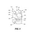
- FIG. 4illustrates a perspective view of an implantable device, according to still another exemplary disclosed embodiment.
- FIG. 5Aillustrates a perspective view of the implantable device of FIG. 4 with a locking cap, according to another exemplary disclosed embodiment.
- FIG. 5Bprovides a perspective view of the assembled device of FIG. 5A in situ.
- FIG. 5Cshows an enlarged view of the implanted device of FIG. 5B .
- FIG. 6Ashows a partially assembled view of the implantable device of FIG. 4 with a laminar hook, according to an exemplary disclosed embodiment.
- FIG. 6Bshows an exploded view of the device of FIG. 6A .
- FIG. 7Aprovides a perspective view of the assembled device of FIG. 6A in situ.
- FIG. 7Bshows an enlarged view of the implanted device of FIG. 7A .
- FIG. 8Aillustrates a perspective view of the implantable device of FIG. 4 with a laminar hook, according to another exemplary disclosed embodiment.
- FIG. 8Bshows an exploded view of the device of FIG. 8A .
- FIG. 9Aillustrates a perspective view of the implantable device of FIG. 4 with a laminar hook, according to yet another exemplary disclosed embodiment.
- FIG. 9Bshows an exploded view of the device of FIG. 9A .
- FIG. 10Aillustrates a rear perspective view of the assembled device of FIG. 8A in situ.
- FIG. 10Bshows an enlarged rear view of the implanted device of FIG. 1A .
- FIG. 10Cillustrates a front perspective view of the assembled device of FIG. 8A in situ.
- FIG. 10Dshows an enlarged front view of the implanted device of FIG. 10C .
- FIG. 11Aillustrates a perspective view of the assembled device of FIG. 9A in situ.
- FIG. 11Bshows an enlarged view of the implanted device of FIG. 11A .
- FIG. 12Aillustrates a perspective view of an implantable device, according to still another exemplary disclosed embodiment.
- FIG. 12Bprovides a perspective view of the assembled device of FIG. 12A in situ.
- FIG. 12Cshows an enlarged view of the implanted device of FIG. 12B .
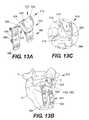
- FIG. 13Aillustrates a perspective view of an implantable device, according to yet still another exemplary disclosed embodiment.
- FIG. 13Bprovides a perspective view of the assembled device of FIG. 13A in situ.
- FIG. 13Cshows an enlarged view of the implanted device of FIG. 13B .
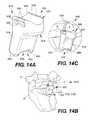
- FIG. 14Aillustrates a perspective view of an implantable device, according to even still another exemplary disclosed embodiment.
- FIG. 14Bprovides a perspective view of the assembled device of FIG. 14A in situ.
- FIG. 14Cshows an enlarged view of the implanted device of FIG. 14B .
- the implantable device 10can include a spacer or support body 12 that is configured to be implanted between the spinous process 2 of a lumbar vertebra 4 , such as the fifth lumbar (L5) spinous process, and an adjacent vertebra.
- An anchor member 14can be provided to secure the support body 12 to the adjacent vertebra, which can be, for example, the sacrum 8 .
- the device 10can help with alignment of the spinal column by maintaining the vertebra 4 and its spinous process 2 in the proper spatial relationship with respect to adjacent vertebrae, thereby reducing stress on the intervertebral disc.
- the body 12may include a first member 20 configured for placement beneath a spinous process 2 , which can serve as a scaffold or cradle to stabilize the spinous process 2 .
- the first member 20can include an upper surface 22 , a lower surface 24 , and a sidewall 26 extending in between.
- the upper surface 22can include a bone-contacting region 28 for placement of the spinous process 2 thereon.
- the bone-contacting region 28may comprise, for example, a contoured surface defining a saddle region.
- the bone-contacting region 28may further include surface features, such as for example, barbs, surface roughening or teeth 30 , as shown, to enhance its ability to grip the bony surface of the spinous process 2 .
- Surface featuresmay also include bioactive coatings, such as for example, porous coatings containing biologically active material that promotes bone tissue growth. These surface features may appear on any component of the implantable device 10 .
- Channels 32may be formed along the sidewall 26 and extend into openings 34 at the upper surface 22 , as shown in FIG. 1A .
- one channel 32may be formed on each lateral side of the first member 20 .
- a single channel 32may be provided that extends across the first member 20 and opens up at both of the lateral sides.
- the channels 32 and openings 34enable a flexible fixation element 50 , such as for example, a wire, ligament, band, fabric webbing, or suture formed of a metallic, polymeric, synthetic, or natural material, and composites thereof, to be passed through the first member 20 and tied around the spinous process 2 , thereby securing the bone to the device 10 as shown in FIGS. 1B and 1C .
- the first member 20may be attached to a second, base member 60 by a linking member 40 .
- the second member 60may include an upper surface 62 , lower surface 64 , and a sidewall 66 extending in between.
- the linking member 40may extend at one end from the lower surface 24 of the first member 20 to a second end on the upper surface 62 of the second, base member 60 .
- the linking member 40may be flexible (i.e., compressible and/or extendable) to provide the spinous process 2 with a certain limited degree of movement after the device 10 has been implanted.
- the linking member 40may take the form of a spring 42 , which would enable a vertebra 4 attached to the spinous process 2 to flex, rotate, and/or laterally bend in a controlled manner to accommodate patient movement.
- the second, base member 60may cooperate with an anchor member 14 for securing the implantable device 10 to the patient.
- the lower surface 64 of the second, base member 60may include a channel or groove 68 extending across the base member 60 .
- the anchor member 14may take the form of, for example, a detachable bone plate 80 having a rod-shaped attachment end 82 that is configured to be held within the groove 68 of the base member 60 .
- the groove 68having a C-shape, allows the bone plate 80 to be snap-fitted onto the base member 60 and still be rotatable, thereby providing an adjustable joint between the support body 12 and the anchor member 14 .
- a plastic liner formed from, for example, a polyethylene such as ultra high molecular weight polyethylene (UHMWPE) or polyetheretherketone (PEEK)can be provided between the rod-like attachment end 82 and the groove 68 , in order to provide smooth gliding motion of the body 12 against the plate 80 .
- UHMWPEultra high molecular weight polyethylene
- PEEKpolyetheretherketone
- the bone plate 80may further include one or more extensions or legs 84 extending from the rod-like attachment end 82 . As shown in FIG. 1B , two legs 84 may extend, one on each end, from the rod-like attachment end 82 . Alternatively, the bone plate 80 may be formed with more than two legs 84 , if desired.
- the legs 84may further include fastener holes 86 for the insertion of bone fasteners, such as for example, bone screws 88 , thereby enabling the secure attachment of the bone plate 80 to a bony surface such as the sacrum 8 . Although screws 88 have been described, it is understood that other alternative bone fasteners such as pins, tacks, and rivets may be used with the present invention.
- the legs 84are positioned so as to flank the median crest when attached to the sacrum.
- Surface featuressuch as, for example, a bioactive coating and/or teeth 30 may also be provided on the legs 84 to enhance attachment to the bony surface.
- the spacer body 12may be assembled to the anchor member 14 prior to implantation.
- the spacer body 12can be positioned such that the spinous process 2 of the vertebra 4 to be supported rests onto the bone-contacting region 28 , and the anchor member 14 is placed against the sacrum 8 . Thereafter, screws 88 can be inserted through the fastener holes 86 to secure the anchor member 14 to the sacrum 8 .
- a flexible fixation element 50can be tied around the spinous process 2 and the first member 20 of the spacer body 12 to secure the spinous process 2 to the spacer body 12 .
- a partially assembled device 10may be implanted.
- the anchor member 14may first be secured to the sacrum 8 with screws 88 .
- the spacer body 12may be snap-fitted to the anchor member 14 and manipulated such that the spinous process 2 of the vertebra 4 to be supported rests on the bone-contacting region 28 .
- a flexible fixation element 50can be used to secure the first member 20 of the spacer body 12 to the spinous process, as shown.
- FIGS. 2A-2Cillustrate an implantable device 110 similar to the device 10 of FIGS. 1A-1C , but with a flexible cushion 144 connecting the first member 120 to the second member 160 .
- the flexible cushion 144may comprise an elastomeric material.
- the flexible cushion 144may comprise a fabric cover that encloses an elastomeric material such as, for example, silicone or rubber, or a swellable material such as a hydrogel.
- the flexible cushion 144may be formed with pleats or crimps to facilitate compression and/or flexion, as shown in FIG. 2A .
- the flexible cushion 144can enable the vertebra 4 attached to the spinous process 2 to flex, rotate, and/or laterally bend in a controlled manner to accommodate patient movement.
- the degree of flexibility or resistancemay be controlled by selecting a material having a desired modulus of elasticity to form the linking members 40 , 140 , or by varying the thickness or dimensions of the linking members 40 , 140 to adjust the level of resistance.
- various other flexible and/or conformable designs, shapes, and sizesmay be utilized for the linking member 40 , 140 of the present disclosure.
- the spacer bodies 12 , 112 of the present inventionmay also be secured to the patient using a rod and bone anchor system 170 , as shown in FIGS. 3A and 3B .
- the use of a rod and bone anchor system 170enables the implantable devices 10 , 110 of the present invention to be adapted for insertion at any level of the spinal column.
- the rod-based systemsmay be used to secure a spacer body 12 , 112 between any pair of adjacent vertebrae by securing the anchors of the rod to the pedicles of the vertebra adjacent to the vertebra and its spinous process being stabilized.
- the rod and bone anchor system 170can include a rod 172 and at least one bone anchor 174 .
- the bone anchor 174can comprise, for example, a polyaxial screw.
- the devicemay be configured such that the rod 172 snaps into the channel 168 of the second, base member 160 , similar in respect to the rod-like attachment end 82 of the bone plate 80 .
- An exemplary embodiment of a bone anchor 174 suitable for use with the present inventionis shown in FIGS. 3A and 3B . As illustrated, the bone anchor 174 includes an elongated threaded body 176 extending into a head portion 178 .
- the head portion 178includes a hollow spherical cavity 190 for receiving a connecting element such as, for example, a spherical clamp ring (not shown) that fits over the rod 172 .
- a locking cap 192may be slidingly received by the head portion 178 and secured thereon with a threaded screw 194 .
- the locking cap 192may also include a spherical cavity 196 to cooperate with the spherical clamp ring such that screwing the cap 192 onto the head portion 178 secures the bone anchor 174 to the rod 172 .
- two anchors 174are shown in FIGS. 3A and 3B , a plurality of anchors 174 may be used with any given rod 172 , depending on the needs of the patient. It is also understood that a number of differently designed anchors may be used with the present invention in order to provide the surgeon with the ability to adapt to anatomical variations and secure the rod 172 to the patient in an effective manner.
- the implantable device 210can include a spacer or support body 212 , as shown in FIG. 4 .
- the body 212may be similar to the bodies 12 , 112 of devices 10 , 110 , with like elements of the device 210 having the same reference numerals as device 10 , following the prefix “2”.
- the body 212can include a first member 220 having raised sidewalls 226 that form wing-like projections 236 .
- the projections 236create a deeper saddle region 228 for seating the spinous process 2 therein, and further cradling the bone during use.
- Apertures or through-holes 238may be provided on the projections 236 for attachment of a fixation device.
- a flexible fixation element 50 , 150such as those previously described for use with devices 10 , 110 may also be applied in this embodiment to secure the spinous process 2 to the body 212 .
- FIGS. 5A-5Cillustrate the implantable device 210 in use with a locking cap 252 having a substantially U-shaped body formed by a pair of bent legs 256 .
- the locking cap 252can be shaped and sized as a bracket for engagement over the first member 220 .
- Elongate slots 258 located on the legs 256are configured to align with the through-holes 238 of the projections 236 to allow passage of a fixation element therethrough.
- FIG. 5A-5Cillustrate the implantable device 210 in use with a locking cap 252 having a substantially U-shaped body formed by a pair of bent legs 256 .
- the locking cap 252can be shaped and sized as a bracket for engagement over the first member 220 .
- Elongate slots 258 located on the legs 256are configured to align with the through-holes 238 of the projections 236 to allow passage of a fixation element therethrough.
- a bone fastener 200may be inserted through the slots 258 , securing together the locking cap 252 , support body 212 and spinous process 2 during use.
- the bone fastener 200can include a head 202 extending into an elongate threaded body 204 configured for insertion through bone tissue.
- a cap 206may be provided.
- the cap 206may include a hollow body cavity 208 for receiving the distal end of the threaded body 204 , as shown in FIG. 5A .
- a suitable bone fastener 200may be found in U.S. provisional No. 60/669,346 filed on Apr. 8, 2005, the contents of which are hereby incorporated in its entirety by reference.
- the fixation elementcan comprise a laminar hook 300 , which may be provided for use with the spacer or support body 212 of the present invention.
- the laminar hook 300can include a pair of legs 302 connected by a curved midsection 304 . Collectively, the legs 302 and midsection 304 form a curved or wavy M-shaped body, with the midsection 304 including a U-shaped protrusion or notch, as illustrated.
- the legs 302cooperate with rotating arms 310 situated on either side of the spacer body 212 to allow pivoting movement of the hook 300 with respect to the spacer body 212 .
- the rotating arms 310can have a generally cylindrical shape, with one closed end 312 and an opposite, open end 314 including an opening 316 extending generally parallel to the longitudinal axis of the arm 310 .
- the closed end 312can have a smooth, curved edge while the open end 314 can have a flat edge so as to enable flush placement against the spacer body 212 .
- a locking cap 324can be inserted through one of the apertures 238 on the spacer body 212 .
- the locking cap 324can include a head portion 326 and a stem portion 328 , and a through-hole 330 for insertion of a pin 322 therethrough.
- the stem portion 328should be sized and configured for insertion through the aperture 238 of the spacer body 212 and still be freely rotatable.
- An arm 310is then placed against the stem portion 328 , with the stem portion 328 fitting within the opening 316 of the arm 310 such that the spacer body 212 is sandwiched in between.
- a pin 322can be placed through a through-hole 320 on the arm 310 , the through-hole 320 being configured to align with the through-hole 330 of the cap 324 . Accordingly, the pin maintains the arm 310 and cap 324 against the spacer body 212 while allowing free rotational movement of the arm 310 and cap 324 with respect to the body 212 .
- the free ends 306 of the hook 300can be inserted through openings 318 extending through the arms 310 , the openings 318 being generally perpendicular to the longitudinal axis of the arms 310 .
- the legs 302 of the hook 300can include threaded portions 308 near the free ends 306 that extend beyond the arms 310 when assembled.
- a fastener 334such as for example, a threaded nut can be provided to secure the legs 302 to the arms 310 .
- the opening 318can extend into a widened cavity 336 that would allow the fastener 334 , once secured to the legs 302 , to reside therein, as shown in FIG. 6A .
- any suitable alternative connectioncan be provided for securing the fastener 334 to the legs 302 .
- the legs 302can be provided with notches or grooves, while the fastener 334 can include corresponding teeth or ridges for ratcheting over the legs 302 .
- it is desirable to provide a mechanism for securing the hook 300 to the rotatable arms 310which would allow the surgeon the flexibility to adjust the length of the hook 300 relative to the spacer body 212 , in order to accommodate different patient anatomies.
- the laminar hook 300can assist with the positioning and attachment of the implantable device 210 to the vertebra 4 .
- the implantable device 210can be implanted between a vertebra 4 and an adjacent vertebra, such as for example, the sacrum 8 .
- the device 210may be attached using, for example, the bone plate 80 previously described, or a rod and screw system 170 as shown. Further, it is understood that the device 210 may be inserted between any adjacent pair of vertebrae.
- the laminar hook 300can be clasped against the lamina, with the midsection 304 having the U-shaped protrusion or notch extending around the lamina.
- the hook 300should be sufficiently angled or curved so as to conform to the natural anatomical curves of the lamina, as shown in greater detail in FIG. 7B .
- the laminar hook 300can be fully assembled after the implantable device 210 has been implanted between a pair of vertebrae.
- the legs 302can be secured to the arms 310 with the fasteners 334 after the hook 300 has been properly positioned around the lamina.
- the surgeoncan adjust the length of the hook 300 by manipulating the fastener 334 with respect to the rotatable arms 310 in order to adapt to variations in the patient's anatomy.
- a laminar hook 340which can include a pivotable head portion 350 .
- the head portion 350has a first end 352 from which a hook or tab 356 for grasping around the lamina can extend, as shown in FIG. 8A .
- the opposed, second end 354 of the head portion 350can include slots 358 which extend into openings 360 along the sides of the head portion 350 , as illustrated in FIG. 8B .
- legs 342can be provided having threaded portions 348 near the first and second, opposed ends 344 , 346 .
- the first ends 344 of the legs 342can be inserted into the slots 358 of the head portion 350 , while the second, opposed ends 346 of the legs 342 can extend into rotatable arms 310 , where the legs 342 can be secured to the arms 310 using fasteners 334 , similar to the mechanism previously described for the laminar hook 300 of FIGS. 6A and 6B .
- the laminar hook 340 of FIGS. 8A and 8Bcan be similar to laminar hook 300 in all respects to the manner in which the arms 310 connect to the spacer body 212 .
- a cylindrically-shaped bushing 362can be provided.
- the bushing 362can be configured to reside within the cylindrically shaped opening 360 along the sides of the head portion 350 , and can be sized and shaped so as to allow free rotational movement within the opening 360 .
- the bushing 362can include a threaded hole 364 for attachment to the threaded portions 348 of the first ends 344 of the legs 342 .
- a threaded connectionis shown and described, it is contemplated that any suitable alternative connection can be provided for securing the fastener 334 and bushing 362 to the legs 342 .
- the legs 342can be provided with notches or grooves, while the fastener 334 and bushing 362 can include corresponding teeth or ridges for ratcheting over the legs 342 .
- the bushings 362can be placed into the openings 360 of the head portion 350 . Thereafter, the legs 342 can be inserted into the slots 358 , and secured to the bushings 362 by screwing the threaded portions 348 near the first ends 344 into the threaded holes 364 of the bushings 362 . The free, second ends 346 of the legs 342 can then be inserted into the attached rotatable arms 310 along the sides of the spacer body 212 , and secured therein with fasteners 334 , such as for example, threaded nuts.
- fasteners 334such as for example, threaded nuts.
- the fully-assembled laminar hook 340 of the present embodimentcan assist with the positioning and attachment of the implantable device 210 to the vertebra 4 .
- the implantable device 210can be implanted between a vertebra 4 and an adjacent vertebra, such as for example, the sacrum 8 .
- the device 210may be inserted between any adjacent pair of vertebrae using, for example, a rod and screw system 170 as shown.
- the laminar hook 340can be clasped onto the lamina, with the hook or tab 356 extending around the lamina, as shown in greater detail in FIG. 10B .
- the hook 340can accommodate variations in patient anatomy.
- the legs 342can be angled or curved so as to better conform to the natural anatomical curves of the lamina, as shown in greater detail in FIG. 10D .
- the implantable device 210can be implanted with the laminar hook 340 fully attached to the spacer body 212 as previously described.
- the laminar hook 340can be fully attached to the spacer body 212 after the implantable device 210 has been inserted between a pair of vertebrae.
- the laminar hook 340can be partially assembled (i.e., the legs 342 are connected to the head portion 350 ) when the implantable device 210 (including the rotatable arms 310 ) is implanted.
- the legs 342can be secured to the arms 310 with the fasteners 334 once the hook 340 has been properly positioned around the lamina.
- the surgeoncan adjust the length of the hook 340 by manipulating the fastener 334 with respect to the rotatable arms 310 and legs 342 in order to adapt to variations in the patient's anatomy.
- the hook 370can include a pair of legs 372 and a bridge portion 386 pivotably connected to the legs 372 by a hinge joint 384 , as shown in FIG. 9A .
- Each of the legs 372can include a first end 374 having a screw opening 380 and a second, opposed end 376 including a threaded portion 378 for insertion into a rotatable arm 310 , where the leg 372 can be secured to the arm 310 using a fastener 334 , similar to the mechanism previously described for laminar hooks 300 , 340 .
- the laminar hook 370 of FIGS. 9A and 9Bcan be similar to laminar hooks 300 , 340 in all respects to the manner in which the arms 310 connect to the spacer body 212 .
- the bridge portion 386can have a substantially U shape, with the free ends 388 terminating at screw openings 390 .
- the midsection 392 of the bridge portion 386can include a tab 394 extending at an angle therefrom, as illustrated in FIG. 9A .
- the tab 394can take any shape and size suitable for gripping or grabbing around the lamina, such as a solid plate as shown. However, it is contemplated that the tab 394 can also be a U-shaped body. Further, the tab 394 can be formed integral to the bridge portion 386 or as a separate component. If desired, the tab 394 may be configured to be angularly adjustable and fixable in a desired angle relative to the bridge portion 386 during implantation for greater flexibility.
- the bridge portion 386can be attached to legs 372 by inserting a fastener 382 , such as for example, a screw, through openings 380 of the legs and openings 390 of the bridge portion 386 . Thereafter, the legs 372 can be inserted into the attached rotatable arms 310 along the sides of the spacer body 212 , and secured therein with fasteners 334 , such as for example, threaded nuts.
- a fastener 382such as for example, a screw
- the fully assembled laminar hook 370 of the present embodimentcan assist with the positioning and attachment of the implantable device 210 to the vertebra 4 .
- the implantable device 210can be implanted between a vertebra 4 and an adjacent vertebra, such as for example, the sacrum 8 . It is understood, of course, that the device 210 may be inserted between any adjacent pair of vertebrae using, for example, a rod and screw system 170 as shown.
- the laminar hook 370can be clasped onto the lamina with the tab 394 extending around the lamina, as shown in greater detail in FIG. 11B .
- the hook 370can accommodate variations in patient anatomy.
- the legs 372can be angled or curved so as to better conform to the natural anatomical curves of the lamina, similar to the legs 342 of laminar hook 340 .
- the implantable device 210can be implanted with the laminar hook 370 fully attached to the spacer body 212 as described in the methods above.
- the laminar hook 370can be fully attached to the spacer body 212 after the implantable device 210 has been inserted between a pair of vertebrae.
- the laminar hook 370can be partially assembled (i.e., the legs 372 are connected to the bridge portion 386 ) when the implantable device 210 (including the rotatable arms 310 ) is implanted.
- the legs 372can be secured to the arms 310 with the fasteners 334 once the tab 394 has been properly positioned around the lamina.
- the surgeoncan adjust the height of the hook 370 by manipulating the fastener 334 with respect to the rotatable arms 310 and legs 372 in order to adapt to variations in the patient's anatomy.
- the laminar hooks 300 , 340 , 370 of the present inventioncan be formed from a variety of suitable biocompatible materials, either alone or in combination with one another.
- suitable materials for forming all or part of the hooks 300 , 340 , 370include metals, such as for example, stainless steel, titanium, and their alloys, as well as polymers, such as for example, polyetheretherketone (PEEK).
- PEEKpolyetheretherketone
- an implantable device 410 in accordance with one exemplary embodiment of the present disclosureincludes a support bracket 412 having similar features to those of implantable device 10 . Where applicable, like elements of the device 410 are designated with the same reference numerals as device 10 following the prefix “4”.
- the support bracket 412can include a bone scaffold portion 420 configured for placement beneath a spinous process 2 .
- the scaffold portion 420can extend into a neck region 416 , which can extend into an anchor portion configured as, for example, a bone plate 480 for attachment to an adjacent vertebra. As shown, the scaffold portion 420 can extend at about a 90° angle with respect to the bone plate 480 . However, it is understood that the scaffold portion 420 may extend at various angles with respect to the anchor portion in keeping with the spirit of the disclosure.
- the scaffold portion 420can include an upper surface 422 , a lower surface 424 , and a sidewall 426 extending in between.
- the upper surface 422can include a contoured area defining a saddle region 428 for placement of the spinous process 2 thereon.
- Channels 432may be formed along the sidewall 426 and extend into openings 434 at the upper surface 422 , as shown in FIG. 12A .
- one channel 432may be formed on each lateral side of the scaffold portion 420 .
- a single channel 432may be provided which extends across the scaffold portion 420 and opens at both lateral sides.
- a flexible fixation element 450such as, for example, a wire, ligament, band, fabric webbing, or suture formed of a metallic, polymeric, synthetic, or natural material, and composites thereof may be passed through the scaffold portion 420 and tied around the spinous process 2 , thereby securing the bone to the device 410 as shown in FIGS. 12B and 12C .
- the scaffold portion 420can extend into a bone plate 480 , which may include one or more extensions or legs 484 . As shown in FIG. 12B , two legs 484 may be provided. Of course, the bone plate 480 may be formed with more than two legs 484 if desired.
- the legs 484may further include fastener holes 486 for insertion of fasteners, such as for example, bone screws 488 , thereby enabling the secure attachment of the bone plate 480 to a bony surface such as the sacrum 8 .
- the legs 484are positioned so as to flank the median crest when the plate 480 is attached to the sacrum 8 . Surface features such as, for example, a bioactive coating and/or teeth 430 may also be provided on the legs 484 for enhancing attachment to the bony surface.
- an implantable device 510 including a unitary support body or bracket 512is shown.
- the implantable device 510shares similar features to those of implantable device 10 . Where applicable, like elements of the device 510 are designated with the same reference numerals as device 10 , following the prefix “5”.
- the support bracket 512includes a bone carrier portion 520 which extends into a bone plate 580 .
- the bone carrier portion 520can include raised sidewalls 526 that form wing-like projections 536 .
- the projections 536create a deeper saddle region 228 for seating the spinous process 2 therein, and further cradling or supporting the bone during use.
- Apertures or through-holes 538may be provided on the projections 536 for attachment of a fixation device.
- a flexible fixation elementsuch as those previously described for use with devices 10 , 110 may also be applied in this embodiment to secure the spinous process 2 to the carrier portion 520 .
- a rigid fixation elementsuch as a locking cap and bone fastener (not shown) similar to those provided with implantable device 210 may also be utilized to firmly secure the bone to the support bracket 512 .
- a laminar hook 300 , 340 , 370 similar to the ones previously describedmay also be implemented with the support bracket 512 of the present embodiment.
- the carrier portion 520can extend into an anchor portion configured as, for example, a bone plate 580 which may include one or more extensions or legs 584 .
- a bone plate 580which may include one or more extensions or legs 584 .
- two legs 584may be provided.
- the bone plate 580may be formed with more than two legs 584 if desired.
- the legs 584may further include fastener holes 586 for insertion of fasteners, such as for example, bone screws 588 , thereby enabling the secure attachment of the bone plate 580 to a bony surface such as the sacrum 8 .
- the legs 584are positioned so as to flank the median crest when the plate 580 is attached to the sacrum. Surface features such as, for example, a bioactive coating and/or teeth 530 may also be provided on the legs 584 for enhancing attachment to the bony surface.
- FIGS. 14A-14Cillustrate yet still another exemplary embodiment of the present disclosure.
- an implantable device 610includes a unitary support bracket 612 that comprises a body 616 having a scaffold portion 620 at one end and an anchor portion 680 at an opposite end.
- the implantable device 610shares similar features to those of implantable device 10 . Where applicable, like elements of the device 610 are designated with the same reference numerals as device 10 , following the prefix “6”.
- the scaffold portion 620may be configured in a similar manner to the scaffold portion 420 of implantable device 410 shown in FIGS. 12A-12C for supporting a spinous process 2 . However, in the illustrated embodiment, the scaffold portion 620 extends into a body 616 that terminates at an anchor portion 680 .
- the anchor portion 680may comprise a pair of legs 684 defining a bone-gripping portion 648 therebetween.
- the support bracket 612may be positioned such that the spinous process 2 rests on the saddle region 628 of the scaffold portion 620 and a flexible fixation element 650 secures the bone to the scaffold portion 620 .
- the anchor portion 680can be positioned to rest against a bony surface of the adjacent vertebra, such as the median crest, where the adjacent vertebra is the sacrum 8 .
- the implantable device 610can be modified in size (i.e., height and width) and shape to be used at any level of the spinal column.
- the support bodies or brackets 412 , 512 , 612 of the present disclosuremay be provided as rigid fixation devices or as semi-rigid, flexible fixation devices, depending on the materials selected for their construction and the particular needs of the patient. That is, a rigid fixation device may be provided by constructing the brackets from a biocompatible metal, such as for example, titanium or stainless steel, or a rigid polymer, such as for example, polyetheretherketone (PEEK). However, a semi-rigid fixation device having limited flexibility (i.e., compression and/or extension) may be provided by constructing the brackets from a polymer material, such as for example, silicone, a rubber-like material, or a polyethylene such as ultra high molecular weight polyethylene (UHMWPE).
- a polymer materialsuch as for example, silicone, a rubber-like material, or a polyethylene such as ultra high molecular weight polyethylene (UHMWPE).
- the devicesmay be constructed from a combination of materials to provide a semi-flexible, semi-rigid fixation device.
- the brackets 412 , 512may be constructed of mostly metal but for a neck region 416 , 516 comprising a polymeric material to enable some compression and/or extension under normal compression loads.
- the specific materials included in each portion of the implantable devicemay be selected based on a desired degree of flexibility and/or compressibility, or to provide biocompatibility and/or bioactive characteristics.
- a number of biocompatible materialsare suitable for forming the devices of the present disclosure.
- the devicemay be formed from a medical grade metal such as pure titanium or a titanium alloy such as titanium-vanadium-aluminum alloy.
- the devicemay also be formed from, e.g., stainless steel or cobalt chrome. It is also possible to form the device from a shape-memory material such as nickel titanium or nitinol.
- Other suitable biocompatible materialsinclude ceramic materials.
- the ceramic materialmay be a mixture of particles, for example, a mixture of a metal or metals and/or a ceramic non-metallic material or materials.
- the implantable device of the present inventioncan also be formed from a suitable biocompatible polymeric material.
- suitable synthetic polymersinclude, but are not limited to, polyvinyl alcohol (PVA) and alkylated or acylated derivatives thereof, polyethylene (PE), polyurethane (PU), polypropylene (PP), nylon, polycaprolactone (PCL), and copolymers and combinations thereof.
- suitable synthetic non-biodegradable polymersinclude, but are not limited to, various polyacrylates, ethylene-vinyl acetates (and other acyl-substituted cellulose acetates), polystyrenes, polyvinyl oxides, polyvinyl fluorides, poly(vinyl imidazoles), chlorosulphonated polyolefins, polyethylene oxides, polytetrafluoroethylenes and nylons.
- Another polymeric materialwhich is particularly suitable for use in production of mouldable compositions, is a hydrolysed polymer or copolymer of a vinyl ester, particularly a hydrolysed polymer or copolymer of vinyl acetate.
- Other preferred polymeric materialsinclude ultra-high molecular-weight polyethylene (UHMWPE) and polyetheretherketone (PEEK).
- the flexible portions of the present devicecan be formed of a suitable elastomeric material, such as for example, silicone, and natural or synthetic rubber or rubber-like materials.
- the flexible linking member 40can be formed of any of the biocompatible metals previously discussed.
- the cushion 140it is possible to construct the cushion 140 from an elastomeric or viscoelastic material contained within a retaining cover or jacket formed of, for example, a fabric.
- a wide variety of fiber materialsare suitable for forming the fabric cover, such as for example, polyester, polyethylene, and other high tenacity polymeric fabrics, as well as carbon fiber yarns, ceramic fibers, metallic fibers, including mixtures of one or more of these materials and including fibers made therefrom.
- the textile fabricmay be formed using weaving, knitting, braiding or embroidery. The fabric may be produced in the desired profile or may be reduced to the desired profile from a larger amount of fabric, for instance, by cutting or pressing.
- the elastomeric or viscoelastic core material within the fabric covermay comprise any of the suitable materials previously mentioned.
- the coremay also comprise a swellable plastic such as a polymeric composite or hydrogel, such as polyvinylalcohol, polyvinyl pyrrolidone or derivatives of polyacrylic or polymethacrylic acid.
- suitable polymersare polyurethanes, polyureas, PAN, polydimethylsiloxanes (silicone rubber), and highly crystalline multiblock acrylic and methacrylic copolymers.
- hydrophilic polymersexamples include high-molecular weight polyacrylamide, polyacrylic acid, polyvinylpyrrolidone, polyethyleneoxide, copolymers of ethyleneoxide and propyleneoxide or hyaluronic acid; covalently crosslinked hydrogels such as hydrophilic esters or amides of polyacrylic or polymethacrylic acids; and physically crosslinked hydrogels, such as hydrolyzates or arninolyzates of PAN.
- Hydrogels useful for forming the elastomeric material of the flexible cushion 140include lightly cross-linked biocompatible homopolymers and copolymers of hydrophilic monomers such as 2-hydroxylalkyl acrylates and methacrylates, e.g., 2-hydroxyethyl methacrylate (HEMA); N-vinyl monomers, for example, N-vinyl-2-pyrrolidone (N-VP); ethylenically unsaturated acids, for example, methacrylic acid (MA) and ethylenically unsaturated bases such as 2-(diethylamino)ethyl methacrylate (DEAEMA).
- hydrophilic monomerssuch as 2-hydroxylalkyl acrylates and methacrylates, e.g., 2-hydroxyethyl methacrylate (HEMA); N-vinyl monomers, for example, N-vinyl-2-pyrrolidone (N-VP); ethylenically unsaturated acids, for example, methacryl
- the copolymersmay further include residues from non-hydrophilic monomers such as alkyl methacrylates, for example, methyl methacrylate (MMA), and the like.
- non-hydrophilic monomerssuch as alkyl methacrylates, for example, methyl methacrylate (MMA), and the like.
- MMAmethyl methacrylate
- Another type of suitable hydrogelincludes HYPANTM and poly(vinyl alcohol) (PVA) hydrogels.
- the devicemay include a number of surface modifications.
- sections of the implantable devicemay include surface alterations that may facilitate tissue attachment, bonding or fixation. These alterations may include surface teeth, barbs, beads, surface roughening, or the addition of bioactive coatings to one or more sections of the device.
- the devicemay also include roughened or porous surfaces. The roughened or porous surfaces may enhance attachment between implant surfaces and bone tissue. In addition, some porous surfaces may facilitate tissue ingrowth to form a biological bond between sections of the device and the surrounding bone and/or soft tissue.
- Roughened or porous surfacesmay be included on any portion of the device, and in particular, may be desirable for the portions of the device in direct contact with bony tissue such as the upper surfaces 22 of the support bodies 12 or the saddle regions 228 of the support bodies 212 which may benefit from bone tissue ingrowth.
- the surface of the devicemay also include biologically active agents. These agents may include osteogenic factors to further facilitate bonding between components of the device and the surrounding bone and/or soft tissue. Further, the device may include therapeutic agents such as antibiotics, steroids, anti-thrombotic agents, anti-inflammatory drugs, and/or analgesic agents. In one embodiment, the biologically active agent may be contained in a coating on the device. Alternatively, or in addition, the device may be porous and the biologically active agent may be contained in the pores of the device.
- the biologically active agentmay be, for example, bone morphogenic protein (BMP) for inducing cartilage or bone growth.
- BMPbone morphogenic protein
- the surgeonmay use the devices of the present disclosure to treat a number of clinical problems.
- the devicesmay be used to treat degenerative disc disease and/or disc herniation.
- the devicesmay also be used to treat spinal stenosis, including central and/or lateral canal stenosis.
- the devicesmay be used before, after, or in conjunction with other treatments or implants, including adjacent rigid fixation, adjacent spinal decompression, fusion, and/or facet replacement or repair.
- the devices of the present disclosuremay be surgically implanted in a variety of ways without impairing the effectiveness of the devices. For example, the surgeon may select a number of different operative approaches and/or incision positions and/or sizes. Further, the surgeon may implant each of the components of the devices in various sequences. The specific operative procedures may be selected based on patient-specific clinical factors.
- a number of different incisions and/or operative proceduresmay be used to implant the devices of the present disclosure.
- the surgeonmay use a mid-line incision over the lumbar and sacral vertebrae to expose the L5-S1 interspinous region.
- the surgeonmay use one or more incisions positioned lateral to the spine.
- the surgeonmay use a minimally-invasive procedure including various scopes, cannula, and/or robotic implantation devices to deliver the devices to the surgical site.
- the devices 10 of the present disclosuremay provide an improved system and method for treating various disorders of the spine.
- the devicesprovide a mechanism for treating disorders of the spine at the L5-S1 vertebral level.
- the devices of the present disclosuremay also be useful for treating diseases of the spine at other vertebral levels.
- the devices of the present inventionmay also be used to stabilize lumbar vertebrae above the L5 level. For example, in the case of an L5 laminectomy, it is possible to use the present device to stabilize the L4 vertebra while placing the screws of the rod-based device system into the pedicles of the adjacent L5 vertebra, thereby providing a supporting bridge between the L4-L5 region.
- the devices provided in this disclosuremay be used to stabilize any pair of adjacent vertebrae by securing the anchors of the rod to the pedicles of the adjacent vertebra to the spinous process being supported.
- the methods and devices of the present disclosuremay be significantly less invasive and/or produce less drastic and more reversible anatomic changes as compared to other procedures including spinal fusion and total disc replacement.
- the device of the present disclosuremay limit normal spinal motion but provide some controlled movement in flexion, extension, rotation, and/or lateral bending. Further, the devices and methods of the present disclosure may be particularly well-suited for treating various stages of degenerative disc and/or spinal stenosis, particularly at the L5-S1 level.
Landscapes
- Health & Medical Sciences (AREA)
- Orthopedic Medicine & Surgery (AREA)
- Neurology (AREA)
- Life Sciences & Earth Sciences (AREA)
- Engineering & Computer Science (AREA)
- Biomedical Technology (AREA)
- Surgery (AREA)
- Veterinary Medicine (AREA)
- Animal Behavior & Ethology (AREA)
- Heart & Thoracic Surgery (AREA)
- Public Health (AREA)
- General Health & Medical Sciences (AREA)
- Molecular Biology (AREA)
- Nuclear Medicine, Radiotherapy & Molecular Imaging (AREA)
- Medical Informatics (AREA)
- Cardiology (AREA)
- Oral & Maxillofacial Surgery (AREA)
- Transplantation (AREA)
- Vascular Medicine (AREA)
- Neurosurgery (AREA)
- Prostheses (AREA)
- Surgical Instruments (AREA)
- Materials For Medical Uses (AREA)
Abstract
Description
Claims (18)
Priority Applications (3)
| Application Number | Priority Date | Filing Date | Title |
|---|---|---|---|
| US11/535,210US8328848B2 (en) | 2005-09-27 | 2006-09-26 | Interspinous vertebral stabilization devices |
| US13/709,449US9173746B2 (en) | 2005-09-27 | 2012-12-10 | Interspinous vertebral stabilization devices |
| US14/927,421US10363071B2 (en) | 2005-09-27 | 2015-10-29 | Interspinous vertebral stabilization devices |
Applications Claiming Priority (2)
| Application Number | Priority Date | Filing Date | Title |
|---|---|---|---|
| US72080905P | 2005-09-27 | 2005-09-27 | |
| US11/535,210US8328848B2 (en) | 2005-09-27 | 2006-09-26 | Interspinous vertebral stabilization devices |
Related Child Applications (1)
| Application Number | Title | Priority Date | Filing Date |
|---|---|---|---|
| US13/709,449ContinuationUS9173746B2 (en) | 2005-09-27 | 2012-12-10 | Interspinous vertebral stabilization devices |
Publications (2)
| Publication Number | Publication Date |
|---|---|
| US20070161993A1 US20070161993A1 (en) | 2007-07-12 |
| US8328848B2true US8328848B2 (en) | 2012-12-11 |
Family
ID=37668164
Family Applications (3)
| Application Number | Title | Priority Date | Filing Date |
|---|---|---|---|
| US11/535,210Expired - Fee RelatedUS8328848B2 (en) | 2005-09-27 | 2006-09-26 | Interspinous vertebral stabilization devices |
| US13/709,449Active2026-10-26US9173746B2 (en) | 2005-09-27 | 2012-12-10 | Interspinous vertebral stabilization devices |
| US14/927,421Active2027-01-09US10363071B2 (en) | 2005-09-27 | 2015-10-29 | Interspinous vertebral stabilization devices |
Family Applications After (2)
| Application Number | Title | Priority Date | Filing Date |
|---|---|---|---|
| US13/709,449Active2026-10-26US9173746B2 (en) | 2005-09-27 | 2012-12-10 | Interspinous vertebral stabilization devices |
| US14/927,421Active2027-01-09US10363071B2 (en) | 2005-09-27 | 2015-10-29 | Interspinous vertebral stabilization devices |
Country Status (14)
| Country | Link |
|---|---|
| US (3) | US8328848B2 (en) |
| EP (2) | EP1942817B1 (en) |
| JP (1) | JP5047176B2 (en) |
| KR (1) | KR101332384B1 (en) |
| CN (2) | CN103169533B (en) |
| AR (1) | AR057832A1 (en) |
| AU (1) | AU2006294772B2 (en) |
| CA (1) | CA2623883C (en) |
| ES (2) | ES2465568T3 (en) |
| IL (1) | IL190417A0 (en) |
| MX (1) | MX344497B (en) |
| TW (1) | TWI423782B (en) |
| WO (1) | WO2007038475A2 (en) |
| ZA (1) | ZA200802860B (en) |
Cited By (22)
| Publication number | Priority date | Publication date | Assignee | Title |
|---|---|---|---|---|
| US20120004727A1 (en)* | 2007-05-22 | 2012-01-05 | Eden Spine, Llc | Method Of Implanting An Interspinous Vertebral Implant |
| US20140155939A1 (en)* | 2011-06-20 | 2014-06-05 | Akita University | Spine immobilization tool |
| US8864828B2 (en) | 2004-10-20 | 2014-10-21 | Vertiflex, Inc. | Interspinous spacer |
| US8900271B2 (en) | 2004-10-20 | 2014-12-02 | The Board Of Trustees Of The Leland Stanford Junior University | Systems and methods for posterior dynamic stabilization of the spine |
| US9039742B2 (en) | 2004-10-20 | 2015-05-26 | The Board Of Trustees Of The Leland Stanford Junior University | Systems and methods for posterior dynamic stabilization of the spine |
| US20150182263A1 (en)* | 2013-03-15 | 2015-07-02 | Jcbd, Llc | Spinal stabilization system |
| US9119680B2 (en) | 2004-10-20 | 2015-09-01 | Vertiflex, Inc. | Interspinous spacer |
| US9155570B2 (en) | 2004-10-20 | 2015-10-13 | Vertiflex, Inc. | Interspinous spacer |
| US9918849B2 (en) | 2015-04-29 | 2018-03-20 | Institute for Musculoskeletal Science and Education, Ltd. | Coiled implants and systems and methods of use thereof |
| US10034693B2 (en) | 2016-07-07 | 2018-07-31 | Mark S. Stern | Spinous laminar clamp assembly |
| US10213317B2 (en) | 2017-03-13 | 2019-02-26 | Institute for Musculoskeletal Science and Education | Implant with supported helical members |
| WO2019070964A2 (en) | 2017-10-06 | 2019-04-11 | Mullin Brad | Spinal implant |
| US10357377B2 (en) | 2017-03-13 | 2019-07-23 | Institute for Musculoskeletal Science and Education, Ltd. | Implant with bone contacting elements having helical and undulating planar geometries |
| US10449051B2 (en) | 2015-04-29 | 2019-10-22 | Institute for Musculoskeletal Science and Education, Ltd. | Implant with curved bone contacting elements |
| US10478312B2 (en) | 2016-10-25 | 2019-11-19 | Institute for Musculoskeletal Science and Education, Ltd. | Implant with protected fusion zones |
| US10492921B2 (en) | 2015-04-29 | 2019-12-03 | Institute for Musculoskeletal Science and Education, Ltd. | Implant with arched bone contacting elements |
| US10512549B2 (en) | 2017-03-13 | 2019-12-24 | Institute for Musculoskeletal Science and Education, Ltd. | Implant with structural members arranged around a ring |
| US10667924B2 (en) | 2017-03-13 | 2020-06-02 | Institute for Musculoskeletal Science and Education, Ltd. | Corpectomy implant |
| US10695192B2 (en) | 2018-01-31 | 2020-06-30 | Institute for Musculoskeletal Science and Education, Ltd. | Implant with internal support members |
| US10709570B2 (en) | 2015-04-29 | 2020-07-14 | Institute for Musculoskeletal Science and Education, Ltd. | Implant with a diagonal insertion axis |
| US11504173B2 (en)* | 2020-09-16 | 2022-11-22 | Acumed Llc | Bone-stabilizing device having a pivotable buttress member |
| US20230240726A1 (en)* | 2022-01-28 | 2023-08-03 | Linares Spinal Devices, Llc | Expandable spring stepped in jack for installation between upper and lower succeeding articular processes |
Families Citing this family (123)
| Publication number | Priority date | Publication date | Assignee | Title |
|---|---|---|---|---|
| FR2812185B1 (en) | 2000-07-25 | 2003-02-28 | Spine Next Sa | SEMI-RIGID CONNECTION PIECE FOR RACHIS STABILIZATION |
| GB0107708D0 (en) | 2001-03-28 | 2001-05-16 | Imp College Innovations Ltd | Bone fixated,articulated joint load control device |
| US8114158B2 (en) | 2004-08-03 | 2012-02-14 | Kspine, Inc. | Facet device and method |
| US9161783B2 (en) | 2004-10-20 | 2015-10-20 | Vertiflex, Inc. | Interspinous spacer |
| US8425559B2 (en) | 2004-10-20 | 2013-04-23 | Vertiflex, Inc. | Systems and methods for posterior dynamic stabilization of the spine |
| US8945183B2 (en) | 2004-10-20 | 2015-02-03 | Vertiflex, Inc. | Interspinous process spacer instrument system with deployment indicator |
| US8128662B2 (en) | 2004-10-20 | 2012-03-06 | Vertiflex, Inc. | Minimally invasive tooling for delivery of interspinous spacer |
| US8123807B2 (en) | 2004-10-20 | 2012-02-28 | Vertiflex, Inc. | Systems and methods for posterior dynamic stabilization of the spine |
| US9023084B2 (en) | 2004-10-20 | 2015-05-05 | The Board Of Trustees Of The Leland Stanford Junior University | Systems and methods for stabilizing the motion or adjusting the position of the spine |
| US7763074B2 (en) | 2004-10-20 | 2010-07-27 | The Board Of Trustees Of The Leland Stanford Junior University | Systems and methods for posterior dynamic stabilization of the spine |
| US8409282B2 (en) | 2004-10-20 | 2013-04-02 | Vertiflex, Inc. | Systems and methods for posterior dynamic stabilization of the spine |
| US8012207B2 (en) | 2004-10-20 | 2011-09-06 | Vertiflex, Inc. | Systems and methods for posterior dynamic stabilization of the spine |
| US8317864B2 (en) | 2004-10-20 | 2012-11-27 | The Board Of Trustees Of The Leland Stanford Junior University | Systems and methods for posterior dynamic stabilization of the spine |
| US8277488B2 (en) | 2004-10-20 | 2012-10-02 | Vertiflex, Inc. | Interspinous spacer |
| US8613747B2 (en) | 2004-10-20 | 2013-12-24 | Vertiflex, Inc. | Spacer insertion instrument |
| US8123782B2 (en) | 2004-10-20 | 2012-02-28 | Vertiflex, Inc. | Interspinous spacer |
| US8241330B2 (en) | 2007-01-11 | 2012-08-14 | Lanx, Inc. | Spinous process implants and associated methods |
| US9055981B2 (en) | 2004-10-25 | 2015-06-16 | Lanx, Inc. | Spinal implants and methods |
| WO2006058221A2 (en) | 2004-11-24 | 2006-06-01 | Abdou Samy M | Devices and methods for inter-vertebral orthopedic device placement |
| EP2219538B1 (en) | 2004-12-06 | 2022-07-06 | Vertiflex, Inc. | Spacer insertion instrument |
| US8845726B2 (en) | 2006-10-18 | 2014-09-30 | Vertiflex, Inc. | Dilator |
| US7850732B2 (en)* | 2006-12-11 | 2010-12-14 | Warsaw Orthopedic, Inc. | Sacral prosthesis and surgical method |
| US9247968B2 (en) | 2007-01-11 | 2016-02-02 | Lanx, Inc. | Spinous process implants and associated methods |
| US9265532B2 (en) | 2007-01-11 | 2016-02-23 | Lanx, Inc. | Interspinous implants and methods |
| US7842074B2 (en) | 2007-02-26 | 2010-11-30 | Abdou M Samy | Spinal stabilization systems and methods of use |
| AU2008241447B2 (en) | 2007-04-16 | 2014-03-27 | Vertiflex, Inc. | Interspinous spacer |
| US20080269897A1 (en)* | 2007-04-26 | 2008-10-30 | Abhijeet Joshi | Implantable device and methods for repairing articulating joints for using the same |
| US20080268056A1 (en)* | 2007-04-26 | 2008-10-30 | Abhijeet Joshi | Injectable copolymer hydrogel useful for repairing vertebral compression fractures |
| US8409281B2 (en)* | 2007-05-01 | 2013-04-02 | Moximed, Inc. | Adjustable absorber designs for implantable device |
| US8123805B2 (en) | 2007-05-01 | 2012-02-28 | Moximed, Inc. | Adjustable absorber designs for implantable device |
| US8709090B2 (en) | 2007-05-01 | 2014-04-29 | Moximed, Inc. | Adjustable absorber designs for implantable device |
| US8894714B2 (en) | 2007-05-01 | 2014-11-25 | Moximed, Inc. | Unlinked implantable knee unloading device |
| US10022154B2 (en)* | 2007-05-01 | 2018-07-17 | Moximed, Inc. | Femoral and tibial base components |
| US7655041B2 (en)* | 2007-05-01 | 2010-02-02 | Moximed, Inc. | Extra-articular implantable mechanical energy absorbing systems and implantation method |
| US20100137996A1 (en)* | 2007-05-01 | 2010-06-03 | Moximed, Inc. | Femoral and tibial base components |
| US9907645B2 (en) | 2007-05-01 | 2018-03-06 | Moximed, Inc. | Adjustable absorber designs for implantable device |
| US20110245928A1 (en) | 2010-04-06 | 2011-10-06 | Moximed, Inc. | Femoral and Tibial Bases |
| US20080275567A1 (en)* | 2007-05-01 | 2008-11-06 | Exploramed Nc4, Inc. | Extra-Articular Implantable Mechanical Energy Absorbing Systems |
| US9381047B2 (en) | 2007-05-09 | 2016-07-05 | Ebi, Llc | Interspinous implant |
| US9173686B2 (en)* | 2007-05-09 | 2015-11-03 | Ebi, Llc | Interspinous implant |
| US8070779B2 (en)* | 2007-06-04 | 2011-12-06 | K2M, Inc. | Percutaneous interspinous process device and method |
| US8202300B2 (en)* | 2007-12-10 | 2012-06-19 | Custom Spine, Inc. | Spinal flexion and extension motion damper |
| US20090248077A1 (en)* | 2008-03-31 | 2009-10-01 | Derrick William Johns | Hybrid dynamic stabilization |
| US20090248078A1 (en)* | 2008-04-01 | 2009-10-01 | Zimmer Spine, Inc. | Spinal stabilization device |
| US9168065B2 (en)* | 2008-04-30 | 2015-10-27 | Moximed, Inc. | Ball and socket assembly |
| US20090297603A1 (en)* | 2008-05-29 | 2009-12-03 | Abhijeet Joshi | Interspinous dynamic stabilization system with anisotropic hydrogels |
| US20100121381A1 (en)* | 2008-06-09 | 2010-05-13 | Springback, Inc. | Surgical method and apparatus for treating spinal stenosis and stabilization of vertebrae |
| US8828058B2 (en) | 2008-11-11 | 2014-09-09 | Kspine, Inc. | Growth directed vertebral fixation system with distractible connector(s) and apical control |
| WO2010088621A1 (en)* | 2009-02-02 | 2010-08-05 | Simpirica Spine, Inc. | Sacral tether anchor and methods of use |
| US20110137345A1 (en)* | 2009-03-18 | 2011-06-09 | Caleb Stoll | Posterior lumbar fusion |
| US8372117B2 (en) | 2009-06-05 | 2013-02-12 | Kyphon Sarl | Multi-level interspinous implants and methods of use |
| US8157842B2 (en) | 2009-06-12 | 2012-04-17 | Kyphon Sarl | Interspinous implant and methods of use |
| CA2771332C (en) | 2009-08-27 | 2020-11-10 | Cotera, Inc. | Method and apparatus for force redistribution in articular joints |
| US9861408B2 (en) | 2009-08-27 | 2018-01-09 | The Foundry, Llc | Method and apparatus for treating canine cruciate ligament disease |
| US9668868B2 (en) | 2009-08-27 | 2017-06-06 | Cotera, Inc. | Apparatus and methods for treatment of patellofemoral conditions |
| US10349980B2 (en) | 2009-08-27 | 2019-07-16 | The Foundry, Llc | Method and apparatus for altering biomechanics of the shoulder |
| US9278004B2 (en) | 2009-08-27 | 2016-03-08 | Cotera, Inc. | Method and apparatus for altering biomechanics of the articular joints |
| US8657856B2 (en) | 2009-08-28 | 2014-02-25 | Pioneer Surgical Technology, Inc. | Size transition spinal rod |
| US8764806B2 (en) | 2009-12-07 | 2014-07-01 | Samy Abdou | Devices and methods for minimally invasive spinal stabilization and instrumentation |
| US8740948B2 (en) | 2009-12-15 | 2014-06-03 | Vertiflex, Inc. | Spinal spacer for cervical and other vertebra, and associated systems and methods |
| US8388656B2 (en)* | 2010-02-04 | 2013-03-05 | Ebi, Llc | Interspinous spacer with deployable members and related method |
| US9301787B2 (en)* | 2010-09-27 | 2016-04-05 | Mmsn Limited Partnership | Medical apparatus and method for spinal surgery |
| US8496689B2 (en) | 2011-02-23 | 2013-07-30 | Farzad Massoudi | Spinal implant device with fusion cage and fixation plates and method of implanting |
| US8425560B2 (en) | 2011-03-09 | 2013-04-23 | Farzad Massoudi | Spinal implant device with fixation plates and lag screws and method of implanting |
| US9044270B2 (en) | 2011-03-29 | 2015-06-02 | Moximed, Inc. | Apparatus for controlling a load on a hip joint |
| JP6158176B2 (en) | 2011-06-03 | 2017-07-05 | ケイツーエム インコーポレイテッドK2M,Inc. | Spine correction system |
| US8882805B1 (en) | 2011-08-02 | 2014-11-11 | Lawrence Maccree | Spinal fixation system |
| US8845728B1 (en) | 2011-09-23 | 2014-09-30 | Samy Abdou | Spinal fixation devices and methods of use |
| US20170056179A1 (en)* | 2011-09-29 | 2017-03-02 | Morgan Packard Lorio | Expandable intervertebral cage with living hinges apparatus, systems and methods of manufacture thereof |
| US11812923B2 (en) | 2011-10-07 | 2023-11-14 | Alan Villavicencio | Spinal fixation device |
| US9451987B2 (en) | 2011-11-16 | 2016-09-27 | K2M, Inc. | System and method for spinal correction |
| US9468469B2 (en) | 2011-11-16 | 2016-10-18 | K2M, Inc. | Transverse coupler adjuster spinal correction systems and methods |
| WO2014172632A2 (en) | 2011-11-16 | 2014-10-23 | Kspine, Inc. | Spinal correction and secondary stabilization |
| US8920472B2 (en) | 2011-11-16 | 2014-12-30 | Kspine, Inc. | Spinal correction and secondary stabilization |
| EP2814410B1 (en)* | 2012-02-17 | 2019-05-01 | The University of Toledo | Hybrid multifunctional posterior interspinous fusion device |
| US20130226240A1 (en) | 2012-02-22 | 2013-08-29 | Samy Abdou | Spinous process fixation devices and methods of use |
| WO2013140254A2 (en)* | 2012-03-19 | 2013-09-26 | Liporace Frank A | Bone augment interlocking with bone plate |
| US10448977B1 (en) | 2012-03-31 | 2019-10-22 | Ali H. MESIWALA | Interspinous device and related methods |
| CN103536345B (en)* | 2012-07-17 | 2016-03-23 | 上海微创骨科医疗科技有限公司 | A kind of spinal column dynamic stability implants unit |
| US9468466B1 (en) | 2012-08-24 | 2016-10-18 | Cotera, Inc. | Method and apparatus for altering biomechanics of the spine |
| US9198767B2 (en) | 2012-08-28 | 2015-12-01 | Samy Abdou | Devices and methods for spinal stabilization and instrumentation |
| US9320617B2 (en) | 2012-10-22 | 2016-04-26 | Cogent Spine, LLC | Devices and methods for spinal stabilization and instrumentation |
| CN103083116B (en)* | 2013-01-31 | 2015-06-03 | 姚豹 | Thoracolumbar spine semi-vertebral plate restorer |
| US9668773B2 (en)* | 2013-03-14 | 2017-06-06 | Globus Medical, Inc. | Spinal implant for use in thoracic insufficiency syndrome |
| WO2014152113A2 (en)* | 2013-03-14 | 2014-09-25 | Prosidyan, Inc. | Bioactive porous composite bone graft implants |
| US11213325B2 (en)* | 2013-03-15 | 2022-01-04 | Jcbd, Llc | Spinal stabilization system with adjustable interlaminar devices |
| US9675303B2 (en) | 2013-03-15 | 2017-06-13 | Vertiflex, Inc. | Visualization systems, instruments and methods of using the same in spinal decompression procedures |
| WO2014150786A1 (en)* | 2013-03-15 | 2014-09-25 | Moximed, Inc. | Implantation approach and instrumentality for an energy absorbing system |
| US9510872B2 (en)* | 2013-03-15 | 2016-12-06 | Jcbd, Llc | Spinal stabilization system |
| US11950813B2 (en)* | 2013-03-15 | 2024-04-09 | Jcbc, Llc | Spinal stabilization system with adjustable interlaminar devices |
| US9468471B2 (en) | 2013-09-17 | 2016-10-18 | K2M, Inc. | Transverse coupler adjuster spinal correction systems and methods |
| FR3010628B1 (en) | 2013-09-18 | 2015-10-16 | Medicrea International | METHOD FOR REALIZING THE IDEAL CURVATURE OF A ROD OF A VERTEBRAL OSTEOSYNTHESIS EQUIPMENT FOR STRENGTHENING THE VERTEBRAL COLUMN OF A PATIENT |
| US10751094B2 (en)* | 2013-10-10 | 2020-08-25 | Nuvasive Specialized Orthopedics, Inc. | Adjustable spinal implant |
| FR3012030B1 (en) | 2013-10-18 | 2015-12-25 | Medicrea International | METHOD FOR REALIZING THE IDEAL CURVATURE OF A ROD OF A VERTEBRAL OSTEOSYNTHESIS EQUIPMENT FOR STRENGTHENING THE VERTEBRAL COLUMN OF A PATIENT |
| US9615935B2 (en)* | 2014-01-30 | 2017-04-11 | Titan Spine, Llc | Thermally activated shape memory spring assemblies for implant expansion |
| AU2015256024B2 (en) | 2014-05-07 | 2020-03-05 | Vertiflex, Inc. | Spinal nerve decompression systems, dilation systems, and methods of using the same |
| KR101647450B1 (en) | 2014-10-20 | 2016-08-10 | 주식회사 메드릭스 | Interspinous dynamic implant |
| TWI548429B (en) | 2014-11-07 | 2016-09-11 | 財團法人工業技術研究院 | Medical composite material method for fabricating the same and applications thereof |
| US10278745B2 (en)* | 2014-11-13 | 2019-05-07 | University Of Maryland, Baltimore | Interlaminar, interspinous stabilization devices for the cervical spine |
| TWI522231B (en) | 2014-12-01 | 2016-02-21 | 財團法人工業技術研究院 | Metal/polymer composite material and method for fabricating the same |
| CN104546228A (en)* | 2015-01-07 | 2015-04-29 | 北京爱康宜诚医疗器材股份有限公司 | Adjustable self-stabilizing type artificial sacrum prosthesis |
| US10857003B1 (en) | 2015-10-14 | 2020-12-08 | Samy Abdou | Devices and methods for vertebral stabilization |
| US10456211B2 (en) | 2015-11-04 | 2019-10-29 | Medicrea International | Methods and apparatus for spinal reconstructive surgery and measuring spinal length and intervertebral spacing, tension and rotation |
| US10744000B1 (en) | 2016-10-25 | 2020-08-18 | Samy Abdou | Devices and methods for vertebral bone realignment |
| US10973648B1 (en) | 2016-10-25 | 2021-04-13 | Samy Abdou | Devices and methods for vertebral bone realignment |
| WO2018109556A1 (en) | 2016-12-12 | 2018-06-21 | Medicrea International | Systems and methods for patient-specific spinal implants |
| TWI627935B (en)* | 2017-01-24 | 2018-07-01 | 好喜歡妮有限公司 | Interspinous stabilizer |
| EP3612122B1 (en) | 2017-04-21 | 2023-12-20 | Medicrea International | A system for developing one or more patient-specific spinal implants |
| US10918422B2 (en) | 2017-12-01 | 2021-02-16 | Medicrea International | Method and apparatus for inhibiting proximal junctional failure |
| CN110547899A (en)* | 2018-06-01 | 2019-12-10 | 何伟义 | artificial hip joint with micro dynamic function |
| US11179248B2 (en) | 2018-10-02 | 2021-11-23 | Samy Abdou | Devices and methods for spinal implantation |
| US11925417B2 (en) | 2019-04-02 | 2024-03-12 | Medicrea International | Systems, methods, and devices for developing patient-specific spinal implants, treatments, operations, and/or procedures |
| US11944385B2 (en) | 2019-04-02 | 2024-04-02 | Medicrea International | Systems and methods for medical image analysis |
| US11877801B2 (en) | 2019-04-02 | 2024-01-23 | Medicrea International | Systems, methods, and devices for developing patient-specific spinal implants, treatments, operations, and/or procedures |
| US11224466B2 (en)* | 2019-05-13 | 2022-01-18 | Devin Datta | Devices and methods for treating spinal stress fractures |
| US11769251B2 (en) | 2019-12-26 | 2023-09-26 | Medicrea International | Systems and methods for medical image analysis |
| TWM609706U (en)* | 2020-06-24 | 2021-04-01 | 好喜歡妮有限公司 | Interspinous stabilization device |
| US12318144B2 (en) | 2021-06-23 | 2025-06-03 | Medicrea International SA | Systems and methods for planning a patient-specific spinal correction |
| WO2023158581A1 (en) | 2022-02-15 | 2023-08-24 | Boston Scientific Neuromodulation Corporation | Interspinous spacer and systems utilizing the interspinous spacer |
| CN115474996B (en)* | 2022-10-12 | 2024-10-29 | 首都医科大学宣武医院 | Dynamic stabilization structure and auxiliary device for lumbar vertebra operation |
| US12433646B2 (en) | 2023-02-21 | 2025-10-07 | Boston Scientific Neuromodulation Corporation | Interspinous spacer with actuator locking arrangements and methods and systems |
| US12390340B2 (en) | 2023-03-15 | 2025-08-19 | Boston Scientific Neuromodulation Corporation | Interspinous spacer with a range of deployment positions and methods and systems |
| CN119344842A (en)* | 2024-12-23 | 2025-01-24 | 江苏澍寰宇泽医疗科技有限公司 | Orthopedic support |
Citations (100)
| Publication number | Priority date | Publication date | Assignee | Title |
|---|---|---|---|---|
| US3648691A (en) | 1970-02-24 | 1972-03-14 | Univ Colorado State Res Found | Method of applying vertebral appliance |
| US4554914A (en) | 1983-10-04 | 1985-11-26 | Kapp John P | Prosthetic vertebral body |
| US4570618A (en) | 1983-11-23 | 1986-02-18 | Henry Ford Hospital | Intervertebral body wire stabilization |
| US4573454A (en) | 1984-05-17 | 1986-03-04 | Hoffman Gregory A | Spinal fixation apparatus |
| US4604995A (en) | 1984-03-30 | 1986-08-12 | Stephens David C | Spinal stabilizer |
| US4686970A (en) | 1983-12-15 | 1987-08-18 | A. W. Showell (Surgicraft) Limited | Devices for spinal fixation |
| EP0269268A1 (en) | 1986-11-05 | 1988-06-01 | Surgicraft Limited | Spinal fixation device and device for fixation of a skull to the spine |
| US4790297A (en) | 1987-07-24 | 1988-12-13 | Biotechnology, Inc. | Spinal fixation method and system |
| EP0322334A1 (en) | 1987-12-23 | 1989-06-28 | Cremascoli France | Prosthesis implanted between vertebral spinous processes |
| US4887595A (en) | 1987-07-29 | 1989-12-19 | Acromed Corporation | Surgically implantable device for spinal columns |
| US5011484A (en) | 1987-11-16 | 1991-04-30 | Breard Francis H | Surgical implant for restricting the relative movement of vertebrae |
| WO1994017736A1 (en) | 1993-02-10 | 1994-08-18 | Rivard Charles Hilaire | Apparatus for treating spinal disorder |
| US5366455A (en)* | 1988-11-04 | 1994-11-22 | Surgicraft Limited | Pedicle engaging means |
| US5375823A (en) | 1992-06-25 | 1994-12-27 | Societe Psi | Application of an improved damper to an intervertebral stabilization device |
| EP0649636A2 (en) | 1993-09-20 | 1995-04-26 | JOHNSON & JOHNSON PROFESSIONAL Inc. | Surgical cable |
| US5415661A (en) | 1993-03-24 | 1995-05-16 | University Of Miami | Implantable spinal assist device |
| FR2703239B1 (en) | 1993-03-30 | 1995-06-02 | Brio Bio Rhone Implant Medical | Clip for interspinous prosthesis. |
| US5496318A (en) | 1993-01-08 | 1996-03-05 | Advanced Spine Fixation Systems, Inc. | Interspinous segmental spine fixation device |
| FR2717675B1 (en) | 1994-03-24 | 1996-05-03 | Jean Taylor | Interspinous wedge. |
| US5540688A (en) | 1991-05-30 | 1996-07-30 | Societe "Psi" | Intervertebral stabilization device incorporating dampers |
| US5609634A (en) | 1992-07-07 | 1997-03-11 | Voydeville; Gilles | Intervertebral prosthesis making possible rotatory stabilization and flexion/extension stabilization |
| US5645599A (en) | 1994-07-26 | 1997-07-08 | Fixano | Interspinal vertebral implant |
| US5672175A (en) | 1993-08-27 | 1997-09-30 | Martin; Jean Raymond | Dynamic implanted spinal orthosis and operative procedure for fitting |
| US5725582A (en) | 1992-08-19 | 1998-03-10 | Surgicraft Limited | Surgical implants |
| US5733284A (en) | 1993-08-27 | 1998-03-31 | Paulette Fairant | Device for anchoring spinal instrumentation on a vertebra |
| US5810815A (en)* | 1996-09-20 | 1998-09-22 | Morales; Jose A. | Surgical apparatus for use in the treatment of spinal deformities |
| US5836948A (en) | 1997-01-02 | 1998-11-17 | Saint Francis Medical Technologies, Llc | Spine distraction implant and method |
| US5860977A (en) | 1997-01-02 | 1999-01-19 | Saint Francis Medical Technologies, Llc | Spine distraction implant and method |
| US5951553A (en) | 1997-07-14 | 1999-09-14 | Sdgi Holdings, Inc. | Methods and apparatus for fusionless treatment of spinal deformities |
| US5961516A (en) | 1996-08-01 | 1999-10-05 | Graf; Henry | Device for mechanically connecting and assisting vertebrae with respect to one another |
| US5984967A (en)* | 1995-03-27 | 1999-11-16 | Sdgi Holdings, Inc. | Osteogenic fusion devices |
| US6048342A (en) | 1997-01-02 | 2000-04-11 | St. Francis Medical Technologies, Inc. | Spine distraction implant |
| US6068630A (en) | 1997-01-02 | 2000-05-30 | St. Francis Medical Technologies, Inc. | Spine distraction implant |
| US6152926A (en) | 1997-01-02 | 2000-11-28 | St. Francis Medical Technologies, Inc. | Spine distraction implant and method |
| WO2001045576A1 (en) | 1999-12-20 | 2001-06-28 | Synthes Ag Chur | Device for the stabilisation of two adjacent verterbral bodies of the spine |
| US6267764B1 (en) | 1996-11-15 | 2001-07-31 | Stryker France S.A. | Osteosynthesis system with elastic deformation for spinal column |
| WO2001056489A1 (en) | 2000-02-03 | 2001-08-09 | Aesculap Ag & Co. Kg | Bone plate |
| US6273914B1 (en) | 1995-09-28 | 2001-08-14 | Sparta, Inc. | Spinal implant |
| EP1138268A1 (en) | 2000-03-21 | 2001-10-04 | Cousin Biotech (S.A.S.) | Device for the fixation of an interspinous wedge on the sacrum |
| US6312431B1 (en) | 2000-04-24 | 2001-11-06 | Wilson T. Asfora | Vertebrae linking system |
| US6364883B1 (en) | 2001-02-23 | 2002-04-02 | Albert N. Santilli | Spinous process clamp for spinal fusion and method of operation |
| US6402750B1 (en) | 2000-04-04 | 2002-06-11 | Spinlabs, Llc | Devices and methods for the treatment of spinal disorders |
| US6436099B1 (en) | 1999-04-23 | 2002-08-20 | Sdgi Holdings, Inc. | Adjustable spinal tether |
| US6440169B1 (en) | 1998-02-10 | 2002-08-27 | Dimso | Interspinous stabilizer to be fixed to spinous processes of two vertebrae |
| US6451019B1 (en) | 1998-10-20 | 2002-09-17 | St. Francis Medical Technologies, Inc. | Supplemental spine fixation device and method |
| WO2002102259A2 (en) | 2001-06-16 | 2002-12-27 | Dilip Kumar Sengupta | An assembly for the stabilisation of vertebral bodies of the spine |
| US6514256B2 (en) | 1997-01-02 | 2003-02-04 | St. Francis Medical Technologies, Inc. | Spine distraction implant and method |
| WO2003026521A1 (en) | 2001-09-26 | 2003-04-03 | Spine Next | Vertebral fixing device |
| US6582433B2 (en) | 2001-04-09 | 2003-06-24 | St. Francis Medical Technologies, Inc. | Spine fixation device and method |
| US20030153915A1 (en) | 2002-02-08 | 2003-08-14 | Showa Ika Kohgyo Co., Ltd. | Vertebral body distance retainer |
| US20030171749A1 (en) | 2000-07-25 | 2003-09-11 | Regis Le Couedic | Semirigid linking piece for stabilizing the spine |
| US6626944B1 (en) | 1998-02-20 | 2003-09-30 | Jean Taylor | Interspinous prosthesis |
| US20030191470A1 (en) | 2002-04-05 | 2003-10-09 | Stephen Ritland | Dynamic fixation device and method of use |
| US20030216736A1 (en) | 2002-05-17 | 2003-11-20 | Robinson James C. | Device for fixation of spinous processes |
| US6652527B2 (en) | 1998-10-20 | 2003-11-25 | St. Francis Medical Technologies, Inc. | Supplemental spine fixation device and method |
| US6652534B2 (en) | 1998-10-20 | 2003-11-25 | St. Francis Medical Technologies, Inc. | Apparatus and method for determining implant size |
| US6695842B2 (en) | 1997-10-27 | 2004-02-24 | St. Francis Medical Technologies, Inc. | Interspinous process distraction system and method with positionable wing and method |
| WO2004024010A1 (en) | 2002-09-10 | 2004-03-25 | Jean Taylor | Posterior vertebral support assembly |
| US6712819B2 (en) | 1998-10-20 | 2004-03-30 | St. Francis Medical Technologies, Inc. | Mating insertion instruments for spinal implants and methods of use |
| US20040073215A1 (en) | 2002-10-14 | 2004-04-15 | Scient ' X | Dynamic intervertebral connection device with controlled multidirectional deflection |
| US6733534B2 (en) | 2002-01-29 | 2004-05-11 | Sdgi Holdings, Inc. | System and method for spine spacing |
| WO2004039283A2 (en) | 2002-10-29 | 2004-05-13 | St. Francis Medical Technologies, Inc. | Interspinous process and sacrum implant and method |
| US20040106995A1 (en) | 2000-07-12 | 2004-06-03 | Regis Le Couedic | Shock-absorbing intervertebral implant |
| US6761720B1 (en) | 1999-10-15 | 2004-07-13 | Spine Next | Intervertebral implant |
| US20040153072A1 (en) | 1998-08-20 | 2004-08-05 | Bonutti Peter M. | Spinal spacer |
| WO2004073533A1 (en) | 2003-02-19 | 2004-09-02 | Sdgi Holdings Inc. | Interspinous device for impeding the movements of two successive vertebrae, and method for making a pad designed for it |
| US20040181282A1 (en) | 2002-10-29 | 2004-09-16 | Zucherman James F. | Interspinous process apparatus and method with a selectably expandable spacer |
| US6796983B1 (en) | 1997-01-02 | 2004-09-28 | St. Francis Medical Technologies, Inc. | Spine distraction implant and method |
| US20040199255A1 (en) | 2001-08-20 | 2004-10-07 | Claude Mathieu | Interspinal prosthesis |
| WO2004084743A1 (en) | 2003-03-28 | 2004-10-07 | Smart Hospital S.R.L. | Interlaminar vertebral prosthesis |
| US20040243239A1 (en) | 2001-08-08 | 2004-12-02 | Jean Taylor | Vertebra stabilizing assembly |
| US20050010293A1 (en) | 2003-05-22 | 2005-01-13 | Zucherman James F. | Distractible interspinous process implant and method of implantation |
| WO2005009300A1 (en) | 2003-07-24 | 2005-02-03 | Byung-Kwan Choi | Prosthesis for vertebra |
| US6852128B2 (en) | 2001-02-28 | 2005-02-08 | Sdgi Holdings, Inc. | Flexible spine stabilization systems |
| US20050033434A1 (en)* | 2003-08-06 | 2005-02-10 | Sdgi Holdings, Inc. | Posterior elements motion restoring device |
| FR2858929A1 (en) | 2003-08-21 | 2005-02-25 | Spine Next Sa | Intervertebral implant for lumbar-sacral joint, consists of wedge fitted between fifth lumbar and first sacrum vertebrae and having perpendicular groove and recess in upper and lower surfaces respectively |
| EP1330987B1 (en) | 2002-01-28 | 2005-03-09 | Industrias Quirurgicas De Levante S.L. | Interspinous vertebral implant |
| US20050056979A1 (en) | 2001-12-07 | 2005-03-17 | Mathys Medizinaltechnik Ag | Damping element and device for stabilisation of adjacent vertebral bodies |
| US6875212B2 (en) | 2000-06-23 | 2005-04-05 | Vertelink Corporation | Curable media for implantable medical device |
| US20050075634A1 (en) | 2002-10-29 | 2005-04-07 | Zucherman James F. | Interspinous process implant with radiolucent spacer and lead-in tissue expander |
| US20050113927A1 (en) | 2003-11-25 | 2005-05-26 | Malek Michel H. | Spinal stabilization systems |
| US6899713B2 (en) | 2000-06-23 | 2005-05-31 | Vertelink Corporation | Formable orthopedic fixation system |
| US6902566B2 (en) | 1997-01-02 | 2005-06-07 | St. Francis Medical Technologies, Inc. | Spinal implants, insertion instruments, and methods of use |
| US20050165398A1 (en) | 2004-01-26 | 2005-07-28 | Reiley Mark A. | Percutaneous spine distraction implant systems and methods |
| US20050196420A1 (en) | 2003-12-02 | 2005-09-08 | St. Francis Medical Technologies, Inc. | Bioresorbable interspinous process implant for use with intervertebral disk remediation or replacement implants and procedures |
| US20050203624A1 (en) | 2004-03-06 | 2005-09-15 | Depuy Spine, Inc. | Dynamized interspinal implant |
| US20050203512A1 (en) | 2004-03-09 | 2005-09-15 | Depuy Spine, Inc. | Posterior process dynamic spacer |
| US20050216017A1 (en) | 2004-03-09 | 2005-09-29 | Louie Fielding | Spinal implant and method for restricting spinal flexion |
| US20060015181A1 (en)* | 2004-07-19 | 2006-01-19 | Biomet Merck France (50% Interest) | Interspinous vertebral implant |
| US20060036240A1 (en)* | 2004-08-09 | 2006-02-16 | Innovative Spinal Technologies | System and method for dynamic skeletal stabilization |
| US20060142759A1 (en)* | 2004-12-23 | 2006-06-29 | Impliant Ltd. | Adjustable spinal prosthesis |
| WO2006110578A2 (en) | 2005-04-08 | 2006-10-19 | Paradigm Spine, Llc. | Interspinous vertebral and lumbosacral stabilization devices and methods of use |
| US20060241610A1 (en)* | 2005-04-08 | 2006-10-26 | Sdgi Holdings, Inc. | Interspinous process spacer |
| US20060282079A1 (en)* | 2005-06-10 | 2006-12-14 | Depuy Spine, Inc. | Posterior dynamic stabilization systems and methods |
| US20060293662A1 (en)* | 2005-06-13 | 2006-12-28 | Boyer Michael L Ii | Spinous process spacer |
| US7163558B2 (en)* | 2001-11-30 | 2007-01-16 | Abbott Spine | Intervertebral implant with elastically deformable wedge |
| US20080114358A1 (en)* | 2006-11-13 | 2008-05-15 | Warsaw Orthopedic, Inc. | Intervertebral Prosthetic Assembly for Spinal Stabilization and Method of Implanting Same |
| EP1924210A2 (en) | 2005-08-26 | 2008-05-28 | Abbott Spine | Intervertebral implant for the lumbosacral joint |
| US20080215094A1 (en)* | 2005-06-28 | 2008-09-04 | Jean Taylor | Equipment for Surgical Treatment of Two Vertebrae |
| US7604652B2 (en)* | 2005-10-11 | 2009-10-20 | Impliant Ltd. | Spinal prosthesis |
Family Cites Families (6)
| Publication number | Priority date | Publication date | Assignee | Title |
|---|---|---|---|---|
| ES2105704T3 (en)* | 1993-04-27 | 1997-10-16 | Procter & Gamble | ANTI-TRANSPIRATIONAL COMPOSITIONS IN BAR THAT PRESENT IMPROVED PROPERTIES OF ELIMINATION BY WASHING. |
| FR2704745B1 (en) | 1993-05-07 | 1995-11-24 | Erpios | Device for connecting the ends of a ligament for osteosynthesis, in particular for vertebral osteosynthesis. |
| JPH0812303A (en) | 1994-07-05 | 1996-01-16 | Ishikawajima Harima Heavy Ind Co Ltd | Plate reformer |
| FR2757399B1 (en) | 1996-12-23 | 1999-12-17 | Hoechst Marion Roussel Inc | APPLICATION OF 11-SUBSTITUTED STEROID COMPOUNDS FOR THE MANUFACTURE OF DRUGS HAVING DISSOCIATED ESTROGEN ACTIVITY |
| US20040220588A1 (en) | 2003-05-01 | 2004-11-04 | James Kermode | Guide assembly |
| US20060106381A1 (en)* | 2004-11-18 | 2006-05-18 | Ferree Bret A | Methods and apparatus for treating spinal stenosis |
- 2006
- 2006-09-26EPEP06804138.3Apatent/EP1942817B1/ennot_activeNot-in-force
- 2006-09-26TWTW095135538Apatent/TWI423782B/ennot_activeIP Right Cessation
- 2006-09-26CNCN201310054315.XApatent/CN103169533B/ennot_activeExpired - Fee Related
- 2006-09-26ESES11165091.7Tpatent/ES2465568T3/enactiveActive
- 2006-09-26CNCN2006800441722Apatent/CN101316558B/ennot_activeExpired - Fee Related
- 2006-09-26CACA2623883Apatent/CA2623883C/ennot_activeExpired - Fee Related
- 2006-09-26EPEP11165091.7Apatent/EP2384711B1/ennot_activeNot-in-force
- 2006-09-26JPJP2008532492Apatent/JP5047176B2/ennot_activeExpired - Fee Related
- 2006-09-26MXMX2012001484Apatent/MX344497B/enunknown
- 2006-09-26KRKR1020087008555Apatent/KR101332384B1/ennot_activeExpired - Fee Related
- 2006-09-26AUAU2006294772Apatent/AU2006294772B2/ennot_activeCeased
- 2006-09-26USUS11/535,210patent/US8328848B2/ennot_activeExpired - Fee Related
- 2006-09-26ARARP060104203Apatent/AR057832A1/enunknown
- 2006-09-26WOPCT/US2006/037401patent/WO2007038475A2/enactiveApplication Filing
- 2006-09-26ESES06804138.3Tpatent/ES2482790T3/enactiveActive
- 2008
- 2008-03-25ILIL190417Apatent/IL190417A0/enunknown
- 2008-04-01ZAZA200802860Apatent/ZA200802860B/enunknown
- 2012
- 2012-12-10USUS13/709,449patent/US9173746B2/enactiveActive
- 2015
- 2015-10-29USUS14/927,421patent/US10363071B2/enactiveActive
Patent Citations (132)
| Publication number | Priority date | Publication date | Assignee | Title |
|---|---|---|---|---|
| US3648691A (en) | 1970-02-24 | 1972-03-14 | Univ Colorado State Res Found | Method of applying vertebral appliance |
| US4554914A (en) | 1983-10-04 | 1985-11-26 | Kapp John P | Prosthetic vertebral body |
| US4570618A (en) | 1983-11-23 | 1986-02-18 | Henry Ford Hospital | Intervertebral body wire stabilization |
| US4686970A (en) | 1983-12-15 | 1987-08-18 | A. W. Showell (Surgicraft) Limited | Devices for spinal fixation |
| US4604995A (en) | 1984-03-30 | 1986-08-12 | Stephens David C | Spinal stabilizer |
| US4573454A (en) | 1984-05-17 | 1986-03-04 | Hoffman Gregory A | Spinal fixation apparatus |
| EP0269268A1 (en) | 1986-11-05 | 1988-06-01 | Surgicraft Limited | Spinal fixation device and device for fixation of a skull to the spine |
| US4790297A (en) | 1987-07-24 | 1988-12-13 | Biotechnology, Inc. | Spinal fixation method and system |
| US4887595A (en) | 1987-07-29 | 1989-12-19 | Acromed Corporation | Surgically implantable device for spinal columns |
| US5011484A (en) | 1987-11-16 | 1991-04-30 | Breard Francis H | Surgical implant for restricting the relative movement of vertebrae |
| EP0322334A1 (en) | 1987-12-23 | 1989-06-28 | Cremascoli France | Prosthesis implanted between vertebral spinous processes |
| US5366455A (en)* | 1988-11-04 | 1994-11-22 | Surgicraft Limited | Pedicle engaging means |
| US5540688A (en) | 1991-05-30 | 1996-07-30 | Societe "Psi" | Intervertebral stabilization device incorporating dampers |
| US5375823A (en) | 1992-06-25 | 1994-12-27 | Societe Psi | Application of an improved damper to an intervertebral stabilization device |
| US5609634A (en) | 1992-07-07 | 1997-03-11 | Voydeville; Gilles | Intervertebral prosthesis making possible rotatory stabilization and flexion/extension stabilization |
| US5725582A (en) | 1992-08-19 | 1998-03-10 | Surgicraft Limited | Surgical implants |
| US5496318A (en) | 1993-01-08 | 1996-03-05 | Advanced Spine Fixation Systems, Inc. | Interspinous segmental spine fixation device |
| WO1994017736A1 (en) | 1993-02-10 | 1994-08-18 | Rivard Charles Hilaire | Apparatus for treating spinal disorder |
| US5415661A (en) | 1993-03-24 | 1995-05-16 | University Of Miami | Implantable spinal assist device |
| FR2703239B1 (en) | 1993-03-30 | 1995-06-02 | Brio Bio Rhone Implant Medical | Clip for interspinous prosthesis. |
| US5672175A (en) | 1993-08-27 | 1997-09-30 | Martin; Jean Raymond | Dynamic implanted spinal orthosis and operative procedure for fitting |
| US5733284A (en) | 1993-08-27 | 1998-03-31 | Paulette Fairant | Device for anchoring spinal instrumentation on a vertebra |
| EP0649636A2 (en) | 1993-09-20 | 1995-04-26 | JOHNSON & JOHNSON PROFESSIONAL Inc. | Surgical cable |
| FR2717675B1 (en) | 1994-03-24 | 1996-05-03 | Jean Taylor | Interspinous wedge. |
| US5645599A (en) | 1994-07-26 | 1997-07-08 | Fixano | Interspinal vertebral implant |
| US5984967A (en)* | 1995-03-27 | 1999-11-16 | Sdgi Holdings, Inc. | Osteogenic fusion devices |
| US6273914B1 (en) | 1995-09-28 | 2001-08-14 | Sparta, Inc. | Spinal implant |
| US5961516A (en) | 1996-08-01 | 1999-10-05 | Graf; Henry | Device for mechanically connecting and assisting vertebrae with respect to one another |
| US5810815A (en)* | 1996-09-20 | 1998-09-22 | Morales; Jose A. | Surgical apparatus for use in the treatment of spinal deformities |
| US6267764B1 (en) | 1996-11-15 | 2001-07-31 | Stryker France S.A. | Osteosynthesis system with elastic deformation for spinal column |
| US20050228383A1 (en) | 1997-01-02 | 2005-10-13 | St. Francis Medical Technologies, Inc. | Lateral insertion method for spinous process spacer with deployable member |
| US6699247B2 (en) | 1997-01-02 | 2004-03-02 | St. Francis Medical Technologies, Inc. | Spine distraction implant |
| US6048342A (en) | 1997-01-02 | 2000-04-11 | St. Francis Medical Technologies, Inc. | Spine distraction implant |
| US6068630A (en) | 1997-01-02 | 2000-05-30 | St. Francis Medical Technologies, Inc. | Spine distraction implant |
| US6074390A (en) | 1997-01-02 | 2000-06-13 | St. Francis Medical Technologies, Inc. | Spine distraction implant and method |
| US6090112A (en) | 1997-01-02 | 2000-07-18 | St. Francis Medical Technologies, Inc. | Spine distraction implant and method |
| US6149652A (en) | 1997-01-02 | 2000-11-21 | St. Francis Medical Technologies, Inc. | Spine distraction implant and method |
| US6152926A (en) | 1997-01-02 | 2000-11-28 | St. Francis Medical Technologies, Inc. | Spine distraction implant and method |
| US6156038A (en) | 1997-01-02 | 2000-12-05 | St. Francis Medical Technologies, Inc. | Spine distraction implant and method |
| US6183471B1 (en) | 1997-01-02 | 2001-02-06 | St. Francis Medical Technologies, Inc. | Spine distraction implant and method |
| US6190387B1 (en) | 1997-01-02 | 2001-02-20 | St. Francis Medical Technologies, Inc. | Spine distraction implant |
| US6235030B1 (en) | 1997-01-02 | 2001-05-22 | St. Francis Medical Technologies, Inc. | Spine distraction implant |
| US6238397B1 (en) | 1997-01-02 | 2001-05-29 | St. Francis Technologies, Inc. | Spine distraction implant and method |
| US6796983B1 (en) | 1997-01-02 | 2004-09-28 | St. Francis Medical Technologies, Inc. | Spine distraction implant and method |
| US5876404A (en) | 1997-01-02 | 1999-03-02 | St. Francis Medical Technologies, Llc | Spine distraction implant and method |
| US20050101955A1 (en) | 1997-01-02 | 2005-05-12 | St. Francis Medical Technologies, Inc. | Spine distraction implant |
| US5860977A (en) | 1997-01-02 | 1999-01-19 | Saint Francis Medical Technologies, Llc | Spine distraction implant and method |
| US6280444B1 (en) | 1997-01-02 | 2001-08-28 | St. Francis Technologies, Inc. | Spine distraction implant and method |
| US6902566B2 (en) | 1997-01-02 | 2005-06-07 | St. Francis Medical Technologies, Inc. | Spinal implants, insertion instruments, and methods of use |
| US6699246B2 (en) | 1997-01-02 | 2004-03-02 | St. Francis Medical Technologies, Inc. | Spine distraction implant |
| US6332882B1 (en) | 1997-01-02 | 2001-12-25 | St. Francis Medical Technologies, Inc. | Spine distraction implant |
| US6332883B1 (en) | 1997-01-02 | 2001-12-25 | St. Francis Medical Technologies, Inc. | Spine distraction implant |
| US20050143738A1 (en) | 1997-01-02 | 2005-06-30 | St. Francis Medical Technologies, Inc. | Laterally insertable interspinous process implant |
| US6379355B1 (en) | 1997-01-02 | 2002-04-30 | St. Francis Medical Technologies, Inc. | Spine distraction implant and method |
| US20050228384A1 (en) | 1997-01-02 | 2005-10-13 | St. Francis Medical Technologies, Inc. | Spinous process implant with tethers |
| US6419676B1 (en) | 1997-01-02 | 2002-07-16 | St. Francis Medical Technologies, Inc. | Spine distraction implant and method |
| US6419677B2 (en) | 1997-01-02 | 2002-07-16 | St. Francis Medical Technologies, Inc. | Spine distraction implant and method |
| US20040220568A1 (en) | 1997-01-02 | 2004-11-04 | St. Francis Medical Technologies, Inc. | Method for lateral implantation of spinous process spacer |
| US5836948A (en) | 1997-01-02 | 1998-11-17 | Saint Francis Medical Technologies, Llc | Spine distraction implant and method |
| US6451020B1 (en) | 1997-01-02 | 2002-09-17 | St. Francis Medical Technologies, Inc. | Spine distraction implant and method |
| US6514256B2 (en) | 1997-01-02 | 2003-02-04 | St. Francis Medical Technologies, Inc. | Spine distraction implant and method |
| US6478796B2 (en) | 1997-01-02 | 2002-11-12 | St. Francis Medical Technologies, Inc. | Spin distraction implant and method |
| US6500178B2 (en) | 1997-01-02 | 2002-12-31 | St. Francis Medical Technologies, Inc. | Spine distraction implant and method |
| US5951553A (en) | 1997-07-14 | 1999-09-14 | Sdgi Holdings, Inc. | Methods and apparatus for fusionless treatment of spinal deformities |
| US6695842B2 (en) | 1997-10-27 | 2004-02-24 | St. Francis Medical Technologies, Inc. | Interspinous process distraction system and method with positionable wing and method |
| US6440169B1 (en) | 1998-02-10 | 2002-08-27 | Dimso | Interspinous stabilizer to be fixed to spinous processes of two vertebrae |
| US6626944B1 (en) | 1998-02-20 | 2003-09-30 | Jean Taylor | Interspinous prosthesis |
| US20040153072A1 (en) | 1998-08-20 | 2004-08-05 | Bonutti Peter M. | Spinal spacer |
| US6652527B2 (en) | 1998-10-20 | 2003-11-25 | St. Francis Medical Technologies, Inc. | Supplemental spine fixation device and method |
| US20040162617A1 (en) | 1998-10-20 | 2004-08-19 | St. Francis Medical Technologies, Inc. | Mating insertion instruments for spinal implants and methods of use |
| US6712819B2 (en) | 1998-10-20 | 2004-03-30 | St. Francis Medical Technologies, Inc. | Mating insertion instruments for spinal implants and methods of use |
| US6652534B2 (en) | 1998-10-20 | 2003-11-25 | St. Francis Medical Technologies, Inc. | Apparatus and method for determining implant size |
| US6451019B1 (en) | 1998-10-20 | 2002-09-17 | St. Francis Medical Technologies, Inc. | Supplemental spine fixation device and method |
| US20040153071A1 (en) | 1998-10-27 | 2004-08-05 | St. Francis Medical Technologies, Inc. | Interspinous process distraction system and method with positionable wing and method |
| US6436099B1 (en) | 1999-04-23 | 2002-08-20 | Sdgi Holdings, Inc. | Adjustable spinal tether |
| US6761720B1 (en) | 1999-10-15 | 2004-07-13 | Spine Next | Intervertebral implant |
| WO2001045576A1 (en) | 1999-12-20 | 2001-06-28 | Synthes Ag Chur | Device for the stabilisation of two adjacent verterbral bodies of the spine |
| WO2001056489A1 (en) | 2000-02-03 | 2001-08-09 | Aesculap Ag & Co. Kg | Bone plate |
| EP1138268A1 (en) | 2000-03-21 | 2001-10-04 | Cousin Biotech (S.A.S.) | Device for the fixation of an interspinous wedge on the sacrum |
| US6402750B1 (en) | 2000-04-04 | 2002-06-11 | Spinlabs, Llc | Devices and methods for the treatment of spinal disorders |
| US6312431B1 (en) | 2000-04-24 | 2001-11-06 | Wilson T. Asfora | Vertebrae linking system |
| US6899713B2 (en) | 2000-06-23 | 2005-05-31 | Vertelink Corporation | Formable orthopedic fixation system |
| US6875212B2 (en) | 2000-06-23 | 2005-04-05 | Vertelink Corporation | Curable media for implantable medical device |
| US20040106995A1 (en) | 2000-07-12 | 2004-06-03 | Regis Le Couedic | Shock-absorbing intervertebral implant |
| US20030171749A1 (en) | 2000-07-25 | 2003-09-11 | Regis Le Couedic | Semirigid linking piece for stabilizing the spine |
| US6364883B1 (en) | 2001-02-23 | 2002-04-02 | Albert N. Santilli | Spinous process clamp for spinal fusion and method of operation |
| US6852128B2 (en) | 2001-02-28 | 2005-02-08 | Sdgi Holdings, Inc. | Flexible spine stabilization systems |
| US6582433B2 (en) | 2001-04-09 | 2003-06-24 | St. Francis Medical Technologies, Inc. | Spine fixation device and method |
| WO2002102259A2 (en) | 2001-06-16 | 2002-12-27 | Dilip Kumar Sengupta | An assembly for the stabilisation of vertebral bodies of the spine |
| US20040243239A1 (en) | 2001-08-08 | 2004-12-02 | Jean Taylor | Vertebra stabilizing assembly |
| US20040199255A1 (en) | 2001-08-20 | 2004-10-07 | Claude Mathieu | Interspinal prosthesis |
| WO2003026521A1 (en) | 2001-09-26 | 2003-04-03 | Spine Next | Vertebral fixing device |
| US7163558B2 (en)* | 2001-11-30 | 2007-01-16 | Abbott Spine | Intervertebral implant with elastically deformable wedge |
| US20050065514A1 (en) | 2001-12-07 | 2005-03-24 | Armin Studer | Damping element |
| US20050056979A1 (en) | 2001-12-07 | 2005-03-17 | Mathys Medizinaltechnik Ag | Damping element and device for stabilisation of adjacent vertebral bodies |
| EP1330987B1 (en) | 2002-01-28 | 2005-03-09 | Industrias Quirurgicas De Levante S.L. | Interspinous vertebral implant |
| US6733534B2 (en) | 2002-01-29 | 2004-05-11 | Sdgi Holdings, Inc. | System and method for spine spacing |
| US20030153915A1 (en) | 2002-02-08 | 2003-08-14 | Showa Ika Kohgyo Co., Ltd. | Vertebral body distance retainer |
| US20030191470A1 (en) | 2002-04-05 | 2003-10-09 | Stephen Ritland | Dynamic fixation device and method of use |
| US20030216736A1 (en) | 2002-05-17 | 2003-11-20 | Robinson James C. | Device for fixation of spinous processes |
| WO2004024010A1 (en) | 2002-09-10 | 2004-03-25 | Jean Taylor | Posterior vertebral support assembly |
| US20040073215A1 (en) | 2002-10-14 | 2004-04-15 | Scient ' X | Dynamic intervertebral connection device with controlled multidirectional deflection |
| US20050075634A1 (en) | 2002-10-29 | 2005-04-07 | Zucherman James F. | Interspinous process implant with radiolucent spacer and lead-in tissue expander |
| WO2004039283A2 (en) | 2002-10-29 | 2004-05-13 | St. Francis Medical Technologies, Inc. | Interspinous process and sacrum implant and method |
| US20040181282A1 (en) | 2002-10-29 | 2004-09-16 | Zucherman James F. | Interspinous process apparatus and method with a selectably expandable spacer |
| WO2004073533A1 (en) | 2003-02-19 | 2004-09-02 | Sdgi Holdings Inc. | Interspinous device for impeding the movements of two successive vertebrae, and method for making a pad designed for it |
| WO2004084743A1 (en) | 2003-03-28 | 2004-10-07 | Smart Hospital S.R.L. | Interlaminar vertebral prosthesis |
| US20050010298A1 (en) | 2003-05-22 | 2005-01-13 | St. Francis Medical Technologies, Inc. | Cervical interspinous process distraction implant and method of implantation |
| US20050010293A1 (en) | 2003-05-22 | 2005-01-13 | Zucherman James F. | Distractible interspinous process implant and method of implantation |
| WO2005009300A1 (en) | 2003-07-24 | 2005-02-03 | Byung-Kwan Choi | Prosthesis for vertebra |
| US20050033434A1 (en)* | 2003-08-06 | 2005-02-10 | Sdgi Holdings, Inc. | Posterior elements motion restoring device |
| FR2858929A1 (en) | 2003-08-21 | 2005-02-25 | Spine Next Sa | Intervertebral implant for lumbar-sacral joint, consists of wedge fitted between fifth lumbar and first sacrum vertebrae and having perpendicular groove and recess in upper and lower surfaces respectively |
| US20050113927A1 (en) | 2003-11-25 | 2005-05-26 | Malek Michel H. | Spinal stabilization systems |
| US20050196420A1 (en) | 2003-12-02 | 2005-09-08 | St. Francis Medical Technologies, Inc. | Bioresorbable interspinous process implant for use with intervertebral disk remediation or replacement implants and procedures |
| US20050209603A1 (en) | 2003-12-02 | 2005-09-22 | St. Francis Medical Technologies, Inc. | Method for remediation of intervertebral disks |
| US20050165398A1 (en) | 2004-01-26 | 2005-07-28 | Reiley Mark A. | Percutaneous spine distraction implant systems and methods |
| US20050203624A1 (en) | 2004-03-06 | 2005-09-15 | Depuy Spine, Inc. | Dynamized interspinal implant |
| US20050203512A1 (en) | 2004-03-09 | 2005-09-15 | Depuy Spine, Inc. | Posterior process dynamic spacer |
| US20050216017A1 (en) | 2004-03-09 | 2005-09-29 | Louie Fielding | Spinal implant and method for restricting spinal flexion |
| US20060015181A1 (en)* | 2004-07-19 | 2006-01-19 | Biomet Merck France (50% Interest) | Interspinous vertebral implant |
| US20060036240A1 (en)* | 2004-08-09 | 2006-02-16 | Innovative Spinal Technologies | System and method for dynamic skeletal stabilization |
| US20060142759A1 (en)* | 2004-12-23 | 2006-06-29 | Impliant Ltd. | Adjustable spinal prosthesis |
| US20060241601A1 (en)* | 2005-04-08 | 2006-10-26 | Trautwein Frank T | Interspinous vertebral and lumbosacral stabilization devices and methods of use |
| US20060241610A1 (en)* | 2005-04-08 | 2006-10-26 | Sdgi Holdings, Inc. | Interspinous process spacer |
| WO2006110578A2 (en) | 2005-04-08 | 2006-10-19 | Paradigm Spine, Llc. | Interspinous vertebral and lumbosacral stabilization devices and methods of use |
| US20060282079A1 (en)* | 2005-06-10 | 2006-12-14 | Depuy Spine, Inc. | Posterior dynamic stabilization systems and methods |
| US7658752B2 (en)* | 2005-06-10 | 2010-02-09 | DePay Spine, Inc. | Posterior dynamic stabilization x-device |
| US20060293662A1 (en)* | 2005-06-13 | 2006-12-28 | Boyer Michael L Ii | Spinous process spacer |
| US20080215094A1 (en)* | 2005-06-28 | 2008-09-04 | Jean Taylor | Equipment for Surgical Treatment of Two Vertebrae |
| EP1924210A2 (en) | 2005-08-26 | 2008-05-28 | Abbott Spine | Intervertebral implant for the lumbosacral joint |
| US7604652B2 (en)* | 2005-10-11 | 2009-10-20 | Impliant Ltd. | Spinal prosthesis |
| US20080114358A1 (en)* | 2006-11-13 | 2008-05-15 | Warsaw Orthopedic, Inc. | Intervertebral Prosthetic Assembly for Spinal Stabilization and Method of Implanting Same |
Non-Patent Citations (4)
| Title |
|---|
| Extended European Search Report for European Patent Application EP 11 165 091.7 Based on International Patent Application PCT/US2006/037401 Dated December 21, 2011. |
| International Search Report for International Application No. PCT/US2006/037401 mailed Jun. 19, 2007. |
| Partial International Search Report for International Application No. PCT/US2006/037401 mailed Feb. 19, 2007. |
| Written Opinion of the International Searching Authority for International Application No. PCT/US2006/037401 mailed Jun. 19, 2007. |
Cited By (34)
| Publication number | Priority date | Publication date | Assignee | Title |
|---|---|---|---|---|
| US8864828B2 (en) | 2004-10-20 | 2014-10-21 | Vertiflex, Inc. | Interspinous spacer |
| US8900271B2 (en) | 2004-10-20 | 2014-12-02 | The Board Of Trustees Of The Leland Stanford Junior University | Systems and methods for posterior dynamic stabilization of the spine |
| US9039742B2 (en) | 2004-10-20 | 2015-05-26 | The Board Of Trustees Of The Leland Stanford Junior University | Systems and methods for posterior dynamic stabilization of the spine |
| US9119680B2 (en) | 2004-10-20 | 2015-09-01 | Vertiflex, Inc. | Interspinous spacer |
| US9155570B2 (en) | 2004-10-20 | 2015-10-13 | Vertiflex, Inc. | Interspinous spacer |
| US20120004727A1 (en)* | 2007-05-22 | 2012-01-05 | Eden Spine, Llc | Method Of Implanting An Interspinous Vertebral Implant |
| US10149705B2 (en) | 2011-06-20 | 2018-12-11 | Akita Prefectural Hospital Organization | Spine immobilization tool |
| US20140155939A1 (en)* | 2011-06-20 | 2014-06-05 | Akita University | Spine immobilization tool |
| US20150182263A1 (en)* | 2013-03-15 | 2015-07-02 | Jcbd, Llc | Spinal stabilization system |
| US10154861B2 (en)* | 2013-03-15 | 2018-12-18 | Jcbd, Llc | Spinal stabilization system |
| US10449051B2 (en) | 2015-04-29 | 2019-10-22 | Institute for Musculoskeletal Science and Education, Ltd. | Implant with curved bone contacting elements |
| US10492921B2 (en) | 2015-04-29 | 2019-12-03 | Institute for Musculoskeletal Science and Education, Ltd. | Implant with arched bone contacting elements |
| US10709570B2 (en) | 2015-04-29 | 2020-07-14 | Institute for Musculoskeletal Science and Education, Ltd. | Implant with a diagonal insertion axis |
| US10433979B2 (en) | 2015-04-29 | 2019-10-08 | Institute Of Musculoskeletal Science And Education, Ltd. | Coiled implants and systems and methods of use thereof |
| US9918849B2 (en) | 2015-04-29 | 2018-03-20 | Institute for Musculoskeletal Science and Education, Ltd. | Coiled implants and systems and methods of use thereof |
| US10034693B2 (en) | 2016-07-07 | 2018-07-31 | Mark S. Stern | Spinous laminar clamp assembly |
| US11452611B2 (en) | 2016-10-25 | 2022-09-27 | Institute for Musculoskeletal Science and Education, Ltd. | Implant with protected fusion zones |
| US10478312B2 (en) | 2016-10-25 | 2019-11-19 | Institute for Musculoskeletal Science and Education, Ltd. | Implant with protected fusion zones |
| US11213405B2 (en) | 2017-03-13 | 2022-01-04 | Institute for Musculoskeletal Science and Education, Ltd. | Implant with structural members arranged around a ring |
| US11160668B2 (en) | 2017-03-13 | 2021-11-02 | Institute for Musculoskeletal Science and Education, Ltd. | Implant with bone contacting elements having helical and undulating planar geometries |
| US10667924B2 (en) | 2017-03-13 | 2020-06-02 | Institute for Musculoskeletal Science and Education, Ltd. | Corpectomy implant |
| US12279968B2 (en) | 2017-03-13 | 2025-04-22 | Institute for Musculoskeletal Science and Education, Ltd. | Implant with bone contacting elements having helical and undulating planar geometries |
| US10357377B2 (en) | 2017-03-13 | 2019-07-23 | Institute for Musculoskeletal Science and Education, Ltd. | Implant with bone contacting elements having helical and undulating planar geometries |
| US10856999B2 (en) | 2017-03-13 | 2020-12-08 | Institute for Musculoskeletal Science and Education, Ltd. | Implant with supported helical members |
| US10213317B2 (en) | 2017-03-13 | 2019-02-26 | Institute for Musculoskeletal Science and Education | Implant with supported helical members |
| US10512549B2 (en) | 2017-03-13 | 2019-12-24 | Institute for Musculoskeletal Science and Education, Ltd. | Implant with structural members arranged around a ring |
| WO2019070964A2 (en) | 2017-10-06 | 2019-04-11 | Mullin Brad | Spinal implant |
| EP3691553A4 (en)* | 2017-10-06 | 2021-07-07 | Mullin, Brad | SPINE IMPLANT |
| US11737887B2 (en) | 2017-10-06 | 2023-08-29 | Brad MULLIN | Spinal implant |
| AU2018346398B2 (en)* | 2017-10-06 | 2024-05-16 | Mullin Patents, Llc | Spinal implant |
| US10695192B2 (en) | 2018-01-31 | 2020-06-30 | Institute for Musculoskeletal Science and Education, Ltd. | Implant with internal support members |
| US11504173B2 (en)* | 2020-09-16 | 2022-11-22 | Acumed Llc | Bone-stabilizing device having a pivotable buttress member |
| US20230240726A1 (en)* | 2022-01-28 | 2023-08-03 | Linares Spinal Devices, Llc | Expandable spring stepped in jack for installation between upper and lower succeeding articular processes |
| US12376889B2 (en)* | 2022-01-28 | 2025-08-05 | Linares Spinal Devices, Llc | Expandable spring stepped in jack for installation between upper and lower succeeding articular processes |
Also Published As
| Publication number | Publication date |
|---|---|
| CN103169533B (en) | 2015-07-15 |
| MX344497B (en) | 2016-12-19 |
| AR057832A1 (en) | 2007-12-19 |
| EP1942817B1 (en) | 2014-05-07 |
| IL190417A0 (en) | 2008-11-03 |
| HK1186650A1 (en) | 2014-03-21 |
| AU2006294772B2 (en) | 2013-10-10 |
| CN101316558B (en) | 2013-03-27 |
| CN101316558A (en) | 2008-12-03 |
| ES2482790T3 (en) | 2014-08-04 |
| KR20080059188A (en) | 2008-06-26 |
| EP1942817A2 (en) | 2008-07-16 |
| ES2465568T3 (en) | 2014-06-06 |
| US20130096689A1 (en) | 2013-04-18 |
| HK1123172A1 (en) | 2009-06-12 |
| EP2384711A2 (en) | 2011-11-09 |
| WO2007038475A3 (en) | 2007-08-09 |
| WO2007038475A2 (en) | 2007-04-05 |
| US20160045230A1 (en) | 2016-02-18 |
| US20070161993A1 (en) | 2007-07-12 |
| ZA200802860B (en) | 2009-01-28 |
| EP2384711B1 (en) | 2014-02-26 |
| EP2384711A3 (en) | 2012-01-18 |
| CA2623883C (en) | 2013-01-29 |
| TWI423782B (en) | 2014-01-21 |
| CA2623883A1 (en) | 2007-04-05 |
| AU2006294772A1 (en) | 2007-04-05 |
| KR101332384B1 (en) | 2013-11-25 |
| US10363071B2 (en) | 2019-07-30 |
| JP2009509588A (en) | 2009-03-12 |
| JP5047176B2 (en) | 2012-10-10 |
| US9173746B2 (en) | 2015-11-03 |
| CN103169533A (en) | 2013-06-26 |
| TW200724076A (en) | 2007-07-01 |
Similar Documents
| Publication | Publication Date | Title |
|---|---|---|
| US10363071B2 (en) | Interspinous vertebral stabilization devices | |
| US10194956B2 (en) | Interspinous vertebral and lumbosacral stabilization devices and methods of use | |
| HK1123172B (en) | Interspinous vertebral stabilization devices | |
| HK1186650B (en) | Interspinous vertebral stabilization devices | |
| AU2013200605B2 (en) | Interspinous Vertebral and Lumbosacral Stabilization Devices and Methods of Use | |
| HK1118001B (en) | Interspinous vertebral and lumbosacral stabilization devices | |
| HK1190592B (en) | Interspinous vertebral and lumbosacral stabilization devices and methods of use | |
| HK1190592A (en) | Interspinous vertebral and lumbosacral stabilization devices and methods of use |
Legal Events
| Date | Code | Title | Description |
|---|---|---|---|
| AS | Assignment | Owner name:PARADIGM SPINE, L.L.C., NEW YORK Free format text:ASSIGNMENT OF ASSIGNORS INTEREST;ASSIGNORS:LOWERY, GARY L;TRAUTWEIN, FRANK T;EISEN, GUNTMAR H;AND OTHERS;SIGNING DATES FROM 20061114 TO 20070131;REEL/FRAME:018897/0869 Owner name:PARADIGM SPINE, L.L.C., NEW YORK Free format text:ASSIGNMENT OF ASSIGNORS INTEREST;ASSIGNORS:LOWERY, GARY L;TRAUTWEIN, FRANK T;EISEN, GUNTMAR H;AND OTHERS;REEL/FRAME:018897/0869;SIGNING DATES FROM 20061114 TO 20070131 | |
| AS | Assignment | Owner name:FIFTH THIRD BANK, OHIO Free format text:SECURITY AGREEMENT;ASSIGNOR:PARADIGM SPINE, LLC;REEL/FRAME:022832/0010 Effective date:20090616 | |
| AS | Assignment | Owner name:SIGULER GUFF DISTRESSED OPPORTUNITIES FUND III, LP Free format text:SECURITY AGREEMENT;ASSIGNORS:FOURTH DIMENSION SPINE, LLC;PARADIGM SPINE, LLC;REEL/FRAME:026525/0228 Effective date:20110629 Owner name:PARADIGM SPINE, LLC, DELAWARE Free format text:RELEASE BY SECURED PARTY;ASSIGNOR:FIFTH THIRD BANK;REEL/FRAME:026524/0791 Effective date:20110629 | |
| FEPP | Fee payment procedure | Free format text:PAYOR NUMBER ASSIGNED (ORIGINAL EVENT CODE: ASPN); ENTITY STATUS OF PATENT OWNER: LARGE ENTITY | |
| STCF | Information on status: patent grant | Free format text:PATENTED CASE | |
| AS | Assignment | Owner name:PDL BIOPHARMA, INC., NEVADA Free format text:SECURITY AGREEMENT;ASSIGNORS:PARADIGM SPINE, LLC;FOURTH DIMENSION SPINE, LLC;REEL/FRAME:032264/0866 Effective date:20140214 | |
| AS | Assignment | Owner name:FOURTH DIMENSION SPINE, LLC, NEW YORK Free format text:RELEASE BY SECURED PARTY;ASSIGNOR:SIGULER GUFF DISTRESSED OPPORTUNITIES FUND III, LP;REEL/FRAME:032275/0513 Effective date:20140214 Owner name:PARADIGM SPINE, LLC, NEW YORK Free format text:RELEASE BY SECURED PARTY;ASSIGNOR:SIGULER GUFF DISTRESSED OPPORTUNITIES FUND III, LP;REEL/FRAME:032275/0513 Effective date:20140214 | |
| FPAY | Fee payment | Year of fee payment:4 | |
| AS | Assignment | Owner name:FOURTH DIMENSION SPINE, LLC, NEW YORK Free format text:RELEASE BY SECURED PARTY;ASSIGNOR:PDL BIOPHARMA, INC.;REEL/FRAME:039556/0012 Effective date:20160826 Owner name:PARADIGM SPINE, LLC, NEW YORK Free format text:RELEASE BY SECURED PARTY;ASSIGNOR:PDL BIOPHARMA, INC.;REEL/FRAME:039556/0012 Effective date:20160826 Owner name:HAYFIN SERVICES LLP, UNITED KINGDOM Free format text:SECURITY INTEREST;ASSIGNOR:PARADIGM SPINE, LLC;REEL/FRAME:039842/0877 Effective date:20160826 | |
| AS | Assignment | Owner name:JPMORGAN CHASE BANK, N.A., AS ADMINISTRATIVE AGENT, ILLINOIS Free format text:SECURITY INTEREST;ASSIGNORS:PARADIGM SPINE, LLC;FOURTH DIMENSION SPINE, LLC;REEL/FRAME:048538/0026 Effective date:20190308 Owner name:JPMORGAN CHASE BANK, N.A., AS ADMINISTRATIVE AGENT Free format text:SECURITY INTEREST;ASSIGNORS:PARADIGM SPINE, LLC;FOURTH DIMENSION SPINE, LLC;REEL/FRAME:048538/0026 Effective date:20190308 Owner name:ARES CAPITAL CORPORATION, AS ADMINISTRATIVE AGENT, Free format text:SECURITY INTEREST;ASSIGNORS:RTI SURGICAL, INC.;PIONEER SURGICAL TECHNOLOGY, INC.;TUTOGEN MEDICAL, INC.;AND OTHERS;REEL/FRAME:048543/0505 Effective date:20190308 Owner name:ARES CAPITAL CORPORATION, AS ADMINISTRATIVE AGENT, NEW YORK Free format text:SECURITY INTEREST;ASSIGNORS:RTI SURGICAL, INC.;PIONEER SURGICAL TECHNOLOGY, INC.;TUTOGEN MEDICAL, INC.;AND OTHERS;REEL/FRAME:048543/0505 Effective date:20190308 | |
| AS | Assignment | Owner name:PARADIGM SPINE, LLC, NEW YORK Free format text:RELEASE BY SECURED PARTY;ASSIGNOR:HAYFIN SERVICES LLP, AS ADMINISTRATIVE AGENT;REEL/FRAME:050426/0001 Effective date:20190308 | |
| FEPP | Fee payment procedure | Free format text:ENTITY STATUS SET TO UNDISCOUNTED (ORIGINAL EVENT CODE: BIG.); ENTITY STATUS OF PATENT OWNER: LARGE ENTITY | |
| AS | Assignment | Owner name:PARADIGM SPINE, LLC, NEW YORK Free format text:TERMINATION AND RELEASE OF SECURITY INTEREST IN PATENTS;ASSIGNOR:HAYFIN SERVICES LLP;REEL/FRAME:050236/0828 Effective date:20190308 | |
| AS | Assignment | Owner name:FOURTH DIMENSION SPINE, LLC, NEW YORK Free format text:RELEASE BY SECURED PARTY;ASSIGNOR:ARES CAPITAL CORPORATION, AS AGENT;REEL/FRAME:053257/0652 Effective date:20200720 Owner name:PIONEER SURGICAL TECHNOLOGY, INC., FLORIDA Free format text:RELEASE BY SECURED PARTY;ASSIGNOR:ARES CAPITAL CORPORATION, AS AGENT;REEL/FRAME:053257/0652 Effective date:20200720 Owner name:TUTOGEN MEDICAL, INC., FLORIDA Free format text:RELEASE BY SECURED PARTY;ASSIGNOR:ARES CAPITAL CORPORATION, AS AGENT;REEL/FRAME:053257/0652 Effective date:20200720 Owner name:PARADIGM SPINE, LLC, NEW YORK Free format text:RELEASE BY SECURED PARTY;ASSIGNOR:ARES CAPITAL CORPORATION, AS AGENT;REEL/FRAME:053257/0652 Effective date:20200720 Owner name:RTI SURGICAL, INC., FLORIDA Free format text:RELEASE BY SECURED PARTY;ASSIGNOR:ARES CAPITAL CORPORATION, AS AGENT;REEL/FRAME:053257/0652 Effective date:20200720 | |
| AS | Assignment | Owner name:PARADIGM SPINE, LLC, FLORIDA Free format text:RELEASE BY SECURED PARTY;ASSIGNOR:JPMORGAN CHASE BANK, N.A., AS ADMINISTRATIVE AGENT;REEL/FRAME:053260/0156 Effective date:20200720 Owner name:FOURTH DIMENSION SPINE, LLC, FLORIDA Free format text:RELEASE BY SECURED PARTY;ASSIGNOR:JPMORGAN CHASE BANK, N.A., AS ADMINISTRATIVE AGENT;REEL/FRAME:053260/0156 Effective date:20200720 | |
| FEPP | Fee payment procedure | Free format text:MAINTENANCE FEE REMINDER MAILED (ORIGINAL EVENT CODE: REM.); ENTITY STATUS OF PATENT OWNER: LARGE ENTITY | |
| LAPS | Lapse for failure to pay maintenance fees | Free format text:PATENT EXPIRED FOR FAILURE TO PAY MAINTENANCE FEES (ORIGINAL EVENT CODE: EXP.); ENTITY STATUS OF PATENT OWNER: LARGE ENTITY | |
| STCH | Information on status: patent discontinuation | Free format text:PATENT EXPIRED DUE TO NONPAYMENT OF MAINTENANCE FEES UNDER 37 CFR 1.362 | |
| FP | Lapsed due to failure to pay maintenance fee | Effective date:20201211 |