US8328836B2 - Flexible endoscopic safety needle - Google Patents
Flexible endoscopic safety needleDownload PDFInfo
- Publication number
- US8328836B2 US8328836B2US11/380,958US38095806AUS8328836B2US 8328836 B2US8328836 B2US 8328836B2US 38095806 AUS38095806 AUS 38095806AUS 8328836 B2US8328836 B2US 8328836B2
- Authority
- US
- United States
- Prior art keywords
- tissue
- plunger
- tip
- penetrating
- penetrating tip
- Prior art date
- Legal status (The legal status is an assumption and is not a legal conclusion. Google has not performed a legal analysis and makes no representation as to the accuracy of the status listed.)
- Expired - Fee Related, expires
Links
Images


Classifications
- A—HUMAN NECESSITIES
- A61—MEDICAL OR VETERINARY SCIENCE; HYGIENE
- A61B—DIAGNOSIS; SURGERY; IDENTIFICATION
- A61B17/00—Surgical instruments, devices or methods
- A61B17/34—Trocars; Puncturing needles
- A61B17/3478—Endoscopic needles, e.g. for infusion
- A—HUMAN NECESSITIES
- A61—MEDICAL OR VETERINARY SCIENCE; HYGIENE
- A61B—DIAGNOSIS; SURGERY; IDENTIFICATION
- A61B18/00—Surgical instruments, devices or methods for transferring non-mechanical forms of energy to or from the body
- A61B18/04—Surgical instruments, devices or methods for transferring non-mechanical forms of energy to or from the body by heating
- A61B18/12—Surgical instruments, devices or methods for transferring non-mechanical forms of energy to or from the body by heating by passing a current through the tissue to be heated, e.g. high-frequency current
- A61B18/14—Probes or electrodes therefor
- A61B18/1492—Probes or electrodes therefor having a flexible, catheter-like structure, e.g. for heart ablation
- A—HUMAN NECESSITIES
- A61—MEDICAL OR VETERINARY SCIENCE; HYGIENE
- A61B—DIAGNOSIS; SURGERY; IDENTIFICATION
- A61B17/00—Surgical instruments, devices or methods
- A61B17/00234—Surgical instruments, devices or methods for minimally invasive surgery
- A61B2017/00238—Type of minimally invasive operation
- A61B2017/00278—Transorgan operations, e.g. transgastric
- A—HUMAN NECESSITIES
- A61—MEDICAL OR VETERINARY SCIENCE; HYGIENE
- A61B—DIAGNOSIS; SURGERY; IDENTIFICATION
- A61B17/00—Surgical instruments, devices or methods
- A61B17/32—Surgical cutting instruments
- A61B2017/320044—Blunt dissectors
- A61B2017/320048—Balloon dissectors
- A—HUMAN NECESSITIES
- A61—MEDICAL OR VETERINARY SCIENCE; HYGIENE
- A61B—DIAGNOSIS; SURGERY; IDENTIFICATION
- A61B17/00—Surgical instruments, devices or methods
- A61B17/32—Surgical cutting instruments
- A61B2017/320064—Surgical cutting instruments with tissue or sample retaining means
- A—HUMAN NECESSITIES
- A61—MEDICAL OR VETERINARY SCIENCE; HYGIENE
- A61B—DIAGNOSIS; SURGERY; IDENTIFICATION
- A61B17/00—Surgical instruments, devices or methods
- A61B17/34—Trocars; Puncturing needles
- A61B2017/348—Means for supporting the trocar against the body or retaining the trocar inside the body
- A61B2017/3482—Means for supporting the trocar against the body or retaining the trocar inside the body inside
- A61B2017/3484—Anchoring means, e.g. spreading-out umbrella-like structure
- A61B2017/3488—Fixation to inner organ or inner body tissue
Definitions
- the present inventionrelates to methods and devices for penetrating tissue, and in particular to a flexible endoscopic needle having a safety feature.
- Laparoscopic surgeryis one type of minimally invasive surgery in which a surgeon uses numerous trocar ports to access and visualize the tissue site of interest within the abdominal cavity of a fully anesthetized patient.
- the benefits of laparoscopic surgeryinclude less pain, shorter recovery time, less scarring, and lower cost.
- Another way to access the abdominal cavityis via natural openings (mouth, anus, vagina, urethra) of the body and through the peritoneal lining of the abdominal cavity.
- the size and shape of instruments that may be passed through a bodily lumen in order to perform a medical procedure in the abdominal cavityare greatly restricted due to the anatomical properties of the lumen.
- a puncturemust be formed in the stomach wall or in the gastrointestinal tract to access the peritoneal cavity.
- One device often used to form such a punctureis a needle knife which is inserted through the working channel of the endoscope, and which utilizes energy to penetrate through the tissue.
- a guidewireis then feed through the endoscope and is passed through the puncture in the stomach wall and into the peritoneal cavity.
- the needle knifeis removed, leaving the guidewire as a placeholder.
- a balloon catheteris then passed over the guidewire and through the working channel of the endoscope to position the balloon within the opening in the stomach wall.
- the ballooncan then be inflated to increase the size of the opening, thereby enabling the endoscope to push against the rear of the balloon and to be feed through the opening and into the peritoneal cavity.
- a tissue-penetrating deviceincludes a flexible hollow elongate shaft having a tissue-penetrating tip at a distal end thereof, and a plunger disposed within the tissue-penetrating tip.
- the plungercan be movable relative to the tissue-penetrating tip between a distal position in which the plunger is distal of the tissue-penetrating tip to prevent tissue penetration, and a proximal position in which the plunger is proximal of the tissue-penetrating tip to allow the tip to penetrate tissue.
- the plungercan be adapted to move from the distal position to the proximal position when the plunger is advanced into a tissue surface.
- the devicecan also include a biasing element adapted to bias the plunger to the distal position.
- the biasing elementcan be coupled between a distal end of a stylet that extends through the hollow elongate shaft and a proximal end of the plunger. In other embodiments, it can be integrally formed with the plunger and/or stylet.
- the devicecan further include an outer sheath disposed around at least a portion of the hollow elongate shaft.
- the hollow elongate shaft and the plungercan be slidably movable relative to the outer sheath to allow the hollow elongate shaft and plunger to be fully contained within the outer sheath, for example, during insertion of the device through an endoscope.
- the plunger and the hollow elongate shaftcan be associated with a depth gauge that can be effective to indicate a depth of the plunger and hollow elongate shaft relative to the outer sheath.
- the outer sheathcan include an expandable member, for example, an expandable balloon, disposed around a portion thereof and adapted to expand radially to increase a size of a puncture hole formed by the tissue-penetrating device.
- the devicecan also optionally include one or more tissue grasping members located adjacent to the tissue-penetrating tip and adapted to grasp tissue to hold the tissue during tissue penetration by the tissue-penetrating tip.
- the methodcan include inserting a tissue-penetrating device through a body lumen, and positioning a plunger disposed within and extending distally from a tissue-penetrating tip formed on a distal end of a flexible elongate shaft of the device adjacent to a tissue surface to be penetrated.
- Forcecan be applied to the device to cause the plunger to move proximally into the flexible elongate shaft to allow the tissue-penetrating tip to penetrate through the tissue.
- the plungercan return to a distal position in which the plunger extends distally beyond the tissue-penetrating tip once the tissue-penetrating tip penetrates through the tissue, thereby preventing injury to adjacent tissue.
- the methodcan further include retracting the needle and plunger relative to an outer sheath disposed there around such that the needle and plunger are contained with the outer sheath.
- an expandable membercan be positioned within a puncture hole formed in the tissue by the tissue-penetrating tip after the tissue-penetrating tip penetrates through the tissue.
- the expandable membercan optionally be formed on an outer sheath disposed around at least a portion of the elongate shaft, which can be expanded to increase a size of the puncture hole.
- the devicecan be inserted through an endoscope, and, after the expandable member is expanded, the endoscope can be advanced over the device and against the expandable member to push the expandable member and the endoscope through the expanded puncture hole.
- a guidewirecan be passed through the device after the tissue-penetrating tip penetrates through the tissue to position the guidewire through a puncture hole formed in the tissue by the tissue-penetrating tip.
- the guidewirecan be inserted through a lumen formed in the plunger, or the plunger can be removed and the guidewire can be inserted through the elongate shaft. After the guidewire is inserted, the device can be removed, leaving the guidewire extending through the puncture hole to function as a placeholder for insertion of other devices.
- the devicecan be inserted through a working channel of an endoscope.
- the plunger and the flexible elongate shaftcan be fully contained within an outer sheath when the device is inserted through an endoscope.
- the plunger and flexible elongate shaftcan then be advanced distally beyond a distal end of the outer sheath prior to positioning the plunger adjacent to a tissue surface to be penetrated.
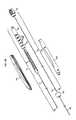
- FIG. 1Ais a perspective view of one exemplary embodiment of a device for penetrating tissue
- FIG. 1Bis an exploded view of the device for penetrating tissue shown in FIG. 1A ;
- FIG. 2is a perspective view of a portion of a needle assembly of the device shown in FIGS. 1A-1B ;
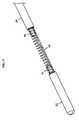
- FIG. 3is a perspective view of a portion of a stylet assembly of the device shown in FIGS. 1A-1B ;
- FIG. 4is a perspective view of the needle assembly and stylet assembly of the device shown in FIGS. 1A-1B ;
- FIG. 5Ais a perspective view of another embodiment of a device for penetrating tissue having a tissue grasping assembly inserted through the device and adapted to grasp and hold tissue during tissue penetration by the device;
- FIG. 5Bis a perspective view of the tissue grasping assembly shown in FIG. 5A ;
- FIG. 6Ais a perspective view of a distal portion of another embodiment of a device for penetrating tissue having an expandable member for increasing the size of a puncture formed in tissue using the device;
- FIG. 6Bis a distal perspective view of the device shown in FIG. 6A with an inflated view of the expandable member;
- FIG. 7Ais a perspective view of a distal portion of the device of FIGS. 5A-5B positioned adjacent to tissue, and showing the tissue grasping members penetrated through tissue to grasp and hold the tissue;
- FIG. 7Bis a side view of the device and tissue of FIGS. 1A-1B showing a tissue-penetrating tip penetrated through tissue with a plunger in a proximal position;
- FIG. 7Cis a side view of the device and tissue of FIG. 7B after the device has penetrated through the tissue, showing the plunger returned to a distal position;
- FIG. 8Ais a side view of the device of FIGS. 6A-6B showing the device penetrated through the tissue and showing the expandable member positioned in a puncture hole formed in the tissue;
- FIG. 8Bis a side view of the device and tissue of FIG. 8A , showing the expandable member inflated in the puncture hole formed in the tissue to increase the size of the puncture hole;
- FIG. 9is a side view of the device of FIGS. 1A-1B showing the device penetrated through the tissue and a guidewire positioned through the device.
- a tissue-penetrating devicehaving a hollow elongate needle shaft with a tissue-penetrating tip at a distal end thereof for penetrating tissue.
- the devicecan also include a plunger disposed within at least a portion of the elongate needle shaft and configured to move relative to the tip to allow the tip to penetrate tissue only when the plunger and tip are advanced into the tissue to be penetrated.
- the plungerthus functions to provide a blunt-tip configuration until it is desired to advance and penetrate the device through tissue. While the device can be used in a variety of applications, it is preferably used in endoscopic or laparoscopic surgery.
- the devicecan be inserted translumenally, and then penetrated through a tissue surface, such as the stomach or colon, to form a puncture hole in the tissue to provide access to other areas of the body, such as the abdominal cavity.
- the plungeris particularly advantageous as it allows the device to penetrate through tissue, while preventing puncture or injury to adjacent tissue, such as organs disposed within the stomach cavity.
- FIGS. 1A-1Billustrate one exemplary embodiment of a device for penetrating tissue.
- the device 10generally includes a handle 12 with a needle assembly 14 extending therethrough and extending from a distal end of the handle and configured to be introduced translumenally.
- the needle assembly 14includes a needle shaft 16 slidably disposed within the handle, and a needle 17 extending distally from the needle shaft 16 and having a tissue-penetrating tip 18 formed on or coupled to a distal end thereof for penetrating tissue.
- the device 10also includes a stylet assembly 20 disposed within the needle assembly 14 and configured to protect the tip 18 until the device 10 is positioned against a tissue to be penetrated.
- the stylet assembly 20includes a stylet 24 extending proximally through and distally from the handle 12 and coupled at its proximal end to an end cap 26 , and a plunger 22 disposed distal of the distal end of the stylet 24 for protecting the tip 18 .
- the device 10can also include an outer sheath 28 extending distally from the handle 12 that is configured to receive and house the needle and stylet assemblies 14 , 20 to thereby protect a body lumen or other instrument in which the device 10 is inserted from the tissue-penetrating tip 18 .
- the plunger 22 on the stylet assembly 20can be positioned relative to the tissue-penetrating tip 18 of the needle assembly 14 to render the tip 18 blunt and prevent it from penetrating tissue.
- the plunger 22can be moved proximally within the tip 18 to allow the tip 18 to penetrating through tissue. Once the tip 18 penetrates through tissue, the plunger 22 can return to its initial, distal position to protect the tip 18 and prevent unintentional puncture of adjacent tissue.
- the handle 12 of the device 10can have any shape and size, but it is preferably adapted to facilitate grasping and manipulation of the device 10 .
- the handle 12has an elongate cylindrical configuration.
- the handle 12can be formed from multiple pieces, or it can have a unitary configuration.
- the handle 12includes two halves 12 a , 12 b that mate together and that house the proximal portions of the needle assembly 14 and the stylet assembly 20 .
- a distal end cap 12 ccan be used to mate the distal ends of the assemblies 14 , 20 .
- the end cap 12 cas well as the proximal end of then handle 12 , can include openings formed therein for receiving the assemblies 14 , 20 therethrough.
- the device 10can also include an outer sheath 28 that houses the distal portion of the needle and stylet assemblies 14 , 20 .
- the outer sheath 28can be flexible or rigid, but in an exemplary embodiment, a distal end of the device 10 is adapted to be inserted translumenally, and therefore the outer sheath 28 can be semi-flexible or flexible to allow insertion through a tortuous lumen. As shown in FIGS. 1A-1B , the outer sheath 28 is fixed to and extends distally from the distal end of the end cap 12 c of the handle 12 .
- the length of the outer sheath 28can vary depending on the intended use of the device 10 , but in an illustrated embodiment the outer sheath 28 has an elongate length that is adapted for use translumenally. A person skilled in the art will appreciate that the outer sheath 28 is not a necessary component for the device 10 to penetrate tissue and can be omitted.
- the handle 12can also include other features, such as a dowel 30 coupled to an inner wall of the handle 12 that is configured to control a position of the tissue-penetrating tip 18 with respect to the handle 12 and the outer sheath 28 , as will be discussed in more detail below.
- the needle assembly 14 of the device 10can also have a variety of configurations, and various portions of the assembly 14 can be flexible or rigid.
- a distal end of the needle assembly 14i.e., the needle 17
- the needle 17is adapted to be inserted translumenally, and therefore at least portions of the needle 17 extending from the handle 12 are semi-flexible or flexible to allow insertion through a tortuous lumen.
- the needle 17can be made from a variety of biocompatible materials that have properties sufficient to enable portions of the needle 17 extending from the handle 12 to be inserted and moved within channels of a body lumen.
- the needle 17can also have a length that can vary depending on the intended use of the device, but in an exemplary embodiment the length is adapted for use translumenally.
- a diameter of the needle 17can also vary, but the diameter is preferably sufficient to slidably receive the plunger 22 of the stylet assembly 20 .
- the needle 17can also include a tissue-penetrating tip 18 .
- the tip 18can have any shape or size, but it is preferably configured to allow the tip 18 to penetrate tissue.
- FIG. 7Billustrates an angled tip.
- the tissue-penetrating tip 18can also be configured to penetrate tissue by cutting.
- the tip 18can be a sharpened tip that is adapted to penetrate the tissue by the force of the device 10 as it is advances through tissue.
- the tissue-penetrating tip 18can have a variety of other configurations and it can be adapted to treat tissue in a variety of ways.
- the tip 18can be blunt and/or tissue penetration can be effected or assisted by electrical energy.
- the proximal end of the needle assembly 14can include a needle shaft 16 that is coupled to the needle 17 .
- the needle shaft 16can have a variety of configurations, but in the illustrated embodiment, the needle shaft 16 is slidably movable in the handle 12 to allow a position of the tissue-penetrating tip 18 to be adjusted with respect to the outer sheath 28 .
- movement of the needle shaft 16 within the handle 12can be used to move the tip 18 between a retracted position, in which it is fully retained within the outer sheath 28 , and an extended position, in which the tip 18 extends beyond the distal end of the outer sheath 28 .
- the needle assembly 14can, in other embodiments, be fixedly coupled to or formed integrally with the handle 12 .
- the needle shaft 16can also include a depth gauge 32 formed on or coupled to a proximal end thereof and adapted to indicate a depth of the tip 18 relative to the outer sheath 28 .
- the depth gauge 32can include a keyed track 33 formed therein that is adapted to position the tip 18 at various predetermined locations.
- the keys 36are radial slots formed along the length of the track 33 and are adapted to receive a dowel 30 which is coupled to an inner wall of the handle 12 .
- the dowel 30can be locked in the various keys 36 to position the tip 18 relative to the outer sheath 28 .
- the needle shaft 16is rotated to position the dowel 30 within a longitudinal slot 34 , and it is moved longitudinally to slide the needle assembly 14 relative to the handle 12 and thereby adjust the position of the tissue-penetrating tip 18 .
- the shaft 16is rotated to lock the dowel 30 in another key 36 in the track 33 and thereby maintain the needle assembly 14 in a fixed position relative to the handle 12 and the outer sheath 28 .
- the depth gauge 32can also include markings to indicate the depth of the tip 18 . As shown, the depth gauge 32 includes five keys 36 , and thus five marking 38 along its length.
- these markings 38are defined as the values 0-4, but any types of markings to indicate the varying depth levels of the tip 18 are sufficient.
- a person skilled in the artwill appreciate that a variety of other techniques can be used to adjust a depth of the tip 18 relative to the outer sheath 28 .
- the stylet assembly 20is disposed within the needle assembly 14 and can have a variety of sizes and configurations.
- the stylet assembly 20includes a stylet 24 and a plunger 22 that are movably coupled to one another and that have a length that allows them to extend through the handle 12 to a position proximal to the distal-most end of the tissue-penetration tip 18 to protect the tip 18 when the device 10 is not in contact with tissue.
- the plunger 22 at the distal endis adapted to protect the tissue-penetrating tip 18 when the device is not in contact with tissue.
- the plunger 22can have various shapes and sizes, but in the illustrated embodiment, it has a cylindrical configuration with a blunt distal end.
- the plunger 22is movable relative to the tissue-penetrating tip 18 between a distal position in which the plunger 22 is distal of the tissue-penetrating tip 18 to prevent tissue penetration, and a proximal position in which the plunger 22 is proximal of or adjacent to the tissue-penetrating tip 18 to allow the tip to penetrate tissue.
- the elongate stylet 24extends proximally from the plunger 22 and is preferably semi-flexible or flexible to allow insertion through a tortuous lumen.
- the plunger 22 and the stylet 24can be movably coupled to one another to allow the plunger 22 to move between the proximal and distal positions.
- the device 10can include a biasing element that extends between the plunger 22 and the stylet 24 and that is adapted to bias the plunger 22 to the distal position.
- the biasing elementcan be a spring 40 , as shown in FIG. 3 , for biasing the plunger 22 to the distal position.
- the spring 40is coupled between a distal end of the elongate stylet 24 and a proximal end of the plunger 22 .
- a distal end of the spring 40is coupled to a plunger post 42 formed on the plunger 22 and its proximal end is coupled to a stylet post 44 formed on the elongate stylet 24 .
- the biasing force of the spring 40 on the plunger 22can be overcome by advancing the plunger 22 against a tissue surface, allowing the plunger 22 to retract into the proximal position when it is in contact with a tissue.
- the spring 40compresses and the plunger 22 moves proximally to expose the tip 18 to allow it to penetrate the tissue.
- the force of the tissue on the plunger 22is removed and the plunger 22 moves distally to protect the tip 18 and prevent further tissue penetration.
- the devicedoes not need to include a stylet, and the proximal end of the biasing element can rest against a flange formed on an inner wall of the needle 17 .
- the stylet assembly 20is disposed within the needle assembly 14 with the plunger 22 extending adjacent to or distally from the tissue-penetrating tip 18 when the plunger 22 is in the distal position.
- the assemblies 14 , 20can optionally be releasably attached to each other to allow them to move together with respect to the outer sheath 28 to maintain the position of the plunger 22 with respect to the tip 18 .
- the stylet 24is coupled to an end cap 26 , which can releasably mate to the proximal end of the needle shaft 16 .
- the needle shaft 16can be coupled to the end cap 26 using a variety of mating techniques, such as a luer lock, threads, a snap fit engagement, an interference fit, and a magnetic engagement.
- the releasable attachment between the stylet assembly 20 and the needle assembly 14can also allow the stylet assembly 20 to be removed from the needle assembly 14 to allow irrigation fluid or a guidewire to be passed therethrough.
- the stylet assembly 20can be cannulated for receiving irrigation fluid or a guidewire 70 after tissue penetration, or the guidewire 70 can be preloaded in the stylet assembly 20 , as shown in FIG. 9 .
- the guidewire 70can be positioned through the puncture hole made in the tissue by the tissue-penetrating tip 18 .
- the device 10can be removed, leaving the guidewire 70 in place.
- a variety of devices and surgical instrumentscan then be guided along the guidewire 70 to facilitate a number of surgical procedures that can be performed at the site of the penetrated tissue.
- the device of FIGS. 1A-1Bcan also be configured to receive one or more tissue grasping members therethrough.
- the tissue grasping member(s)can have various configurations, but it is preferably configured to grasp and hold tissue while a tissue-penetrating tip 18 ′ is advanced through the tissue.
- FIGS. 5A-5Billustrate two tissue grasping members 50 ′, 52 ′ extending between the outer sheath 28 ′ and the needle assembly 14 ′ to be positioned through the tissue.
- Each tissue grasping member 50 ′, 52 ′has a hook-shaped distal end that is configured to penetrate and grasp tissue.
- the tissue grasping members 50 ′, 52 ′are movable between a proximal position in which they are disposed within the outer sheath 28 ′, and a distal position in which they extend from the outer sheath 28 ′ to allow the members 50 ′, 52 ′ to penetrate tissue.
- the members 50 ′, 52 ′are preferably formed from a shape memory material to allow the distal ends of the members 50 ′, 52 ′ to curl when extended from the distal end of the outer sheath 28 ′, and to deform and straighten out when the members 50 ′, 52 ′ are pulled back into the outer sheath 28 ′.
- a knob 54 ′can be slidably disposed in a slot in the handle 12 ′ and can be coupled to the proximal end of the members 50 ′, 52 ′ to control their movement between the proximal and distal positions.
- a person skilled in the artwill appreciate that any type of control device can be used to control the movement of the tissue grasping members 50 ′, 52 ′, and that the control device can be positioned on the device, such as on the handle, or separate from the device.
- the device disclosed hereincan also include an expandable member that is adapted to increase the size of the puncture formed in tissue by the tissue-penetrating tip of the device.
- FIGS. 6A-6Billustrate one embodiment of an expandable member disposed on a tissue-penetrating device 10 ′′.
- the expandable memberis in the form of a dilating balloon 60 ′′ that is configured to be inflated to expand the size of the puncture hole.
- the balloon 60 ′′can be disposed at various locations, but FIGS. 6A-6B illustrate the balloon 60 ′′ disposed on an outer sheath 28 ′′.
- the balloon 60 ′′can then be inflated using, for example, fluid or air introduced through an inflation lumen formed in and extending along the outer sheath 28 ′′.
- any inflation lumencan be used to inflate the balloon 60 ′′, including a lumen internal or external to the outer sheath 28 ′′.
- the device 10 ′′can include an inflation port 62 ′′ coupled to or formed on a handle 12 ′′.
- the device 10 ′′can be advanced to position the deflated balloon 60 ′′, shown in FIG. 6A , within the puncture site.
- the balloon 60 ′′is inflated, shown in FIG.
- the expandable membercan be associated with other devices, such as the guidewire described above.
- the expandable membercan be disposed on or positioned over the guidewire to allow for positioning the expandable member within the puncture site.
- FIGS. 7A-8Billustrate one exemplary method for penetrating a target tissue.
- the device 10is inserted translumenally into a patient and passed to a target tissue to be penetrated.
- the tissue grasping members 50 , 52can be moved distally using the knob 54 disposed on the handle 12 to allow the members 50 , 52 to grasp the tissue in order to hold the tissue (only a portion of the tissue penetrated by tissue grasping member 50 is shown).
- the tissue-penetrating tip 18can then be advanced into the tissue, as shown in FIG. 7B .
- the plunger 22will be forced into the proximal position as the plunger 22 is advanced into the target tissue. Once the plunger 22 moves to the proximal position within the needle shaft 16 , the tip 18 can contact and penetrate the tissue. After the tip 18 has penetrated through the target tissue as shown in FIG. 7C , or the device 10 has been moved out of contact with the target tissue, the pressure is removed from the plunger 22 , thereby allowing the plunger 22 to return to the distal position to protect adjacent tissue from being penetrated by the tissue-penetrating tip 18 . The plunger 22 and needle shaft 16 can also be retracted relative to the sheath 28 such that the tip 18 and plunger 22 are contained with the sheath 28 to prevent damage to adjacent tissues.
- the tissue grasping members 50 , 52can then be removed from the tissue by retracting the members 50 , 52 relative to the outer sheath 28 .
- an expandable member disposed on the outer sheath 28can be positioned within the puncture site formed in the tissue by the tip 18 to expand the size of the puncture hole, shown in FIG. 8B .
- a guidewirecan be inserted through the stylet assembly 20 , or the stylet assembly 20 can be removed and replaced with a guidewire.
- the guidewirecan function as a placeholder, allowing the device 10 to be removed while the guidewire remains positioned through the puncture.
- An expandable member, or various other devices,can then be passed over the guidewire.
- an endoscopecan be passed through the esophagus and positioned within the stomach, and a tissue-penetrating device, such as the devices described in FIGS. 1A-1B , can be introduced through a working channel of the endoscope and used to create a puncture hole in the stomach wall by penetrating the tissue of the stomach wall.
- a tissue-penetrating devicesuch as the devices described in FIGS. 1A-1B
- the tip and plungercan be moved within the outer sheath using the depth gauge of the needle assembly before inserting the device into the endoscope.
- the tissue grasping memberscan be moved distally to allow the members to grasp and hold the tissue, and the device can be advanced to penetrate the tissue-penetrating tip through the tissue.
- an expandable member on the outer sheathcan be used to increase the puncture site.
- the endoscopecan then be advanced against the expandable member and through the puncture.
- a guidewirecan be preloaded within the stylet assembly or it can be feed through the device to the site of the puncture hole created in the stomach wall, and the tissue-penetrating device can be removed, leaving the guidewire as a placeholder.
- An expandable member disposed on the guidewire or positioned over the guidewirecan be positioned within the puncture site.
- the endoscopecan be advanced into the expandable member to push the expandable member and the endoscope through the puncture hole and into the abdominal cavity. Additional instruments and devices can then be passed through the working channel of the endoscope to perform various procedures.
- a guidewire and separate expandable memberare not necessary and that other techniques can be used to insert an endoscope or other devices through the puncture.
Landscapes
- Health & Medical Sciences (AREA)
- Surgery (AREA)
- Life Sciences & Earth Sciences (AREA)
- Medical Informatics (AREA)
- Nuclear Medicine, Radiotherapy & Molecular Imaging (AREA)
- Engineering & Computer Science (AREA)
- Biomedical Technology (AREA)
- Heart & Thoracic Surgery (AREA)
- Pathology (AREA)
- Molecular Biology (AREA)
- Animal Behavior & Ethology (AREA)
- General Health & Medical Sciences (AREA)
- Public Health (AREA)
- Veterinary Medicine (AREA)
- Surgical Instruments (AREA)
- Endoscopes (AREA)
Abstract
Description
Claims (6)
Priority Applications (8)
| Application Number | Priority Date | Filing Date | Title |
|---|---|---|---|
| US11/380,958US8328836B2 (en) | 2006-05-01 | 2006-05-01 | Flexible endoscopic safety needle |
| AU2007201668AAU2007201668B2 (en) | 2006-05-01 | 2007-04-16 | Flexible endoscopic safety needle |
| JP2007119131AJP5345297B2 (en) | 2006-05-01 | 2007-04-27 | Flexible endoscope safety needle |
| CN2007101077640ACN101066224B (en) | 2006-05-01 | 2007-04-29 | Flexible endoscopic safety needle |
| DE602007003255TDE602007003255D1 (en) | 2006-05-01 | 2007-04-30 | Bendable endoscopic safety pin |
| CA2586902ACA2586902C (en) | 2006-05-01 | 2007-04-30 | Flexible endoscopic safety needle |
| EP07251803AEP1867291B2 (en) | 2006-05-01 | 2007-04-30 | Flexible endoscopic safety needle |
| HK08104305.4AHK1114322B (en) | 2006-05-01 | 2008-04-16 | Flexible endoscopic safety needle |
Applications Claiming Priority (1)
| Application Number | Priority Date | Filing Date | Title |
|---|---|---|---|
| US11/380,958US8328836B2 (en) | 2006-05-01 | 2006-05-01 | Flexible endoscopic safety needle |
Publications (2)
| Publication Number | Publication Date |
|---|---|
| US20070255306A1 US20070255306A1 (en) | 2007-11-01 |
| US8328836B2true US8328836B2 (en) | 2012-12-11 |
Family
ID=38649276
Family Applications (1)
| Application Number | Title | Priority Date | Filing Date |
|---|---|---|---|
| US11/380,958Expired - Fee RelatedUS8328836B2 (en) | 2006-05-01 | 2006-05-01 | Flexible endoscopic safety needle |
Country Status (7)
| Country | Link |
|---|---|
| US (1) | US8328836B2 (en) |
| EP (1) | EP1867291B2 (en) |
| JP (1) | JP5345297B2 (en) |
| CN (1) | CN101066224B (en) |
| AU (1) | AU2007201668B2 (en) |
| CA (1) | CA2586902C (en) |
| DE (1) | DE602007003255D1 (en) |
Cited By (24)
| Publication number | Priority date | Publication date | Assignee | Title |
|---|---|---|---|---|
| US8992579B1 (en) | 2011-03-08 | 2015-03-31 | Nuvasive, Inc. | Lateral fixation constructs and related methods |
| US9011431B2 (en) | 2009-01-12 | 2015-04-21 | Ethicon Endo-Surgery, Inc. | Electrical ablation devices |
| US9060815B1 (en) | 2012-03-08 | 2015-06-23 | Nuvasive, Inc. | Systems and methods for performing spine surgery |
| US9078662B2 (en) | 2012-07-03 | 2015-07-14 | Ethicon Endo-Surgery, Inc. | Endoscopic cap electrode and method for using the same |
| USD735333S1 (en) | 2013-06-26 | 2015-07-28 | C. R. Bard, Inc. | Biopsy device |
| USD735332S1 (en) | 2013-03-06 | 2015-07-28 | C. R. Bard, Inc. | Biopsy device |
| USD737440S1 (en) | 2013-03-07 | 2015-08-25 | C. R. Bard, Inc. | Biopsy device |
| US9277957B2 (en) | 2012-08-15 | 2016-03-08 | Ethicon Endo-Surgery, Inc. | Electrosurgical devices and methods |
| US9375268B2 (en) | 2007-02-15 | 2016-06-28 | Ethicon Endo-Surgery, Inc. | Electroporation ablation apparatus, system, and method |
| US9427255B2 (en) | 2012-05-14 | 2016-08-30 | Ethicon Endo-Surgery, Inc. | Apparatus for introducing a steerable camera assembly into a patient |
| US9517089B1 (en) | 2013-10-08 | 2016-12-13 | Nuvasive, Inc. | Bone anchor with offset rod connector |
| US9545290B2 (en) | 2012-07-30 | 2017-01-17 | Ethicon Endo-Surgery, Inc. | Needle probe guide |
| US9572623B2 (en) | 2012-08-02 | 2017-02-21 | Ethicon Endo-Surgery, Inc. | Reusable electrode and disposable sheath |
| US9883910B2 (en) | 2011-03-17 | 2018-02-06 | Eticon Endo-Surgery, Inc. | Hand held surgical device for manipulating an internal magnet assembly within a patient |
| US9968338B2 (en) | 2012-11-21 | 2018-05-15 | C. R. Bard, Inc. | Core needle biopsy device |
| US10098691B2 (en) | 2009-12-18 | 2018-10-16 | Ethicon Endo-Surgery, Inc. | Surgical instrument comprising an electrode |
| US10098527B2 (en) | 2013-02-27 | 2018-10-16 | Ethidcon Endo-Surgery, Inc. | System for performing a minimally invasive surgical procedure |
| US10105141B2 (en) | 2008-07-14 | 2018-10-23 | Ethicon Endo-Surgery, Inc. | Tissue apposition clip application methods |
| US10258406B2 (en) | 2011-02-28 | 2019-04-16 | Ethicon Llc | Electrical ablation devices and methods |
| US10278761B2 (en) | 2011-02-28 | 2019-05-07 | Ethicon Llc | Electrical ablation devices and methods |
| US10314649B2 (en) | 2012-08-02 | 2019-06-11 | Ethicon Endo-Surgery, Inc. | Flexible expandable electrode and method of intraluminal delivery of pulsed power |
| US10314603B2 (en) | 2008-11-25 | 2019-06-11 | Ethicon Llc | Rotational coupling device for surgical instrument with flexible actuators |
| US10413313B2 (en) | 2013-09-27 | 2019-09-17 | Release Medical, Inc. | Tissue incision device |
| US10779882B2 (en) | 2009-10-28 | 2020-09-22 | Ethicon Endo-Surgery, Inc. | Electrical ablation devices |
Families Citing this family (66)
| Publication number | Priority date | Publication date | Assignee | Title |
|---|---|---|---|---|
| JP3987312B2 (en)* | 2001-08-31 | 2007-10-10 | 株式会社東芝 | Semiconductor device manufacturing apparatus and manufacturing method, and semiconductor manufacturing apparatus cleaning method |
| US7850660B2 (en)* | 2003-12-19 | 2010-12-14 | Ethicon Endo-Surgery, Inc. | Implantable medical device with simultaneous attachment mechanism and method |
| US8715243B2 (en) | 2003-06-16 | 2014-05-06 | Ethicon Endo-Surgery, Inc. | Injection port applier with downward force actuation |
| US7862546B2 (en) | 2003-06-16 | 2011-01-04 | Ethicon Endo-Surgery, Inc. | Subcutaneous self attaching injection port with integral moveable retention members |
| US8162897B2 (en) | 2003-12-19 | 2012-04-24 | Ethicon Endo-Surgery, Inc. | Audible and tactile feedback |
| US7815662B2 (en) | 2007-03-08 | 2010-10-19 | Ethicon Endo-Surgery, Inc. | Surgical suture anchors and deployment device |
| US8075572B2 (en) | 2007-04-26 | 2011-12-13 | Ethicon Endo-Surgery, Inc. | Surgical suturing apparatus |
| US8100922B2 (en) | 2007-04-27 | 2012-01-24 | Ethicon Endo-Surgery, Inc. | Curved needle suturing tool |
| US8568410B2 (en) | 2007-08-31 | 2013-10-29 | Ethicon Endo-Surgery, Inc. | Electrical ablation surgical instruments |
| US8579897B2 (en) | 2007-11-21 | 2013-11-12 | Ethicon Endo-Surgery, Inc. | Bipolar forceps |
| US8262655B2 (en) | 2007-11-21 | 2012-09-11 | Ethicon Endo-Surgery, Inc. | Bipolar forceps |
| US8491455B2 (en) | 2007-10-03 | 2013-07-23 | Bioventrix, Inc. | Treating dysfunctional cardiac tissue |
| US20090112059A1 (en) | 2007-10-31 | 2009-04-30 | Nobis Rudolph H | Apparatus and methods for closing a gastrotomy |
| US8480657B2 (en) | 2007-10-31 | 2013-07-09 | Ethicon Endo-Surgery, Inc. | Detachable distal overtube section and methods for forming a sealable opening in the wall of an organ |
| EP2259729B1 (en)* | 2008-03-04 | 2016-01-06 | Cayenne Medical, Inc. | Arthroscopic meniscal repair systems |
| US8262680B2 (en) | 2008-03-10 | 2012-09-11 | Ethicon Endo-Surgery, Inc. | Anastomotic device |
| US8361100B2 (en) | 2008-03-17 | 2013-01-29 | Ethicon, Inc. | Applicator instruments for the delivery, deployment, and tamponade of hemostats and methods therefor |
| US8366733B2 (en)* | 2008-03-28 | 2013-02-05 | Ethicon, Inc. | Applicator instruments for controlling bleeding at surgical sites and methods therefor |
| US8070759B2 (en) | 2008-05-30 | 2011-12-06 | Ethicon Endo-Surgery, Inc. | Surgical fastening device |
| US8771260B2 (en) | 2008-05-30 | 2014-07-08 | Ethicon Endo-Surgery, Inc. | Actuating and articulating surgical device |
| US8679003B2 (en) | 2008-05-30 | 2014-03-25 | Ethicon Endo-Surgery, Inc. | Surgical device and endoscope including same |
| US8652150B2 (en) | 2008-05-30 | 2014-02-18 | Ethicon Endo-Surgery, Inc. | Multifunction surgical device |
| US8317806B2 (en) | 2008-05-30 | 2012-11-27 | Ethicon Endo-Surgery, Inc. | Endoscopic suturing tension controlling and indication devices |
| US8114072B2 (en) | 2008-05-30 | 2012-02-14 | Ethicon Endo-Surgery, Inc. | Electrical ablation device |
| US8906035B2 (en) | 2008-06-04 | 2014-12-09 | Ethicon Endo-Surgery, Inc. | Endoscopic drop off bag |
| US8403926B2 (en) | 2008-06-05 | 2013-03-26 | Ethicon Endo-Surgery, Inc. | Manually articulating devices |
| US8361112B2 (en) | 2008-06-27 | 2013-01-29 | Ethicon Endo-Surgery, Inc. | Surgical suture arrangement |
| US8262563B2 (en) | 2008-07-14 | 2012-09-11 | Ethicon Endo-Surgery, Inc. | Endoscopic translumenal articulatable steerable overtube |
| US8425402B2 (en)* | 2008-07-21 | 2013-04-23 | Bioventrix, Inc. | Cardiac anchor structures, methods, and systems for treatment of congestive heart failure and other conditions |
| US8211125B2 (en) | 2008-08-15 | 2012-07-03 | Ethicon Endo-Surgery, Inc. | Sterile appliance delivery device for endoscopic procedures |
| US8529563B2 (en) | 2008-08-25 | 2013-09-10 | Ethicon Endo-Surgery, Inc. | Electrical ablation devices |
| US20100048990A1 (en)* | 2008-08-25 | 2010-02-25 | Ethicon Endo-Surgery, Inc. | Endoscopic needle for natural orifice translumenal endoscopic surgery |
| US8241204B2 (en) | 2008-08-29 | 2012-08-14 | Ethicon Endo-Surgery, Inc. | Articulating end cap |
| US8480689B2 (en) | 2008-09-02 | 2013-07-09 | Ethicon Endo-Surgery, Inc. | Suturing device |
| US8409200B2 (en) | 2008-09-03 | 2013-04-02 | Ethicon Endo-Surgery, Inc. | Surgical grasping device |
| US20100056862A1 (en)* | 2008-09-03 | 2010-03-04 | Ethicon Endo-Surgery, Inc. | Access needle for natural orifice translumenal endoscopic surgery |
| US8114119B2 (en) | 2008-09-09 | 2012-02-14 | Ethicon Endo-Surgery, Inc. | Surgical grasping device |
| US8337394B2 (en) | 2008-10-01 | 2012-12-25 | Ethicon Endo-Surgery, Inc. | Overtube with expandable tip |
| JP5162707B2 (en)* | 2008-10-21 | 2013-03-13 | カイエン メディカル インコーポレイテッド | Meniscal treatment system |
| US8172772B2 (en) | 2008-12-11 | 2012-05-08 | Ethicon Endo-Surgery, Inc. | Specimen retrieval device |
| CA2748008C (en)* | 2008-12-22 | 2016-09-13 | Wilson-Cook Medical, Inc. | Electrosurgical rotating cutting device |
| US8828031B2 (en) | 2009-01-12 | 2014-09-09 | Ethicon Endo-Surgery, Inc. | Apparatus for forming an anastomosis |
| US8252057B2 (en)* | 2009-01-30 | 2012-08-28 | Ethicon Endo-Surgery, Inc. | Surgical access device |
| US9226772B2 (en)* | 2009-01-30 | 2016-01-05 | Ethicon Endo-Surgery, Inc. | Surgical device |
| US8037591B2 (en) | 2009-02-02 | 2011-10-18 | Ethicon Endo-Surgery, Inc. | Surgical scissors |
| AU2010242820B2 (en)* | 2009-05-01 | 2014-12-11 | Cayenne Medical, Inc. | Meniscal repair systems and methods |
| US8608652B2 (en) | 2009-11-05 | 2013-12-17 | Ethicon Endo-Surgery, Inc. | Vaginal entry surgical devices, kit, system, and method |
| US20110112434A1 (en)* | 2009-11-06 | 2011-05-12 | Ethicon Endo-Surgery, Inc. | Kits and procedures for natural orifice translumenal endoscopic surgery |
| US8496574B2 (en) | 2009-12-17 | 2013-07-30 | Ethicon Endo-Surgery, Inc. | Selectively positionable camera for surgical guide tube assembly |
| US8353487B2 (en) | 2009-12-17 | 2013-01-15 | Ethicon Endo-Surgery, Inc. | User interface support devices for endoscopic surgical instruments |
| US8506564B2 (en) | 2009-12-18 | 2013-08-13 | Ethicon Endo-Surgery, Inc. | Surgical instrument comprising an electrode |
| US9005198B2 (en) | 2010-01-29 | 2015-04-14 | Ethicon Endo-Surgery, Inc. | Surgical instrument comprising an electrode |
| EP3305209B1 (en) | 2010-06-09 | 2025-01-08 | C.R. Bard Inc. | Instruments for delivering transfascial sutures and transfascial suture assemblies. |
| US10092291B2 (en) | 2011-01-25 | 2018-10-09 | Ethicon Endo-Surgery, Inc. | Surgical instrument with selectively rigidizable features |
| US9314620B2 (en) | 2011-02-28 | 2016-04-19 | Ethicon Endo-Surgery, Inc. | Electrical ablation devices and methods |
| US20120259203A1 (en)* | 2011-04-08 | 2012-10-11 | Paul David Devereux | Sheath Retractable Flexible Injection Needle |
| KR101267440B1 (en) | 2011-04-21 | 2013-05-31 | 주식회사 에스앤지바이오텍 | medical needle device |
| WO2013062933A1 (en) | 2011-10-24 | 2013-05-02 | C.R. Bard, Inc. | Instruments for delivering transfascial sutures, transfascial suture assemblies and methods of transfascial suturing |
| US9924938B2 (en) | 2011-11-07 | 2018-03-27 | C.R. Bard, Inc. | Instruments for delivering transfascial sutures and methods of transfascial suturing |
| US8986199B2 (en) | 2012-02-17 | 2015-03-24 | Ethicon Endo-Surgery, Inc. | Apparatus and methods for cleaning the lens of an endoscope |
| EP2827935B1 (en)* | 2012-03-18 | 2018-01-10 | Traumatek Solutions B.V. | Devices for endovascular access and therapy |
| US9149585B2 (en)* | 2012-04-20 | 2015-10-06 | Cook Medical Technologies Llc | Multi-needle injection device |
| CN105561445B (en)* | 2015-12-19 | 2019-05-21 | 中国人民解放军第四军医大学 | A kind of adjustable endoscope injection device |
| US11406365B2 (en)* | 2017-03-23 | 2022-08-09 | Gyrus Acmi, Inc. | Needle handle with vacuum chamber |
| WO2021076547A1 (en)* | 2019-10-15 | 2021-04-22 | Medtronic Vascular, Inc. | Protection devices and methods for balloon catheter-type devices |
| EP4129216A4 (en)* | 2020-03-23 | 2023-11-29 | Gibello Alejandro Fernández | Instrument comprising a needle for ultrasound-guided surgery provided with retractable scalpel |
Citations (33)
| Publication number | Priority date | Publication date | Assignee | Title |
|---|---|---|---|---|
| US3727613A (en) | 1970-10-09 | 1973-04-17 | Voys Inc Le | Safety catheter placement assembly |
| DE2544262A1 (en) | 1975-10-03 | 1977-04-14 | Max Bernhard Ulrich | Catheter for intra:uterine use - has puncturing point and protective and removable hose in longitudinal central channel |
| US4254762A (en)* | 1979-10-23 | 1981-03-10 | Inbae Yoon | Safety endoscope system |
| US4684363A (en) | 1984-10-31 | 1987-08-04 | American Hospital Supply Corporation | Rapidly inflatable balloon catheter and method |
| US5066288A (en)* | 1988-07-06 | 1991-11-19 | Ethicon, Inc. | Safety trocar |
| US5098388A (en)* | 1991-05-02 | 1992-03-24 | Richard Kulkashi | Veress needle assembly |
| US5147316A (en) | 1990-11-19 | 1992-09-15 | Castillenti Thomas A | Laparoscopic trocar with self-locking port sleeve |
| JPH05168644A (en) | 1991-01-15 | 1993-07-02 | Ethicon Inc | Trocar |
| US5226426A (en)* | 1990-12-18 | 1993-07-13 | Inbae Yoon | Safety penetrating instrument |
| US5295977A (en)* | 1993-05-11 | 1994-03-22 | Symbiosis Corporation | Trocar catheter for drainage |
| US5312351A (en)* | 1993-01-29 | 1994-05-17 | Gerrone Carmen J | Combined pneumo-needle and trocar apparatus |
| US5324268A (en) | 1991-12-16 | 1994-06-28 | Inbae Yoon | Trocar with safety shield |
| US5401247A (en) | 1990-12-18 | 1995-03-28 | Yoon; Inbae | Safety penetrating instrument |
| WO1996026752A1 (en) | 1995-02-28 | 1996-09-06 | Inbae Yoon | Retractable safety penetrating instrument with safety probe |
| US5573545A (en) | 1993-06-24 | 1996-11-12 | Yoon; Inbae | Safety penetrating instrument with safety member and cannula moving during penetration and triggered cannula and/or safety member protrusion |
| US5578053A (en) | 1993-06-24 | 1996-11-26 | Yoon; Inbae | Safety needle instrument having a triggered safety member |
| US5601533A (en) | 1994-06-07 | 1997-02-11 | Gip Medizin Technik Gmbh | Endoscopic puncture needle device |
| JPH09140721A (en) | 1995-11-20 | 1997-06-03 | Olympus Optical Co Ltd | Pneumoperitoneum needle with jacket tube |
| US5713869A (en) | 1995-03-08 | 1998-02-03 | Morejon; Orlando | Trocar assembly |
| US5836913A (en) | 1997-05-02 | 1998-11-17 | Innerdyne, Inc. | Device and method for accessing a body cavity |
| US5984917A (en) | 1995-06-07 | 1999-11-16 | Ep Technologies, Inc. | Device and method for remote insertion of a closed loop |
| US6080174A (en) | 1993-03-05 | 2000-06-27 | Innerdyne, Inc. | Trocar system having expandable port |
| US6156006A (en) | 1997-10-17 | 2000-12-05 | Circon Corporation | Medical instrument system for piercing through tissue |
| WO2002100286A1 (en) | 2001-06-12 | 2002-12-19 | Senorx, Inc. | Tissue accessing and anchoring device and method |
| US20040002683A1 (en)* | 2002-06-26 | 2004-01-01 | Nicholson Thomas J. | Percutaneous medical insertion device |
| WO2004043272A1 (en) | 2002-11-14 | 2004-05-27 | Sydney West Area Health Service | An intramural needle-tipped surgical device |
| US6743206B1 (en) | 2000-03-07 | 2004-06-01 | Syntheon, Llc | Endoscopic needle |
| US20050080435A1 (en)* | 2002-09-20 | 2005-04-14 | Kevin Smith | Tissue retractor and method for using the retractor |
| US20050143763A1 (en) | 2003-12-29 | 2005-06-30 | Ortiz Mark S. | Device and method for intralumenal anastomosis |
| US6918871B2 (en) | 2003-06-19 | 2005-07-19 | Ethicon Endo-Surgery, Inc. | Method for accessing cavity |
| US20050215855A1 (en)* | 2004-03-29 | 2005-09-29 | Fujinon Corporation | Endoscope apparatus |
| US20080269781A1 (en)* | 2005-04-21 | 2008-10-30 | Tyco Healthcare Group Lp | Surgical Fastener, Surgical Fastener Kit and Removing Tool |
| US20080269566A1 (en)* | 2007-04-30 | 2008-10-30 | Ethicon Endo-Surgery, Inc. | Endoscopic device |
Family Cites Families (2)
| Publication number | Priority date | Publication date | Assignee | Title |
|---|---|---|---|---|
| JP4527058B2 (en)* | 2003-01-30 | 2010-08-18 | 住友ベークライト株式会社 | Puncture balloon |
| US7322999B2 (en)* | 2003-05-09 | 2008-01-29 | Atrion Medical Products, Inc. | Tissue punch and method for creating an anastomosis for locating a bypass graft |
- 2006
- 2006-05-01USUS11/380,958patent/US8328836B2/ennot_activeExpired - Fee Related
- 2007
- 2007-04-16AUAU2007201668Apatent/AU2007201668B2/ennot_activeCeased
- 2007-04-27JPJP2007119131Apatent/JP5345297B2/ennot_activeExpired - Fee Related
- 2007-04-29CNCN2007101077640Apatent/CN101066224B/ennot_activeExpired - Fee Related
- 2007-04-30EPEP07251803Apatent/EP1867291B2/ennot_activeCeased
- 2007-04-30CACA2586902Apatent/CA2586902C/ennot_activeExpired - Fee Related
- 2007-04-30DEDE602007003255Tpatent/DE602007003255D1/enactiveActive
Patent Citations (35)
| Publication number | Priority date | Publication date | Assignee | Title |
|---|---|---|---|---|
| US3727613A (en) | 1970-10-09 | 1973-04-17 | Voys Inc Le | Safety catheter placement assembly |
| DE2544262A1 (en) | 1975-10-03 | 1977-04-14 | Max Bernhard Ulrich | Catheter for intra:uterine use - has puncturing point and protective and removable hose in longitudinal central channel |
| US4254762A (en)* | 1979-10-23 | 1981-03-10 | Inbae Yoon | Safety endoscope system |
| US4684363A (en) | 1984-10-31 | 1987-08-04 | American Hospital Supply Corporation | Rapidly inflatable balloon catheter and method |
| US5066288A (en)* | 1988-07-06 | 1991-11-19 | Ethicon, Inc. | Safety trocar |
| US5147316A (en) | 1990-11-19 | 1992-09-15 | Castillenti Thomas A | Laparoscopic trocar with self-locking port sleeve |
| US5586991A (en) | 1990-12-18 | 1996-12-24 | Yoon; Inbae | Safety penetrating instrument |
| US5226426A (en)* | 1990-12-18 | 1993-07-13 | Inbae Yoon | Safety penetrating instrument |
| US5401247A (en) | 1990-12-18 | 1995-03-28 | Yoon; Inbae | Safety penetrating instrument |
| JPH05168644A (en) | 1991-01-15 | 1993-07-02 | Ethicon Inc | Trocar |
| US5098388A (en)* | 1991-05-02 | 1992-03-24 | Richard Kulkashi | Veress needle assembly |
| US5324268A (en) | 1991-12-16 | 1994-06-28 | Inbae Yoon | Trocar with safety shield |
| US5312351A (en)* | 1993-01-29 | 1994-05-17 | Gerrone Carmen J | Combined pneumo-needle and trocar apparatus |
| US6080174A (en) | 1993-03-05 | 2000-06-27 | Innerdyne, Inc. | Trocar system having expandable port |
| US5295977A (en)* | 1993-05-11 | 1994-03-22 | Symbiosis Corporation | Trocar catheter for drainage |
| US5578053A (en) | 1993-06-24 | 1996-11-26 | Yoon; Inbae | Safety needle instrument having a triggered safety member |
| US5573545A (en) | 1993-06-24 | 1996-11-12 | Yoon; Inbae | Safety penetrating instrument with safety member and cannula moving during penetration and triggered cannula and/or safety member protrusion |
| US5601533A (en) | 1994-06-07 | 1997-02-11 | Gip Medizin Technik Gmbh | Endoscopic puncture needle device |
| JPH10506558A (en) | 1995-02-28 | 1998-06-30 | ユーン,インバエ | Retractable safety penetrator with safety probe |
| WO1996026752A1 (en) | 1995-02-28 | 1996-09-06 | Inbae Yoon | Retractable safety penetrating instrument with safety probe |
| US5713869A (en) | 1995-03-08 | 1998-02-03 | Morejon; Orlando | Trocar assembly |
| US5984917A (en) | 1995-06-07 | 1999-11-16 | Ep Technologies, Inc. | Device and method for remote insertion of a closed loop |
| JPH09140721A (en) | 1995-11-20 | 1997-06-03 | Olympus Optical Co Ltd | Pneumoperitoneum needle with jacket tube |
| US5836913A (en) | 1997-05-02 | 1998-11-17 | Innerdyne, Inc. | Device and method for accessing a body cavity |
| US6156006A (en) | 1997-10-17 | 2000-12-05 | Circon Corporation | Medical instrument system for piercing through tissue |
| US6743206B1 (en) | 2000-03-07 | 2004-06-01 | Syntheon, Llc | Endoscopic needle |
| WO2002100286A1 (en) | 2001-06-12 | 2002-12-19 | Senorx, Inc. | Tissue accessing and anchoring device and method |
| US20040002683A1 (en)* | 2002-06-26 | 2004-01-01 | Nicholson Thomas J. | Percutaneous medical insertion device |
| US20050080435A1 (en)* | 2002-09-20 | 2005-04-14 | Kevin Smith | Tissue retractor and method for using the retractor |
| WO2004043272A1 (en) | 2002-11-14 | 2004-05-27 | Sydney West Area Health Service | An intramural needle-tipped surgical device |
| US6918871B2 (en) | 2003-06-19 | 2005-07-19 | Ethicon Endo-Surgery, Inc. | Method for accessing cavity |
| US20050143763A1 (en) | 2003-12-29 | 2005-06-30 | Ortiz Mark S. | Device and method for intralumenal anastomosis |
| US20050215855A1 (en)* | 2004-03-29 | 2005-09-29 | Fujinon Corporation | Endoscope apparatus |
| US20080269781A1 (en)* | 2005-04-21 | 2008-10-30 | Tyco Healthcare Group Lp | Surgical Fastener, Surgical Fastener Kit and Removing Tool |
| US20080269566A1 (en)* | 2007-04-30 | 2008-10-30 | Ethicon Endo-Surgery, Inc. | Endoscopic device |
Non-Patent Citations (5)
| Title |
|---|
| Australian Examiner's Report for Application No. 2007201668 dated Feb. 8, 2012. |
| Chinese Patent Application No. 2007101077640-Office Action dated Jan. 18, 2010. |
| EP Application No. 07251803.8-Extended European Search Report dated Feb. 6, 2008. |
| EP Application No. 07251803.8-Preliminary Opposition Opinion dated Jul. 6, 2011. |
| Japanese Office Action for Application No. 2007-119131, mailed Feb. 28, 2012. |
Cited By (42)
| Publication number | Priority date | Publication date | Assignee | Title |
|---|---|---|---|---|
| US9375268B2 (en) | 2007-02-15 | 2016-06-28 | Ethicon Endo-Surgery, Inc. | Electroporation ablation apparatus, system, and method |
| US10478248B2 (en) | 2007-02-15 | 2019-11-19 | Ethicon Llc | Electroporation ablation apparatus, system, and method |
| US11399834B2 (en) | 2008-07-14 | 2022-08-02 | Cilag Gmbh International | Tissue apposition clip application methods |
| US10105141B2 (en) | 2008-07-14 | 2018-10-23 | Ethicon Endo-Surgery, Inc. | Tissue apposition clip application methods |
| US10314603B2 (en) | 2008-11-25 | 2019-06-11 | Ethicon Llc | Rotational coupling device for surgical instrument with flexible actuators |
| US9011431B2 (en) | 2009-01-12 | 2015-04-21 | Ethicon Endo-Surgery, Inc. | Electrical ablation devices |
| US10004558B2 (en) | 2009-01-12 | 2018-06-26 | Ethicon Endo-Surgery, Inc. | Electrical ablation devices |
| US10779882B2 (en) | 2009-10-28 | 2020-09-22 | Ethicon Endo-Surgery, Inc. | Electrical ablation devices |
| US10098691B2 (en) | 2009-12-18 | 2018-10-16 | Ethicon Endo-Surgery, Inc. | Surgical instrument comprising an electrode |
| US10278761B2 (en) | 2011-02-28 | 2019-05-07 | Ethicon Llc | Electrical ablation devices and methods |
| US10258406B2 (en) | 2011-02-28 | 2019-04-16 | Ethicon Llc | Electrical ablation devices and methods |
| US8992579B1 (en) | 2011-03-08 | 2015-03-31 | Nuvasive, Inc. | Lateral fixation constructs and related methods |
| US9883910B2 (en) | 2011-03-17 | 2018-02-06 | Eticon Endo-Surgery, Inc. | Hand held surgical device for manipulating an internal magnet assembly within a patient |
| US9060815B1 (en) | 2012-03-08 | 2015-06-23 | Nuvasive, Inc. | Systems and methods for performing spine surgery |
| US9579131B1 (en) | 2012-03-08 | 2017-02-28 | Nuvasive, Inc. | Systems and methods for performing spine surgery |
| US11284918B2 (en) | 2012-05-14 | 2022-03-29 | Cilag GmbH Inlernational | Apparatus for introducing a steerable camera assembly into a patient |
| US9427255B2 (en) | 2012-05-14 | 2016-08-30 | Ethicon Endo-Surgery, Inc. | Apparatus for introducing a steerable camera assembly into a patient |
| US10206709B2 (en) | 2012-05-14 | 2019-02-19 | Ethicon Llc | Apparatus for introducing an object into a patient |
| US9788888B2 (en) | 2012-07-03 | 2017-10-17 | Ethicon Endo-Surgery, Inc. | Endoscopic cap electrode and method for using the same |
| US9078662B2 (en) | 2012-07-03 | 2015-07-14 | Ethicon Endo-Surgery, Inc. | Endoscopic cap electrode and method for using the same |
| US9545290B2 (en) | 2012-07-30 | 2017-01-17 | Ethicon Endo-Surgery, Inc. | Needle probe guide |
| US10492880B2 (en) | 2012-07-30 | 2019-12-03 | Ethicon Llc | Needle probe guide |
| US10314649B2 (en) | 2012-08-02 | 2019-06-11 | Ethicon Endo-Surgery, Inc. | Flexible expandable electrode and method of intraluminal delivery of pulsed power |
| US9572623B2 (en) | 2012-08-02 | 2017-02-21 | Ethicon Endo-Surgery, Inc. | Reusable electrode and disposable sheath |
| US10342598B2 (en) | 2012-08-15 | 2019-07-09 | Ethicon Llc | Electrosurgical system for delivering a biphasic waveform |
| US9277957B2 (en) | 2012-08-15 | 2016-03-08 | Ethicon Endo-Surgery, Inc. | Electrosurgical devices and methods |
| US9788885B2 (en) | 2012-08-15 | 2017-10-17 | Ethicon Endo-Surgery, Inc. | Electrosurgical system energy source |
| US11793497B2 (en) | 2012-11-21 | 2023-10-24 | C.R. Bard, Inc. | Core needle biopsy device |
| US9968338B2 (en) | 2012-11-21 | 2018-05-15 | C. R. Bard, Inc. | Core needle biopsy device |
| US11013499B2 (en) | 2012-11-21 | 2021-05-25 | C. R. Bard, Inc. | Core needle biopsy device |
| US10098527B2 (en) | 2013-02-27 | 2018-10-16 | Ethidcon Endo-Surgery, Inc. | System for performing a minimally invasive surgical procedure |
| US11484191B2 (en) | 2013-02-27 | 2022-11-01 | Cilag Gmbh International | System for performing a minimally invasive surgical procedure |
| USD751199S1 (en) | 2013-03-06 | 2016-03-08 | C. R. Bard, Inc. | Biopsy device |
| USD735332S1 (en) | 2013-03-06 | 2015-07-28 | C. R. Bard, Inc. | Biopsy device |
| USD737440S1 (en) | 2013-03-07 | 2015-08-25 | C. R. Bard, Inc. | Biopsy device |
| USD735333S1 (en) | 2013-06-26 | 2015-07-28 | C. R. Bard, Inc. | Biopsy device |
| USD736922S1 (en) | 2013-06-26 | 2015-08-18 | C. R. Bard, Inc. | Biopsy device |
| USD752747S1 (en) | 2013-06-26 | 2016-03-29 | C. R. Bard, Inc. | Biopsy device |
| USD759246S1 (en) | 2013-06-26 | 2016-06-14 | C. R. Bard, Inc. | Biopsy device |
| US10413313B2 (en) | 2013-09-27 | 2019-09-17 | Release Medical, Inc. | Tissue incision device |
| US11464531B2 (en) | 2013-09-27 | 2022-10-11 | Release Medical, Inc. | Tissue incision device |
| US9517089B1 (en) | 2013-10-08 | 2016-12-13 | Nuvasive, Inc. | Bone anchor with offset rod connector |
Also Published As
| Publication number | Publication date |
|---|---|
| DE602007003255D1 (en) | 2009-12-31 |
| AU2007201668B2 (en) | 2012-07-19 |
| US20070255306A1 (en) | 2007-11-01 |
| HK1114322A1 (en) | 2008-10-31 |
| JP2007296350A (en) | 2007-11-15 |
| EP1867291A3 (en) | 2008-03-05 |
| CN101066224A (en) | 2007-11-07 |
| EP1867291B1 (en) | 2009-11-18 |
| CA2586902C (en) | 2015-08-11 |
| EP1867291A2 (en) | 2007-12-19 |
| JP5345297B2 (en) | 2013-11-20 |
| CN101066224B (en) | 2010-12-08 |
| AU2007201668A1 (en) | 2007-11-22 |
| EP1867291B2 (en) | 2013-01-09 |
| CA2586902A1 (en) | 2007-11-01 |
Similar Documents
| Publication | Publication Date | Title |
|---|---|---|
| US8328836B2 (en) | Flexible endoscopic safety needle | |
| US7850686B2 (en) | Protective needle knife | |
| US20090287236A1 (en) | Endoscopic rotary access needle | |
| AU2007201669B2 (en) | Integrated guidewire needle knife device | |
| EP2421451B1 (en) | System for delivering an expanding trocar through a sheath | |
| US7963912B2 (en) | Endoscopic translumenal surgical methods using a sheath | |
| AU2007201956B2 (en) | Endoscopic translumenal surgical systems | |
| US20100048990A1 (en) | Endoscopic needle for natural orifice translumenal endoscopic surgery | |
| EP1852083B1 (en) | Tri-bending sphinctertome | |
| US20100056862A1 (en) | Access needle for natural orifice translumenal endoscopic surgery | |
| US20070260121A1 (en) | Endoscopic Translumenal Surgical Systems | |
| WO2009088689A1 (en) | Flexible tissue-penetration instrument with blunt tip assembly and methods for penetrating tissue | |
| JP2011521680A (en) | System and method for transluminal access | |
| HK1114322B (en) | Flexible endoscopic safety needle | |
| US12232768B2 (en) | Cannula for preventing tumor seeding |
Legal Events
| Date | Code | Title | Description |
|---|---|---|---|
| AS | Assignment | Owner name:ETHICON ENDO-SURGERY, INC., OHIO Free format text:ASSIGNMENT OF ASSIGNORS INTEREST;ASSIGNORS:CONLON, SEAN P.;VAKHARIA, OMAR;LINENKUGEL, DUANE;REEL/FRAME:017875/0166 Effective date:20060629 | |
| ZAAA | Notice of allowance and fees due | Free format text:ORIGINAL CODE: NOA | |
| ZAAB | Notice of allowance mailed | Free format text:ORIGINAL CODE: MN/=. | |
| ZAAA | Notice of allowance and fees due | Free format text:ORIGINAL CODE: NOA | |
| ZAAB | Notice of allowance mailed | Free format text:ORIGINAL CODE: MN/=. | |
| STCF | Information on status: patent grant | Free format text:PATENTED CASE | |
| FPAY | Fee payment | Year of fee payment:4 | |
| FEPP | Fee payment procedure | Free format text:PAYOR NUMBER ASSIGNED (ORIGINAL EVENT CODE: ASPN); ENTITY STATUS OF PATENT OWNER: LARGE ENTITY Free format text:PAYER NUMBER DE-ASSIGNED (ORIGINAL EVENT CODE: RMPN); ENTITY STATUS OF PATENT OWNER: LARGE ENTITY | |
| MAFP | Maintenance fee payment | Free format text:PAYMENT OF MAINTENANCE FEE, 8TH YEAR, LARGE ENTITY (ORIGINAL EVENT CODE: M1552); ENTITY STATUS OF PATENT OWNER: LARGE ENTITY Year of fee payment:8 | |
| FEPP | Fee payment procedure | Free format text:MAINTENANCE FEE REMINDER MAILED (ORIGINAL EVENT CODE: REM.); ENTITY STATUS OF PATENT OWNER: LARGE ENTITY | |
| LAPS | Lapse for failure to pay maintenance fees | Free format text:PATENT EXPIRED FOR FAILURE TO PAY MAINTENANCE FEES (ORIGINAL EVENT CODE: EXP.); ENTITY STATUS OF PATENT OWNER: LARGE ENTITY | |
| STCH | Information on status: patent discontinuation | Free format text:PATENT EXPIRED DUE TO NONPAYMENT OF MAINTENANCE FEES UNDER 37 CFR 1.362 | |
| FP | Lapsed due to failure to pay maintenance fee | Effective date:20241211 |