US8328828B2 - Device for performing an anastomosis - Google Patents
Device for performing an anastomosisDownload PDFInfo
- Publication number
- US8328828B2 US8328828B2US12/228,222US22822208AUS8328828B2US 8328828 B2US8328828 B2US 8328828B2US 22822208 AUS22822208 AUS 22822208AUS 8328828 B2US8328828 B2US 8328828B2
- Authority
- US
- United States
- Prior art keywords
- ring
- clip
- handle
- lower ring
- rings
- Prior art date
- Legal status (The legal status is an assumption and is not a legal conclusion. Google has not performed a legal analysis and makes no representation as to the accuracy of the status listed.)
- Expired - Fee Related, expires
Links
- 230000003872anastomosisEffects0.000titleclaimsabstractdescription25
- 229920002994synthetic fiberPolymers0.000claimsabstractdescription4
- 239000012858resilient materialSubstances0.000claimsdescription5
- 230000002792vascularEffects0.000abstractdescription12
- 206010002329AneurysmDiseases0.000abstractdescription10
- 239000000463materialSubstances0.000abstractdescription4
- 229910052751metalInorganic materials0.000description7
- 239000002184metalSubstances0.000description7
- 241001465754MetazoaSpecies0.000description5
- 230000008901benefitEffects0.000description3
- 210000001015abdomenAnatomy0.000description2
- 210000004556brainAnatomy0.000description2
- 210000000038chestAnatomy0.000description2
- 210000003414extremityAnatomy0.000description2
- 210000003739neckAnatomy0.000description2
- 210000004197pelvisAnatomy0.000description2
- 210000003625skullAnatomy0.000description2
- 210000003462veinAnatomy0.000description2
- 238000012276Endovascular treatmentMethods0.000description1
- 239000004809TeflonSubstances0.000description1
- 229920006362Teflon®Polymers0.000description1
- RTAQQCXQSZGOHL-UHFFFAOYSA-NTitaniumChemical compound[Ti]RTAQQCXQSZGOHL-UHFFFAOYSA-N0.000description1
- 210000000709aortaAnatomy0.000description1
- 210000001367arteryAnatomy0.000description1
- 238000005452bendingMethods0.000description1
- 230000000295complement effectEffects0.000description1
- 238000002059diagnostic imagingMethods0.000description1
- 239000013013elastic materialSubstances0.000description1
- 238000004519manufacturing processMethods0.000description1
- 238000000034methodMethods0.000description1
- 239000004033plasticSubstances0.000description1
- 238000003825pressingMethods0.000description1
- 238000004904shorteningMethods0.000description1
- 238000001356surgical procedureMethods0.000description1
- BFKJFAAPBSQJPD-UHFFFAOYSA-NtetrafluoroetheneChemical compoundFC(F)=C(F)FBFKJFAAPBSQJPD-UHFFFAOYSA-N0.000description1
- 239000010936titaniumSubstances0.000description1
- 229910052719titaniumInorganic materials0.000description1
- 238000011277treatment modalityMethods0.000description1
- 238000007631vascular surgeryMethods0.000description1
Images


Classifications
- A—HUMAN NECESSITIES
- A61—MEDICAL OR VETERINARY SCIENCE; HYGIENE
- A61B—DIAGNOSIS; SURGERY; IDENTIFICATION
- A61B17/00—Surgical instruments, devices or methods
- A61B17/11—Surgical instruments, devices or methods for performing anastomosis; Buttons for anastomosis
- A—HUMAN NECESSITIES
- A61—MEDICAL OR VETERINARY SCIENCE; HYGIENE
- A61B—DIAGNOSIS; SURGERY; IDENTIFICATION
- A61B17/00—Surgical instruments, devices or methods
- A61B17/08—Wound clamps or clips, i.e. not or only partly penetrating the tissue ; Devices for bringing together the edges of a wound
- A61B17/083—Clips, e.g. resilient
- A—HUMAN NECESSITIES
- A61—MEDICAL OR VETERINARY SCIENCE; HYGIENE
- A61B—DIAGNOSIS; SURGERY; IDENTIFICATION
- A61B17/00—Surgical instruments, devices or methods
- A61B17/10—Surgical instruments, devices or methods for applying or removing wound clamps, e.g. containing only one clamp or staple; Wound clamp magazines
- A—HUMAN NECESSITIES
- A61—MEDICAL OR VETERINARY SCIENCE; HYGIENE
- A61B—DIAGNOSIS; SURGERY; IDENTIFICATION
- A61B17/00—Surgical instruments, devices or methods
- A61B17/00234—Surgical instruments, devices or methods for minimally invasive surgery
- A61B2017/00238—Type of minimally invasive operation
- A61B2017/00243—Type of minimally invasive operation cardiac
- A61B2017/00247—Making holes in the wall of the heart, e.g. laser Myocardial revascularization
- A61B2017/00252—Making holes in the wall of the heart, e.g. laser Myocardial revascularization for by-pass connections, i.e. connections from heart chamber to blood vessel or from blood vessel to blood vessel
- A—HUMAN NECESSITIES
- A61—MEDICAL OR VETERINARY SCIENCE; HYGIENE
- A61B—DIAGNOSIS; SURGERY; IDENTIFICATION
- A61B17/00—Surgical instruments, devices or methods
- A61B17/11—Surgical instruments, devices or methods for performing anastomosis; Buttons for anastomosis
- A61B2017/1107—Surgical instruments, devices or methods for performing anastomosis; Buttons for anastomosis for blood vessels
- A—HUMAN NECESSITIES
- A61—MEDICAL OR VETERINARY SCIENCE; HYGIENE
- A61B—DIAGNOSIS; SURGERY; IDENTIFICATION
- A61B17/00—Surgical instruments, devices or methods
- A61B17/11—Surgical instruments, devices or methods for performing anastomosis; Buttons for anastomosis
- A61B2017/1125—Forceps, specially adapted for performing or assisting anastomosis
- A—HUMAN NECESSITIES
- A61—MEDICAL OR VETERINARY SCIENCE; HYGIENE
- A61B—DIAGNOSIS; SURGERY; IDENTIFICATION
- A61B17/00—Surgical instruments, devices or methods
- A61B17/11—Surgical instruments, devices or methods for performing anastomosis; Buttons for anastomosis
- A61B2017/1135—End-to-side connections, e.g. T- or Y-connections
Definitions
- the present inventionrelates to devices for vascular anastomosis, and in particular, to devices for end-to-side vascular anastomoses.
- the present inventionis a clip made of metal or similar materials for use in end-to-side anastomoses, i.e., in connecting the end of a homogeneous graft vessel or artificial graft to the side of a recipient vessel in different parts of a human or animal body.
- the clipcomprises a handle and two rings, a lower ring and an upper ring. The two rings are closely juxtaposed when the clip is closed.
- the handlemay be similar to but smaller than the aneurysm dips known in the art, for example, the aneurysm clip disclosed in U.S. Pat. No. 4,765,335, the disclosure of which is incorporated herein in its entirety.
- the handlemay fit into a clip applier that facilitates the application of the clip as described below.
- the handle and the clip appliermay be of different shapes depending on the various applications of the dip.
- the ringsmay also have different shapes and sizes to accommodate different kinds of anastomoses and different vessels of all sizes in all parts and cavities of the human or animal body, including without limitation the brain, thorax, abdomen, pelvis, neck and limbs.
- the ringsmay be of various shapes, including but not limited to circular or elliptical.
- each of the ringsi.e., the surface facing the other ring
- the inner surface of each of the ringsmay be provided with a rough surface or the surface of one ring may be provided with spines that fit into holes in the facing surface of the other ring.
- the handlemay additionally urge the two rings together by, for example, a resilient element such as a spring.
- the clip of the present inventionhas a wide range of uses all over the body.
- the present inventionalso has the benefits of shortening surgery time and minimizing occlusion time during regular anastomoses as compared to using other complicated devices known in the prior art.
- the different sizes and shapes of the clipwiden the range of its use.
- the embodiment of the clip incorporating a graft vessel made of synthetic materialwill provide the vascular surgeon with a wide range of choices making it a benefit to vascular surgery.
- the present inventionis simpler, easier to use, composed of one piece, and it can be used on vessels of 2 mm up to the largest vessels in the body.
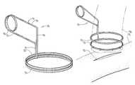
- FIG. 1is a perspective view of one embodiment of the present invention in which the clip is formed from a single length of wire and a resilient element in the form of a coil spring is formed into the handle of the clip.
- FIG. 2is a right side elevation view of the embodiment of FIG. 1 .
- FIG. 3is a top plan view of the embodiment of FIG. 1 .
- FIG. 4is a cross sectional detail of the relationships among the rings and the offset segments taken along the line 4 - 4 of FIG. 3 .
- FIG. 5is a top plan view of an embodiment of the present invention illustrating in phantom outline various sizes of substantially circular rings.
- FIG. 6is a top plan view of an embodiment of the present invention illustrating in phantom outline various sizes of wide elliptical rings.
- FIG. 7is a top plan view of an embodiment of the present invention illustrating in phantom outline various sizes of narrow elliptical rings.
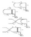
- FIG. 8is an elevation view of an alternative embodiment of the present invention in which a resilient element in the form of a segment of elastic material is disposed between the arms of the handle.
- FIG. 9is an elevation view of an alternative embodiment in which the clip is formed from a single length of wire with the two arms of the handle connected by a simple half circle.
- a resilient element in the form of a coil springis disposed between the arms of the handle.
- FIG. 10is an elevation view of an alternative embodiment in which the two arms of the handle are pivotally connected.
- FIG. 11is an elevation view of an alternative embodiment having pivotally connected arms as shown in FIG. 10 and a coil spring between the arms as shown in FIG. 9 .
- FIGS. 12-15are views of an embodiment of the present invention being employed to attach a graft vessel to a recipient vessel.
- FIGS. 12-14are perspective views showing the graft vessel sutured to the lower ring ( FIG. 12 ), the rings opened to allow the lower ring to be inserted into an arteriotomy in the recipient vessel ( FIG. 13 ) and the rings closed to complete the anastomosis ( FIG. 14 ).
- FIG. 15is a cross sectional detail along the line 15 - 15 of FIG. 14 .
- FIG. 16is an elevation view of two clips being employed to attach a graft vessel between a donor vessel and a recipient vessel.
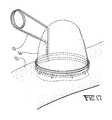
- FIG. 17is an elevation view of a clip being employed to attach an artificial aneurysm to a recipient vessel for surgical training purposes.
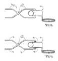
- FIGS. 18-19are elevation views of two embodiments of a clip applier.
- FIG. 20is a perspective view of the upper and lower rings with their respective inner surfaces roughened.
- FIGS. 21A-Eare elevation views of various embodiments of the handle.
- FIG. 22is an elevation view similar to that of FIG. 16 showing a graft with corrugations that allow it to be stretched to a desirable length between a donor vessel and a recipient vessel.
- the present inventionis a clip for use in end-to-side anastomoses, i.e., in connecting the end of a graft vessel to the side of a recipient vessel in different parts of a human or animal body.
- the clip 10comprises a handle 11 to which two rings, a lower ring 12 and an upper ring 13 , are attached.
- the two rings 12 , 13are closely juxtaposed when the clip 10 is closed.
- the handle 11may be similar to but smaller than the aneurysm clips known in the art, for example, the aneurysm clip disclosed in U.S. Pat. No. 4,765,335, the disclosure of which is incorporated herein in its entirety.
- the clip 10may be formed as shown in FIG. 1 from a single segment of material, such as by bending and forming a metal wire, or it may be formed in several pieces as will be described below.
- a preferred metal for constructing the clip 10is titanium or any bio-compatible metal. It will be desirable in some applications that the material from which the clip 10 is made is compatible with medical imaging devices, such as MRI's. In surgical training applications where the clip 10 is used with a cadaver model, the dip 10 may be made of plastic or the like.
- the handle 11may additionally incorporate means to urge the two rings 12 , 13 together by, for example, a resilient element such as a spring.
- the clip 10may itself be made of a resilient material, such as an elastic metal, that may also incorporate a resilient element such as a coil spring.
- the handle 11comprises a first arm 14 and a second arm 15 .
- the first arm 14is connected by a first offset segment 16 to the lower ring 12 .
- the first offset segment 16is disposed to pass to the inside of the upper ring 13 .
- the first offset segment 16may in one embodiment be substantially perpendicular to said first arm 14 and to said lower ring 12 .
- the second arm 15is connected by a second offset segment 17 to the upper ring 13 .
- the second offset segment 17may in one embodiment be substantially perpendicular to said second arm 15 and to said upper ring 13 . In other embodiments, the offset may be obtained by various combinations of straight and curved segments as desirable for various applications. Offsetting the main axis of the handle 11 from the plane containing the rings 12 , 13 allows the lower ring 12 to be placed into an arteriotomy of a recipient vessel as described below while maintaining the handle 11 spaced apart from the recipient vessel for ease of manipulation of the handle 11 .
- the two arms 14 , 15are connected by an integral coil spring 18 disposed so as to bias the two arms 14 , 15 apart and therefore to bias the two rings 12 , 13 together.
- FIGS. 1-4may be formed integrally from a single segment of resilient material, such as a metal wire.
- the clip applier 20may comprise a pair of members 21 , 22 pivotally connected about a hinge joint 23 .
- Each of said members 21 , 22comprises a jaw 25 , 24 respectively, disposed anteriorly of said hinge joint 23 and a grip 26 , 27 respectively, disposed posteriorly of said hinge joint 23 so that when the grips 26 , 27 are manually closed, the jaws 25 , 24 may be positioned to close onto the handles 14 , 15 to urge the rings 13 , 12 apart.
- the jaws 25 , 24may be curved as shown in FIG. 18 or, as shown in FIG. 19 , the jaws 25 , 24 may optionally be provided with buttons 28 on the interior faces of the jaws 25 , 24 to act as low friction pivot points between the jaws 25 , 24 and the arms 31 , 32 .
- the clip 30is made with two pivotal arms 31 , 32 which are pivotally connected at a pivot point 33 .
- the first pivotal arm 31is connected to the first offset segment 16 and thence to the lower ring 12 .
- the second pivotal arm 32is connected to the second offset segment 17 and thence to the upper ring 13 .
- FIGS. 8 and 10illustrate an alternative embodiment in which the resilient element is a segment of resilient material 34 disposed between the arms 14 , 15 or 31 , 32 .
- the resilient elementis a separate coil spring 35 disposed between the arms 31 , 32 or 36 , 37 .
- the arms 36 , 37are connected together by a resilient arc 38 .
- the clip 40 of FIG. 9may be formed integrally from a single segment of resilient material, such as a metal wire.
- FIG. 11illustrates an alternative embodiment having pivotally connected arms 31 , 32 as shown in FIG. 10 and a separate coil spring 35 between the arms 31 , 32 as shown in FIG. 9 .
- the handle 11may be of different shapes depending on the various applications of the clip 10 .
- the handle 11may include various combinations of straight and curved segments to accommodate various applications.
- the handle 11includes a straight segment 71 disposed substantially parallel to the plane of the rings 13 , 12 and operatively connected to the offset segments 16 , 17 by an oblique downwardly angled straight segment 71 .
- FIG. 21Bshows an alternative embodiment of the handle 11 having a straight segment 73 disposed substantially perpendicular to the plane of the rings 13 , 12 and connected first to a concavely curving segment 74 and thence to a straight segment 75 substantially parallel to the plane of the rings 13 , 12 .
- FIG. 21Cis an embodiment similar to that of FIG. 21A having an oblique straight segment 70 , but with a more sharply downwardly angled segment 76 . Oblique angles around 45° from the vertical are preferred.
- FIG. 21Dshows a handle 11 that comprises a curved segment 77 that is curved along substantially its entire length.
- FIG. 21Eshows a handle 11 that includes a substantially straight segment 78 that is disposed substantially parallel to the plane of the rings 12 , 13 as heretofore described in reference to FIGS. 21A and 21C .
- the straight segment 78is connected to a convexly curved segment 79 and thence to a second straight segment 80 .
- the embodiments of FIGS. 21A-Eare illustrative only and are not limiting to the full scope of the invention which may include various other shapes of handles to accommodate any applications for a vascular clip as would be apparent to one of skill in the art.
- the rings 13 , 12may also have different shapes and sizes to accommodate different kinds of anastomoses and different vessels of all sizes in all parts and cavities of the human or animal body, including without limitation the brain, thorax, abdomen, pelvis, neck and limbs.
- FIG. 5illustrates rings 13 that are substantially circular in varying sizes from large to small.
- FIG. 6illustrates rings 13 with an broad elliptical shape
- FIG. 7illustrates rings 13 with narrower elliptical shape.
- the lower ring 12is not shown in FIG. 5-7 , the two rings 12 , 13 are preferably substantially the same shape and size.
- the rings 12 , 13may have a maximum dimension (for example, a diameter in the case of a circular shape or a major axis in the case of an elliptical shape), which preferably is in the range of from around 2 mm up to around 2.5 cm, although the present invention is not limited to this size range.
- a maximum dimensionfor example, a diameter in the case of a circular shape or a major axis in the case of an elliptical shape
- the present inventionis not limited to this size range.
- the clip 10may be used to form an anastomosis by attaching a graft vessel 50 to a recipient vessel 51 .
- a graft vessel 50As shown in FIG. 12 , one end of the graft vessel 50 is inserted inside the two rings 12 , 13 and an edge of the open end of the graft vessel 50 is sutured to the lower ring 12 while the clip 10 is held open to allow such suturing.
- a hole 52(called an “arteriotomy”) is made in the recipient vessel 51 that is smaller than the diameter of the rings 12 , 13 . As shown in FIG.
- the lower ring 12 holding the open end of the graft vessel 50is inserted into the hole 52 in the recipient vessel 51 while the clip 10 is held open so that the edge of the hole 52 is positioned between the two rings 12 , 13 .
- the clip 10is then closed to catch the edge of the hole 52 in the recipient vessel 51 between the two rings 12 , 13 as they are closed tightly and the anastomosis is thereby completed.
- the graft vessel 50can be a vein or an artery (veins are preferred as having less thickness), either autologous or heterologous, or the graft vessel 50 can be made of a synthetic material. In the later case the graft vessel 50 may be attached to the lower ring 12 during the process of manufacturing the dip 10 .
- the lower surface of the upper ring 13 and the upper surface of the lower ring 12i.e., the surface of each ring 12 , 13 facing the other ring, may be provided with a rough surface 60 , 61 as shown in FIG. 20 .
- the surfacemay be roughened by any of various means known in the art, including parallel or crosshatched grooves.
- the inner surface of one ringmay be provided with spines (not shown) that fit into complementary holes (not shown) on the facing surface of the other rings.
- FIG. 16a clip 10 may be attached as described above to each end of a graft vessel 50 so that the graft vessel 50 may be connected between a donor vessel 53 and a recipient vessel 52 .
- FIG. 22shows an alternative version with a corrugated graft 90 that may be stretched to a desirable length between a donor vessel 53 and a recipient vessel 52 . This avoids placing any force on the graft between the donor and recipient vessels and allows various maneuvers while applying and attaching the clips to the vessels.
- a corrugated formis well known from vascular grafts made of TEFLON for major vessels such as the aorta.
- the graft 50 , 90may be made in different sizes, including different diameters corresponding to the sizes and diameters of the rings 12 , 13 .
- the graft 50 , 90may also be made in different lengths.
- an artificial aneurysm 54may be attached to the lower ring 12 of the clip 10 as described above so that the artificial aneurysm 54 may be connected to a recipient vessel 52 .
- This embodimentmay be particularly useful in surgical training and may be used in conjunction with a training model such as the cadaver model described in U.S. Pat. No. 6,790,043 to the same inventor as the present invention.
- the artificial aneurysm 54may be applied in the teaching of different treatment modalities, such as coiling and endovascular treatment.
- vascular anastomosesThe present invention has been described above with reference to vascular anastomoses. However, the invention is not limited to anastomoses with the vascular system, but may be applied to any anastomoses between tubular or hollow structures in the human or animal body. Any use of the term “vascular anastomosis” or “vascular anastomoses” is intended to refer to any anastomoses except when the context clearly limits the meaning to anastomoses between structures in the vascular system.
Landscapes
- Health & Medical Sciences (AREA)
- Life Sciences & Earth Sciences (AREA)
- Surgery (AREA)
- Heart & Thoracic Surgery (AREA)
- Engineering & Computer Science (AREA)
- Biomedical Technology (AREA)
- Nuclear Medicine, Radiotherapy & Molecular Imaging (AREA)
- Medical Informatics (AREA)
- Molecular Biology (AREA)
- Animal Behavior & Ethology (AREA)
- General Health & Medical Sciences (AREA)
- Public Health (AREA)
- Veterinary Medicine (AREA)
- Surgical Instruments (AREA)
Abstract
Description
Claims (15)
Priority Applications (2)
| Application Number | Priority Date | Filing Date | Title |
|---|---|---|---|
| US12/228,222US8328828B2 (en) | 2008-08-11 | 2008-08-11 | Device for performing an anastomosis |
| US12/583,423US20100036400A1 (en) | 2008-08-11 | 2009-08-20 | Vascular anastomosis device |
Applications Claiming Priority (1)
| Application Number | Priority Date | Filing Date | Title |
|---|---|---|---|
| US12/228,222US8328828B2 (en) | 2008-08-11 | 2008-08-11 | Device for performing an anastomosis |
Related Child Applications (1)
| Application Number | Title | Priority Date | Filing Date |
|---|---|---|---|
| US12/583,423Continuation-In-PartUS20100036400A1 (en) | 2008-08-11 | 2009-08-20 | Vascular anastomosis device |
Publications (2)
| Publication Number | Publication Date |
|---|---|
| US20100036398A1 US20100036398A1 (en) | 2010-02-11 |
| US8328828B2true US8328828B2 (en) | 2012-12-11 |
Family
ID=41653623
Family Applications (1)
| Application Number | Title | Priority Date | Filing Date |
|---|---|---|---|
| US12/228,222Expired - Fee RelatedUS8328828B2 (en) | 2008-08-11 | 2008-08-11 | Device for performing an anastomosis |
Country Status (1)
| Country | Link |
|---|---|
| US (1) | US8328828B2 (en) |
Families Citing this family (5)
| Publication number | Priority date | Publication date | Assignee | Title |
|---|---|---|---|---|
| CN102686170A (en)* | 2009-11-19 | 2012-09-19 | Amjb.V.公司 | Device for producing an anastomosis connection |
| JP2015506230A (en)* | 2012-01-12 | 2015-03-02 | コルファスコ メディカル ベスローテン フェンノートシャップCorvasco Medical B.V. | Blood vessel junction |
| DE102012211379A1 (en)* | 2012-06-29 | 2014-03-27 | Aesculap Ag | Surgical clip with inner spring |
| DE102012212629A1 (en)* | 2012-07-18 | 2014-02-20 | Aesculap Ag | Spring-supported clip |
| DE102017127290A1 (en) | 2017-11-20 | 2019-05-23 | Aesculap Ag | SURGICAL CLIP WITH BELLOW GUIDANCE SYSTEM |
Citations (38)
| Publication number | Priority date | Publication date | Assignee | Title |
|---|---|---|---|---|
| US306692A (en)* | 1884-10-14 | Clasp | ||
| US2627095A (en)* | 1949-07-25 | 1953-02-03 | Palmieri Jose Atilio | Wire spring clip |
| US4041931A (en)* | 1976-05-17 | 1977-08-16 | Elliott Donald P | Radiopaque anastomosis marker |
| US4765335A (en) | 1987-03-16 | 1988-08-23 | Intermar, Inc. | Aneurysm clip |
| US4771775A (en)* | 1984-04-10 | 1988-09-20 | Idea Research Investment Fund, Inc. | Anastomosis devices, kits and method |
| US4777949A (en)* | 1987-05-08 | 1988-10-18 | Metatech Corporation | Surgical clip for clamping small blood vessels in brain surgery and the like |
| US4787386A (en)* | 1984-04-10 | 1988-11-29 | Idea Research Investment Fund, Inc. | Anastomosis devices, and kits |
| US4961743A (en)* | 1989-01-03 | 1990-10-09 | Codman & Shurtleff, Inc. | Torsion spring |
| US5053045A (en)* | 1988-09-16 | 1991-10-01 | Schmidt Ferenc J | Surgical clip |
| US5059211A (en) | 1987-06-25 | 1991-10-22 | Duke University | Absorbable vascular stent |
| US5380290A (en) | 1992-04-16 | 1995-01-10 | Pfizer Hospital Products Group, Inc. | Body access device |
| US5443497A (en) | 1993-11-22 | 1995-08-22 | The Johns Hopkins University | Percutaneous prosthetic by-pass graft and method of use |
| US5653744A (en) | 1995-04-27 | 1997-08-05 | Khouri Biomedical Research, Inc. | Device and method for vascular anastomosis |
| US5843170A (en) | 1994-09-02 | 1998-12-01 | Ahn; Sam Seunghae | Apparatus and method for performing aneurysm repair |
| US6019788A (en) | 1996-11-08 | 2000-02-01 | Gore Enterprise Holdings, Inc. | Vascular shunt graft and junction for same |
| US6110188A (en) | 1998-03-09 | 2000-08-29 | Corvascular, Inc. | Anastomosis method |
| US6123682A (en) | 1996-08-13 | 2000-09-26 | Heartstent Corporation | Closed chest coronary bypass |
| WO2001015618A2 (en) | 1999-08-31 | 2001-03-08 | The Cleveland Clinic Foundation | Non-occlusive vascular bypass surgical methods and instruments |
| US6371965B2 (en) | 1995-02-24 | 2002-04-16 | Gifford, Iii Hanson S. | Devices and methods for performing a vascular anastomosis |
| US6402767B1 (en) | 1997-05-22 | 2002-06-11 | Kensey Nash Corporation | Anastomosis connection system and method of use |
| US6485513B1 (en) | 1999-10-08 | 2002-11-26 | The General Hospital Corporation | Percutaneous stent graft and method for vascular bypass |
| WO2002096298A1 (en) | 2001-05-31 | 2002-12-05 | Hb Medicals Corporation | Vascular anastomosis device |
| US6491707B2 (en) | 1997-06-28 | 2002-12-10 | Transvascular, Inc. | Transluminal methods and devices for closing, forming attachments to, and/or forming anastomotic junctions in, luminal anatomical structures |
| WO2002098303A1 (en) | 2001-06-07 | 2002-12-12 | Hb Medicals Corporation | Vascular anastomosis device |
| WO2003007843A2 (en) | 2001-07-17 | 2003-01-30 | Universite Joseph Fourier | Vascular anastomosis device |
| US6596003B1 (en) | 2000-06-28 | 2003-07-22 | Genzyme Corporation | Vascular anastomosis device |
| US6652545B2 (en)* | 1999-03-01 | 2003-11-25 | Surgicon, Inc. | Ligation clip and clip applier |
| US6709442B2 (en) | 2000-09-01 | 2004-03-23 | Onux Medical, Inc. | Vascular bypass grafting instrument and method |
| US6743243B1 (en) | 1998-03-20 | 2004-06-01 | Sumit Roy | Support device for endoscopic suturless anastomosis |
| US20040215220A1 (en) | 2003-04-24 | 2004-10-28 | Dolan Mark J. | Anastomotic stent, apparatus and methods of use thereof |
| US20050182483A1 (en) | 2004-02-11 | 2005-08-18 | Cook Incorporated | Percutaneously placed prosthesis with thromboresistant valve portion |
| US6960219B2 (en) | 1999-03-09 | 2005-11-01 | St. Jude Medical Atg, Inc. | Medical grafting methods and apparatus |
| US7141060B1 (en) | 2000-01-20 | 2006-11-28 | Katharina Metz | Instrument for inserting a prosthesis tube connection |
| US20060282106A1 (en)* | 2000-04-29 | 2006-12-14 | Ventrica, Inc. A Delaware Corporation | Devices and methods for forming magnetic anastomoses between vessels |
| US7220268B2 (en) | 1999-04-16 | 2007-05-22 | Integrated Vascular Interventional Technologies, L.C. (Ivit Lc) | Methods for anastomosis of a graft vessel to a side of a receiving vessel |
| US20080045985A1 (en)* | 2006-06-21 | 2008-02-21 | The Board Of Trustees Of The Leland Stanford Junior University | Compositions and methods for joining non-conjoined lumens |
| US20080195125A1 (en)* | 2007-02-12 | 2008-08-14 | Hoffman Grant T | Device for heart bypass surgery and anastomosis |
| US20100122698A1 (en) | 2008-11-19 | 2010-05-20 | The Nemours Foundation | Neonatal airway stent |
- 2008
- 2008-08-11USUS12/228,222patent/US8328828B2/ennot_activeExpired - Fee Related
Patent Citations (39)
| Publication number | Priority date | Publication date | Assignee | Title |
|---|---|---|---|---|
| US306692A (en)* | 1884-10-14 | Clasp | ||
| US2627095A (en)* | 1949-07-25 | 1953-02-03 | Palmieri Jose Atilio | Wire spring clip |
| US4041931A (en)* | 1976-05-17 | 1977-08-16 | Elliott Donald P | Radiopaque anastomosis marker |
| US4787386A (en)* | 1984-04-10 | 1988-11-29 | Idea Research Investment Fund, Inc. | Anastomosis devices, and kits |
| US4771775A (en)* | 1984-04-10 | 1988-09-20 | Idea Research Investment Fund, Inc. | Anastomosis devices, kits and method |
| US4765335A (en) | 1987-03-16 | 1988-08-23 | Intermar, Inc. | Aneurysm clip |
| US4777949A (en)* | 1987-05-08 | 1988-10-18 | Metatech Corporation | Surgical clip for clamping small blood vessels in brain surgery and the like |
| US5059211A (en) | 1987-06-25 | 1991-10-22 | Duke University | Absorbable vascular stent |
| US5053045A (en)* | 1988-09-16 | 1991-10-01 | Schmidt Ferenc J | Surgical clip |
| US4961743A (en)* | 1989-01-03 | 1990-10-09 | Codman & Shurtleff, Inc. | Torsion spring |
| US5380290A (en) | 1992-04-16 | 1995-01-10 | Pfizer Hospital Products Group, Inc. | Body access device |
| US5443497A (en) | 1993-11-22 | 1995-08-22 | The Johns Hopkins University | Percutaneous prosthetic by-pass graft and method of use |
| US5843170A (en) | 1994-09-02 | 1998-12-01 | Ahn; Sam Seunghae | Apparatus and method for performing aneurysm repair |
| US6371965B2 (en) | 1995-02-24 | 2002-04-16 | Gifford, Iii Hanson S. | Devices and methods for performing a vascular anastomosis |
| US20050149077A1 (en)* | 1995-02-24 | 2005-07-07 | Gifford Hanson S.Iii | Devices and methods for performing a vascular anastomosis |
| US5653744A (en) | 1995-04-27 | 1997-08-05 | Khouri Biomedical Research, Inc. | Device and method for vascular anastomosis |
| US6123682A (en) | 1996-08-13 | 2000-09-26 | Heartstent Corporation | Closed chest coronary bypass |
| US6019788A (en) | 1996-11-08 | 2000-02-01 | Gore Enterprise Holdings, Inc. | Vascular shunt graft and junction for same |
| US6402767B1 (en) | 1997-05-22 | 2002-06-11 | Kensey Nash Corporation | Anastomosis connection system and method of use |
| US6491707B2 (en) | 1997-06-28 | 2002-12-10 | Transvascular, Inc. | Transluminal methods and devices for closing, forming attachments to, and/or forming anastomotic junctions in, luminal anatomical structures |
| US6110188A (en) | 1998-03-09 | 2000-08-29 | Corvascular, Inc. | Anastomosis method |
| US6743243B1 (en) | 1998-03-20 | 2004-06-01 | Sumit Roy | Support device for endoscopic suturless anastomosis |
| US6652545B2 (en)* | 1999-03-01 | 2003-11-25 | Surgicon, Inc. | Ligation clip and clip applier |
| US6960219B2 (en) | 1999-03-09 | 2005-11-01 | St. Jude Medical Atg, Inc. | Medical grafting methods and apparatus |
| US7220268B2 (en) | 1999-04-16 | 2007-05-22 | Integrated Vascular Interventional Technologies, L.C. (Ivit Lc) | Methods for anastomosis of a graft vessel to a side of a receiving vessel |
| WO2001015618A2 (en) | 1999-08-31 | 2001-03-08 | The Cleveland Clinic Foundation | Non-occlusive vascular bypass surgical methods and instruments |
| US6485513B1 (en) | 1999-10-08 | 2002-11-26 | The General Hospital Corporation | Percutaneous stent graft and method for vascular bypass |
| US7141060B1 (en) | 2000-01-20 | 2006-11-28 | Katharina Metz | Instrument for inserting a prosthesis tube connection |
| US20060282106A1 (en)* | 2000-04-29 | 2006-12-14 | Ventrica, Inc. A Delaware Corporation | Devices and methods for forming magnetic anastomoses between vessels |
| US6596003B1 (en) | 2000-06-28 | 2003-07-22 | Genzyme Corporation | Vascular anastomosis device |
| US6709442B2 (en) | 2000-09-01 | 2004-03-23 | Onux Medical, Inc. | Vascular bypass grafting instrument and method |
| WO2002096298A1 (en) | 2001-05-31 | 2002-12-05 | Hb Medicals Corporation | Vascular anastomosis device |
| WO2002098303A1 (en) | 2001-06-07 | 2002-12-12 | Hb Medicals Corporation | Vascular anastomosis device |
| WO2003007843A2 (en) | 2001-07-17 | 2003-01-30 | Universite Joseph Fourier | Vascular anastomosis device |
| US20040215220A1 (en) | 2003-04-24 | 2004-10-28 | Dolan Mark J. | Anastomotic stent, apparatus and methods of use thereof |
| US20050182483A1 (en) | 2004-02-11 | 2005-08-18 | Cook Incorporated | Percutaneously placed prosthesis with thromboresistant valve portion |
| US20080045985A1 (en)* | 2006-06-21 | 2008-02-21 | The Board Of Trustees Of The Leland Stanford Junior University | Compositions and methods for joining non-conjoined lumens |
| US20080195125A1 (en)* | 2007-02-12 | 2008-08-14 | Hoffman Grant T | Device for heart bypass surgery and anastomosis |
| US20100122698A1 (en) | 2008-11-19 | 2010-05-20 | The Nemours Foundation | Neonatal airway stent |
Non-Patent Citations (1)
| Title |
|---|
| Office Action, U.S. Appl. No. 12/583,423, Mar. 12, 2012. |
Also Published As
| Publication number | Publication date |
|---|---|
| US20100036398A1 (en) | 2010-02-11 |
Similar Documents
| Publication | Publication Date | Title |
|---|---|---|
| US8328828B2 (en) | Device for performing an anastomosis | |
| CA1251113A (en) | Surgical microclip | |
| KR102622541B1 (en) | Eyelash applicators, magnetic artificial eyelashes, and methods for using the same | |
| US5030224A (en) | Coronary artery retraction clip | |
| US4733664A (en) | Surgical clip, applier, and method | |
| US6176864B1 (en) | Anastomosis device and method | |
| US4809695A (en) | Suturing assembly and method | |
| US5554162A (en) | Method and device for surgically joining luminal structures | |
| US4979954A (en) | Staple suturing method | |
| US20120271336A1 (en) | System and method for measuring a vessel in a vascular environment | |
| US20070167898A1 (en) | Methods and devices for tensioning a wrap around a blood vessel | |
| US20020116018A1 (en) | Anastomosis system and methods for use | |
| JPH10509615A (en) | Surgical clip having a longitudinal opening through which the tissue to be clamped protrudes | |
| US20190126017A1 (en) | Subcutaneous vascular assemblies for improving blood flow and related devices and methods | |
| JP2002512077A (en) | Two-piece artificial heart valve | |
| CA2556912A1 (en) | Internal prosthesis for reconstruction of cardiac geometry | |
| JP2018508280A (en) | Surgical staple having two movable arms connected by a lateral connection region | |
| US20100036400A1 (en) | Vascular anastomosis device | |
| US20030065344A1 (en) | Method and device for creating microvascular anastomoses | |
| JP2011524188A (en) | Anastomosis instrument | |
| JP2006006648A (en) | Blood vessel connecting tool and blood vessel connecting device | |
| US20050182430A1 (en) | Anastomosis device and method | |
| KR20250049292A (en) | Device for anastomosing severed blood vessels | |
| US12357310B2 (en) | Device and method for connecting tubular structures | |
| US20170333031A1 (en) | Suture holding sleeve for laparoscopic instruments |
Legal Events
| Date | Code | Title | Description |
|---|---|---|---|
| AS | Assignment | Owner name:BOARD OF TRUSTEES OF THE UNIVERSITY OF ARKANSAS,AR Free format text:ASSIGNMENT OF ASSIGNORS INTEREST;ASSIGNOR:ABOUD, EMAD T.;REEL/FRAME:021432/0026 Effective date:20080716 Owner name:BOARD OF TRUSTEES OF THE UNIVERSITY OF ARKANSAS, A Free format text:ASSIGNMENT OF ASSIGNORS INTEREST;ASSIGNOR:ABOUD, EMAD T.;REEL/FRAME:021432/0026 Effective date:20080716 | |
| STCF | Information on status: patent grant | Free format text:PATENTED CASE | |
| FEPP | Fee payment procedure | Free format text:PATENT HOLDER CLAIMS MICRO ENTITY STATUS, ENTITY STATUS SET TO MICRO (ORIGINAL EVENT CODE: STOM); ENTITY STATUS OF PATENT OWNER: MICROENTITY | |
| FPAY | Fee payment | Year of fee payment:4 | |
| AS | Assignment | Owner name:BIOVENTURES, LLC, ARKANSAS Free format text:ASSIGNMENT OF ASSIGNORS INTEREST;ASSIGNOR:BOARD OF TRUSTEES OF THE UNIVERSITY OF ARKANSAS;REEL/FRAME:041831/0308 Effective date:20170222 | |
| FEPP | Fee payment procedure | Free format text:MAINTENANCE FEE REMINDER MAILED (ORIGINAL EVENT CODE: REM.); ENTITY STATUS OF PATENT OWNER: MICROENTITY | |
| LAPS | Lapse for failure to pay maintenance fees | Free format text:PATENT EXPIRED FOR FAILURE TO PAY MAINTENANCE FEES (ORIGINAL EVENT CODE: EXP.); ENTITY STATUS OF PATENT OWNER: MICROENTITY | |
| STCH | Information on status: patent discontinuation | Free format text:PATENT EXPIRED DUE TO NONPAYMENT OF MAINTENANCE FEES UNDER 37 CFR 1.362 | |
| FP | Lapsed due to failure to pay maintenance fee | Effective date:20201211 |