US8328817B2 - Multiplanar taper lock screw and lock indicator gauge - Google Patents
Multiplanar taper lock screw and lock indicator gaugeDownload PDFInfo
- Publication number
- US8328817B2 US8328817B2US12/612,960US61296009AUS8328817B2US 8328817 B2US8328817 B2US 8328817B2US 61296009 AUS61296009 AUS 61296009AUS 8328817 B2US8328817 B2US 8328817B2
- Authority
- US
- United States
- Prior art keywords
- housing
- bone screw
- plunger
- lock
- indicator gauge
- Prior art date
- Legal status (The legal status is an assumption and is not a legal conclusion. Google has not performed a legal analysis and makes no representation as to the accuracy of the status listed.)
- Expired - Fee Related, expires
Links
Images


Classifications
- A—HUMAN NECESSITIES
- A61—MEDICAL OR VETERINARY SCIENCE; HYGIENE
- A61B—DIAGNOSIS; SURGERY; IDENTIFICATION
- A61B17/00—Surgical instruments, devices or methods
- A61B17/56—Surgical instruments or methods for treatment of bones or joints; Devices specially adapted therefor
- A61B17/58—Surgical instruments or methods for treatment of bones or joints; Devices specially adapted therefor for osteosynthesis, e.g. bone plates, screws or setting implements
- A61B17/68—Internal fixation devices, including fasteners and spinal fixators, even if a part thereof projects from the skin
- A61B17/70—Spinal positioners or stabilisers, e.g. stabilisers comprising fluid filler in an implant
- A61B17/7001—Screws or hooks combined with longitudinal elements which do not contact vertebrae
- A61B17/7032—Screws or hooks with U-shaped head or back through which longitudinal rods pass
- A—HUMAN NECESSITIES
- A61—MEDICAL OR VETERINARY SCIENCE; HYGIENE
- A61B—DIAGNOSIS; SURGERY; IDENTIFICATION
- A61B17/00—Surgical instruments, devices or methods
- A61B17/56—Surgical instruments or methods for treatment of bones or joints; Devices specially adapted therefor
- A61B17/58—Surgical instruments or methods for treatment of bones or joints; Devices specially adapted therefor for osteosynthesis, e.g. bone plates, screws or setting implements
- A61B17/68—Internal fixation devices, including fasteners and spinal fixators, even if a part thereof projects from the skin
- A61B17/70—Spinal positioners or stabilisers, e.g. stabilisers comprising fluid filler in an implant
- A61B17/7001—Screws or hooks combined with longitudinal elements which do not contact vertebrae
- A61B17/7035—Screws or hooks, wherein a rod-clamping part and a bone-anchoring part can pivot relative to each other
- A—HUMAN NECESSITIES
- A61—MEDICAL OR VETERINARY SCIENCE; HYGIENE
- A61B—DIAGNOSIS; SURGERY; IDENTIFICATION
- A61B17/00—Surgical instruments, devices or methods
- A61B17/56—Surgical instruments or methods for treatment of bones or joints; Devices specially adapted therefor
- A61B17/58—Surgical instruments or methods for treatment of bones or joints; Devices specially adapted therefor for osteosynthesis, e.g. bone plates, screws or setting implements
- A61B17/68—Internal fixation devices, including fasteners and spinal fixators, even if a part thereof projects from the skin
- A61B17/70—Spinal positioners or stabilisers, e.g. stabilisers comprising fluid filler in an implant
- A61B17/7074—Tools specially adapted for spinal fixation operations other than for bone removal or filler handling
- A61B17/7076—Tools specially adapted for spinal fixation operations other than for bone removal or filler handling for driving, positioning or assembling spinal clamps or bone anchors specially adapted for spinal fixation
Definitions
- the present disclosurerelates to gauges that indicate the state or condition of a bone fixation device, e.g., whether the bone fixation device is locked or unlocked. More particularly the present disclosure relates to a lock indicator gauge to indicate whether a bone screw, e.g., a multiplanar taper lock screw for securing a spinal rod to a vertebra, is in a locked or in an unlocked state.
- a bone screwe.g., a multiplanar taper lock screw for securing a spinal rod to a vertebra
- Surgical spinal correction proceduresinvolve the placement of a plurality of bone pins, anchors, cables, hooks, or screws placed in adjacent vertebrae and using spinal rods to maintain a predetermined spatial relationship between the vertebrae.
- such devicesare permanently implanted in the subject. However, in other cases, the devices may be subsequently removed when no longer needed. Moreover, it is common that devices that were intended to be permanently implanted may require subsequent procedures or revisions as the patient's condition necessitates. For this reason, it is desirable that an implanted device be readily locked and unlocked as desired by a surgeon. Determination of whether an implanted device is locked or unlocked may not be readily apparent by merely visually inspecting the device.
- a lock indicator gaugeadapted and configured to provide an indication of whether a bone screw construct is in a locked or an unlocked position.
- the lock indicator gaugeis adapted and configured to provide an indication of the relative position of an inner and an outer housing of the bone screw construct. Since the relative position of the inner and outer housings in the locked and unlocked states or conditions is known, an indication of the relative position of the inner and outer housings provides for determination of the state of the bone screw construct.
- the lock indicator gaugeincludes a housing that includes a proximal end, a distal end, and a first longitudinal axis.
- a plungeris longitudinally disposed within the housing, along the first longitudinal axis.
- the distal end of the housingis adapted to receive a proximal end of a bone screw construct having an inner housing, e.g., collet, and an outer housing, e.g., coupling.
- the inner and outer housingshare a common second longitudinal axis that is coaxial with the first longitudinal axis when the lock indicator gauge engages the proximal end of the bone screw construct.
- Each of the inner and outer housingshas a position along the second longitudinal axis that may be equal or different.
- Placement of the lock indicator gauge atop the bone screw constructresults in displacement or translation of the plunger proximally through the housing by a distance corresponding to the difference in position of the outer and inner housings of the bone screw construct along the second longitudinal axis.
- An indicatorprovides indication of the position of the plunger relative to the housing.
- the distal end of the plungerfunctions as an indicator by extending through a lumen at the proximal end of the housing by a distance corresponding to the distance defined by the relative positions of the inner and outer housings of the bone screw construct.
- the plungermay include at least one visual cue along a longitudinal surface of the plunger, i.e., the shaft of the plunger.
- the at least one visual cuemay be, but is not limited to, a mark, a groove, a color, or a word.
- the lock indicator gaugemay provide a visual, tactile, and/or audible indication of the position of the plunger relative to the housing of the lock indicator gauge.
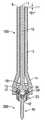
- FIG. 1Ais a front view of a bone screw construct shown in a first condition
- FIG. 1Bis a front view of the bone screw construct of FIG. 1A shown in a second condition
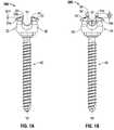
- FIG. 2is a top perspective view of an outer housing or coupling
- FIG. 3is a top perspective view of an inner housing or collet
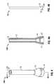
- FIG. 4is an isometric view of a lock indicator gauge including a housing and a plunger
- FIG. 4Ais a cross-sectional view of the housing of FIG. 4 taken along section line 4 A- 4 A;
- FIG. 4Bis a front view of the plunger of FIG. 4 ;
- FIG. 5Ais a front view of the lock indicator device of FIG. 4 shown in a first condition
- FIG. 5Bis a front view of the lock indicator device of FIG. 4 shown in a second condition
- FIG. 6is a front view of the lock indicator gauge of FIG. 4 shown relative to the bone screw construct of FIG. 1A ;
- FIG. 7is a front view of the lock indicator gauge of FIG. 4 coupled to the bone screw construct of FIG. 1A shown in a first condition;
- FIG. 7Ais cross-sectional view of the lock indicator gauge of FIG. 4 coupled to the bone screw construct of FIG. 1A as shown in FIG. 7A , taken along section line 7 A- 7 A;
- FIG. 8is a front perspective view of the lock indicator gauge of FIG. 4 coupled to the bone screw construct of FIG. 1A shown in a second condition;
- FIG. 8Ais a cross-sectional view of the lock indicator gauge of FIG. 4 coupled to the bone screw construct of FIG. 1A , as shown in FIG. 8 , taken along section line 8 A- 8 A.
- proximalwill refer to the end of a gauge or system that is closest to the operator
- distalwill refer to end of the gauge or system that is farthest from the operator
- cephaladis used in this application to indicate a direction toward a patient's head
- the term “caudad”indicates a direction toward the patient's feet.
- the term “medial”indicates a direction toward a side of the body of the patient, i.e., away from the middle of the body of the patient.
- anteriorindicates a direction toward the patient's back
- anteriorindicates a direction toward the patient's front
- terms such as front, rear, upper, lower, top, bottom, and similar directional termsare used simply for convenience of description and are not intended to limit the disclosure coupled hereto.
- the bone screw construct 200includes an outer housing or coupling 20 ( FIG. 2 ), an inner housing or collet 30 ( FIG. 3 ), and a bone screw 40 .
- the bone screw 40is a multi-planar taper lock screw and includes a screwhead 42 ( FIG. 7A ) that is rotatable and pivotable relative to coupling 20 and collet 30 , thereby allowing the screw 40 to be positioned in a plurality of orientations relative to the coupling 20 and the collet 30 .
- the bone screw construct 200is operatively connectable to a rod (not shown). The ability to position the bone screw 40 in a plurality of orientations relative to the coupling 20 and the collet 30 facilitates the operative coupling of the rod to vertebrae that are not coplanar or other bone structures that have a discontinuity.
- the coupling 20includes an annular body portion 26 including an opening 28 that extends axially therethrough. Additionally, the coupling 20 includes a plurality of fingers 24 that are located in opposing regions of the coupling 20 and define a saddle 22 having a generally U-shaped configuration. The U-shaped saddle 22 is configured and dimensioned for receiving the rod.
- the collet 30shown in FIG. 3 , is configured and adapted to be placed within coupling 20 .
- Collet 30has a generally cylindrical body portion 36 including an opening 37 extending axially therethrough.
- a pair of upstanding wings 34defines a saddle 32 having a generally U-shaped configuration.
- the saddle 32is configured and dimensioned for receiving a rod (not shown).
- the body portion 36includes a slot 35 that extends from the nadir of the saddle 32 towards the bottom of the body portion 36 and essentially bisects the body portion 36 along a central axis, and defines left and right sections of the body portion.
- the slot 35does not extend all the way through the body portion. Although less desirable, such a full slot could be used.
- a plurality of grooves 31 and notches 33may facilitate flexure of the collet 30 in response to compressive and tensile forces.
- This arrangementpermits each of the wings 34 to flex towards and away from each other.
- the dimensions of the saddle 32vary according to the flexure of the wings 34 . As the wings 34 are moved closer to each other, the saddle 32 decreases in size and when the wings 34 are moved away from each other, the saddle 32 increases in size. Allowing the saddle 32 to vary in size permits the collet 30 to accommodate rods having different outside diameters. Compression of the wings 34 towards each other increasingly engages the outer surface of the rod when the rod is located in the saddle 32 , thereby frictionally securing the rod in a desired position.
- Collet 30is retained within the coupling 20 .
- Collet 30 and coupling 20are slidable relative to one another, as seen in FIGS. 1A and 1B .
- the bone screw construct 200is in a locked position, as shown in FIG. 1A , the collet 30 is substantially within coupling 20 , the collet 30 is compressed such that the dimensions of saddle 32 are sized to frictionally secure a rod placed within saddle 32 .
- the relative position between a proximal surface 24 a of finger 24 of the coupling 20 and a proximal surface 34 a of wing 34 of the collet 30 along an axis “A”is equal to a distance “D 1 ”.
- the relative position between a proximal surface 24 a of finger 24 of the coupling 20 and a proximal surface 34 a of wing 34 of the collet 30 along an axis “A”is equal to a distance “D 2 ”.
- Distance “D 2 ”is greater than distance “D 1 ” and indicates that the collet 30 is not substantially positioned within the coupling 20 .
- the collet 30is not sufficiently compressed to secure rod when placed within saddle 32 , and the bone screw construct is in the unlocked position.
- a lock indicator gauge 100is configured and adapted to interact with the bone screw construct 200 to provide an indication of whether the bone screw construct 200 is in a locked or in an unlocked state or condition.
- the lock indicator gauge 100may provide a visual, tactile, and/or audible indication of the condition of the bone screw construct 200 . While the function of the lock indicator gauge 100 will be described herein with reference to the bone screw construct 200 , it is to be understood that the lock indicator gauge 100 may be used with a variety of bone screw constructs. Examples of some suitable bone screw constructs are found in International Patent Application PCT/US08/80682, the entire contents of which are incorporated by reference.
- the lock indicator gauge 100includes a housing 12 , a receptacle 14 , and an indicator button 11 disposed a proximal end of a plunger 10 that is longitudinally disposed within housing 12 ( FIG. 4B ).
- the housingincludes a through hole or lumen 13 that extends the length of the housing 12 and a receptacle 14 that is adapted and configured to receive a proximal end of the bone screw construct 200 therein.
- the receptacle 14includes contacting members 17 that are configured and adapted to position the housing 12 coaxially with a longitudinal axis “A” ( FIGS.
- the plunger 10shown in FIG. 4B , includes the indicator button 11 at the proximal end of the plunger and distal end 18 that includes contacting members 15 .
- a cutout 19 at the distal end 18 of the plunger 10may be included to inhibit the rod from interfering with determining the condition of the bone screw construct 200 .
- the indicator button 11 at the distal end of the plunger 10has a retracted position ( FIGS. 4 , 5 A, 7 , 7 A) and an actuated or extended position ( FIGS. 5B , 8 , 8 A).
- the indicator button 11may also be in an intermediate position between that of the actuated and extended positions to reflect a partially locked condition of the bone screw construct 200 . Placement of the lock indicator gauge atop the bone screw construct 200 results in the indicator button 11 being in one of the actuated, the retracted, or the intermediate positions.
- An actuated position of the indicator button 11corresponds to the unlocked state of the bone screw construct ( FIG.
- a retracted position of the indicator button 11corresponds to the locked state of the bone screw construct ( FIG. 1A ).
- the indicator button 11may be substantially flush with a top surface 9 of housing 12 , as shown in FIG. 4 .
- a retracted positionmay be indicated when a top surface of the indicator button 11 is partially raised above top surface 9 of the housing 12 by distance “D 1 ”.
- the bone screw construct 200may also be partially locked. In the event the bone screw construct 200 is partially locked, the plunger 10 will be displaced by a distance between that defined by distance “D 1 ” and distance “D 2 ”.
- a visual cuee.g., a color or a mark
- Marks or visual cuese.g., lines, grooves, words, lights, and/or colors
- visual cuesmay be longitudinally disposed along a length of the plunger 10 and may be exposed or activated as the indicator button 11 is extended from within housing 12 .
- the visual cues or marksmay be arranged in intervals to provide measurements as to the extent to which the plunger is extended from within housing 12 .
- the visual cues or marks displayedis dependent upon the degree of displacement of the plunger 10 , thereby providing indication of intermediate states in which the bone screw construct 200 may have between a fully locked state and a fully unlocked state, i.e., a partially locked state.
- the visual cuesmay be disposed at the proximal end of the plunger 10 , e.g., a colored light such as a light emitting diode (LED) disposed at the proximal end of the lock indicator gauge 100 .
- the plunger 10need not protrude from within housing 12 through a lumen 13 to provide an indication of the position of the plunger within the housing 12 .
- the housing 12may be partially or entirely transparent, thereby permitting visual inspection of the position of the plunger 10 .
- the lock indicator gauge 100is brought into proximity with the bone screw construct 200 , aligning the lock indicator gauge 100 and bone screw construct 200 along common axis “A”. Placement of the lock indicator gauge 100 atop the bone screw construct 200 engages contacting members 17 of the receptacle 14 with the fingers 24 of the coupling 20 . As the contacting members 17 rest atop fingers 24 of the coupling, the plunger 10 is urged proximally through lumen 13 as contacting members 15 of the plunger engage wings 34 of the collet 30 . The plunger 10 is translated through the housing 12 by a distance defined between proximal surfaces 24 a , 34 a of the coupling 20 and collet 30 , respectively.
- a locked conditionis indicated as shown in FIGS. 7 and 7A by the proximal translation of the plunger 10 and position of the top surface of the indicator button 11 above the top surface 9 of housing 12 by distance “D 1 ”.
- an unlocked conditionis indicated as shown in FIGS. 8 and 8A , by the proximal translation of the plunger 10 and position of the top surface of the indicator button 11 above the top surface 9 of the housing by distance “D 2 ”.
- translation of the plunger 10 through the housing 12 of the lock indicator gauge 100may result in an audible indication, e.g., a click.
- translation of the plunger 10 through the housing 12may result in a tactile indication, e.g., a user may feel a vibration.
Landscapes
- Health & Medical Sciences (AREA)
- Orthopedic Medicine & Surgery (AREA)
- Neurology (AREA)
- Life Sciences & Earth Sciences (AREA)
- Surgery (AREA)
- Heart & Thoracic Surgery (AREA)
- Engineering & Computer Science (AREA)
- Biomedical Technology (AREA)
- Nuclear Medicine, Radiotherapy & Molecular Imaging (AREA)
- Medical Informatics (AREA)
- Molecular Biology (AREA)
- Animal Behavior & Ethology (AREA)
- General Health & Medical Sciences (AREA)
- Public Health (AREA)
- Veterinary Medicine (AREA)
- Surgical Instruments (AREA)
Abstract
Description
Claims (12)
Priority Applications (1)
| Application Number | Priority Date | Filing Date | Title |
|---|---|---|---|
| US12/612,960US8328817B2 (en) | 2008-11-05 | 2009-11-05 | Multiplanar taper lock screw and lock indicator gauge |
Applications Claiming Priority (2)
| Application Number | Priority Date | Filing Date | Title |
|---|---|---|---|
| US19839308P | 2008-11-05 | 2008-11-05 | |
| US12/612,960US8328817B2 (en) | 2008-11-05 | 2009-11-05 | Multiplanar taper lock screw and lock indicator gauge |
Publications (2)
| Publication Number | Publication Date |
|---|---|
| US20100114108A1 US20100114108A1 (en) | 2010-05-06 |
| US8328817B2true US8328817B2 (en) | 2012-12-11 |
Family
ID=42132333
Family Applications (1)
| Application Number | Title | Priority Date | Filing Date |
|---|---|---|---|
| US12/612,960Expired - Fee RelatedUS8328817B2 (en) | 2008-11-05 | 2009-11-05 | Multiplanar taper lock screw and lock indicator gauge |
Country Status (1)
| Country | Link |
|---|---|
| US (1) | US8328817B2 (en) |
Cited By (26)
| Publication number | Priority date | Publication date | Assignee | Title |
|---|---|---|---|---|
| US20110276098A1 (en)* | 2010-05-05 | 2011-11-10 | Lutz Biedermann | Receiving part for receiving a rod for coupling the rod to a bone anchoring element, bone anchoring device, method and tool for assembling the same |
| US20120179209A1 (en)* | 2010-12-10 | 2012-07-12 | Lutz Biedermann | Receiving part for receiving a rod for coupling the rod to a bone anchoring element and a bone anchoring device |
| US20130103039A1 (en)* | 2011-10-25 | 2013-04-25 | Warsaw Orthopedic, Inc. | Bone screw extender reattachment system and methods |
| US20140277137A1 (en)* | 2013-03-14 | 2014-09-18 | DePuy Synthes Products, LLC | Devices and methods for monoaxial screw conversion |
| US20140336709A1 (en)* | 2013-03-13 | 2014-11-13 | Baxano Surgical, Inc. | Multi-threaded pedicle screw system |
| US8940024B2 (en) | 2007-07-31 | 2015-01-27 | Biedermann Technologies Gmbh & Co. Kg | Bone anchoring device |
| US20150190183A1 (en)* | 2012-07-19 | 2015-07-09 | Safe Orthopaedics | Device for Guiding a Surgical Instrument Into Position On a Bone-Anchor Element Including A Means For Realigning a Link Rod With the Anchor Element, and Related System of Surgical Instruments |
| CN104905861A (en)* | 2014-03-14 | 2015-09-16 | 比德尔曼技术有限责任两合公司 | Device for placing a receiving part onto a head of a bone anchoring element |
| US10299843B2 (en)* | 2017-06-02 | 2019-05-28 | Bret Michael Berry | Tulip head and collet for a poly axial screw |
| US10722276B2 (en) | 2013-03-14 | 2020-07-28 | K2M, Inc. | Taper lock hook |
| US11213323B2 (en) | 2019-12-18 | 2022-01-04 | Biedermann Technologies Gmbh & Co. Kg | Coupling device and instrument for connecting the coupling device to a head of a bone anchor |
| US11517451B2 (en) | 2015-12-30 | 2022-12-06 | Nuvasive, Inc. | Interfixated vertebral body replacement and insertion methods |
| US11903617B1 (en) | 2022-09-06 | 2024-02-20 | Warsaw Orthopedic, Inc | Spinal implant system and methods of use |
| US11998247B2 (en) | 2009-06-15 | 2024-06-04 | Roger P. Jackson | Method of assembling a pivotal bone anchor assembly using insert tool deployment |
| US12082850B2 (en) | 2007-09-17 | 2024-09-10 | Roger P. Jackson | Pivotal bone anchor assembly having twist-in-place insert and receiver with pre-formed axial rotation insert stops |
| US12096964B2 (en) | 2021-07-09 | 2024-09-24 | Roger P. Jackson | Modular bone anchor system with bottom loaded shank heads having a single shank head shape |
| US12137945B2 (en) | 2018-09-13 | 2024-11-12 | Roger P. Jackson | Pivotal bone anchor system with modular receiver sub-assemblies and universal bone anchors |
| US12167872B2 (en) | 2014-10-21 | 2024-12-17 | Roger P. Jackson | Bottom loaded pivotal bone anchor assembly with locking and blocking rings and insert tool deployment |
| US12185983B2 (en) | 2009-06-15 | 2025-01-07 | Roger P. Jackson | Receiver assembly having a vertical tool-engaging slot for independent lock via tooling |
| US12251139B2 (en) | 2007-05-23 | 2025-03-18 | Roger P. Jackson | Pivotal bone anchor screw with nested two-piece closure and independent locking twist-in-place insert |
| US12251138B2 (en) | 2014-10-21 | 2025-03-18 | Roger P. Jackson | Pivotal bone anchor assembly with biasing members for pre-lock friction fit |
| US12329422B2 (en) | 2010-05-14 | 2025-06-17 | Roger P. Jackson | Pivotal bone anchor assembly with resiliently axially compressible shank head and rod engaging insert |
| US12376886B2 (en) | 2008-08-01 | 2025-08-05 | Roger P. Jackson | Pivotal bone anchor assembly with retainer pre-positioned in expansion chamber and tool-deployable insert |
| US12376894B2 (en) | 2005-07-14 | 2025-08-05 | Roger P. Jackson | Pivotal bone anchor assembly with ring retainer and twist-in-place pressure insert |
| US12402917B2 (en) | 2009-06-15 | 2025-09-02 | Roger P. Jackson | Pivotal bone anchor assembly with independent provisional locking |
| US12440245B2 (en) | 2023-09-06 | 2025-10-14 | Pivotable bone anchor assembly with independent provisional locking by insert compressing member |
Families Citing this family (21)
| Publication number | Priority date | Publication date | Assignee | Title |
|---|---|---|---|---|
| US7862587B2 (en) | 2004-02-27 | 2011-01-04 | Jackson Roger P | Dynamic stabilization assemblies, tool set and method |
| US7621918B2 (en) | 2004-11-23 | 2009-11-24 | Jackson Roger P | Spinal fixation tool set and method |
| US8926670B2 (en) | 2003-06-18 | 2015-01-06 | Roger P. Jackson | Polyaxial bone screw assembly |
| US7776067B2 (en) | 2005-05-27 | 2010-08-17 | Jackson Roger P | Polyaxial bone screw with shank articulation pressure insert and method |
| US7527638B2 (en) | 2003-12-16 | 2009-05-05 | Depuy Spine, Inc. | Methods and devices for minimally invasive spinal fixation element placement |
| US7179261B2 (en) | 2003-12-16 | 2007-02-20 | Depuy Spine, Inc. | Percutaneous access devices and bone anchor assemblies |
| US11419642B2 (en) | 2003-12-16 | 2022-08-23 | Medos International Sarl | Percutaneous access devices and bone anchor assemblies |
| US11241261B2 (en) | 2005-09-30 | 2022-02-08 | Roger P Jackson | Apparatus and method for soft spinal stabilization using a tensionable cord and releasable end structure |
| US8152810B2 (en) | 2004-11-23 | 2012-04-10 | Jackson Roger P | Spinal fixation tool set and method |
| US7160300B2 (en) | 2004-02-27 | 2007-01-09 | Jackson Roger P | Orthopedic implant rod reduction tool set and method |
| JP2007525274A (en) | 2004-02-27 | 2007-09-06 | ロジャー・ピー・ジャクソン | Orthopedic implant rod reduction instrument set and method |
| WO2006057837A1 (en) | 2004-11-23 | 2006-06-01 | Jackson Roger P | Spinal fixation tool attachment structure |
| US8444681B2 (en) | 2009-06-15 | 2013-05-21 | Roger P. Jackson | Polyaxial bone anchor with pop-on shank, friction fit retainer and winged insert |
| US9168069B2 (en) | 2009-06-15 | 2015-10-27 | Roger P. Jackson | Polyaxial bone anchor with pop-on shank and winged insert with lower skirt for engaging a friction fit retainer |
| CA2670988C (en) | 2006-12-08 | 2014-03-25 | Roger P. Jackson | Tool system for dynamic spinal implants |
| US8979904B2 (en) | 2007-05-01 | 2015-03-17 | Roger P Jackson | Connecting member with tensioned cord, low profile rigid sleeve and spacer with torsion control |
| US8998959B2 (en) | 2009-06-15 | 2015-04-07 | Roger P Jackson | Polyaxial bone anchors with pop-on shank, fully constrained friction fit retainer and lock and release insert |
| EP2719347B1 (en)* | 2012-10-09 | 2016-12-21 | Biedermann Technologies GmbH & Co. KG | Instrument for assembling a polyaxial bone anchor |
| EP3103406B1 (en) | 2015-06-10 | 2017-10-04 | Biedermann Technologies GmbH & Co. KG | Receiving part of a bone anchoring device and bone anchoring device with such a receiving part |
| EP3120791B1 (en)* | 2015-07-24 | 2017-11-22 | Biedermann Technologies GmbH & Co. KG | Polyaxial bone anchoring device and instrument for use with the same |
| WO2018039485A1 (en) | 2016-08-24 | 2018-03-01 | Integrity Implants, Inc. | Adjustable bone fixation systems |
Citations (2)
| Publication number | Priority date | Publication date | Assignee | Title |
|---|---|---|---|---|
| US20050222575A1 (en)* | 2004-04-06 | 2005-10-06 | Paul Ciccone | Adjustable tool for cannulated fasteners |
| US20070167954A1 (en)* | 2003-12-16 | 2007-07-19 | Christopher Sicvol | Percutaneous Access Devices And Bone Anchor Assemblies |
- 2009
- 2009-11-05USUS12/612,960patent/US8328817B2/ennot_activeExpired - Fee Related
Patent Citations (2)
| Publication number | Priority date | Publication date | Assignee | Title |
|---|---|---|---|---|
| US20070167954A1 (en)* | 2003-12-16 | 2007-07-19 | Christopher Sicvol | Percutaneous Access Devices And Bone Anchor Assemblies |
| US20050222575A1 (en)* | 2004-04-06 | 2005-10-06 | Paul Ciccone | Adjustable tool for cannulated fasteners |
Cited By (40)
| Publication number | Priority date | Publication date | Assignee | Title |
|---|---|---|---|---|
| US12376894B2 (en) | 2005-07-14 | 2025-08-05 | Roger P. Jackson | Pivotal bone anchor assembly with ring retainer and twist-in-place pressure insert |
| US12251139B2 (en) | 2007-05-23 | 2025-03-18 | Roger P. Jackson | Pivotal bone anchor screw with nested two-piece closure and independent locking twist-in-place insert |
| US8940024B2 (en) | 2007-07-31 | 2015-01-27 | Biedermann Technologies Gmbh & Co. Kg | Bone anchoring device |
| US9289246B2 (en) | 2007-07-31 | 2016-03-22 | Biedermann Technologies Gmbh & Co. Kg | Bone anchoring device |
| US12082850B2 (en) | 2007-09-17 | 2024-09-10 | Roger P. Jackson | Pivotal bone anchor assembly having twist-in-place insert and receiver with pre-formed axial rotation insert stops |
| US12376886B2 (en) | 2008-08-01 | 2025-08-05 | Roger P. Jackson | Pivotal bone anchor assembly with retainer pre-positioned in expansion chamber and tool-deployable insert |
| US12402917B2 (en) | 2009-06-15 | 2025-09-02 | Roger P. Jackson | Pivotal bone anchor assembly with independent provisional locking |
| US12185983B2 (en) | 2009-06-15 | 2025-01-07 | Roger P. Jackson | Receiver assembly having a vertical tool-engaging slot for independent lock via tooling |
| US11998247B2 (en) | 2009-06-15 | 2024-06-04 | Roger P. Jackson | Method of assembling a pivotal bone anchor assembly using insert tool deployment |
| US9381043B2 (en) | 2010-05-05 | 2016-07-05 | Biedermann Technologies Gmbh & Co. Kg | Insert for a tool for assembling a bone anchoring device and tool for assembling a bone anchoring device |
| US20110276098A1 (en)* | 2010-05-05 | 2011-11-10 | Lutz Biedermann | Receiving part for receiving a rod for coupling the rod to a bone anchoring element, bone anchoring device, method and tool for assembling the same |
| US9566091B2 (en) | 2010-05-05 | 2017-02-14 | Biedermann Technologies Gmbh & Co. Kg | Method and tool for assembling a bone anchoring device |
| US12329422B2 (en) | 2010-05-14 | 2025-06-17 | Roger P. Jackson | Pivotal bone anchor assembly with resiliently axially compressible shank head and rod engaging insert |
| US9066759B2 (en)* | 2010-12-10 | 2015-06-30 | Biedermann Technologies Gmbh & Co. Kg | Receiving part for receiving a rod for coupling the rod to a bone anchoring element and a bone anchoring device |
| US20120179209A1 (en)* | 2010-12-10 | 2012-07-12 | Lutz Biedermann | Receiving part for receiving a rod for coupling the rod to a bone anchoring element and a bone anchoring device |
| US9241743B2 (en)* | 2011-10-25 | 2016-01-26 | Warsaw Orthopedic, Inc. | Bone screw extender reattachment system and methods |
| US20130103039A1 (en)* | 2011-10-25 | 2013-04-25 | Warsaw Orthopedic, Inc. | Bone screw extender reattachment system and methods |
| US10675065B2 (en) | 2011-10-25 | 2020-06-09 | Warsaw Orthopedic, Inc. | Bone screw extender reattachment system and methods |
| US9888948B2 (en)* | 2012-07-19 | 2018-02-13 | Safe Orthopaedics | Device for guiding a surgical instrument into position on a bone-anchor element including a means for realigning a link rod with the anchor element, and related system of surgical instruments |
| US20150190183A1 (en)* | 2012-07-19 | 2015-07-09 | Safe Orthopaedics | Device for Guiding a Surgical Instrument Into Position On a Bone-Anchor Element Including A Means For Realigning a Link Rod With the Anchor Element, and Related System of Surgical Instruments |
| US20140336709A1 (en)* | 2013-03-13 | 2014-11-13 | Baxano Surgical, Inc. | Multi-threaded pedicle screw system |
| US10722276B2 (en) | 2013-03-14 | 2020-07-28 | K2M, Inc. | Taper lock hook |
| US10426525B2 (en) | 2013-03-14 | 2019-10-01 | Medos International Sàrl | Devices and methods for monoaxial screw conversion |
| US20140277137A1 (en)* | 2013-03-14 | 2014-09-18 | DePuy Synthes Products, LLC | Devices and methods for monoaxial screw conversion |
| US9216043B2 (en)* | 2013-03-14 | 2015-12-22 | Medos International Sarl | Devices and methods for monoaxial screw conversion |
| US10258390B2 (en) | 2014-03-14 | 2019-04-16 | Biedermann Technologies Gmbh & Co. Kg | Device for placing a receiving part onto a head of a bone anchoring element |
| CN104905861A (en)* | 2014-03-14 | 2015-09-16 | 比德尔曼技术有限责任两合公司 | Device for placing a receiving part onto a head of a bone anchoring element |
| US11813002B2 (en) | 2014-03-14 | 2023-11-14 | Biedermann Technologies Gmbh & Co. Kg | Device for placing a receiving part onto a head of a bone anchoring element |
| CN104905861B (en)* | 2014-03-14 | 2019-06-04 | 比德尔曼技术有限责任两合公司 | Device for being arranged in receiving part on the head of bone anchoring element |
| US10912593B2 (en) | 2014-03-14 | 2021-02-09 | Biedermann Technologies Gmbh & Co. Kg | Device for placing a receiving part onto a head of a bone anchoring element |
| US12251138B2 (en) | 2014-10-21 | 2025-03-18 | Roger P. Jackson | Pivotal bone anchor assembly with biasing members for pre-lock friction fit |
| US12167872B2 (en) | 2014-10-21 | 2024-12-17 | Roger P. Jackson | Bottom loaded pivotal bone anchor assembly with locking and blocking rings and insert tool deployment |
| US11517451B2 (en) | 2015-12-30 | 2022-12-06 | Nuvasive, Inc. | Interfixated vertebral body replacement and insertion methods |
| US10299843B2 (en)* | 2017-06-02 | 2019-05-28 | Bret Michael Berry | Tulip head and collet for a poly axial screw |
| US12137945B2 (en) | 2018-09-13 | 2024-11-12 | Roger P. Jackson | Pivotal bone anchor system with modular receiver sub-assemblies and universal bone anchors |
| US11213323B2 (en) | 2019-12-18 | 2022-01-04 | Biedermann Technologies Gmbh & Co. Kg | Coupling device and instrument for connecting the coupling device to a head of a bone anchor |
| US12383308B2 (en) | 2019-12-18 | 2025-08-12 | Biedermann Technologies Gmbh & Co. Kg | Coupling device and instrument for connecting the coupling device to a head of a bone anchor |
| US12096964B2 (en) | 2021-07-09 | 2024-09-24 | Roger P. Jackson | Modular bone anchor system with bottom loaded shank heads having a single shank head shape |
| US11903617B1 (en) | 2022-09-06 | 2024-02-20 | Warsaw Orthopedic, Inc | Spinal implant system and methods of use |
| US12440245B2 (en) | 2023-09-06 | 2025-10-14 | Pivotable bone anchor assembly with independent provisional locking by insert compressing member |
Also Published As
| Publication number | Publication date |
|---|---|
| US20100114108A1 (en) | 2010-05-06 |
Similar Documents
| Publication | Publication Date | Title |
|---|---|---|
| US8328817B2 (en) | Multiplanar taper lock screw and lock indicator gauge | |
| JP7522470B2 (en) | Surgical Connectors and Instruments | |
| US7730629B2 (en) | Surgical depth instrument | |
| US8298236B2 (en) | Cervical bone preparation tool and implant guide systems | |
| US9962209B2 (en) | Devices and method of achieving bone fusion | |
| US8834485B2 (en) | Measuring instrument for sizing an elongate stabilization element | |
| US11168967B2 (en) | Surgical depth instrument having neuromonitoring capabilities | |
| US20070173745A1 (en) | Rod length measuring instrument | |
| US20060293693A1 (en) | Sleeve assembly for spinal stabilization system and methods of use | |
| US11883079B2 (en) | Surgical depth instrument | |
| US12089885B2 (en) | K-wire depth measurement | |
| US10357314B2 (en) | Instrumentation and method for repair of a bone fracture | |
| US11864802B2 (en) | Surgical depth instrument | |
| TW201313184A (en) | Bone anchoring assembly | |
| CN112867454B (en) | Bone surgery tools | |
| US20250017634A1 (en) | Implants, instruments, and methods of use | |
| CN219742845U (en) | Sleeve structure, countersleeve and spreader | |
| KR20210121331A (en) | Trauma surgery depth gauge |
Legal Events
| Date | Code | Title | Description |
|---|---|---|---|
| AS | Assignment | Owner name:K2M, INC.,VIRGINIA Free format text:ASSIGNMENT OF ASSIGNORS INTEREST;ASSIGNOR:STRAUSS, KEVIN R.;REEL/FRAME:023578/0029 Effective date:20091105 Owner name:K2M, INC., VIRGINIA Free format text:ASSIGNMENT OF ASSIGNORS INTEREST;ASSIGNOR:STRAUSS, KEVIN R.;REEL/FRAME:023578/0029 Effective date:20091105 | |
| AS | Assignment | Owner name:SILICON VALLEY BANK, CALIFORNIA Free format text:ADDENDUM TO INTELLECTUAL PROPERTY SECURITY AGREEMENT;ASSIGNOR:K2M, INC.;REEL/FRAME:026565/0482 Effective date:20110629 | |
| ZAAA | Notice of allowance and fees due | Free format text:ORIGINAL CODE: NOA | |
| ZAAB | Notice of allowance mailed | Free format text:ORIGINAL CODE: MN/=. | |
| AS | Assignment | Owner name:SILICON VALLEY BANK, MASSACHUSETTS Free format text:SECURITY INTEREST;ASSIGNORS:K2M, INC.;K2M HOLDING, INC.;K2M UK LIMITED;REEL/FRAME:029489/0327 Effective date:20121029 | |
| STCF | Information on status: patent grant | Free format text:PATENTED CASE | |
| AS | Assignment | Owner name:K2M, INC., VIRGINIA Free format text:TERMINATION;ASSIGNOR:SILICON VALLEY BANK;REEL/FRAME:030918/0426 Effective date:20121029 | |
| AS | Assignment | Owner name:SILICON VALLEY BANK, CALIFORNIA Free format text:FIRST AMENDMENT TO PATENT SECURITY AGREEMENT;ASSIGNORS:K2M, INC.;K2M UNLIMITED;K2M HOLDINGS, INC.;REEL/FRAME:034034/0097 Effective date:20141021 | |
| FEPP | Fee payment procedure | Free format text:PAT HOLDER NO LONGER CLAIMS SMALL ENTITY STATUS, ENTITY STATUS SET TO UNDISCOUNTED (ORIGINAL EVENT CODE: STOL); ENTITY STATUS OF PATENT OWNER: LARGE ENTITY | |
| FPAY | Fee payment | Year of fee payment:4 | |
| AS | Assignment | Owner name:K2M UK LIMITED, UNITED KINGDOM Free format text:RELEASE BY SECURED PARTY;ASSIGNOR:SILICON VALLEY BANK;REEL/FRAME:047496/0001 Effective date:20181109 Owner name:K2M, INC., VIRGINIA Free format text:RELEASE BY SECURED PARTY;ASSIGNOR:SILICON VALLEY BANK;REEL/FRAME:047496/0001 Effective date:20181109 Owner name:K2M HOLDINGS, INC., VIRGINIA Free format text:RELEASE BY SECURED PARTY;ASSIGNOR:SILICON VALLEY BANK;REEL/FRAME:047496/0001 Effective date:20181109 | |
| MAFP | Maintenance fee payment | Free format text:PAYMENT OF MAINTENANCE FEE, 8TH YEAR, LARGE ENTITY (ORIGINAL EVENT CODE: M1552); ENTITY STATUS OF PATENT OWNER: LARGE ENTITY Year of fee payment:8 | |
| FEPP | Fee payment procedure | Free format text:MAINTENANCE FEE REMINDER MAILED (ORIGINAL EVENT CODE: REM.); ENTITY STATUS OF PATENT OWNER: LARGE ENTITY | |
| LAPS | Lapse for failure to pay maintenance fees | Free format text:PATENT EXPIRED FOR FAILURE TO PAY MAINTENANCE FEES (ORIGINAL EVENT CODE: EXP.); ENTITY STATUS OF PATENT OWNER: LARGE ENTITY | |
| STCH | Information on status: patent discontinuation | Free format text:PATENT EXPIRED DUE TO NONPAYMENT OF MAINTENANCE FEES UNDER 37 CFR 1.362 | |
| FP | Lapsed due to failure to pay maintenance fee | Effective date:20241211 |