US8328799B2 - Electrosurgical devices having dielectric loaded coaxial aperture with distally positioned resonant structure - Google Patents
Electrosurgical devices having dielectric loaded coaxial aperture with distally positioned resonant structureDownload PDFInfo
- Publication number
- US8328799B2 US8328799B2US12/535,851US53585109AUS8328799B2US 8328799 B2US8328799 B2US 8328799B2US 53585109 AUS53585109 AUS 53585109AUS 8328799 B2US8328799 B2US 8328799B2
- Authority
- US
- United States
- Prior art keywords
- dielectric
- arcuate
- elongated shaft
- segment
- inner conductor
- Prior art date
- Legal status (The legal status is an assumption and is not a legal conclusion. Google has not performed a legal analysis and makes no representation as to the accuracy of the status listed.)
- Expired - Fee Related, expires
Links
- 239000004020conductorSubstances0.000claimsabstractdescription111
- 239000003989dielectric materialSubstances0.000claimsabstractdescription34
- 239000012780transparent materialSubstances0.000claimsdescription8
- 210000001519tissueAnatomy0.000description49
- 238000002679ablationMethods0.000description27
- 238000000034methodMethods0.000description26
- 239000000523sampleSubstances0.000description23
- 230000005855radiationEffects0.000description19
- 230000005540biological transmissionEffects0.000description12
- 239000000463materialSubstances0.000description11
- 206010028980NeoplasmDiseases0.000description10
- 230000005670electromagnetic radiationEffects0.000description9
- 239000012212insulatorSubstances0.000description9
- 239000002826coolantSubstances0.000description8
- 230000000712assemblyEffects0.000description7
- 238000000429assemblyMethods0.000description7
- -1e.g.Substances0.000description7
- 229910001220stainless steelInorganic materials0.000description6
- 239000010935stainless steelSubstances0.000description6
- 210000004027cellAnatomy0.000description5
- 238000002591computed tomographyMethods0.000description4
- 230000006378damageEffects0.000description4
- 238000005304joiningMethods0.000description4
- 238000004519manufacturing processMethods0.000description4
- 230000005404monopoleEffects0.000description4
- 229920001721polyimidePolymers0.000description4
- 230000008569processEffects0.000description4
- RYGMFSIKBFXOCR-UHFFFAOYSA-NCopperChemical compound[Cu]RYGMFSIKBFXOCR-UHFFFAOYSA-N0.000description3
- 239000004642PolyimideSubstances0.000description3
- 239000002131composite materialSubstances0.000description3
- 229910052802copperInorganic materials0.000description3
- 239000010949copperSubstances0.000description3
- 238000003780insertionMethods0.000description3
- 230000037431insertionEffects0.000description3
- 229910052751metalInorganic materials0.000description3
- 239000002184metalSubstances0.000description3
- 239000004593EpoxySubstances0.000description2
- 229920002614Polyether block amidePolymers0.000description2
- 229920006362Teflon®Polymers0.000description2
- RTAQQCXQSZGOHL-UHFFFAOYSA-NTitaniumChemical compound[Ti]RTAQQCXQSZGOHL-UHFFFAOYSA-N0.000description2
- 201000011510cancerDiseases0.000description2
- 239000000919ceramicSubstances0.000description2
- 239000011248coating agentSubstances0.000description2
- 238000000576coating methodMethods0.000description2
- 230000008878couplingEffects0.000description2
- 238000010168coupling processMethods0.000description2
- 238000005859coupling reactionMethods0.000description2
- 238000005520cutting processMethods0.000description2
- 230000001419dependent effectEffects0.000description2
- 201000010099diseaseDiseases0.000description2
- 208000037265diseases, disorders, signs and symptomsDiseases0.000description2
- 239000003365glass fiberSubstances0.000description2
- PCHJSUWPFVWCPO-UHFFFAOYSA-NgoldChemical compound[Au]PCHJSUWPFVWCPO-UHFFFAOYSA-N0.000description2
- 229910052737goldInorganic materials0.000description2
- 239000010931goldSubstances0.000description2
- 238000010438heat treatmentMethods0.000description2
- 230000003902lesionEffects0.000description2
- 238000002271resectionMethods0.000description2
- 239000010936titaniumSubstances0.000description2
- 229910052719titaniumInorganic materials0.000description2
- 210000004881tumor cellAnatomy0.000description2
- 238000002604ultrasonographyMethods0.000description2
- XLYOFNOQVPJJNP-UHFFFAOYSA-NwaterSubstancesOXLYOFNOQVPJJNP-UHFFFAOYSA-N0.000description2
- 241000272201ColumbiformesSpecies0.000description1
- 239000004697PolyetherimideSubstances0.000description1
- FAPWRFPIFSIZLT-UHFFFAOYSA-MSodium chlorideChemical compound[Na+].[Cl-]FAPWRFPIFSIZLT-UHFFFAOYSA-M0.000description1
- 229920004738ULTEM®Polymers0.000description1
- 239000000853adhesiveSubstances0.000description1
- 230000001070adhesive effectEffects0.000description1
- 229910052782aluminiumInorganic materials0.000description1
- XAGFODPZIPBFFR-UHFFFAOYSA-NaluminiumChemical compound[Al]XAGFODPZIPBFFR-UHFFFAOYSA-N0.000description1
- 210000000481breastAnatomy0.000description1
- 229910010293ceramic materialInorganic materials0.000description1
- 230000001112coagulating effectEffects0.000description1
- 230000015271coagulationEffects0.000description1
- 238000005345coagulationMethods0.000description1
- 150000001875compoundsChemical class0.000description1
- 238000010276constructionMethods0.000description1
- 238000001816coolingMethods0.000description1
- 230000003247decreasing effectEffects0.000description1
- 230000008021depositionEffects0.000description1
- 238000010586diagramMethods0.000description1
- 238000007598dipping methodMethods0.000description1
- 238000009826distributionMethods0.000description1
- 239000012530fluidSubstances0.000description1
- 210000005003heart tissueAnatomy0.000description1
- 238000009217hyperthermia therapyMethods0.000description1
- 230000000266injurious effectEffects0.000description1
- 239000011810insulating materialSubstances0.000description1
- 230000002427irreversible effectEffects0.000description1
- 210000005228liver tissueAnatomy0.000description1
- 230000003211malignant effectEffects0.000description1
- 230000008384membrane barrierEffects0.000description1
- 150000002739metalsChemical class0.000description1
- 238000012986modificationMethods0.000description1
- 230000004048modificationEffects0.000description1
- 238000000465mouldingMethods0.000description1
- 239000000615nonconductorSubstances0.000description1
- 210000000056organAnatomy0.000description1
- 239000004033plasticSubstances0.000description1
- 229920003023plasticPolymers0.000description1
- 229920003223poly(pyromellitimide-1,4-diphenyl ether)Polymers0.000description1
- 229920001601polyetherimidePolymers0.000description1
- 239000000843powderSubstances0.000description1
- 208000011571secondary malignant neoplasmDiseases0.000description1
- 239000011780sodium chlorideSubstances0.000description1
- 238000005507sprayingMethods0.000description1
- 239000000126substanceSubstances0.000description1
- 239000000758substrateSubstances0.000description1
- 238000001356surgical procedureMethods0.000description1
- 238000002560therapeutic procedureMethods0.000description1
- 229920002725thermoplastic elastomerPolymers0.000description1
- 230000008467tissue growthEffects0.000description1
- 230000000007visual effectEffects0.000description1
Images


Classifications
- A—HUMAN NECESSITIES
- A61—MEDICAL OR VETERINARY SCIENCE; HYGIENE
- A61B—DIAGNOSIS; SURGERY; IDENTIFICATION
- A61B18/00—Surgical instruments, devices or methods for transferring non-mechanical forms of energy to or from the body
- A61B18/18—Surgical instruments, devices or methods for transferring non-mechanical forms of energy to or from the body by applying electromagnetic radiation, e.g. microwaves
- A—HUMAN NECESSITIES
- A61—MEDICAL OR VETERINARY SCIENCE; HYGIENE
- A61B—DIAGNOSIS; SURGERY; IDENTIFICATION
- A61B18/00—Surgical instruments, devices or methods for transferring non-mechanical forms of energy to or from the body
- A—HUMAN NECESSITIES
- A61—MEDICAL OR VETERINARY SCIENCE; HYGIENE
- A61B—DIAGNOSIS; SURGERY; IDENTIFICATION
- A61B18/00—Surgical instruments, devices or methods for transferring non-mechanical forms of energy to or from the body
- A61B18/18—Surgical instruments, devices or methods for transferring non-mechanical forms of energy to or from the body by applying electromagnetic radiation, e.g. microwaves
- A61B18/1815—Surgical instruments, devices or methods for transferring non-mechanical forms of energy to or from the body by applying electromagnetic radiation, e.g. microwaves using microwaves
- H—ELECTRICITY
- H01—ELECTRIC ELEMENTS
- H01Q—ANTENNAS, i.e. RADIO AERIALS
- H01Q1/00—Details of, or arrangements associated with, antennas
- H01Q1/42—Housings not intimately mechanically associated with radiating elements, e.g. radome
- H—ELECTRICITY
- H01—ELECTRIC ELEMENTS
- H01Q—ANTENNAS, i.e. RADIO AERIALS
- H01Q9/00—Electrically-short antennas having dimensions not more than twice the operating wavelength and consisting of conductive active radiating elements
- H01Q9/04—Resonant antennas
- H01Q9/16—Resonant antennas with feed intermediate between the extremities of the antenna, e.g. centre-fed dipole
- H—ELECTRICITY
- H01—ELECTRIC ELEMENTS
- H01Q—ANTENNAS, i.e. RADIO AERIALS
- H01Q9/00—Electrically-short antennas having dimensions not more than twice the operating wavelength and consisting of conductive active radiating elements
- H01Q9/04—Resonant antennas
- H01Q9/30—Resonant antennas with feed to end of elongated active element, e.g. unipole
- A—HUMAN NECESSITIES
- A61—MEDICAL OR VETERINARY SCIENCE; HYGIENE
- A61B—DIAGNOSIS; SURGERY; IDENTIFICATION
- A61B18/00—Surgical instruments, devices or methods for transferring non-mechanical forms of energy to or from the body
- A61B18/04—Surgical instruments, devices or methods for transferring non-mechanical forms of energy to or from the body by heating
- A61B18/12—Surgical instruments, devices or methods for transferring non-mechanical forms of energy to or from the body by heating by passing a current through the tissue to be heated, e.g. high-frequency current
- A61B18/14—Probes or electrodes therefor
- A61B18/1477—Needle-like probes
- A—HUMAN NECESSITIES
- A61—MEDICAL OR VETERINARY SCIENCE; HYGIENE
- A61B—DIAGNOSIS; SURGERY; IDENTIFICATION
- A61B17/00—Surgical instruments, devices or methods
- A61B2017/00526—Methods of manufacturing
- A—HUMAN NECESSITIES
- A61—MEDICAL OR VETERINARY SCIENCE; HYGIENE
- A61B—DIAGNOSIS; SURGERY; IDENTIFICATION
- A61B18/00—Surgical instruments, devices or methods for transferring non-mechanical forms of energy to or from the body
- A61B2018/00005—Cooling or heating of the probe or tissue immediately surrounding the probe
- A61B2018/00011—Cooling or heating of the probe or tissue immediately surrounding the probe with fluids
- A—HUMAN NECESSITIES
- A61—MEDICAL OR VETERINARY SCIENCE; HYGIENE
- A61B—DIAGNOSIS; SURGERY; IDENTIFICATION
- A61B18/00—Surgical instruments, devices or methods for transferring non-mechanical forms of energy to or from the body
- A61B2018/00571—Surgical instruments, devices or methods for transferring non-mechanical forms of energy to or from the body for achieving a particular surgical effect
- A61B2018/00577—Ablation
- A—HUMAN NECESSITIES
- A61—MEDICAL OR VETERINARY SCIENCE; HYGIENE
- A61B—DIAGNOSIS; SURGERY; IDENTIFICATION
- A61B18/00—Surgical instruments, devices or methods for transferring non-mechanical forms of energy to or from the body
- A61B18/04—Surgical instruments, devices or methods for transferring non-mechanical forms of energy to or from the body by heating
- A61B18/12—Surgical instruments, devices or methods for transferring non-mechanical forms of energy to or from the body by heating by passing a current through the tissue to be heated, e.g. high-frequency current
- A61B18/14—Probes or electrodes therefor
- A61B2018/1405—Electrodes having a specific shape
- A61B2018/1425—Needle
- A—HUMAN NECESSITIES
- A61—MEDICAL OR VETERINARY SCIENCE; HYGIENE
- A61B—DIAGNOSIS; SURGERY; IDENTIFICATION
- A61B18/00—Surgical instruments, devices or methods for transferring non-mechanical forms of energy to or from the body
- A61B18/18—Surgical instruments, devices or methods for transferring non-mechanical forms of energy to or from the body by applying electromagnetic radiation, e.g. microwaves
- A61B18/1815—Surgical instruments, devices or methods for transferring non-mechanical forms of energy to or from the body by applying electromagnetic radiation, e.g. microwaves using microwaves
- A61B2018/183—Surgical instruments, devices or methods for transferring non-mechanical forms of energy to or from the body by applying electromagnetic radiation, e.g. microwaves using microwaves characterised by the type of antenna
- A61B2018/1838—Dipole antennas
- A—HUMAN NECESSITIES
- A61—MEDICAL OR VETERINARY SCIENCE; HYGIENE
- A61B—DIAGNOSIS; SURGERY; IDENTIFICATION
- A61B18/00—Surgical instruments, devices or methods for transferring non-mechanical forms of energy to or from the body
- A61B18/18—Surgical instruments, devices or methods for transferring non-mechanical forms of energy to or from the body by applying electromagnetic radiation, e.g. microwaves
- A61B18/1815—Surgical instruments, devices or methods for transferring non-mechanical forms of energy to or from the body by applying electromagnetic radiation, e.g. microwaves using microwaves
- A61B2018/183—Surgical instruments, devices or methods for transferring non-mechanical forms of energy to or from the body by applying electromagnetic radiation, e.g. microwaves using microwaves characterised by the type of antenna
- A61B2018/1846—Helical antennas
- A—HUMAN NECESSITIES
- A61—MEDICAL OR VETERINARY SCIENCE; HYGIENE
- A61B—DIAGNOSIS; SURGERY; IDENTIFICATION
- A61B18/00—Surgical instruments, devices or methods for transferring non-mechanical forms of energy to or from the body
- A61B18/18—Surgical instruments, devices or methods for transferring non-mechanical forms of energy to or from the body by applying electromagnetic radiation, e.g. microwaves
- A61B18/1815—Surgical instruments, devices or methods for transferring non-mechanical forms of energy to or from the body by applying electromagnetic radiation, e.g. microwaves using microwaves
- A61B2018/183—Surgical instruments, devices or methods for transferring non-mechanical forms of energy to or from the body by applying electromagnetic radiation, e.g. microwaves using microwaves characterised by the type of antenna
- A61B2018/1853—Monopole antennas
- A—HUMAN NECESSITIES
- A61—MEDICAL OR VETERINARY SCIENCE; HYGIENE
- A61B—DIAGNOSIS; SURGERY; IDENTIFICATION
- A61B2218/00—Details of surgical instruments, devices or methods for transferring non-mechanical forms of energy to or from the body
- A61B2218/001—Details of surgical instruments, devices or methods for transferring non-mechanical forms of energy to or from the body having means for irrigation and/or aspiration of substances to and/or from the surgical site
- A61B2218/002—Irrigation
- Y—GENERAL TAGGING OF NEW TECHNOLOGICAL DEVELOPMENTS; GENERAL TAGGING OF CROSS-SECTIONAL TECHNOLOGIES SPANNING OVER SEVERAL SECTIONS OF THE IPC; TECHNICAL SUBJECTS COVERED BY FORMER USPC CROSS-REFERENCE ART COLLECTIONS [XRACs] AND DIGESTS
- Y10—TECHNICAL SUBJECTS COVERED BY FORMER USPC
- Y10T—TECHNICAL SUBJECTS COVERED BY FORMER US CLASSIFICATION
- Y10T29/00—Metal working
- Y10T29/49—Method of mechanical manufacture
- Y10T29/49002—Electrical device making
- Y10T29/49016—Antenna or wave energy "plumbing" making
- Y10T29/49018—Antenna or wave energy "plumbing" making with other electrical component
Definitions
- the present disclosurerelates to electrosurgical devices suitable for use in tissue ablation applications and, more particularly, to electrosurgical devices having a dielectric loaded coaxial aperture with a distally positioned resonant structure.
- Electromagnetic radiationcan be used to heat and destroy tumor cells. Treatment may involve inserting ablation probes into tissues where cancerous tumors have been identified. Once the probes are positioned, electromagnetic energy is passed through the probes into surrounding tissue.
- microwave apparatusfor use in ablation procedures include a microwave generator that functions as an energy source, and a microwave surgical instrument (e.g., microwave ablation probe) having an antenna assembly for directing the energy to the target tissue.
- the microwave generator and surgical instrumentare typically operatively coupled by a cable assembly having a plurality of conductors for transmitting microwave energy from the generator to the instrument, and for communicating control, feedback and identification signals between the instrument and the generator.
- microwave antenna assembliesthere are several types of microwave antenna assemblies in use, e.g., monopole, dipole and helical, which may be used in tissue ablation applications.
- monopole and dipole antenna assembliesmicrowave energy generally radiates perpendicularly away from the axis of the conductor.
- Monopole antenna assembliestypically include a single, elongated conductor.
- a typical dipole antenna assemblyincludes two elongated conductors, which are linearly aligned and positioned end-to-end relative to one another with an electrical insulator placed therebetween.
- Helical antenna assembliesinclude a helically-shaped conductor connected to a ground plane.
- Helical antenna assembliescan operate in a number of modes including normal mode (broadside), in which the field radiated by the helix is maximum in a perpendicular plane to the helix axis, and axial mode (end fire), in which maximum radiation is along the helix axis.
- normal modebroadside
- axial modeend fire
- a microwave transmission linetypically includes a thin inner conductor that extends along the longitudinal axis of the transmission line and is surrounded by a dielectric material and is further surrounded by an outer conductor around the dielectric material such that the outer conductor also extends along the transmission line axis.
- a waveguiding structuree.g., a length of transmission line or coaxial cable, is provided with a plurality of openings through which energy “leaks” or radiates away from the guiding structure. This type of construction is typically referred to as a “leaky coaxial” or “leaky wave” antenna.
- Some ablation targeted lesionsare too small or too hard to be punctured by an ablation probe.
- doctorsmay place the probe as close as possible to the lesion and perform an ablation.
- the ablationmay radiate to both sides of the probe which may damage healthy tissue located on the non-tumor side of the radiating section.
- the present disclosurerelates to a device for directing energy to a target volume of tissue including a coaxial feedline having an inner conductor, an outer conductor coaxially disposed around the inner conductor, and a dielectric material disposed therebetween.
- the deviceincludes a first dielectric segment coupled to the inner conductor and a second dielectric segment coupled to the inner conductor.
- the devicealso includes an elongated shaft overlying at least a portion of the second dielectric segment, the elongated shaft having an opening defined therethrough, the opening at least partially aligned with the first dielectric segment.
- a balun structureis disposed on the elongated shaft, the balun structure at least partially overlying the opening in the elongated shaft.
- the present disclosurerelates to a device for directing energy to a target volume of tissue including a coaxial feedline having an inner conductor, an outer conductor coaxially disposed around the inner conductor, and a dielectric material disposed therebetween.
- the deviceincludes a proximal cylindrical dielectric sleeve coupled to the inner conductor at a distal end of the coaxial feedline, and a distal cylindrical dielectric sleeve coupled to the inner conductor.
- First and second dielectric segmentsare coupled to the inner conductor, wherein the first and second dielectric segments are disposed between the proximal cylindrical dielectric sleeve and the distal cylindrical dielectric sleeve.
- the devicealso includes an elongated shaft overlying the proximal cylindrical dielectric sleeve, the first dielectric segment, the second dielectric segment and the distal cylindrical dielectric sleeve.
- the elongated shaftincludes an opening defined therethrough, wherein the opening is at least partially aligned with the first dielectric segment.
- a balun structureis disposed on the elongated shaft, at least partially overlying the opening in the elongated shaft.
- the present disclosurealso relates to a method for manufacturing an electrosurgical device including the step of providing a coaxial feedline having an inner conductor, an outer conductor, and a dielectric material disposed therebetween, and joining a first dielectric member to a portion of the inner conductor extending beyond the dielectric material and the outer conductor at a distal end of the coaxial feedline.
- the methodalso includes the steps of: joining a second dielectric member to a portion of the inner conductor extending beyond the first dielectric member at a distal end of the first dielectric member; joining a third dielectric member to the portion of the inner conductor extending beyond the first dielectric member at a distal end of the first dielectric member; joining a fourth dielectric member to a portion of the inner conductor extending beyond the second and third dielectric members at a distal end of the second and third dielectric members; positioning an elongated shaft overlying the first, second, third and fourth dielectric members, the elongated shaft having an opening defined therethrough, the opening aligned with the third dielectric member; and forming a balun onto the elongated shaft, the balun including a first balun outer conductor and a second balun outer conductor, each of the first and second balun outer conductors disposed partially overlying the opening in the elongated shaft.
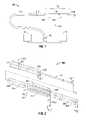
- FIG. 1is a schematic diagram of an ablation system according to an embodiment of the present disclosure
- FIG. 2is a perspective view with parts disassembled of a portion of an energy applicator according to an embodiment of the present disclosure
- FIG. 3is a perspective assembled view of the portion of the energy applicator shown in FIG. 2 according to an embodiment of the present disclosure
- FIG. 4is a perspective, partly separated view of the portion of the energy applicator of FIG. 3 provided with an elongated shaft having an opening therethrough and an end cap according to an embodiment of the present disclosure
- FIG. 5is an enlarged view of the indicated area of detail of FIG. 4 according to an embodiment of the present disclosure
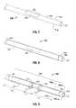
- FIG. 6is a partial, cross-sectional view of the energy applicator of FIG. 7 according to an embodiment of the present disclosure
- FIG. 7is a perspective, assembled view of the portion of the energy applicator of FIG. 4 according to an embodiment of the present disclosure
- FIG. 8is a partial, perspective view of the energy applicator of FIG. 7 shown with a dielectric sleeve member surrounding a portion of the elongated shaft including the opening in the elongated shaft, according to an embodiment of the present disclosure
- FIG. 9is a partial, perspective view of the energy applicator of FIG. 8 shown with portions of the dielectric sleeve member and the opening in the elongated shaft (in phantom lines) surrounded by axially aligned proximal and distal electrically-conductive sleeve members having a gap therebetween according to an embodiment of the present disclosure;
- FIG. 10Ais a cross-sectional view of a distal portion of the energy applicator of FIG. 9 according to an embodiment of the present disclosure
- FIG. 10Bis a cross-sectional view of another distal portion of the energy applicator of FIG. 9 according to an embodiment of the present disclosure
- FIG. 11is a partial, perspective view of the energy applicator of FIG. 9 shown with a tapered portion extending distally of the distal electrically-conductive sleeve member according to an embodiment of the present disclosure
- FIG. 12is a partial, perspective view of the energy applicator of FIG. 11 shown with a layer disposed along the length of the elongated shaft and overlying the proximal and distal electrically-conductive sleeve members and bridging the gap therebetween according to an embodiment of the present disclosure;
- FIG. 13is a diagrammatic representation of a radiation pattern of electromagnetic energy delivered into tissue by an energy applicator, such as the energy applicator of FIG. 12 , according to an embodiment of the present disclosure
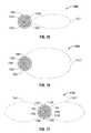
- FIG. 14is a cross-sectional view of an energy applicator shown with a diagrammatic representation of an emitted radiation pattern according to an embodiment of the present disclosure
- FIG. 15is a cross-sectional view of another embodiment of an energy applicator shown with a diagrammatic representation of an emitted radiation pattern according to the present disclosure
- FIG. 16is a cross-sectional view of yet another embodiment of an energy applicator shown with a diagrammatic representation of an emitted radiation pattern according to the present disclosure
- FIG. 17is a cross-sectional view of still another embodiment of an energy applicator shown with a diagrammatic representation of an emitted radiation pattern according to the present disclosure.
- FIG. 18is a flowchart illustrating a method of manufacturing an electrosurgical device according to an embodiment of the present disclosure
- proximalrefers to that portion of the apparatus that is closer to the user and the term “distal” refers to that portion of the apparatus that is further from the user.
- Electromagnetic energyis generally classified by increasing energy or decreasing wavelength into radio waves, microwaves, infrared, visible light, ultraviolet, X-rays and gamma-rays.
- microwavegenerally refers to electromagnetic waves in the frequency range of 300 megahertz (MHz) (3 ⁇ 10 8 cycles/second) to 300 gigahertz (GHz) (3 ⁇ 10 11 cycles/second).
- ablation proceduregenerally refers to any ablation procedure, such as microwave ablation, radio frequency (RF) ablation or microwave ablation assisted resection.
- transmission linegenerally refers to any transmission medium that can be used for the propagation of signals from one point to another.
- Various embodiments of the present disclosureprovide electrosurgical devices for treating tissue and methods of directing electromagnetic radiation to a target volume of tissue.
- Embodimentsmay be implemented using electromagnetic radiation at microwave frequencies or at other frequencies.
- An electrosurgical system including an energy applicator, according to various embodiments,is designed and configured to operate between about 500 MHz and about 10 GHz with a directional radiation pattern.
- Various embodiments of the presently disclosed electrosurgical device with a directional radiation patternare suitable for microwave ablation and for use to pre-coagulate tissue for microwave ablation assisted surgical resection.
- various methods described hereinbeloware targeted toward microwave ablation and the complete destruction of target tissue, it is to be understood that methods for directing electromagnetic radiation may be used with other therapies in which the target tissue is partially destroyed or damaged, such as, for example, to prevent the conduction of electrical impulses within heart tissue.
- the teachings of the present disclosuremay also apply to a monopole, helical, or other suitable type of microwave antenna.
- FIG. 1shows an electrosurgical system 10 , according to an embodiment of the present disclosure, which includes an energy applicator or probe 100 .
- Probe 100generally includes an antenna assembly 12 having a radiating portion connected by a feedline 110 (or shaft) via a transmission line 15 to a connector 16 , which may further operably connect the probe 100 to a power generating source 28 , e.g., a microwave or RF electrosurgical generator.
- a power generating source 28e.g., a microwave or RF electrosurgical generator.
- Feedline 110may electrically connect the antenna assembly 12 via the transmission line 15 to the generator 28 and may include a coaxial cable, which may be semi-rigid or flexible. Feedline 110 may have a variable length from a proximal end of the antenna assembly 12 to a distal end of transmission line 15 ranging from a length of about one inch to about ten inches. Feedline 110 may be constructed of a variety of electrically conductive materials, e.g., copper, gold, or other conductive metals with similar conductivity values. Feedline 110 may be made of stainless steel, which generally offers the strength required to puncture tissue and/or skin.
- Conductive materials used to form the feedline 110may be plated with other materials, e.g., other conductive materials, to improve their properties, e.g., to improve conductivity or decrease energy loss, etc.
- the feedline 110includes stainless steel, and to improve its conductivity, the stainless steel may be coated with a layer of a conductive material such as copper or gold.
- Feedline 110may include an inner conductor, a dielectric material coaxially surrounding the inner conductor, and an outer conductor coaxially surrounding the dielectric material.
- Antenna assembly 12may be formed from a portion of the inner conductor that extends distal of the feedline 110 into the antenna assembly 12 .
- Feedline 110may be cooled by fluid e.g., saline or water, to improve power handling, and may include a stainless steel catheter.
- the power generating source 28is configured to provide microwave energy at an operational frequency from about 500 MHz to about 2500 MHz. In other embodiments, the power generating source 28 is configured to provide microwave energy at an operational frequency from about 500 MHz to about 10 GHz. Power generating source 28 may be configured to provide various frequencies of electromagnetic energy. Transmission line 15 may additionally, or alternatively, provide a conduit (not shown) configured to provide coolant from a coolant source 18 to the probe 100 .
- an end cap or tapered portion 120Located at the distal end of the antenna assembly 12 is an end cap or tapered portion 120 , which may terminate in a sharp tip 123 to allow for insertion into tissue with minimal resistance.
- a straight probe with a sharp tipthat may be suitable for use as the energy applicator 100 is commercially available under the trademark EVIDENTTM offered by Covidien.
- the end cap or tapered portion 120may include other shapes, such as, for example, a tip 123 that is rounded, flat, square, hexagonal, or cylindroconical.
- the antenna assembly 12includes a distal radiating portion 105 and a proximal radiating portion 140 .
- a junction 130couples the proximal radiating portion 140 and the distal radiating portion 105 .
- the distal and proximal radiating portions 105 , 140align at the junction 130 , which is generally made of a dielectric material, e.g., adhesives, and are also supported by the inner conductor that extends at least partially through the distal radiating portion 105 .
- Junction 130or portions thereof, may be disposed between the proximal and distal radiating portions, 140 and 105 .
- Junction 130may be formed from any suitable elastomeric or ceramic dielectric material by any suitable process.
- the junction 130is formed by overmolding and includes a thermoplastic elastomer, such as, for example, polyether block amide (e.g., PEBAX®, manufactured by The Arkema Group of Colombes, France), polyetherimide (e.g., ULTEM® and/or EXTEM®, manufactured by SABIC Innovative Plastics of Saudi Arabia) and/or polyimide-based polymer (e.g., VESPEL®, manufactured by E. I. du Pont de Nemours and Company of Wilmington, Del., United States).
- Junction 130may be formed using any suitable overmolding compound by any suitable process, and may include use of a ceramic substrate.
- the antenna assembly 12may be provided with a coolant chamber (not shown). Additionally, the junction 130 may include coolant inflow and outflow ports (not shown) to facilitate the flow of coolant into, and out of, the coolant chamber. Examples of coolant chamber and coolant inflow and outflow port embodiments are disclosed in commonly assigned U.S. patent application Ser. No. 12/401,268 filed on Mar. 10, 2009, entitled “COOLED DIELECTRICALLY BUFFERED MICROWAVE DIPOLE ANTENNA”, and U.S. Pat. No. 7,311,703 entitled “DEVICES AND METHODS FOR COOLING MICROWAVE ANTENNAS”.
- the antenna assembly 12may be provided with an outer jacket (not shown) disposed about the distal radiating portion 105 , the junction 130 and/or the proximal radiating portion 140 .
- the outer jacketmay be formed of any suitable material, such as, for example, polymeric or ceramic materials.
- the outer jacketmay be applied by any suitable method, such as, for example, heat shrinking, overmolding, coating, spraying dipping, powder coating, baking and/or film deposition.
- the outer jacketmay be a water cooled catheter formed of a material having low electrical conductivity.
- the probe 100is inserted into or placed adjacent to tissue and microwave energy is supplied thereto.
- Ultrasound or computed tomography (CT) guidancemay be used to accurately guide the probe 100 into the area of tissue to be treated.
- Probe 100may be placed percutaneously or atop tissue, e.g., using conventional surgical techniques by surgical staff.
- a clinicianmay pre-determine the length of time that microwave energy is to be applied.
- Application durationmay depend on many factors such as tumor size and location and whether the tumor was a secondary or primary cancer.
- the duration of microwave energy application using the probe 100may depend on the progress of the heat distribution within the tissue area that is to be destroyed and/or the surrounding tissue.
- Single or multiple probes 100may provide ablations in short procedure times, e.g., a few minutes, to destroy cancerous cells in the target tissue region.
- a plurality of probes 100may be placed in variously arranged configurations to substantially simultaneously ablate a target tissue region, making faster procedures possible. Multiple probes 100 can be used to synergistically create a large ablation or to ablate separate sites simultaneously. Tissue ablation size and geometry is influenced by a variety of factors, such as the energy applicator design, number of energy applicators used simultaneously, time and wattage.
- microwave energy having a wavelength, lamda ( ⁇ )is transmitted through the antenna assembly 12 , e.g., along the proximal and distal radiating portions 140 , 105 , and radiated into the surrounding medium, e.g., tissue.
- the length of the antenna for efficient radiationmay be dependent on the effective wavelength, ⁇ eff , which is dependent upon the dielectric properties of the medium being radiated into.
- Antenna assembly 12 through which microwave energy is transmitted at a wavelength, ⁇may have differing effective wavelengths, ⁇ eff , depending upon the surrounding medium, e.g., liver tissue, as opposed to, e.g., breast tissue.
- FIGS. 2 through 12show a sequentially-illustrated, assembly of components forming an energy applicator or probe having a dielectric loaded coaxial aperture (e.g., “W” shown in FIG. 12 ) with distally positioned resonant structure (e.g., 909 shown in FIG. 9 ), in accordance with the present disclosure.
- a dielectric loaded coaxial aperturee.g., “W” shown in FIG. 12
- distally positioned resonant structuree.g., 909 shown in FIG. 9
- an energy applicator or probe(shown generally as 200 in FIGS. 2 and 3 ) is provided with a coaxial feedline 226 having an inner conductor 220 that extends along the longitudinal axis “A” of the energy applicator 200 , an outer conductor 224 coaxially disposed about the inner conductor 220 , and a dielectric material 222 disposed therebetween.
- the inner conductor 220has a diameter “D 1 ” and the dielectric material 222 has an outer diameter “D 2 ”.
- a portion of the dielectric material 222may extend beyond the outer conductor 224 . Additionally, or alternatively, a portion of the inner conductor 220 (e.g., 22 shown in FIG. 2 ) may extend beyond the dielectric material 222 and the outer conductor 224 .
- the antenna assembly 12may be coupled to the inner conductor portion 22 .
- the antenna assembly 12may be coupled to an elongated conductor (e.g., similar to the inner conductor portion 22 ), wherein the elongated conductor is electrically coupled to the inner conductor 220 of the feedline 226 .
- a proximal cylindrical dielectric sleeve 244may be coupled to the inner conductor 220 at a distal end of the coaxial feedline 226 . Additionally, or alternatively, a first dielectric segment 284 and a second dielectric segment 274 may be coupled to the inner conductor 220 . Additionally, or alternatively, a distal cylindrical dielectric sleeve 264 may be coupled to the inner conductor 220 .
- Proximal cylindrical dielectric sleeve 244 , first dielectric segment 284 and a second dielectric segment 274may be formed from dielectric materials that provide an impedance match from the coaxial feedline 226 .
- First dielectric segment 284may be formed from a material with a dielectric constant that is higher than the dielectric constant of the second dielectric segment 274 , e.g., to maximize energy radiated into the surrounding medium, e.g., tissue.
- a proximal cylindrical dielectric sleeve 244having a diameter “D 2 ”, is coupled to the inner conductor 220 .
- Proximal cylindrical dielectric sleeve 244may be configured with a central channel 245 extending longitudinally therethrough to accommodate the inner conductor 220 .
- Proximal cylindrical dielectric sleeve 244may be formed from any suitable dielectric material.
- the proximal cylindrical dielectric sleeve 244is formed from a material with a dielectric constant in the range of about 2 to about 10.
- a distal cylindrical dielectric sleeve 264having a diameter “D 2 ”, is coupled to the inner conductor 220 .
- Distal cylindrical dielectric sleeve 264may be formed from any suitable dielectric material.
- Distal cylindrical dielectric sleeve 264may be disposed distally of the proximal cylindrical dielectric sleeve 244 and may be configured with a central channel 265 extending longitudinally therethrough to accommodate the inner conductor 220 .
- the distal cylindrical dielectric sleeve 264is formed from a material with a dielectric constant different than the dielectric constant of the proximal cylindrical dielectric sleeve 244 .
- Distal cylindrical dielectric sleeve 264may be a high dielectric material, e.g., a material with a dielectric constant in the range of about 3 to about 50, to shorten the effective wavelength, ⁇ eff , of energy.
- the length of the distal cylindrical dielectric sleeve 264may be varied, depending on the dielectric constant of the material selected, to allow positioning of a radiating aperture (e.g., “W” shown in FIGS. 12 and 13 ) at a quarter wavelength (or half wavelength, etc.) from a distal short (e.g., “P” shown in FIGS. 4 and 6 ).
- a radiating aperturee.g., “W” shown in FIGS. 12 and 13
- a quarter wavelengthor half wavelength, etc.
- Pshown in FIGS. 4 and 6
- the physical length of the distal cylindrical dielectric sleeve 264 for a selected dielectric constant to allow positioning of an aperture at a selected wavelength from a distal shortmay be calculated using Equation 1.
- ⁇c f ⁇ ⁇ r , ( 1 )
- cthe speed of light
- fthe frequency
- ⁇ rthe dielectric constant
- first dielectric segment 284 and a second dielectric segment 274are coupled to the inner conductor 220 .
- the first and second dielectric segments 284 , 274may be disposed between the proximal cylindrical dielectric sleeve 244 and the distal cylindrical dielectric sleeve 264 .
- First and second dielectric segments 284 , 274generally include one or more flat planar surfaces and a partial cylindrical surface. The shape and size of the first and second dielectric segments 284 , 274 may be varied from the configuration depicted in FIGS. 2 through 4 (see, e.g., 1564 , 1562 and 1664 , 1662 shown in FIGS. 15 and 16 , respectively).
- the first dielectric segment 284is formed from a material with a dielectric constant in the range of about 2 to about 30.
- the second dielectric segment 274is formed from a material with a dielectric constant in the range of about 2 to about 30.
- the first dielectric segment 284has a substantially half-cylindrical shape, having a diameter “D 3 ”, and includes a flat planar surface configured with a recess in the form of a groove 287 extending longitudinally across the flat planar surface.
- the second dielectric segment 274has a substantially half-cylindrical shape, having a diameter “D 2 ”, and includes a flat planar surface configured with a recess in the form of a groove 277 extending longitudinally across the flat planar surface. Grooves 287 and 277 may be configured to accommodate a portion of the inner conductor 220 .
- first and second dielectric segments 284 , 274when the first and second dielectric segments 284 , 274 are coupled to the inner conductor 220 , the respective flat planar surfaces of the first and second dielectric segments 284 , 274 contact one another.
- the shape and size of the grooves 287 and 277may be varied from the configuration depicted in FIG. 2 .
- FIGS. 4 through 7show an energy applicator 300 , according to an embodiment of the present disclosure, which is similar to the energy applicator 200 of FIG. 3 , except for an elongated shaft 480 (outlined in bold lines in FIG. 4 ) having an opening 440 therethrough, and an end cap “P” disposed distally to the distal end of the elongated shaft 480 .
- the elongated shaft 480has an inner diameter “D 2 ” and an outer diameter “D 3 ”.
- the end cap “P”may have a disc-or plate-like shape. End cap “P” may be formed of any suitable electrically-conductive material, e.g., metal such as stainless steel, titanium, etc. As shown in FIG.
- the proximal surface “S” of the end cap “P”makes contact with both the distal end of the inner conductor 220 and the distal end of the elongated shaft 480 , thereby forming a distal short.
- the shape and size of the end cap “P”may be varied from the configuration depicted in FIGS. 4 and 6 .
- the opening 440 in the elongated shaft 480may be aligned with the first dielectric segment 284 .
- the first dielectric segment 284 and the elongated shaft 480may be substantially concentric to a longitudinal axis (e.g., “A” shown in FIG. 2 ) of the energy applicator.
- Elongated shaft 480may be electrically coupled to the outer conductor 224 of the coaxial feedline 226 .
- Opening 440is made by removing a radial portion the elongated shaft 480 an optimized length back from the distal short.
- the opening 440is positioned to maximize directivity and coupling of microwave energy into tissue, e.g., opening 440 may be placed at the voltage maximum of the standing wave created by the shorted coaxial distal end.
- Opening 440may be of any length and radial angle to achieve the desired amount of coax to free space coupling and radiation directivity.
- the dielectric constant of dielectric materials on either side of the opening 440 , proximal or distal,may vary with distance from the opening 440 to achieve impedance match and optimal energy delivery and directivity to tissue.
- the dielectric materials filling the coaxial structure at the site of the opening 440may vary in dielectric constant with shells or more complex dielectric layering to achieve the optimum antenna directivity and energy to tissue delivery.
- the first dielectric segment 284has a diameter “D 2 ” and the elongated shaft 480 has an outer diameter “D 3 ”, where “D 3 ” is larger than “D 2 ”.
- the opening 440may be filled with a nonconductive radio frequency transparent material, e.g., a glass fiber epoxy composite or polyimide. This may be accomplished in an over molding process. The window may also be created by placing a heat shrink or rigid composite sleeve along the entire antenna assembly.
- FIG. 8shows an energy applicator 400 , according to an embodiment of the present disclosure, which is similar to the energy applicator 300 of FIG. 7 , except for a dielectric sleeve member 740 (also referred to herein as a balun insulator) disposed coaxially about a portion of the elongated shaft 480 .
- Balun insulator 740may be formed of any non-conductive insulator, e.g., a Teflon® sleeve.
- Balun insulator 740may extend fully or partially over the opening 440 in the elongated shaft. In some embodiments, the balun insulator 740 extends fully over the opening 440 and the half-cylindrical dielectric member 284 disposed therein.
- balun insulator 740may be varied from the configuration depicted in FIG. 8 .
- Balun insulator 740may extend beyond the open ends of one or more electrically-conductive sleeve members (e.g., 871 , 872 shown in FIG. 9 ) of a balun structure (e.g., 909 shown in FIG. 9 ) to enhance effectiveness of the balun.
- FIG. 9shows an energy applicator 500 , according to an embodiment of the present disclosure, which is similar to the energy applicator 400 of FIG. 7 , except for a first electrically-conductive sleeve member 871 and a second electrically-conductive sleeve member 872 (also referred to herein as balun outer conductors) axially aligned with a gap 940 therebetween.
- a proximal end portion of the first electrically-conductive sleeve member 871may be coupled to a proximal portion of the elongated shaft 480 .
- a distal end portion of the second electrically-conductive sleeve member 872may be coupled to a distal portion of the elongated shaft 480 , e.g., as shown in FIG. 10A .
- First and second electrically-conductive sleeve members 871 , 872may be formed of any suitable electrically-conductive material, e.g., metal such as stainless steel, aluminum, titanium, copper, etc.
- First and second electrically-conductive sleeve members 871 , 872may overlap portions of the window 440 in the elongated shaft 480 . As shown in FIG. 9 , the first electrically-conductive sleeve member 871 may overlap a proximal portion 401 , having a length “L 1 ”, of the window 440 , and the second electrically-conductive sleeve member 872 may overlap a distal portion 402 , having a length “L 2 ”, of the window 440 , whereby a gap 940 , having a length “L 3 ”, is formed therebetween.
- the first electrically-conductive sleeve member 871has a length “L 4 ”, wherein “L 4 ” may be a quarter wavelength or a half wavelength.
- the second electrically-conductive sleeve member 872has a length “L 5 ”, wherein “L 5 ” may be a quarter wavelength or a half wavelength.
- First and second electrically-conductive sleeve members 871 , 872may have any suitable length.
- FIG. 11shows an energy applicator 600 , according to an embodiment of the present disclosure, which is similar to the energy applicator 500 of FIG. 9 , except for a tapered portion 920 extending distally from the distal end cap “P”.
- Tapered portion 920may terminate in a sharp tip 923 to allow for insertion into tissue with minimal resistance. In those cases where the energy applicator 600 is inserted into a pre-existing opening, the tip 923 may be rounded or flat.
- the shape and size of the tapered portion 920may be varied from the configuration depicted in FIG. 11 .
- FIG. 12shows an energy applicator 700 , according to an embodiment of the present disclosure.
- an outer jacket 1020may be provided to the energy applicator 600 of FIG. 11 .
- the outer jacket 1020is made of an insulating material, such as, for example, a polyimide or similar dielectric material.
- Outer jacket 1020may be a water-cooled catheter formed of a material having low electrical conductivity.
- the outer surface of the outer jacket 1020may be coated with a suitable lubricious substance, such as TEFLON®, to aid in the movement of the outer jacket 1020 in or through tissue as well as to aid in preventing tissue from sticking thereto.
- FIG. 13shows an embodiment of an energy applicator (e.g., 700 shown in FIG. 12 ) coupled to a transmission line 15 according to the present disclosure.
- Transmission line 15may connect the energy applicator 700 to a power generating source, e.g., a microwave or RF electrosurgical generator.
- a power generating sourcee.g., a microwave or RF electrosurgical generator.
- the energy applicator 700is inserted into or placed adjacent to tissue “T” and energy is supplied thereto.
- Energy applicator 700may be placed percutaneously or atop tissue.
- Ultrasound or computed tomography (CT) guidancemay be used to accurately guide the energy applicator 700 into the area of tissue “T” to be treated.
- CTcomputed tomography
- Energy applicator 700may be rotatable about a longitudinal axis “A-A” (shown in FIG. 2 ) such that the directional radiation pattern “R” rotates therewith.
- Examples of antenna assemblies rotatable about axis “A-A” such that any elongated radiation lobes rotates therewithare disclosed in commonly assigned U.S. patent application Ser. No. 12/197,405 filed on Aug. 25, 2008, entitled “MICROWAVE ANTENNA ASSEMBLY HAVING A DIELECTRIC BODY PORTION WITH RADIAL PARTITIONS OF DIELECTRIC MATERIAL”.
- Energy applicator 700may include an indicia alignment mark (not shown) such as a colored strip or the like (e.g., to provide a visual cue to the surgeon to allow orientation of the direction of flow of the energy to coincide with the indicia alignment mark) and/or indicia graduation marks (not shown) for insertion depth reference (e.g., to indicate the position of the opening “W” relative to the surface of the tissue “T”).
- indicia alignment mark and the indicia graduation mark embodimentsare disclosed in commonly assigned U.S. patent application Ser. No. 12/476,960 filed on Jun. 2, 2009, entitled “ELECTROSURGICAL DEVICES WITH DIRECTIONAL RADIATION PATTERN”.
- FIGS. 14 through 17show various configurations of dielectric material at the site of a window (e.g., “W” shown in FIG. 13 ) of an energy applicator (e.g., 700 shown in FIG. 13 ) and examples of emitted radiation patterns, according to embodiments of the present disclosure.
- a windowe.g., “W” shown in FIG. 13
- an energy applicatore.g., 700 shown in FIG. 13
- FIG. 14shows a cross-sectional view of an energy applicator 1400 and an emitted radiation pattern “R1” of microwave energy radiated therefrom.
- the windowis approximately 1 ⁇ 2 the circumference of the elongated shaft 1493 thereof.
- a first dielectric member 1464 and a second dielectric member 1462are coupled to an inner conductor 1420 at the site of the window.
- Inner conductor 1420may be similar to the inner conductor 220 shown in FIG. 2 .
- First and second dielectric members 1464 , 1462may have substantially the same diameter.
- Second dielectric member 1462may be similar to the second dielectric segment 274 shown in FIG. 2 . In the embodiment depicted in FIG.
- the elongated shaft 1493extends over the second dielectric member 1462 .
- the window in the elongated shaftis filled with a radio frequency (RF) transparent material 1485 , e.g., a glass fiber epoxy composite or polyimide.
- RFradio frequency
- FIG. 15shows a cross-sectional view of an energy applicator 1500 and an emitted radiation pattern “R2” of microwave energy radiated therefrom.
- the windowis approximately 1 ⁇ 4 the circumference of the elongated shaft 1593 thereof.
- a first dielectric member 1564 and a second dielectric member 1562are coupled to the inner conductor 1420 at the site of the window.
- the elongated shaft 1593extends fully over the second dielectric member 1562 and partially over the first dielectric member 1564 .
- the window in the elongated shaft 1593 of the energy applicator 1500is filled with a RF transparent material 1585 .
- FIG. 16shows a cross-sectional view of an energy applicator 1600 and an emitted radiation pattern “R3” of microwave energy radiated therefrom.
- the windowis approximately 4 ⁇ 5 the circumference of the elongated shaft 1693 .
- a first dielectric member 1664 and a second dielectric member 1662are coupled to the inner conductor 1420 at the site of the window.
- the window and the RF transparent material 1685 disposed thereinextends fully over the first dielectric member 1664 and partially over the second dielectric member 1664 .
- FIG. 17shows a cross-sectional view of an energy applicator 1700 having two windows and two emitted radiation patterns “R4” and “R5” of microwave energy radiated therefrom.
- each of the two windowsis approximately 114 the circumference of the elongated shaft 1793 thereof.
- a RF transparent material 1785is disposed in each of the windows.
- Energy applicator 1700includes a first dielectric segment 1764 , a second dielectric segment 1762 , a third dielectric segment 1768 and a fourth dielectric segment 1766 , each coupled to the inner conductor 1420 .
- the shape and size of the first, second, third and fourth dielectric segmentsmay be varied from the configuration depicted in FIG. 17 .
- FIG. 18is a flowchart illustrating a method of manufacturing an electrosurgical device according to an embodiment of the present disclosure.
- a coaxial feedlinee.g., 226 shown in FIG. 2
- the coaxial feedlineincludes an inner conductor (e.g., 220 shown in FIG. 2 ), an outer conductor (e.g., 224 shown in FIG. 2 ), and a dielectric material (e.g., 222 shown in FIG. 2 ) disposed therebetween.
- a first dielectric member(e.g., 244 shown in FIG. 3 ) is joined to a portion of the inner conductor (e.g., 22 shown in FIG. 2 ) extending beyond the dielectric material and the outer conductor at a distal end of the coaxial feedline.
- the first dielectric membermay have a substantially cylindrical shape, and may be configured with a central channel (e.g., 245 shown in FIG. 2 ) extending longitudinally therethrough to accommodate the inner conductor.
- a second dielectric member(e.g., 284 shown in FIG. 3 ) is joined to a portion of the inner conductor extending beyond the first dielectric member at a distal end of the first dielectric member.
- the second dielectric membermay have a substantially half-cylindrical shape including a flat planar surface and a half cylindrical surface.
- the flat planar surface of the second dielectric membermay be configured with a recess in the form of a groove (e.g., 287 shown in FIG. 2 ) extending longitudinally thereacross.
- a third dielectric member shaft(e.g., 274 shown in FIG. 3 ) is joined to the portion of the inner conductor extending beyond the first dielectric member at a distal end of the first dielectric member.
- the third dielectric membermay have a substantially half-cylindrical shape including a flat planar surface and a half cylindrical surface.
- the flat planar surface of the third dielectric membermay be configured with a recess in the form of a groove defined therein (e.g., 277 shown in FIG. 2 ) extending longitudinally thereacross.
- a fourth dielectric member shaft(e.g., 264 shown in FIG. 3 ) is joined to a portion of the inner conductor extending beyond the second and third dielectric members at a distal end of the second and third dielectric members.
- the fourth dielectric membermay have a substantially cylindrical shape, and may be configured with a central channel defined therein (e.g., 265 shown in FIG. 2 ) extending longitudinally therethrough to accommodate the inner conductor.
- an elongated shaft(e.g., 480 shown in FIG. 4 ) having an opening defined therethrough is positioned overlying the first, second, third and fourth dielectric members, such that the opening (e.g., 440 shown in FIG. 4 ) is aligned with the third dielectric member.
- the third dielectric memberis configured to fill the opening in the elongated shaft (e.g., 480 ).
- the opening in the elongated shaft (e.g., 480 )is filled with a RF transparent material (e.g., 1485 , 1585 , 1685 , 1783 and 1787 shown in FIGS. 14 through 17 ).
- a balun structure(e.g., 909 shown in FIG. 9 ), which includes a first balun outer conductor (e.g., 871 shown in FIG. 9 ) and a second balun outer conductor (e.g., 872 shown in FIG. 9 ) is formed onto the elongated shaft (e.g., 480 shown in FIG. 9 ), such that the first and second balun outer conductors (e.g., 871 , 872 ) are each disposed at least partially overlying the opening in the elongated shaft (e.g., 480 ).
- Step 1870may further include the steps of forming a balun insulator (e.g., 740 shown in FIG.
- balun outer conductor 8extending over an outer surface of the elongated shaft (e.g., 480 shown in FIG. 8 ), and positioning the first and second balun outer conductors (e.g., 871 , 872 ) on the balun insulator (e.g., 740 shown in FIG. 9 ), wherein a distal end of the second balun outer conductor (e.g., 872 ) is positioned adjacent to a distal end of a balun short (e.g., “P” shown in FIG. 9 ).
- a balun shorte.g., “P” shown in FIG. 9
- the above-described electrosurgical devices for treating tissue and methods of directing electromagnetic radiation to a target volume of tissuemay be used to provide directional microwave ablation, wherein the heating zone may be focused to one side of the electrosurgical device, thereby allowing clinicians to target small and/or hard to access tumors without having to penetrate the tumor directly or kill more healthy tissue than necessary.
- the presently disclosed electrosurgical devicesmay allow clinicians to avoid ablating or unnecessarily heating tissue structures, such as large vessels, healthy organs or vital membrane barriers, by placing the electrosurgical device between the tumor and tissue structure and directing the electromagnetic radiation toward the tumor and away from the tissue structure.
Landscapes
- Health & Medical Sciences (AREA)
- Surgery (AREA)
- Life Sciences & Earth Sciences (AREA)
- Biomedical Technology (AREA)
- Medical Informatics (AREA)
- Nuclear Medicine, Radiotherapy & Molecular Imaging (AREA)
- Veterinary Medicine (AREA)
- Engineering & Computer Science (AREA)
- Public Health (AREA)
- Heart & Thoracic Surgery (AREA)
- Otolaryngology (AREA)
- Molecular Biology (AREA)
- Animal Behavior & Ethology (AREA)
- General Health & Medical Sciences (AREA)
- Physics & Mathematics (AREA)
- Electromagnetism (AREA)
- Surgical Instruments (AREA)
Abstract
Description
where c is the speed of light, f is the frequency, and ∈ris the dielectric constant. For example, in a case where an aperture is to be positioned at a quarter wavelength, given a dielectric sleeve having a dielectric constant ∈r, using Equation 1, the length l of the dielectric sleeve is calculated as:
Claims (15)
Priority Applications (8)
| Application Number | Priority Date | Filing Date | Title |
|---|---|---|---|
| US12/535,851US8328799B2 (en) | 2009-08-05 | 2009-08-05 | Electrosurgical devices having dielectric loaded coaxial aperture with distally positioned resonant structure |
| EP15175824.0AEP2962655B1 (en) | 2009-08-05 | 2010-08-04 | Antenna assembly and electrosurgical device |
| CA2712140ACA2712140C (en) | 2009-08-05 | 2010-08-04 | Electrosurgical devices having dielectric loaded coaxial aperture with distally positioned resonant structure and method of manufacturing same |
| EP10008139.7AEP2281522B1 (en) | 2009-08-05 | 2010-08-04 | Electrosurgical devices having dielectric loaded coaxial aperture with distally positioned resonant structure and method of manufacturing the same |
| AU2010206116AAU2010206116B2 (en) | 2009-08-05 | 2010-08-04 | Electrosurgical devices having dielectric loaded coaxial aperture with distally positioned resonant structure and method of manufacturing same |
| JP2010175112AJP5651402B2 (en) | 2009-08-05 | 2010-08-04 | Electrosurgical device having a dielectric loaded coaxial opening with a distally located resonant structure and method of manufacturing the same |
| US13/711,086US8968300B2 (en) | 2009-08-05 | 2012-12-11 | Electrosurgical devices having dielectric loaded coaxial aperture with distally positioned resonant structure |
| US14/604,261US10213255B2 (en) | 2009-08-05 | 2015-01-23 | Electrosurgical devices having dielectric loaded coaxial aperture with distally positioned resonant structure and method of manufacturing same |
Applications Claiming Priority (1)
| Application Number | Priority Date | Filing Date | Title |
|---|---|---|---|
| US12/535,851US8328799B2 (en) | 2009-08-05 | 2009-08-05 | Electrosurgical devices having dielectric loaded coaxial aperture with distally positioned resonant structure |
Related Child Applications (1)
| Application Number | Title | Priority Date | Filing Date |
|---|---|---|---|
| US13/711,086ContinuationUS8968300B2 (en) | 2009-08-05 | 2012-12-11 | Electrosurgical devices having dielectric loaded coaxial aperture with distally positioned resonant structure |
Publications (2)
| Publication Number | Publication Date |
|---|---|
| US20110034917A1 US20110034917A1 (en) | 2011-02-10 |
| US8328799B2true US8328799B2 (en) | 2012-12-11 |
Family
ID=43066726
Family Applications (3)
| Application Number | Title | Priority Date | Filing Date |
|---|---|---|---|
| US12/535,851Expired - Fee RelatedUS8328799B2 (en) | 2009-08-05 | 2009-08-05 | Electrosurgical devices having dielectric loaded coaxial aperture with distally positioned resonant structure |
| US13/711,086Active2030-04-13US8968300B2 (en) | 2009-08-05 | 2012-12-11 | Electrosurgical devices having dielectric loaded coaxial aperture with distally positioned resonant structure |
| US14/604,261Active2032-02-02US10213255B2 (en) | 2009-08-05 | 2015-01-23 | Electrosurgical devices having dielectric loaded coaxial aperture with distally positioned resonant structure and method of manufacturing same |
Family Applications After (2)
| Application Number | Title | Priority Date | Filing Date |
|---|---|---|---|
| US13/711,086Active2030-04-13US8968300B2 (en) | 2009-08-05 | 2012-12-11 | Electrosurgical devices having dielectric loaded coaxial aperture with distally positioned resonant structure |
| US14/604,261Active2032-02-02US10213255B2 (en) | 2009-08-05 | 2015-01-23 | Electrosurgical devices having dielectric loaded coaxial aperture with distally positioned resonant structure and method of manufacturing same |
Country Status (4)
| Country | Link |
|---|---|
| US (3) | US8328799B2 (en) |
| EP (2) | EP2962655B1 (en) |
| JP (1) | JP5651402B2 (en) |
| CA (1) | CA2712140C (en) |
Cited By (28)
| Publication number | Priority date | Publication date | Assignee | Title |
|---|---|---|---|---|
| US20110060326A1 (en)* | 2009-09-09 | 2011-03-10 | Vivant Medical, Inc. | System and Method for Performing an Ablation Procedure |
| US8652127B2 (en) | 2010-05-26 | 2014-02-18 | Covidien Lp | System and method for chemically cooling an ablation antenna |
| US9028476B2 (en) | 2011-02-03 | 2015-05-12 | Covidien Lp | Dual antenna microwave resection and ablation device, system and method of use |
| US9192437B2 (en) | 2009-05-27 | 2015-11-24 | Covidien Lp | Narrow gauge high strength choked wet tip microwave ablation antenna |
| US9192440B2 (en) | 2010-02-05 | 2015-11-24 | Covidien Lp | Electrosurgical devices with choke shorted to biological tissue |
| US20160005589A1 (en)* | 2013-03-15 | 2016-01-07 | Consiglio Nazionale Delle Ricerche | Extended microwave powered lamp |
| US9241762B2 (en) | 2010-06-03 | 2016-01-26 | Covidien Lp | Specific absorption rate measurement and energy-delivery device characterization using image analysis |
| US9271788B2 (en) | 2010-03-26 | 2016-03-01 | Cividien LP | Ablation devices with adjustable radiating section lengths, electrosurgical systems including same, and methods of adjusting ablation fields using same |
| US9375278B2 (en) | 2009-09-18 | 2016-06-28 | Covidien Lp | Tissue ablation system with energy distribution |
| US9480527B2 (en) | 2010-03-08 | 2016-11-01 | Covidien Lp | Microwave antenna probe having a deployable ground plane |
| US9610122B2 (en) | 2013-03-29 | 2017-04-04 | Covidien Lp | Step-down coaxial microwave ablation applicators and methods for manufacturing same |
| USRE46362E1 (en) | 2009-11-16 | 2017-04-11 | Covidien Lp | Twin sealing chamber hub |
| US10028787B2 (en) | 2010-02-26 | 2018-07-24 | Covidien Lp | Tunable microwave ablation probe |
| US10213256B2 (en) | 2009-10-28 | 2019-02-26 | Covidien Lp | System and method for monitoring ablation size |
| US10213255B2 (en) | 2009-08-05 | 2019-02-26 | Covidien Lp | Electrosurgical devices having dielectric loaded coaxial aperture with distally positioned resonant structure and method of manufacturing same |
| US10251701B2 (en) | 2010-05-25 | 2019-04-09 | Covidien Lp | Flow rate verification monitor for fluid-cooled microwave ablation probe |
| US10327845B2 (en) | 2010-01-25 | 2019-06-25 | Covidien Lp | System and method for monitoring ablation size |
| US10376309B2 (en) | 2016-08-02 | 2019-08-13 | Covidien Lp | Ablation cable assemblies and a method of manufacturing the same |
| US10390882B2 (en) | 2009-09-29 | 2019-08-27 | Covidien Lp | Flow rate monitor for fluid cooled microwave ablation probe |
| US10588684B2 (en) | 2010-07-19 | 2020-03-17 | Covidien Lp | Hydraulic conductivity monitoring to initiate tissue division |
| US10624697B2 (en) | 2014-08-26 | 2020-04-21 | Covidien Lp | Microwave ablation system |
| US10675089B2 (en) | 2009-09-29 | 2020-06-09 | Covidien Lp | Management of voltage standing wave ratio at skin surface during microwave ablation |
| US10813691B2 (en) | 2014-10-01 | 2020-10-27 | Covidien Lp | Miniaturized microwave ablation assembly |
| US10856940B2 (en) | 2016-03-02 | 2020-12-08 | Covidien Lp | Ablation antenna including customizable reflectors |
| US10987152B2 (en) | 2010-02-19 | 2021-04-27 | Covidien Lp | Ablation devices with dual operating frequencies, systems including same, and methods of adjusting ablation volume using same |
| US11065053B2 (en) | 2016-08-02 | 2021-07-20 | Covidien Lp | Ablation cable assemblies and a method of manufacturing the same |
| US11197715B2 (en) | 2016-08-02 | 2021-12-14 | Covidien Lp | Ablation cable assemblies and a method of manufacturing the same |
| US11678934B2 (en) | 2012-08-07 | 2023-06-20 | Covidien Lp | Microwave ablation system |
Families Citing this family (32)
| Publication number | Priority date | Publication date | Assignee | Title |
|---|---|---|---|---|
| US7553309B2 (en) | 2004-10-08 | 2009-06-30 | Covidien Ag | Electrosurgical system employing multiple electrodes and method thereof |
| US8552915B2 (en) | 2009-06-19 | 2013-10-08 | Covidien Lp | Microwave ablation antenna radiation detector |
| US8323275B2 (en) | 2009-06-19 | 2012-12-04 | Vivant Medical, Inc. | Laparoscopic port with microwave rectifier |
| US8328800B2 (en)* | 2009-08-05 | 2012-12-11 | Vivant Medical, Inc. | Directive window ablation antenna with dielectric loading |
| US8328801B2 (en)* | 2009-08-17 | 2012-12-11 | Vivant Medical, Inc. | Surface ablation antenna with dielectric loading |
| US8069553B2 (en) | 2009-09-09 | 2011-12-06 | Vivant Medical, Inc. | Method for constructing a dipole antenna |
| US8568401B2 (en) | 2009-10-27 | 2013-10-29 | Covidien Lp | System for monitoring ablation size |
| US8382750B2 (en)* | 2009-10-28 | 2013-02-26 | Vivant Medical, Inc. | System and method for monitoring ablation size |
| US8394092B2 (en)* | 2009-11-17 | 2013-03-12 | Vivant Medical, Inc. | Electromagnetic energy delivery devices including an energy applicator array and electrosurgical systems including same |
| US10039601B2 (en) | 2010-03-26 | 2018-08-07 | Covidien Lp | Ablation devices with adjustable radiating section lengths, electrosurgical systems including same, and methods of adjusting ablation fields using same |
| US8672933B2 (en) | 2010-06-30 | 2014-03-18 | Covidien Lp | Microwave antenna having a reactively-loaded loop configuration |
| JP5763263B2 (en) | 2011-04-08 | 2015-08-12 | コビディエン エルピー | Flexible microwave catheter for natural or artificial lumens |
| US8992413B2 (en) | 2011-05-31 | 2015-03-31 | Covidien Lp | Modified wet tip antenna design |
| US9113930B2 (en) | 2012-01-05 | 2015-08-25 | Covidien Lp | Ablation systems, probes, and methods for reducing radiation from an ablation probe into the environment |
| CN104507408B (en) | 2012-06-22 | 2017-06-20 | 柯惠有限合伙公司 | For the microwave thermometric of microwave ablation system |
| US9901398B2 (en) | 2012-06-29 | 2018-02-27 | Covidien Lp | Microwave antenna probes |
| US9668802B2 (en) | 2012-10-02 | 2017-06-06 | Covidien Lp | Devices and methods for optical detection of tissue contact |
| US9993283B2 (en) | 2012-10-02 | 2018-06-12 | Covidien Lp | Selectively deformable ablation device |
| US9901399B2 (en) | 2012-12-17 | 2018-02-27 | Covidien Lp | Ablation probe with tissue sensing configuration |
| US9161814B2 (en)* | 2013-03-15 | 2015-10-20 | Covidien Lp | Microwave energy-delivery device and system |
| US10765477B2 (en)* | 2014-03-10 | 2020-09-08 | Wisconsin Alumni Research Foundation | Microwave ablation antenna system |
| GB2545465A (en) | 2015-12-17 | 2017-06-21 | Creo Medical Ltd | Electrosurgical probe for delivering microwave energy |
| US10813692B2 (en) | 2016-02-29 | 2020-10-27 | Covidien Lp | 90-degree interlocking geometry for introducer for facilitating deployment of microwave radiating catheter |
| US10290943B2 (en) | 2016-11-14 | 2019-05-14 | Amphenol Antenna Solutions, Inc. | Sleeve monopole antenna with spatially variable dielectric loading |
| US20180138597A1 (en)* | 2016-11-14 | 2018-05-17 | Amphenol Antenna Solutions, Inc. | Sleeve monopole antenna with spatially variable dielectric loading |
| GB2559595B (en)* | 2017-02-10 | 2021-09-01 | Creo Medical Ltd | Electrosurgical apparatus and electrosurgical instrument |
| US10707581B2 (en) | 2018-01-03 | 2020-07-07 | Wisconsin Alumni Research Foundation | Dipole antenna for microwave ablation |
| EP3745975B1 (en)* | 2018-02-02 | 2024-07-03 | Varian Medical Systems, Inc. | Microwave ablation antennas |
| GB2573823A (en)* | 2018-05-19 | 2019-11-20 | Creo Medical Ltd | Electrosurgical ablation instrument |
| GB2579561B (en)* | 2018-12-03 | 2022-10-19 | Creo Medical Ltd | Electrosurgical instrument |
| US10750932B1 (en)* | 2019-06-11 | 2020-08-25 | Steris Instrument Management Services, Inc. | Method of assembling endoscope optical components |
| WO2022084825A1 (en)* | 2020-10-19 | 2022-04-28 | Baylis Medical Company Inc. | Medical tubular assembly |
Citations (99)
| Publication number | Priority date | Publication date | Assignee | Title |
|---|---|---|---|---|
| SU166452A1 (en) | В. А. Костров , Л. В. Смирнов | STOMATOLOGICAL DIATHERMOKOAGULATOR | ||
| DE390937C (en) | 1922-10-13 | 1924-03-03 | Adolf Erb | Device for internal heating of furnace furnaces for hardening, tempering, annealing, quenching and melting |
| DE1099658B (en) | 1959-04-29 | 1961-02-16 | Siemens Reiniger Werke Ag | Automatic switch-on device for high-frequency surgical devices |
| FR1275415A (en) | 1960-09-26 | 1961-11-10 | Device for detecting disturbances for electrical installations, in particular electrosurgery | |
| DE1139927B (en) | 1961-01-03 | 1962-11-22 | Friedrich Laber | High-frequency surgical device |
| DE1149832B (en) | 1961-02-25 | 1963-06-06 | Siemens Reiniger Werke Ag | High frequency surgical apparatus |
| FR1347865A (en) | 1962-11-22 | 1964-01-04 | Improvements to diathermo-coagulation devices | |
| DE1439302A1 (en) | 1963-10-26 | 1969-01-23 | Siemens Ag | High-frequency surgical device |
| SU401367A1 (en) | 1971-10-05 | 1973-10-12 | Тернопольский государственный медицинский институт | BIAKTIVNYE ELECTRO SURGICAL INSTRUMENT |
| FR2235669A1 (en) | 1973-07-07 | 1975-01-31 | Lunacek Boris | Gynaecological sterilisation instrument - has hollow electrode protruding from the end of a curved ended tube |
| DE2439587A1 (en) | 1973-08-23 | 1975-02-27 | Matburn Holdings Ltd | ELECTROSURGICAL DEVICE |
| DE2455174A1 (en) | 1973-11-21 | 1975-05-22 | Termiflex Corp | INPUT / OUTPUT DEVICE FOR DATA EXCHANGE WITH DATA PROCESSING DEVICES |
| DE2407559A1 (en) | 1974-02-16 | 1975-08-28 | Dornier System Gmbh | Tissue heat treatment probe - has water cooling system which ensures heat development only in treated tissues |
| DE2415263A1 (en) | 1974-03-29 | 1975-10-02 | Aesculap Werke Ag | Surgical H.F. coagulation probe has electrode tongs - with exposed ends of insulated conductors forming tong-jaws |
| DE2429021A1 (en) | 1974-06-18 | 1976-01-08 | Erbe Elektromedizin | Remote control for HF surgical instruments - uses cable with two conductors at most |
| FR2276027A1 (en) | 1974-06-25 | 1976-01-23 | Medical Plastics Inc | Plate electrode with connector - is clamped between connector jaws held by releasable locking device |
| DE2460481A1 (en) | 1974-12-20 | 1976-06-24 | Delma Elektro Med App | Electrode grip for remote HF surgical instrument switching - has shaped insulated piece with contact ring of sterilizable (silicon) rubber |
| DE2602517A1 (en) | 1975-01-23 | 1976-07-29 | Dentsply Int Inc | ELECTROSURGICAL DEVICE |
| DE2504280A1 (en) | 1975-02-01 | 1976-08-05 | Hans Heinrich Prof Dr Meinke | DEVICE FOR ELECTRIC TISSUE CUTTING IN SURGERY |
| FR2313708A1 (en) | 1975-06-02 | 1976-12-31 | Sybron Corp | Electro surgical instrument impulse control circuit - has potentiometer between patient electrodes and threshold switch for excessive voltage |
| DE2627679A1 (en) | 1975-06-26 | 1977-01-13 | Marcel Lamidey | HEMATISTIC HIGH FREQUENCY EXTRACTOR FORCEPS |
| DE2540968A1 (en) | 1975-09-13 | 1977-03-17 | Erbe Elektromedizin | Circuit for bipolar coagulation tweezers - permits preparation of tissues prior to coagulation |
| DE2820908A1 (en) | 1977-05-16 | 1978-11-23 | Joseph Skovajsa | DEVICE FOR THE LOCAL TREATMENT OF A PATIENT IN PARTICULAR FOR ACUPUNCTURE OR AURICULAR THERAPY |
| DE2803275A1 (en) | 1978-01-26 | 1979-08-02 | Aesculap Werke Ag | HF surgical appts. with active treatment and patient electrodes - has sensor switching generator to small voltage when hand-operated switch is closed |
| DE2823291A1 (en) | 1978-05-27 | 1979-11-29 | Rainer Ing Grad Koch | Coagulation instrument automatic HF switching circuit - has first lead to potentiometer and second to transistor base |
| SU727201A2 (en) | 1977-11-02 | 1980-04-15 | Киевский Научно-Исследовательский Институт Нейрохирургии | Electric surgical apparatus |
| DE2946728A1 (en) | 1979-11-20 | 1981-05-27 | Erbe Elektromedizin GmbH & Co KG, 7400 Tübingen | HF surgical appts. for use with endoscope - provides cutting or coagulation current at preset intervals and of selected duration |
| DE3143421A1 (en) | 1980-11-04 | 1982-05-27 | The Agency of Industrial Science and Technology, Tokyo | Laser scalpel |
| DE3045996A1 (en) | 1980-12-05 | 1982-07-08 | Medic Eschmann Handelsgesellschaft für medizinische Instrumente mbH, 2000 Hamburg | Electro-surgical scalpel instrument - has power supply remotely controlled by surgeon |
| FR2502935A1 (en) | 1981-03-31 | 1982-10-08 | Dolley Roger | Diathermic knife for coagulating tissues - has monitoring current added to HF coagulating current in order to control end of operation as function or resistance of coagulating tissues |
| DE3120102A1 (en) | 1981-05-20 | 1982-12-09 | F.L. Fischer GmbH & Co, 7800 Freiburg | ARRANGEMENT FOR HIGH-FREQUENCY COAGULATION OF EGG WHITE FOR SURGICAL PURPOSES |
| FR2517953A1 (en) | 1981-12-10 | 1983-06-17 | Alvar Electronic | Diaphanometer for optical examination of breast tissue structure - measures tissue transparency using two plates and optical fibre bundle cooperating with photoelectric cells |
| FR2573301A1 (en) | 1984-11-16 | 1986-05-23 | Lamidey Gilles | Surgical forceps and its control and monitoring apparatus |
| DE3510586A1 (en) | 1985-03-23 | 1986-10-02 | Erbe Elektromedizin GmbH, 7400 Tübingen | Control device for a high-frequency surgical instrument |
| US4674481A (en) | 1983-10-31 | 1987-06-23 | Board Of Regents, The University Of Texas System | RF electromagnetic field generation apparatus for regionally-focused hyperthermia |
| DE3604823A1 (en) | 1986-02-15 | 1987-08-27 | Flachenecker Gerhard | HIGH FREQUENCY GENERATOR WITH AUTOMATIC PERFORMANCE CONTROL FOR HIGH FREQUENCY SURGERY |
| EP0246350A1 (en) | 1986-05-23 | 1987-11-25 | Erbe Elektromedizin GmbH. | Coagulation electrode |
| DE8712328U1 (en) | 1987-09-11 | 1988-02-18 | Jakoubek, Franz, 7201 Emmingen-Liptingen | Endoscopy forceps |
| DE3711511C1 (en) | 1987-04-04 | 1988-06-30 | Hartmann & Braun Ag | Method for determining gas concentrations in a gas mixture and sensor for measuring thermal conductivity |
| US4776086A (en)* | 1986-02-27 | 1988-10-11 | Kasevich Associates, Inc. | Method and apparatus for hyperthermia treatment |
| US4823812A (en)* | 1986-05-12 | 1989-04-25 | Biodan Medical Systems Ltd. | Applicator for insertion into a body opening for medical purposes |
| US4825880A (en) | 1987-06-19 | 1989-05-02 | The Regents Of The University Of California | Implantable helical coil microwave antenna |
| DE3904558A1 (en) | 1989-02-15 | 1990-08-23 | Flachenecker Gerhard | Radio-frequency generator with automatic power control for radio-frequency surgery |
| DE3942998A1 (en) | 1989-12-27 | 1991-07-04 | Delma Elektro Med App | Electro-surgical HF instrument for contact coagulation - has monitoring circuit evaluating HF voltage at electrodes and delivering switch=off signal |
| EP0481685A1 (en) | 1990-10-15 | 1992-04-22 | Cook Incorporated | Medical device for localizing a lesion |
| EP0521264A2 (en) | 1991-07-03 | 1993-01-07 | W.L. Gore & Associates GmbH | Antenna device with feed |
| JPH055106A (en) | 1990-07-31 | 1993-01-14 | Matsushita Electric Works Ltd | Production of alloy sintered body |
| JPH0540112A (en) | 1991-02-08 | 1993-02-19 | Tokico Ltd | Sample liquid component analyzer |
| DE4238263A1 (en) | 1991-11-15 | 1993-05-19 | Minnesota Mining & Mfg | Adhesive comprising hydrogel and crosslinked polyvinyl:lactam - is used in electrodes for biomedical application providing low impedance and good mechanical properties when water and/or moisture is absorbed from skin |
| EP0541930A1 (en) | 1991-10-17 | 1993-05-19 | Acufex Microsurgical Inc. | Transmission link for use in surgical instruments |
| EP0556705A1 (en) | 1992-02-20 | 1993-08-25 | DELMA ELEKTRO-UND MEDIZINISCHE APPARATEBAU GESELLSCHAFT mbH | High frequency surgery device |
| EP0558429A1 (en) | 1992-02-26 | 1993-09-01 | PECHINEY RECHERCHE (Groupement d'Intérêt Economique géré par l'ordonnance no. 67-821 du 23 Septembre 1967) | Method of simultaneous measuring of electrical resistivety and thermal conductivity |
| EP0572131A1 (en) | 1992-05-21 | 1993-12-01 | Everest Medical Corporation | Surgical scissors with bipolar coagulation feature |
| US5300068A (en) | 1992-04-21 | 1994-04-05 | St. Jude Medical, Inc. | Electrosurgical apparatus |
| DE4303882A1 (en) | 1993-02-10 | 1994-08-18 | Kernforschungsz Karlsruhe | Combined instrument for separating and coagulating in minimally invasive surgery |
| JPH06343644A (en) | 1993-05-04 | 1994-12-20 | Gyrus Medical Ltd | Surgical peritoneoscope equipment |
| DE4339049A1 (en) | 1993-11-16 | 1995-05-18 | Erbe Elektromedizin | Surgical system and instruments configuration device |
| JPH07265328A (en) | 1993-11-01 | 1995-10-17 | Gyrus Medical Ltd | Electrode assembly for electric surgery device and electric surgery device using it |
| JPH0856955A (en) | 1994-06-29 | 1996-03-05 | Gyrus Medical Ltd | Electric surgical apparatus |
| JPH08252263A (en) | 1994-12-21 | 1996-10-01 | Gyrus Medical Ltd | Electronic surgical incision instrument and electronic surgical incision device using the same |
| DE29616210U1 (en) | 1996-09-18 | 1996-11-14 | Olympus Winter & Ibe Gmbh, 22045 Hamburg | Handle for surgical instruments |
| JPH0910223A (en) | 1995-06-23 | 1997-01-14 | Gyrus Medical Ltd | Generator and system for electric operation |
| DE19608716C1 (en) | 1996-03-06 | 1997-04-17 | Aesculap Ag | Bipolar surgical holding instrument |
| EP0836868A2 (en) | 1996-10-18 | 1998-04-22 | Gebr. Berchtold GmbH & Co. | High frequency surgical apparatus and method for operating same |
| DE19751106A1 (en) | 1996-11-27 | 1998-05-28 | Eastman Kodak Co | Laser printer with array of laser diodes |
| DE19717411A1 (en) | 1997-04-25 | 1998-11-05 | Aesculap Ag & Co Kg | Monitoring of thermal loading of patient tissue in contact region of neutral electrode of HF treatment unit |
| DE19751108A1 (en) | 1997-11-18 | 1999-05-20 | Beger Frank Michael Dipl Desig | Electrosurgical operation tool, especially for diathermy |
| DE19801173C1 (en) | 1998-01-15 | 1999-07-15 | Kendall Med Erzeugnisse Gmbh | Clamp connector for film electrodes |
| JPH11244298A (en) | 1997-12-19 | 1999-09-14 | Gyrus Medical Ltd | Electric surgical instrument |
| US5957969A (en)* | 1993-05-14 | 1999-09-28 | Fidus Medical Technology Corporation | Tunable microwave ablation catheter system and method |
| US6016452A (en) | 1996-03-19 | 2000-01-18 | Kasevich; Raymond S. | Dynamic heating method and radio frequency thermal treatment |
| DE19848540A1 (en) | 1998-10-21 | 2000-05-25 | Reinhard Kalfhaus | Circuit layout and method for operating a single- or multiphase current inverter connects an AC voltage output to a primary winding and current and a working resistance to a transformer's secondary winding and current. |
| EP1034748A1 (en) | 1999-03-05 | 2000-09-13 | Gyrus Medical Limited | UHF electrosurgery system |
| WO2000053112A2 (en) | 1999-03-05 | 2000-09-14 | Gyrus Medical Limited | Dual frequency electrosurgery system |
| EP1055400A1 (en) | 1999-05-28 | 2000-11-29 | Gyrus Medical Limited | An electrosurgical instrument |
| JP2000342599A (en) | 1999-05-21 | 2000-12-12 | Gyrus Medical Ltd | Generator for electrosurgical operation, electrosurgical operation system, method for operating this system and method for performing amputation and resection of tissue by electrosurgical operation |
| JP2000350732A (en) | 1999-05-21 | 2000-12-19 | Gyrus Medical Ltd | Electrosurgical system, generator for electrosurgery, and method for cutting or excising tissue by electrosurgery |
| JP2001008944A (en) | 1999-05-28 | 2001-01-16 | Gyrus Medical Ltd | Electric surgical signal generator and electric surgical system |
| JP2001029356A (en) | 1999-06-11 | 2001-02-06 | Gyrus Medical Ltd | Electric and surgical signal generator |
| US6245062B1 (en)* | 1998-10-23 | 2001-06-12 | Afx, Inc. | Directional reflector shield assembly for a microwave ablation instrument |
| EP1159926A2 (en) | 2000-06-03 | 2001-12-05 | Aesculap Ag | Scissor- or forceps-like surgical instrument |
| US20020022836A1 (en)* | 1999-03-05 | 2002-02-21 | Gyrus Medical Limited | Electrosurgery system |
| US6398781B1 (en) | 1999-03-05 | 2002-06-04 | Gyrus Medical Limited | Electrosurgery system |
| US20030083654A1 (en)* | 2000-12-29 | 2003-05-01 | Afx, Inc. | Tissue ablation system with a sliding ablating device and method |
| WO2003039385A2 (en) | 2001-11-02 | 2003-05-15 | Vivant Medical, Inc. | High-strength microwave antenna assemblies and methods of use |
| US6582427B1 (en) | 1999-03-05 | 2003-06-24 | Gyrus Medical Limited | Electrosurgery system |
| DE10224154A1 (en) | 2002-05-27 | 2003-12-18 | Celon Ag Medical Instruments | Application device for electrosurgical device for body tissue removal via of HF current has electrode subset selected from active electrode set in dependence on measured impedance of body tissue |
| DE10328514B3 (en) | 2003-06-20 | 2005-03-03 | Aesculap Ag & Co. Kg | Endoscopic surgical scissor instrument has internal pushrod terminating at distal end in transverse cylindrical head |
| US6878147B2 (en) | 2001-11-02 | 2005-04-12 | Vivant Medical, Inc. | High-strength microwave antenna assemblies |
| FR2862813A1 (en) | 2003-11-20 | 2005-05-27 | Pellenc Sa | METHOD FOR BALANCED LOADING OF LITHIUM-ION OR POLYMER LITHIUM BATTERY |
| FR2864439A1 (en) | 2003-12-30 | 2005-07-01 | Image Guided Therapy | Tumor treating device for use by surgeon, has generator applying voltage to each of active electrodes in manner independent from other electrodes and having sinusoidal voltage generation unit adjusting amplitude and phase of voltage |
| DE102004022206A1 (en) | 2004-05-04 | 2005-12-01 | Bundesrepublik Deutschland, vertr. d. d. Bundesministerium für Wirtschaft und Arbeit, dieses vertr. d. d. Präsidenten der Physikalisch-Technischen Bundesanstalt | Sensor for measuring thermal conductivity comprises a strip composed of two parallel sections, and two outer heating strips |
| DE202005015147U1 (en) | 2005-09-26 | 2006-02-09 | Health & Life Co., Ltd., Chung-Ho | Biosensor test strip with identifying function for biological measuring instruments has functioning electrode and counter electrode, identification zones with coating of electrically conductive material and reaction zone |
| US20060155270A1 (en)* | 2002-11-27 | 2006-07-13 | Hancock Christopher P | Tissue ablation apparatus and method of ablating tissue |
| US20060293651A1 (en) | 1999-02-25 | 2006-12-28 | Nigel Cronin | Radiation applicator |
| US7194297B2 (en) | 2001-11-13 | 2007-03-20 | Boston Scientific Scimed, Inc. | Impedance-matching apparatus and construction for intravascular device |
| US7301131B2 (en)* | 2000-01-18 | 2007-11-27 | Afx, Inc. | Microwave ablation instrument with flexible antenna assembly and method |
| US7311703B2 (en)* | 2003-07-18 | 2007-12-25 | Vivant Medical, Inc. | Devices and methods for cooling microwave antennas |
| US20100049185A1 (en)* | 2008-08-25 | 2010-02-25 | Vivant Medical, Inc. | Microwave Antenna Assembly Having a Dielectric Body Portion With Radial Partitions of Dielectric Material |
Family Cites Families (57)
| Publication number | Priority date | Publication date | Assignee | Title |
|---|---|---|---|---|
| US2002A (en)* | 1841-03-12 | Tor and planter for plowing | ||
| USD263020S (en) | 1980-01-22 | 1982-02-16 | Rau Iii David M | Retractable knife |
| USD266842S (en) | 1980-06-27 | 1982-11-09 | Villers Mark W | Phonograph record spacer |
| USD278306S (en) | 1980-06-30 | 1985-04-09 | Mcintosh Lois A | Microwave oven rack |
| USD295893S (en) | 1985-09-25 | 1988-05-24 | Acme United Corporation | Disposable surgical clamp |
| USD295894S (en) | 1985-09-26 | 1988-05-24 | Acme United Corporation | Disposable surgical scissors |
| JPH055106Y2 (en) | 1986-02-28 | 1993-02-09 | ||
| JPH0540112Y2 (en) | 1987-03-03 | 1993-10-12 | ||
| US5057410A (en)* | 1988-08-05 | 1991-10-15 | Cetus Corporation | Chimeric messenger RNA detection methods |
| USD354218S (en) | 1992-10-01 | 1995-01-10 | Fiberslab Pty Limited | Spacer for use in concrete construction |
| FR2711066B1 (en) | 1993-10-15 | 1995-12-01 | Sadis Bruker Spectrospin | Antenna for heating fabrics by microwave and probe comprising one or more of these antennas. |
| CN1079269C (en) | 1993-11-17 | 2002-02-20 | 刘中一 | Multi-frequency micro-wave therapeutic instrument |
| JP3500228B2 (en) | 1995-06-21 | 2004-02-23 | オリンパス株式会社 | Endoscope treatment instrument insertion / extraction device |
| DE59712260D1 (en) | 1997-06-06 | 2005-05-12 | Endress & Hauser Gmbh & Co Kg | Microwave level gauge |
| USD424694S (en) | 1998-10-23 | 2000-05-09 | Sherwood Services Ag | Forceps |
| USD425201S (en) | 1998-10-23 | 2000-05-16 | Sherwood Services Ag | Disposable electrode assembly |
| USD449886S1 (en) | 1998-10-23 | 2001-10-30 | Sherwood Services Ag | Forceps with disposable electrode |
| EP2206475A3 (en) | 1998-12-18 | 2010-11-17 | Celon AG Medical Instruments | Electrode assembly for a surgical instrument for carrying out an electrothermal coagulation of tissue |
| USD424693S (en) | 1999-04-08 | 2000-05-09 | Pruter Rick L | Needle guide for attachment to an ultrasound transducer probe |
| US6287302B1 (en) | 1999-06-14 | 2001-09-11 | Fidus Medical Technology Corporation | End-firing microwave ablation instrument with horn reflection device |
| JP2001003776A (en) | 1999-06-22 | 2001-01-09 | Mitsubishi Electric Corp | Automatic transmission control device |
| JP2001037775A (en) | 1999-07-26 | 2001-02-13 | Olympus Optical Co Ltd | Treatment device |
| JP2001231870A (en) | 2000-02-23 | 2001-08-28 | Olympus Optical Co Ltd | Moisturizing treatment apparatus |
| USD457958S1 (en) | 2001-04-06 | 2002-05-28 | Sherwood Services Ag | Vessel sealer and divider |
| USD457959S1 (en) | 2001-04-06 | 2002-05-28 | Sherwood Services Ag | Vessel sealer |
| USD487039S1 (en) | 2002-11-27 | 2004-02-24 | Robert Bosch Corporation | Spacer |
| DE10310765A1 (en) | 2003-03-12 | 2004-09-30 | Dornier Medtech Systems Gmbh | Medical thermotherapy instrument, e.g. for treatment of benign prostatic hypertrophy (BPH), has an antenna that can be set to radiate at least two different frequency microwave signals |
| USD496997S1 (en) | 2003-05-15 | 2004-10-05 | Sherwood Services Ag | Vessel sealer and divider |
| USD499181S1 (en) | 2003-05-15 | 2004-11-30 | Sherwood Services Ag | Handle for a vessel sealer and divider |
| GB2403148C2 (en)* | 2003-06-23 | 2013-02-13 | Microsulis Ltd | Radiation applicator |
| USD541938S1 (en) | 2004-04-09 | 2007-05-01 | Sherwood Services Ag | Open vessel sealer with mechanical cutter |
| USD533942S1 (en) | 2004-06-30 | 2006-12-19 | Sherwood Services Ag | Open vessel sealer with mechanical cutter |
| USD541418S1 (en) | 2004-10-06 | 2007-04-24 | Sherwood Services Ag | Lung sealing device |
| USD531311S1 (en) | 2004-10-06 | 2006-10-31 | Sherwood Services Ag | Pistol grip style elongated dissecting and dividing instrument |
| USD535027S1 (en) | 2004-10-06 | 2007-01-09 | Sherwood Services Ag | Low profile vessel sealing and cutting mechanism |
| USD525361S1 (en) | 2004-10-06 | 2006-07-18 | Sherwood Services Ag | Hemostat style elongated dissecting and dividing instrument |
| USD564662S1 (en) | 2004-10-13 | 2008-03-18 | Sherwood Services Ag | Hourglass-shaped knife for electrosurgical forceps |
| USD576932S1 (en) | 2005-03-01 | 2008-09-16 | Robert Bosch Gmbh | Spacer |
| US8255054B2 (en)* | 2005-11-04 | 2012-08-28 | Kenergy, Inc. | MRI compatible implanted electronic medical device |
| JP4618241B2 (en) | 2006-12-13 | 2011-01-26 | 株式会社村田製作所 | Coaxial probe device |
| US20090005766A1 (en)* | 2007-06-28 | 2009-01-01 | Joseph Brannan | Broadband microwave applicator |
| USD606203S1 (en) | 2008-07-04 | 2009-12-15 | Cambridge Temperature Concepts, Ltd. | Hand-held device |
| USD594736S1 (en) | 2008-08-13 | 2009-06-23 | Saint-Gobain Ceramics & Plastics, Inc. | Spacer support |
| CN102066029B (en) | 2008-09-29 | 2013-03-27 | 京瓷株式会社 | Cutting insert, cutting tool, and cutting method using cutting insert and cutting tool |
| USD594737S1 (en) | 2008-10-28 | 2009-06-23 | Mmi Management Services Lp | Rebar chair |
| DE102009015699A1 (en) | 2008-10-30 | 2010-05-06 | Rohde & Schwarz Gmbh & Co. Kg | Broadband antenna |
| US8197473B2 (en) | 2009-02-20 | 2012-06-12 | Vivant Medical, Inc. | Leaky-wave antennas for medical applications |
| US8202270B2 (en) | 2009-02-20 | 2012-06-19 | Vivant Medical, Inc. | Leaky-wave antennas for medical applications |
| US8235981B2 (en) | 2009-06-02 | 2012-08-07 | Vivant Medical, Inc. | Electrosurgical devices with directional radiation pattern |
| USD634010S1 (en) | 2009-08-05 | 2011-03-08 | Vivant Medical, Inc. | Medical device indicator guide |
| US8328800B2 (en)* | 2009-08-05 | 2012-12-11 | Vivant Medical, Inc. | Directive window ablation antenna with dielectric loading |
| US8328799B2 (en) | 2009-08-05 | 2012-12-11 | Vivant Medical, Inc. | Electrosurgical devices having dielectric loaded coaxial aperture with distally positioned resonant structure |
| USD613412S1 (en) | 2009-08-06 | 2010-04-06 | Vivant Medical, Inc. | Vented microwave spacer |
| US8328801B2 (en) | 2009-08-17 | 2012-12-11 | Vivant Medical, Inc. | Surface ablation antenna with dielectric loading |
| US8906007B2 (en) | 2009-09-28 | 2014-12-09 | Covidien Lp | Electrosurgical devices, directional reflector assemblies coupleable thereto, and electrosurgical systems including same |
| US8394092B2 (en) | 2009-11-17 | 2013-03-12 | Vivant Medical, Inc. | Electromagnetic energy delivery devices including an energy applicator array and electrosurgical systems including same |
| US9561076B2 (en) | 2010-05-11 | 2017-02-07 | Covidien Lp | Electrosurgical devices with balun structure for air exposure of antenna radiating section and method of directing energy to tissue using same |
- 2009
- 2009-08-05USUS12/535,851patent/US8328799B2/ennot_activeExpired - Fee Related
- 2010
- 2010-08-04JPJP2010175112Apatent/JP5651402B2/ennot_activeExpired - Fee Related
- 2010-08-04EPEP15175824.0Apatent/EP2962655B1/ennot_activeNot-in-force
- 2010-08-04CACA2712140Apatent/CA2712140C/ennot_activeExpired - Fee Related
- 2010-08-04EPEP10008139.7Apatent/EP2281522B1/ennot_activeNot-in-force
- 2012
- 2012-12-11USUS13/711,086patent/US8968300B2/enactiveActive
- 2015
- 2015-01-23USUS14/604,261patent/US10213255B2/enactiveActive
Patent Citations (102)
| Publication number | Priority date | Publication date | Assignee | Title |
|---|---|---|---|---|
| SU166452A1 (en) | В. А. Костров , Л. В. Смирнов | STOMATOLOGICAL DIATHERMOKOAGULATOR | ||
| DE390937C (en) | 1922-10-13 | 1924-03-03 | Adolf Erb | Device for internal heating of furnace furnaces for hardening, tempering, annealing, quenching and melting |
| DE1099658B (en) | 1959-04-29 | 1961-02-16 | Siemens Reiniger Werke Ag | Automatic switch-on device for high-frequency surgical devices |
| FR1275415A (en) | 1960-09-26 | 1961-11-10 | Device for detecting disturbances for electrical installations, in particular electrosurgery | |
| DE1139927B (en) | 1961-01-03 | 1962-11-22 | Friedrich Laber | High-frequency surgical device |
| DE1149832B (en) | 1961-02-25 | 1963-06-06 | Siemens Reiniger Werke Ag | High frequency surgical apparatus |
| FR1347865A (en) | 1962-11-22 | 1964-01-04 | Improvements to diathermo-coagulation devices | |
| DE1439302A1 (en) | 1963-10-26 | 1969-01-23 | Siemens Ag | High-frequency surgical device |
| SU401367A1 (en) | 1971-10-05 | 1973-10-12 | Тернопольский государственный медицинский институт | BIAKTIVNYE ELECTRO SURGICAL INSTRUMENT |
| FR2235669A1 (en) | 1973-07-07 | 1975-01-31 | Lunacek Boris | Gynaecological sterilisation instrument - has hollow electrode protruding from the end of a curved ended tube |
| DE2439587A1 (en) | 1973-08-23 | 1975-02-27 | Matburn Holdings Ltd | ELECTROSURGICAL DEVICE |
| DE2455174A1 (en) | 1973-11-21 | 1975-05-22 | Termiflex Corp | INPUT / OUTPUT DEVICE FOR DATA EXCHANGE WITH DATA PROCESSING DEVICES |
| DE2407559A1 (en) | 1974-02-16 | 1975-08-28 | Dornier System Gmbh | Tissue heat treatment probe - has water cooling system which ensures heat development only in treated tissues |
| DE2415263A1 (en) | 1974-03-29 | 1975-10-02 | Aesculap Werke Ag | Surgical H.F. coagulation probe has electrode tongs - with exposed ends of insulated conductors forming tong-jaws |
| DE2429021A1 (en) | 1974-06-18 | 1976-01-08 | Erbe Elektromedizin | Remote control for HF surgical instruments - uses cable with two conductors at most |
| FR2276027A1 (en) | 1974-06-25 | 1976-01-23 | Medical Plastics Inc | Plate electrode with connector - is clamped between connector jaws held by releasable locking device |
| DE2460481A1 (en) | 1974-12-20 | 1976-06-24 | Delma Elektro Med App | Electrode grip for remote HF surgical instrument switching - has shaped insulated piece with contact ring of sterilizable (silicon) rubber |
| DE2602517A1 (en) | 1975-01-23 | 1976-07-29 | Dentsply Int Inc | ELECTROSURGICAL DEVICE |
| DE2504280A1 (en) | 1975-02-01 | 1976-08-05 | Hans Heinrich Prof Dr Meinke | DEVICE FOR ELECTRIC TISSUE CUTTING IN SURGERY |
| FR2313708A1 (en) | 1975-06-02 | 1976-12-31 | Sybron Corp | Electro surgical instrument impulse control circuit - has potentiometer between patient electrodes and threshold switch for excessive voltage |
| DE2627679A1 (en) | 1975-06-26 | 1977-01-13 | Marcel Lamidey | HEMATISTIC HIGH FREQUENCY EXTRACTOR FORCEPS |
| DE2540968A1 (en) | 1975-09-13 | 1977-03-17 | Erbe Elektromedizin | Circuit for bipolar coagulation tweezers - permits preparation of tissues prior to coagulation |
| DE2820908A1 (en) | 1977-05-16 | 1978-11-23 | Joseph Skovajsa | DEVICE FOR THE LOCAL TREATMENT OF A PATIENT IN PARTICULAR FOR ACUPUNCTURE OR AURICULAR THERAPY |
| SU727201A2 (en) | 1977-11-02 | 1980-04-15 | Киевский Научно-Исследовательский Институт Нейрохирургии | Electric surgical apparatus |
| DE2803275A1 (en) | 1978-01-26 | 1979-08-02 | Aesculap Werke Ag | HF surgical appts. with active treatment and patient electrodes - has sensor switching generator to small voltage when hand-operated switch is closed |
| DE2823291A1 (en) | 1978-05-27 | 1979-11-29 | Rainer Ing Grad Koch | Coagulation instrument automatic HF switching circuit - has first lead to potentiometer and second to transistor base |
| DE2946728A1 (en) | 1979-11-20 | 1981-05-27 | Erbe Elektromedizin GmbH & Co KG, 7400 Tübingen | HF surgical appts. for use with endoscope - provides cutting or coagulation current at preset intervals and of selected duration |
| DE3143421A1 (en) | 1980-11-04 | 1982-05-27 | The Agency of Industrial Science and Technology, Tokyo | Laser scalpel |
| DE3045996A1 (en) | 1980-12-05 | 1982-07-08 | Medic Eschmann Handelsgesellschaft für medizinische Instrumente mbH, 2000 Hamburg | Electro-surgical scalpel instrument - has power supply remotely controlled by surgeon |
| FR2502935A1 (en) | 1981-03-31 | 1982-10-08 | Dolley Roger | Diathermic knife for coagulating tissues - has monitoring current added to HF coagulating current in order to control end of operation as function or resistance of coagulating tissues |
| DE3120102A1 (en) | 1981-05-20 | 1982-12-09 | F.L. Fischer GmbH & Co, 7800 Freiburg | ARRANGEMENT FOR HIGH-FREQUENCY COAGULATION OF EGG WHITE FOR SURGICAL PURPOSES |
| FR2517953A1 (en) | 1981-12-10 | 1983-06-17 | Alvar Electronic | Diaphanometer for optical examination of breast tissue structure - measures tissue transparency using two plates and optical fibre bundle cooperating with photoelectric cells |
| US4674481A (en) | 1983-10-31 | 1987-06-23 | Board Of Regents, The University Of Texas System | RF electromagnetic field generation apparatus for regionally-focused hyperthermia |
| FR2573301A1 (en) | 1984-11-16 | 1986-05-23 | Lamidey Gilles | Surgical forceps and its control and monitoring apparatus |
| DE3510586A1 (en) | 1985-03-23 | 1986-10-02 | Erbe Elektromedizin GmbH, 7400 Tübingen | Control device for a high-frequency surgical instrument |
| DE3604823A1 (en) | 1986-02-15 | 1987-08-27 | Flachenecker Gerhard | HIGH FREQUENCY GENERATOR WITH AUTOMATIC PERFORMANCE CONTROL FOR HIGH FREQUENCY SURGERY |
| US4776086A (en)* | 1986-02-27 | 1988-10-11 | Kasevich Associates, Inc. | Method and apparatus for hyperthermia treatment |
| US4823812A (en)* | 1986-05-12 | 1989-04-25 | Biodan Medical Systems Ltd. | Applicator for insertion into a body opening for medical purposes |
| EP0246350A1 (en) | 1986-05-23 | 1987-11-25 | Erbe Elektromedizin GmbH. | Coagulation electrode |
| DE3711511C1 (en) | 1987-04-04 | 1988-06-30 | Hartmann & Braun Ag | Method for determining gas concentrations in a gas mixture and sensor for measuring thermal conductivity |
| US4825880A (en) | 1987-06-19 | 1989-05-02 | The Regents Of The University Of California | Implantable helical coil microwave antenna |
| DE8712328U1 (en) | 1987-09-11 | 1988-02-18 | Jakoubek, Franz, 7201 Emmingen-Liptingen | Endoscopy forceps |
| DE3904558A1 (en) | 1989-02-15 | 1990-08-23 | Flachenecker Gerhard | Radio-frequency generator with automatic power control for radio-frequency surgery |
| DE3942998A1 (en) | 1989-12-27 | 1991-07-04 | Delma Elektro Med App | Electro-surgical HF instrument for contact coagulation - has monitoring circuit evaluating HF voltage at electrodes and delivering switch=off signal |
| JPH055106A (en) | 1990-07-31 | 1993-01-14 | Matsushita Electric Works Ltd | Production of alloy sintered body |
| EP0481685A1 (en) | 1990-10-15 | 1992-04-22 | Cook Incorporated | Medical device for localizing a lesion |
| JPH0540112A (en) | 1991-02-08 | 1993-02-19 | Tokico Ltd | Sample liquid component analyzer |
| EP0521264A2 (en) | 1991-07-03 | 1993-01-07 | W.L. Gore & Associates GmbH | Antenna device with feed |
| EP0541930A1 (en) | 1991-10-17 | 1993-05-19 | Acufex Microsurgical Inc. | Transmission link for use in surgical instruments |
| DE4238263A1 (en) | 1991-11-15 | 1993-05-19 | Minnesota Mining & Mfg | Adhesive comprising hydrogel and crosslinked polyvinyl:lactam - is used in electrodes for biomedical application providing low impedance and good mechanical properties when water and/or moisture is absorbed from skin |
| EP0556705A1 (en) | 1992-02-20 | 1993-08-25 | DELMA ELEKTRO-UND MEDIZINISCHE APPARATEBAU GESELLSCHAFT mbH | High frequency surgery device |
| EP0558429A1 (en) | 1992-02-26 | 1993-09-01 | PECHINEY RECHERCHE (Groupement d'Intérêt Economique géré par l'ordonnance no. 67-821 du 23 Septembre 1967) | Method of simultaneous measuring of electrical resistivety and thermal conductivity |
| US5300068A (en) | 1992-04-21 | 1994-04-05 | St. Jude Medical, Inc. | Electrosurgical apparatus |
| EP0572131A1 (en) | 1992-05-21 | 1993-12-01 | Everest Medical Corporation | Surgical scissors with bipolar coagulation feature |
| DE4303882A1 (en) | 1993-02-10 | 1994-08-18 | Kernforschungsz Karlsruhe | Combined instrument for separating and coagulating in minimally invasive surgery |
| JPH06343644A (en) | 1993-05-04 | 1994-12-20 | Gyrus Medical Ltd | Surgical peritoneoscope equipment |
| US5957969A (en)* | 1993-05-14 | 1999-09-28 | Fidus Medical Technology Corporation | Tunable microwave ablation catheter system and method |
| JPH07265328A (en) | 1993-11-01 | 1995-10-17 | Gyrus Medical Ltd | Electrode assembly for electric surgery device and electric surgery device using it |
| DE4339049A1 (en) | 1993-11-16 | 1995-05-18 | Erbe Elektromedizin | Surgical system and instruments configuration device |
| JPH0856955A (en) | 1994-06-29 | 1996-03-05 | Gyrus Medical Ltd | Electric surgical apparatus |
| JPH08252263A (en) | 1994-12-21 | 1996-10-01 | Gyrus Medical Ltd | Electronic surgical incision instrument and electronic surgical incision device using the same |
| JPH0910223A (en) | 1995-06-23 | 1997-01-14 | Gyrus Medical Ltd | Generator and system for electric operation |
| DE19608716C1 (en) | 1996-03-06 | 1997-04-17 | Aesculap Ag | Bipolar surgical holding instrument |
| US6016452A (en) | 1996-03-19 | 2000-01-18 | Kasevich; Raymond S. | Dynamic heating method and radio frequency thermal treatment |
| DE29616210U1 (en) | 1996-09-18 | 1996-11-14 | Olympus Winter & Ibe Gmbh, 22045 Hamburg | Handle for surgical instruments |
| EP0836868A2 (en) | 1996-10-18 | 1998-04-22 | Gebr. Berchtold GmbH & Co. | High frequency surgical apparatus and method for operating same |
| DE19751106A1 (en) | 1996-11-27 | 1998-05-28 | Eastman Kodak Co | Laser printer with array of laser diodes |
| DE19717411A1 (en) | 1997-04-25 | 1998-11-05 | Aesculap Ag & Co Kg | Monitoring of thermal loading of patient tissue in contact region of neutral electrode of HF treatment unit |
| DE19751108A1 (en) | 1997-11-18 | 1999-05-20 | Beger Frank Michael Dipl Desig | Electrosurgical operation tool, especially for diathermy |
| JPH11244298A (en) | 1997-12-19 | 1999-09-14 | Gyrus Medical Ltd | Electric surgical instrument |
| DE19801173C1 (en) | 1998-01-15 | 1999-07-15 | Kendall Med Erzeugnisse Gmbh | Clamp connector for film electrodes |
| DE19848540A1 (en) | 1998-10-21 | 2000-05-25 | Reinhard Kalfhaus | Circuit layout and method for operating a single- or multiphase current inverter connects an AC voltage output to a primary winding and current and a working resistance to a transformer's secondary winding and current. |
| US6245062B1 (en)* | 1998-10-23 | 2001-06-12 | Afx, Inc. | Directional reflector shield assembly for a microwave ablation instrument |
| US20060293651A1 (en) | 1999-02-25 | 2006-12-28 | Nigel Cronin | Radiation applicator |
| US20030153908A1 (en) | 1999-03-05 | 2003-08-14 | Gyrus Medical Ltd. | Electrosurgery system |
| WO2000053112A2 (en) | 1999-03-05 | 2000-09-14 | Gyrus Medical Limited | Dual frequency electrosurgery system |
| US20020022836A1 (en)* | 1999-03-05 | 2002-02-21 | Gyrus Medical Limited | Electrosurgery system |
| US6398781B1 (en) | 1999-03-05 | 2002-06-04 | Gyrus Medical Limited | Electrosurgery system |
| EP1034748A1 (en) | 1999-03-05 | 2000-09-13 | Gyrus Medical Limited | UHF electrosurgery system |
| US6582427B1 (en) | 1999-03-05 | 2003-06-24 | Gyrus Medical Limited | Electrosurgery system |
| JP2000350732A (en) | 1999-05-21 | 2000-12-19 | Gyrus Medical Ltd | Electrosurgical system, generator for electrosurgery, and method for cutting or excising tissue by electrosurgery |
| JP2000342599A (en) | 1999-05-21 | 2000-12-12 | Gyrus Medical Ltd | Generator for electrosurgical operation, electrosurgical operation system, method for operating this system and method for performing amputation and resection of tissue by electrosurgical operation |
| JP2001008944A (en) | 1999-05-28 | 2001-01-16 | Gyrus Medical Ltd | Electric surgical signal generator and electric surgical system |
| JP2001128990A (en) | 1999-05-28 | 2001-05-15 | Gyrus Medical Ltd | Electro surgical instrument and electrosurgical tool converter |
| EP1055400A1 (en) | 1999-05-28 | 2000-11-29 | Gyrus Medical Limited | An electrosurgical instrument |
| JP2001029356A (en) | 1999-06-11 | 2001-02-06 | Gyrus Medical Ltd | Electric and surgical signal generator |
| US7301131B2 (en)* | 2000-01-18 | 2007-11-27 | Afx, Inc. | Microwave ablation instrument with flexible antenna assembly and method |
| EP1159926A2 (en) | 2000-06-03 | 2001-12-05 | Aesculap Ag | Scissor- or forceps-like surgical instrument |
| US20030083654A1 (en)* | 2000-12-29 | 2003-05-01 | Afx, Inc. | Tissue ablation system with a sliding ablating device and method |
| WO2003039385A2 (en) | 2001-11-02 | 2003-05-15 | Vivant Medical, Inc. | High-strength microwave antenna assemblies and methods of use |
| US6878147B2 (en) | 2001-11-02 | 2005-04-12 | Vivant Medical, Inc. | High-strength microwave antenna assemblies |
| US7194297B2 (en) | 2001-11-13 | 2007-03-20 | Boston Scientific Scimed, Inc. | Impedance-matching apparatus and construction for intravascular device |
| DE10224154A1 (en) | 2002-05-27 | 2003-12-18 | Celon Ag Medical Instruments | Application device for electrosurgical device for body tissue removal via of HF current has electrode subset selected from active electrode set in dependence on measured impedance of body tissue |
| US20060155270A1 (en)* | 2002-11-27 | 2006-07-13 | Hancock Christopher P | Tissue ablation apparatus and method of ablating tissue |
| DE10328514B3 (en) | 2003-06-20 | 2005-03-03 | Aesculap Ag & Co. Kg | Endoscopic surgical scissor instrument has internal pushrod terminating at distal end in transverse cylindrical head |
| US7311703B2 (en)* | 2003-07-18 | 2007-12-25 | Vivant Medical, Inc. | Devices and methods for cooling microwave antennas |
| FR2862813A1 (en) | 2003-11-20 | 2005-05-27 | Pellenc Sa | METHOD FOR BALANCED LOADING OF LITHIUM-ION OR POLYMER LITHIUM BATTERY |
| FR2864439A1 (en) | 2003-12-30 | 2005-07-01 | Image Guided Therapy | Tumor treating device for use by surgeon, has generator applying voltage to each of active electrodes in manner independent from other electrodes and having sinusoidal voltage generation unit adjusting amplitude and phase of voltage |
| DE102004022206A1 (en) | 2004-05-04 | 2005-12-01 | Bundesrepublik Deutschland, vertr. d. d. Bundesministerium für Wirtschaft und Arbeit, dieses vertr. d. d. Präsidenten der Physikalisch-Technischen Bundesanstalt | Sensor for measuring thermal conductivity comprises a strip composed of two parallel sections, and two outer heating strips |
| DE202005015147U1 (en) | 2005-09-26 | 2006-02-09 | Health & Life Co., Ltd., Chung-Ho | Biosensor test strip with identifying function for biological measuring instruments has functioning electrode and counter electrode, identification zones with coating of electrically conductive material and reaction zone |
| US20100049185A1 (en)* | 2008-08-25 | 2010-02-25 | Vivant Medical, Inc. | Microwave Antenna Assembly Having a Dielectric Body Portion With Radial Partitions of Dielectric Material |
| EP2158869A1 (en) | 2008-08-25 | 2010-03-03 | Vivant Medical, Inc. | Microwave antenna assembly having a dielectric body portion with radial partitions of dielectric material |
Non-Patent Citations (263)
| Title |
|---|
| Alexander et al., "Magnetic Resonance Image-Directed Stereotactic Neurosurgery: Use of Image Fusion with Computerized Tomography to Enhance Spatial Accuracy" Journal Neurosurgery, 83 (1995), pp. 271-276. |
| Anderson et al., "A Numerical Study of Rapid Heating for High Temperature Radio Frequency Hyperthermia" International Journal of Bio-Medical Computing, 35 (1994), pp. 297-307. |
| Anonymous. (1987) Homer Mammalok(TM) Breast Lesion Needle/Wire Localizer, Namic® Angiographic Systems Division, Glens Falls, New York, (Hospital products price list), 4 pages. |
| Anonymous. (1987) Homer Mammalok™ Breast Lesion Needle/Wire Localizer, Namic® Angiographic Systems Division, Glens Falls, New York, (Hospital products price list), 4 pages. |
| Anonymous. (1999) Auto Suture MIBB Site Marker; Single Use Clip Applier, United States Surgical (Product instructions), 2 pages. |
| Anonymous. (1999) MIBB Site Marker, United States Surgical (Sales brochure), 4 pages. |
| Anonymous. (2001) Disposable Chiba Biopsy Needles and Trays, Biopsy and Special Purpose Needles Cook Diagnostic and Interventional Products Catalog (products list), 4 pages. |
| Anonymous. Blunt Tubes with Finished Ends. Pointed Cannula, Popper & Sons Biomedical Instrument Division, (Products Price List), one page, Jul. 19, 2000. |
| Anonymous. Ground Cannulae, ISPG, New Milford, CT, (Advertisement) one page, Jul. 19, 2000. |
| B. F. Mullan et al., (May 1999) "Lung Nodules: Improved Wire for CT-Guided Localization," Radiology 211:561-565. |
| B. Levy M.D. et al., "Randomized Trial of Suture Versus Electrosurgical Bipolar Vessel Sealing in Vaginal Hysterectomy" Obstetrics & Gynecology, vol. 102, No. 1, Jul. 2003. |
| B. Levy M.D. et al., "Update on Hysterectomy New Technologies and Techniques" OBG Management, Feb. 2003. |
| B. Levy M.D., "Use of a New Vessel Ligation Device During Vaginal Hysterectomy" FIGO 2000, Washington, D.C. |
| B. T. Heniford M.D. et al., "Initial Research and Clinical Results with an Electrothermal Bipolar Vessel Sealer" Oct. 1999. |
| Bergdahl et al., "Studies on Coagulation and the Development of an Automatic Computerized Bipolar Coagulator" Journal of Neurosurgery 75:1 (Jul. 1991), pp. 148-151. |
| Bulletin of the American Physical Society, vol. 47, No. 5, Aug. 2002, p. 41. |
| C. F. Gottlieb et al., "Interstitial Microwave Hyperthermia Applicators having Submillimetre Diameters", Int. J. Hyperthermia, vol. 6, No. 3, pp. 707-714, 1990. |
| C. H. Dumey et al., "Antennas for Medical Applications", Antenna Handbook: Theory Application and Design, p. 24-40, Van Nostrand Reinhold, 1988 New York, V.T. Lo, S.W. Lee. |
| Carbonell et al., "Comparison of the Gyrus PlasmaKinetic Sealer and the Valleylab LigaSure(TM) Device in the Hemostasis of Small, Medium, and Large-Sized Arteries" Carolinas Laparoscopic and Advanced Surgery Program, Carolinas Medical Center, Charlotte, NC 2003. |
| Carbonell et al., "Comparison of the Gyrus PlasmaKinetic Sealer and the Valleylab LigaSure™ Device in the Hemostasis of Small, Medium, and Large-Sized Arteries" Carolinas Laparoscopic and Advanced Surgery Program, Carolinas Medical Center, Charlotte, NC 2003. |
| Carus et al., "Initial Experience With the LigaSure(TM) Vessel Sealing System in Abdominal Surgery" Innovations That Work, Jun. 2002. |
| Carus et al., "Initial Experience With the LigaSure™ Vessel Sealing System in Abdominal Surgery" Innovations That Work, Jun. 2002. |
| Chicharo et al., "A Sliding Goertzel Algorithm" Aug. 1996 DOS pp. 283-297 Signal Processing, Elsevier Science Publishers B.V. Amsterdam, NL, vol. 52, No. 3. |
| Chou, C.K., (1995) "Radiofrequency Hyperthennia in Cancer Therapy," Chapter 941n Biologic Effects of Nonionizing Electromagnetic Fields, CRC Press, Inc., pp. 1424-1428. |
| Chung et al., "Clinical Experience of Sutureless Closed Hemorrhoidectomy with LigaSure(TM)" Diseases of the Colon & Rectum, vol. 46, No. 1, Jan. 2003. |
| Chung et al., "Clinical Experience of Sutureless Closed Hemorrhoidectomy with LigaSure™" Diseases of the Colon & Rectum, vol. 46, No. 1, Jan. 2003. |
| Cosman et al., "Methods of Making Nervous System Lesions" In William RH, Rengachary SS (eds): Neurosurgery, New York: McGraw- Hill, vol. 111, (1984), pp. 2490-2499. |
| Cosman et al., "Radiofrequency Lesion Generation and its Effect on Tissue Impedence", Applied Neurophysiology, 51:230-242, 1988. |
| Cosman et al., "Theoretical Aspects of Radiofrequency Lesions in the Dorsal Root Entry Zone" Neurosurgery 15:(1984), pp. 945-950. |
| Dulemba et al., "Use of a Bipolar Electrothermal Vessel Sealer in Laparoscopically Assisted Vaginal Hysterectomy" Sales/Product Literature; Jan. 2004. |
| E. David Crawford, "Evaluation of a New Vessel Sealing Device in Urologic Cancer Surgery" Sales/Product Literature 2000. |
| E. David Crawford, "Use of a Novel Vessel Sealing Technology in Management of the Dorsal Veinous Complex" Sales/Product Literature 2000. |
| Esterline Product Literature, "Light Key: Visualize a Virtual Keyboard. One With No Moving Parts", 4 pages. |
| Esterline, "Light Key Projection Keyboard" 2004 Advanced Input Systems, located at: <http://www.advanced-input.com/lightkey> last visited on Feb. 10, 2005. |
| Esterline, "Light Key Projection Keyboard" 2004 Advanced Input Systems, located at: last visited on Feb. 10, 2005. |
| European Search Report EP 03721482 dated Feb. 6, 2006. |
| European Search Report EP 04009964 dated Jul. 28, 2004. |
| European Search Report EP 04013772 dated Apr. 11, 2005. |
| European Search Report EP 04015980 dated Nov. 3, 2004. |
| European Search Report EP 04015981.6 dated Oct. 25, 2004. |
| European Search Report EP 04027314 dated Mar. 31, 2005. |
| European Search Report EP 04027479 dated Mar. 17, 2005. |
| European Search Report EP 04027705 dated Feb. 10, 2005. |
| European Search Report EP 04710258 dated Oct. 15, 2004. |
| European Search Report EP 04752343.6 dated Jul. 31, 2007. |
| European Search Report EP 05002027.0 dated May 12, 2005. |
| European Search Report EP 05002769.7 dated Jun. 19, 2006. |
| European Search Report EP 05013463.4 dated Oct. 7, 2005. |
| European Search Report EP 05013895 dated Oct. 21, 2005. |
| European Search Report EP 05014156.3 dated Jan. 4, 2006. |
| European Search Report EP 05016399 dated Jan. 13, 2006. |
| European Search Report EP 05017281 dated Nov. 24, 2005. |
| European Search Report EP 05019130.3 dated Oct. 27, 2005. |
| European Search Report EP 05019882 dated Feb. 16, 2006. |
| European Search Report EP 05020665.5 dated Feb. 27, 2006. |
| European Search Report EP 05020666.3 dated Feb. 27, 2006. |
| European Search Report EP 05021025.1 dated Mar. 13, 2006. |
| European Search Report EP 05021197.8 dated Feb. 20, 2006. |
| European Search Report EP 05021777 dated Feb. 23, 2006. |
| European Search Report EP 05021779.3 dated Feb. 2, 2006. |
| European Search Report EP 05021780.1 dated Feb. 23, 2006. |
| European Search Report EP 05021935 dated Jan. 27, 2006. |
| European Search Report EP 05021936.9 dated Feb. 6, 2006. |
| European Search Report EP 05021937.7 dated Jan. 23, 2006. |
| European Search Report EP 05021939 dated Jan. 27, 2006. |
| European Search Report EP 05021944.3 dated Jan. 25, 2006. |
| European Search Report EP 05022350.2 dated Jan. 30, 2006. |
| European Search Report EP 05023017.6 dated Feb. 24, 2006. |
| European Search Report EP 05025423.4 dated Jan. 19, 2007. |
| European Search Report EP 05025424 dated Jan. 30, 2007. |
| European Search Report EP 06000708.5 dated May 15, 2006. |
| European Search Report EP 06002279.5 dated Mar. 30, 2006. |
| European Search Report EP 06005185.1 dated May 10, 2006. |
| European Search Report EP 06005540 dated Sep. 24, 2007. |
| European Search Report EP 06006717.0 dated Aug. 11, 2006. |
| European Search Report EP 06006961 dated Oct. 22, 2007. |
| European Search Report EP 06006963 dated Jul. 25, 2006. |
| European Search Report EP 06008779.8 dated Jul. 13, 2006. |
| European Search Report EP 06009435 dated Jul. 13, 2006. |
| European Search Report EP 06010499.9 dated Jan. 29, 2008. |
| European Search Report EP 06014461.5 dated Oct. 31, 2006. |
| European Search Report EP 06018206.0 dated Oct. 20, 2006. |
| European Search Report EP 06019768 dated Jan. 17, 2007. |
| European Search Report EP 06020574.7 dated Oct. 2, 2007. |
| European Search Report EP 06020583.8 dated Feb. 7, 2007. |
| European Search Report EP 06020584.6 dated Feb. 1, 2007. |
| European Search Report EP 06020756.0 dated Feb. 16, 2007. |
| European Search Report EP 06022028.2 dated Feb. 13, 2007. |
| European Search Report EP 06023756.7 dated Feb. 21, 2008. |
| European Search Report EP 06024122.1 dated Apr. 16, 2007. |
| European Search Report EP 06024123.9 dated Mar. 6, 2007. |
| European Search Report EP 06025700.3 dated Apr. 12, 2007. |
| European Search Report EP 07000885.9 dated May 15, 2007. |
| European Search Report EP 07001480.8 dated Apr. 19, 2007. |
| European Search Report EP 07001481.6 dated May 2, 2007. |
| European Search Report EP 07001485.7 dated May 23, 2007. |
| European Search Report EP 07001488.1 dated Jun. 5, 2007. |
| European Search Report EP 07001489.9 dated Dec. 20, 2007. |
| European Search Report EP 07001491 dated Jun. 6, 2007. |
| European Search Report EP 07001527.6 dated May 18, 2007. |
| European Search Report EP 07007783.9 dated Aug. 14, 2007. |
| European Search Report EP 07008207.8 dated Sep. 13, 2007. |
| European Search Report EP 07009026.1 dated Oct. 8, 2007. |
| European Search Report EP 07009028 dated Jul. 16, 2007. |
| European Search Report EP 07009029.5 dated Jul. 20, 2007. |
| European Search Report EP 07009321.6 dated Aug. 28, 2007. |
| European Search Report EP 07009322.4 dated Jan. 14, 2008. |
| European Search Report EP 07010672.9 dated Oct. 16, 2007. |
| European Search Report EP 07010673.7 dated Oct. 5, 2007. |
| European Search Report EP 07013779.9 dated Oct. 26, 2007. |
| European Search Report EP 07015191.5 dated Jan. 23, 2007. |
| European Search Report EP 07015601.3 dated Jan. 4, 2007. |
| European Search Report EP 07015602.1 dated Dec. 20, 2007. |
| European Search Report EP 07018375.1 dated Jan. 8, 2008. |
| European Search Report EP 07018821 dated Jan. 14, 2008. |
| European Search Report EP 07019173.9 dated Feb. 12, 2008. |
| European Search Report EP 07019174.7 dated Jan. 29, 2008. |
| European Search Report EP 07019178.8 dated Feb. 12, 2008. |
| European Search Report EP 07020283.3 dated Feb. 5, 2008. |
| European Search Report EP 07253835.8 dated Dec. 20, 2007. |
| European Search Report EP 08001019 dated Sep. 23, 2008. |
| European Search Report EP 08004975 dated Jul. 24, 2008. |
| European Search Report EP 08006731.7 dated Jul. 29, 2008. |
| European Search Report EP 08006733 dated Jul. 7, 2008. |
| European Search Report EP 08006734.1 dated Aug. 18, 2008. |
| European Search Report EP 08006735.8 dated Jan. 8, 2009. |
| European Search Report EP 08015842 dated Dec. 5, 2008. |
| European Search Report EP 98300964.8 dated Dec. 13, 2000. |
| European Search Report EP 98944778 dated Nov. 7, 2000. |
| European Search Report EP 98958575.7 dated Oct. 29, 2002. |
| Geddes et al., "The Measurement of Physiologic Events by Electrical Impedence" Am. J. Ml, Jan. Mar. 1964, pp. 16-27. |
| Goldberg et al., "Image-guided Radiofrequency Tumor Ablation: Challenges and Opportunities-Part I", (2001) J Vasc. lnterv. Radiol, vol. 12, pp. 1021-1032. |
| Goldberg et al., "Image-guided Radiofrequency Tumor Ablation: Challenges and Opportunities—Part I", (2001) J Vasc. lnterv. Radiol, vol. 12, pp. 1021-1032. |
| Goldberg et al., "Tissue Ablation with Radiofrequency: Effect of Probe Size, Gauge, Duration, and Temperature on Lesion Volume" Acad Radio (1995) vol. 2, No. 5, pp. 399-404. |
| Heniford et al., "Initial Results with an Electrothermal Bipolar Vessel Sealer" Surgical Endoscopy (2001) 15:799-801. |
| Herman et al., "Laparoscopic Intestinal Resection With the LigaSure(TM) Vessel Sealing System: A Case Report" Innovations That Work, Feb. 2002. |
| Herman et al., "Laparoscopic Intestinal Resection With the LigaSure™ Vessel Sealing System: A Case Report" Innovations That Work, Feb. 2002. |
| Ian D. McRury et al., The Effect of Ablation Sequence and Duration on Lesion Shape Using Rapidly Pulsed Radiofrequency Energy Through Electrodes, Feb. 2000, Springer Netherlands, vol. 4; No. 1, pp. 307-320. |
| International Search Report EP10008139 dated Nov. 30, 2010. |
| International Search Report PCT/US01/11218 dated Aug. 14, 2001. |
| International Search Report PCT/US01/11224 dated Nov. 13, 2001. |
| International Search Report PCT/US01/11340 dated Aug. 16, 2001. |
| International Search Report PCT/US01/11420 dated Oct. 16, 2001. |
| International Search Report PCT/US02/01890 dated Jul. 25, 2002. |
| International Search Report PCT/US02/11100 dated Jul. 16, 2002. |
| International Search Report PCT/US03/09483 dated Aug. 13, 2003. |
| International Search Report PCT/US03/22900 dated Dec. 2, 2003. |
| International Search Report PCT/US03/37110 dated Jul. 25, 2005. |
| International Search Report PCT/US03/37111 dated Jul. 28, 2004. |
| International Search Report PCT/US03/37310 dated Aug. 13, 2004. |
| International Search Report PCT/US04/13273 dated Dec. 15, 2004. |
| International Search Report PCT/US04/15311 dated Jan. 12, 2004. |
| International Search Report PCT/US98/18640 dated Jan. 29, 1998. |
| International Search Report PCT/US98/23950 dated Jan. 14, 1998. |
| International Search Report PCT/US99/24869 dated Feb. 11, 2000. |
| International Search Report PCT/USO4/04685 dated Aug. 27, 2004. |
| Jarrett et al., "Use of the LigaSure(TM) Vessel Sealing System for Peri-Hilar Vessels in Laparoscopic Nephrectomy" Sales/Product Literature 2000. |
| Jarrett et al., "Use of the LigaSure™ Vessel Sealing System for Peri-Hilar Vessels in Laparoscopic Nephrectomy" Sales/Product Literature 2000. |
| Johnson et al., "Evaluation of a Bipolar Electrothermal Vessel Sealing Device in Hemorrhoidectomy" Sales/Product Literature, Jan. 2004. |
| Johnson, "Evaluation of the LigaSure™ Vessel Sealing System in Hemorrhoidectormy" American College of Surgeons (ACS) Clinic La Congress Poster (2000). |
| Johnson, "Use of the LigaSure(TM) Vessel Sealing System in Bloodless Hemorrhoidectomy" Innovations That Work, Mar. 2000. |
| Johnson, "Use of the LigaSure™ Vessel Sealing System in Bloodless Hemorrhoidectomy" Innovations That Work, Mar. 2000. |
| Joseph G. Andriole M.D. et al., "Biopsy Needle Characteristics Assessed in the Laboratory", Radiology 148: 659-662, Sep. 1983. |
| Joseph Ortenberg, " LigaSure(TM) System Used in Laparoscopic 1st and 2nd Stage Orchiopexy" Innovations That Work, Nov. 2002. |
| Joseph Ortenberg, " LigaSure™ System Used in Laparoscopic 1st and 2nd Stage Orchiopexy" Innovations That Work, Nov. 2002. |
| Kennedy et al., "High-burst-strength, feedback-controlled bipolar vessel sealing" Surgical Endoscopy (1998) 12: 876-878. |
| Kopans, D.B. et al., (Nov. 1985) "Spring Hookwire Breast Lesion Localizer: Use with Rigid-Compression. Mammographic Systems," Radiology 157(2):537-538. |
| Koyle et al., "Laparoscopic Palomo Varicocele Ligation in Children and Adolescents" Pediatric Endosurgery & Innovative Techniques, vol. 6, No. 1, 2002. |
| LigaSure(TM) Vessel Sealing System, the Seal of Confidence in General , Gynecologic, Urologic, and Laparaoscopic Surgery, Sales/Product Literature, Jan. 2004. |
| LigaSure™ Vessel Sealing System, the Seal of Confidence in General , Gynecologic, Urologic, and Laparaoscopic Surgery, Sales/Product Literature, Jan. 2004. |
| Livraghi et al., (1995) "Saline-enhanced RF Tissue Ablation in the Treatment of Liver Metastases", Radiology, pp. 205-210, Abstract only. |
| Lyndon B. Johnson Space Center, Houston, Texas, "Compact Directional Microwave Antenna for Localized Heating," NASA Tech Briefs, Mar. 2008. |
| M. A. Astrahan, "A Localized Current Field Hyperthermia System for Use with 192-Iridium Interstitial Implants" Medical Physics. 9(3), May/Jun. 1982. |
| Magdy F. Iskander et al., "Design Optimization of Interstitial Antennas", IEEE Transactions on Biomedical Engineering, vol. 36, No. 2, Feb. 1989, pp. 238-246. |
| McGahan et al., (1995) "Percutaneous Ultrasound-guided Radiofrequency Electrocautery Ablation of Prostate Tissue in Dogs", Acad Radiol, vol. 2, No. 1: pp. 61-65. |
| McLellan et al., "Vessel Sealing for Hemostasis During Pelvic Surgery" Int'l Federation of Gynecology and Obstetrics FIGO World Congress 2000, Washington, DC. |
| MDTECH product literature (Dec. 1999) "FlexStrand": product description, 1 page. |
| MDTECH product literature (Mar. 2000) I'D Wire: product description, 1 page. |
| Medtrex Brochure "The O.R. Pro 300" 1 page, Sep. 1998. |
| Michael Choti, "Abdominoperineal Resection with the LigaSure(TM) Vessel Sealing System and LigaSure(TM) Atlas 20 cm Open Instrument" Innovations That Work, Jun. 2003. |
| Michael Choti, "Abdominoperineal Resection with the LigaSure™ Vessel Sealing System and LigaSure™ Atlas 20 cm Open Instrument" Innovations That Work, Jun. 2003. |
| Muller et al., "Extended Left Hemicolectomy Using the LigaSure™ Vessel Sealing System" Innovations That Work. 1-1, Sep. 1999. |
| Murakami, R. et al., (1995). "Treatment of Hepatocellular Carcinoma: Value of Percutaneous Microwave Coagulation," American Journal of Radiology (AJR) 164:1159-1164. |
| Ni Wei et al., "A Signal Processing Method for the Coriolis Mass Flowmeter Based on a Normalized . . ." Journal of Applied Sciences•Yingyong Kexue Xuebao, Shangha CN, vol. 23, No. 2:(Mar. 2005); pp. 160-184, abstract only. |
| Ogden, "Goertzel Alternative to the Fourier Transform" Jun. 1993 pp. 485-487 Electronics World; Reed Business Publishing, Sutton, Surrey, BG, vol. 99, No. 9, 1687. |
| Olsson M.D. et al., "Radical Cystectomy in Females" Current Surgical Techniques in Urology, vol. 14, Issue 3, 2001. |
| Organ, L W., "Electrophysiologic Principles of Radiofrequency Lesion Making" Appl. Neurophysiol, vol. 39: pp. 69-76 (1976/77). |
| P.R. Stauffer et al., "Interstitial Heating Technologies", Thermoradiotheray and Thermochemotherapy (1995) vol. 1, Biology, Physiology, Physics, pp. 279-320. |
| Palazzo et al., "Randomized clinical trial of LigaSure™ versus open haemorrhoidectomy" British Journal of Surgery 2002,89,154-157 "Innovations in Electrosurgery" Sales/Product Literature; Dec. 31, 2000. |
| Paul G. Horgan, "A Novel Technique for Parenchymal Division During Hepatectomy" The American Journal of Surgery, vol. 181, No. 3, Apr. 2001, pp. 236-237. |
| Peterson et al., "Comparison of Healing Process Following Ligation with Sutures and Bipolar Vessel Sealing" Surgical Technology International (2001). |
| R. Gennari et al., (Jun. 2000) "Use of Technetium-99m-Labeled Colloid Albumin for Preoperative and Intraoperative Localization of Non palpable Breast Lesions," American College of Surgeons. 190(6):692-699. |
| Reidenbach, (1995) "First Experimental Results with Special Applicators for High-Frequency Interstitial Thennotherapy", Society Minimally Invasive Therapy, 4(Suppl 1):40 (Abstr). |
| Richard Wolf Medical Instruments Corp. Brochure, "Kleppinger Bipolar Forceps & Bipolar Generator" 3 pages, Jan. 1989. |
| Rothenberg et al., "Use of the LigaSure™ Vessel Sealing System in Minimally Invasive Surgery in Children" Int'l Pediatric Endosurgery Group (1 PEG) 2000. |
| S. Humphries Jr. et al., "Finite Element Codes to Model Electrical Heating and Nonlinear Thermal Transport in Biological Media", Proc. ASME HTD-355, 131 (1997). |
| Sayfan et al., "Sutureless Closed Hemorrhoidectomy: A New Technique" Annals of Surgery, vol. 234, No. 1, Jul. 2001, pp. 21-24. |
| Sengupta et al., "Use of a Computer-Controlled Bipolar Diathermy System in Radical Prostatectomies and Other Open Urological Surgery" ANZ Journal of Surgery (2001) 71.9 pp. 538-540. |
| Sigel et al., "The Mechanism of Blood Vessel Closure by High Frequency Electrocoagulation" Surgery Gynecology & Obstetrics, Oct. 1965 pp. 823-831. |
| Solbiati et al., (2001) "Percutaneous Radio-frequency Ablation of Hepatic Metastases from Colorectal Cancer: Long-term Results in 117 Patients", Radiology, vol. 221, pp. 159-166. |
| Strasberg et al., "Use of a Bipolar vessel-Sealing Device for Parenchymal Transection During Liver Surgery" Journal of Gastrointestinal Surgery, vol. 6, No. 4, Jul./Aug. 2002 pp. 569-574. |
| Sugita et al., "Bipolar Coagulator with Automatic Thermocontrol" J. Neurosurg., vol. 41, Dec. 1944, pp. 777-779. |
| Surgery Crawford et al., "Use of the LigaSure(TM) Vessel Sealing System in Urologic Cancer Surgery" Grand Rounds in Urology 1999, vol. 1, Issue 4, pp. 10-17. |
| Surgery Crawford et al., "Use of the LigaSure™ Vessel Sealing System in Urologic Cancer Surgery" Grand Rounds in Urology 1999, vol. 1, Issue 4, pp. 10-17. |
| Sylvain Labonte et al., "Monopole Antennas for Microwave Catheter Ablation", IEEE Trans. on Microwave Theory and Techniques, vol. 44, No. 10, pp. 1832-1840, Oct. 1995. |
| T. Matsukawa et al., "Percutaneous Microwave Coagulation Therapy in Liver Tumors", Acta Radiologica, vol. 38, pp. 410-415, 1997. |
| T. Seki et al., (1994) "Ultrasonically Guided Percutaneous Microwave Coagulation Therapy for Small Hepatocellular Carcinoma," Cancer 74(3):817.825. |
| U.S. Appl. No. 08/136,098, filed Oct. 14, 1993. |
| U.S. Appl. No. 08/483,742, filed Jun. 7, 1995. |
| U.S. Appl. No. 09/195,118, filed Nov. 18, 1998, Patent 6451015. |
| U.S. Appl. No. 10/244,346, filed Sep. 16, 2002, Abandoned. |
| U.S. Appl. No. 11/053,987, filed Feb. 8, 2005, Patent 7875024. |
| U.S. Appl. No. 12/023,606, filed Jan. 31, 2008. |
| U.S. Appl. No. 12/129,482, filed May 29, 2008, Patent 8059059. |
| U.S. Appl. No. 12/135,425, filed Jun. 9, 2008. |
| U.S. Appl. No. 12/135,690, filed Jun. 9, 2008. |
| U.S. Appl. No. 12/147,093, filed Jun. 26, 2008. |
| U.S. Appl. No. 12/181,504, filed Jul. 29, 2008. |
| U.S. Appl. No. 12/184,556, filed Aug. 1, 2008. |
| U.S. Appl. No. 12/194,254, filed Aug. 19, 2008. |
| U.S. Appl. No. 12/197,405, filed Aug. 25, 2008. |
| U.S. Appl. No. 12/197,473, filed Aug. 25, 2008. |
| U.S. Appl. No. 12/197,601, filed Aug. 25, 2008. |
| U.S. Appl. No. 12/199,935, filed Aug. 28, 2008. |
| U.S. Appl. No. 12/203,474, filed Sep. 3, 2008. |
| U.S. Appl. No. 12/236,686, filed Sep. 24, 2008. |
| U.S. Appl. No. 12/244,850, filed Oct. 3, 2008. |
| U.S. Appl. No. 12/250,110, filed Oct. 13, 2008. |
| U.S. Appl. No. 12/250,171, filed Oct. 13, 2008. |
| U.S. Appl. No. 12/253,457, filed Oct. 17, 2008. |
| U.S. Appl. No. 12/277,951, filed Nov. 25, 2008. |
| U.S. Appl. No. 12/350,292, filed Jan. 8, 2009. |
| U.S. Appl. No. 12/351,633, filed Jan. 9, 2009, Patent 7642451. |
| U.S. Appl. No. 12/353,617, filed Jan. 14, 2009. |
| U.S. Appl. No. 12/353,623, filed Jan. 14, 2009. |
| U.S. Appl. No. 12/356,650, filed Jan. 21, 2009. |
| U.S. Appl. No. 12/366,298, filed Feb. 5, 2009. |
| U.S. Appl. No. 12/389,906, filed Feb. 20, 2009. |
| U.S. Appl. No. 12/389,915, filed Feb. 20, 2009. |
| U.S. Appl. No. 12/395,034, filed Feb. 27, 2009. |
| U.S. Appl. No. 12/399,222, filed Mar. 6, 2009. |
| U.S. Appl. No. 12/401,268, filed Mar. 10, 2009, Patent 8118808. |
| U.S. Appl. No. 12/413,011, filed Mar. 27, 2009. |
| U.S. Appl. No. 12/413,023, filed Mar. 27, 2009. |
| U.S. Appl. No. 12/416,583, filed Apr. 1, 2009. |
| U.S. Appl. No. 12/419,395, filed Apr. 7, 2009, Patent 8035570. |
| U.S. Appl. No. 12/423,609, filed Apr. 14, 2009. |
| U.S. Appl. No. 12/434,903, filed May 4, 2009. |
| U.S. Appl. No. 12/436,231, filed May 6, 2009. |
| U.S. Appl. No. 12/436,237, filed May 6, 2009. |
| U.S. Appl. No. 12/436,239, filed May 6, 2009. |
| U.S. Appl. No. 12/472,831, filed May 27, 2009. |
| U.S. Appl. No. 12/475,082, filed May 29, 2009. |
| U.S. Appl. No. 12/476,960, filed Jun. 2, 2009. |
| Urologix, Inc.—Medical Professionals: Targis™ Technology (Date Unknown). "Overcoming the Challenge" located at: <http://www.urologix.com!medicaUtechnology.html > last visited on Apr. 27, 2001, 3 pages. |
| Urrutia et al., (1988). "Retractable-Barb Needle for Breast Lesion Localization: Use in 60 Cases," Radiology 169(3):845-847. |
| ValleyLab Brochure, "Electrosurgery: A Historical Overview", Innovations in Electrosurgery, 1999. |
| Valleylab Brochure, "Reducing Needlestick Injuries in the Operating Room" 1 page, Mar. 2001. |
| Valleylab Brochure, "Valleylab Electroshield Monitoring System" 2 pages, Nov. 1995. |
| Vallfors et al., "Automatically Controlled Bipolar Electrocoagulation-‘COA-COMP’" Neurosurgical Review 7:2-3 (1984) pp. 187-190. |
| W. Scott Helton, "LigaSure™ Vessel Sealing System: Revolutionary Hemostasis Product for General Surgery" Sales/Product Literature 1999. |
| Wald et al., "Accidental Bums", JAMA, Aug. 16, 1971, vol. 217, No. 7, pp. 916-921. |
| Walt Boyles, "Instrumentation Reference Book", 2002, Butterworth-Heinemann, pp. 262-264. |
Cited By (47)
| Publication number | Priority date | Publication date | Assignee | Title |
|---|---|---|---|---|
| US10499989B2 (en) | 2009-05-27 | 2019-12-10 | Covidien Lp | Narrow gauge high strength choked wet tip microwave ablation antenna |
| US9192437B2 (en) | 2009-05-27 | 2015-11-24 | Covidien Lp | Narrow gauge high strength choked wet tip microwave ablation antenna |
| US9662172B2 (en) | 2009-05-27 | 2017-05-30 | Covidien Lp | Narrow gauge high strength choked wet tip microwave ablation antenna |
| US10213255B2 (en) | 2009-08-05 | 2019-02-26 | Covidien Lp | Electrosurgical devices having dielectric loaded coaxial aperture with distally positioned resonant structure and method of manufacturing same |
| US20110060326A1 (en)* | 2009-09-09 | 2011-03-10 | Vivant Medical, Inc. | System and Method for Performing an Ablation Procedure |
| US9113925B2 (en) | 2009-09-09 | 2015-08-25 | Covidien Lp | System and method for performing an ablation procedure |
| US9375278B2 (en) | 2009-09-18 | 2016-06-28 | Covidien Lp | Tissue ablation system with energy distribution |
| US11039885B2 (en) | 2009-09-18 | 2021-06-22 | Covidien Lp | Tissue ablation system with energy distribution |
| US9554855B2 (en) | 2009-09-18 | 2017-01-31 | Covidien Lp | Tissue ablation system with energy distribution |
| US10016237B2 (en) | 2009-09-18 | 2018-07-10 | Covidien Lp | Tissue ablation system with energy distribution |
| US10675089B2 (en) | 2009-09-29 | 2020-06-09 | Covidien Lp | Management of voltage standing wave ratio at skin surface during microwave ablation |
| US10390882B2 (en) | 2009-09-29 | 2019-08-27 | Covidien Lp | Flow rate monitor for fluid cooled microwave ablation probe |
| US10213256B2 (en) | 2009-10-28 | 2019-02-26 | Covidien Lp | System and method for monitoring ablation size |
| USRE46362E1 (en) | 2009-11-16 | 2017-04-11 | Covidien Lp | Twin sealing chamber hub |
| US10327845B2 (en) | 2010-01-25 | 2019-06-25 | Covidien Lp | System and method for monitoring ablation size |
| US9192440B2 (en) | 2010-02-05 | 2015-11-24 | Covidien Lp | Electrosurgical devices with choke shorted to biological tissue |
| US10987152B2 (en) | 2010-02-19 | 2021-04-27 | Covidien Lp | Ablation devices with dual operating frequencies, systems including same, and methods of adjusting ablation volume using same |
| US10028787B2 (en) | 2010-02-26 | 2018-07-24 | Covidien Lp | Tunable microwave ablation probe |
| US9480527B2 (en) | 2010-03-08 | 2016-11-01 | Covidien Lp | Microwave antenna probe having a deployable ground plane |
| US9271788B2 (en) | 2010-03-26 | 2016-03-01 | Cividien LP | Ablation devices with adjustable radiating section lengths, electrosurgical systems including same, and methods of adjusting ablation fields using same |
| US10271901B2 (en) | 2010-03-26 | 2019-04-30 | Covidien Lp | Ablation devices with adjustable radiating section lengths, electrosurgical systems including same, and methods of adjusting ablation fields using same |
| US10251701B2 (en) | 2010-05-25 | 2019-04-09 | Covidien Lp | Flow rate verification monitor for fluid-cooled microwave ablation probe |
| US9301803B2 (en) | 2010-05-26 | 2016-04-05 | Covidien Lp | System and method for chemically cooling an ablation antenna |
| US9603663B2 (en) | 2010-05-26 | 2017-03-28 | Covidien Lp | System and method for chemically cooling an ablation antenna |
| US8652127B2 (en) | 2010-05-26 | 2014-02-18 | Covidien Lp | System and method for chemically cooling an ablation antenna |
| US9241762B2 (en) | 2010-06-03 | 2016-01-26 | Covidien Lp | Specific absorption rate measurement and energy-delivery device characterization using image analysis |
| US11517367B2 (en) | 2010-07-19 | 2022-12-06 | Covidien Lp | Hydraulic conductivity monitoring to initiate tissue division |
| US10588684B2 (en) | 2010-07-19 | 2020-03-17 | Covidien Lp | Hydraulic conductivity monitoring to initiate tissue division |
| US9028476B2 (en) | 2011-02-03 | 2015-05-12 | Covidien Lp | Dual antenna microwave resection and ablation device, system and method of use |
| US9301804B2 (en) | 2011-02-03 | 2016-04-05 | Covidien Lp | Dual antenna microwave resection and ablation device, system and method of use |
| US10238452B2 (en) | 2011-02-03 | 2019-03-26 | Covidien Lp | Dual antenna microwave resection and ablation device, system and method of use |
| US11678934B2 (en) | 2012-08-07 | 2023-06-20 | Covidien Lp | Microwave ablation system |
| US20160005589A1 (en)* | 2013-03-15 | 2016-01-07 | Consiglio Nazionale Delle Ricerche | Extended microwave powered lamp |
| US10879059B2 (en)* | 2013-03-15 | 2020-12-29 | Consiglio Nazionale Delle Ricerche | Extended microwave powered lamp |
| US10383688B2 (en) | 2013-03-29 | 2019-08-20 | Covidien Lp | Step-down coaxial microwave ablation applicators and methods for manufacturing same |
| US12318135B2 (en) | 2013-03-29 | 2025-06-03 | Covidien Lp | Step-down coaxial microwave ablation applicators and methods for manufacturing same |
| US11382692B2 (en) | 2013-03-29 | 2022-07-12 | Covidien Lp | Step-down coaxial microwave ablation applicators and methods for manufacturing same |
| US9610122B2 (en) | 2013-03-29 | 2017-04-04 | Covidien Lp | Step-down coaxial microwave ablation applicators and methods for manufacturing same |
| US9987087B2 (en) | 2013-03-29 | 2018-06-05 | Covidien Lp | Step-down coaxial microwave ablation applicators and methods for manufacturing same |
| US10624697B2 (en) | 2014-08-26 | 2020-04-21 | Covidien Lp | Microwave ablation system |
| US11974805B2 (en) | 2014-08-26 | 2024-05-07 | Covidien Lp | Microwave ablation system |
| US10813691B2 (en) | 2014-10-01 | 2020-10-27 | Covidien Lp | Miniaturized microwave ablation assembly |
| US11839426B2 (en) | 2014-10-01 | 2023-12-12 | Covidien Lp | Miniaturized microwave ablation assembly |
| US10856940B2 (en) | 2016-03-02 | 2020-12-08 | Covidien Lp | Ablation antenna including customizable reflectors |
| US11197715B2 (en) | 2016-08-02 | 2021-12-14 | Covidien Lp | Ablation cable assemblies and a method of manufacturing the same |
| US11065053B2 (en) | 2016-08-02 | 2021-07-20 | Covidien Lp | Ablation cable assemblies and a method of manufacturing the same |
| US10376309B2 (en) | 2016-08-02 | 2019-08-13 | Covidien Lp | Ablation cable assemblies and a method of manufacturing the same |
Also Published As
| Publication number | Publication date |
|---|---|
| EP2281522A1 (en) | 2011-02-09 |
| JP5651402B2 (en) | 2015-01-14 |
| AU2010206116A1 (en) | 2011-02-24 |
| JP2011041799A (en) | 2011-03-03 |
| EP2962655B1 (en) | 2018-10-24 |
| US20140005655A1 (en) | 2014-01-02 |
| EP2281522B1 (en) | 2015-10-07 |
| US8968300B2 (en) | 2015-03-03 |
| US20110034917A1 (en) | 2011-02-10 |
| EP2962655A1 (en) | 2016-01-06 |
| CA2712140A1 (en) | 2011-02-05 |
| US10213255B2 (en) | 2019-02-26 |
| US20150157403A1 (en) | 2015-06-11 |
| CA2712140C (en) | 2018-08-28 |
Similar Documents
| Publication | Publication Date | Title |
|---|---|---|
| US10213255B2 (en) | Electrosurgical devices having dielectric loaded coaxial aperture with distally positioned resonant structure and method of manufacturing same | |
| US10966784B2 (en) | Electrosurgical devices with balun structure | |
| US10736694B2 (en) | Electrosurgical devices with directional radiation pattern | |
| US8628527B2 (en) | Directive window ablation antenna with dielectric loading | |
| US9192440B2 (en) | Electrosurgical devices with choke shorted to biological tissue | |
| AU2015264779B2 (en) | Electrosurgical devices with directional radiation pattern | |
| AU2015201444B2 (en) | Electrosurgical devices having dielectric loaded coaxial aperture with distally positioned resonant structure and method of manufacturing same | |
| AU2014200545B2 (en) | Electrosurgical devices having dielectric loaded coaxial aperture with distally positioned resonant structure and method of manufacturing same | |
| AU2014202676B2 (en) | Directive window ablation antenna with dielectric loading | |
| AU2013263812B2 (en) | Electrosurgical devices with directional radiation pattern |
Legal Events
| Date | Code | Title | Description |
|---|---|---|---|
| AS | Assignment | Owner name:VIVANT MEDICAL, INC., COLORADO Free format text:ASSIGNMENT OF ASSIGNORS INTEREST;ASSIGNOR:BRANNAN, JOSEPH D.;REEL/FRAME:023058/0122 Effective date:20090804 | |
| ZAAA | Notice of allowance and fees due | Free format text:ORIGINAL CODE: NOA | |
| ZAAB | Notice of allowance mailed | Free format text:ORIGINAL CODE: MN/=. | |
| STCF | Information on status: patent grant | Free format text:PATENTED CASE | |
| AS | Assignment | Owner name:VIVANT LLC, COLORADO Free format text:CHANGE OF NAME;ASSIGNOR:VIVANT MEDICAL, INC.;REEL/FRAME:030292/0435 Effective date:20121226 Owner name:COVIDIEN LP, MASSACHUSETTS Free format text:ASSIGNMENT OF ASSIGNORS INTEREST;ASSIGNOR:VIVANT LLC;REEL/FRAME:030280/0375 Effective date:20130402 | |
| AS | Assignment | Owner name:VIVANT MEDICAL LLC, COLORADO Free format text:CHANGE OF NAME;ASSIGNOR:VIVANT MEDICAL, INC.;REEL/FRAME:038299/0168 Effective date:20121226 | |
| AS | Assignment | Owner name:COVIDIEN LP, MASSACHUSETTS Free format text:ASSIGNMENT OF ASSIGNORS INTEREST;ASSIGNOR:VIVANT MEDICAL LLC;REEL/FRAME:038343/0394 Effective date:20121228 | |
| FPAY | Fee payment | Year of fee payment:4 | |
| MAFP | Maintenance fee payment | Free format text:PAYMENT OF MAINTENANCE FEE, 8TH YEAR, LARGE ENTITY (ORIGINAL EVENT CODE: M1552); ENTITY STATUS OF PATENT OWNER: LARGE ENTITY Year of fee payment:8 | |
| FEPP | Fee payment procedure | Free format text:MAINTENANCE FEE REMINDER MAILED (ORIGINAL EVENT CODE: REM.); ENTITY STATUS OF PATENT OWNER: LARGE ENTITY | |
| LAPS | Lapse for failure to pay maintenance fees | Free format text:PATENT EXPIRED FOR FAILURE TO PAY MAINTENANCE FEES (ORIGINAL EVENT CODE: EXP.); ENTITY STATUS OF PATENT OWNER: LARGE ENTITY | |
| STCH | Information on status: patent discontinuation | Free format text:PATENT EXPIRED DUE TO NONPAYMENT OF MAINTENANCE FEES UNDER 37 CFR 1.362 | |
| FP | Lapsed due to failure to pay maintenance fee | Effective date:20241211 |