US8328649B2 - Displacement unit and universal shaft comprising a displacement unit - Google Patents
Displacement unit and universal shaft comprising a displacement unitDownload PDFInfo
- Publication number
- US8328649B2 US8328649B2US12/377,600US37760007AUS8328649B2US 8328649 B2US8328649 B2US 8328649B2US 37760007 AUS37760007 AUS 37760007AUS 8328649 B2US8328649 B2US 8328649B2
- Authority
- US
- United States
- Prior art keywords
- paths
- cage
- joint
- displacement unit
- cage guide
- Prior art date
- Legal status (The legal status is an assumption and is not a legal conclusion. Google has not performed a legal analysis and makes no representation as to the accuracy of the status listed.)
- Expired - Fee Related, expires
Links
- 238000006073displacement reactionMethods0.000titleclaimsabstractdescription38
- 210000001503jointAnatomy0.000claimsdescription28
- 238000005096rolling processMethods0.000description5
- 230000005540biological transmissionEffects0.000description4
- 239000002184metalSubstances0.000description3
- 239000000463materialSubstances0.000description2
- 238000003780insertionMethods0.000description1
- 230000037431insertionEffects0.000description1
- 238000000034methodMethods0.000description1
Images


Classifications
- F—MECHANICAL ENGINEERING; LIGHTING; HEATING; WEAPONS; BLASTING
- F16—ENGINEERING ELEMENTS AND UNITS; GENERAL MEASURES FOR PRODUCING AND MAINTAINING EFFECTIVE FUNCTIONING OF MACHINES OR INSTALLATIONS; THERMAL INSULATION IN GENERAL
- F16D—COUPLINGS FOR TRANSMITTING ROTATION; CLUTCHES; BRAKES
- F16D3/00—Yielding couplings, i.e. with means permitting movement between the connected parts during the drive
- F16D3/16—Universal joints in which flexibility is produced by means of pivots or sliding or rolling connecting parts
- F16D3/20—Universal joints in which flexibility is produced by means of pivots or sliding or rolling connecting parts one coupling part entering a sleeve of the other coupling part and connected thereto by sliding or rolling members
- F16D3/22—Universal joints in which flexibility is produced by means of pivots or sliding or rolling connecting parts one coupling part entering a sleeve of the other coupling part and connected thereto by sliding or rolling members the rolling members being balls, rollers, or the like, guided in grooves or sockets in both coupling parts
- F16D3/223—Universal joints in which flexibility is produced by means of pivots or sliding or rolling connecting parts one coupling part entering a sleeve of the other coupling part and connected thereto by sliding or rolling members the rolling members being balls, rollers, or the like, guided in grooves or sockets in both coupling parts the rolling members being guided in grooves in both coupling parts
- F16D3/226—Universal joints in which flexibility is produced by means of pivots or sliding or rolling connecting parts one coupling part entering a sleeve of the other coupling part and connected thereto by sliding or rolling members the rolling members being balls, rollers, or the like, guided in grooves or sockets in both coupling parts the rolling members being guided in grooves in both coupling parts the groove centre-lines in each coupling part lying on a cylinder co-axial with the respective coupling part
- F16D3/227—Universal joints in which flexibility is produced by means of pivots or sliding or rolling connecting parts one coupling part entering a sleeve of the other coupling part and connected thereto by sliding or rolling members the rolling members being balls, rollers, or the like, guided in grooves or sockets in both coupling parts the rolling members being guided in grooves in both coupling parts the groove centre-lines in each coupling part lying on a cylinder co-axial with the respective coupling part the joints being telescopic
- F—MECHANICAL ENGINEERING; LIGHTING; HEATING; WEAPONS; BLASTING
- F16—ENGINEERING ELEMENTS AND UNITS; GENERAL MEASURES FOR PRODUCING AND MAINTAINING EFFECTIVE FUNCTIONING OF MACHINES OR INSTALLATIONS; THERMAL INSULATION IN GENERAL
- F16D—COUPLINGS FOR TRANSMITTING ROTATION; CLUTCHES; BRAKES
- F16D3/00—Yielding couplings, i.e. with means permitting movement between the connected parts during the drive
- F16D3/02—Yielding couplings, i.e. with means permitting movement between the connected parts during the drive adapted to specific functions
- F16D3/06—Yielding couplings, i.e. with means permitting movement between the connected parts during the drive adapted to specific functions specially adapted to allow axial displacement
- F16D3/065—Yielding couplings, i.e. with means permitting movement between the connected parts during the drive adapted to specific functions specially adapted to allow axial displacement by means of rolling elements
- F—MECHANICAL ENGINEERING; LIGHTING; HEATING; WEAPONS; BLASTING
- F16—ENGINEERING ELEMENTS AND UNITS; GENERAL MEASURES FOR PRODUCING AND MAINTAINING EFFECTIVE FUNCTIONING OF MACHINES OR INSTALLATIONS; THERMAL INSULATION IN GENERAL
- F16D—COUPLINGS FOR TRANSMITTING ROTATION; CLUTCHES; BRAKES
- F16D3/00—Yielding couplings, i.e. with means permitting movement between the connected parts during the drive
- F16D3/16—Universal joints in which flexibility is produced by means of pivots or sliding or rolling connecting parts
- F16D3/20—Universal joints in which flexibility is produced by means of pivots or sliding or rolling connecting parts one coupling part entering a sleeve of the other coupling part and connected thereto by sliding or rolling members
- F16D3/22—Universal joints in which flexibility is produced by means of pivots or sliding or rolling connecting parts one coupling part entering a sleeve of the other coupling part and connected thereto by sliding or rolling members the rolling members being balls, rollers, or the like, guided in grooves or sockets in both coupling parts
- F16D3/223—Universal joints in which flexibility is produced by means of pivots or sliding or rolling connecting parts one coupling part entering a sleeve of the other coupling part and connected thereto by sliding or rolling members the rolling members being balls, rollers, or the like, guided in grooves or sockets in both coupling parts the rolling members being guided in grooves in both coupling parts
- F16D2003/22303—Details of ball cages
Definitions
- the inventionconcerns a displacement unit, particularly for a roller balance or a displacement joint of a universal shaft with a tubular exterior part on the interior surface of which outer paths are provided at least in sections, with an inner part that is displaceable in the outer part in axial direction, on whose exterior surface interior running paths are provided at least in sections, and with balls for the transmission of torque that are guided in a cage that are respectively located in outer paths and inner paths that are associated with each other in pairs, whereby the outer part and/or the inner part is provided with cage guide paths between at least some of the exterior paths or interior paths for axial guiding of the cage.
- the inventionconcerns a universal shaft with a displacement unit of this type.
- a displacement jointis known of the type mentioned at the beginning.
- the cage guide pathsare thereby designed either as centering slots in an outer part between two ball paths respectively or in an inner part as centering slot between the ball paths.
- the cageis designed as folding cage that has a wavy profile in cross section. In this process, the cage can project into the ball paths with cage guide pins in sections, so that the cage is guided twist-safe and displaceable in axial direction on the inner race.
- the problem of the invention at handis to make a displacement unit as well as a universal shaft with a displacement unit of this type available in which, at good axial guidance of the cage, transmission of very high torque is simultaneously possible.
- this problemis essentially solved thereby, that the quantity of the cage guide paths is smaller than the quantity of the pairs of paths formed by the outer paths and the inner paths.
- the inventionis based on the idea that the quantity of the pairs of paths in which balls are located for transmitting torque can be selected optimally for the purpose of the respective application, while only a few cage guide paths must be provided for axial guidance of the cage.
- the pairs of pathscan be selected in size and/or quantity in such a way that a large moment of torque is transmitted, whereby only a smaller quantity of cage guide paths is provided in order to guide the cage axially.
- the number of the pairs of pathamounts to, for example, double or a multiple of the number of cage guide paths. It is also possible to distribute the cage guide paths unevenly over the circumference of the outer part and to provide only one or very few cage guide paths
- the cage guide pathsare designed in the outer part.
- the cage guide pathshave contours that deviate from the outer paths and the inner paths in cross section.
- the cage guide pathscan have a rounded contour or an angular contour in cross section.
- the contour of the cage guide pathscan thereby be designed in cross section in such a way that an optimal guiding of the cage is achieved even for a small quantity of cage guide paths.
- the cageWhen the cage is made of plastic, it can be provided with guide protrusions that engage the cage guide paths, which are, for example, rounded or angular.
- FIG. 5illustrates a plastic cage arrangement with a cross hatch pattern to depict plastic material.
- the cageis a formed piece of sheet metal or a piece of tube with walls that are essentially of constant thickness, whereby, (cage) guide protrusions are provided that engage with the cage guide paths.
- the cageis a folding cage with cage guide pins which do not engage with the pairs of paths but with the cage guide paths.
- a roller balance according to the inventionis provided with a displacement unit of the type mentioned above, whereby several balls are accepted in axial direction by the pairs of paths that are formed by the outer paths and the inner paths. A toppling of the inner part relative to the outer part is thereby essentially impossible.
- a displacement jointin accordance with the invention is provided with a displacement unit of the type mentioned above, whereby only one ball is accepted respectively in axial direction in the pairs of paths formed by the outer paths and the inner paths. As a result of this, at least a little pivoting of the joint is possible during operation.
- a universal shaftparticularly a longitudinal shaft of a vehicle or a lateral shaft which is provided with at least one roller balance or a displacement joint with a displacement unit according to the invention.
- a universal shaft provided as longitudinal shaft of a vehicleis preferably designed with at least two shaft sections that are respectively provided with one flute tube that are connected with one another by a middle joint and that are provided with a joint at the side of the gear or the differential side at their ends facing away from the middle joint.
- the joint that is on the gear side, the joint that is on the differential side as well as the middle jointcan be designed as homocinetic fixed joints, particularly as opposed paths joints, whereby two roller balances are provided which are associated with the middle joint and which are located close to it for accepting an axial displacement path during operation or during assembly.
- the inner part of the second roller balanceis connected with the inner race of the middle joint and the inner part of the first roller balance with the outer race of the middle joint.
- the two roller balancesare thereby directly associated with the middle joint.
- the inner part of a roller balanceis mounted in an intermediate bearing.
- the inner part of the first roller balancecan be mounted, for example in an intermediate bearing that is elastically hung at the bottom of the vehicle.
- FIG. 1A cross section through a displacement unit according to a first example of an embodiment of the invention
- FIG. 2a cross section through a displacement unit according to a second example of an embodiment of the invention.
- FIG. 3a longitudinal cross section through a universal shaft in accordance with the invention.
- FIG. 4a cross section through a displacement unit according to a third example of an embodiment of the invention
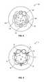
- FIG. 5a cross section through a displacement unit according to a fourth example of an embodiment of the invention.
- a displacement unit 1with an inner part 2 and outer part 3 that is coaxial to it is shown.
- six inner paths 4are designed which extend essentially parallel to one another in axial direction. Thereby, two inner paths 4 are always arranged in pairs with respect to one another whereby between the inner pairs of paths a distance section remains on the outer surface of inner part 2 , which is designed essentially cylindrical.
- outer paths 5are provided that run parallel to one another in axial direction.
- the outer paths 5are also associated with one another in pairs and are distributed over the circumference of outer part 3 in such a way that respectively one outer path 5 is opposite to an inner path 4 and together with it forms a pair of paths.
- At least one ball 6is respectively accepted for transmitting torque between inner part 2 and outer part 3 .
- the inner part 2is thereby displaceable in axial direction relative to the outer part 3 , whereby balls 6 roll in inner paths 4 and outer paths 5 .
- the displacement unit 1When the displacement unit 1 is designed as a roller balance, several balls 6 are provided in every pair of paths so that inner part 2 cannot be tipped or swiveled relative to outer part 3 . If, on the other hand, the displacement unit 1 is designed as a displacement joint, one ball 6 is provided in each pair of paths so that the inner part 2 can be bent at least by a small angle with respect to outer part 3 .
- Balls 6are accepted in windows of cage 7 and guided in it.
- cage 7is guided in outer part 3 in axial direction.
- cage guide paths 8are formed in the inner surface of outer part 3 , with which cage guide protrusions 9 of cage 7 engage.
- the cage guide pathscan, however, also be provided in the inner part.
- cage guide paths 8which can, for example, have a rectangular cross section, are provided in the section between two pairs of paths that are associated with one another. Consequently, between two cage guide paths 8 , there are always two outer paths 5 . Cage guide paths 8 and outer paths 5 are thereby at least essentially evenly distributed over the circumference of outer part 3 . Hereby, deformation as a result of hardening in outer part 3 can be avoided. Further, it is then also possible to design outer part 3 as a sheet metal part with walls that are essentially of constant thickness.
- a displacement unit 10is shown as per a second embodiment, which is also provided with an—to an axis 11 —coaxial inner part 12 and hereto a coaxial outer part 13 .
- inner part 12there are provided in turn, inner paths 14 and in outer part 13 outer paths 15 that are associated with one another and that form pairs of paths.
- inner paths 14 and in outer part 13outer paths 15 that are associated with one another and that form pairs of paths.
- ball 16is accepted which is guided in a cage 17 .
- Displacement unit 10is designed with six pairs of paths and four cage guide path in outer part 13 , deviating from the representation of the embodiment as per FIG. 1 . Additionally, cage guide paths are also formed in inner part 12 .
- cage guide paths 18with which cage guide protrusions 19 engage.
- Cage guide protrusions 19 and cage guide paths 18are thereby designed triangular in cross section in the embodiment as per FIG. 2 .
- the cage guide paths and the cage guide protrusionscan, however, be provided with suitable contours and can be, for example, rounded or the like.
- FIG. 4illustrates a cage path arrangement comprising rounded contours.
- the cageWhen the cage is made of plastic, it can be provided with guide protrusions that engage the cage guide paths, which are, for example, rounded or angular.
- FIG. 5illustrates a plastic cage arrangement with a cross hatch pattern to depict plastic material.
- the cageis a formed piece of sheet metal or a piece of tube with walls that are essentially of constant thickness, whereby, (cage) guide protrusions are provided that engage with the cage guide paths.
- the cageis a folding cage with cage guide pins which do not engage with the pairs of paths but with the cage guide paths.
- cage guide paths 18 and the corresponding cage guide protrusions 19 with the inner part 12 as well as the outer part 13can, according to the invention, be provided either only in inner part 12 or only in outer part 13 .
- FIG. 3shows a longitudinal shaft 20 in longitudinal cross section that is designed as a longitudinal shaft for a vehicle, which is provided with two displacement units 21 and 22 that are designed as rolling adjustments.
- the universal shaft 20is illustrated and a first flute tube 31 provided adjacent and on the left side of the intermediate bearing 26 and a second flute tube 32 provided adjacent and on the right hand side of the middle joint 25 .
- the universal shaft 20is respectively designed with a fixed joint 23 or 24 and has a middle joint 25 in the middle, which is also a fixed joint.
- the two rolling adjustments 21 and 22are thereby associated with the middle joint 25 , whereby the inner part of the second rolling adjustment 22 is connected with the inner race of the middle joint 25 and the inner part of the first rolling adjustment 21 is connected with the outer race of the middle joint 25 . Further, the inner race of the first rolling adjustment 21 is mounted in an intermediate bearing 26 which can, for example be hung resiliently on the bottom of a vehicle.
- the outer parts of the two roller balances 21 and 22are connected with tubular shafts which are attached to the outer race of joint 23 , 24 on the side of the gear or on the differential side.
- the universal shaft 20is thereby formed by three fixed joints and two roller balances which are associated with the middle joint 25 .
- the axially required displacement paths of universal shaft 20 in operation and particularly during assemblycan only be accepted by roller balances 21 and 22 .
Landscapes
- Engineering & Computer Science (AREA)
- General Engineering & Computer Science (AREA)
- Mechanical Engineering (AREA)
- Shafts, Cranks, Connecting Bars, And Related Bearings (AREA)
- Bearings For Parts Moving Linearly (AREA)
- Motor Power Transmission Devices (AREA)
- Rolling Contact Bearings (AREA)
- Machine Tool Units (AREA)
Abstract
Description
Claims (11)
Applications Claiming Priority (4)
| Application Number | Priority Date | Filing Date | Title |
|---|---|---|---|
| DE102006038697 | 2006-08-18 | ||
| DE102006038697.3 | 2006-08-18 | ||
| DE102006038697 | 2006-08-18 | ||
| PCT/DE2007/001442WO2008019668A1 (en) | 2006-08-18 | 2007-08-16 | Displacement unit and universal shaft comprising a displacement unit |
Publications (2)
| Publication Number | Publication Date |
|---|---|
| US20100227696A1 US20100227696A1 (en) | 2010-09-09 |
| US8328649B2true US8328649B2 (en) | 2012-12-11 |
Family
ID=38787595
Family Applications (1)
| Application Number | Title | Priority Date | Filing Date |
|---|---|---|---|
| US12/377,600Expired - Fee RelatedUS8328649B2 (en) | 2006-08-18 | 2007-08-16 | Displacement unit and universal shaft comprising a displacement unit |
Country Status (7)
| Country | Link |
|---|---|
| US (1) | US8328649B2 (en) |
| JP (1) | JP2010501058A (en) |
| CN (1) | CN101506537B (en) |
| DE (1) | DE112007002502A5 (en) |
| FR (1) | FR2904989B1 (en) |
| IT (1) | ITMI20071673A1 (en) |
| WO (1) | WO2008019668A1 (en) |
Cited By (5)
| Publication number | Priority date | Publication date | Assignee | Title |
|---|---|---|---|---|
| US11028883B2 (en) | 2017-11-13 | 2021-06-08 | Arctic Cat Inc. | Off-road recreational vehicle |
| US20220163068A1 (en)* | 2019-01-28 | 2022-05-26 | Erae Ams Co., Ltd | Plunging shaft and drive shaft assembly including same |
| US11712925B2 (en) | 2019-07-01 | 2023-08-01 | Textron Inc. | Axial plunging half-shaft assembly |
| US11766932B2 (en) | 2015-08-23 | 2023-09-26 | Arctic Cat Inc. | Off road vehicle |
| US11787279B2 (en) | 2015-08-23 | 2023-10-17 | Arctic Cat Inc. | Off-road recreational vehicle |
Families Citing this family (5)
| Publication number | Priority date | Publication date | Assignee | Title |
|---|---|---|---|---|
| GB2444200B (en)* | 2005-09-27 | 2010-11-24 | Shaft Form Engineering Gmbh | Displacement unit and joint shaft comprising a displacement unit |
| EP2166239B1 (en)* | 2008-09-18 | 2012-04-18 | Centa-Antriebe Kirschey GmbH | Shaft assembly for transferring torque |
| US9958015B2 (en)* | 2013-09-27 | 2018-05-01 | Steering Solutions Ip Holding Corporation | Rolling-element telescoping shaft assembly |
| FR3081197B1 (en)* | 2018-05-15 | 2021-12-10 | Safran Aircraft Engines | REDUCED FRICTION TORQUE TRANSMISSION DEVICE |
| CN114653072B (en)* | 2022-04-06 | 2023-12-12 | 广东派儿格智能科技有限公司 | Transmission device and toy car |
Citations (7)
| Publication number | Priority date | Publication date | Assignee | Title |
|---|---|---|---|---|
| JPH0297719A (en) | 1988-03-17 | 1990-04-10 | Loehr & Bromkamp Gmbh | Synchronous sliding joint |
| DE19831016A1 (en) | 1998-07-10 | 2000-01-20 | Gkn Loebro Gmbh | Propeller shaft assembly for connecting a gearbox to a rear axle drive of a vehicle |
| DE19952245A1 (en) | 1998-12-05 | 2000-07-06 | Gkn Loebro Gmbh | Telescopic shaft for connecting two joints of a driveshaft, consists an outer part, inner part and a cage holding balls |
| DE20317344U1 (en) | 2003-11-11 | 2004-01-08 | Dura Automotive Systems Reiche Gmbh & Co. Kg | Telescopic steering shaft |
| DE10237169A1 (en) | 2002-08-14 | 2004-03-04 | Werner Jacob | Plunging joint |
| US20040214647A1 (en) | 2002-07-25 | 2004-10-28 | Hans-Heinrich Welschof | Longitudinal displacement unit with braking rollers |
| US20080248886A1 (en)* | 2005-09-27 | 2008-10-09 | Shaft-Form Emgineering Gmbh | Joint Shaft and Roller Displacement |
Family Cites Families (5)
| Publication number | Priority date | Publication date | Assignee | Title |
|---|---|---|---|---|
| JPH0428220U (en)* | 1990-06-29 | 1992-03-06 | ||
| JP4034356B2 (en)* | 1996-10-31 | 2008-01-16 | ジー・ケー・エヌ・ドライブライン・インターナショナル・ゲゼルシャフト・ミット・ベシュレンクテル・ハフツング | Constant velocity universal joint |
| DE59909689D1 (en)* | 1998-01-19 | 2004-07-15 | Thyssenkrupp Presta Ag Eschen | DOUBLE JOINT FOR STEERING SHAFT IN MOTOR VEHICLES |
| US6059665A (en)* | 1998-06-08 | 2000-05-09 | The United States Of America As Represented By The Secretary Of The Air Force | Linear ball bearing drive shaft |
| CN2563352Y (en)* | 2002-07-22 | 2003-07-30 | 浙江万向机械有限公司 | Constant relocity universal joint with illiptic groove |
- 2007
- 2007-08-13ITIT001673Apatent/ITMI20071673A1/enunknown
- 2007-08-16CNCN2007800305915Apatent/CN101506537B/ennot_activeExpired - Fee Related
- 2007-08-16JPJP2009524073Apatent/JP2010501058A/enactivePending
- 2007-08-16USUS12/377,600patent/US8328649B2/ennot_activeExpired - Fee Related
- 2007-08-16WOPCT/DE2007/001442patent/WO2008019668A1/enactiveApplication Filing
- 2007-08-16DEDE112007002502Tpatent/DE112007002502A5/ennot_activeWithdrawn
- 2007-08-17FRFR0757085Apatent/FR2904989B1/ennot_activeExpired - Fee Related
Patent Citations (14)
| Publication number | Priority date | Publication date | Assignee | Title |
|---|---|---|---|---|
| JPH0297719A (en) | 1988-03-17 | 1990-04-10 | Loehr & Bromkamp Gmbh | Synchronous sliding joint |
| US5026325A (en) | 1988-03-17 | 1991-06-25 | Lohr & Bromkamp Gmbh | Constant velocity ratio plunging universal joint |
| DE19831016A1 (en) | 1998-07-10 | 2000-01-20 | Gkn Loebro Gmbh | Propeller shaft assembly for connecting a gearbox to a rear axle drive of a vehicle |
| US6241617B1 (en)* | 1998-07-10 | 2001-06-05 | Gkn Lobro Gmbh | Propeller shaft assembly for a motor vehicle especially a passenger car |
| DE19952245A1 (en) | 1998-12-05 | 2000-07-06 | Gkn Loebro Gmbh | Telescopic shaft for connecting two joints of a driveshaft, consists an outer part, inner part and a cage holding balls |
| US6217456B1 (en) | 1998-12-05 | 2001-04-17 | Gkn Lobro Gmbh | Telescopic shaft |
| US6902487B2 (en)* | 2002-07-25 | 2005-06-07 | Gkn Driveline Deutschland Gmbh | Longitudinal displacement unit with braking rollers |
| US20040214647A1 (en) | 2002-07-25 | 2004-10-28 | Hans-Heinrich Welschof | Longitudinal displacement unit with braking rollers |
| DE10237169A1 (en) | 2002-08-14 | 2004-03-04 | Werner Jacob | Plunging joint |
| US20060166749A1 (en) | 2002-08-14 | 2006-07-27 | Werner Jacob | Sliding articulation |
| DE20317344U1 (en) | 2003-11-11 | 2004-01-08 | Dura Automotive Systems Reiche Gmbh & Co. Kg | Telescopic steering shaft |
| US7290800B2 (en) | 2003-11-11 | 2007-11-06 | Dura Automotive Systems Reich Gmbh | Telescoping steering shaft |
| US20080248886A1 (en)* | 2005-09-27 | 2008-10-09 | Shaft-Form Emgineering Gmbh | Joint Shaft and Roller Displacement |
| US7670229B2 (en)* | 2005-09-27 | 2010-03-02 | Shaft-Form-Engineering Gmbh | Displacement unit and joint shaft including such a displacement unit |
Non-Patent Citations (2)
| Title |
|---|
| English Translation of the Japanese Office Action, Notification of Reasons for Rejection. |
| Wagner, E. R., "Driveline and Driveshaft Arrangements and Constructions," Universal Joint and Driveshaft Design Manual, AE-7, Society of Automotive Engineers, Inc., Warrendale, PA, pp. 3-10, TJ1079.S62 1979.* |
Cited By (11)
| Publication number | Priority date | Publication date | Assignee | Title |
|---|---|---|---|---|
| US11766932B2 (en) | 2015-08-23 | 2023-09-26 | Arctic Cat Inc. | Off road vehicle |
| US11787279B2 (en) | 2015-08-23 | 2023-10-17 | Arctic Cat Inc. | Off-road recreational vehicle |
| US12351027B2 (en) | 2015-08-23 | 2025-07-08 | Arctic Cat Inc. | Off-road recreational vehicle |
| US12358367B2 (en) | 2015-08-23 | 2025-07-15 | Arctic Cat Inc. | Off road vehicle |
| US11028883B2 (en) | 2017-11-13 | 2021-06-08 | Arctic Cat Inc. | Off-road recreational vehicle |
| US11802593B2 (en) | 2017-11-13 | 2023-10-31 | Arctic Cat Inc. | Off-road recreational vehicle |
| US12117048B2 (en) | 2017-11-13 | 2024-10-15 | Arctic Cat Inc. | Off-road recreational vehicle |
| US20220163068A1 (en)* | 2019-01-28 | 2022-05-26 | Erae Ams Co., Ltd | Plunging shaft and drive shaft assembly including same |
| US12031594B2 (en)* | 2019-01-28 | 2024-07-09 | Erae Ams Co., Ltd | Plunging shaft and drive shaft assembly including same |
| US11712925B2 (en) | 2019-07-01 | 2023-08-01 | Textron Inc. | Axial plunging half-shaft assembly |
| US12208644B2 (en) | 2019-07-01 | 2025-01-28 | Textron Inc. | Axial plunging half-shaft assembly |
Also Published As
| Publication number | Publication date |
|---|---|
| CN101506537A (en) | 2009-08-12 |
| FR2904989A1 (en) | 2008-02-22 |
| DE112007002502A5 (en) | 2009-07-23 |
| US20100227696A1 (en) | 2010-09-09 |
| JP2010501058A (en) | 2010-01-14 |
| WO2008019668A1 (en) | 2008-02-21 |
| FR2904989B1 (en) | 2014-02-14 |
| CN101506537B (en) | 2012-10-03 |
| ITMI20071673A1 (en) | 2008-02-19 |
Similar Documents
| Publication | Publication Date | Title |
|---|---|---|
| US8328649B2 (en) | Displacement unit and universal shaft comprising a displacement unit | |
| US6234908B1 (en) | Drive assembly with at least one constant velocity fixed joint having a set of rolling contact member guiding means | |
| KR20120023789A (en) | Plunging cross-track constant velocity joint | |
| JP2000192937A (en) | Extensible shaft | |
| US8118683B2 (en) | Joint shaft and roller displacement UNIT THEREFOR | |
| DE19938771C2 (en) | PTO shaft with adaptation to a preferred torque transmission direction | |
| US20040197037A1 (en) | Roller bearing for linear movements | |
| EP0608339A4 (en) | Anti-shudder tripod constant velocity joint. | |
| CN101578458B (en) | constant velocity sliding joint | |
| US7544132B2 (en) | Constant-velocity fixed joint | |
| EP2831437B1 (en) | Constant velocity joint | |
| US11835096B2 (en) | Plunging type constant velocity universal joint for propeller shaft | |
| US11359677B2 (en) | Plunging type constant velocity universal joint for rear-wheel drive shaft | |
| JP2009507196A (en) | Joint shaft with counter track joint with limited axial travel | |
| US20070275784A1 (en) | Twin-ball joint | |
| CN108700126A (en) | Roller for ball-and-pin universal joint | |
| US20180363712A1 (en) | Ball cage for cross-groove type plunging and fixed constant velocity joints | |
| EP1685332A1 (en) | Constant velocity joint with inclined ball tracks | |
| US8348771B2 (en) | Cross shaft member and cross shaft joint with the same | |
| US20170138407A1 (en) | Sliding ball joint having crossing raceways having a different angle of inclination and a minimum radial distance | |
| CN110431324A (en) | Sliding constant speed universal coupling for rear-wheel drive shaft | |
| US7922593B2 (en) | Driveshaft assembly | |
| KR20200014766A (en) | Double Row Angular Contact Ball Bearing | |
| CN106555824A (en) | A kind of rzeppa joint, card gear and automobile | |
| US20150377302A1 (en) | Universal joint bearing, joint cross, universal joint, and multi-row needle roller bearing |
Legal Events
| Date | Code | Title | Description |
|---|---|---|---|
| AS | Assignment | Owner name:SHAFT-FORM-ENGINEERING GMBH, GERMANY Free format text:ASSIGNMENT OF ASSIGNORS INTEREST;ASSIGNOR:DISSER, CLAUS;REEL/FRAME:029266/0050 Effective date:20090331 | |
| STCF | Information on status: patent grant | Free format text:PATENTED CASE | |
| AS | Assignment | Owner name:BF NEW TECHNOLOGIES GMBH, GERMANY Free format text:ASSIGNMENT OF ASSIGNORS INTEREST;ASSIGNOR:SHAFT-FORM-ENGINEERING GMBH;REEL/FRAME:038402/0524 Effective date:20090120 | |
| AS | Assignment | Owner name:BHARAT FORGE GLOBAL HOLDING GMBH, GERMANY Free format text:MERGER AND CHANGE OF NAME;ASSIGNORS:BF NEW TECHNOLOGIES GMBH;BHARAT FORGE GLOBAL HOLDING GMBH;REEL/FRAME:038596/0310 Effective date:20151106 | |
| FPAY | Fee payment | Year of fee payment:4 | |
| FEPP | Fee payment procedure | Free format text:MAINTENANCE FEE REMINDER MAILED (ORIGINAL EVENT CODE: REM.); ENTITY STATUS OF PATENT OWNER: LARGE ENTITY | |
| LAPS | Lapse for failure to pay maintenance fees | Free format text:PATENT EXPIRED FOR FAILURE TO PAY MAINTENANCE FEES (ORIGINAL EVENT CODE: EXP.); ENTITY STATUS OF PATENT OWNER: LARGE ENTITY | |
| STCH | Information on status: patent discontinuation | Free format text:PATENT EXPIRED DUE TO NONPAYMENT OF MAINTENANCE FEES UNDER 37 CFR 1.362 | |
| FP | Lapsed due to failure to pay maintenance fee | Effective date:20201211 |