US8328170B2 - Clamping apparatus - Google Patents
Clamping apparatusDownload PDFInfo
- Publication number
- US8328170B2 US8328170B2US12/488,513US48851309AUS8328170B2US 8328170 B2US8328170 B2US 8328170B2US 48851309 AUS48851309 AUS 48851309AUS 8328170 B2US8328170 B2US 8328170B2
- Authority
- US
- United States
- Prior art keywords
- handle
- magnet
- release lever
- clamping apparatus
- movable jaw
- Prior art date
- Legal status (The legal status is an assumption and is not a legal conclusion. Google has not performed a legal analysis and makes no representation as to the accuracy of the status listed.)
- Expired - Fee Related, expires
Links
- 238000004519manufacturing processMethods0.000description4
- 238000000034methodMethods0.000description4
- 238000003466weldingMethods0.000description3
- 229910052751metalInorganic materials0.000description2
- 239000002184metalSubstances0.000description2
- 229910000831SteelInorganic materials0.000description1
- 229910052782aluminiumInorganic materials0.000description1
- XAGFODPZIPBFFR-UHFFFAOYSA-NaluminiumChemical compound[Al]XAGFODPZIPBFFR-UHFFFAOYSA-N0.000description1
- -1but not limited toSubstances0.000description1
- 238000010276constructionMethods0.000description1
- 230000008878couplingEffects0.000description1
- 238000010168coupling processMethods0.000description1
- 238000005859coupling reactionMethods0.000description1
- 239000000463materialSubstances0.000description1
- 229910001092metal group alloyInorganic materials0.000description1
- 238000012986modificationMethods0.000description1
- 230000004048modificationEffects0.000description1
- 238000003825pressingMethods0.000description1
- 230000006641stabilisationEffects0.000description1
- 238000011105stabilizationMethods0.000description1
- 239000010959steelSubstances0.000description1
- 238000003860storageMethods0.000description1
Images


Classifications
- B—PERFORMING OPERATIONS; TRANSPORTING
- B25—HAND TOOLS; PORTABLE POWER-DRIVEN TOOLS; MANIPULATORS
- B25B—TOOLS OR BENCH DEVICES NOT OTHERWISE PROVIDED FOR, FOR FASTENING, CONNECTING, DISENGAGING OR HOLDING
- B25B7/00—Pliers; Other hand-held gripping tools with jaws on pivoted limbs; Details applicable generally to pivoted-limb hand tools
- B25B7/12—Pliers; Other hand-held gripping tools with jaws on pivoted limbs; Details applicable generally to pivoted-limb hand tools involving special transmission means between the handles and the jaws, e.g. toggle levers, gears
- B25B7/123—Pliers; Other hand-held gripping tools with jaws on pivoted limbs; Details applicable generally to pivoted-limb hand tools involving special transmission means between the handles and the jaws, e.g. toggle levers, gears with self-locking toggle levers
- B—PERFORMING OPERATIONS; TRANSPORTING
- B25—HAND TOOLS; PORTABLE POWER-DRIVEN TOOLS; MANIPULATORS
- B25B—TOOLS OR BENCH DEVICES NOT OTHERWISE PROVIDED FOR, FOR FASTENING, CONNECTING, DISENGAGING OR HOLDING
- B25B7/00—Pliers; Other hand-held gripping tools with jaws on pivoted limbs; Details applicable generally to pivoted-limb hand tools
- B25B7/02—Jaws
- B—PERFORMING OPERATIONS; TRANSPORTING
- B25—HAND TOOLS; PORTABLE POWER-DRIVEN TOOLS; MANIPULATORS
- B25B—TOOLS OR BENCH DEVICES NOT OTHERWISE PROVIDED FOR, FOR FASTENING, CONNECTING, DISENGAGING OR HOLDING
- B25B7/00—Pliers; Other hand-held gripping tools with jaws on pivoted limbs; Details applicable generally to pivoted-limb hand tools
- B25B7/14—Locking means
Definitions
- the present disclosurerelates generally to the field of clamping apparatus, and more specifically, to securing clamping apparatus in a clamping position.
- a clamping apparatusmay be a type of tool used in the manufacturing industry to hold and move parts during the building or assembly process.
- Various types of clamping apparatusincluding clamps and pliers, may be utilized in the automotive manufacturing process, for example, to clamp heavy objects, such as axles of an automobile, while on a manufacturing assembly.
- Some clamping apparatusmay include a locking device such as a toggle, for example, to secure a part within the clamping apparatus.
- a locking devicesuch as a toggle
- current locking devicesmay not provide for extra stabilization when a relatively heavy object, such as an axle on an automotive assembly line, is being clamped.
- current locking devices on clamping apparatusmay not provide an efficient means for a user to secure a clamping apparatus in a clamping position or release such an apparatus from the clamping position to an open position.
- a clamping apparatusincluding a first handle defining a hole, a magnet affixed to the first handle, and a movable jaw coupled to the first handle and a second handle, the jaw comprising two clamp segments.
- the apparatusfurther includes a magnet contacting element disposed on a release lever on the second handle, wherein pressure is applied to release the release lever from contacting the magnet in an open position.
- a clamping apparatusincluding a first handle defining a hole, a magnet affixed to the first handle to secure the clamping apparatus in a clamping position, and a movable jaw coupled to the first handle, the jaw comprising two clamp segments, wherein each of the two clamp segments comprise an end portion with a substantially semi-circular cross-sectional surface.
- the clamping apparatusfurther includes a release lever coupled to the movable jaw, the release lever in contact with the magnet in the clamping position and wherein pressure is applied to release the release lever from contacting the magnet in an open position.
- a further aspect of the present disclosureprovides for a clamping apparatus including a first handle defining a hole, a magnet affixed to the first handle, and a movable jaw coupled to the first handle and a second handle, the jaw comprising two clamp segments.
- the clamping apparatusfurther includes a magnet contacting element disposed on a release lever on the second handle, wherein the magnet contacting element is engaged with the magnet to secure the clamping apparatus in a clamping position.
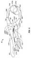
- FIG. 1represents an isometric view of a clamping apparatus in accordance with one aspect of the present disclosure
- FIG. 2represents a view of the clamping apparatus of FIG. 1 in an open position
- FIG. 3represents a view of the clamping apparatus of FIG. 1 in a clamped position.
- FIG. 1represents an isometric view of a clamping apparatus, generally indicated at 5 , in accordance with one aspect of the present disclosure.
- the clamping apparatus 5may be made of suitable rigid material including, but not limited to, metal, metal alloy, steel, aluminum, or the like.
- the clamping apparatus 5may include a handle 10 coupled to a release lever 50 and a movable jaw 40 comprising clamp segments 80 a , 80 b . It should be understood that the present disclosure has applicability to clamping apparatus 5 as broadly described herein, and is not intended to be limited to the clamping apparatus 5 or its elements specifically described.
- the handle 10includes an elongated body which provides a surface onto which the palm of a user may contact and/or grip the clamping apparatus 5 .
- the handle 10may define additional features such as grooves or elements to facilitate the gripping of the clamping apparatus 5 , which may not be shown in FIG. 1 .
- the handle 10may be pivotally fixed to the movable jaw 40 via a connecting means such as fasteners 160 b - 160 e .
- An elastic member 130may further interconnect the handle 10 to the movable jaw 40 , providing a means for which the handle 10 can move relative to a release lever 50 or secondary handle 70 (to be described below) from a first position, such as an open position, to a second position, such as a clamping position.
- a magnet 30Disposed on the handle 10 , as seen in FIG. 1 , or any suitable location on the clamping apparatus 5 is a magnet 30 .
- the magnet 30provides a means for the handle 10 to be in contact with an element of the clamping apparatus 5 , including a magnet contacting element 60 , a release lever 50 or a secondary handle 70 , such as to secure the clamping apparatus 5 in a clamping position, as shown in FIG. 3 .
- the clamping apparatus 5may be in a “clamping position” when end portions 100 a , 100 b of clamping segments 80 a , 80 b (to be discussed in detail below) are in proximity to one another to grip, hold, and/or secure an object.
- the magnet 30may assume any conventional shape or orientation to be in contact with another portion of the clamping apparatus 5 to secure the clamping apparatus 5 in a clamping position. As shown, the magnet 30 is fixed on the inward surface of the handle 10 of the clamping apparatus 5 . However, the present disclosure contemplates a magnet 30 located anywhere on the clamping apparatus 5 in order to contact any portion of the clamping apparatus 5 while in the clamping position.
- the magnetmay be formed as part of the handle 10 or it may be fixed to the handle 10 by any suitable means such as by welding, adhesion, or similar fixing means.
- magnetic forcemay maintain the clamping apparatus 5 in a clamped (i.e., locked) position until it is manually opened by applying pressure to the release lever 50 .
- the additional security provided by the magnetmay allow the clamping apparatus 5 of the present disclosure to securely hold and/or grip relatively heavy objects such as metal rods and axles.
- the clamping apparatus 5is depicted in an open position, in accordance with one aspect of the present disclosure.
- the magnet 30is not in contact with the magnet contacting element 60 , release lever 50 , secondary handle 70 , or any other portion of the clamping apparatus 5 .
- the open position of the clamping apparatus 5is characterized by the end portions 100 a , 100 b of the clamp segments 80 a , 80 b being at a distance from each other so as to prevent the holding or gripping of an object by the end portions 100 a , 100 b .
- the secondary handle 70may be coupled, similarly to the handle 10 , to the movable jaw 40 via a fastener 160 b .
- movement of the secondary handle 70may cause the movable jaw 40 to open or close.
- the movable jaw 40opens when the clamping apparatus 5 moves towards the open position whereas the movable jaw 40 closes when the clamping apparatus 5 moves toward the clamped position.
- the secondary handle 70may provide a magnet contacting element 60 directly on the secondary handle 70 or on the release lever 50 (described below), as shown, which is coupled to the secondary handle 70 via a lever linking element 150 .
- the magnet contacting element 60may be located on a protruding element as depicted in FIG. 2 .
- the magnet contacting element 60may exist on the flat surface of the release lever 50 , secondary handle 70 or other portion of the clamping apparatus 5 to be contacted with the magnet 30 .
- the magnet contacting element 60as a protruding element, may be fixed on the inward surface of the secondary handle 70 of the clamping apparatus 5 .
- the release lever 50may provide a means to disengage contact between the magnet 30 and magnet contacting element 60 , such as in the closed position.
- the release lever 50may be of a type generally known to those skilled in the art of handheld tools. Pressure may be applied to the end tip of the release lever 50 to release contact between the magnet 30 and magnet contacting element 60 .
- an elastic member(not shown), such as a spring, may couple the release lever 50 to an internal cavity of the secondary handle 70 .
- the release lever 50is at closer proximity to the magnet 30 as compared to the secondary handle 70 and thus provides more easy in contacting the magnet 30 to a magnet contacting element 60 disposed on the secondary handle 70 .
- a linking element 110may provide a means of coupling the handle 10 to the secondary handle 70 to allow movement of the secondary handle 70 . Movement of the secondary handle 70 may in turn effectuate movement of the movable jaw 40 from a closed position to an open position, and vice versa.
- the linking element 110may be coupled to the handle 10 and/or the secondary handle 70 via connecting means such as fastener 160 a .
- the linking element 110may provide a means to lock movement of the secondary handle 70 , such as when the clamping apparatus is in the open position.
- a locking lever(not shown) in an internal cavity of the handle 10 or secondary handle 70 may prevent the movement or and lock the secondary handle 70 in place.
- the internal cavity of the handle 10 or secondary handle 70may define at least one groove (not shown) into which the linking element 110 may reside to prevent movement of the secondary handle 70 .
- the linking element 110may also enable the locking of the movable jaw 40 . Further, the linking element 110 may collapse into the internal cavity of the secondary handle 70 to efficiently move the clamping apparatus 5 to a clamping position.
- the movable jaw 40may comprise two clamp segments 80 a , 80 b .
- the clamp segments 80 a , 80 bmay be portions of the movable jaw 40 or they may be separate elements coupled to the movable jaw 40 via hinges 75 a , 75 b .
- an additional hinge fastener(not shown) may be utilized to lock movement of the hinges 75 a , 75 b .
- the hinge fastenermay allow the clamp segments 80 a , 80 b to be pivoted at angles less than or greater than the angle of the movable jaw 40 and thus, allow versatility in the size of objects that can be held within the end portions 100 a , 100 b .
- the movable jaw 40 and clamp segments 80 a , 80 bare formed from the same piece, i.e., without the hinges 75 a , 75 b , the movable jaw 40 and clamp segments 80 a , 80 b maintain a rigid and fixed form.
- the end portions 100 a , 100 bprovide contact between the clamping apparatus 5 and a held object (not shown).
- the end portions 100 a , 100 bmay have a substantially semi-circular or semi-cylindrical cross-section, as shown in FIGS. 1-3 . However, it is understood that the end portions 100 a , 100 b may have any conventional cross-sectional shape suitable to hold a particular object.
- the outer surface portions 90 a , 90 bare the surfaces not in contact with the object when it clamped by the clamping apparatus 5 .
- the end portions 100 a , 100 b and the outer surface portions 90 a , 90 bform a shaft support collar capable of clamping around a particular object by an inward movement of the handle 10 and secondary handle 70 .
- the shaft support collarmay be formed from the same pieces as the clamp segments 80 a , 80 b or it may be a separate portion of the clamping apparatus 5 affixed by any reasonable means such as welding, fastening (e.g., via screws, nuts, bolts) or the like.
- a loop portion 20is Also coupled to or formed from the handle 10 .
- the loop portion 20serves as a means to hang the clamping apparatus 5 for ease of access, storage or display when not in use.
- any reasonable means of fixing the loop portion 20 to the handle 10may be contemplated such as by welding, fastening (e.g., via nut, bolt), or the like.
- an end of the loop portion 20may be affixed to the handle 10 still allowing extension of the loop portion 20 (e.g., via wire) to allow hanging of the clamping apparatus 5 when not in use.
- the adjustment component 120may comprise a threaded screw engaged on the terminal end of the handle 10 within a threaded aperture.
- the end of the screwmay be engaged with a toggle link. By rotating the screw, the position of the toggle link may be altered, thereby providing more or less relative force between the handle 10 and the movable jaw 40 .
- the adjustment component 120may alter the level of tightness or looseness of the movement of the secondary handle 70 and/or moveable jaw 40 .
- Elements of the present disclosuremay include a magnet to secure the clamping apparatus in a clamping position while a release lever provides an efficient means to release the clamping apparatus from a clamping to an open position.
- clamping apparatus of the present disclosuremay provide efficiency in securely gripping heavy objects, particularly during an assembly process.
Landscapes
- Engineering & Computer Science (AREA)
- Mechanical Engineering (AREA)
- Clamps And Clips (AREA)
Abstract
Description
Claims (20)
Priority Applications (1)
| Application Number | Priority Date | Filing Date | Title |
|---|---|---|---|
| US12/488,513US8328170B2 (en) | 2009-06-19 | 2009-06-19 | Clamping apparatus |
Applications Claiming Priority (1)
| Application Number | Priority Date | Filing Date | Title |
|---|---|---|---|
| US12/488,513US8328170B2 (en) | 2009-06-19 | 2009-06-19 | Clamping apparatus |
Publications (2)
| Publication Number | Publication Date |
|---|---|
| US20100320663A1 US20100320663A1 (en) | 2010-12-23 |
| US8328170B2true US8328170B2 (en) | 2012-12-11 |
Family
ID=43353573
Family Applications (1)
| Application Number | Title | Priority Date | Filing Date |
|---|---|---|---|
| US12/488,513Expired - Fee RelatedUS8328170B2 (en) | 2009-06-19 | 2009-06-19 | Clamping apparatus |
Country Status (1)
| Country | Link |
|---|---|
| US (1) | US8328170B2 (en) |
Cited By (22)
| Publication number | Priority date | Publication date | Assignee | Title |
|---|---|---|---|---|
| US20140208898A1 (en)* | 2013-01-27 | 2014-07-31 | Robert Bosch Gmbh | Locking Plier Jaws |
| US20150143955A1 (en)* | 2013-11-26 | 2015-05-28 | Wolff Industries, Inc. | Conditioning Device for Conditioning a Blade |
| US9445863B2 (en) | 2013-03-15 | 2016-09-20 | Gyrus Acmi, Inc. | Combination electrosurgical device |
| US9452011B2 (en) | 2013-03-15 | 2016-09-27 | Gyrus Acmi, Inc. | Combination electrosurgical device |
| US20170043456A1 (en)* | 2015-08-10 | 2017-02-16 | Westek Electronics, Inc. | Multi-functional clamping device |
| US9707028B2 (en) | 2014-08-20 | 2017-07-18 | Gyrus Acmi, Inc. | Multi-mode combination electrosurgical device |
| US9763730B2 (en) | 2013-03-15 | 2017-09-19 | Gyrus Acmi, Inc. | Electrosurgical instrument |
| US9782216B2 (en) | 2015-03-23 | 2017-10-10 | Gyrus Acmi, Inc. | Medical forceps with vessel transection capability |
| US20170348830A1 (en)* | 2016-06-01 | 2017-12-07 | Leatherman Tool Group, Inc. | Multipurpose tool having accessible tool members |
| US9901389B2 (en) | 2013-03-15 | 2018-02-27 | Gyrus Acmi, Inc. | Offset forceps |
| US9901388B2 (en) | 2013-03-15 | 2018-02-27 | Gyrus Acmi, Inc. | Hand switched combined electrosurgical monopolar and bipolar device |
| US10667834B2 (en) | 2017-11-02 | 2020-06-02 | Gyrus Acmi, Inc. | Bias device for biasing a gripping device with a shuttle on a central body |
| US10786299B2 (en) | 2018-03-30 | 2020-09-29 | Gyrus Acmi, Inc. | Closure assembly that is laterally movable for selective locking |
| US10842516B2 (en) | 2018-04-30 | 2020-11-24 | Gyrus Acmi, Inc. | Forceps including a pre-loaded handle latch |
| US10849682B2 (en) | 2018-03-30 | 2020-12-01 | Gyrus Acmi, Inc. | Forceps including a double biased handle latch |
| US10849641B2 (en) | 2018-03-30 | 2020-12-01 | Gyrus Acmi, Inc. | Forceps including a pre-loaded handle latch |
| US10926396B2 (en) | 2018-06-19 | 2021-02-23 | Leatherman Tool Group, Inc. | Tool having one or more rotatable tool members |
| US11298801B2 (en) | 2017-11-02 | 2022-04-12 | Gyrus Acmi, Inc. | Bias device for biasing a gripping device including a central body and shuttles on the working arms |
| US11383373B2 (en) | 2017-11-02 | 2022-07-12 | Gyms Acmi, Inc. | Bias device for biasing a gripping device by biasing working arms apart |
| US20220226980A1 (en)* | 2021-01-15 | 2022-07-21 | Ingersoll-Rand Industrial U.S., Inc. | Auxiliary handle for a power tool |
| US20230347485A1 (en)* | 2022-04-29 | 2023-11-02 | Canadian Tire Corporation, Limited | Oil filter removal tool |
| US12420383B1 (en)* | 2025-01-03 | 2025-09-23 | Mark Dean Munson | Offset vise tool |
Families Citing this family (5)
| Publication number | Priority date | Publication date | Assignee | Title |
|---|---|---|---|---|
| US9048571B2 (en)* | 2012-08-29 | 2015-06-02 | Charles E Hicks | Grounding device for welders |
| US9962820B2 (en)* | 2013-12-23 | 2018-05-08 | Durbin Enterprises Llc | Bearing removal tool |
| USD763050S1 (en)* | 2015-03-23 | 2016-08-09 | Gong Maw Enterprise Co., Ltd. | Locking pliers |
| USD777542S1 (en)* | 2015-07-21 | 2017-01-31 | DGF Services LLC | Track pliers |
| CN107695907A (en)* | 2017-11-22 | 2018-02-16 | 沈阳艾博斯特科技有限公司 | pliers |
Citations (27)
| Publication number | Priority date | Publication date | Assignee | Title |
|---|---|---|---|---|
| US1686640A (en)* | 1927-07-06 | 1928-10-09 | Jr Winslow S Pierce | Tire tool |
| US1977903A (en)* | 1930-12-06 | 1934-10-23 | Dazey Churn & Mfg Company | Can opener |
| US3417752A (en)* | 1965-11-12 | 1968-12-24 | Byron C. Butler | Magnetic clamp closing device for use with surgical instruments |
| US3425468A (en)* | 1967-09-13 | 1969-02-04 | Eugene H Soucy | Magnetic hammer handle cap |
| US3585704A (en)* | 1969-05-19 | 1971-06-22 | John A Schroeder | Clamping device |
| US4291855A (en) | 1976-03-15 | 1981-09-29 | Egli, Fischer & Co. Ag | Pipe clamp |
| US4315447A (en)* | 1980-04-17 | 1982-02-16 | Lawrence Tartaglia | No mar pliers |
| US5014578A (en) | 1990-01-08 | 1991-05-14 | Flentge Melvin L | Pipe tongs |
| US5243883A (en)* | 1992-09-14 | 1993-09-14 | Savage Dave W | Clamping jaw projectors |
| US5417701A (en)* | 1993-03-30 | 1995-05-23 | Holmed Corporation | Surgical instrument with magnetic needle holder |
| US5902015A (en)* | 1997-12-11 | 1999-05-11 | Allcock; Shannon M. | Seat belt gripping tool, and method of use |
| US5957430A (en)* | 1996-10-28 | 1999-09-28 | Olson; Rory | Magnetized staple remover |
| US6095019A (en)* | 1998-06-30 | 2000-08-01 | Warheit; William A. | Locking plier tool |
| US6175998B1 (en)* | 1998-06-10 | 2001-01-23 | Mark D. Leo | Hand tool for gripping and joining duct sections |
| US6311588B1 (en) | 2000-01-14 | 2001-11-06 | The Stanley Works | Self adjusting utility pliers |
| US6487942B1 (en)* | 1999-08-27 | 2002-12-03 | Tom Carter | Fire sprinkler head tool |
| US20050217118A1 (en)* | 2004-04-01 | 2005-10-06 | Mah Pat Y | Magnet based angular force control |
| US6966244B2 (en)* | 2003-11-06 | 2005-11-22 | Role Associates | Non-metallic hand pliers with wire cutter |
| US20050274237A1 (en)* | 2004-06-12 | 2005-12-15 | Winkler John A | Locking pliers tool with automatic jaw gap adjustment and user-controlled clamping force magnitude |
| US7322088B2 (en)* | 2003-01-27 | 2008-01-29 | Paul Joseph Sullivan | Quick release tool for engaging elongated objects, particularly suited for use with tubing |
| US7373862B2 (en)* | 2005-09-02 | 2008-05-20 | Maine Land Research & Development, Inc. | Clamp device |
| US7399101B2 (en)* | 2005-07-20 | 2008-07-15 | Streamworks, Inc. | Lighted plier hand tool apparatus |
| US20080257120A1 (en)* | 2007-04-17 | 2008-10-23 | Illinois Tool Works Inc. | Swivel jaw face for tensile and similar testing |
| US7587800B2 (en)* | 2007-10-29 | 2009-09-15 | Romar Mec, Llc | Releasable pry bar |
| US20100213657A1 (en)* | 2006-09-18 | 2010-08-26 | Srb Construction Technologies Pty Ltd | Magnetic clamp |
| US20100223770A1 (en)* | 2009-03-09 | 2010-09-09 | Harold Jenks | Valve keeper installation tool |
| US7959140B2 (en)* | 2008-01-25 | 2011-06-14 | Harry Wong | Magnetic positioning device |
Family Cites Families (1)
| Publication number | Priority date | Publication date | Assignee | Title |
|---|---|---|---|---|
| US3717752A (en)* | 1971-06-24 | 1973-02-20 | W Warning | Particle spraying device |
- 2009
- 2009-06-19USUS12/488,513patent/US8328170B2/ennot_activeExpired - Fee Related
Patent Citations (27)
| Publication number | Priority date | Publication date | Assignee | Title |
|---|---|---|---|---|
| US1686640A (en)* | 1927-07-06 | 1928-10-09 | Jr Winslow S Pierce | Tire tool |
| US1977903A (en)* | 1930-12-06 | 1934-10-23 | Dazey Churn & Mfg Company | Can opener |
| US3417752A (en)* | 1965-11-12 | 1968-12-24 | Byron C. Butler | Magnetic clamp closing device for use with surgical instruments |
| US3425468A (en)* | 1967-09-13 | 1969-02-04 | Eugene H Soucy | Magnetic hammer handle cap |
| US3585704A (en)* | 1969-05-19 | 1971-06-22 | John A Schroeder | Clamping device |
| US4291855A (en) | 1976-03-15 | 1981-09-29 | Egli, Fischer & Co. Ag | Pipe clamp |
| US4315447A (en)* | 1980-04-17 | 1982-02-16 | Lawrence Tartaglia | No mar pliers |
| US5014578A (en) | 1990-01-08 | 1991-05-14 | Flentge Melvin L | Pipe tongs |
| US5243883A (en)* | 1992-09-14 | 1993-09-14 | Savage Dave W | Clamping jaw projectors |
| US5417701A (en)* | 1993-03-30 | 1995-05-23 | Holmed Corporation | Surgical instrument with magnetic needle holder |
| US5957430A (en)* | 1996-10-28 | 1999-09-28 | Olson; Rory | Magnetized staple remover |
| US5902015A (en)* | 1997-12-11 | 1999-05-11 | Allcock; Shannon M. | Seat belt gripping tool, and method of use |
| US6175998B1 (en)* | 1998-06-10 | 2001-01-23 | Mark D. Leo | Hand tool for gripping and joining duct sections |
| US6095019A (en)* | 1998-06-30 | 2000-08-01 | Warheit; William A. | Locking plier tool |
| US6487942B1 (en)* | 1999-08-27 | 2002-12-03 | Tom Carter | Fire sprinkler head tool |
| US6311588B1 (en) | 2000-01-14 | 2001-11-06 | The Stanley Works | Self adjusting utility pliers |
| US7322088B2 (en)* | 2003-01-27 | 2008-01-29 | Paul Joseph Sullivan | Quick release tool for engaging elongated objects, particularly suited for use with tubing |
| US6966244B2 (en)* | 2003-11-06 | 2005-11-22 | Role Associates | Non-metallic hand pliers with wire cutter |
| US20050217118A1 (en)* | 2004-04-01 | 2005-10-06 | Mah Pat Y | Magnet based angular force control |
| US20050274237A1 (en)* | 2004-06-12 | 2005-12-15 | Winkler John A | Locking pliers tool with automatic jaw gap adjustment and user-controlled clamping force magnitude |
| US7399101B2 (en)* | 2005-07-20 | 2008-07-15 | Streamworks, Inc. | Lighted plier hand tool apparatus |
| US7373862B2 (en)* | 2005-09-02 | 2008-05-20 | Maine Land Research & Development, Inc. | Clamp device |
| US20100213657A1 (en)* | 2006-09-18 | 2010-08-26 | Srb Construction Technologies Pty Ltd | Magnetic clamp |
| US20080257120A1 (en)* | 2007-04-17 | 2008-10-23 | Illinois Tool Works Inc. | Swivel jaw face for tensile and similar testing |
| US7587800B2 (en)* | 2007-10-29 | 2009-09-15 | Romar Mec, Llc | Releasable pry bar |
| US7959140B2 (en)* | 2008-01-25 | 2011-06-14 | Harry Wong | Magnetic positioning device |
| US20100223770A1 (en)* | 2009-03-09 | 2010-09-09 | Harold Jenks | Valve keeper installation tool |
Cited By (52)
| Publication number | Priority date | Publication date | Assignee | Title |
|---|---|---|---|---|
| US9481074B2 (en)* | 2013-01-27 | 2016-11-01 | Bosch Automotive Service Solutions Inc. | Locking plier jaws |
| US20140208898A1 (en)* | 2013-01-27 | 2014-07-31 | Robert Bosch Gmbh | Locking Plier Jaws |
| US11957401B2 (en) | 2013-03-15 | 2024-04-16 | Gyrus Acmi, Inc. | Electrosurgical instrument |
| US10893900B2 (en) | 2013-03-15 | 2021-01-19 | Gyrus Acmi, Inc. | Combination electrosurgical device |
| US9452009B2 (en) | 2013-03-15 | 2016-09-27 | Gyrus Acmi, Inc. | Combination electrosurgical device |
| US11224477B2 (en) | 2013-03-15 | 2022-01-18 | Gyrus Acmi, Inc. | Combination electrosurgical device |
| US9445863B2 (en) | 2013-03-15 | 2016-09-20 | Gyrus Acmi, Inc. | Combination electrosurgical device |
| US11744634B2 (en) | 2013-03-15 | 2023-09-05 | Gyrus Acmi, Inc. | Offset forceps |
| US9668805B2 (en) | 2013-03-15 | 2017-06-06 | Gyrus Acmi Inc | Combination electrosurgical device |
| US11779384B2 (en) | 2013-03-15 | 2023-10-10 | Gyrus Acmi, Inc. | Combination electrosurgical device |
| US9763730B2 (en) | 2013-03-15 | 2017-09-19 | Gyrus Acmi, Inc. | Electrosurgical instrument |
| US10828087B2 (en) | 2013-03-15 | 2020-11-10 | Gyrus Acmi, Inc. | Hand switched combined electrosurgical monopolar and bipolar device |
| US10271895B2 (en) | 2013-03-15 | 2019-04-30 | Gyrus Acmi Inc | Combination electrosurgical device |
| US9901389B2 (en) | 2013-03-15 | 2018-02-27 | Gyrus Acmi, Inc. | Offset forceps |
| US9901388B2 (en) | 2013-03-15 | 2018-02-27 | Gyrus Acmi, Inc. | Hand switched combined electrosurgical monopolar and bipolar device |
| US10085793B2 (en) | 2013-03-15 | 2018-10-02 | Gyrus Acmi, Inc. | Offset forceps |
| US10292757B2 (en) | 2013-03-15 | 2019-05-21 | Gyrus Acmi, Inc. | Electrosurgical instrument |
| US9452011B2 (en) | 2013-03-15 | 2016-09-27 | Gyrus Acmi, Inc. | Combination electrosurgical device |
| US9469014B2 (en)* | 2013-11-26 | 2016-10-18 | Wolff Industries, Inc. | Conditioning device for conditioning a blade |
| US20150143955A1 (en)* | 2013-11-26 | 2015-05-28 | Wolff Industries, Inc. | Conditioning Device for Conditioning a Blade |
| US10195719B2 (en) | 2013-11-26 | 2019-02-05 | Wolff Industries, Inc. | Conditioning device for conditioning a blade |
| US10456191B2 (en) | 2014-08-20 | 2019-10-29 | Gyrus Acmi, Inc. | Surgical forceps and latching system |
| US10182861B2 (en) | 2014-08-20 | 2019-01-22 | Gyrus Acmi, Inc. | Reconfigurable electrosurgical device |
| US11344361B2 (en) | 2014-08-20 | 2022-05-31 | Gyms Acmi, Inc. | Surgical forceps and latching system |
| US10898260B2 (en) | 2014-08-20 | 2021-01-26 | Gyrus Acmi, Inc. | Reconfigurable electrosurgical device |
| US9707028B2 (en) | 2014-08-20 | 2017-07-18 | Gyrus Acmi, Inc. | Multi-mode combination electrosurgical device |
| US10939953B2 (en) | 2015-03-23 | 2021-03-09 | Gyrus Acmi, Inc. | Medical forceps with vessel transection capability |
| US9782216B2 (en) | 2015-03-23 | 2017-10-10 | Gyrus Acmi, Inc. | Medical forceps with vessel transection capability |
| US20170043456A1 (en)* | 2015-08-10 | 2017-02-16 | Westek Electronics, Inc. | Multi-functional clamping device |
| US11292105B2 (en)* | 2016-06-01 | 2022-04-05 | Leatherman Tool Group, Inc. | Multipurpose tool having accessible tool members |
| US20170348830A1 (en)* | 2016-06-01 | 2017-12-07 | Leatherman Tool Group, Inc. | Multipurpose tool having accessible tool members |
| US11383373B2 (en) | 2017-11-02 | 2022-07-12 | Gyms Acmi, Inc. | Bias device for biasing a gripping device by biasing working arms apart |
| US12257690B2 (en) | 2017-11-02 | 2025-03-25 | Gyrus Acmi, Inc. | Bias device for biasing a gripping device by biasing working arms apart |
| US10667834B2 (en) | 2017-11-02 | 2020-06-02 | Gyrus Acmi, Inc. | Bias device for biasing a gripping device with a shuttle on a central body |
| US11298801B2 (en) | 2017-11-02 | 2022-04-12 | Gyrus Acmi, Inc. | Bias device for biasing a gripping device including a central body and shuttles on the working arms |
| US10849682B2 (en) | 2018-03-30 | 2020-12-01 | Gyrus Acmi, Inc. | Forceps including a double biased handle latch |
| US11896254B2 (en) | 2018-03-30 | 2024-02-13 | Gyrus Acmi, Inc. | Forceps including a pre-loaded handle latch |
| US12285183B2 (en) | 2018-03-30 | 2025-04-29 | Gyrus Acmi, Inc. | Forceps including a pre-loaded handle latch |
| US10786299B2 (en) | 2018-03-30 | 2020-09-29 | Gyrus Acmi, Inc. | Closure assembly that is laterally movable for selective locking |
| US11944370B2 (en) | 2018-03-30 | 2024-04-02 | Gyrus Acmi, Inc. | Forceps including a double biased handle latch |
| US11744637B2 (en) | 2018-03-30 | 2023-09-05 | Gyrus Acmi, Inc. | Closure assembly that is laterally movable for selective locking |
| US10849641B2 (en) | 2018-03-30 | 2020-12-01 | Gyrus Acmi, Inc. | Forceps including a pre-loaded handle latch |
| US11678900B2 (en) | 2018-04-30 | 2023-06-20 | Gyrus Acmi, Inc. | Forceps including a pre-loaded handle latch |
| US10842516B2 (en) | 2018-04-30 | 2020-11-24 | Gyrus Acmi, Inc. | Forceps including a pre-loaded handle latch |
| US12137925B2 (en) | 2018-04-30 | 2024-11-12 | Gyrus Acmi, Inc. | Forceps including a pre-loaded handle latch |
| US10926396B2 (en) | 2018-06-19 | 2021-02-23 | Leatherman Tool Group, Inc. | Tool having one or more rotatable tool members |
| US11623334B2 (en) | 2018-06-19 | 2023-04-11 | Leatherman Tool Group, Inc. | Tool having one or more rotatable tool members |
| US20220226980A1 (en)* | 2021-01-15 | 2022-07-21 | Ingersoll-Rand Industrial U.S., Inc. | Auxiliary handle for a power tool |
| US11453111B2 (en)* | 2021-01-15 | 2022-09-27 | Ingersoll-Rand Industrial U.S., Inc. | Auxiliary handle for a power tool |
| US20230347485A1 (en)* | 2022-04-29 | 2023-11-02 | Canadian Tire Corporation, Limited | Oil filter removal tool |
| US12403572B2 (en)* | 2022-04-29 | 2025-09-02 | Canadian Tire Corporation, Limited | Oil filter removal tool |
| US12420383B1 (en)* | 2025-01-03 | 2025-09-23 | Mark Dean Munson | Offset vise tool |
Also Published As
| Publication number | Publication date |
|---|---|
| US20100320663A1 (en) | 2010-12-23 |
Similar Documents
| Publication | Publication Date | Title |
|---|---|---|
| US8328170B2 (en) | Clamping apparatus | |
| EP2208842B1 (en) | Pull action clamp with toggle lock | |
| US12025253B2 (en) | Clamping devices, systems and methods | |
| US7628442B1 (en) | Quick release clamp for tonneau cover | |
| US7373862B2 (en) | Clamp device | |
| US9163440B2 (en) | Controlled latch clamp | |
| US9073495B2 (en) | Attachment clamp for utility vehicle cargo box | |
| US20110278513A1 (en) | Rotary tool accessory for grabbing | |
| US9566691B2 (en) | Gripper tool with multi-function attachments | |
| US9321151B2 (en) | Apparatus and method for mechanical vice | |
| US20150246432A1 (en) | Locking pliers with customizable jaws | |
| CN103240689B (en) | Clamping assembly | |
| US5765822A (en) | Clamping apparatus for securely holding objects | |
| JP2008194799A (en) | Tube material clamping tool, and manufacturing method of the same | |
| US10919130B2 (en) | Wrench | |
| CA3150565A1 (en) | Structural fastener including coupler for threaded rod | |
| US7712731B2 (en) | Gutter clamp | |
| US5050921A (en) | Clamp with detachable cam | |
| US20100237551A1 (en) | Connector | |
| JP2020094678A (en) | Steel mounting bracket for hanging bolts | |
| CN106363563B (en) | A kind of spanner of convertible jaw angle | |
| CN219745393U (en) | Door anti-opening isolation clamp for coating | |
| US11434080B2 (en) | Tank cover lifting tool | |
| US8915680B2 (en) | Tool protection devices | |
| CN223153419U (en) | Rod body buckle device |
Legal Events
| Date | Code | Title | Description |
|---|---|---|---|
| AS | Assignment | Owner name:TOYOTA MOTOR ENGINEERING & MANUFACTURING NORTH AME Free format text:ASSIGNMENT OF ASSIGNORS INTEREST;ASSIGNOR:WASINGER, ERIC M.;REEL/FRAME:022863/0131 Effective date:20090622 | |
| ZAAA | Notice of allowance and fees due | Free format text:ORIGINAL CODE: NOA | |
| ZAAB | Notice of allowance mailed | Free format text:ORIGINAL CODE: MN/=. | |
| STCF | Information on status: patent grant | Free format text:PATENTED CASE | |
| FPAY | Fee payment | Year of fee payment:4 | |
| AS | Assignment | Owner name:TOYOTA MOTOR ENGINEERING & MANUFACTURING NORTH AMERICA, INC., TEXAS Free format text:CHANGE OF ADDRESS;ASSIGNOR:TOYOTA MOTOR ENGINEERING & MANUFACTURING NORTH AMERICA, INC.;REEL/FRAME:047688/0784 Effective date:20181128 Owner name:TOYOTA MOTOR ENGINEERING & MANUFACTURING NORTH AME Free format text:CHANGE OF ADDRESS;ASSIGNOR:TOYOTA MOTOR ENGINEERING & MANUFACTURING NORTH AMERICA, INC.;REEL/FRAME:047688/0784 Effective date:20181128 | |
| MAFP | Maintenance fee payment | Free format text:PAYMENT OF MAINTENANCE FEE, 8TH YEAR, LARGE ENTITY (ORIGINAL EVENT CODE: M1552); ENTITY STATUS OF PATENT OWNER: LARGE ENTITY Year of fee payment:8 | |
| FEPP | Fee payment procedure | Free format text:MAINTENANCE FEE REMINDER MAILED (ORIGINAL EVENT CODE: REM.); ENTITY STATUS OF PATENT OWNER: LARGE ENTITY | |
| LAPS | Lapse for failure to pay maintenance fees | Free format text:PATENT EXPIRED FOR FAILURE TO PAY MAINTENANCE FEES (ORIGINAL EVENT CODE: EXP.); ENTITY STATUS OF PATENT OWNER: LARGE ENTITY | |
| STCH | Information on status: patent discontinuation | Free format text:PATENT EXPIRED DUE TO NONPAYMENT OF MAINTENANCE FEES UNDER 37 CFR 1.362 | |
| FP | Lapsed due to failure to pay maintenance fee | Effective date:20241211 |