US8327028B1 - Method and apparatus for providing time synchronization in a data protection system - Google Patents
Method and apparatus for providing time synchronization in a data protection systemDownload PDFInfo
- Publication number
- US8327028B1 US8327028B1US12/235,295US23529508AUS8327028B1US 8327028 B1US8327028 B1US 8327028B1US 23529508 AUS23529508 AUS 23529508AUS 8327028 B1US8327028 B1US 8327028B1
- Authority
- US
- United States
- Prior art keywords
- time
- timestamp
- server
- marker
- skew
- Prior art date
- Legal status (The legal status is an assumption and is not a legal conclusion. Google has not performed a legal analysis and makes no representation as to the accuracy of the status listed.)
- Active, expires
Links
Images

Classifications
- H—ELECTRICITY
- H04—ELECTRIC COMMUNICATION TECHNIQUE
- H04L—TRANSMISSION OF DIGITAL INFORMATION, e.g. TELEGRAPHIC COMMUNICATION
- H04L69/00—Network arrangements, protocols or services independent of the application payload and not provided for in the other groups of this subclass
- H04L69/28—Timers or timing mechanisms used in protocols
- G—PHYSICS
- G06—COMPUTING OR CALCULATING; COUNTING
- G06F—ELECTRIC DIGITAL DATA PROCESSING
- G06F11/00—Error detection; Error correction; Monitoring
- G06F11/07—Responding to the occurrence of a fault, e.g. fault tolerance
- G06F11/14—Error detection or correction of the data by redundancy in operation
- G06F11/1402—Saving, restoring, recovering or retrying
- G06F11/1471—Saving, restoring, recovering or retrying involving logging of persistent data for recovery
- G—PHYSICS
- G06—COMPUTING OR CALCULATING; COUNTING
- G06F—ELECTRIC DIGITAL DATA PROCESSING
- G06F21/00—Security arrangements for protecting computers, components thereof, programs or data against unauthorised activity
- G06F21/60—Protecting data
- G06F21/64—Protecting data integrity, e.g. using checksums, certificates or signatures
- G06F21/645—Protecting data integrity, e.g. using checksums, certificates or signatures using a third party
- H—ELECTRICITY
- H04—ELECTRIC COMMUNICATION TECHNIQUE
- H04L—TRANSMISSION OF DIGITAL INFORMATION, e.g. TELEGRAPHIC COMMUNICATION
- H04L69/00—Network arrangements, protocols or services independent of the application payload and not provided for in the other groups of this subclass
- H04L69/40—Network arrangements, protocols or services independent of the application payload and not provided for in the other groups of this subclass for recovering from a failure of a protocol instance or entity, e.g. service redundancy protocols, protocol state redundancy or protocol service redirection
- G—PHYSICS
- G06—COMPUTING OR CALCULATING; COUNTING
- G06F—ELECTRIC DIGITAL DATA PROCESSING
- G06F11/00—Error detection; Error correction; Monitoring
- G06F11/07—Responding to the occurrence of a fault, e.g. fault tolerance
- G06F11/14—Error detection or correction of the data by redundancy in operation
- G06F11/1402—Saving, restoring, recovering or retrying
- G06F11/1446—Point-in-time backing up or restoration of persistent data
- G06F11/1458—Management of the backup or restore process
- G06F11/1464—Management of the backup or restore process for networked environments
- G—PHYSICS
- G06—COMPUTING OR CALCULATING; COUNTING
- G06F—ELECTRIC DIGITAL DATA PROCESSING
- G06F2201/00—Indexing scheme relating to error detection, to error correction, and to monitoring
- G06F2201/835—Timestamp
Definitions
- Embodiments of the present inventiongenerally relate to a data protection system and, more particularly, to a method and apparatus for providing time synchronization in a data protection system.
- a typical organizationmay employ a data protection system to backup and restore mission critical data.
- the mission critical datamay be transmitted from a computing environment (e.g., a plurality of client computers) and stored at a remote site (e.g., a plurality of data storage devices).
- the data as well as one or more operationsmay be stored as a backup image and an input/output journal.
- the mission critical datais recovered from the backup image and the input/output journal at the remote site.
- an administratormay restore the mission critical data with the backup image that corresponds with the point-in-time right before the disaster struck.
- the administratormay restore the mission critical data at any point-in-time.
- the time at the remote site and the computing environmentmust be synchronized. If the respective times are not synchronized, then inconsistencies occur during the recovery of the mission critical data. As a result, an inaccurate storage state is recreated at the computing environment. For example, if the time is skewed by five seconds, then data that was modified during the five second time period may not be restored to the computing environment.
- Embodiments of the present inventiongenerally comprise a method and apparatus for synchronizing time within a data protection system.
- a method for synchronizing time within a data protection systemcomprises processing input/output activity information associated with at least one client computer, wherein the input/output activity information comprises at least one local client timestamp, determining at least one server timestamp for the at least one local client timestamp and modifying the input/output activity information with the at least one server timestamp.
- FIG. 1is a system for providing time synchronization in order to recreate an accurate storage state according to one or more embodiments of the present invention
- FIG. 2is a method for providing time synchronization within a data protection system in order to recreate an accurate storage state according to one or more embodiments of the present invention.
- FIG. 3is a method for establishing an accurate time skew to provide a point-in-time consistent image according to one or more embodiments of the present invention.
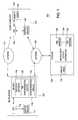
- FIG. 1is a system 100 for providing time synchronization in order to recreate an accurate storage state according to one or more embodiments of the present invention.
- the system 100comprises a media server 102 , a client computer 104 , a storage 106 , where each is coupled to each other through a network 108 .
- the system 100may include a data protection system for a computer environment that includes the client computer 104 .
- the media server 102is coupled to the client computer 104 and the computing environment through a network 110 (e.g. a Local Area Network).
- a network 110e.g. a Local Area Network
- the media server 102is a computing device (e.g., a laptop, a desktop, a Personal Desk Assistant (PDA), a tablet, a mobile phone and the like) that comprises a central processing unit (CPU) 112 , various support circuits 114 and a memory 116 .
- the CPU 112may comprise one or more commercially available microprocessors or microcontrollers that facilitate data processing and storage.
- Various support circuits 114facilitate operation of the CPU 112 and may include clock circuits, buses, power supplies, input/output circuits and/or the like.
- the memory 116includes a read only memory, random access memory, disk drive storage, optical storage, removable storage, and the like.
- the memory 116includes various data, such as a time synchronization history 120 .
- the memory 116includes various software packages, such as recovery software 118 and a synchronization module 122 .
- the recovery software 118includes software code for providing a point-in-time image to the client computer 104 as a
- the client computer 104is a computing device (e.g., a laptop, a desktop, a Personal Desk Assistant (PDA), a tablet, a mobile phone and the like) that comprises a central processing unit (CPU) 124 , various support circuits 126 and a memory 128 .
- the CPU 124may comprise one or more commercially available microprocessors or microcontrollers that facilitate data processing and storage.
- Various support circuits 126facilitate operation of the CPU 124 and may include clock circuits, buses, power supplies, input/output circuits and/or the like.
- the memory 114includes a read only memory, random access memory, disk drive storage, optical storage, removable storage, and the like.
- the memory 128includes various software packages, such as an agent 130 .
- the storage 106may include a data storage system (e.g., one or more storage devices) that includes a backup image 132 and input/output activity information 134 .
- the backup image 132includes one or more image files for representing a volume at a particular point-in-time.
- the input/output activity information 134may be an I/O stream or journal of storage and/or file system operations for the volume after the particular point-in-time. Accordingly, the storage and/or file system operations may be applied to the backup image 132 in order to create a point-in-time image that corresponds with a later point-in-time.
- the input/output activity informationcomprises time marker 136 for storing a local time at the client computer 104 as explained further below.
- the network 108comprises a communication system that connects computers by wire, cable, fiber optic, and/or wireless links facilitated by various types of well-known network elements, such as hubs, switches, routers, and the like.
- the network 108may employ various well-known protocols to communicate information amongst the network resources.
- the network 108may be part of the Internet or intranet using various communications infrastructure such as Ethernet, WiFi, WiMax, Fibre Channel, General Packet Radio Service (GPRS), and the like.
- the network 108forms a storage area network (SAN) that includes the media server 102 and the storage 106 .
- the network 108may be used to communicate storage traffic between the client computer 104 and the media server 102 .
- the network 110may be a local area network (LAN) for a computing environment that includes the client computer 104 .
- LANlocal area network
- the media server 102 and the client computer 104cooperate to provide time synchronization within the system 100 in order to enable accurate storage state recreation.
- the agent 130inserts the time markers 136 into the input/output activity information 134 (e.g., an I/O journal or stream that comprises one or more storage and/or file system operations) on a periodic basis (e.g., every fifteen minutes).
- the time markers 136may have known positions that are relative to the one or more storage and/or file system operations in the I/O stream.
- the time markers 136may be inserted into the I/O stream such that each time marker is positioned before and/or after an occurrence of a storage and/or file system operation.
- the input/output activity information 134is transmitted to the media server 102 for processing before storage in the storage 106 . Since the input/output activity information 134 (e.g., I/O stream) may be transmitted in-band (i.e., over the same transport), positions of the time markers 136 are maintained. At the media server 102 , the input/output activity information 134 is modified to include a server timestamp for each local client timestamp. Subsequently, a time skew between the media server 102 and the client computer 104 is determined. In one embodiment, the time skew is a difference in time between a recordation of a time marker at the client computer 104 and a reception of the time marker at the media server 102 . As explained below, the time skew may be stored in the time synchronization history 120 .
- the time skewmay be stored in the time synchronization history 120 .
- the synchronization module 122processes each segment (e.g., each storage and/or file system operation) of the input/output information 134 to identify the time markers 136 . Upon identification of a time marker of the time markers 136 , the synchronization module generates a server timestamp in order to update the time marker of the time markers 136 . In one embodiment, the synchronization module 122 stores the server timestamp with the local client timestamp associated with the client computer 104 . For example, the media server 102 executes a function that returns the system time (e.g., SystemTime( ). It is appreciated that the embodiments of the present invention may include operating systems with different methods for obtaining system timestamps. In another embodiment, the synchronization module 122 computes the time skew between the media server 102 and the client computer 104 and stores the time skew in the time marker of the time markers 136 and/or the time synchronization history 120 .
- each segmente.g., each storage and/or file system operation
- the client computer 104desires to recover lost, corrupted or deleted data at a particular point-in-time from the backup image 132 and the input/output information 134 .
- the client computer 104communicates a point-in-time image request to the recovery software 118 , which accesses the backup image 132 and uses the synchronization module 122 to determine an accurate time skew.
- the recovery module 118adjusts the particular point-in-time by the accurate time skew in order to be consistent with a server time at the media server 102 .
- the recovery module 118provides a point-in-time consistent image to the client computer 104 as a source for data recovery.
- the synchronization module 122identifies a particular time marker of the time markers 136 that is temporally closest to the particular point-in-time and/or is associated with the client computer 104 .
- the server timestamp at the particular time marker of the time markers 136is used to determine the accurate time skew.
- the local client timestamp associated with the client computer 104maps to the local client timestamp associated with the media server 102 .
- one or more storage and/or file system operations within the input/output activity information 134are actually associated with a point-in-time that is an adjustment of the particular point-in-time by the accurate time skew to account for a time difference between the media server 102 and the client computer 104 .
- the client computer 104may request a point-in-time image with image time of “05/14/2008 3:10:00.000000 pm”.
- the media server 102may use the synchronization module 122 to identify a time skew that existed at the image time of “5/14/2008 3:10:00.000000 pm” by referencing a time marker created by the client computer at 3:00 pm on May 14, 2008.
- the media server 102may accurately map the image time of “5/14/2008 3:10:00:000000 pm” on the client computer to a local server time at that precise instant.
- the time markermay indicate the accurate time skew to be 0.5 seconds.
- the image time of “5/14/2008 3:10:00:000000 pm”maps to an image time of “5/14/2008 3:10:00:500000 pm” at the media server 102 .
- the synchronization module 122may examine the time synchronization history to determine the accurate time skew for the client computer 104 . In another embodiment, the synchronization module 122 correlates various portions of the time synchronization history 120 . Generally, the time synchronization history 120 indicates one or more computed time skews for a plurality of client computers. Accordingly, a particular client computer may be associated with an average time skew, which may be used as the accurate time skew for a point-in-time image request. In another embodiment, the synchronization module 122 determines the accurate time skew for the particular client computer using a statistical analysis (e.g., a regression analysis). For example, one or more outlier time skew computations may significantly affect the accurate time skew. As such, the synchronization module 122 determines the accurate time skew that take the one or more outlier time skews into account.
- a statistical analysise.g., a regression analysis
- the media server 102may differentiate between time markers created by different client computers.
- the different client computerscan specify a point-in-time relative to a time marker. For example, instead of specifying an image time of “5/14/2008 19:20:00:000000”, the client computer 104 may specify the same my_marker — 5/14/2008@19:00:00+00:20:00.000000 as an adjusted point-in-time for data recovery. Because the media server 102 permits the plurality of client computers to specify time markers is that one client computer may now use one or more time markers created by another client computer. In an embodiment where one client computer has failed (e.g., a failover scenario), another client computer can recreate an accurate storage state from the point of view of the failed client computer.
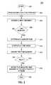
- FIG. 2is a method 200 for providing time synchronization within a data protection system in order to recreate an accurate storage state according to one or more embodiments of the present invention.
- the method 200starts at step 202 and proceeds to step 204 where the input/output stream is processed.
- the input/output streamcomprises a plurality of segments (e.g., one or more storage and/or file system operations and one or more time markers).
- a next segment of the input/output streamis accessed.
- a server timeis determined. In one embodiment, the function “SystemTime( )” provides the server time. In another embodiment, a system clock may be directly accessed in order to obtain the server time.
- a time skewis computed. In one embodiment, the time skew is a time difference between the server time and a local client timestamp of a client computer that is extracted from the time marker.
- the time markeris updated with the server time and stored in the input/output stream.
- a determinationis made as to whether there is a next segment in the input/output stream. If there is a next segment, the method 200 returns to step 206 where the next segment is accessed. If there is no next segment, the method 200 proceeds to step 218 .
- the updated input/output streamis stored (e.g., in storage 106 of FIG. 1 ).
- the method 200ends.
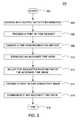
- FIG. 3is a method 300 for establishing an accurate time skew to provide a point-in-time consistent image according to one or more embodiments of the present invention.
- the method 300starts at step 302 and proceeds to step 304 where input/output activity information accessed.
- a point-in-time image request from a client computeris processed.
- a time synchronization historyis examined.
- an accurate time skewis established.
- the requested point-in-timeis adjusted by the accurate time skew.
- a point-in-time consistent imageis provided to the client computer.
- the accurate time skewis communicated to the client computer.
- the method 300ends.
Landscapes
- Engineering & Computer Science (AREA)
- Computer Security & Cryptography (AREA)
- Theoretical Computer Science (AREA)
- General Engineering & Computer Science (AREA)
- General Physics & Mathematics (AREA)
- Physics & Mathematics (AREA)
- Computer Networks & Wireless Communication (AREA)
- Signal Processing (AREA)
- Quality & Reliability (AREA)
- Health & Medical Sciences (AREA)
- Bioethics (AREA)
- General Health & Medical Sciences (AREA)
- Computer Hardware Design (AREA)
- Software Systems (AREA)
- Debugging And Monitoring (AREA)
Abstract
Description
Claims (18)
Priority Applications (1)
| Application Number | Priority Date | Filing Date | Title |
|---|---|---|---|
| US12/235,295US8327028B1 (en) | 2008-09-22 | 2008-09-22 | Method and apparatus for providing time synchronization in a data protection system |
Applications Claiming Priority (1)
| Application Number | Priority Date | Filing Date | Title |
|---|---|---|---|
| US12/235,295US8327028B1 (en) | 2008-09-22 | 2008-09-22 | Method and apparatus for providing time synchronization in a data protection system |
Publications (1)
| Publication Number | Publication Date |
|---|---|
| US8327028B1true US8327028B1 (en) | 2012-12-04 |
Family
ID=47226835
Family Applications (1)
| Application Number | Title | Priority Date | Filing Date |
|---|---|---|---|
| US12/235,295Active2030-05-04US8327028B1 (en) | 2008-09-22 | 2008-09-22 | Method and apparatus for providing time synchronization in a data protection system |
Country Status (1)
| Country | Link |
|---|---|
| US (1) | US8327028B1 (en) |
Cited By (6)
| Publication number | Priority date | Publication date | Assignee | Title |
|---|---|---|---|---|
| US20130054677A1 (en)* | 2011-08-30 | 2013-02-28 | Qatar Foundation | System and Method for Latency Monitoring |
| US20130054787A1 (en)* | 2011-08-30 | 2013-02-28 | Qatar Foundation | System and Method for Latency Monitoring |
| US20140372554A1 (en)* | 2013-06-14 | 2014-12-18 | Disney Enterprises, Inc. | Efficient synchronization of behavior trees using network significant nodes |
| US10261867B1 (en)* | 2016-01-25 | 2019-04-16 | Veritas Technologies Llc | Intelligent point-in-time selector |
| US11159591B2 (en)* | 2015-02-09 | 2021-10-26 | Ringcentral, Inc. | Method for transmitting data in a multimedia system, and software product and device for controlling the transmission of data in a multimedia system |
| US20220121620A1 (en)* | 2020-10-15 | 2022-04-21 | EMC IP Holding Company LLC | Hardening system clock for retention lock compliance enabled systems |
Citations (16)
| Publication number | Priority date | Publication date | Assignee | Title |
|---|---|---|---|---|
| US20020039370A1 (en)* | 2000-04-20 | 2002-04-04 | Mark Elliot | Precise network time transfer |
| US20040010487A1 (en)* | 2001-09-28 | 2004-01-15 | Anand Prahlad | System and method for generating and managing quick recovery volumes |
| US6731600B1 (en)* | 1999-02-08 | 2004-05-04 | Realnetworks, Inc. | System and method for determining network conditions |
| US20050240813A1 (en)* | 2004-04-08 | 2005-10-27 | Wataru Okada | Restore method for backup |
| US20060282510A1 (en)* | 2005-06-13 | 2006-12-14 | Lee Preimesberger | Multicast data distribution |
| US20070198706A1 (en)* | 2006-02-09 | 2007-08-23 | Marco Mechelli | Method, system and computer program for collecting information with improved time-stamp accuracy |
| US20070255823A1 (en)* | 2006-05-01 | 2007-11-01 | International Business Machines Corporation | Method for low-overhead message tracking in a distributed messaging system |
| US20070260717A1 (en)* | 2006-04-18 | 2007-11-08 | Yoshiki Kano | Method and apparatus of WAFS backup managed in centralized center |
| US20070268938A1 (en)* | 2006-05-19 | 2007-11-22 | Dowd Gregory Louis | Network time protocol precision timestamping service |
| US20070282921A1 (en)* | 2006-05-22 | 2007-12-06 | Inmage Systems, Inc. | Recovery point data view shift through a direction-agnostic roll algorithm |
| US20080049743A1 (en)* | 2006-02-01 | 2008-02-28 | Zampetti George P | Enhanced clock control in packet networks |
| US20090041053A1 (en)* | 2007-08-06 | 2009-02-12 | Shishir Birmiwal | Time-offset regulated method and system for synchronization and rate control of media data |
| US20090157469A1 (en)* | 2007-12-12 | 2009-06-18 | D Urso Jeffrey M | System and Method for Management of Multi-Session, Sequential, Synchronized Electronic Conferencing |
| US20090282203A1 (en)* | 2008-05-09 | 2009-11-12 | Nils Haustein | Managing storage and migration of backup data |
| US20090327445A1 (en)* | 2008-06-30 | 2009-12-31 | Van Rietschote Hans F | Continuous data protection and remote block-level storage for a data volume |
| US20100034103A1 (en)* | 2008-08-06 | 2010-02-11 | International Business Machines Corporation | Robust Jitter-Free Remote Clock Offset Measuring Method |
- 2008
- 2008-09-22USUS12/235,295patent/US8327028B1/enactiveActive
Patent Citations (16)
| Publication number | Priority date | Publication date | Assignee | Title |
|---|---|---|---|---|
| US6731600B1 (en)* | 1999-02-08 | 2004-05-04 | Realnetworks, Inc. | System and method for determining network conditions |
| US20020039370A1 (en)* | 2000-04-20 | 2002-04-04 | Mark Elliot | Precise network time transfer |
| US20040010487A1 (en)* | 2001-09-28 | 2004-01-15 | Anand Prahlad | System and method for generating and managing quick recovery volumes |
| US20050240813A1 (en)* | 2004-04-08 | 2005-10-27 | Wataru Okada | Restore method for backup |
| US20060282510A1 (en)* | 2005-06-13 | 2006-12-14 | Lee Preimesberger | Multicast data distribution |
| US20080049743A1 (en)* | 2006-02-01 | 2008-02-28 | Zampetti George P | Enhanced clock control in packet networks |
| US20070198706A1 (en)* | 2006-02-09 | 2007-08-23 | Marco Mechelli | Method, system and computer program for collecting information with improved time-stamp accuracy |
| US20070260717A1 (en)* | 2006-04-18 | 2007-11-08 | Yoshiki Kano | Method and apparatus of WAFS backup managed in centralized center |
| US20070255823A1 (en)* | 2006-05-01 | 2007-11-01 | International Business Machines Corporation | Method for low-overhead message tracking in a distributed messaging system |
| US20070268938A1 (en)* | 2006-05-19 | 2007-11-22 | Dowd Gregory Louis | Network time protocol precision timestamping service |
| US20070282921A1 (en)* | 2006-05-22 | 2007-12-06 | Inmage Systems, Inc. | Recovery point data view shift through a direction-agnostic roll algorithm |
| US20090041053A1 (en)* | 2007-08-06 | 2009-02-12 | Shishir Birmiwal | Time-offset regulated method and system for synchronization and rate control of media data |
| US20090157469A1 (en)* | 2007-12-12 | 2009-06-18 | D Urso Jeffrey M | System and Method for Management of Multi-Session, Sequential, Synchronized Electronic Conferencing |
| US20090282203A1 (en)* | 2008-05-09 | 2009-11-12 | Nils Haustein | Managing storage and migration of backup data |
| US20090327445A1 (en)* | 2008-06-30 | 2009-12-31 | Van Rietschote Hans F | Continuous data protection and remote block-level storage for a data volume |
| US20100034103A1 (en)* | 2008-08-06 | 2010-02-11 | International Business Machines Corporation | Robust Jitter-Free Remote Clock Offset Measuring Method |
Cited By (9)
| Publication number | Priority date | Publication date | Assignee | Title |
|---|---|---|---|---|
| US20130054677A1 (en)* | 2011-08-30 | 2013-02-28 | Qatar Foundation | System and Method for Latency Monitoring |
| US20130054787A1 (en)* | 2011-08-30 | 2013-02-28 | Qatar Foundation | System and Method for Latency Monitoring |
| US9130842B2 (en)* | 2011-08-30 | 2015-09-08 | Qatar Foundation | System and method for latency monitoring |
| US20140372554A1 (en)* | 2013-06-14 | 2014-12-18 | Disney Enterprises, Inc. | Efficient synchronization of behavior trees using network significant nodes |
| US9560131B2 (en)* | 2013-06-14 | 2017-01-31 | Disney Enterprises, Inc. | Efficient synchronization of behavior trees using network significant nodes |
| US11159591B2 (en)* | 2015-02-09 | 2021-10-26 | Ringcentral, Inc. | Method for transmitting data in a multimedia system, and software product and device for controlling the transmission of data in a multimedia system |
| US10261867B1 (en)* | 2016-01-25 | 2019-04-16 | Veritas Technologies Llc | Intelligent point-in-time selector |
| US20220121620A1 (en)* | 2020-10-15 | 2022-04-21 | EMC IP Holding Company LLC | Hardening system clock for retention lock compliance enabled systems |
| US11762806B2 (en)* | 2020-10-15 | 2023-09-19 | EMC IP Holding Company LLC | Hardening system clock for retention lock compliance enabled systems |
Similar Documents
| Publication | Publication Date | Title |
|---|---|---|
| US9875042B1 (en) | Asynchronous replication | |
| US9557925B1 (en) | Thin replication | |
| US8327028B1 (en) | Method and apparatus for providing time synchronization in a data protection system | |
| US8060714B1 (en) | Initializing volumes in a replication system | |
| EP2378718B1 (en) | Method, node and system for controlling version in distributed system | |
| US10565071B2 (en) | Smart data replication recoverer | |
| US8839031B2 (en) | Data consistency between virtual machines | |
| US10944818B1 (en) | Time synchronization monitoring with client mirroring | |
| US20130238552A1 (en) | Systems and methods for synchronizing files in a networked communication system | |
| US20130166505A1 (en) | Monitoring replication lag between geographically dispersed sites | |
| US10069942B2 (en) | Method and apparatus for changing configurations | |
| US20110099148A1 (en) | Verification Of Remote Copies Of Data | |
| US8127174B1 (en) | Method and apparatus for performing transparent in-memory checkpointing | |
| CN105468475A (en) | Backup method and backup device of database | |
| CN110196680B (en) | Data processing method, device and storage medium | |
| US20110137874A1 (en) | Methods to Minimize Communication in a Cluster Database System | |
| CN1965526B (en) | Adjustable self-running safety clock | |
| WO2017014814A1 (en) | Replicating memory volumes | |
| US10374810B2 (en) | Middleware system validation tool | |
| US9946617B2 (en) | Optimized recovery in data replication environments | |
| US10671596B1 (en) | Consistency determination | |
| US8180729B2 (en) | Data replication method | |
| Pasupuleti | Achieving High Write Availability in Distributed Systems through Multi-Leader Replication | |
| CN106951443A (en) | The method, apparatus and system of copies synchronized based on distributed system | |
| US12019467B2 (en) | Estimation of event generation times to synchronize recordation data |
Legal Events
| Date | Code | Title | Description |
|---|---|---|---|
| AS | Assignment | Owner name:SYMANTEC CORPORATION, CALIFORNIA Free format text:ASSIGNMENT OF ASSIGNORS INTEREST;ASSIGNORS:SHAH, DHARMESH;SHARMA, GOPAL;LOPEZ, GRIZEL;AND OTHERS;SIGNING DATES FROM 20080828 TO 20080922;REEL/FRAME:021567/0847 | |
| AS | Assignment | Owner name:SYMANTEC CORPORATION, CALIFORNIA Free format text:ADDRESS CHANGE OF ASSIGNEE;ASSIGNOR:SYMANTEC CORPORATION;REEL/FRAME:029219/0888 Effective date:20090905 | |
| STCF | Information on status: patent grant | Free format text:PATENTED CASE | |
| AS | Assignment | Owner name:VERITAS US IP HOLDINGS LLC, CALIFORNIA Free format text:ASSIGNMENT OF ASSIGNORS INTEREST;ASSIGNOR:SYMANTEC CORPORATION;REEL/FRAME:037697/0412 Effective date:20160129 | |
| AS | Assignment | Owner name:WILMINGTON TRUST, NATIONAL ASSOCIATION, AS COLLATERAL AGENT, CONNECTICUT Free format text:SECURITY INTEREST;ASSIGNOR:VERITAS US IP HOLDINGS LLC;REEL/FRAME:037891/0726 Effective date:20160129 Owner name:BANK OF AMERICA, N.A., AS COLLATERAL AGENT, NORTH CAROLINA Free format text:SECURITY INTEREST;ASSIGNOR:VERITAS US IP HOLDINGS LLC;REEL/FRAME:037891/0001 Effective date:20160129 Owner name:BANK OF AMERICA, N.A., AS COLLATERAL AGENT, NORTH Free format text:SECURITY INTEREST;ASSIGNOR:VERITAS US IP HOLDINGS LLC;REEL/FRAME:037891/0001 Effective date:20160129 Owner name:WILMINGTON TRUST, NATIONAL ASSOCIATION, AS COLLATE Free format text:SECURITY INTEREST;ASSIGNOR:VERITAS US IP HOLDINGS LLC;REEL/FRAME:037891/0726 Effective date:20160129 | |
| AS | Assignment | Owner name:VERITAS TECHNOLOGIES LLC, CALIFORNIA Free format text:MERGER AND CHANGE OF NAME;ASSIGNORS:VERITAS US IP HOLDINGS LLC;VERITAS TECHNOLOGIES LLC;REEL/FRAME:038455/0752 Effective date:20160329 | |
| FPAY | Fee payment | Year of fee payment:4 | |
| MAFP | Maintenance fee payment | Free format text:PAYMENT OF MAINTENANCE FEE, 8TH YEAR, LARGE ENTITY (ORIGINAL EVENT CODE: M1552); ENTITY STATUS OF PATENT OWNER: LARGE ENTITY Year of fee payment:8 | |
| AS | Assignment | Owner name:WILMINGTON TRUST, NATIONAL ASSOCIATION, AS NOTES COLLATERAL AGENT, DELAWARE Free format text:SECURITY INTEREST;ASSIGNOR:VERITAS TECHNOLOGIES LLC;REEL/FRAME:054370/0134 Effective date:20200820 | |
| AS | Assignment | Owner name:VERITAS US IP HOLDINGS, LLC, CALIFORNIA Free format text:TERMINATION AND RELEASE OF SECURITY IN PATENTS AT R/F 037891/0726;ASSIGNOR:WILMINGTON TRUST, NATIONAL ASSOCIATION, AS COLLATERAL AGENT;REEL/FRAME:054535/0814 Effective date:20201127 | |
| MAFP | Maintenance fee payment | Free format text:PAYMENT OF MAINTENANCE FEE, 12TH YEAR, LARGE ENTITY (ORIGINAL EVENT CODE: M1553); ENTITY STATUS OF PATENT OWNER: LARGE ENTITY Year of fee payment:12 | |
| AS | Assignment | Owner name:ACQUIOM AGENCY SERVICES LLC, AS ASSIGNEE, COLORADO Free format text:ASSIGNMENT OF SECURITY INTEREST IN PATENT COLLATERAL;ASSIGNOR:BANK OF AMERICA, N.A., AS ASSIGNOR;REEL/FRAME:069440/0084 Effective date:20241122 | |
| AS | Assignment | Owner name:JPMORGAN CHASE BANK. N.A., NEW YORK Free format text:SECURITY INTEREST;ASSIGNORS:VERITAS TECHNOLOGIES LLC;COHESITY, INC.;REEL/FRAME:069890/0001 Effective date:20241209 | |
| AS | Assignment | Owner name:VERITAS TECHNOLOGIES LLC, CALIFORNIA Free format text:RELEASE BY SECURED PARTY;ASSIGNOR:WILMINGTON TRUST, NATIONAL ASSOCIATION, AS NOTES COLLATERAL AGENT;REEL/FRAME:069634/0584 Effective date:20241209 | |
| AS | Assignment | Owner name:VERITAS TECHNOLOGIES LLC (F/K/A VERITAS US IP HOLDINGS LLC), CALIFORNIA Free format text:RELEASE BY SECURED PARTY;ASSIGNOR:ACQUIOM AGENCY SERVICES LLC, AS COLLATERAL AGENT;REEL/FRAME:069712/0090 Effective date:20241209 | |
| AS | Assignment | Owner name:COHESITY, INC., CALIFORNIA Free format text:ASSIGNMENT OF ASSIGNORS INTEREST;ASSIGNOR:VERITAS TECHNOLOGIES LLC;REEL/FRAME:070335/0013 Effective date:20250213 | |
| AS | Assignment | Owner name:JPMORGAN CHASE BANK, N.A., NEW YORK Free format text:AMENDMENT NO. 1 TO PATENT SECURITY AGREEMENT;ASSIGNORS:VERITAS TECHNOLOGIES LLC;COHESITY, INC.;REEL/FRAME:070779/0001 Effective date:20250408 |