US8326425B2 - Feedthrough connector for implantable device - Google Patents
Feedthrough connector for implantable deviceDownload PDFInfo
- Publication number
- US8326425B2 US8326425B2US11/278,047US27804706AUS8326425B2US 8326425 B2US8326425 B2US 8326425B2US 27804706 AUS27804706 AUS 27804706AUS 8326425 B2US8326425 B2US 8326425B2
- Authority
- US
- United States
- Prior art keywords
- feedthrough
- implantable device
- upper contact
- contact surface
- housing
- Prior art date
- Legal status (The legal status is an assumption and is not a legal conclusion. Google has not performed a legal analysis and makes no representation as to the accuracy of the status listed.)
- Expired - Fee Related, expires
Links
Images


Classifications
- A—HUMAN NECESSITIES
- A61—MEDICAL OR VETERINARY SCIENCE; HYGIENE
- A61N—ELECTROTHERAPY; MAGNETOTHERAPY; RADIATION THERAPY; ULTRASOUND THERAPY
- A61N1/00—Electrotherapy; Circuits therefor
- A61N1/18—Applying electric currents by contact electrodes
- A61N1/32—Applying electric currents by contact electrodes alternating or intermittent currents
- A61N1/36—Applying electric currents by contact electrodes alternating or intermittent currents for stimulation
- A61N1/372—Arrangements in connection with the implantation of stimulators
- A61N1/375—Constructional arrangements, e.g. casings
- A61N1/3752—Details of casing-lead connections
- A61N1/3754—Feedthroughs
Definitions
- This inventionrelates to the field of implantable devices and more specifically to a feedthrough connector for an implantable device.
- Implantable medical devicesare used to treat many conditions.
- Implantable devicessuch as pacemakers and defibrillators include electronics mounted within a housing which are typically operatively connected to a lead which is implanted on or in the heart.
- the leads implanted in or about the heartcan be used to reverse certain life threatening arrhythmia, or to stimulate contraction of the heart. Electrical energy is applied to the heart via electrodes on the leads to return the heart to normal rhythm.
- An implantable devicecan include a pulse generator which includes a device housing electrically and mechanically connected to a header.
- the headeris used to couple a conductor of a lead with the electronics of the implantable device.
- a connector assembly in the headeris used to couple a cardiac stimulator system such as a pacemaker, an anti-tachycardia device, a cardiac heart failure device, a cardioverter or a defibrillator with a lead having an electrode for making contact with a portion of the heart.
- the headeris electrically connected to the device housing by interconnects leading from the header to electrical feedthroughs which pass through the housing to connect to electronic components in the housing.
- an implantable devicein one example, includes a header, a housing, one or more electrical connectors connected to the header, and a feedthrough assembly mounted to the housing.
- the feedthrough assemblyincludes a nonconductive base having one or more holes therethrough.
- the feedthrough assemblyfurther includes one or more feedthrough pins, each feedthrough pin extending through one of the one or more holes, each feedthrough pin including a pin body and an upper contact surface for connecting to one or more of the electrical connectors.
- the upper contact surfaceincludes a larger surface area than a cross-sectional area of the pin body.
- FIG. 1shows a view of an implantable system according to at least one embodiment.
- FIG. 2shows an exploded view of the implantable device of FIG. 1 .
- FIG. 3shows a close up view of a connection between a header and a pulse generator housing, in accordance with one embodiment.
- FIG. 4shows a perspective view of a feedthrough assembly, in accordance with one embodiment.
- FIG. 5shows a side view of the feedthrough assembly of FIG. 4 .
- FIG. 6shows a side view of a feedthrough pin, in accordance with one embodiment.
- FIG. 7shows a cross-section side view of a feedthrough pin, in accordance with one embodiment.
- FIG. 1shows an implantable medical device 100 , in accordance with one embodiment.
- Device 100includes a pulse generator 105 and at least one lead 110 .
- the pulse generator 105is generally implanted into a subcutaneous pocket made in the wall of the chest. Alternatively, the pulse generator 105 is placed in a subcutaneous or submuscular pocket made in the abdomen, or in other locations.
- Pulse generator 105generally includes a hermetically sealed housing 103 and a header 104 . Header 104 is mechanically and electrically coupled to housing 103 .
- Pulse generator 105can include a power supply such as a battery, a capacitor, and other components housed in housing 103 .
- the pulse generator 105can also include microprocessors to provide processing, evaluation, and to determine and deliver electrical shocks and pulses of different energy levels and timing for defibrillation, cardioversion, and pacing to a heart in response to cardiac arrhythmia including fibrillation, tachycardia, heart failure, and bradycardia.
- Lead 110includes a lead body 113 having a proximal end 112 , where the lead is coupled at header 104 of pulse generator 105 .
- the lead 110extends to a distal end 114 , which is coupled with a portion of a heart, when implanted.
- the distal end 114 of the lead 110includes one or more electrodes 120 , 121 which electrically couple the lead 110 with a heart.
- electrodescan be located medially or at other locations along the lead.
- At least one electrical conductoris disposed within the lead 110 and extends from the proximal end 112 to the electrode(s) 120 , 121 . The electrical conductors carry electrical current and pulses between the pulse generator 105 and the electrode(s) 120 , 121 .
- device 100is suitable for use with implantable electrical stimulators, such as, but not limited to, pulse generators, neuro-stimulators, skeletal stimulators, central nervous system stimulators, or stimulators for the treatment of pain.
- implantable electrical stimulatorssuch as, but not limited to, pulse generators, neuro-stimulators, skeletal stimulators, central nervous system stimulators, or stimulators for the treatment of pain.
- the systemcan also be utilized as a sensor or a receiver.
- the electrodescan be used, for sensing, pacing, and/or shocking, for example.
- FIG. 2illustrates a side exploded view of pulse generator housing 103 and header 104 .
- FIG. 3shows a close up view of a connection between header 104 and a pulse generator housing 103 , in accordance with one embodiment.
- Header 104includes one or more longitudinal bores 140 that are configured to receive a lead terminal of lead 110 ( FIG. 1 ).
- the lead terminalcan include one or more contacts to contact corresponding contacts 220 , 221 within header 104 .
- header 104generally includes a header body 210 having the longitudinal bore 140 formed therein and the one or more electrical contacts 220 , 221 located within the bore 140 to contact corresponding contacts of lead 110 .
- Contacts 220 , 221are electrically connected to the electronics in pulse generator housing 103 via a grouping 230 of connectors 235 .
- each individual connector 235is electrically coupled to one or more of contacts 220 , 221 .
- Each connector 235is also connected to a feedthrough pin 245 of a feedthrough assembly 240 mounted to pulse generator housing 103 .
- feedthrough pins 245are electrically connected to electronic components with housing 103 .
- feedthrough pins 245are oriented so as to define a connection surface generally parallel to a major surface 255 of the housing 103 .
- feedthrough pins 245are oriented so that each pin's longitudinal axis is perpendicular to surface 255 .
- FIG. 4shows a perspective view of feedthrough assembly 240
- FIG. 5shows a side view of the feedthrough assembly
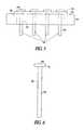
- FIG. 6shows a side view of feedthrough pin 245 , in accordance with one embodiment.
- Feedthrough assembly 240includes a conductive portion 410 , a nonconductive support base 420 and one or more feedthrough pins 245 .
- Conductive portion 410supports and is located around the periphery of nonconductive base 420 .
- conductive portion 410includes titanium and is laser welded to housing 103 .
- Conductive portion 410can further include a ledge 520 which supports part of nonconductive base 420 .
- base 420can be attached to conductive portion 410 by a gold braze joint.
- Non-conductive base 420can include a ceramic, for example.
- Nonconductive base 420includes one or more holes 510 therethrough. Holes 510 extend through the base 420 and are sized to receive feedthrough pins 245 . In one example, feedthrough pins 245 are attached at holes 510 by brazing.
- Feedthrough assembly 240further includes the one or more feedthrough pins 245 , with each feedthrough pin 245 extending through one of the plurality of holes 510 .
- Each feedthrough pin 245is a conductive material, such as Pt—Ir, and includes a shaft or other pin body 430 and a head 431 having an upper contact surface 440 for connecting to one or more of the electrical connectors 235 ( FIG. 3 ).
- Upper contact surface 440 of each pin 245has a larger surface area than a cross-sectional area of the pin body 430 .
- feedthrough pins 245define a nailhead shape. As will be discussed, this provides more surface area for making the connection between connector 235 and feedthrough pin 245 .
- a lower surface of head 431is seated against the non-conductive base 420 .
- electrical connectors 235extend from the header 104 and are positioned in a predetermined configuration such that the connectors retain their position as the header sub-assembly is mounted to the housing 103 .
- the connectors 235can be wire ribbons that hold their shape as a group as originally configured.
- the sub-assembly of the header 104can be assembled and then positioned on top of the housing 103 .
- the feedthrough pins 245are positioned in a configuration to substantially match the configuration of the one or more electrical connectors 235 , such that the final location of the connectors 235 is such that they rest somewhere on or above the upper surface of feedthrough pins 245 .
- each separate connector 235does not need to be individually routed from the header to a feedthrough pin.
- each connector 235is in the proper position as placed.
- the feedthrough pins 245have expanded nailhead connection surfaces 440 , there can be increased variation allowable between the locations of the connectors 235 relative to the feedthrough pins 245 and the connection can still be made successfully.
- electrical connectors 235include wire ribbons that are pre-formed in a curved or bent configuration so that at least a portion of each connector 235 is located on or above the upper contact surface 440 of feedthrough pin 245 when the header 104 is placed onto the housing 103 .
- electrical connectors 235can include round wire connectors or combinations of round wires and/or ribbon connectors. The connectors 235 can be attached to the feedthrough pins 245 by welding, brazing, conductive epoxy or other techniques.
- header 104 sub-assemblyis formed such that connectors 235 extend from the header 104 in a predetermined configuration.
- the header 104is positioned over the housing 103 so that the connectors 235 are above or contact the upper surfaces 440 of feedthrough pins 245 . If the connectors 235 are above the surface 440 , then they are pressed down before connecting.
- the connectors 235are then electrically and mechanically attached to the feedthrough pins 245 by welding, soldering, brazing, or conductive epoxy, for example. As noted, this eliminates the need for manually routing each individual connector from the header to the feedthrough to perform a connection.
- the flat head connection surface 440saves expensive material since the feedthrough pin 245 can be relatively shorter than a feedthrough that extends above the surface for attaching to a connector from a header. Also, this lower profile also allows for a slimmer housing 104 and overall pulse generator device 100 . Also, as noted, the flat head broad surface connection 440 allows more variance in the precise location of connectors 235 from the header, which lowers manufacturing complexity.
- FIG. 7shows a cross-section side view of a feedthrough pin 500 , in accordance with one embodiment.
- feedthrough pin 500is a conductive material, such as Pt—Ir, and includes a shaft or other pin body 530 and a head 531 having an upper contact surface 540 for connecting to one or more electrical connectors 535 , which extend from a header, for example.
- Upper contact surface 540 of each pin 500has a larger surface area than a cross-sectional area of the pin body 530 .
- pin 500includes a protrusion 555 extending above surface 540 .
- Connector 535includes a corresponding hole 537 . When assembling the connector 535 to the feedthrough pin 500 , the user can press the connector 535 over the protrusion 555 so that the protrusion extends through hole 537 . This helps align the connector relative to the feedthrough pin.
- the header discussed hereincan include an antennae and/or electronic components that are used to electrically communicate outside the device.
Landscapes
- Health & Medical Sciences (AREA)
- Engineering & Computer Science (AREA)
- Biomedical Technology (AREA)
- Nuclear Medicine, Radiotherapy & Molecular Imaging (AREA)
- Radiology & Medical Imaging (AREA)
- Life Sciences & Earth Sciences (AREA)
- Animal Behavior & Ethology (AREA)
- General Health & Medical Sciences (AREA)
- Public Health (AREA)
- Veterinary Medicine (AREA)
- Electrotherapy Devices (AREA)
Abstract
Description
Claims (20)
Priority Applications (4)
| Application Number | Priority Date | Filing Date | Title |
|---|---|---|---|
| US11/278,047US8326425B2 (en) | 2006-03-30 | 2006-03-30 | Feedthrough connector for implantable device |
| EP07758308.6AEP1998851B1 (en) | 2006-03-30 | 2007-03-12 | Feedthrough connector for implantable device |
| JP2009503127AJP5179469B2 (en) | 2006-03-30 | 2007-03-12 | Implantable device and method of assembling an implantable device |
| PCT/US2007/063749WO2007117812A2 (en) | 2006-03-30 | 2007-03-12 | Feedthrough connector for implantable device |
Applications Claiming Priority (1)
| Application Number | Priority Date | Filing Date | Title |
|---|---|---|---|
| US11/278,047US8326425B2 (en) | 2006-03-30 | 2006-03-30 | Feedthrough connector for implantable device |
Publications (2)
| Publication Number | Publication Date |
|---|---|
| US20070239222A1 US20070239222A1 (en) | 2007-10-11 |
| US8326425B2true US8326425B2 (en) | 2012-12-04 |
Family
ID=38474133
Family Applications (1)
| Application Number | Title | Priority Date | Filing Date |
|---|---|---|---|
| US11/278,047Expired - Fee RelatedUS8326425B2 (en) | 2006-03-30 | 2006-03-30 | Feedthrough connector for implantable device |
Country Status (4)
| Country | Link |
|---|---|
| US (1) | US8326425B2 (en) |
| EP (1) | EP1998851B1 (en) |
| JP (1) | JP5179469B2 (en) |
| WO (1) | WO2007117812A2 (en) |
Cited By (10)
| Publication number | Priority date | Publication date | Assignee | Title |
|---|---|---|---|---|
| US20110232961A1 (en)* | 2010-03-29 | 2011-09-29 | Biotronik Se & Co. Kg | Electrical Feedthrough, in Particular for Medical Implants |
| US20110235239A1 (en)* | 2010-03-29 | 2011-09-29 | Biotronik Se & Co. Kg | Electrical Feedthrough of a Capacitor for Medical Implants and Method for the Production and Use Thereof |
| US20120193118A1 (en)* | 2011-01-31 | 2012-08-02 | Heraeus Precious Materials Gmbh & Co. Kg | Directly applicable electrical bushing |
| US20130183863A1 (en)* | 2012-01-12 | 2013-07-18 | Biotronik Se & Co. Kg | Electrical connecting element and combination comprising an elecrical connecting element and component |
| US20150250386A1 (en)* | 2012-09-28 | 2015-09-10 | Csem Centre Suisse D'electronique Et De Microtechnique Sa -Recherche Et Developpement | Implantable devices |
| US9306318B2 (en) | 2011-01-31 | 2016-04-05 | Heraeus Deutschland GmbH & Co. KG | Ceramic bushing with filter |
| US9509272B2 (en) | 2011-01-31 | 2016-11-29 | Heraeus Deutschland GmbH & Co. KG | Ceramic bushing with filter |
| US9504840B2 (en) | 2011-01-31 | 2016-11-29 | Heraeus Deutschland GmbH & Co. KG | Method of forming a cermet-containing bushing for an implantable medical device having a connecting layer |
| US9552899B2 (en) | 2011-01-31 | 2017-01-24 | Heraeus Deutschland GmbH & Co. KG | Ceramic bushing for an implantable medical device |
| US10092766B2 (en) | 2011-11-23 | 2018-10-09 | Heraeus Deutschland GmbH & Co. KG | Capacitor and method to manufacture the capacitor |
Families Citing this family (11)
| Publication number | Priority date | Publication date | Assignee | Title |
|---|---|---|---|---|
| US7803014B2 (en)* | 2006-03-30 | 2010-09-28 | Cardiac Pacemakers, Inc. | Implantable medical device assembly and manufacturing method |
| US8326425B2 (en) | 2006-03-30 | 2012-12-04 | Cardiac Pacemakers, Inc. | Feedthrough connector for implantable device |
| EP2214773A2 (en) | 2007-10-02 | 2010-08-11 | Medtronic, Inc. | Connector assemblies and contacts for implantable medical electrical systems |
| EP2217325A1 (en)* | 2007-10-03 | 2010-08-18 | Medtronic, Inc. | Connector assemblies for implantable medical electrical systems |
| US20090281586A1 (en)* | 2008-05-08 | 2009-11-12 | Pacesetter, Inc. | Implantable pulse generator emu filtered feedthru |
| US8718774B2 (en)* | 2009-04-23 | 2014-05-06 | Cardiac Pacemakers, Inc. | Housings for implantable medical devices and methods for forming housings |
| US9403022B2 (en) | 2010-01-29 | 2016-08-02 | Medtronic, Inc. | Header assembly for implantable medical device |
| WO2015031630A1 (en)* | 2013-08-28 | 2015-03-05 | Heartware, Inc. | Pass-through assembly |
| KR101656723B1 (en)* | 2015-06-30 | 2016-09-12 | 재단법인 오송첨단의료산업진흥재단 | Feedthrough making method |
| EP3332836B1 (en) | 2016-12-09 | 2019-07-03 | BIOTRONIK SE & Co. KG | Feedthrough of an implantable medical electronic device |
| EP3437693A1 (en)* | 2017-08-02 | 2019-02-06 | BIOTRONIK SE & Co. KG | Connection pin and performing and method for producing a connection pin |
Citations (44)
| Publication number | Priority date | Publication date | Assignee | Title |
|---|---|---|---|---|
| US4352951A (en)* | 1977-09-26 | 1982-10-05 | Medical Components Corp. | Ceramic seals between spaced members such as a terminal pin and a ferrule |
| US4399819A (en) | 1981-12-21 | 1983-08-23 | Telectronics Pty. Ltd. | Heart pacer mechanical construction |
| GB2127629A (en)* | 1982-09-03 | 1984-04-11 | Mirowski Mieczyslaw | Implantable medical device with sealed electrical coupling |
| EP0405838A2 (en) | 1989-06-30 | 1991-01-02 | E.I. Du Pont De Nemours And Company | Header device |
| US5235742A (en) | 1989-11-20 | 1993-08-17 | Siemens Pacesetter, Inc. | Method of making an implantable device |
| US5660177A (en) | 1991-11-04 | 1997-08-26 | Biofield Corp. | D.C. biopotential sensing electrode assemblies for apparatus for disease, injury and bodily condition screening or sensing |
| US5679026A (en)* | 1995-12-21 | 1997-10-21 | Ventritex, Inc. | Header adapter for an implantable cardiac stimulation device |
| US5755743A (en)* | 1996-06-05 | 1998-05-26 | Implex Gmbh Spezialhorgerate | Implantable unit |
| US5759197A (en)* | 1994-10-04 | 1998-06-02 | Medtronic, Inc. | Protective feedthrough |
| US5782891A (en) | 1994-06-16 | 1998-07-21 | Medtronic, Inc. | Implantable ceramic enclosure for pacing, neurological, and other medical applications in the human body |
| US5871515A (en)* | 1997-08-01 | 1999-02-16 | Medtronic, Inc. | Attachment apparatus and method for an implantable medical device employing ultrasonic energy |
| EP0916364A2 (en) | 1997-11-13 | 1999-05-19 | Maxwell Energy Products, Inc. | Hermetically sealed emi feedthrough filter capacitor for human implant and other applications |
| US5942842A (en)* | 1992-02-07 | 1999-08-24 | Fogle, Jr.; Homer William | Hermetically-sealed electrically-absorptive low-pass radio frequency filters and electromagnetically lossy ceramic materials for said filters |
| US5951595A (en)* | 1996-05-13 | 1999-09-14 | Pacesetteer, Inc. | Setscrewless connector assembly for implantable medical devices |
| US6026325A (en) | 1998-06-18 | 2000-02-15 | Pacesetter, Inc. | Implantable medical device having an improved packaging system and method for making electrical connections |
| US6044302A (en)* | 1999-01-07 | 2000-03-28 | Cardiac Pacemakers, Inc. | Apparatus for connecting a left ventricular access lead to a cardiac rhythm management device |
| US6052623A (en)* | 1998-11-30 | 2000-04-18 | Medtronic, Inc. | Feedthrough assembly for implantable medical devices and methods for providing same |
| US6205358B1 (en) | 1997-08-01 | 2001-03-20 | Medtronic, Inc. | Method of making ultrasonically welded, staked of swaged components in an implantable medical device |
| US20020027484A1 (en)* | 2000-09-07 | 2002-03-07 | Stevenson Robert A. | Feedthrough capacitor filter assemblies with leak detection vents |
| US6414835B1 (en)* | 2000-03-01 | 2002-07-02 | Medtronic, Inc. | Capacitive filtered feedthrough array for an implantable medical device |
| US6428368B1 (en)* | 2001-03-26 | 2002-08-06 | Pacesetter, Inc. | Side actuated lead connector assembly for implantable tissue stimulation device |
| US6456256B1 (en) | 2001-08-03 | 2002-09-24 | Cardiac Pacemakers, Inc. | Circumferential antenna for an implantable medical device |
| US6459935B1 (en)* | 2000-07-13 | 2002-10-01 | Avx Corporation | Integrated filter feed-thru |
| US6519133B1 (en)* | 1999-11-20 | 2003-02-11 | Biotronik Mess-Und Therapiegerate Gmbh & Co. | Filter feedthrough |
| US20030040780A1 (en)* | 1997-08-01 | 2003-02-27 | Medtronic, Inc. | Ultrasonically welded, staked or swaged components in an implantable medical device |
| US20030139096A1 (en)* | 2000-09-07 | 2003-07-24 | Stevenson Robert A. | EMI filterd connectors using internally grounded feedthrough capacitors |
| WO2003073450A1 (en) | 2002-02-28 | 2003-09-04 | Greatbatch-Sierra, Inc. | Emi feedthrough filter terminal assembly utilizing hermetic seal for electrical attachment between lead wires and capacitor |
| US6622046B2 (en) | 2001-05-07 | 2003-09-16 | Medtronic, Inc. | Subcutaneous sensing feedthrough/electrode assembly |
| US20040012462A1 (en)* | 2001-05-29 | 2004-01-22 | Sung-Youl Kim | Feed-through filter having improved shielding and mounting functions |
| US20040078062A1 (en)* | 2002-10-18 | 2004-04-22 | Cardiac Pacemakers, Inc. | Header for implantable medical device |
| US20040116976A1 (en)* | 2002-12-16 | 2004-06-17 | Cardiac Pacemakers, Inc. | Interconnect for implantable medical device header |
| US20040215280A1 (en)* | 2003-04-23 | 2004-10-28 | Dublin Garry L. | Telemetry antenna for an implantable medical device |
| US20040215281A1 (en)* | 2000-11-03 | 2004-10-28 | Cardiac Pacemakers, Inc. | Capacitor having a feedthrough assembly with a coupling member |
| US6817905B2 (en) | 2000-06-20 | 2004-11-16 | Medtronic, Inc. | Connector assembly for an implantable medical device and process for making |
| WO2004105572A2 (en) | 2003-05-23 | 2004-12-09 | Greatbatch-Sierra, Inc. | Inductor capacitor emi filter for human implant applications |
| US20050060003A1 (en)* | 2003-09-12 | 2005-03-17 | Taylor William J. | Feedthrough apparatus with noble metal-coated leads |
| US20050118887A1 (en) | 2003-06-04 | 2005-06-02 | Hoffer Joaquin A. | Implantable modular, multi-channel connector system for nerve signal sensing and electrical stimulation applications |
| US20050247475A1 (en)* | 2004-05-10 | 2005-11-10 | Stevenson Robert A | Feedthrough terminal assembly with lead wire bonding pad for human implant applications |
| US7035077B2 (en) | 2004-05-10 | 2006-04-25 | Greatbatch-Sierra, Inc. | Device to protect an active implantable medical device feedthrough capacitor from stray laser weld strikes, and related manufacturing process |
| US7108711B2 (en)* | 2001-04-26 | 2006-09-19 | Alfred E. Mann Foundation For Scientific Research | Protection apparatus for implantable medical device |
| US20060282126A1 (en) | 2005-06-09 | 2006-12-14 | Cardiac Pacemakers, Inc. | Implantable medical device feedthrough assembly having a coated conductor |
| US20070202728A1 (en)* | 2006-02-28 | 2007-08-30 | Olson Thomas J | Connector assembly with internal seals and manufacturing method |
| US20070232119A1 (en) | 2006-03-30 | 2007-10-04 | Sprain Jason W | Implantable medical device assembly and manufacturing method |
| WO2007117812A2 (en) | 2006-03-30 | 2007-10-18 | Cardiac Pacemakers, Inc. | Feedthrough connector for implantable device |
Family Cites Families (1)
| Publication number | Priority date | Publication date | Assignee | Title |
|---|---|---|---|---|
| US6963780B2 (en)* | 2002-01-31 | 2005-11-08 | Medtronic, Inc. | Implantable medical device including a surface-mount terminal array |
- 2006
- 2006-03-30USUS11/278,047patent/US8326425B2/ennot_activeExpired - Fee Related
- 2007
- 2007-03-12JPJP2009503127Apatent/JP5179469B2/ennot_activeExpired - Fee Related
- 2007-03-12EPEP07758308.6Apatent/EP1998851B1/ennot_activeNot-in-force
- 2007-03-12WOPCT/US2007/063749patent/WO2007117812A2/enactiveApplication Filing
Patent Citations (52)
| Publication number | Priority date | Publication date | Assignee | Title |
|---|---|---|---|---|
| US4352951A (en)* | 1977-09-26 | 1982-10-05 | Medical Components Corp. | Ceramic seals between spaced members such as a terminal pin and a ferrule |
| US4399819A (en) | 1981-12-21 | 1983-08-23 | Telectronics Pty. Ltd. | Heart pacer mechanical construction |
| GB2127629A (en)* | 1982-09-03 | 1984-04-11 | Mirowski Mieczyslaw | Implantable medical device with sealed electrical coupling |
| EP0405838A2 (en) | 1989-06-30 | 1991-01-02 | E.I. Du Pont De Nemours And Company | Header device |
| US5235742A (en) | 1989-11-20 | 1993-08-17 | Siemens Pacesetter, Inc. | Method of making an implantable device |
| US5660177A (en) | 1991-11-04 | 1997-08-26 | Biofield Corp. | D.C. biopotential sensing electrode assemblies for apparatus for disease, injury and bodily condition screening or sensing |
| US5942842A (en)* | 1992-02-07 | 1999-08-24 | Fogle, Jr.; Homer William | Hermetically-sealed electrically-absorptive low-pass radio frequency filters and electromagnetically lossy ceramic materials for said filters |
| US5782891A (en) | 1994-06-16 | 1998-07-21 | Medtronic, Inc. | Implantable ceramic enclosure for pacing, neurological, and other medical applications in the human body |
| US5759197A (en)* | 1994-10-04 | 1998-06-02 | Medtronic, Inc. | Protective feedthrough |
| US5679026A (en)* | 1995-12-21 | 1997-10-21 | Ventritex, Inc. | Header adapter for an implantable cardiac stimulation device |
| US5951595A (en)* | 1996-05-13 | 1999-09-14 | Pacesetteer, Inc. | Setscrewless connector assembly for implantable medical devices |
| US5755743A (en)* | 1996-06-05 | 1998-05-26 | Implex Gmbh Spezialhorgerate | Implantable unit |
| US5871515A (en)* | 1997-08-01 | 1999-02-16 | Medtronic, Inc. | Attachment apparatus and method for an implantable medical device employing ultrasonic energy |
| US6205358B1 (en) | 1997-08-01 | 2001-03-20 | Medtronic, Inc. | Method of making ultrasonically welded, staked of swaged components in an implantable medical device |
| US20030040780A1 (en)* | 1997-08-01 | 2003-02-27 | Medtronic, Inc. | Ultrasonically welded, staked or swaged components in an implantable medical device |
| EP0916364A2 (en) | 1997-11-13 | 1999-05-19 | Maxwell Energy Products, Inc. | Hermetically sealed emi feedthrough filter capacitor for human implant and other applications |
| US6026325A (en) | 1998-06-18 | 2000-02-15 | Pacesetter, Inc. | Implantable medical device having an improved packaging system and method for making electrical connections |
| US6052623A (en)* | 1998-11-30 | 2000-04-18 | Medtronic, Inc. | Feedthrough assembly for implantable medical devices and methods for providing same |
| US6044302A (en)* | 1999-01-07 | 2000-03-28 | Cardiac Pacemakers, Inc. | Apparatus for connecting a left ventricular access lead to a cardiac rhythm management device |
| US6519133B1 (en)* | 1999-11-20 | 2003-02-11 | Biotronik Mess-Und Therapiegerate Gmbh & Co. | Filter feedthrough |
| US6414835B1 (en)* | 2000-03-01 | 2002-07-02 | Medtronic, Inc. | Capacitive filtered feedthrough array for an implantable medical device |
| US6817905B2 (en) | 2000-06-20 | 2004-11-16 | Medtronic, Inc. | Connector assembly for an implantable medical device and process for making |
| US6459935B1 (en)* | 2000-07-13 | 2002-10-01 | Avx Corporation | Integrated filter feed-thru |
| US20030139096A1 (en)* | 2000-09-07 | 2003-07-24 | Stevenson Robert A. | EMI filterd connectors using internally grounded feedthrough capacitors |
| US6882248B2 (en)* | 2000-09-07 | 2005-04-19 | Greatbatch-Sierra, Inc. | EMI filtered connectors using internally grounded feedthrough capacitors |
| US6566978B2 (en)* | 2000-09-07 | 2003-05-20 | Greatbatch-Sierra, Inc. | Feedthrough capacitor filter assemblies with leak detection vents |
| US20020027484A1 (en)* | 2000-09-07 | 2002-03-07 | Stevenson Robert A. | Feedthrough capacitor filter assemblies with leak detection vents |
| US20040215281A1 (en)* | 2000-11-03 | 2004-10-28 | Cardiac Pacemakers, Inc. | Capacitor having a feedthrough assembly with a coupling member |
| US6428368B1 (en)* | 2001-03-26 | 2002-08-06 | Pacesetter, Inc. | Side actuated lead connector assembly for implantable tissue stimulation device |
| US7108711B2 (en)* | 2001-04-26 | 2006-09-19 | Alfred E. Mann Foundation For Scientific Research | Protection apparatus for implantable medical device |
| US6622046B2 (en) | 2001-05-07 | 2003-09-16 | Medtronic, Inc. | Subcutaneous sensing feedthrough/electrode assembly |
| US20040012462A1 (en)* | 2001-05-29 | 2004-01-22 | Sung-Youl Kim | Feed-through filter having improved shielding and mounting functions |
| US6456256B1 (en) | 2001-08-03 | 2002-09-24 | Cardiac Pacemakers, Inc. | Circumferential antenna for an implantable medical device |
| WO2003073450A1 (en) | 2002-02-28 | 2003-09-04 | Greatbatch-Sierra, Inc. | Emi feedthrough filter terminal assembly utilizing hermetic seal for electrical attachment between lead wires and capacitor |
| US6765780B2 (en)* | 2002-02-28 | 2004-07-20 | Greatbatch-Sierra, Inc. | EMI feedthrough filter terminal assembly having surface mounted, internally grounded hybrid capacitor |
| US20040078062A1 (en)* | 2002-10-18 | 2004-04-22 | Cardiac Pacemakers, Inc. | Header for implantable medical device |
| US20040116976A1 (en)* | 2002-12-16 | 2004-06-17 | Cardiac Pacemakers, Inc. | Interconnect for implantable medical device header |
| US7274963B2 (en)* | 2002-12-16 | 2007-09-25 | Cardiac Pacemakers, Inc. | Interconnect for implantable medical device header |
| US20040215280A1 (en)* | 2003-04-23 | 2004-10-28 | Dublin Garry L. | Telemetry antenna for an implantable medical device |
| WO2004105572A2 (en) | 2003-05-23 | 2004-12-09 | Greatbatch-Sierra, Inc. | Inductor capacitor emi filter for human implant applications |
| US20050118887A1 (en) | 2003-06-04 | 2005-06-02 | Hoffer Joaquin A. | Implantable modular, multi-channel connector system for nerve signal sensing and electrical stimulation applications |
| US20050060003A1 (en)* | 2003-09-12 | 2005-03-17 | Taylor William J. | Feedthrough apparatus with noble metal-coated leads |
| US20050247475A1 (en)* | 2004-05-10 | 2005-11-10 | Stevenson Robert A | Feedthrough terminal assembly with lead wire bonding pad for human implant applications |
| US7035077B2 (en) | 2004-05-10 | 2006-04-25 | Greatbatch-Sierra, Inc. | Device to protect an active implantable medical device feedthrough capacitor from stray laser weld strikes, and related manufacturing process |
| US20060282126A1 (en) | 2005-06-09 | 2006-12-14 | Cardiac Pacemakers, Inc. | Implantable medical device feedthrough assembly having a coated conductor |
| US20070202728A1 (en)* | 2006-02-28 | 2007-08-30 | Olson Thomas J | Connector assembly with internal seals and manufacturing method |
| US20070232119A1 (en) | 2006-03-30 | 2007-10-04 | Sprain Jason W | Implantable medical device assembly and manufacturing method |
| WO2007114993A2 (en) | 2006-03-30 | 2007-10-11 | Cardiac Pacemakers, Inc. | Implantable medical device assembly and manufacturing method |
| WO2007117812A2 (en) | 2006-03-30 | 2007-10-18 | Cardiac Pacemakers, Inc. | Feedthrough connector for implantable device |
| WO2007117812A3 (en) | 2006-03-30 | 2007-11-29 | Cardiac Pacemakers Inc | Feedthrough connector for implantable device |
| WO2007114993A3 (en) | 2006-03-30 | 2007-12-13 | Cardiac Pacemakers Inc | Implantable medical device assembly and manufacturing method |
| US7803014B2 (en) | 2006-03-30 | 2010-09-28 | Cardiac Pacemakers, Inc. | Implantable medical device assembly and manufacturing method |
Non-Patent Citations (27)
Cited By (13)
| Publication number | Priority date | Publication date | Assignee | Title |
|---|---|---|---|---|
| US20110235239A1 (en)* | 2010-03-29 | 2011-09-29 | Biotronik Se & Co. Kg | Electrical Feedthrough of a Capacitor for Medical Implants and Method for the Production and Use Thereof |
| US20110232961A1 (en)* | 2010-03-29 | 2011-09-29 | Biotronik Se & Co. Kg | Electrical Feedthrough, in Particular for Medical Implants |
| US8536468B2 (en)* | 2010-03-29 | 2013-09-17 | Biotronik Se & Co. Kg | Electrical feedthrough, in particular for medical implants |
| US8675338B2 (en)* | 2010-03-29 | 2014-03-18 | Biotronik Se & Co. Kg | Electrical feedthrough of a capacitor for medical implants and method for the production and use thereof |
| US9504840B2 (en) | 2011-01-31 | 2016-11-29 | Heraeus Deutschland GmbH & Co. KG | Method of forming a cermet-containing bushing for an implantable medical device having a connecting layer |
| US20120193118A1 (en)* | 2011-01-31 | 2012-08-02 | Heraeus Precious Materials Gmbh & Co. Kg | Directly applicable electrical bushing |
| US9552899B2 (en) | 2011-01-31 | 2017-01-24 | Heraeus Deutschland GmbH & Co. KG | Ceramic bushing for an implantable medical device |
| US9306318B2 (en) | 2011-01-31 | 2016-04-05 | Heraeus Deutschland GmbH & Co. KG | Ceramic bushing with filter |
| US9509272B2 (en) | 2011-01-31 | 2016-11-29 | Heraeus Deutschland GmbH & Co. KG | Ceramic bushing with filter |
| US10092766B2 (en) | 2011-11-23 | 2018-10-09 | Heraeus Deutschland GmbH & Co. KG | Capacitor and method to manufacture the capacitor |
| US20130183863A1 (en)* | 2012-01-12 | 2013-07-18 | Biotronik Se & Co. Kg | Electrical connecting element and combination comprising an elecrical connecting element and component |
| US8920198B2 (en)* | 2012-01-12 | 2014-12-30 | Biotronik Se & Co. Kg | Electrical connecting element and combination comprising an electrical connecting element and component |
| US20150250386A1 (en)* | 2012-09-28 | 2015-09-10 | Csem Centre Suisse D'electronique Et De Microtechnique Sa -Recherche Et Developpement | Implantable devices |
Also Published As
| Publication number | Publication date |
|---|---|
| EP1998851B1 (en) | 2013-11-20 |
| WO2007117812A2 (en) | 2007-10-18 |
| EP1998851A2 (en) | 2008-12-10 |
| JP5179469B2 (en) | 2013-04-10 |
| JP2009532105A (en) | 2009-09-10 |
| WO2007117812A3 (en) | 2007-11-29 |
| US20070239222A1 (en) | 2007-10-11 |
Similar Documents
| Publication | Publication Date | Title |
|---|---|---|
| US8326425B2 (en) | Feedthrough connector for implantable device | |
| US7803014B2 (en) | Implantable medical device assembly and manufacturing method | |
| US6884122B2 (en) | Lead frame and strip molding for contact connectors in implantable medical devices | |
| US8927862B2 (en) | Feedthrough assembly for an implantable device | |
| US10617877B2 (en) | Electromedical implant comprising an electrical feedthrough | |
| US7322832B2 (en) | Radio frequency antenna flexible circuit interconnect with unique micro connectors | |
| US8812111B2 (en) | Implantable cardioverter defibrillator capacitor assembly with flex circuit | |
| US10029107B1 (en) | Leadless device with overmolded components | |
| EP0191238A1 (en) | Pacemaker lead with enhanced sensitivity | |
| US20080004535A1 (en) | Implantable medical device with sensing electrodes | |
| EP3359254B1 (en) | Connector block assembly | |
| US20240165416A1 (en) | Electronics assembly for implantable medical device | |
| US9168376B2 (en) | Implantable device with opposing lead connectors | |
| US20040106964A1 (en) | Implantable Medical Device with Multiple Electrode Lead and Connector with Central Fastener | |
| EP2968959B1 (en) | Implantable device with internal lead connector | |
| US7214068B2 (en) | Laser ribbon bond pad array connector | |
| US20040106959A1 (en) | Implantable Medical Device with Multiple Electrode Lead | |
| US20240216703A1 (en) | Bonding & circuit location for implantable medical device pcb | |
| US10828496B2 (en) | Core-clip PG-lead spring electrical contact | |
| US20240222891A1 (en) | Pcba pig tail spring connector | |
| US20240216702A1 (en) | Header interconnect wire support | |
| US20240222852A1 (en) | Retention features for antenna |
Legal Events
| Date | Code | Title | Description |
|---|---|---|---|
| AS | Assignment | Owner name:CARDIAC PACEMAKERS, INC., MINNESOTA Free format text:ASSIGNMENT OF ASSIGNORS INTEREST;ASSIGNORS:SPRAIN, JASON W.;ANGELO, ANTHONY JOSEPH;REEL/FRAME:017880/0753;SIGNING DATES FROM 20060504 TO 20060512 Owner name:CARDIAC PACEMAKERS, INC., MINNESOTA Free format text:ASSIGNMENT OF ASSIGNORS INTEREST;ASSIGNORS:SPRAIN, JASON W.;ANGELO, ANTHONY JOSEPH;SIGNING DATES FROM 20060504 TO 20060512;REEL/FRAME:017880/0753 | |
| FEPP | Fee payment procedure | Free format text:PAYOR NUMBER ASSIGNED (ORIGINAL EVENT CODE: ASPN); ENTITY STATUS OF PATENT OWNER: LARGE ENTITY | |
| ZAAA | Notice of allowance and fees due | Free format text:ORIGINAL CODE: NOA | |
| ZAAB | Notice of allowance mailed | Free format text:ORIGINAL CODE: MN/=. | |
| STCF | Information on status: patent grant | Free format text:PATENTED CASE | |
| FPAY | Fee payment | Year of fee payment:4 | |
| MAFP | Maintenance fee payment | Free format text:PAYMENT OF MAINTENANCE FEE, 8TH YEAR, LARGE ENTITY (ORIGINAL EVENT CODE: M1552); ENTITY STATUS OF PATENT OWNER: LARGE ENTITY Year of fee payment:8 | |
| FEPP | Fee payment procedure | Free format text:MAINTENANCE FEE REMINDER MAILED (ORIGINAL EVENT CODE: REM.); ENTITY STATUS OF PATENT OWNER: LARGE ENTITY | |
| LAPS | Lapse for failure to pay maintenance fees | Free format text:PATENT EXPIRED FOR FAILURE TO PAY MAINTENANCE FEES (ORIGINAL EVENT CODE: EXP.); ENTITY STATUS OF PATENT OWNER: LARGE ENTITY | |
| STCH | Information on status: patent discontinuation | Free format text:PATENT EXPIRED DUE TO NONPAYMENT OF MAINTENANCE FEES UNDER 37 CFR 1.362 | |
| FP | Lapsed due to failure to pay maintenance fee | Effective date:20241204 |