US8325785B2 - Method and system for communicating via a spatial multilink repeater - Google Patents
Method and system for communicating via a spatial multilink repeaterDownload PDFInfo
- Publication number
- US8325785B2 US8325785B2US12/116,581US11658108AUS8325785B2US 8325785 B2US8325785 B2US 8325785B2US 11658108 AUS11658108 AUS 11658108AUS 8325785 B2US8325785 B2US 8325785B2
- Authority
- US
- United States
- Prior art keywords
- signal
- phase
- signals
- quadrature
- target devices
- Prior art date
- Legal status (The legal status is an assumption and is not a legal conclusion. Google has not performed a legal analysis and makes no representation as to the accuracy of the status listed.)
- Expired - Fee Related, expires
Links
- 238000000034methodMethods0.000titleclaimsabstractdescription21
- 238000004891communicationMethods0.000claimsdescription49
- 238000012545processingMethods0.000claimsdescription18
- 230000005540biological transmissionEffects0.000description10
- 238000006243chemical reactionMethods0.000description6
- 238000010586diagramMethods0.000description6
- 238000004590computer programMethods0.000description4
- 230000003750conditioning effectEffects0.000description4
- 230000003321amplificationEffects0.000description2
- 230000008901benefitEffects0.000description2
- 230000003139buffering effectEffects0.000description2
- 238000003199nucleic acid amplification methodMethods0.000description2
- 238000001228spectrumMethods0.000description2
- 238000013459approachMethods0.000description1
- 230000010267cellular communicationEffects0.000description1
- 230000001143conditioned effectEffects0.000description1
- 238000005516engineering processMethods0.000description1
- 230000006870functionEffects0.000description1
- 238000010348incorporationMethods0.000description1
- 230000010365information processingEffects0.000description1
- 230000007246mechanismEffects0.000description1
- 238000012986modificationMethods0.000description1
- 230000004048modificationEffects0.000description1
- 229920000729poly(L-lysine) polymerPolymers0.000description1
- 230000008569processEffects0.000description1
- 230000005855radiationEffects0.000description1
- 230000004044responseEffects0.000description1
- 238000012546transferMethods0.000description1
Images

Classifications
- H—ELECTRICITY
- H04—ELECTRIC COMMUNICATION TECHNIQUE
- H04L—TRANSMISSION OF DIGITAL INFORMATION, e.g. TELEGRAPHIC COMMUNICATION
- H04L27/00—Modulated-carrier systems
- H04L27/10—Frequency-modulated carrier systems, i.e. using frequency-shift keying
- H—ELECTRICITY
- H04—ELECTRIC COMMUNICATION TECHNIQUE
- H04B—TRANSMISSION
- H04B7/00—Radio transmission systems, i.e. using radiation field
- H04B7/14—Relay systems
- H04B7/15—Active relay systems
- H04B7/155—Ground-based stations
- H04B7/15528—Control of operation parameters of a relay station to exploit the physical medium
- H04B7/15542—Selecting at relay station its transmit and receive resources
Definitions
- Certain embodiments of the inventionrelate to signal processing. More specifically, certain embodiments of the invention relate to a method and system for communicating via a spatial multilink repeater.
- Bluetooth, Wi-Fi, and cellular communicationsare just a few examples of well established wireless communications commonly utilized in today's technology driven societies.
- the Federal Communications Commissiondesignated a large contiguous block of 7 GHz bandwidth for communications in the 57 GHz to 64 GHz spectrum.
- This frequency bandwas designated for use on an unlicensed basis, that is, the spectrum is accessible to anyone, subject to certain basic, technical restrictions such as maximum transmission power and certain coexistence mechanisms.
- the communications taking place in this bandare often referred to as ‘60 GHz communications’.
- EHFextremely high frequencies
- communication at extremely high frequenciesmay enable reducing the size of corresponding communication systems due, for example, to the smaller passive components required.
- EHF systemsmay enable higher data rates than their lower frequency counterparts.
- a major drawback of operating at extremely high frequenciesis that EHF signals have substantially different characteristics in terms of signal propagation than lower frequency signals. In this regard, EHF signals may only be suited for “line-of-site” operation.
- a system and/or methodis provided for communicating via a spatial multilink repeater, substantially as shown in and/or described in connection with at least one of the figures, as set forth more completely in the claims.
- FIG. 1is a block diagram illustrating an exemplary communication subsystem, which may be utilized in connection with an embodiment of the invention.
- FIG. 2is a block diagram illustrating a repeater device utilized to forward wireless communications from a source device to a target device, in accordance with an embodiment of the invention.
- FIG. 3is a diagram of an exemplary spatial multilink repeater, in accordance with an embodiment of the invention.
- FIG. 4is a flow chart illustrating exemplary operation of a spatial multilink repeater, in accordance with an embodiment of the invention.
- a received signalmay be frequency shifted to generate a plurality of repeated signals, wherein each repeated signal may be shifted by a different frequency with respect to the received signal.
- Each repeated signalmay comprise one or more signal components and a phase and/or amplitude of each of the components may be controlled to control a directivity of the repeated signals.
- Each of the repeated signalsmay be generated by quadrature down-converting said received signal by mixing the received signal with a first LO signal pair, up-converting the down-converted signal by mixing it with a second LO signal pair, and adding or subtracting an in-phase portion and a quadrature-phase portion of the up-converted signal.
- a frequency of one or more of the LO signal pairsmay be determined based on a frequency by which one or more of the repeated signals is to be shifted.
- An amount by which to shift the received signalmay be determined based on a receive frequency of a target device for which the received signal may be destined and/or based on noise present in a communication medium.
- a plurality of repeated signalsmay be transmitted to a corresponding plurality of target devices.
- one or more target devicesmay receive on a different frequency than one or more other target devices.
- one or more target devicesmay be in a different physical location than one or more other target devices.
- the received signalmay be repeated a plurality of times en route from a source device to a target device.
- FIG. 1is a block diagram illustrating an exemplary communication subsystem, which may be utilized in accordance with an embodiment of the invention. Referring to FIG. 1 , there is shown a communication subsystem 100 , an RF receiver 104 a , an RF transmitter 104 b , a receive antenna 106 a , a transmit antenna 106 b , a digital baseband processor 108 , a processor 110 , and a memory 112 .
- the communication subsystem 100may comprise the RF receiver 104 a , the RF transmitter 104 b , the receive antenna 106 a , the transmit antenna 106 b , the digital baseband processor 108 , the processor 110 , the memory 112 , and may also comprise additional suitable logic, circuitry, and/or code that may enable receiving, transmitting, and processing of RF signals.
- the communication subsystem 100may be integrated or located within a wireless device to enable operations in a wireless system.
- the communication system 100may enable the processing of any form of signals such as, for example, multimedia information, comprising, audio, video, and/or data. Audio may comprise voice, any form of music and/or any form of sound.
- the processing of signals by the communication system 100may occur in analog and/or digital format.
- the receive antenna 106 amay comprise suitable logic, circuitry, and/or code that may enable reception of RF signals.
- the antenna 106 amay comprise a plurality of antenna elements and may, for example, be a phased array antenna.
- the receive antenna 106 amay be communicatively coupled to the RF receiver 104 a .
- the RF receiver 104 amay comprise suitable logic, circuitry, and/or code that may enable processing of received RF signals.
- the RF receiver 104 amay down-convert received RF signals to a baseband frequency signal.
- the RF receiver 104 amay perform direct down-conversion of the received RF signals to a baseband frequency signal, for example.
- the RF receiver 104 amay enable analog-to-digital conversion of the baseband signal transferring the signal to the digital baseband processor 108 . In other instances, the RF receiver 104 a may transfer the baseband signal in analog form. In various embodiments of the invention, the RF receiver 104 a may enable receiving extremely high frequency (EHF) signals at, for example, approximately 60 GHz. In this regard, the RF receiver 104 a may be enabled to generate signals, such as local oscillator signals, for the reception and processing of EHF signals. In various embodiments of the invention, the receive antenna 106 a and the RF receiver 104 a may enable reception of non-EHF RF signals. For example, the receive antenna 106 a and the RF receiver 104 a may enable receiving and/or processing of Bluetooth RF signals.
- EHFextremely high frequency
- the receive antenna 106 a and the RF receiver 104 amay enable reception of non-EHF RF signals. For example, the receive antenna 106 a and the RF receiver 104
- the transmit antenna 106 bmay comprise suitable logic, circuitry, and/or code that may enable transmission of RF signals.
- the antenna 106 bmay comprise a plurality of antenna elements and may, for example, be a phased array antenna.
- the transmit antenna 106 bmay be communicatively coupled to the RF transmitter 104 b .
- the RF transmitter 104 bmay comprise suitable logic, circuitry, and/or code that may enable processing of RF signals for transmission.
- the RF transmitter 104 bmay up-convert the baseband frequency signal to an RF signal.
- the RF transmitter 104 bmay perform direct up-conversion of the baseband frequency signal to a RF signal.
- the RF transmitter 104 bmay enable digital-to-analog conversion of the baseband signal received from the digital baseband processor 108 before up conversion. In other instances, the RF transmitter 104 b may receive baseband signals in analog form. In various embodiments of the invention, the RF transmitter 104 b may enable transmission of extremely high frequency (EHF) signals at, for example, approximately 60 GHz. In this regard, the RF transmitter 104 b may be enabled to generate signals, such as local oscillator signals, for the transmission and processing of EHF signals. In various embodiments of the invention, the transmit antenna 106 b and the RF transmitter 104 b may enable transmission of non-EHF RF signals. For example, the transmit antenna 106 b and the RF transmitter 104 b may enable transmitting and/or processing of Bluetooth RF signals.
- EHFextremely high frequency
- the transmit antenna 106 b and the RF transmitter 104 bmay enable transmission of non-EHF RF signals. For example, the transmit antenna 106 b and the RF transmitter
- the digital baseband processor 108may comprise suitable logic, circuitry, and/or code that may enable processing and/or handling of baseband frequency signals.
- the digital baseband processor 108may process or handle signals received from the RF receiver 104 a and/or signals to be transferred to the RF transmitter 104 b .
- the digital baseband processor 108may also provide control and/or feedback information to the RF receiver 104 a and to the RF transmitter 104 b based on information from the processed signals.
- the digital baseband processor 108may communicate information and/or data from the processed signals to the processor 110 and/or to the memory 112 .
- the digital baseband processor 108may receive information from the processor 110 and/or to the memory 112 , which may be processed and transferred to the RF transmitter 104 b for transmission to the network.
- the processor 110may comprise suitable logic, circuitry, and/or code that may enable control and/or data processing operations for the communication subsystem 100 .
- the processor 110may be utilized to control at least a portion of the RF receiver 104 a , the RF transmitter 104 b , the digital baseband processor 108 , and/or the memory 112 .
- the processor 110may generate at least one signal for controlling operations within the communication subsystem 100 .
- the processor 110may also enable executing of applications that may be utilized by the communication subsystem 100 .
- the processor 110may execute applications that may enable displaying and/or interacting with content received via RF signals in the communication subsystem 100 .
- the memory 112may comprise suitable logic, circuitry, and/or code that may enable storage of data and/or other information utilized by the communication subsystem 100 .
- the memory 112may be utilized for storing processed data generated by the digital baseband processor 108 and/or the processor 110 .
- the memory 112may also be utilized to store information, such as configuration information, that may be utilized to control the operation of at least one block in the communication subsystem 100 .
- the memory 112may comprise information necessary to configure the RF receiver 104 a to enable receiving signals in the appropriate frequency band.
- the communication subsystem 100may enable communication via one or more RF interfaces.
- the communication subsystem 100may be integrated within a wireless device to enable wireless communications.
- the communication subsystem 100may receive RF signals via the receive antenna 106 a ; wherein the RF receiver 104 a may enable initial processing of the received signal.
- the communication subsystem 100may transmit RF signals via the RF transmitter 104 b and the transmit antenna 106 b .
- the digital baseband processor 108 , the processor 110 , and the memory 112may enable performing control and/or related operation during transmission and/or reception of RF signals.
- the processor 110may provide one or more control signals to the receiver 104 a and/or the transmitter 104 b to control a phase and/or amplitude adjustment of received and/or transmitted signals to take advantage of beamforming.
- the communication subsystem 100may enable EHF communications, which may have limited operational range compared with lower frequency RF interfaces. Accordingly, the communication subsystem 100 may be enabled to utilize other wireless interfaces and/or protocols. For example, the communication subsystem 100 may be enabled to utilize such wireless interfaces such as Bluetooth.
- the non-EHF interfaces that may be supported in the communication subsystem 100may be utilized to send information regarding the communication subsystem 100 .
- a Bluetooth connectionmay be utilized to send information regarding the capability of the communication subsystem 100 and/or to receive messages containing information regarding preferred settings that may be utilized while performing EHF communication.
- repeater devicesmay be utilized to extend the range of communications between wireless devices that may comprise the communication subsystem 100 .
- wireless communicationsmay generally have limited range and it may be desirable to utilize other devices, for example, repeater devices, to extend the range of communications between wireless devices. While it may be desirable to utilize repeater devices in forwarding RF signals between wireless devices, ways to prevent and/or reduce interference between receive and transmit RF signals at such repeater devices may be necessary.
- aspects of the inventionmay enable repeating (retransmitting) a signal at a plurality of frequencies and at a different frequency than the frequency at which the signal was received.
- beamformingmay be utilized to control the directionality of repeated signals.
- each repeated signalmay be split into a plurality of signal components and a phase and/or amplitude of each signal component may be controlled to achieve a desired radiation pattern for each of the repeated signals.
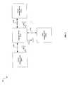
- FIG. 2is a block diagram illustrating a repeater device utilized to forward wireless communications from a source device to a plurality of target devices, in accordance with an embodiment of the invention.
- a source wireless device 202there is shown a source wireless device 202 , target devices 206 1 , . . . , 206 N , a repeater device 204 , transmitted signal 210 , repeated signals 212 1 , . . . , 212 N , and control connections 208 , 209 1 , . . . , 209 N , where N may be the number of target devices to which the signal 210 may be repeated.
- the system 200is only exemplary and other systems may comprise additional source devices, repeater devices, and/or target devices without deviating from the scope of the present invention.
- one or more of the target devices 206 1 , . . . , 206 Nmay comprise suitable logic, circuitry, and/or code that may enable repeating signals.
- one or more of the source wireless device 202 , repeater device 204 , target devices 206 1 , . . . , 206 Nmay comprise suitable logic, circuitry, and/or code that may enable processing of any form of signals such as, for example, multimedia information, comprising, audio, video, and/or data. Audio may comprise voice, any form of music and/or any form of sound.
- the processing of signals by the source wireless device 202 , repeater device 204 , target devices 206 1 , . . . , 206 Nmay occur in analog and/or digital format.
- the source wireless device 202 and the target wireless devices 206 1 , . . . , 206 Nmay each comprise suitable logic, circuitry, and/or code that may enable receiving, transmitting, and processing of RF signals.
- the source wireless device 202 and the target wireless devices 206 1 , . . . , 206 Nmay each comprise the communication subsystem 100 , substantially as described with respect to FIG. 1 .
- the repeater device 204may comprise suitable logic, circuitry, and/or code that may enable reception and/or transmission of an RF signal to facilitate forwarding an RF signal from the source wireless device 202 to target devices 206 1 , . . . , 206 N . Accordingly, the repeater device 204 may be enabled to control directionality of the repeated signals 212 1 , . . . , 212 N so as to direct the signals 212 1 , . . . , 212 N to the target devices 206 1 , . . . , 206 N , respectively. In this regard, repeated signals 212 1 , . . .
- the repeater device 204may each comprise a plurality of signal components and the repeater device 204 may be enabled to control a phase and/or amplitude of the signal components based on the physical location of the target devices 206 1 , . . . , 206 N . Additionally, the repeater device 204 may be enabled to control a frequency of each of the repeated signals 212 1 , . . . , 212 N . Accordingly, to control frequency and/or directionality of repeated signals 212 1 , . . . , 212 N , the repeater device 204 may comprise suitable logic, circuitry, and/or code that may enable configuration of the repeater device 204 based on information received via the control connections 208 , 209 1 , . . . , 209 N .
- the control connections 208 , 209 1 , . . . , 209 Nmay each comprise a wireless and/or wireline link that may be utilized to communicate control messages between the source wireless device 202 and the repeater device 204 , and between the repeater device 204 and the target devices 206 1 , . . . , 206 N , respectively.
- the control connections 208 , 209 1 , . . . , 209 Nmay be utilized to determine the target devices 206 1 , . . . , 206 N for a received signal 210 , determine a receive frequency of each of the target devices 206 1 , . . . , 206 N , and/or determine directionality from the repeater device 204 to each of the target devices 206 1 , . . . , 206 N .
- Exemplary linksmay comprise a Bluetooth connection and a three wire interface.
- the source device 202may transmit a signal 210 destined for the target devices 206 1 , . . . , 206 N .
- signals from the source device 202may not reliably reach one or more of the target devices 206 1 , . . . , 206 N .
- EHFextremely high frequency
- the repeater device 204may receive the signal 210 , having a first frequency, from the source device 202 and repeat (re-transmit) the received signal 210 as signals 212 1 , . . . , 212 N , to the target devices 206 1 , . . .
- the frequency of each of the repeated signals 212 1 , . . . , 212 Nmay be controlled based on the target devices 206 1 , . . . , 206 N and/or based on the environment in which the signals 212 1 , . . . , 212 N may be transmitted.
- the frequency of the received signal 210may be shifted to match the receive frequencies of the target devices 206 1 , . . . , 206 N and/or mitigate any sort of interference such as avoiding noisy frequencies.
- the repeated signals 212 1 , . . . , 212 Nmay be directed to the destination target devices 206 1 , . . .
- the repeated signals 212 1 , . . . , 212 Nmay each comprise a plurality of signal components transmitted via a corresponding plurality of antenna elements and the phase and/or amplitude of the signal components may be controlled to affect the directionality of each of the transmitted signals 212 1 , . . . , 212 N .
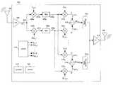
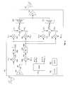
- FIG. 3is a diagram of an exemplary frequency shifting repeater, in accordance with an embodiment of the invention.
- the repeater 204may comprise a low noise amplifier (LNA) 304 ; mixers 306 a , 306 b , 310 1 , . . . , 310 N , and 320 1 , . . . , 320 N ; filters 308 a and 308 b ; adders 312 1 , . . . , 312 N ; power amplifier (PA) 314 ; signal conditioning blocks 322 1 , . . .
- LNAlow noise amplifier
- the repeater 204may comprise or be communicatively coupled to antennas 302 and 316 .
- the antennas 302 and 316may be similar to, or the same as, the antennas 106 a and 106 b , respectively.
- the antennas 302 and 316may each comprise one or more antenna elements and may, for example, comprise a loop antenna, a dipole antenna, or a phased array antenna.
- the LNA 304may comprise suitable logic, circuitry, and/or code that may enable buffering and/or amplification of received RF signals.
- the gain of the LNA 304may be adjustable to enable reception of signals of varying strength.
- the LNA 304may receive one or more control signals from the processor 318 and/or the memory 320 .
- the mixers 306 a and 306 bmay each comprise suitable logic, circuitry, and/or code that may enable generation of inter-modulation products resulting from mixing the received signal RF IN with the in-phase local oscillator (LO) signal I LO — 1 and the quadrature-phase LO signal Q LO — 1 , respectively.
- the mixers 310 k and 320 kmay each comprise suitable logic, circuitry, and/or code that may enable generation of inter-modulation products resulting from mixing the filter outputs 309 a and 309 b with I LO — k and Q LO — k , respectively.
- the filters 308 a and 308 bmay each comprise suitable logic, circuitry, and/or code that may enable passing frequencies at or near a desired intermediate frequency (IF) and attenuating other frequencies.
- the IFmay be given by f 305 ⁇ f LO — 1 , where f 305 may be the frequency of the signal 305 output by the LNA 304 and f LO — 1 may be the frequency of the signals I LO — 1 and Q LO — 1 output by the LOGEN 316 .
- the bandwidth, attenuation, and/or center frequency of each of the filters 308 a and 308 bmay be adjustable based on one or more control signals. Accordingly, the filters 308 a and 308 b may each receive one or more control signals from the processor 318 and/or the memory 320 .
- the adders 312 1 , . . . , 312 Nmay each comprise suitable logic, circuitry, and/or code for adding or subtracting signals.
- the adder 312 kmay be enabled to add signal 311 k to signal 321 k , subtract signal 311 k from signal 321 k and/or subtract signal 311 k from signal 321 k
- the adder 312 kmay receive one or more control signals to determine whether addition or subtraction is performed.
- the selection of addition or subtractionmay depend on the phasing and/or polarity of one or more of the signals I LO — k , Q LO — k , 309 a , and 309 b .
- the PA 314may comprise suitable logic, circuitry, and/or code that may enable buffering and/or amplification of an RF signal and outputting the signal to an antenna for transmission.
- the gain of the PA 314may be adjustable and may enable transmitting signals of varying strength.
- the PA 314may receive one or more control signals from the processor 318 and/or the memory 320 .
- the LOGEN 316may comprise suitable logic, circuitry, and/or code that may enable generating LO signal pairs I LO — 1 , Q LO — 1 , . . . , I LO — N , Q LO — N .
- the signal generator 316may comprise, for example, one or more VCO's, PLLs, and/or direct digital frequency synthesizers (DDFSs).
- the frequency of the LO signals output by the LOGEN 316may be determined based on one or more control signals from the processor 318 and/or the memory 320 .
- the processor 318may be similar to or the same as the processors 108 and/or 110 described with respect to FIG. 1 .
- the processormay be enabled to control operations of the repeater 204 .
- the processor 318may provide one or more control signals for configuring the filters 308 and/or the LOGEN 316 .
- the memory 320may be similar to or the same as the memory 112 described with respect to FIG. 1 .
- the processormay be enabled to store received data and/or information for configuring and/or operating the repeater 304 .
- the memory 320may store information for configuring the filters 308 and/or the LOGEN 316 .
- a signalmay be received via the antenna 302 and amplified by the LNA 304 to generate the signal RF in .
- the mixers 306 a and 306 bmay mix RF in with the LO signal pair I LO — 1 , Q LO — 1 .
- the processor 318 and/or the memory 320may provide one or more signals for controlling the frequency of the LO signal pair I LO — 1 , Q LO — 1 output by the LOGEN 316 .
- the filters 308 a and 308 bmay filter the output of the mixers 306 a and 306 b to generate intermediate frequency (IF) signals 309 a and 309 b .
- IFintermediate frequency
- the processor 318 and/or the memory 320may provide one or more signals for controlling the response of the filters 308 a and 308 b .
- the mixers 310 k and 320 kmay mix the IF signals 309 a and 309 b with the LO signal pair I LO — k , Q LO — k to generate signals 311 k and 311 k .
- the adder 312 kmay add or subtract the signals 311 k and 311 k to generate RF out — k .
- RF out — kmay be generated by frequency shifting RF in by ⁇ (f LO1 +f LOk ), where f LO1 is the frequency of the LO signal pair I LO — 1 , Q LO — 1 and f LOk is the frequency of the LO signal pair I LO — k , Q LO — k output by the LOGEN 316 . Accordingly, signals received via the antenna 302 may be repeated to k target devices on k frequencies via the antenna 316 . Additional details of operation of the repeater 204 may are described below with respect to FIG. 4 .
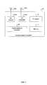
- FIG. 4is a flow chart illustrating exemplary operation of a frequency shifting repeater, in accordance with an embodiment of the invention.
- the exemplary stepsmay begin with step 402 when a signal may be received by the repeater 204 . Subsequent to step 402 , the exemplary steps may advance to step 404 .
- step 404the received RF signal may be amplified by the low noise amplifier 304 . Subsequent to step 404 , the exemplary steps may advance to step 406 .
- the amplified RF signal 305 output by the LNA 304may be quadrature down converted.
- the mixer 306 amay mix the signal 305 with an in-phase local oscillator signal, I LO — 1
- the mixer 306 bmay mix the signal 305 with a quadrature-phase local oscillator signal, Q LO — 1 .
- the exemplary stepsmay advance to step 408 .
- the signals 307 a and 307 b output by the mixers 306 a and 306 bmay be filtered to remove undesired mixer products.
- the filter 308 amay low pass filter the signal 307 a and output cos( ⁇ RF ⁇ LO — 1 ) and the filter 308 b may low pass filter the signal 307 b and output sin( ⁇ RF ⁇ LO — 1 ).
- the exemplary stepsmay advance to step 410 .
- the filtered signals 309 a and 309 bmay be up-converted.
- the mixer 310 kmay mix the signal 309 a with the in-phase local oscillator signal I LO — k signal to generate 311 k and the mixer 320 k may mix the signal 309 b with the quadrature-phase local oscillator signal Q LO — k to generate 321 k .
- the exemplary stepsmay advance to step 412 .
- the adder 312 kmay add or subtract the up-converted signals 311 k and 311 k to generate the RF out — k signal.
- RF out — kmay be frequency shifted relative to the RF in signal by an amount equal to (within a tolerance) ⁇ (f LO — 1 +f LO — k ). For example, if RF in is 61 GHz, f LO — 1 is 250 MHz, and f LO — k is 150 MHz then RF out — k may be 60.6 GHz. In this manner, a received signal may be repeated on a different frequency than the frequency on which it is received.
- the frequency of the transmitted signal 212 kmay be determined based, for example, on a frequency of operation of the target device 206 k and/or noise present in and/or around the repeater 204 . Subsequent to step 412 , the exemplary steps may advance to step 413 .
- the signal RF out — kmay be conditioned by the signal conditioning block 322 k such that the repeated signal 212 k may be directed at the target device 206 k .
- the signal conditioning block 322 kmay adjust a phase and/or amplitude of one or more signal components of the signal RF out — k .
- the exemplary stepsmay advance to step 414 .
- RF out — kmay be amplified by the PA 314 and transmitted via the antenna 316 to the target device 212 k .
- a repeatermay repeat an EHF signal to a plurality of target devices, wherein each of the target devices may be in a different physical location and/or operating on a different frequency.
- a received signal 210may be frequency shifted to generate a plurality of repeated signals 212 , wherein each repeated signal 212 may be frequency shifted by a different frequency with respect to the received signal 210 .
- Each repeated signal 212may comprise one or more signal components and a phase and/or amplitude of each of the components may be controlled, via a signal conditioning block 322 , to control a directivity of the repeated signals.
- Each of the repeated signals 212may be generated by quadrature down-converting said received signal 310 by mixing, via the mixers 306 , the received signal 310 with a first LO signal pair, up-converting the down-converted signal by mixing, via the mixers 310 and 320 , it with a second LO signal pair, and adding or subtracting, via an adder/subtractor 312 , an in-phase portion and a quadrature-phase portion of the up-converted signal.
- a frequency of one or more of the LO signal pairsmay be determined based on a frequency by which one or more of the repeated signals is to be shifted.
- An amount by which to shift the received signalmay be determined based on a receive frequency of a target device 206 for which received signal may be destined and/or based on noise present in a communication medium.
- a plurality of repeated signals 212may be transmitted to a corresponding plurality of target devices 206 .
- one or more target devicesmay receive on a different frequency than one or more other target devices.
- one or more target devices 206may be in a different physical location than one or more other target devices 206 .
- the received signal 210may be repeated a plurality of times en route from a source device 202 to a target device 206 .
- Another embodiment of the inventionmay provide a machine-readable storage, having stored thereon, a computer program having at least one code section executable by a machine, thereby causing the machine to perform the steps as described herein for communicating via spatial multi-link repeater.
- the present inventionmay be realized in hardware, software, or a combination of hardware and software.
- the present inventionmay be realized in a centralized fashion in at least one computer system, or in a distributed fashion where different elements are spread across several interconnected computer systems. Any kind of computer system or other apparatus adapted for carrying out the methods described herein is suited.
- a typical combination of hardware and softwaremay be a general-purpose computer system with a computer program that, when being loaded and executed, controls the computer system such that it carries out the methods described herein.
- the present inventionmay also be embedded in a computer program product, which comprises all the features enabling the implementation of the methods described herein, and which when loaded in a computer system is able to carry out these methods.
- Computer program in the present contextmeans any expression, in any language, code or notation, of a set of instructions intended to cause a system having an information processing capability to perform a particular function either directly or after either or both of the following: a) conversion to another language, code or notation; b) reproduction in a different material form.
Landscapes
- Engineering & Computer Science (AREA)
- Computer Networks & Wireless Communication (AREA)
- Signal Processing (AREA)
- Radio Transmission System (AREA)
- Radio Relay Systems (AREA)
Abstract
Description
- U.S. patent application Ser. No. 12/057,780, filed on Mar. 28, 2008, now published as U.S. patent application publication 2009/0247109;
- U.S. patent application Ser. No. 12/058,077, filed on Mar. 28, 2008, now published as U.S. patent application publication 2009/0247075;
- U.S. patent application Ser. No. 12/116,763, filed on May 7, 2008, now published as U.S. patent application publication 2009/0280768; and
- U.S. patent application Ser. No. 12/116,835, filed on May 7, 2008, now published as U.S. patent application publication 2009/0279593.
Claims (18)
Priority Applications (3)
| Application Number | Priority Date | Filing Date | Title |
|---|---|---|---|
| US12/116,581US8325785B2 (en) | 2008-05-07 | 2008-05-07 | Method and system for communicating via a spatial multilink repeater |
| EP09005844.7AEP2117132B1 (en) | 2008-05-07 | 2009-04-27 | Method and system for communicating via a spatial multilink repeater |
| US13/689,586US8660168B2 (en) | 2008-05-07 | 2012-11-29 | Method and system for communicating via a spatial multilink repeater |
Applications Claiming Priority (1)
| Application Number | Priority Date | Filing Date | Title |
|---|---|---|---|
| US12/116,581US8325785B2 (en) | 2008-05-07 | 2008-05-07 | Method and system for communicating via a spatial multilink repeater |
Related Child Applications (1)
| Application Number | Title | Priority Date | Filing Date |
|---|---|---|---|
| US13/689,586ContinuationUS8660168B2 (en) | 2008-05-07 | 2012-11-29 | Method and system for communicating via a spatial multilink repeater |
Publications (2)
| Publication Number | Publication Date |
|---|---|
| US20090278596A1 US20090278596A1 (en) | 2009-11-12 |
| US8325785B2true US8325785B2 (en) | 2012-12-04 |
Family
ID=40802078
Family Applications (2)
| Application Number | Title | Priority Date | Filing Date |
|---|---|---|---|
| US12/116,581Expired - Fee RelatedUS8325785B2 (en) | 2008-05-07 | 2008-05-07 | Method and system for communicating via a spatial multilink repeater |
| US13/689,586ActiveUS8660168B2 (en) | 2008-05-07 | 2012-11-29 | Method and system for communicating via a spatial multilink repeater |
Family Applications After (1)
| Application Number | Title | Priority Date | Filing Date |
|---|---|---|---|
| US13/689,586ActiveUS8660168B2 (en) | 2008-05-07 | 2012-11-29 | Method and system for communicating via a spatial multilink repeater |
Country Status (2)
| Country | Link |
|---|---|
| US (2) | US8325785B2 (en) |
| EP (1) | EP2117132B1 (en) |
Cited By (1)
| Publication number | Priority date | Publication date | Assignee | Title |
|---|---|---|---|---|
| US9060243B2 (en) | 2013-08-15 | 2015-06-16 | Motorola Solutions, Inc. | Method and apparatus for extending coverage in a wireless communication system |
Families Citing this family (60)
| Publication number | Priority date | Publication date | Assignee | Title |
|---|---|---|---|---|
| US8873585B2 (en) | 2006-12-19 | 2014-10-28 | Corning Optical Communications Wireless Ltd | Distributed antenna system for MIMO technologies |
| WO2009081376A2 (en) | 2007-12-20 | 2009-07-02 | Mobileaccess Networks Ltd. | Extending outdoor location based services and applications into enclosed areas |
| US8090313B2 (en)* | 2008-03-27 | 2012-01-03 | Broadcom Corporation | Method and system for frequency-shift based chip-to-chip communications |
| US8090314B2 (en)* | 2008-03-28 | 2012-01-03 | Broadcom Corporation | Method and system for communicating via a frequency shifting repeater |
| US8116676B2 (en)* | 2008-05-07 | 2012-02-14 | Broadcom Corporation | Method and system for inter IC communications utilizing a spatial multi-link repeater |
| US8295333B2 (en)* | 2008-05-07 | 2012-10-23 | Broadcom Corporation | Method and system for inter-PCB communication utilizing a spatial multi-link repeater |
| US20090316829A1 (en)* | 2008-06-19 | 2009-12-24 | Ahmadreza Rofougaran | Method and system for transmit diversity for chip-to-chip communications |
| US8483623B2 (en)* | 2008-06-19 | 2013-07-09 | Broadcom Corporation | Method and system for frequency-shift based PCB-to-PCB communications |
| EP2344915A4 (en) | 2008-10-09 | 2015-01-21 | Corning Cable Sys Llc | OPTICAL FIBER TERMINAL HAVING AN ADAPTER PANEL HAVING BOTH INPUT AND OUTPUT FIBERS FROM AN OPTICAL DIVIDER |
| US8090315B2 (en)* | 2008-12-24 | 2012-01-03 | Broadcom Corporation | Method and system for frequency control in a frequency shifting repeater |
| AU2010210771B2 (en) | 2009-02-03 | 2015-09-17 | Corning Cable Systems Llc | Optical fiber-based distributed antenna systems, components, and related methods for calibration thereof |
| AU2010210766A1 (en) | 2009-02-03 | 2011-09-15 | Corning Cable Systems Llc | Optical fiber-based distributed antenna systems, components, and related methods for monitoring and configuring thereof |
| US9673904B2 (en) | 2009-02-03 | 2017-06-06 | Corning Optical Communications LLC | Optical fiber-based distributed antenna systems, components, and related methods for calibration thereof |
| US8588686B2 (en)* | 2009-06-09 | 2013-11-19 | Broadcom Corporation | Method and system for remote power distribution and networking for passive devices |
| US8660500B2 (en) | 2009-06-09 | 2014-02-25 | Broadcom Corporation | Method and system for a voltage-controlled oscillator with a leaky wave antenna |
| US9590733B2 (en) | 2009-07-24 | 2017-03-07 | Corning Optical Communications LLC | Location tracking using fiber optic array cables and related systems and methods |
| US8280259B2 (en) | 2009-11-13 | 2012-10-02 | Corning Cable Systems Llc | Radio-over-fiber (RoF) system for protocol-independent wired and/or wireless communication |
| US8275265B2 (en) | 2010-02-15 | 2012-09-25 | Corning Cable Systems Llc | Dynamic cell bonding (DCB) for radio-over-fiber (RoF)-based networks and communication systems and related methods |
| EP2553839A1 (en) | 2010-03-31 | 2013-02-06 | Corning Cable Systems LLC | Localization services in optical fiber-based distributed communications components and systems, and related methods |
| US8570914B2 (en) | 2010-08-09 | 2013-10-29 | Corning Cable Systems Llc | Apparatuses, systems, and methods for determining location of a mobile device(s) in a distributed antenna system(s) |
| US9252874B2 (en) | 2010-10-13 | 2016-02-02 | Ccs Technology, Inc | Power management for remote antenna units in distributed antenna systems |
| US9720197B2 (en) | 2010-10-19 | 2017-08-01 | Corning Optical Communications LLC | Transition box for multiple dwelling unit fiber optic distribution network |
| CN103548290B (en) | 2011-04-29 | 2016-08-31 | 康宁光缆系统有限责任公司 | Judge the communication propagation delays in distributing antenna system and associated component, System and method for |
| EP2702780A4 (en) | 2011-04-29 | 2014-11-12 | Corning Cable Sys Llc | Systems, methods, and devices for increasing radio frequency (rf) power in distributed antenna systems |
| US9219546B2 (en) | 2011-12-12 | 2015-12-22 | Corning Optical Communications LLC | Extremely high frequency (EHF) distributed antenna systems, and related components and methods |
| US10110307B2 (en) | 2012-03-02 | 2018-10-23 | Corning Optical Communications LLC | Optical network units (ONUs) for high bandwidth connectivity, and related components and methods |
| EP2832012A1 (en) | 2012-03-30 | 2015-02-04 | Corning Optical Communications LLC | Reducing location-dependent interference in distributed antenna systems operating in multiple-input, multiple-output (mimo) configuration, and related components, systems, and methods |
| US9781553B2 (en) | 2012-04-24 | 2017-10-03 | Corning Optical Communications LLC | Location based services in a distributed communication system, and related components and methods |
| WO2013162988A1 (en) | 2012-04-25 | 2013-10-31 | Corning Cable Systems Llc | Distributed antenna system architectures |
| WO2014024192A1 (en) | 2012-08-07 | 2014-02-13 | Corning Mobile Access Ltd. | Distribution of time-division multiplexed (tdm) management services in a distributed antenna system, and related components, systems, and methods |
| US9455784B2 (en) | 2012-10-31 | 2016-09-27 | Corning Optical Communications Wireless Ltd | Deployable wireless infrastructures and methods of deploying wireless infrastructures |
| EP2926466A1 (en) | 2012-11-29 | 2015-10-07 | Corning Optical Communications LLC | HYBRID INTRA-CELL / INTER-CELL REMOTE UNIT ANTENNA BONDING IN MULTIPLE-INPUT, MULTIPLE-OUTPUT (MIMO) DISTRIBUTED ANTENNA SYSTEMS (DASs) |
| US9647758B2 (en) | 2012-11-30 | 2017-05-09 | Corning Optical Communications Wireless Ltd | Cabling connectivity monitoring and verification |
| US9158864B2 (en) | 2012-12-21 | 2015-10-13 | Corning Optical Communications Wireless Ltd | Systems, methods, and devices for documenting a location of installed equipment |
| WO2014199380A1 (en) | 2013-06-12 | 2014-12-18 | Corning Optical Communications Wireless, Ltd. | Time-division duplexing (tdd) in distributed communications systems, including distributed antenna systems (dass) |
| EP3008515A1 (en) | 2013-06-12 | 2016-04-20 | Corning Optical Communications Wireless, Ltd | Voltage controlled optical directional coupler |
| US9247543B2 (en) | 2013-07-23 | 2016-01-26 | Corning Optical Communications Wireless Ltd | Monitoring non-supported wireless spectrum within coverage areas of distributed antenna systems (DASs) |
| US9661781B2 (en) | 2013-07-31 | 2017-05-23 | Corning Optical Communications Wireless Ltd | Remote units for distributed communication systems and related installation methods and apparatuses |
| US9385810B2 (en) | 2013-09-30 | 2016-07-05 | Corning Optical Communications Wireless Ltd | Connection mapping in distributed communication systems |
| US9178635B2 (en) | 2014-01-03 | 2015-11-03 | Corning Optical Communications Wireless Ltd | Separation of communication signal sub-bands in distributed antenna systems (DASs) to reduce interference |
| US9973362B2 (en)* | 2014-03-07 | 2018-05-15 | Huawei Technologies Co., Ltd. | Common broadcast channel low PAPR signaling in massive MIMO systems |
| US9775123B2 (en) | 2014-03-28 | 2017-09-26 | Corning Optical Communications Wireless Ltd. | Individualized gain control of uplink paths in remote units in a distributed antenna system (DAS) based on individual remote unit contribution to combined uplink power |
| US9357551B2 (en) | 2014-05-30 | 2016-05-31 | Corning Optical Communications Wireless Ltd | Systems and methods for simultaneous sampling of serial digital data streams from multiple analog-to-digital converters (ADCS), including in distributed antenna systems |
| US9525472B2 (en) | 2014-07-30 | 2016-12-20 | Corning Incorporated | Reducing location-dependent destructive interference in distributed antenna systems (DASS) operating in multiple-input, multiple-output (MIMO) configuration, and related components, systems, and methods |
| US9730228B2 (en) | 2014-08-29 | 2017-08-08 | Corning Optical Communications Wireless Ltd | Individualized gain control of remote uplink band paths in a remote unit in a distributed antenna system (DAS), based on combined uplink power level in the remote unit |
| US9602210B2 (en) | 2014-09-24 | 2017-03-21 | Corning Optical Communications Wireless Ltd | Flexible head-end chassis supporting automatic identification and interconnection of radio interface modules and optical interface modules in an optical fiber-based distributed antenna system (DAS) |
| US9420542B2 (en) | 2014-09-25 | 2016-08-16 | Corning Optical Communications Wireless Ltd | System-wide uplink band gain control in a distributed antenna system (DAS), based on per band gain control of remote uplink paths in remote units |
| US9729267B2 (en) | 2014-12-11 | 2017-08-08 | Corning Optical Communications Wireless Ltd | Multiplexing two separate optical links with the same wavelength using asymmetric combining and splitting |
| US20160249365A1 (en) | 2015-02-19 | 2016-08-25 | Corning Optical Communications Wireless Ltd. | Offsetting unwanted downlink interference signals in an uplink path in a distributed antenna system (das) |
| US9681313B2 (en) | 2015-04-15 | 2017-06-13 | Corning Optical Communications Wireless Ltd | Optimizing remote antenna unit performance using an alternative data channel |
| US9948349B2 (en) | 2015-07-17 | 2018-04-17 | Corning Optical Communications Wireless Ltd | IOT automation and data collection system |
| US10560214B2 (en) | 2015-09-28 | 2020-02-11 | Corning Optical Communications LLC | Downlink and uplink communication path switching in a time-division duplex (TDD) distributed antenna system (DAS) |
| US9648580B1 (en) | 2016-03-23 | 2017-05-09 | Corning Optical Communications Wireless Ltd | Identifying remote units in a wireless distribution system (WDS) based on assigned unique temporal delay patterns |
| US10236924B2 (en) | 2016-03-31 | 2019-03-19 | Corning Optical Communications Wireless Ltd | Reducing out-of-channel noise in a wireless distribution system (WDS) |
| US11101842B2 (en)* | 2019-04-18 | 2021-08-24 | Qualcomm Incorporated | Interference mitigation techniques in directional beamforming repeaters |
| US11792833B2 (en)* | 2019-05-14 | 2023-10-17 | Qualcomm Incorporated | Analog phased-array repeaters with digitally-assisted frequency translation and phase adjustment |
| US11792063B2 (en)* | 2019-05-14 | 2023-10-17 | Qualcomm Incorporated | Techniques for phase rotation correction |
| US11368209B2 (en)* | 2019-05-30 | 2022-06-21 | Qualcomm Incorporated | Methods and apparatus for frequency translating repeaters |
| US11848654B2 (en)* | 2019-06-05 | 2023-12-19 | Wilson Electronics, Llc | Power amplifier (PA)-filter output power tuning |
| WO2024064124A2 (en)* | 2022-09-20 | 2024-03-28 | Apple Inc. | Radio access technology (rat) spectrum translator |
Citations (12)
| Publication number | Priority date | Publication date | Assignee | Title |
|---|---|---|---|---|
| US5200955A (en) | 1988-04-22 | 1993-04-06 | British Telecommunications Public Limited Company | Repeater for tdma mobile radio |
| US6697603B1 (en)* | 1999-12-13 | 2004-02-24 | Andrew Corporation | Digital repeater |
| US20060019604A1 (en)* | 2002-06-20 | 2006-01-26 | Dekolink Wireless Ltd. | System and method for excluding narrow band noise from a communication channel |
| US20090247213A1 (en) | 2008-03-27 | 2009-10-01 | Ahmadreza Rofougaran | Method and system for frequency-shift based chip-to-chip communications |
| US20090247109A1 (en) | 2008-03-28 | 2009-10-01 | Ahmadreza Rofougaran | Method and system for communicating via a frequency shifting repeater |
| US20090279593A1 (en) | 2008-05-07 | 2009-11-12 | Ahmadreza Rofougaran | Method And System For Inter-PCB Communication Utilizing A Spatial Multi-Link Repeater |
| US20090280768A1 (en) | 2008-05-07 | 2009-11-12 | Ahmadreza Rofougaran | Method And System For Inter IC Communications Utilizing A Spatial Multi-Link Repeater |
| US20090318086A1 (en) | 2008-06-19 | 2009-12-24 | Ahmadreza Rofougaran | Method and system for frequency-shift based pcb-to-pcb communications |
| US20090316829A1 (en) | 2008-06-19 | 2009-12-24 | Ahmadreza Rofougaran | Method and system for transmit diversity for chip-to-chip communications |
| US20100159859A1 (en) | 2008-12-24 | 2010-06-24 | Ahmadreza Rofougaran | Method and system for frequency control in a frequency shifting repeater |
| US7764924B1 (en)* | 2007-05-25 | 2010-07-27 | Sprint Spectrum L.P. | Method and system for repeater shutdown based on received power |
| US7813451B2 (en) | 2006-01-11 | 2010-10-12 | Mobileaccess Networks Ltd. | Apparatus and method for frequency shifting of a wireless signal and systems using frequency shifting |
Family Cites Families (2)
| Publication number | Priority date | Publication date | Assignee | Title |
|---|---|---|---|---|
| US5619503A (en)* | 1994-01-11 | 1997-04-08 | Ericsson Inc. | Cellular/satellite communications system with improved frequency re-use |
| BR0316218A (en)* | 2002-11-15 | 2005-09-27 | Widefi Inc | Method and apparatus for detecting the presence of a signal on one of at least two frequency channels in a frequency translation repeater for use in a wireless local area network (WLAN) |
- 2008
- 2008-05-07USUS12/116,581patent/US8325785B2/ennot_activeExpired - Fee Related
- 2009
- 2009-04-27EPEP09005844.7Apatent/EP2117132B1/enactiveActive
- 2012
- 2012-11-29USUS13/689,586patent/US8660168B2/enactiveActive
Patent Citations (12)
| Publication number | Priority date | Publication date | Assignee | Title |
|---|---|---|---|---|
| US5200955A (en) | 1988-04-22 | 1993-04-06 | British Telecommunications Public Limited Company | Repeater for tdma mobile radio |
| US6697603B1 (en)* | 1999-12-13 | 2004-02-24 | Andrew Corporation | Digital repeater |
| US20060019604A1 (en)* | 2002-06-20 | 2006-01-26 | Dekolink Wireless Ltd. | System and method for excluding narrow band noise from a communication channel |
| US7813451B2 (en) | 2006-01-11 | 2010-10-12 | Mobileaccess Networks Ltd. | Apparatus and method for frequency shifting of a wireless signal and systems using frequency shifting |
| US7764924B1 (en)* | 2007-05-25 | 2010-07-27 | Sprint Spectrum L.P. | Method and system for repeater shutdown based on received power |
| US20090247213A1 (en) | 2008-03-27 | 2009-10-01 | Ahmadreza Rofougaran | Method and system for frequency-shift based chip-to-chip communications |
| US20090247109A1 (en) | 2008-03-28 | 2009-10-01 | Ahmadreza Rofougaran | Method and system for communicating via a frequency shifting repeater |
| US20090279593A1 (en) | 2008-05-07 | 2009-11-12 | Ahmadreza Rofougaran | Method And System For Inter-PCB Communication Utilizing A Spatial Multi-Link Repeater |
| US20090280768A1 (en) | 2008-05-07 | 2009-11-12 | Ahmadreza Rofougaran | Method And System For Inter IC Communications Utilizing A Spatial Multi-Link Repeater |
| US20090318086A1 (en) | 2008-06-19 | 2009-12-24 | Ahmadreza Rofougaran | Method and system for frequency-shift based pcb-to-pcb communications |
| US20090316829A1 (en) | 2008-06-19 | 2009-12-24 | Ahmadreza Rofougaran | Method and system for transmit diversity for chip-to-chip communications |
| US20100159859A1 (en) | 2008-12-24 | 2010-06-24 | Ahmadreza Rofougaran | Method and system for frequency control in a frequency shifting repeater |
Cited By (1)
| Publication number | Priority date | Publication date | Assignee | Title |
|---|---|---|---|---|
| US9060243B2 (en) | 2013-08-15 | 2015-06-16 | Motorola Solutions, Inc. | Method and apparatus for extending coverage in a wireless communication system |
Also Published As
| Publication number | Publication date |
|---|---|
| EP2117132A2 (en) | 2009-11-11 |
| US8660168B2 (en) | 2014-02-25 |
| US20130083828A1 (en) | 2013-04-04 |
| US20090278596A1 (en) | 2009-11-12 |
| EP2117132B1 (en) | 2021-03-17 |
| EP2117132A3 (en) | 2014-05-21 |
Similar Documents
| Publication | Publication Date | Title |
|---|---|---|
| US8325785B2 (en) | Method and system for communicating via a spatial multilink repeater | |
| US8295333B2 (en) | Method and system for inter-PCB communication utilizing a spatial multi-link repeater | |
| US8090314B2 (en) | Method and system for communicating via a frequency shifting repeater | |
| US8396417B2 (en) | Frequency shifting repeater | |
| US8244175B2 (en) | Method and system for signal repeater with gain control and spatial isolation | |
| US8023886B2 (en) | Method and system for repeater with gain control and isolation via polarization | |
| US7881753B2 (en) | Method and system for sharing multiple antennas between TX and RX in a repeat field of polarization isolation | |
| TW441203B (en) | Wireless communication system, transmitter and receiver | |
| US8116676B2 (en) | Method and system for inter IC communications utilizing a spatial multi-link repeater | |
| EP2437571B1 (en) | Method and system for 60 GHz distributed communication | |
| US8160525B2 (en) | Method and system for compensating for using a transmitter to calibrate a receiver for channel equalization | |
| US8942646B2 (en) | Method and system for a 60 GHz communication device comprising multi-location antennas for pseudo-beamforming | |
| US8090313B2 (en) | Method and system for frequency-shift based chip-to-chip communications | |
| US8483623B2 (en) | Method and system for frequency-shift based PCB-to-PCB communications | |
| US8977219B2 (en) | Method and system for mitigating leakage of a 60 GHz transmitted signal back into an RF input of a 60 GHz device | |
| US9979461B2 (en) | RF repeater | |
| US7865138B2 (en) | Method and system for a low-complexity multi-beam repeater | |
| US9591695B2 (en) | Method and system for sharing modulation information between multiple access points | |
| HK1167945A (en) | Method and system for 60 ghz distributed communication | |
| HK1173571A (en) | Method and system for 60 ghz distributed communication |
Legal Events
| Date | Code | Title | Description |
|---|---|---|---|
| AS | Assignment | Owner name:BROADCOM CORPORATION, CALIFORNIA Free format text:ASSIGNMENT OF ASSIGNORS INTEREST;ASSIGNORS:ROFOUGARAN, AHMADREZA;ROFOUGARAN, MARYAM;REEL/FRAME:020960/0880 Effective date:20080505 | |
| ZAAA | Notice of allowance and fees due | Free format text:ORIGINAL CODE: NOA | |
| ZAAB | Notice of allowance mailed | Free format text:ORIGINAL CODE: MN/=. | |
| STCF | Information on status: patent grant | Free format text:PATENTED CASE | |
| AS | Assignment | Owner name:BANK OF AMERICA, N.A., AS COLLATERAL AGENT, NORTH CAROLINA Free format text:PATENT SECURITY AGREEMENT;ASSIGNOR:BROADCOM CORPORATION;REEL/FRAME:037806/0001 Effective date:20160201 Owner name:BANK OF AMERICA, N.A., AS COLLATERAL AGENT, NORTH Free format text:PATENT SECURITY AGREEMENT;ASSIGNOR:BROADCOM CORPORATION;REEL/FRAME:037806/0001 Effective date:20160201 | |
| FPAY | Fee payment | Year of fee payment:4 | |
| AS | Assignment | Owner name:AVAGO TECHNOLOGIES GENERAL IP (SINGAPORE) PTE. LTD., SINGAPORE Free format text:ASSIGNMENT OF ASSIGNORS INTEREST;ASSIGNOR:BROADCOM CORPORATION;REEL/FRAME:041706/0001 Effective date:20170120 Owner name:AVAGO TECHNOLOGIES GENERAL IP (SINGAPORE) PTE. LTD Free format text:ASSIGNMENT OF ASSIGNORS INTEREST;ASSIGNOR:BROADCOM CORPORATION;REEL/FRAME:041706/0001 Effective date:20170120 | |
| AS | Assignment | Owner name:BROADCOM CORPORATION, CALIFORNIA Free format text:TERMINATION AND RELEASE OF SECURITY INTEREST IN PATENTS;ASSIGNOR:BANK OF AMERICA, N.A., AS COLLATERAL AGENT;REEL/FRAME:041712/0001 Effective date:20170119 | |
| AS | Assignment | Owner name:AVAGO TECHNOLOGIES INTERNATIONAL SALES PTE. LIMITE Free format text:MERGER;ASSIGNOR:AVAGO TECHNOLOGIES GENERAL IP (SINGAPORE) PTE. LTD.;REEL/FRAME:047230/0133 Effective date:20180509 | |
| AS | Assignment | Owner name:AVAGO TECHNOLOGIES INTERNATIONAL SALES PTE. LIMITE Free format text:CORRECTIVE ASSIGNMENT TO CORRECT THE EFFECTIVE DATE OF MERGER TO 09/05/2018 PREVIOUSLY RECORDED AT REEL: 047230 FRAME: 0133. ASSIGNOR(S) HEREBY CONFIRMS THE MERGER;ASSIGNOR:AVAGO TECHNOLOGIES GENERAL IP (SINGAPORE) PTE. LTD.;REEL/FRAME:047630/0456 Effective date:20180905 | |
| MAFP | Maintenance fee payment | Free format text:PAYMENT OF MAINTENANCE FEE, 8TH YEAR, LARGE ENTITY (ORIGINAL EVENT CODE: M1552); ENTITY STATUS OF PATENT OWNER: LARGE ENTITY Year of fee payment:8 | |
| FEPP | Fee payment procedure | Free format text:MAINTENANCE FEE REMINDER MAILED (ORIGINAL EVENT CODE: REM.); ENTITY STATUS OF PATENT OWNER: LARGE ENTITY | |
| LAPS | Lapse for failure to pay maintenance fees | Free format text:PATENT EXPIRED FOR FAILURE TO PAY MAINTENANCE FEES (ORIGINAL EVENT CODE: EXP.); ENTITY STATUS OF PATENT OWNER: LARGE ENTITY | |
| STCH | Information on status: patent discontinuation | Free format text:PATENT EXPIRED DUE TO NONPAYMENT OF MAINTENANCE FEES UNDER 37 CFR 1.362 | |
| FP | Lapsed due to failure to pay maintenance fee | Effective date:20241204 |