US8324830B2 - Color management for field-sequential LCD display - Google Patents
Color management for field-sequential LCD displayDownload PDFInfo
- Publication number
- US8324830B2 US8324830B2US12/695,191US69519110AUS8324830B2US 8324830 B2US8324830 B2US 8324830B2US 69519110 AUS69519110 AUS 69519110AUS 8324830 B2US8324830 B2US 8324830B2
- Authority
- US
- United States
- Prior art keywords
- led strings
- color
- indication
- colored led
- frame
- Prior art date
- Legal status (The legal status is an assumption and is not a legal conclusion. Google has not performed a legal analysis and makes no representation as to the accuracy of the status listed.)
- Expired - Fee Related, expires
Links
Images


Classifications
- H—ELECTRICITY
- H05—ELECTRIC TECHNIQUES NOT OTHERWISE PROVIDED FOR
- H05B—ELECTRIC HEATING; ELECTRIC LIGHT SOURCES NOT OTHERWISE PROVIDED FOR; CIRCUIT ARRANGEMENTS FOR ELECTRIC LIGHT SOURCES, IN GENERAL
- H05B45/00—Circuit arrangements for operating light-emitting diodes [LED]
- H05B45/20—Controlling the colour of the light
- H05B45/22—Controlling the colour of the light using optical feedback
- H—ELECTRICITY
- H05—ELECTRIC TECHNIQUES NOT OTHERWISE PROVIDED FOR
- H05B—ELECTRIC HEATING; ELECTRIC LIGHT SOURCES NOT OTHERWISE PROVIDED FOR; CIRCUIT ARRANGEMENTS FOR ELECTRIC LIGHT SOURCES, IN GENERAL
- H05B47/00—Circuit arrangements for operating light sources in general, i.e. where the type of light source is not relevant
- H05B47/10—Controlling the light source
- H05B47/105—Controlling the light source in response to determined parameters
- H05B47/11—Controlling the light source in response to determined parameters by determining the brightness or colour temperature of ambient light
- Y—GENERAL TAGGING OF NEW TECHNOLOGICAL DEVELOPMENTS; GENERAL TAGGING OF CROSS-SECTIONAL TECHNOLOGIES SPANNING OVER SEVERAL SECTIONS OF THE IPC; TECHNICAL SUBJECTS COVERED BY FORMER USPC CROSS-REFERENCE ART COLLECTIONS [XRACs] AND DIGESTS
- Y02—TECHNOLOGIES OR APPLICATIONS FOR MITIGATION OR ADAPTATION AGAINST CLIMATE CHANGE
- Y02B—CLIMATE CHANGE MITIGATION TECHNOLOGIES RELATED TO BUILDINGS, e.g. HOUSING, HOUSE APPLIANCES OR RELATED END-USER APPLICATIONS
- Y02B20/00—Energy efficient lighting technologies, e.g. halogen lamps or gas discharge lamps
- Y02B20/30—Semiconductor lamps, e.g. solid state lamps [SSL] light emitting diodes [LED] or organic LED [OLED]
- Y—GENERAL TAGGING OF NEW TECHNOLOGICAL DEVELOPMENTS; GENERAL TAGGING OF CROSS-SECTIONAL TECHNOLOGIES SPANNING OVER SEVERAL SECTIONS OF THE IPC; TECHNICAL SUBJECTS COVERED BY FORMER USPC CROSS-REFERENCE ART COLLECTIONS [XRACs] AND DIGESTS
- Y02—TECHNOLOGIES OR APPLICATIONS FOR MITIGATION OR ADAPTATION AGAINST CLIMATE CHANGE
- Y02B—CLIMATE CHANGE MITIGATION TECHNOLOGIES RELATED TO BUILDINGS, e.g. HOUSING, HOUSE APPLIANCES OR RELATED END-USER APPLICATIONS
- Y02B20/00—Energy efficient lighting technologies, e.g. halogen lamps or gas discharge lamps
- Y02B20/40—Control techniques providing energy savings, e.g. smart controller or presence detection
Definitions
- the present inventiongenerally relates to the field of lighting and more particularly to a color manager in cooperation with a color sensor arranged to control the color and luminance of a field-sequential display responsive to an ambient light condition.
- LEDs with an overall high luminanceare useful in backlighting for Liquid Crystal Display (LCD) based monitors and televisions, collectively hereinafter referred to as a matrix display.
- LCDLiquid Crystal Display
- Matrix displaystypically display the image as a series of frames, with the information for the display being drawn from left to right in a series of descending lines during the frame.
- one of field-sequential lighting and non-field-sequential backlightingis employed.
- non-field-sequential backlightingeither one or more strings of “white” LEDs are utilized as a luminaire, the white LEDs typically comprising a blue LED with a phosphor, which absorbs the blue light emitted by the LED to emit a white light, or one or more individual strings of colored LEDs, functioning as a luminaire, are placed in proximity so that in combination their light is seen as white light.
- colored LED stringsare exclusively utilized, and the colored LED strings typically are lit sequentially. The LCD is synchronized with the sequential lighting of the colored LED strings.
- a field sequential systemadvantageously does not require color filters for each of the pixels, since the color is directly supplied by the backlight LEDs. As a result, an increased percentage of the light produced by the backlight LEDs is transmitted through the LCD and perceived by the viewer. Unfortunately, this advantage leads to certain difficulties in color control.
- the human eyehas receptors responsive to different wavelengths of light.
- three different types of receptorsare typically found, each associated with a certain wavelength.
- the three valuesmay be described in any of a plurality of color spaces, also known as colorimetric systems, which may be standardized color spaces such as the CIE 1931 color space, or an RGB color space associated with a particular color sensor.
- Translation between color spacesis typically accomplished mathematically, with translation between standardized color spaces being accomplished in cooperation with known fixed values, and translation between particular color spaces and standardized color spaces typically requiring certain calibration information.
- tri-stimulus values as used herein,is meant to include any set of values which represent the luminance and chromaticity of a color sensation, in any color space.
- colored LEDschange their luminance and hue characteristics as a function of age and temperature.
- a color sensoris thus provided, in optical communication with the source lighting.
- the output of the color sensoris fedback to a controller or manager, which is operative to adjust the drive signals of the respective colored LEDs so as to achieve a pre-determined color temperature.
- ambient lightis similarly strongly attenuated prior to reaching the color sensor. As a result, changes in ambient light do not currently significantly impact the color control of a non-field-sequential backlight.
- the color of the ambient lightimpacts the chromaticity values of the color control loop.
- the color control loopwill reduce the color components associated with ambient light hue. This is similarly unfortunate, as the resultant colors associated with the ambient light hue will be washed out.
- the present disclosureprovides methods and apparatus to overcome some or all of the disadvantages of prior and present field-sequential color control methods and apparatuses.
- Other new and useful advantages of the present methods and apparatuswill also be described herein and can be appreciated by those skilled in the art.
- a color control systemfor a field sequential backlight utilizing colored light emitting diodes (LEDs), the color control system comprising: a color controller; an LED driver responsive to the color controller; a plurality of colored LED strings constituted of at least three different colors responsive to the LED driver; and a color sensor, exhibiting a tri-stimulus output, in optical communication with the plurality of colored LED strings, the color controller coupled to the tri-stimulus output of the color sensor, wherein the color controller is operative to: light each of the plurality of colored LED strings via the LED driver; provide a period wherein none of the colored LED strings are lit; receive from the color sensor, during the provided period when none of the colored LED strings are lit, an indication of an ambient light received at the color sensor; receive from the color sensor, during the provided period when the colored LED strings are lit, an indication of the optical output of the colored LED strings; and control the LED driver responsive to the received indication of ambient light and the received indication of the output of the colored LED strings.
- LEDscolored light emitting diodes
- the lighting of the plurality of colored LED strings and the received indication of the optical output of the colored LED stringsis sequential, and the indication of the optical output of the colored LED strings is an indication of the optical output of each color of the colored LED strings.
- FIG. 1illustrates a high level schematic diagram of an exemplary first embodiment of a color control system comprising a color controller exhibiting a calibration matrix functionality and a compensation functionality, the calibration matrix functionality arranged to receive from a color sensor both samples of ambient light and light from the colored LED strings;
- FIG. 2illustrates a high level schematic diagram of an exemplary second embodiment of a color control system comprising a color controller exhibiting a calibration matrix functionality and a compensation functionality, the compensation functionality arranged to receive from a color sensor both samples of ambient light and light from the colored LED strings;
- FIG. 3illustrates a timing diagram of an exemplary embodiment of field-sequential lighting operation for the embodiments of FIGS. 1 and 2 ;
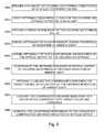
- FIGS. 4-6illustrate high level flow charts of various exemplary embodiments of a method of color control with compensation for ambient lighting.
- FIG. 1illustrates a high level schematic diagram of an exemplary first embodiment of a color control system 5 comprising a color controller exhibiting a calibration matrix functionality and a compensation functionality, the calibration matrix functionality arranged to receive from a color sensor both samples of ambient light and light from the colored LED strings.
- color control system 5comprises: a color sensor 10 exhibiting a tri-stimulus output; an optional low pass filter (LPF) 20 ; a color controller 25 ; an LED driver 90 ; a plurality of different colored LED strings generally denoted 100 , illustrated as a red LED string 100 R, a green LED string 100 G and a blue LED string 100 B; a light guide 110 ; and an LCD 120 .
- FIG. 1illustrates a high level schematic diagram of an exemplary first embodiment of a color control system 5 comprising a color controller exhibiting a calibration matrix functionality and a compensation functionality, the calibration matrix functionality arranged to receive from a color sensor both samples of ambient light and light from the colored LED strings.
- color control system 5comprises: a
- Color controller 25comprises: an A/D converter 30 ; a calibration matrix functionality 40 ; a compensation functionality 50 ; a source of target color and luminance information 60 ; a difference generator functionality 70 ; and a feedback controller functionality 80 .
- Color sensor 10is arranged to receive light from light guide 110 comprising light from each of red LED string 100 R, green LED string 100 G and blue LED string 100 B and a portion of ambient light from ambient light source 130 , the portion of ambient light received may be directed by light guide 110 or directly impinge on color sensor 10 .
- the tri-stimulus outputs of color sensor 10are passed through optional low pass filter 20 to the respective inputs of A/D converter 30 .
- the tri-stimulus outputs of A/D converter 30are connected to respective inputs of calibration matrix functionality 40 , and the tri-stimulus output of calibration matrix functionality 40 are connected to respective inputs of compensation functionality 50 .
- the tri-stimulus outputs of compensation functionality 50are connected to respective first inputs of difference generator functionality 70 , and the tri-stimulus outputs of source of target color and luminance information 60 are connected to respective second inputs of difference generator functionality 70 .
- the outputs of difference generator functionality 70are connected to respective inputs of feedback controller functionality 80 , and the outputs of feedback controller functionality 80 are fed to respective inputs of LED driver 90 .
- the outputs of LED driver 90are respectively connected to the inputs of red LED string 100 R, green LED string 100 G and blue LED string 100 B.
- Light guide 110is arranged to receive the optical outputs of red LED string 100 R, green LED string 100 G and blue LED string 100 B and guide the optical outputs to light LCD 120 so that information displayed thereon is visible to viewer 140 .
- any and all of optional low pass filter 20 , A/D converter 30 , calibration matrix functionality 40 , compensation functionality 50 , source of target color and luminance information 60 , difference generator functionality 70 , feedback controller functionality 80 and LED driver 90may be implemented in a single unit, as part of a microcontroller or field programmable gate array.
- color controller 25further comprises optional LPF 20 instituted digitally responsive to the output of A/D converter 30 .
- color controller 25further comprises LED driver 90 .
- source of target color and luminance information 60is supplied by a separate video controller, and in another embodiment source of target color and luminance information 60 is stored in local registers.
- LED driver 90is constituted of a pulse width modulation (PWM) functionality.
- PWMpulse width modulation
- feedback controller functionality 80comprises a proportional integral (PI) controller
- feedback controller functionality 80comprises a proportion integral differential (PID) controller
- optional LPF 20is replaced with an integrator as described in pending patent application Ser. No. 12/136,095 entitled “Optical Sampling and Control Element”, published Jan. 1, 2009 to Blaut et at as US 2009/0001253 A1, the entire contents of which are incorporated herein by reference.
- a periodis provided by LED driver 90 wherein none of colored LED strings 100 are lit.
- the output of color sensor 10which during this provided period represents only the impact of light arriving from ambient light source 130 , is sampled via A/D converter 30 during the provided period.
- a plurality of periodsmay be provided by LED driver 90 in each frame wherein none of colored LED strings 100 are lit, and in an exemplary embodiment an average of the periods is used.
- Calibration matrix functionality 40is operative to convert the tri-stimulus values output by color sensor 10 representative of the impact of light arriving from ambient light source 130 to a color space consonant with the color space of the output of source of target color and luminance information 60 .
- the operation of calibration matrix 40can in one embodiment be represented as:
- [ R G B ]represents the tri-stimulus output of color sensor 10 sampled during the provided period when none of colored LED strings 100 are lit
- [C]is a calibration matrix defined to convert the tri-stimulus values output by color sensor 10 to a color space consonant with the color space of the output of source of target color and luminance information 60 .
- calibration matrix [C]is defined at a particular operating point for colored LED strings 100 .
- a plurality of calibration matrixes [C]are provided, each associated with a particular temperature or current level. Mathematically, [C] may be expressed as:
- the vector result of EQ. 1thus represents the impact of light arriving from ambient light source 130 received at color sensor 10 .
- color control system 5is operated as a field-sequential system as will be described in relation to FIG. 3 , wherein each of the colored LED strings 100 are operated at a unique time during the frame. Operation of color control system 5 will now be described in relation to operation as a field-sequential system, however this is not meant to be limiting in any way, and is equally applicable to a non-field-sequential based system.
- FIG. 3illustrates a timing diagram of a single frame of the operation of color control system 5 when operated as a field-sequential system, wherein the x-axis represents time periods during the single shown frame.
- LCD 120performs setup of the pixels thereon for the period when red LED string 100 R is to be lit, the period being denoted SETUP RED. It is to be noted that during the setup time for red LED string 100 R, no colored LED strings 100 are lit, thus providing the period described above in relation to EQ. 1 wherein none of colored LED strings 100 are lit. After the expiration of the setup time, red LED string 100 R is lit.
- the output of color sensor 10is sampled, the period being denoted LIGHT RED.
- the tri-stimulus values sampled during period LIGHT REDare converted by calibration matrix functionality 40 as described above in relation to EQ. 1 to a color space consonant with the color space of the output of source of target color and luminance information 60 , described mathematically in one embodiment as:
- LCD 120After expiration of the period when red LED string 100 R is lit, LCD 120 performs setup of the pixels thereon for the period when green LED string 100 G is to be lit. It is to be noted that during the setup time for green LED string 100 G, no colored LED strings 100 are lit, thus providing the period described above in relation to EQ. 1 wherein none of colored LED strings 100 are lit, the period being denoted SETUP GREEN. After the expiration of the setup time, green LED string 100 G is lit. During the period when green LED string 100 G is lit, the output of color sensor 10 is sampled, the period being denoted LIGHT GREEN. The tri-stimulus sampled values during period LIGHT GREEN are converted by calibration matrix functionality 40 as described above in relation to EQ. 1 to a color space consonant with the color space of the output of source of target color and luminance information 60 , described mathematically in one embodiment as:
- LCD 120After expiration of the period when green LED string 100 G is lit, LCD 120 performs setup of the pixels thereon for the period when blue LED string 100 B is to be lit. It is to be noted that during the setup time for blue LED string 100 B, no colored LED strings 100 are lit, thus providing the period described above in relation to EQ. 1 wherein none of colored LED strings 100 are lit, the period being denoted SETUP BLUE. After the expiration of the setup time, blue LED string 100 B is lit. During the period when blue LED string 100 B is lit, the output of color sensor 10 is sampled, the period being denoted LIGHT BLUE. The tri-stimulus sampled values during the period LIGHT BLUE are converted by calibration matrix functionality 40 as described above in relation to EQ. 1 to a color space consonant with the color space of the output of source of target color and luminance information 60 , described mathematically in one embodiment as:
- Compensation functionality 50is operative, preferably once per frame, to calculate combined color coordinates of colored LED strings 100 , including the impact of ambient light source 130 .
- the operation of compensation functionality 50 to calculate combined color coordinatesis in one embodiment described as:
- [ Xsampled Ysampled Zsampled ][ Xr Yr Zr ] + [ Xg Yg Zg ] + [ Xb Yb Zb ] . EQ . ⁇ 5
- [ Xsampled Ysampled Zsampled ]are directly derived from samples of colored LED strings 100 during joint operation, or as averaged over a frame and converted by calibration matrix functionality 40 .
- Compensation functionality 50is further operative, preferably once a frame, to compensate the combined color coordinates by the identified impact of light arriving from ambient light source 130 as described above in relation to EQ. 1.
- the operation of compensation functionality 50 to compensate the combined color coordinates by the identified impact of ambient lightis in one embodiment described as:
- [ Zam_comp Yam_comp Zam_comp ][ Xsampled Ysampled Zsampled ] - 3 * [ Xamb Yamb Zamb ] EQ . ⁇ 6 wherein the factor 3 appears as a result of the additive factor of EQ. 5. In the event of a non-field-sequential backlighting system, or in the event that ambient lighting is sampled 3 times per frame, the factor 3 would be replaced with a unitary factor.
- green LED string 100 Gis lit only once per frame, however this is not meant to be limiting in any way. In another embodiment, green LED string 100 G is lit twice per frame, and the resultant calculations are adjusted accordingly.
- Difference generator functionality 70further receives the output of source of target color and luminance information 60 , and is operative to output a difference thereof, typically as an array of values.
- difference generator functionality 70is in one embodiment described as:
- Feedback controller functionality 80is operative to control LED driver 90 so as to reduce the difference output from difference generator functionality towards zero, thus controlling the light output by colored LED strings 100 to closely match the values output by source of target color and luminance information 60 irrespective of ambient light source 130 .
- the impact of light from ambient light source 130is further compensated for so that viewer 140 sees an image whose hue and/or luminance perception is relatively unchanged over a range of ambient light.
- the luminance output of colored LED strings 100is increased responsive to an increase in luminance from ambient light source 130
- the luminance output of colored LED strings 100is decreased responsive to a decrease in luminance from ambient light source 130 .
- the operation of compensation functionality 50 to compensate for the luminance of ambient light source 130is in one embodiment, with reference to EQ. 1 and EQ. 6 described as:
- F(Yamb)represents a user selected gain coefficient or function of ambient light compensation, responsive only to the luminance value of the ambient light.
- the value of F(Yamb)decreases when Yamb increases, and increase when Yamb decreases.
- the luminance level passing through LCD 120is independent of the ambient light.
- the chromaticity of light received from ambient light source 130is further taken into account.
- the operation of compensation functionality 50 to compensate for the impact of ambient light source 130is in one embodiment, with reference to EQ. 1 and EQ. 6 described as:
- FIG. 2illustrates an exemplary second embodiment of a color control system 200 comprising a color controller exhibiting a calibration matrix functionality and a compensation functionality, the compensation functionality arranged to receive from a color sensor both samples of ambient light and light from the colored LED strings.
- color control system 200comprises: a color sensor 10 exhibiting a tri-stimulus output; an optional low pass filter 20 ; a color controller 210 ; an LED driver 90 ; a plurality of different colored LED strings generally denoted 100 , illustrated as a red LED string 100 R, a green LED string 100 G and a blue LED string 100 B; a light guide 110 ; and an LCD 120 .
- FIG. 2further illustrates: an ambient light source 130 ; and a viewer 140 .
- Color controller 210comprises: an A/D converter 30 ; a compensation functionality 220 ; a calibration matrix functionality 40 ; a source of target color and luminance information 60 ; a difference generator functionality 70 ; and a feedback controller functionality 80 .
- Color sensor 10is arranged to receive light from light guide 110 comprising light from each of red LED string 100 R, green LED string 100 G and blue LED string 100 B and a portion of ambient light from ambient light source 130 , the portion of ambient light received may be directed by light guide 110 or directly impinge on color sensor 10 .
- the tri-stimulus outputs of color sensor 10are passed through optional low pass filter 20 to the respective inputs of A/D converter 30 .
- the tri-stimulus outputs of A/D converter 30are connected to respective inputs of compensation functionality 220 , and the tri-stimulus outputs of compensation functionality 220 are connected to respective inputs of calibration matrix functionality 40 .
- the tri-stimulus outputs of calibration matrix functionality 40are connected to respective first inputs of difference generator functionality 70 , and the tri-stimulus outputs of source of target color and luminance information 60 are connected to respective second inputs of difference generator functionality 70 .
- the outputs of difference generator functionality 70are connected to respective inputs of feedback controller functionality 80 , and the outputs of feedback controller functionality 80 are fed to respective inputs of LED driver 90 .
- the outputs of LED driver 90are respectively connected to the inputs of red LED string 100 R, green LED string 100 G and blue LED string 100 B.
- Light guide 110is arranged to receive the optical outputs of red LED string 100 R, green LED string 100 G and blue LED string 100 B and guide the optical outputs to light LCD 120 so that information displayed thereon is visible to viewer 140 .
- color controller 210further comprises optional LPF 20 instituted digitally responsive to the output of A/D converter 30 .
- color controller 210further comprises LED driver 90 .
- source of target color and luminance information 60is supplied by a separate video controller, and in another embodiment source of target and luminance information 60 is stored in local registers.
- LED driver 90is constituted of a pulse width modulation (PWM) functionality.
- PWMpulse width modulation
- feedback controller functionality 80comprises a proportional integral (PI) controller, and in another embodiment feedback controller functionality 80 comprises a proportion integral differential (PID) controller.
- PIproportional integral
- PIDproportion integral differential
- optional LPF 20is replaced with an integrator as described in pending patent application Ser. No. 12/136,095 entitled “Optical Sampling and Control Element”, published Jan. 1, 2009 to Blaut et at as US 2009/0001253 A1.
- color control system 200is in all respects similar to color control system 5 , with exception of the order of operation of compensation functionality 220 and calibration matrix 40 , which will therefore be explained further.
- Compensation functionality 220is operative to sample the output of color sensor 10 during periods when none of colored LED strings 100 are lit, and utilize the values obtained to compensate the values sampled when one of colored LED strings 100 are lit.
- compensation functionality 220is operative to sample the output of color sensor 10 during periods when none of colored LED strings 100 are lit, and subtract the values of color sensor 10 from the period when none of colored LED strings 100 are lit from the associated period when one of colored LED strings 100 are lit. In comparison with the operation of color control system 5 of FIG.
- the output of color sensor 10is sampled.
- the tri-stimulus value sampled from color sensor 10 during the preceding setup periodis preferably subtracted there from by compensation functionality 220 , and the output after subtraction is fed to calibration matrix functionality 40 .
- the sampled tri-stimulus value during period SETUP REDis subtracted from the sampled tri-stimulus value during period LIGHT RED by compensation functionality 220
- the sampled tri-stimulus value during period SETUP GREENis subtracted from the sampled tri-stimulus value during period LIGHT GREEN by compensation functionality 220
- the sampled tri-stimulus value during period SETUP BLUEis subtracted from the sampled tri-stimulus value during period LIGHT BLUE by compensation functionality 220 .
- FIG. 4illustrates a high level flow chart of a first exemplary embodiment of a method of color control with compensation for ambient lighting.
- a plurality of colored LED stringsconstituted of at least 3 different colors, such as red LED string 100 R, green LED string 100 G and blue LED string 100 B of FIGS. 1 and 2 are provided.
- each of the colored LED strings of stage 1000are lit to provide a backlight.
- the colored LED stringsare lit sequentially, such that each of the colored LED strings are lit for a unique non-overlapping time period.
- the lighting of stage 1010is controlled so as to provide a period where none of the colored LED string of stage 1000 are lit.
- the setup time for LCD 120is provided as the period.
- an indication of the ambient lightis obtained during the provided period of stage 1020 .
- the indication of ambient lightis obtained from a color sensor associated with controlling the color of the backlight LEDs of stage 1000 .
- an indication of the optical output of the colored LEDs of stage 1000is obtained, optionally by the same color sensor described above in relation to stage 1030 .
- the indicationis preferably received independently for each of the provided colored LED strings of stage 1000 .
- the LED strings of stage 1000are controlled responsive to the indication of optical output obtained in stage 1040 and the indication of ambient light obtained in stage 1030 .
- the controlis responsive to compensating the obtained indication of optical output of stage 1040 by the obtained indication of ambient light of stage 1030 .
- the compensationis performed by subtraction.
- the impact of ambient light obtained in stage 1030is further compensated for so that a viewer sees an image whose color and/or luminance perception exhibits a reduced change over a range of ambient light, by further implementing a function of the obtained ambient light indication of stage 1030 , as described above in relation to EQ. 8 and EQ. 9.
- FIG. 5illustrates a high level flow chart of a second exemplary embodiment of a method of color control with compensation for ambient lighting.
- stage 2000a plurality of colored LED strings constituted of at least 3 different colors, such as red LED string 100 R, green LED string 100 G and blue LED string 100 B of FIGS. 1 and 2 are provided.
- stage 2010each of the colored LED strings of stage 2000 are lit to provide a backlight.
- the colored LED stringsare lit sequentially, such that each of the colored LED strings are lit for a unique non-overlapping time period.
- the lighting of stage 2010is controlled so as to provide a period where none of the colored LED string of stage 2000 are lit.
- the setup time for LCD 120is provided as the period.
- an indication of the ambient lightis obtained during the provided period of stage 2020 .
- the indication of ambient lightis obtained from a color sensor associated with controlling the color of the backlight LEDs of stage 2000 .
- an indication of the optical output of the colored LEDs of stage 2000is obtained, optionally by the same color sensor described above in relation to stage 2030 .
- the indicationis preferably received independently for each of the provided colored LED strings of stage 2000 .
- stage 2050the obtained indication of optical output of colored LED strings of stage 2040 is compensated by the obtained indication of ambient light of stage 2030 , as described in relation to FIG. 2 .
- the obtained indication of ambient light of stage 2030 for the period prior to lighting a particular colored LED string 100is subtracted from the obtained indication of optical output of stage 2040 for the lighting period immediately following.
- the compensated indication of stage 2050is further adjusted by a function of the obtained indication of ambient light of stage 2030 , as described above in relation to EQ. 8.
- Such an optional further compensationenables a viewer to see an image whose color and luminance perception exhibits a reduced change over a range of ambient light.
- the additional further compensationmay be accomplished by adjusting the target light values without exceeding the scope.
- stage 2070the compensated indication of stage 2050 , optionally adjusted by stage 2060 , is converted to a color space consonant with a target color and luminance.
- stage 2080the LED strings of stage 2000 are controlled responsive to the converted compensated indication of stage 2070 .
- FIG. 6illustrates a high level flow chart of a third exemplary embodiment of a method of color control with compensation for ambient lighting.
- a plurality of colored LED stringsconstituted of at least 3 different colors, such as red LED string 100 R, green LED string 100 G and blue LED string 100 B of FIGS. 1 and 2 are provided.
- each of the colored LED strings of stage 3000are lit to provide a backlight.
- the colored LED stringsare lit sequentially, such that each of the colored LED strings is lit for a unique non-overlapping time period.
- the lighting of stage 3010is controlled so as to provide a period where none of the colored LED string of stage 3000 are lit.
- the setup time for LCD 120is provided as the period.
- an indication of the ambient lightis obtained during the provided period of stage 3020 .
- the indication of ambient lightis obtained from a color sensor associated with controlling the color of the backlight LEDs of stage 3000 .
- an indication of the optical output of the colored LEDs of stage 3000is obtained, optionally by the same color sensor described above in relation to stage 3030 .
- the indicationis preferably received independently for each of the provided colored LED strings of stage 3000 .
- stage 3050the obtained indication of optical output of stage 3040 is converted to a color space consonant with a target color and luminance.
- stage 3060the obtained indication of ambient of stage 3030 is converted to the color space consonant with the target color and luminance.
- stage 3070the converted obtained indication of optical output of stage 3050 is compensated by the converted obtained indication of ambient light of stage 3060 , as described in relation to FIG. 1 .
- an average of the tri-stimulus values of obtained indication of ambient light of stage 3030 for each of the periods prior to lighting a particular colored LED string 100is utilized for the compensation of stage 3070 .
- the compensated converted indication of stage 3070is further adjusted by a function of the obtained indication of ambient light of stage 3030 as described above in relation to EQ. 8.
- Such an optional further compensationenables a viewer to see an image whose color and luminance perception exhibits a reduced change over a range of ambient light.
- the additional further compensationmay be accomplished by adjusting the target light values without exceeding the scope.
- stage 3090the LED strings of stage 3000 are controlled responsive to the compensated converted indication of stage 3070 , optionally adjusted by stage 3080 .
Landscapes
- Circuit Arrangement For Electric Light Sources In General (AREA)
- Liquid Crystal Display Device Control (AREA)
Abstract
Description
where
represents the tri-stimulus output of
are directly derived from samples of colored LED strings100 during joint operation, or as averaged over a frame and converted by
wherein the
where the output of source of target color and
where F(Yamb) represents a user selected gain coefficient or function of ambient light compensation, responsive only to the luminance value of the ambient light. In an exemplary embodiment, the value of F(Yamb) decreases when Yamb increases, and increase when Yamb decreases. In the event that F(Yamb) is set equal to 1, the luminance level passing through
of EQ. 8 are substituted for
in EQ. 7. The above has been described in an embodiment where EQ. 8 is performed on the result of EQ. 6, however this is not meant to be limiting in any way, and in another embodiment EQ. 6 and EQ. 8 are functionally combined into a single operation. In yet another embodiment, the output of source of target color and
where Ga represents a user selected gain coefficient or function, preferably Ga >=0, arranged to provide at least partial hue and luminance compensation. In such an embodiment, the values of:
of EQ. 9 are substituted for
in EQ. 7. The above has been described in an embodiment where EQ. 9 is performed on the result of EQ. 6, however this is not meant to be limiting in any way, and in another embodiment EQ. 6 and EQ. 9 are functionally combined into a single operation. In yet another embodiment, the output of source of target color and
Claims (17)
Priority Applications (1)
| Application Number | Priority Date | Filing Date | Title |
|---|---|---|---|
| US12/695,191US8324830B2 (en) | 2009-02-19 | 2010-01-28 | Color management for field-sequential LCD display |
Applications Claiming Priority (2)
| Application Number | Priority Date | Filing Date | Title |
|---|---|---|---|
| US15365809P | 2009-02-19 | 2009-02-19 | |
| US12/695,191US8324830B2 (en) | 2009-02-19 | 2010-01-28 | Color management for field-sequential LCD display |
Publications (2)
| Publication Number | Publication Date |
|---|---|
| US20100207531A1 US20100207531A1 (en) | 2010-08-19 |
| US8324830B2true US8324830B2 (en) | 2012-12-04 |
Family
ID=42559281
Family Applications (1)
| Application Number | Title | Priority Date | Filing Date |
|---|---|---|---|
| US12/695,191Expired - Fee RelatedUS8324830B2 (en) | 2009-02-19 | 2010-01-28 | Color management for field-sequential LCD display |
Country Status (1)
| Country | Link |
|---|---|
| US (1) | US8324830B2 (en) |
Cited By (5)
| Publication number | Priority date | Publication date | Assignee | Title |
|---|---|---|---|---|
| US20120112662A1 (en)* | 2010-11-09 | 2012-05-10 | Troy Bryan Hatley | Systems and methods of controlling the output of a light fixture |
| US20140339986A1 (en)* | 2013-05-15 | 2014-11-20 | Ams Ag | Optical sensor circuit, luminous panel and method for operating an optical sensor circuit |
| US20150069918A1 (en)* | 2013-05-15 | 2015-03-12 | Ams Ag | Optical sensor circuit, luminous panel and method of operating an optical sensor circuit |
| US20150230315A1 (en)* | 2008-09-24 | 2015-08-13 | B/E Aerospace, Inc. | Methods, Apparatus and Articles of Manufacture to Calibrate Lighting Units |
| US9530342B2 (en) | 2013-09-10 | 2016-12-27 | Microsoft Technology Licensing, Llc | Ambient light context-aware display |
Families Citing this family (10)
| Publication number | Priority date | Publication date | Assignee | Title |
|---|---|---|---|---|
| US20160053977A1 (en) | 2008-09-24 | 2016-02-25 | B/E Aerospace, Inc. | Flexible led lighting element |
| US20100245279A1 (en)* | 2009-03-31 | 2010-09-30 | Robe Lighting S.R.O. | Display and display control system for an automated luminaire |
| KR20130119614A (en) | 2012-04-24 | 2013-11-01 | 삼성디스플레이 주식회사 | Sensing device and method for sensing image |
| EP2804047A1 (en)* | 2013-05-15 | 2014-11-19 | Ams Ag | Optical sensor circuit, luminous panel and method for operating an optical sensor circuit |
| EP2900037A1 (en)* | 2014-01-22 | 2015-07-29 | ams AG | Optical sensor circuit, luminous panel and method for operating an optical sensor circuit |
| KR20150051474A (en)* | 2013-11-04 | 2015-05-13 | 삼성디스플레이 주식회사 | Device for controlling color gamut and display device |
| DE102013112906B4 (en)* | 2013-11-22 | 2020-08-20 | Schott Ag | Regulated colored light source |
| JP6379490B2 (en)* | 2014-01-10 | 2018-08-29 | 日本精機株式会社 | Light source driving device and display device |
| EP2914067B1 (en)* | 2014-02-27 | 2018-04-25 | Airbus Operations GmbH | Lighting system and method for controlling a lighting system |
| CN106061001A (en)* | 2016-05-24 | 2016-10-26 | 合肥皆达信息科技有限公司 | Dual-induction LED wall lamp |
Citations (71)
| Publication number | Priority date | Publication date | Assignee | Title |
|---|---|---|---|---|
| US4064530A (en) | 1976-11-10 | 1977-12-20 | Cbs Inc. | Noise reduction system for color television |
| US4695885A (en) | 1984-12-28 | 1987-09-22 | Kim Joo W | Automatic brightness control device |
| US5387921A (en) | 1992-10-08 | 1995-02-07 | Panocorp Display Systems | Scanning back illuminating light source for liquid crystal and other displays |
| US5701058A (en) | 1996-01-04 | 1997-12-23 | Honeywell Inc. | Method of semiautomatic ambient light sensor calibration in an automatic control system |
| US5717978A (en) | 1996-05-13 | 1998-02-10 | Xerox Corporation | Method to model a xerographic system |
| US6069676A (en) | 1996-08-02 | 2000-05-30 | Citizen Electronics Co., Ltd. | Sequential color display device |
| US6127783A (en) | 1998-12-18 | 2000-10-03 | Philips Electronics North America Corp. | LED luminaire with electronically adjusted color balance |
| US6194839B1 (en) | 1999-11-01 | 2001-02-27 | Philips Electronics North America Corporation | Lattice structure based LED array for illumination |
| US6201353B1 (en) | 1999-11-01 | 2001-03-13 | Philips Electronics North America Corporation | LED array employing a lattice relationship |
| US20010035853A1 (en) | 2000-04-04 | 2001-11-01 | U.S. Philips Corporation | Assembly of a display device and an illumination system |
| US6373964B1 (en) | 1995-05-04 | 2002-04-16 | Heidelberger Druckmaschinen Ag | Method for image inspection and color guidance for printing products of a printing press |
| US6411046B1 (en) | 2000-12-27 | 2002-06-25 | Koninklijke Philips Electronics, N. V. | Effective modeling of CIE xy coordinates for a plurality of LEDs for white LED light control |
| US6441558B1 (en) | 2000-12-07 | 2002-08-27 | Koninklijke Philips Electronics N.V. | White LED luminary light control system |
| US20020179816A1 (en) | 2001-06-01 | 2002-12-05 | Haines Joshua Paul | Illumination apparatus utilizing light emitting diodes |
| US6521879B1 (en) | 2001-04-20 | 2003-02-18 | Rockwell Collins, Inc. | Method and system for controlling an LED backlight in flat panel displays wherein illumination monitoring is done outside the viewing area |
| US6576881B2 (en) | 2001-04-06 | 2003-06-10 | Koninklijke Philips Electronics N.V. | Method and system for controlling a light source |
| US6611249B1 (en) | 1998-07-22 | 2003-08-26 | Silicon Graphics, Inc. | System and method for providing a wide aspect ratio flat panel display monitor independent white-balance adjustment and gamma correction capabilities |
| US6624847B1 (en) | 1996-12-17 | 2003-09-23 | Nature Technology Co., Ltd. | Imaging system |
| US6630801B2 (en) | 2001-10-22 | 2003-10-07 | Lümileds USA | Method and apparatus for sensing the color point of an RGB LED white luminary using photodiodes |
| US20030189211A1 (en) | 2002-04-03 | 2003-10-09 | Mitsubishi Electric Research Laboratories, Inc. | Automatic backlight for handheld devices |
| US20040135522A1 (en) | 2003-01-15 | 2004-07-15 | Luminator Holding, L.P. | Led lighting system |
| WO2004084170A1 (en) | 2003-03-17 | 2004-09-30 | Koninklijke Philips Electronics N.V. | An active matrix display with a scanning backlight |
| US6830737B2 (en) | 2000-09-27 | 2004-12-14 | Alkermes Controlled Therapeutics Inc. Ii | Apparatus for preparing microparticles using liquid-liquid extraction |
| US6870525B2 (en) | 2001-07-19 | 2005-03-22 | Sharp Kabushiki Kaisha | Lighting unit and liquid crystal display device including the lighting unit |
| US6894442B1 (en) | 2003-12-18 | 2005-05-17 | Agilent Technologies, Inc. | Luminary control system |
| WO2005048659A2 (en) | 2003-11-06 | 2005-05-26 | Ceyx Technologies, Inc. | Method and apparatus for optimizing power efficiency in light emitting device arrays |
| US20050117190A1 (en) | 2002-03-01 | 2005-06-02 | Kenichi Iwauchi | Light emitting device and display unit using the light emitting device and reading device |
| US20050212459A1 (en) | 2004-03-26 | 2005-09-29 | Patel Sanmukh M | System and method for driving a plurality of loads |
| US20050231459A1 (en) | 2004-04-20 | 2005-10-20 | Sony Corporation | Constant current driving device, backlight light source device, and color liquid crystal display device |
| US20050231127A1 (en) | 2004-03-30 | 2005-10-20 | Isao Yamamoto | Boost controller capable of step-up ratio control |
| WO2005111976A1 (en) | 2004-05-14 | 2005-11-24 | Koninklijke Philips Electronics N.V. | A scanning backlight for a matrix display |
| WO2006005033A2 (en) | 2004-06-29 | 2006-01-12 | Nuelight Corporation | System and method for a high-performance display device having individual pixel luminance sensing and control |
| US20060007097A1 (en) | 2003-12-08 | 2006-01-12 | Sony Corporation | Liquid crystal display and backlight adjusting method |
| US7001059B2 (en) | 2003-06-26 | 2006-02-21 | Samsung Electronics Co., Ltd. | Two-way backlight assembly and two-way liquid crystal display apparatus having the same |
| US20060038769A1 (en) | 2002-09-18 | 2006-02-23 | Koninklijke Philips Electronics N.V. | Display apparatus with scanning backlight |
| US7009343B2 (en) | 2004-03-11 | 2006-03-07 | Kevin Len Li Lim | System and method for producing white light using LEDs |
| US20060050529A1 (en) | 2004-09-09 | 2006-03-09 | Au Optronics Corporation | Backlight module with multiple light guiding plates and a display device using the backlight module |
| US7012382B2 (en)* | 2004-04-30 | 2006-03-14 | Tak Meng Cheang | Light emitting diode based light system with a redundant light source |
| US20060056178A1 (en) | 2004-09-15 | 2006-03-16 | Len-Li Kevin L | Color correction of LCD lighting for ambient illumination |
| US20060097978A1 (en) | 2004-10-22 | 2006-05-11 | Ng Kee Y | Field-sequential color display with feedback control |
| US20060108933A1 (en) | 2004-11-19 | 2006-05-25 | Sheng-Feng Chen | Light emitted diode driving apparatus |
| US20060132423A1 (en) | 2003-06-06 | 2006-06-22 | Travis Adrian R L | Scanning backlight for flat-panel display |
| WO2006070323A1 (en) | 2004-12-27 | 2006-07-06 | Koninklijke Philips Electronics N.V. | Scanning backlight for lcd |
| US20060187181A1 (en) | 2005-02-22 | 2006-08-24 | Kim Tae-Soo | Backlight driver circuit and liquid crystal display device having the same |
| US20060187233A1 (en) | 2003-09-29 | 2006-08-24 | Diefenbaugh Paul S | Dynamic image luminance adjustment based on backlight and/or ambient brightness |
| US20060221047A1 (en) | 2005-03-30 | 2006-10-05 | Nec Display Solutions, Ltd. | Liquid crystal display device |
| US20060244508A1 (en) | 2005-04-27 | 2006-11-02 | Intersil Americas Inc. | Digitally synchronized integrator for noise rejection in system using PWM dimming signals to control brightness of light source |
| WO2006129260A2 (en) | 2005-06-03 | 2006-12-07 | Koninklijke Philips Electronics N.V. | System and method for controlling a led luminary |
| US7176438B2 (en) | 2003-04-11 | 2007-02-13 | Canesta, Inc. | Method and system to differentially enhance sensor dynamic range using enhanced common mode reset |
| US20070046485A1 (en) | 2005-08-26 | 2007-03-01 | Pieter Grootes | LED light source for backlighting with integrated electronics |
| US20070063961A1 (en) | 2004-07-21 | 2007-03-22 | Sony Corporation | Display apparatus and method, storage medium, and program |
| US7208713B2 (en) | 2002-12-13 | 2007-04-24 | Advanced Display Inc. | Light source unit and display device having luminance control based upon detected light values |
| WO2007049180A1 (en) | 2005-10-26 | 2007-05-03 | Koninklijke Philips Electronics N.V. | Led luminary system |
| US20070115228A1 (en) | 2005-11-18 | 2007-05-24 | Roberts John K | Systems and methods for calibrating solid state lighting panels |
| US20070146266A1 (en) | 2003-10-23 | 2007-06-28 | Tetsuya Yasuda | Display characteristics calibration method, display characteristics calibration apparatus, and computer program |
| US20070182701A1 (en) | 2006-02-06 | 2007-08-09 | Min-Gyu Kim | Method of driving a lamp, lamp driving apparatus, and liquid crystal display device having the same |
| US7255462B2 (en) | 2004-03-04 | 2007-08-14 | K-Bridge Electronics Co., Ltd. | Dimmer device for backlight module |
| US20070188441A1 (en) | 2006-02-10 | 2007-08-16 | Sanyo Epson Imaging Devices Corp. | Display |
| US20070216622A1 (en) | 2006-03-14 | 2007-09-20 | Samsung Electronics Co., Ltd. | Apparatus using ambient light as backlight and method for correcting colors therein |
| US7315139B1 (en)* | 2006-11-30 | 2008-01-01 | Avago Technologis Ecbu Ip (Singapore) Pte Ltd | Light source having more than three LEDs in which the color points are maintained using a three channel color sensor |
| US7315288B2 (en) | 2004-01-15 | 2008-01-01 | Raytheon Company | Antenna arrays using long slot apertures and balanced feeds |
| US20080018267A1 (en) | 2005-01-13 | 2008-01-24 | Ryutaro Arakawa | Semiconductor Device For Driving Led, And Led Driving |
| US7348949B2 (en) | 2004-03-11 | 2008-03-25 | Avago Technologies Ecbu Ip Pte Ltd | Method and apparatus for controlling an LED based light system |
| WO2008056321A1 (en) | 2006-11-10 | 2008-05-15 | Koninklijke Philips Electronics N.V. | Method and driver for determining drive values for driving a lighting device |
| US7391407B2 (en) | 2003-11-27 | 2008-06-24 | Samsung Sdi Co., Ltd. | Back-light driving circuit in field sequential liquid crystal display |
| US7393128B2 (en) | 2005-05-23 | 2008-07-01 | Mitsubishi Denki Kabushiki Kaisha | Planar light source device and display device using the same |
| US20080191643A1 (en)* | 2007-02-14 | 2008-08-14 | Cree, Inc. | Systems and Methods for Split Processor Control in a Solid State Lighting Panel |
| US7446303B2 (en) | 2007-01-31 | 2008-11-04 | Avago Technologies Ecbu Ip (Singapore) Pte. Ltd | Ambient light sensing using a color sensor |
| US20080272277A1 (en)* | 2007-05-02 | 2008-11-06 | Novatek Microelectronics Corp. | Apparatus and method for controlling brightness of light source and displaying apparatus |
| US7498753B2 (en)* | 2006-12-30 | 2009-03-03 | The Boeing Company | Color-compensating Fluorescent-LED hybrid lighting |
| US7696964B2 (en)* | 2006-06-09 | 2010-04-13 | Philips Lumileds Lighting Company, Llc | LED backlight for LCD with color uniformity recalibration over lifetime |
- 2010
- 2010-01-28USUS12/695,191patent/US8324830B2/ennot_activeExpired - Fee Related
Patent Citations (72)
| Publication number | Priority date | Publication date | Assignee | Title |
|---|---|---|---|---|
| US4064530A (en) | 1976-11-10 | 1977-12-20 | Cbs Inc. | Noise reduction system for color television |
| US4695885A (en) | 1984-12-28 | 1987-09-22 | Kim Joo W | Automatic brightness control device |
| US5387921A (en) | 1992-10-08 | 1995-02-07 | Panocorp Display Systems | Scanning back illuminating light source for liquid crystal and other displays |
| US6373964B1 (en) | 1995-05-04 | 2002-04-16 | Heidelberger Druckmaschinen Ag | Method for image inspection and color guidance for printing products of a printing press |
| US5701058A (en) | 1996-01-04 | 1997-12-23 | Honeywell Inc. | Method of semiautomatic ambient light sensor calibration in an automatic control system |
| US5717978A (en) | 1996-05-13 | 1998-02-10 | Xerox Corporation | Method to model a xerographic system |
| US6069676A (en) | 1996-08-02 | 2000-05-30 | Citizen Electronics Co., Ltd. | Sequential color display device |
| US6624847B1 (en) | 1996-12-17 | 2003-09-23 | Nature Technology Co., Ltd. | Imaging system |
| US6611249B1 (en) | 1998-07-22 | 2003-08-26 | Silicon Graphics, Inc. | System and method for providing a wide aspect ratio flat panel display monitor independent white-balance adjustment and gamma correction capabilities |
| US6127783A (en) | 1998-12-18 | 2000-10-03 | Philips Electronics North America Corp. | LED luminaire with electronically adjusted color balance |
| US6201353B1 (en) | 1999-11-01 | 2001-03-13 | Philips Electronics North America Corporation | LED array employing a lattice relationship |
| US6194839B1 (en) | 1999-11-01 | 2001-02-27 | Philips Electronics North America Corporation | Lattice structure based LED array for illumination |
| US20010035853A1 (en) | 2000-04-04 | 2001-11-01 | U.S. Philips Corporation | Assembly of a display device and an illumination system |
| US6830737B2 (en) | 2000-09-27 | 2004-12-14 | Alkermes Controlled Therapeutics Inc. Ii | Apparatus for preparing microparticles using liquid-liquid extraction |
| US6441558B1 (en) | 2000-12-07 | 2002-08-27 | Koninklijke Philips Electronics N.V. | White LED luminary light control system |
| US6411046B1 (en) | 2000-12-27 | 2002-06-25 | Koninklijke Philips Electronics, N. V. | Effective modeling of CIE xy coordinates for a plurality of LEDs for white LED light control |
| US6576881B2 (en) | 2001-04-06 | 2003-06-10 | Koninklijke Philips Electronics N.V. | Method and system for controlling a light source |
| US6521879B1 (en) | 2001-04-20 | 2003-02-18 | Rockwell Collins, Inc. | Method and system for controlling an LED backlight in flat panel displays wherein illumination monitoring is done outside the viewing area |
| US20020179816A1 (en) | 2001-06-01 | 2002-12-05 | Haines Joshua Paul | Illumination apparatus utilizing light emitting diodes |
| US6870525B2 (en) | 2001-07-19 | 2005-03-22 | Sharp Kabushiki Kaisha | Lighting unit and liquid crystal display device including the lighting unit |
| US6630801B2 (en) | 2001-10-22 | 2003-10-07 | Lümileds USA | Method and apparatus for sensing the color point of an RGB LED white luminary using photodiodes |
| US20050117190A1 (en) | 2002-03-01 | 2005-06-02 | Kenichi Iwauchi | Light emitting device and display unit using the light emitting device and reading device |
| US20030189211A1 (en) | 2002-04-03 | 2003-10-09 | Mitsubishi Electric Research Laboratories, Inc. | Automatic backlight for handheld devices |
| US20060038769A1 (en) | 2002-09-18 | 2006-02-23 | Koninklijke Philips Electronics N.V. | Display apparatus with scanning backlight |
| US7208713B2 (en) | 2002-12-13 | 2007-04-24 | Advanced Display Inc. | Light source unit and display device having luminance control based upon detected light values |
| US20040135522A1 (en) | 2003-01-15 | 2004-07-15 | Luminator Holding, L.P. | Led lighting system |
| WO2004084170A1 (en) | 2003-03-17 | 2004-09-30 | Koninklijke Philips Electronics N.V. | An active matrix display with a scanning backlight |
| US7176438B2 (en) | 2003-04-11 | 2007-02-13 | Canesta, Inc. | Method and system to differentially enhance sensor dynamic range using enhanced common mode reset |
| US20060132423A1 (en) | 2003-06-06 | 2006-06-22 | Travis Adrian R L | Scanning backlight for flat-panel display |
| US7001059B2 (en) | 2003-06-26 | 2006-02-21 | Samsung Electronics Co., Ltd. | Two-way backlight assembly and two-way liquid crystal display apparatus having the same |
| US20060187233A1 (en) | 2003-09-29 | 2006-08-24 | Diefenbaugh Paul S | Dynamic image luminance adjustment based on backlight and/or ambient brightness |
| US20070146266A1 (en) | 2003-10-23 | 2007-06-28 | Tetsuya Yasuda | Display characteristics calibration method, display characteristics calibration apparatus, and computer program |
| WO2005048659A2 (en) | 2003-11-06 | 2005-05-26 | Ceyx Technologies, Inc. | Method and apparatus for optimizing power efficiency in light emitting device arrays |
| US7391407B2 (en) | 2003-11-27 | 2008-06-24 | Samsung Sdi Co., Ltd. | Back-light driving circuit in field sequential liquid crystal display |
| US20060007097A1 (en) | 2003-12-08 | 2006-01-12 | Sony Corporation | Liquid crystal display and backlight adjusting method |
| US6894442B1 (en) | 2003-12-18 | 2005-05-17 | Agilent Technologies, Inc. | Luminary control system |
| US7315288B2 (en) | 2004-01-15 | 2008-01-01 | Raytheon Company | Antenna arrays using long slot apertures and balanced feeds |
| US7255462B2 (en) | 2004-03-04 | 2007-08-14 | K-Bridge Electronics Co., Ltd. | Dimmer device for backlight module |
| US7009343B2 (en) | 2004-03-11 | 2006-03-07 | Kevin Len Li Lim | System and method for producing white light using LEDs |
| US7348949B2 (en) | 2004-03-11 | 2008-03-25 | Avago Technologies Ecbu Ip Pte Ltd | Method and apparatus for controlling an LED based light system |
| US20050212459A1 (en) | 2004-03-26 | 2005-09-29 | Patel Sanmukh M | System and method for driving a plurality of loads |
| US20050231127A1 (en) | 2004-03-30 | 2005-10-20 | Isao Yamamoto | Boost controller capable of step-up ratio control |
| US20050231459A1 (en) | 2004-04-20 | 2005-10-20 | Sony Corporation | Constant current driving device, backlight light source device, and color liquid crystal display device |
| US7012382B2 (en)* | 2004-04-30 | 2006-03-14 | Tak Meng Cheang | Light emitting diode based light system with a redundant light source |
| WO2005111976A1 (en) | 2004-05-14 | 2005-11-24 | Koninklijke Philips Electronics N.V. | A scanning backlight for a matrix display |
| WO2006005033A2 (en) | 2004-06-29 | 2006-01-12 | Nuelight Corporation | System and method for a high-performance display device having individual pixel luminance sensing and control |
| US20070063961A1 (en) | 2004-07-21 | 2007-03-22 | Sony Corporation | Display apparatus and method, storage medium, and program |
| US20060050529A1 (en) | 2004-09-09 | 2006-03-09 | Au Optronics Corporation | Backlight module with multiple light guiding plates and a display device using the backlight module |
| US7423705B2 (en)* | 2004-09-15 | 2008-09-09 | Avago Technologies Ecbu Ip Pte Ltd | Color correction of LCD lighting for ambient illumination |
| US20060056178A1 (en) | 2004-09-15 | 2006-03-16 | Len-Li Kevin L | Color correction of LCD lighting for ambient illumination |
| US20060097978A1 (en) | 2004-10-22 | 2006-05-11 | Ng Kee Y | Field-sequential color display with feedback control |
| US20060108933A1 (en) | 2004-11-19 | 2006-05-25 | Sheng-Feng Chen | Light emitted diode driving apparatus |
| WO2006070323A1 (en) | 2004-12-27 | 2006-07-06 | Koninklijke Philips Electronics N.V. | Scanning backlight for lcd |
| US20080018267A1 (en) | 2005-01-13 | 2008-01-24 | Ryutaro Arakawa | Semiconductor Device For Driving Led, And Led Driving |
| US20060187181A1 (en) | 2005-02-22 | 2006-08-24 | Kim Tae-Soo | Backlight driver circuit and liquid crystal display device having the same |
| US20060221047A1 (en) | 2005-03-30 | 2006-10-05 | Nec Display Solutions, Ltd. | Liquid crystal display device |
| US20060244508A1 (en) | 2005-04-27 | 2006-11-02 | Intersil Americas Inc. | Digitally synchronized integrator for noise rejection in system using PWM dimming signals to control brightness of light source |
| US7393128B2 (en) | 2005-05-23 | 2008-07-01 | Mitsubishi Denki Kabushiki Kaisha | Planar light source device and display device using the same |
| WO2006129260A2 (en) | 2005-06-03 | 2006-12-07 | Koninklijke Philips Electronics N.V. | System and method for controlling a led luminary |
| US20070046485A1 (en) | 2005-08-26 | 2007-03-01 | Pieter Grootes | LED light source for backlighting with integrated electronics |
| WO2007049180A1 (en) | 2005-10-26 | 2007-05-03 | Koninklijke Philips Electronics N.V. | Led luminary system |
| US20070115228A1 (en) | 2005-11-18 | 2007-05-24 | Roberts John K | Systems and methods for calibrating solid state lighting panels |
| US20070182701A1 (en) | 2006-02-06 | 2007-08-09 | Min-Gyu Kim | Method of driving a lamp, lamp driving apparatus, and liquid crystal display device having the same |
| US20070188441A1 (en) | 2006-02-10 | 2007-08-16 | Sanyo Epson Imaging Devices Corp. | Display |
| US20070216622A1 (en) | 2006-03-14 | 2007-09-20 | Samsung Electronics Co., Ltd. | Apparatus using ambient light as backlight and method for correcting colors therein |
| US7696964B2 (en)* | 2006-06-09 | 2010-04-13 | Philips Lumileds Lighting Company, Llc | LED backlight for LCD with color uniformity recalibration over lifetime |
| WO2008056321A1 (en) | 2006-11-10 | 2008-05-15 | Koninklijke Philips Electronics N.V. | Method and driver for determining drive values for driving a lighting device |
| US7315139B1 (en)* | 2006-11-30 | 2008-01-01 | Avago Technologis Ecbu Ip (Singapore) Pte Ltd | Light source having more than three LEDs in which the color points are maintained using a three channel color sensor |
| US7498753B2 (en)* | 2006-12-30 | 2009-03-03 | The Boeing Company | Color-compensating Fluorescent-LED hybrid lighting |
| US7446303B2 (en) | 2007-01-31 | 2008-11-04 | Avago Technologies Ecbu Ip (Singapore) Pte. Ltd | Ambient light sensing using a color sensor |
| US20080191643A1 (en)* | 2007-02-14 | 2008-08-14 | Cree, Inc. | Systems and Methods for Split Processor Control in a Solid State Lighting Panel |
| US20080272277A1 (en)* | 2007-05-02 | 2008-11-06 | Novatek Microelectronics Corp. | Apparatus and method for controlling brightness of light source and displaying apparatus |
Non-Patent Citations (6)
| Title |
|---|
| Chen et al; "LED Back-Light Driving System for LCD Panels"; Applied Power Electronics Conference and Exposition; Published Mar. 19-23, 2006; IEEE New York. |
| Gu, Y., N. Narendran, T. Dong and H. Wu; Spectral and Luminous Efficiency Change of High Power LEDs Under Different Dimming Methods; Sixth International Conference on Solid State Lighting, Proceedings of SPIE; 2006; published by Society of Photo-Optical Instrument Engineers, Bellingham, WA. |
| Li, Perry Y. and Dianat, Sohail A., "Robust Stabilization of Tone Reproduction Curves for the Xerographic Printing Process"; 1998 IEEE Conference on Control Applications; Sep., Trieste , 1998; published IEEE, New York. |
| Li, Perry Y. and Dianat, Sohail A.; "Robust Stabilization of Tone Reproduction Curves for the Xerographic Printing Process"; IEEE Transaction on Control Systems Technology, vol. 9, No. 2, Mar. 2001; pp. 407-415; published IEEE, New York. |
| Perduijn et al; "Light Output Feedback Solution for RGB LED Backlight Application"; SID 00 Digest; 2000; pp. 1-3; The Society for Information Display, San Jose, California. |
| Perduijn et al; "Light Output Feedback Solution for RGB LED Backlight Application"; SID 03 Digest; 2003; pp. 1254-1256; The Society for Information Display, San Jose, California. |
Cited By (10)
| Publication number | Priority date | Publication date | Assignee | Title |
|---|---|---|---|---|
| US20150230315A1 (en)* | 2008-09-24 | 2015-08-13 | B/E Aerospace, Inc. | Methods, Apparatus and Articles of Manufacture to Calibrate Lighting Units |
| US9414459B2 (en)* | 2008-09-24 | 2016-08-09 | B/E Aerospace, Inc. | Methods, apparatus and articles of manufacture to calibrate lighting units |
| US20120112662A1 (en)* | 2010-11-09 | 2012-05-10 | Troy Bryan Hatley | Systems and methods of controlling the output of a light fixture |
| US8878455B2 (en)* | 2010-11-09 | 2014-11-04 | Electronic Theatre Controls, Inc. | Systems and methods of controlling the output of a light fixture |
| US20140339986A1 (en)* | 2013-05-15 | 2014-11-20 | Ams Ag | Optical sensor circuit, luminous panel and method for operating an optical sensor circuit |
| US20150069918A1 (en)* | 2013-05-15 | 2015-03-12 | Ams Ag | Optical sensor circuit, luminous panel and method of operating an optical sensor circuit |
| US9451667B2 (en)* | 2013-05-15 | 2016-09-20 | Ams Ag | Optical sensor circuit, luminous panel and method of operating an optical sensor circuit |
| US9480122B2 (en)* | 2013-05-15 | 2016-10-25 | Ams Ag | Optical sensor circuit, luminous panel and method for operating an optical sensor circuit |
| US9530342B2 (en) | 2013-09-10 | 2016-12-27 | Microsoft Technology Licensing, Llc | Ambient light context-aware display |
| US10204539B2 (en) | 2013-09-10 | 2019-02-12 | Microsoft Technology Licensing, Llc | Ambient light context-aware display |
Also Published As
| Publication number | Publication date |
|---|---|
| US20100207531A1 (en) | 2010-08-19 |
Similar Documents
| Publication | Publication Date | Title |
|---|---|---|
| US8324830B2 (en) | Color management for field-sequential LCD display | |
| KR101176205B1 (en) | Wide color gamut display, and apparatus and method for displaying images at a viewing area | |
| US7622697B2 (en) | Brightness control for dynamic scanning backlight | |
| US20100321414A1 (en) | Display device | |
| US7847784B2 (en) | Method for driving liquid crystal display assembly | |
| KR101000686B1 (en) | Color management system, color management controller and constant color point maintenance method for field sequential lighting system | |
| US7852432B2 (en) | Liquid crystal display apparatus and image control method thereof | |
| CN105304026B (en) | Display equipment with backlight | |
| RU2012103486A (en) | LCD DISPLAY DEVICE AND METHOD FOR CONTROL DISPLAY OF A LIQUID CRYSTAL DISPLAY DEVICE | |
| US20080297530A1 (en) | Four primary color display apparatus and method | |
| US9548030B2 (en) | Image display device and image display method | |
| JP2006292914A (en) | Image display device | |
| KR20100021450A (en) | Device for displaying images comprising two modulation stages | |
| JP2007072092A (en) | Backlight device and image display device | |
| HK1113954B (en) | Wide color gamut displays |
Legal Events
| Date | Code | Title | Description |
|---|---|---|---|
| AS | Assignment | Owner name:MICROSEMI CORP. - ANALOG MIXED SIGNAL GROUP, LTD., Free format text:ASSIGNMENT OF ASSIGNORS INTEREST;ASSIGNORS:PEKER, ARKADIY;LANGER, TAMIR;KORCHARZ, DROR;SIGNING DATES FROM 20100104 TO 20100112;REEL/FRAME:023952/0886 | |
| ZAAA | Notice of allowance and fees due | Free format text:ORIGINAL CODE: NOA | |
| ZAAB | Notice of allowance mailed | Free format text:ORIGINAL CODE: MN/=. | |
| AS | Assignment | Owner name:BANK OF AMERICA, N.A., AS COLLATERAL AGENT, NORTH Free format text:SECURITY AGREEMENT;ASSIGNORS:MICROSEMI CORPORATION;MICROSEMI CORP.-ANALOG MIXED SIGNAL GROUP;MICROSEMI SEMICONDUCTOR (U.S.) INC.;AND OTHERS;REEL/FRAME:035477/0057 Effective date:20150421 | |
| AS | Assignment | Owner name:MICROSEMI CORP.-MEMORY AND STORAGE SOLUTIONS (F/K/ Free format text:RELEASE BY SECURED PARTY;ASSIGNOR:BANK OF AMERICA, N.A.;REEL/FRAME:037558/0711 Effective date:20160115 Owner name:MICROSEMI CORPORATION, CALIFORNIA Free format text:RELEASE BY SECURED PARTY;ASSIGNOR:BANK OF AMERICA, N.A.;REEL/FRAME:037558/0711 Effective date:20160115 Owner name:MICROSEMI FREQUENCY AND TIME CORPORATION, A DELAWA Free format text:RELEASE BY SECURED PARTY;ASSIGNOR:BANK OF AMERICA, N.A.;REEL/FRAME:037558/0711 Effective date:20160115 Owner name:MICROSEMI CORP.-ANALOG MIXED SIGNAL GROUP, A DELAW Free format text:RELEASE BY SECURED PARTY;ASSIGNOR:BANK OF AMERICA, N.A.;REEL/FRAME:037558/0711 Effective date:20160115 Owner name:MICROSEMI SEMICONDUCTOR (U.S.) INC., A DELAWARE CO Free format text:RELEASE BY SECURED PARTY;ASSIGNOR:BANK OF AMERICA, N.A.;REEL/FRAME:037558/0711 Effective date:20160115 Owner name:MICROSEMI SOC CORP., A CALIFORNIA CORPORATION, CAL Free format text:RELEASE BY SECURED PARTY;ASSIGNOR:BANK OF AMERICA, N.A.;REEL/FRAME:037558/0711 Effective date:20160115 Owner name:MICROSEMI COMMUNICATIONS, INC. (F/K/A VITESSE SEMI Free format text:RELEASE BY SECURED PARTY;ASSIGNOR:BANK OF AMERICA, N.A.;REEL/FRAME:037558/0711 Effective date:20160115 | |
| REMI | Maintenance fee reminder mailed | ||
| LAPS | Lapse for failure to pay maintenance fees | ||
| FP | Lapsed due to failure to pay maintenance fee | Effective date:20161204 | |
| AS | Assignment | Owner name:LED DISPLAY TECHNOLOGIES, LLC, CALIFORNIA Free format text:ASSIGNMENT OF ASSIGNORS INTEREST;ASSIGNOR:MICROSEMI P.O.E LTD.;REEL/FRAME:043137/0769 Effective date:20170721 Owner name:MICROSEMI P.O.E LTD., ISRAEL Free format text:CHANGE OF NAME;ASSIGNOR:MICROSEMI CORP. - ANALOG MIXED SIGNAL GROUP LTD;REEL/FRAME:043378/0273 Effective date:20160516 | |
| AS | Assignment | Owner name:POLARIS POWERLED TECHNOLOGIES, LLC, CALIFORNIA Free format text:CHANGE OF NAME;ASSIGNOR:LED DISPLAY TECHNOLOGIES, LLC;REEL/FRAME:045084/0315 Effective date:20170925 | |
| FEPP | Fee payment procedure | Free format text:SURCHARGE, PETITION TO ACCEPT PYMT AFTER EXP, UNINTENTIONAL (ORIGINAL EVENT CODE: M1558) Free format text:PETITION RELATED TO MAINTENANCE FEES FILED (ORIGINAL EVENT CODE: PMFP) Free format text:PETITION RELATED TO MAINTENANCE FEES GRANTED (ORIGINAL EVENT CODE: PMFG) | |
| MAFP | Maintenance fee payment | Free format text:PAYMENT OF MAINTENANCE FEE, 4TH YEAR, LARGE ENTITY (ORIGINAL EVENT CODE: M1551) Year of fee payment:4 | |
| PRDP | Patent reinstated due to the acceptance of a late maintenance fee | Effective date:20180702 | |
| STCF | Information on status: patent grant | Free format text:PATENTED CASE | |
| MAFP | Maintenance fee payment | Free format text:PAYMENT OF MAINTENANCE FEE, 8TH YEAR, LARGE ENTITY (ORIGINAL EVENT CODE: M1552); ENTITY STATUS OF PATENT OWNER: LARGE ENTITY Year of fee payment:8 | |
| FEPP | Fee payment procedure | Free format text:MAINTENANCE FEE REMINDER MAILED (ORIGINAL EVENT CODE: REM.); ENTITY STATUS OF PATENT OWNER: LARGE ENTITY | |
| LAPS | Lapse for failure to pay maintenance fees | Free format text:PATENT EXPIRED FOR FAILURE TO PAY MAINTENANCE FEES (ORIGINAL EVENT CODE: EXP.); ENTITY STATUS OF PATENT OWNER: LARGE ENTITY | |
| STCH | Information on status: patent discontinuation | Free format text:PATENT EXPIRED DUE TO NONPAYMENT OF MAINTENANCE FEES UNDER 37 CFR 1.362 | |
| FP | Lapsed due to failure to pay maintenance fee | Effective date:20241204 |