US8323290B2 - Tensor for use in surgical navigation - Google Patents
Tensor for use in surgical navigationDownload PDFInfo
- Publication number
- US8323290B2 US8323290B2US11/681,227US68122707AUS8323290B2US 8323290 B2US8323290 B2US 8323290B2US 68122707 AUS68122707 AUS 68122707AUS 8323290 B2US8323290 B2US 8323290B2
- Authority
- US
- United States
- Prior art keywords
- tensor
- engaging member
- force
- bone engaging
- bone
- Prior art date
- Legal status (The legal status is an assumption and is not a legal conclusion. Google has not performed a legal analysis and makes no representation as to the accuracy of the status listed.)
- Active, expires
Links
- 210000000988bone and boneAnatomy0.000claimsabstractdescription85
- 230000007246mechanismEffects0.000claimsabstractdescription24
- 239000000463materialSubstances0.000claimsdescription9
- 238000000034methodMethods0.000description39
- 238000003491arrayMethods0.000description22
- 210000003127kneeAnatomy0.000description21
- 230000008569processEffects0.000description18
- 238000001356surgical procedureMethods0.000description17
- 210000004872soft tissueAnatomy0.000description16
- 210000003041ligamentAnatomy0.000description15
- 210000003484anatomyAnatomy0.000description12
- 238000003384imaging methodMethods0.000description11
- 238000004891communicationMethods0.000description9
- 238000002591computed tomographyMethods0.000description8
- 238000006073displacement reactionMethods0.000description8
- 239000007943implantSubstances0.000description8
- 210000004439collateral ligamentAnatomy0.000description7
- 210000002414legAnatomy0.000description7
- 230000033001locomotionEffects0.000description7
- 210000000689upper legAnatomy0.000description7
- 239000003550markerSubstances0.000description6
- 239000000523sampleSubstances0.000description6
- 210000002303tibiaAnatomy0.000description6
- 230000003287optical effectEffects0.000description5
- 238000002271resectionMethods0.000description5
- 230000015654memoryEffects0.000description4
- 230000000007visual effectEffects0.000description4
- 241000469816VarusSpecies0.000description3
- 238000011882arthroplastyMethods0.000description3
- 230000005540biological transmissionEffects0.000description3
- 208000014674injuryDiseases0.000description3
- 230000000399orthopedic effectEffects0.000description3
- 238000010586diagramMethods0.000description2
- 238000002594fluoroscopyMethods0.000description2
- 230000006870functionEffects0.000description2
- 210000000629knee jointAnatomy0.000description2
- 238000005259measurementMethods0.000description2
- 238000000926separation methodMethods0.000description2
- 238000004513sizingMethods0.000description2
- 230000008733traumaEffects0.000description2
- 238000012285ultrasound imagingMethods0.000description2
- 230000003936working memoryEffects0.000description2
- 206010062575Muscle contractureDiseases0.000description1
- 206010033372Pain and discomfortDiseases0.000description1
- 241001227561ValgusSpecies0.000description1
- 208000027418Wounds and injuryDiseases0.000description1
- 230000006978adaptationEffects0.000description1
- XAGFODPZIPBFFR-UHFFFAOYSA-NaluminiumChemical compound[Al]XAGFODPZIPBFFR-UHFFFAOYSA-N0.000description1
- 229910052782aluminiumInorganic materials0.000description1
- 206010003246arthritisDiseases0.000description1
- 238000004500asepsisMethods0.000description1
- 230000008901benefitEffects0.000description1
- 239000002775capsuleSubstances0.000description1
- 238000013170computed tomography imagingMethods0.000description1
- 238000011109contaminationMethods0.000description1
- 208000006111contractureDiseases0.000description1
- 230000006378damageEffects0.000description1
- 230000005672electromagnetic fieldEffects0.000description1
- 238000005516engineering processMethods0.000description1
- 238000002675image-guided surgeryMethods0.000description1
- 238000001727in vivoMethods0.000description1
- 238000013152interventional procedureMethods0.000description1
- 238000012804iterative processMethods0.000description1
- 230000008407joint functionEffects0.000description1
- 238000013150knee replacementMethods0.000description1
- 230000004807localizationEffects0.000description1
- 238000002595magnetic resonance imagingMethods0.000description1
- 238000012978minimally invasive surgical procedureMethods0.000description1
- 238000010422paintingMethods0.000description1
- 230000007170pathologyEffects0.000description1
- 235000015047pilsenerNutrition0.000description1
- 238000012545processingMethods0.000description1
- 230000004044responseEffects0.000description1
- 238000005201scrubbingMethods0.000description1
- 229910001220stainless steelInorganic materials0.000description1
- 239000010935stainless steelSubstances0.000description1
- 238000010561standard procedureMethods0.000description1
- 230000001954sterilising effectEffects0.000description1
- 238000004659sterilization and disinfectionMethods0.000description1
- 238000011883total knee arthroplastyMethods0.000description1
- 238000002604ultrasonographyMethods0.000description1
Images


Classifications
- A—HUMAN NECESSITIES
- A61—MEDICAL OR VETERINARY SCIENCE; HYGIENE
- A61B—DIAGNOSIS; SURGERY; IDENTIFICATION
- A61B17/00—Surgical instruments, devices or methods
- A61B17/02—Surgical instruments, devices or methods for holding wounds open, e.g. retractors; Tractors
- A61B17/025—Joint distractors
- A—HUMAN NECESSITIES
- A61—MEDICAL OR VETERINARY SCIENCE; HYGIENE
- A61B—DIAGNOSIS; SURGERY; IDENTIFICATION
- A61B34/00—Computer-aided surgery; Manipulators or robots specially adapted for use in surgery
- A61B34/20—Surgical navigation systems; Devices for tracking or guiding surgical instruments, e.g. for frameless stereotaxis
- A—HUMAN NECESSITIES
- A61—MEDICAL OR VETERINARY SCIENCE; HYGIENE
- A61B—DIAGNOSIS; SURGERY; IDENTIFICATION
- A61B90/00—Instruments, implements or accessories specially adapted for surgery or diagnosis and not covered by any of the groups A61B1/00 - A61B50/00, e.g. for luxation treatment or for protecting wound edges
- A61B90/06—Measuring instruments not otherwise provided for
- A—HUMAN NECESSITIES
- A61—MEDICAL OR VETERINARY SCIENCE; HYGIENE
- A61B—DIAGNOSIS; SURGERY; IDENTIFICATION
- A61B90/00—Instruments, implements or accessories specially adapted for surgery or diagnosis and not covered by any of the groups A61B1/00 - A61B50/00, e.g. for luxation treatment or for protecting wound edges
- A61B90/36—Image-producing devices or illumination devices not otherwise provided for
- A—HUMAN NECESSITIES
- A61—MEDICAL OR VETERINARY SCIENCE; HYGIENE
- A61B—DIAGNOSIS; SURGERY; IDENTIFICATION
- A61B17/00—Surgical instruments, devices or methods
- A61B17/14—Surgical saws
- A61B17/15—Guides therefor
- A61B17/154—Guides therefor for preparing bone for knee prosthesis
- A61B17/155—Cutting femur
- A—HUMAN NECESSITIES
- A61—MEDICAL OR VETERINARY SCIENCE; HYGIENE
- A61B—DIAGNOSIS; SURGERY; IDENTIFICATION
- A61B17/00—Surgical instruments, devices or methods
- A61B17/16—Instruments for performing osteoclasis; Drills or chisels for bones; Trepans
- A61B17/17—Guides or aligning means for drills, mills, pins or wires
- A61B17/1739—Guides or aligning means for drills, mills, pins or wires specially adapted for particular parts of the body
- A61B17/1764—Guides or aligning means for drills, mills, pins or wires specially adapted for particular parts of the body for the knee
- A—HUMAN NECESSITIES
- A61—MEDICAL OR VETERINARY SCIENCE; HYGIENE
- A61B—DIAGNOSIS; SURGERY; IDENTIFICATION
- A61B17/00—Surgical instruments, devices or methods
- A61B17/02—Surgical instruments, devices or methods for holding wounds open, e.g. retractors; Tractors
- A61B17/025—Joint distractors
- A61B2017/0256—Joint distractors for the spine
- A—HUMAN NECESSITIES
- A61—MEDICAL OR VETERINARY SCIENCE; HYGIENE
- A61B—DIAGNOSIS; SURGERY; IDENTIFICATION
- A61B17/00—Surgical instruments, devices or methods
- A61B17/02—Surgical instruments, devices or methods for holding wounds open, e.g. retractors; Tractors
- A61B17/025—Joint distractors
- A61B2017/0268—Joint distractors for the knee
- A—HUMAN NECESSITIES
- A61—MEDICAL OR VETERINARY SCIENCE; HYGIENE
- A61B—DIAGNOSIS; SURGERY; IDENTIFICATION
- A61B34/00—Computer-aided surgery; Manipulators or robots specially adapted for use in surgery
- A61B34/10—Computer-aided planning, simulation or modelling of surgical operations
- A61B2034/101—Computer-aided simulation of surgical operations
- A61B2034/105—Modelling of the patient, e.g. for ligaments or bones
- A—HUMAN NECESSITIES
- A61—MEDICAL OR VETERINARY SCIENCE; HYGIENE
- A61B—DIAGNOSIS; SURGERY; IDENTIFICATION
- A61B34/00—Computer-aided surgery; Manipulators or robots specially adapted for use in surgery
- A61B34/20—Surgical navigation systems; Devices for tracking or guiding surgical instruments, e.g. for frameless stereotaxis
- A61B2034/2046—Tracking techniques
- A61B2034/2055—Optical tracking systems
- A—HUMAN NECESSITIES
- A61—MEDICAL OR VETERINARY SCIENCE; HYGIENE
- A61B—DIAGNOSIS; SURGERY; IDENTIFICATION
- A61B34/00—Computer-aided surgery; Manipulators or robots specially adapted for use in surgery
- A61B34/25—User interfaces for surgical systems
- A61B2034/252—User interfaces for surgical systems indicating steps of a surgical procedure
- A—HUMAN NECESSITIES
- A61—MEDICAL OR VETERINARY SCIENCE; HYGIENE
- A61B—DIAGNOSIS; SURGERY; IDENTIFICATION
- A61B90/00—Instruments, implements or accessories specially adapted for surgery or diagnosis and not covered by any of the groups A61B1/00 - A61B50/00, e.g. for luxation treatment or for protecting wound edges
- A61B90/06—Measuring instruments not otherwise provided for
- A61B2090/061—Measuring instruments not otherwise provided for for measuring dimensions, e.g. length
- A—HUMAN NECESSITIES
- A61—MEDICAL OR VETERINARY SCIENCE; HYGIENE
- A61B—DIAGNOSIS; SURGERY; IDENTIFICATION
- A61B90/00—Instruments, implements or accessories specially adapted for surgery or diagnosis and not covered by any of the groups A61B1/00 - A61B50/00, e.g. for luxation treatment or for protecting wound edges
- A61B90/06—Measuring instruments not otherwise provided for
- A61B2090/064—Measuring instruments not otherwise provided for for measuring force, pressure or mechanical tension
- A—HUMAN NECESSITIES
- A61—MEDICAL OR VETERINARY SCIENCE; HYGIENE
- A61B—DIAGNOSIS; SURGERY; IDENTIFICATION
- A61B34/00—Computer-aided surgery; Manipulators or robots specially adapted for use in surgery
- A61B34/25—User interfaces for surgical systems
Definitions
- the present teachingsrelate generally to surgical navigation and more particularly to a tensor and methods of using the tensor to balance ligaments or to distract bones during a surgical navigation procedure.
- Surgical navigation systemsalso known as computer assisted surgery and image guided surgery, aid surgeons in locating patient anatomical structures, guiding surgical instruments, and implanting medical devices with a high degree of accuracy.
- Surgical navigationhas been compared to a global positioning system that aids vehicle operators to navigate the earth.
- a surgical navigation systemtypically includes a computer, a tracking system, and patient anatomical information.
- the patient anatomical informationcan be obtained by using an imaging mode such as fluoroscopy, computer tomography (CT) or by simply defining the location of patient anatomy with the surgical navigation system.
- CTcomputer tomography
- Surgical navigation systemscan be used for a wide variety of surgeries to improve patient outcomes.
- surgical navigation systemsoften employ various forms of computing technology, as well as utilize intelligent instruments, digital touch devices, and advanced 3-D visualization software programs. All of these components enable surgeons to perform a wide variety of standard and minimally invasive surgical procedures and techniques. Moreover, these systems allow surgeons to more accurately plan, track and navigate the placement of instruments and implants relative to a patient's body, as well as conduct pre-operative and intra-operative body imaging.
- tracking arraysthat are coupled to the surgical components.
- the tracking arraysallow the surgeon to accurately track the location of these surgical components, as well as the patient's bones during the surgery.
- the software detection program of the tracking systemis able to calculate the position of the tracked component relative to a surgical plan image.
- TKAtotal knee arthroplasty
- This balancing procedureis referred to as “soft tissue balancing.” Balancing may involve releasing the medial or collateral ligaments to correct for a varus or valgus deformity, such that the anatomical axis of the knee is correct when equal forces are applied to both collateral ligaments.
- a balanced knee jointwill demonstrate proper ligament tension through the full range of motion, which provides a natural acting joint and minimizes pain and discomfort. Further, properly balanced ligaments reduce stress, wear and tear on the prosthesis and extend its life.
- Soft tissue balancingis an imprecise art because there are few ways to precisely quantify the true tension of the ligaments, and this is further complicated by the pathology of arthritis.
- the amount of true contracture of the knee ligaments and the associated amount of soft tissue releasing required to obtain a “balanced” kneeis often uncertain.
- Soft tissue balancingrepresents one of the major unsolved problems in knee surgery, and there is considerable interest in developing tools to assist with this process, especially in surgical navigation procedures.
- the present teachingsprovide an apparatus and method of ligament balancing or bone distraction during a surgical navigation procedure.
- a tensorfor use with a surgical navigation system.
- the tensorcomprises a first bone engaging member engageable with a first bone and a second bone engaging member engageable with a second bone.
- a force-applying mechanismconfigured to forcibly move the first and second bone engaging members relative to one another and a sensor detects the value of the force applied by the force-applying mechanism.
- a transmittercommunicates a parameter associated with by the tensor to the surgical navigation system.
- FIG. 1is a perspective view of an exemplary operating room setup in a surgical navigation embodiment in accordance with the present teachings
- FIG. 2is an exemplary block diagram of a surgical navigation system embodiment in accordance with the present teachings
- FIG. 3is a perspective view of an exemplary tensor device in accordance with the present teachings
- FIG. 4is a partial phantom view of the exemplary tensor of FIG. 3 ;
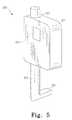
- FIG. 5is a perspective view of an exemplary communication device in accordance with the present teachings.
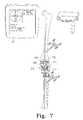
- FIGS. 6-9are fragmentary perspective views illustrating various steps of an exemplary tensor device being used in a surgical navigation knee procedure in accordance with the present teachings
- FIG. 11is a perspective view of an exemplary spinal distractor device in accordance with the present teachings.
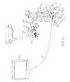
- FIG. 12is a perspective view of the exemplary spinal distractor of FIG. 11 being used to distract a pair of vertebral bodies in a surgical navigation spinal procedure;
- FIG. 13is a perspective view of the exemplary spinal distractor of FIG. 11 being used to distract a pair of vertebral bodies by way of pedicle screws attached thereto in a surgical navigation spinal procedure;
- FIG. 14is a perspective view of another exemplary spinal distractor device in accordance with the present teachings.
- FIG. 1shows a perspective view of an operating room with surgical navigation system 20 .
- Surgeon 21is aided by the surgical navigation system in performing knee arthroplasty, also known as knee replacement surgery, on patient 22 shown lying on operating table 24 .
- Surgical navigation system 20has a tracking system that locates arrays and tracks them in real-time.
- the surgical navigation systemincludes optical locator 23 , which has two CCD (charge couple device) cameras 25 that detect the positions of the arrays in space by using triangulation methods.
- the relative location of the tracked arrays, including the patient's anatomy,can then be shown on a computer display (such as computer display 27 for instance) to assist the surgeon during the surgical procedure.
- a computer displaysuch as computer display 27 for instance
- the arrays that are typically usedinclude probe arrays, instrument arrays, reference arrays, and calibrator arrays.
- the operating roomincludes an imaging system such as C-arm fluoroscope 26 with fluoroscope display image 28 to show a real-time image of the patient's knee on monitor 30 .
- Surgeon 21uses surgical probe 32 to reference a point on the patient's knee, and reference arrays 34 , 36 attached to the patient's femur and tibia to provide known anatomic reference points so the surgical navigation system can compensate for leg movement.
- the relative location of probe array 32 to the patient's tibiais then shown as reference numeral 40 on computer display image 38 of computer monitor 42 .
- the operating roomalso includes instrument cart 45 having tray 44 for holding a variety of surgical instruments and arrays 46 .
- Instrument cart 45 and C-arm 26are typically draped in sterile covers 48 a , 48 b to eliminate contamination risks within the sterile field.
- the surgeryis performed within a sterile field, adhering to the principles of asepsis by all scrubbed persons in the operating room.
- Patient 22 , surgeon 21 and assisting clinician 50are prepared for the sterile field through appropriate scrubbing and clothing.
- the sterile fieldwill typically extend from operating table 24 upward in the operating room.
- both computer display image 38 and fluoroscope display image 28are located outside of the sterile field.
- a representation of the patient's anatomycan be acquired with an imaging system, a virtual image, a morphed image, or a combination of imaging techniques.
- the imaging systemcan be any system capable of producing images that represent the patient s anatomy such as a fluoroscope producing x-ray two-dimensional images, computer tomography (CT) producing a three-dimensional image, magnetic resonance imaging (MRI) producing a three-dimensional image, ultrasound imaging producing a two-dimensional image, and the like.
- CTcomputer tomography
- MRImagnetic resonance imaging
- ultrasound imagingproducing a two-dimensional image
- a virtual image of the patient's anatomycan be created by defining anatomical points with surgical navigation system 20 or by applying a statistical anatomical model.
- a morphed image of the patient's anatomycan be created by combining an image of the patient's anatomy with a data set, such as a virtual image of the patient's anatomy.
- Some imaging systemssuch as C-arm fluoroscope 26 , can require calibration.
- the C-armcan be calibrated with a calibration grid that enables determination of fluoroscope projection parameters for different orientations of the C-arm to reduce distortion.
- a registration phantomcan also be used with a C-arm to coordinate images with the surgical navigation application program and improve scaling through the registration of the C-arm with the surgical navigation system.
- FIG. 2is a block diagram of an exemplary surgical navigation system embodiment in accordance with the present teachings, such as an AcumenTM Surgical Navigation System available from EBI, L.P., Parsipaimy, N.J. USA, a Biomet Company.
- the surgical navigation system 110comprises computer 112 , input device 114 , output device 116 , removable storage device 118 , tracking system 120 , arrays 122 , and patient anatomical data 124 , as further described in the brochure AcumenTM Surgical Navigation System, Understanding Surgical Navigation (2003), available from EBI, L.P.
- the AcumenTM Surgical Navigation Systemcan operate in a variety of imaging modes such as a fluoroscopy mode creating a two-dimensional x-ray image, a computer-tomography (CT) mode creating a three-dimensional image, and an imageless mode creating a virtual image or planes and axes by defining anatomical points of the patient's anatomy. In the imageless mode, a separate imaging device such as a C-arm is not required, thereby simplifying set-up.
- the AcumenTM Surgical Navigation Systemcan run a variety of orthopedic applications, including applications for knee arthroplasty, hip arthroplasty, spine surgery, and trauma surgery, as further described in the brochure “AcumenTM Surgical Navigation System, Surgical Navigation Applications” (2003) available from EBI, L.P.
- Computer 112can be any computer capable of properly operating surgical navigation devices and software, such as a computer similar to a commercially available personal computer that comprises a processor 126 , working memory 128 , core surgical navigation utilities 130 , an application program 132 , stored images 134 , and application data 136 .
- Processor 126is a processor of sufficient power for computer 112 to perform desired functions, such as one or more microprocessors.
- Working memory 128is memory sufficient for computer 112 to perform desired functions such as solid-state memory, random-access memory, and the like.
- Core surgical navigation utilities 130are the basic operating programs, and include image registration, image acquisition, location algorithms, orientation algorithms, virtual keypad, diagnostics, and the like.
- Application program 132can be any program configured for a specific surgical navigation purpose, such as orthopedic application programs for unicondylar knee (“uni-kee”), total knee, hip, spine, trauma, intramedullary (“IM”) nail, and external fixator.
- Stored images 134are those recorded during image acquisition using any of the imaging systems previously discussed.
- Application data 136is data that is generated or used by application program 132 , such as implant geometries, instrument geometries, surgical defaults, patient landmarks, and the like.
- Application data 136can be pre-loaded in the software or input by the user during a surgical navigation procedure.
- Output device 116can be any device capable of creating an output useful for surgery, such as a visual output and an auditory output.
- the visual output devicecan be any device capable of creating a visual output useful for surgery, such as a two-dimensional image, a three-dimensional image, a holographic image, and the like.
- the visual output devicecan be a monitor for producing two and three-dimensional images, a projector for producing two and three-dimensional images, and indicator lights.
- the auditory outputcan be any device capable of creating an auditory output used for surgery, such as a speaker that can be used to provide a voice or tone output.
- Removable storage device 118can be any device having a removable storage media that would allow downloading data such as application data 136 and patient anatomical data 124 .
- the removable storage devicecan be a read-write compact disc (CD) drive, a read-write digital video disc (DVD) drive, a flash solid-state memory port, a removable hard drive, a floppy disc drive, and the like.
- Tracking system 120can be any system that can determine the three-dimensional location of devices carrying or incorporating markers that serve as tracking indicia.
- An active tracking systemhas a collection of infrared light emitting diode (ILEDs) illuminators that surround the position sensor lenses to flood a measurement field of view with infrared light.
- ILEDsinfrared light emitting diode
- a passive systemincorporates retro-reflective markers that reflect infrared light back to the position sensor, and the system triangulates the real-time position (x, y, and z location) and orientation (rotation around x, y, and z axes) of an array 122 and reports the result to the computer system with an accuracy of about 0.35 mm Root Mean Squared (RMS).
- RMSRoot Mean Squared
- An example of passive tracking systemis a Polaris® Passive System and an example of a marker is the NDI Passive SpheresTM both available from Northern Digital Inc. Ontario, Canada.
- a hybrid tracking systemcan detect active and active wireless markers in addition to passive markers. Active marker based instruments enable automatic tool identification, program control of visible LEDs, and input via tool buttons.
- An example of a hybrid tracking systemis the Polaris® Hybrid System available from Northern Digital Inc.
- a markercan be a passive IR reflector, an active IR emitter, an electromagnetic marker, and an optical marker used with an optical camera.
- implants and instrumentsmay also be tracked by electromagnetic tracking systems. These systems locate and track devices and produce a real-time, three-dimensional video display of the surgical procedure. This is accomplished by using electromagnetic field transmitters that generate a local magnetic field around the patient's anatomy.
- the localization systemincludes magnetic sensors that identify the position of tracked instruments as they move relative to the patient's anatomy.
- electromagnetic systemsare also adapted for in vivo use, and are also integrable, for instance, with ultrasound and CT imaging processes for performing interventional procedures by incorporating miniaturized tracking sensors into surgical instruments. By processing transmitted signals generated by the tracking sensors, the system is able to determine the position of the surgical instruments in space, as well as superimpose their relative positions onto pre-operatively captured CT images of the patient.
- Arrays 122can be probe arrays, instrument arrays, reference arrays, calibrator arrays, and the like. Arrays 122 can have any number of markers, but typically have three or more markers to define real-time position (x, y, and z location) and orientation (rotation around x, y, and z axes). As will be explained in greater detail below, an array comprises a body and markers. The body comprises an area for spatial separation of markers. In some embodiments, there are at least two arms and some embodiments can have three arms, four arms, or more. The arms are typically arranged asymmetrically to facilitate specific array and marker identification by the tracking system. In other embodiments, such as a calibrator array, the body provides sufficient area for spatial separation of markers without the need for arms.
- Arrayscan be disposable or non-disposable.
- Disposable arraysare typically manufactured from plastic and include installed markers.
- Non-disposable arraysare manufactured from a material that can be sterilized, such as aluminum, stainless steel, and the like. The markers are removable, so they can be removed before sterilization.
- Planning and collecting patient anatomical data 124is a process by which a clinician inputs into the surgical navigation system actual or approximate anatomical data.
- Anatomical datacan be obtained through techniques such as anatomic painting, bone morphing, CT data input, and other inputs, such as ultrasound and fluoroscope and other imaging systems.
- FIGS. 3 and 4illustrate an exemplary knee distraction device or tensor 300 for use with surgical navigation system 20 .
- Tensor 300includes a first bone engaging member 302 and a pair of second bone engaging members 304 a , 304 b , which are vertically adjustable relative to one another and to member 302 .
- bone engaging members 304 a , 304 bare respectively coupled to outer shafts 314 a , 314 b , which are movable along vertical axis 315 .
- Outer shafts 314 a , 314 beach include an extension peg 319 a , 319 b that extends horizontally away from its front surface 325 a , 325 b , respectively, and is positioned adjacent to and substantially on top of ends 313 a , 313 b of pivot arm 313 .
- Pivot arm 313extends outwardly from shaft 311 and is configured to pivot upwardly or downwardly relative to central peg 303 much like a seesaw structure pivoting about a central fulcrum point.
- Rod 309is housed in tubular member 310 and is fixably attached to operating knob or dial 312 near its distal end 327 .
- Proximal end 328 of rod 309is housed inside of central bore 339 of shaft 311 and is configured to move upwardly relative to the shaft. More particularly, rod 309 may advance into central bore 339 of shaft 311 , as described in more detail below.
- Load cell 336is fixably coupled to rod 309 and includes an upper surface 329 to support spring 316 .
- Spring 316surrounds rod 309 and is positioned between upper surface 329 of load cell 336 and bottom surface 331 of the shaft 311 , to which it is keyed.
- Tensor 300further includes a removable and autoclavable transmitter 320 (best shown in FIG. 5 ), which detects and transmits the value of force applied to bone engaging members 304 a , 304 b at any give time to the computer of the navigation system.
- Transmitter 320includes a body 321 , attachment port 324 for connecting the transmitter to the tensor at one of attachment pegs 349 , and attachment arm 322 , which is configured to move relative to body 321 by way of internal bore 323 .
- Body 321houses the internal sensing circuitry of the transmitter which is configured to detect and measure distraction forces.
- transmitter 320further comprises a sensor, such as a transducer device that is configured to detect the value of force applied by the force-applying means of the tensor and transmit this force to the computer system.
- a sensorsuch as a transducer device that is configured to detect the value of force applied by the force-applying means of the tensor and transmit this force to the computer system.
- attachment arm 322has a sensing arm 326 that is sandwiched between the end 313 a of pivot arm 313 and extension peg 319 a .
- Sensing arm 326is configured with a pressure sensitive material or film, such as FlexiForce® Load/Force Sensors and System manufactured by Tekscan, Inc., 307 West First Street. South Boston, Mass.
- transmitter 320is able to detect the distraction force and translate it into a pressure reading to be transmitted to the computer system via a communication link.
- transmitter 320is an infrared transmitter device capable of establishing a communication link with the navigation system. Infrared transmission devices are known in the art and do not need to be discussed in further detail here.
- transmitter 320is also configured to measure and transmit the space between members 302 and 304 a , 304 b and/or the distance between the tibial plateau and the condyles during the distraction process. More particularly, as a downward force is exerted onto outer shaft 314 a and ultimately onto pivot arm 313 , the left side of the pivot arm pivots downwardly and correspondingly causes attachment arm 322 to displace downwardly relative to body 321 through the internal bore 323 . This displacement is measured by the transmitter and then transmitted to the navigation system.
- the tensoris also adapted to comprise a gap or joint space indicator 318 on one or both of the outer shafts 314 a , 314 b .
- indicator 318includes a visible indication screen (such as an LCD screen or other such display surface) which is located directly on the surface of the tensor and configured to display the distance between the tibial plateau and the condyles and/or the distance between the bone engaging members during the distraction process.
- rod 309may advance upwardly along vertical axis 315 and further into central bore 339 of shaft 311 .
- the extent to which rod 309 advances into central bore 339depends on the extent of the resistance bone engaging members 304 a , 304 b encounter from soft tissue or bone during the distraction process. If bone engaging members 304 a , 304 b are free to move upward without encountering significant resistance from either bone or soft tissue, rod 309 advances further into central bore 339 .
- load cell 336which is fixably attached to rod 309 , also moves upwardly along the vertical axis.
- Load cell 336exerts a compressive force on spring 316 and causes it to upwardly bias the bottom portion 331 of shaft 311 .
- spring 316may compress somewhat as it engages the bottom portion 331 of shaft 311 .
- the amount spring 316 compresseswill depend on the amount of resistance against upward movement provided by bone engaging members 304 a , 304 b during the distraction process.
- spring 316may not compress at all or may only slightly compress. However, once either one of bone engaging members 304 a , 304 b encounters significant resistance from soft tissue or bone, spring 316 will compress in response to this resistance. This resistance is received by the corresponding outer shaft ( 314 a , 314 b ) of the bone engaging member, which in turn forces the extension peg ( 319 a or 319 b ) to press against or come into contact with the corresponding end portion ( 313 a or 313 b ) of pivot arm 313 .
- load cell 336is a wired or wireless load cell capable of calculating the exerted force and transmitting this value to the navigation system. Load cells are known within the art and do not need to be discussed in further detail here.
- pivot arm 313is pivotably mounted to shaft 311 and thus moves upwardly along with shaft 311 . As this happens, the ends 313 a and 313 b of pivot arm exert upward forces on pegs 319 a and 319 b , respectively.
- the amount of resistance the ends encounter by pegs 319 a and 319 b at any given timedepends upon the individual force encountered by bone engaging members 304 a and 304 b from the respective ligaments or bones being distracted.
- the bone engaging members 304 a , 304 bfirst begin displacing away from member 302 , they will likely not be touching their respective condyles and therefore will likely encounter little resistance, such that arm 311 will not significantly pivot about peg 319 a as shaft 311 moves upwardly.
- tensor 300is placed between tibia 500 and femur 502 of a knee with the leg in 5-10 degrees of flexion. More particularly, the bottom surface 306 of first bone engaging member 302 rests on the tibial plateau of the tibia while the upper surfaces 308 a , 308 b of the femoral condyle-engaging members 304 a , 304 b engage the respective condyles of the femur.
- Tensionis applied with the leg in 5-10 degrees of flexion to ensure that tension is applied to the collaterals and not the posterior capsule.
- the surgeon 21adjusts the tensor 300 to apply an equal amount of force (e.g., 20-30 lbs.) to both collateral ligaments 504 (i.e., medial and lateral).
- Pivot arm 313is configured such that it automatically distributes the force load evenly between the condyles/collaterals.
- FIG. 6depicts surgeon 21 just finishing the application of increasing force to the medial collateral ligament, such that monitor 28 lists a force of 25 lbs. on each ligament.
- the monitorindicates that the knee suffers a vams deformity of 5 degrees and instructs the surgeon to “release” the MCL, or medial collateral ligament. Since the software indicates a varus angle, surgeon 21 must address the soft tissue accordingly by performing a soft tissue release. To perform this release, the tensor is removed from the leg.
- Releasing the MCLcan be accomplished by conventional means, typically involving cutting a part of the ligament to extend its length. After the MCL is released, the tensor is replaced and the upper leg alignment checked again. It should be understood and appreciated that the releasing of soft tissue is an iterative process and may be required more than once before completed. As such, the force of the tensor is once again adjusted to provide equal forces to both ligaments. As shown in FIG. 7 , monitor 28 indicates that the force exerted on the ligaments is the same and the varus deformity has been corrected. Once proper balance has been achieved, the extension gap is next captured using the computer s software.
- the surgeonmoves the patient's leg into 90 degree flexion and again performs soft tissue balancing.
- the tensorWith the knee positioned at 90 degrees, the tensor is positioned such that the tibia engaging-member is placed on the resected tibial plateau and the femoral engaging-members under the posterior condyles.
- the operating dial 312is turned until appropriate tension is achieved (e.g., 20-30 lbs.).
- the femoral rotation of the kneeis assessed by checking and comparing the values of the epicondylar axis, A/P axis, and Posterior condylar axis displayed by the software. Once proper balance has been achieved, the extension gap is once again captured using the computer's software.
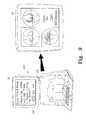
- computer system 600is utilized to establish femoral sizing and rotation.
- the softwarewill position the posterior and distal cuts and the rotation of the implant so that the flexion and extension gaps are appropriately balanced.
- the extension gapis 18.4 mm and the flexion gap 15.5 mm. If this information is appropriate, such that the gaps are deemed balanced, the surgeon will proceed to implant sizing by selecting the “yes” button 330 on monitor 28 . If the gaps are deemed not to be balanced, however, the surgeon can instead select the “no” button 335 on monitor 28 and repeat the balancing process as described above.
- the legcan be returned to extension and the tensor reinserted to apply an equal amount of force on the MCL and LCL.
- the location of the anterior femoral condyle cutsare chosen so that the extension and flexion gaps are balanced.
- the tensorhas been used to sufficiently balance the extension and flexion gaps such that when the implant is installed, it should remain stable as the knee is moved from extension to flexion.
- surgeon 21uses spatula probe 700 to place cutting block 705 along the femur 710 to perform a distal resection.
- computer monitor 28guides surgeon 21 as the block is positioned on the femur.
- surgeon 21can determine when cutting slot 715 (represented by line 720 on monitor 28 ) is aligned with the resection cutting plane 725 .
- markers 730 on spatula probe 700are tracked by cameras 735 of optical locator 740 , which are configured to determine the positions of the markers in space by using triangulation methods (see optical path represented by dashed lines 737 ).
- first and second bone engaging membersare respectively adapted to engage first and second vertebral bodies or discs within the spinal column.
- Spinal distractor (tensor) 800includes a pair of handles 802 , 804 that are configured to cause a pair of bone engaging distraction members 806 , 808 coupled thereto to move relative to one another substantially along distraction axis 810 during a spinal distraction process.
- handles 802 , 804 and bone engaging distraction members 806 , 808are pivotally coupled to each other in a scissors-like (or double scissors-like) configuration such that when the pair of handles are actuated (i.e., squeezed together along distraction axis 810 ), the distraction members are caused to correspondingly move apart from one another, thereby distracting the vertebral bodies between which the tips 812 , 814 of the distraction members are positioned.
- Spinal distractor 800also includes locking mechanism 816 that is provided to maintain a desired spacing of bone engaging distraction members 806 , 808 during the spinal distraction procedure.
- locking mechanism 816includes a threaded bolt 818 that is pivotally coupled to handle 804 and slidably passable therethrough.
- threaded bolt 818includes locking nut 820 , which is threadably coupled thereto and configured such that its rotation causes the length of bolt 818 positioned between handles 802 , 804 to shorten or lengthen as desired.
- the mechanical operation of such spinal distraction devicesis generally known within the bone distraction art and does not require further discussion herein (see for instance, U.S. Pat. Nos. 6,017,342, 6,712,825 and 7,081,118).
- conventional spinal distractorsoperate on a purely mechanical level. More particularly, the distractor is inserted between the spinal bodies and a force is applied to expand the bodies as needed. The amount of distraction (displacement) and the amount of force that is applied is not determined. However, it is important to not distract the spine too much or apply an unhealthy force to the spine, as it may cause additional injury or an undesired outcome. To minimize these problems, the present teachings provide a means to quantitatively measure both displacement and force during the distraction of two or more spinal members during a distraction procedure.
- spinal distractor 800is a navigated spinal distractor that can be utilized to measure displacement and/or force.
- transducers 824are placed on the distractor and are configured to communicate with a computer 826 that is placed within the operating room.
- bone engaging distraction members 806 , 808each include a transducer or load cell device, which is located on the outside portion of its tip 812 , 814 .
- These transducersare comprised of a pressure sensitive material or film, such as FlexiForceo Load/Force Sensors and System manufactured by Tekscan, Inc., 307 West First Street. South Boston, Mass. 02127-1309.
- Transducers 824are capable of determining the pressure encountered by either one of bone engaging distraction members 806 , 808 when they respectively contact a vertebral member (e.g., see reference numerals 830 , 832 in FIG. 12 ) or a hex shoulder of a pedicle screw that affixed to the spine (e.g., see reference numerals 834 , 836 in FIG. 13 ). More particularly, when either one of the bone engaging distraction members 806 , 808 come into contact with a vertebral body or associated hardware attached to such vertebral body (e.g., pedicle screw), that distraction member will encounter resistance to movement along distraction axis 810 .
- transducers 824contain a pressure sensitive material
- the distraction forceis detectable and translatable into a pressure reading that is transmittable to computer 826 via a communication link.
- the pressure readingis transmitted by the transducers via an infrared transmitter device capable of establishing a communication link with the navigation system. Infrared transmission devices are known in the art and do not need to be discussed in further detail here.
- the communication linkis established with the navigation system through a hard-wired connection 828 . Whatever means is used to transmit the pressure reading to computer 826 , the computer is then configured to record, process and display to the user 829 this force information so that it can be further considered and analyzed as needed.
- trackable array 838is placed on distractor 800 .
- the systemis able to measure the amount of displacement, including rotation and orientation, of the distractor and therefore the displacing members (e.g., vertebral bodies, pedicle screws etc., as referenced above).
- distractor 900includes a pair of bone engaging distraction members 902 and a distraction mechanism 904 for applying and controlling the amount of distraction, if any, desired by the surgeon.
- the distractor members 902can be placed over pins 905 drilled into vertebral bodies 906 , 908 and then adjusted horizontally with respect to one another to move or distract the vertebral bodies as desired.
- Spinal distractor 900also includes locking mechanism 911 that is provided to maintain a desired spacing of distraction members 902 , during the spinal distraction procedure.
- locking mechanism 911includes a threaded bolt 913 that is pivotally coupled to distraction arm 917 and slidably passable therethrough.
- threaded bolt 913includes locking nut 915 , which is threadably and rotatably coupled thereto and configured such that its rotation causes the length of bolt 913 positioned between distraction arms 917 , 919 to shorten or lengthen as desired.
- the mechanical operation of such spinal distraction deviceis generally known within the distraction art and can be found for instance, in U.S. Patent Application Publication No. 20060085077, the disclosure of which is incorporated in its entirety by this reference.
- transducers 910are positioned at the base of pils 905 and configured to communicate with a computer 912 by either a hard-wired 914 or wireless connection. More particularly, pins 905 each include a transducer or load cell device, which is located on the outside portion of its base. These transducers are comprised of a pressure sensitive material or film, such as FlexiForce® Load/Force Sensors and System manufactured by Tekscan, Inc., 307 West First Street. South Boston, Mass. 02127-1309. Transducers 910 are capable of determining the pressure encountered by either one of bone engaging distraction members 902 when they respectively contact the pins that are drilled into vertebral bodies 906 , 908 .
- transducers 910contain a pressure sensitive material, the distraction force is detectable and translatable into a pressure reading that is transmittable to computer 912 via a communication link.
- the pressure readingis transmitted by the transducers via an infrared transmitter device capable of establishing a communication link with the navigation system. Infrared transmission devices are known in the art and do not need to be discussed in further detail here.
- the communication linkis established with the navigation system through a hard-wired connection 914 .
- the computeris then configured to record, process and display to a user this force information so that it can be further considered and analyzed as needed. While this exemplary embodiment illustrates transducers 910 on both pins 905 , it should be understood and appreciated herein that the transducers could alternatively be placed on both ends of distraction members 902 of the distractor itself. As such, the present teachings are not intended to be limited herein.
- the amount of displacement between the vertebral bodies 906 , 908may also be measured.
- trackable array 916is placed on distractor 900 .
- the systemis able to measure the amount of displacement, including rotations and orientations, of the distractor and therefore the displacing members (e.g., vertebral bodies, etc., as referenced above).
Landscapes
- Health & Medical Sciences (AREA)
- Surgery (AREA)
- Life Sciences & Earth Sciences (AREA)
- Engineering & Computer Science (AREA)
- Heart & Thoracic Surgery (AREA)
- Biomedical Technology (AREA)
- Nuclear Medicine, Radiotherapy & Molecular Imaging (AREA)
- Medical Informatics (AREA)
- Molecular Biology (AREA)
- Animal Behavior & Ethology (AREA)
- General Health & Medical Sciences (AREA)
- Public Health (AREA)
- Veterinary Medicine (AREA)
- Pathology (AREA)
- Oral & Maxillofacial Surgery (AREA)
- Robotics (AREA)
- Surgical Instruments (AREA)
Abstract
Description
Claims (23)
Priority Applications (1)
| Application Number | Priority Date | Filing Date | Title |
|---|---|---|---|
| US11/681,227US8323290B2 (en) | 2006-03-03 | 2007-03-02 | Tensor for use in surgical navigation |
Applications Claiming Priority (2)
| Application Number | Priority Date | Filing Date | Title |
|---|---|---|---|
| US77870906P | 2006-03-03 | 2006-03-03 | |
| US11/681,227US8323290B2 (en) | 2006-03-03 | 2007-03-02 | Tensor for use in surgical navigation |
Publications (2)
| Publication Number | Publication Date |
|---|---|
| US20070244488A1 US20070244488A1 (en) | 2007-10-18 |
| US8323290B2true US8323290B2 (en) | 2012-12-04 |
Family
ID=38605782
Family Applications (1)
| Application Number | Title | Priority Date | Filing Date |
|---|---|---|---|
| US11/681,227Active2030-08-24US8323290B2 (en) | 2006-03-03 | 2007-03-02 | Tensor for use in surgical navigation |
Country Status (1)
| Country | Link |
|---|---|
| US (1) | US8323290B2 (en) |
Cited By (58)
| Publication number | Priority date | Publication date | Assignee | Title |
|---|---|---|---|---|
| US20120238911A1 (en)* | 2008-06-27 | 2012-09-20 | Ryan Chessar | Knee ligament balancer |
| US20150230804A1 (en)* | 2008-10-30 | 2015-08-20 | Synvasive Technology, Inc. | Force sensing distal femoral alignment system and method of use |
| US9498255B2 (en) | 2013-12-31 | 2016-11-22 | Blackstone Medical, Inc. | Translational pedicle screw systems |
| US20170312033A1 (en)* | 2016-04-27 | 2017-11-02 | Metal Industries Research&Development Centre | Surgery navigation system |
| US20180177612A1 (en)* | 2016-12-22 | 2018-06-28 | Orthosensor Inc. | Surgical Apparatus to Support Installation of a Prosthetic Component With Reduced Alignment Error |
| US10016220B2 (en) | 2011-11-01 | 2018-07-10 | Nuvasive Specialized Orthopedics, Inc. | Adjustable magnetic devices and methods of using same |
| US10039661B2 (en) | 2006-10-20 | 2018-08-07 | Nuvasive Specialized Orthopedics, Inc. | Adjustable implant and method of use |
| US10136952B2 (en) | 2016-06-16 | 2018-11-27 | Zimmer, Inc. | Soft tissue balancing in articular surgery |
| US10238427B2 (en) | 2015-02-19 | 2019-03-26 | Nuvasive Specialized Orthopedics, Inc. | Systems and methods for vertebral adjustment |
| US10271885B2 (en) | 2014-12-26 | 2019-04-30 | Nuvasive Specialized Orthopedics, Inc. | Systems and methods for distraction |
| US10349995B2 (en) | 2007-10-30 | 2019-07-16 | Nuvasive Specialized Orthopedics, Inc. | Skeletal manipulation method |
| US10405891B2 (en) | 2010-08-09 | 2019-09-10 | Nuvasive Specialized Orthopedics, Inc. | Maintenance feature in magnetic implant |
| US10478232B2 (en) | 2009-04-29 | 2019-11-19 | Nuvasive Specialized Orthopedics, Inc. | Interspinous process device and method |
| US10485554B2 (en) | 2008-10-30 | 2019-11-26 | Synvasive Technology, Inc. | System for positioning a cutting guide in knee surgery |
| US10517643B2 (en) | 2009-02-23 | 2019-12-31 | Nuvasive Specialized Orthopedics, Inc. | Non-invasive adjustable distraction system |
| US10617453B2 (en) | 2015-10-16 | 2020-04-14 | Nuvasive Specialized Orthopedics, Inc. | Adjustable devices for treating arthritis of the knee |
| US10646262B2 (en) | 2011-02-14 | 2020-05-12 | Nuvasive Specialized Orthopedics, Inc. | System and method for altering rotational alignment of bone sections |
| US10660675B2 (en) | 2010-06-30 | 2020-05-26 | Nuvasive Specialized Orthopedics, Inc. | External adjustment device for distraction device |
| US10729470B2 (en) | 2008-11-10 | 2020-08-04 | Nuvasive Specialized Orthopedics, Inc. | External adjustment device for distraction device |
| US10743794B2 (en) | 2011-10-04 | 2020-08-18 | Nuvasive Specialized Orthopedics, Inc. | Devices and methods for non-invasive implant length sensing |
| US10751094B2 (en) | 2013-10-10 | 2020-08-25 | Nuvasive Specialized Orthopedics, Inc. | Adjustable spinal implant |
| US10835290B2 (en) | 2015-12-10 | 2020-11-17 | Nuvasive Specialized Orthopedics, Inc. | External adjustment device for distraction device |
| US10918425B2 (en) | 2016-01-28 | 2021-02-16 | Nuvasive Specialized Orthopedics, Inc. | System and methods for bone transport |
| US11185425B2 (en) | 2016-12-22 | 2021-11-30 | Orthosensor Inc. | Surgical tensor configured to distribute loading through at least two pivot points |
| US11191579B2 (en) | 2012-10-29 | 2021-12-07 | Nuvasive Specialized Orthopedics, Inc. | Adjustable devices for treating arthritis of the knee |
| US11202707B2 (en) | 2008-03-25 | 2021-12-21 | Nuvasive Specialized Orthopedics, Inc. | Adjustable implant system |
| US11207110B2 (en) | 2009-09-04 | 2021-12-28 | Nuvasive Specialized Orthopedics, Inc. | Bone growth device and method |
| US11229489B2 (en) | 2016-06-16 | 2022-01-25 | Zimmer, Inc. | Soft tissue balancing in articular surgery |
| US11246694B2 (en) | 2014-04-28 | 2022-02-15 | Nuvasive Specialized Orthopedics, Inc. | System for informational magnetic feedback in adjustable implants |
| US11266512B2 (en) | 2016-12-22 | 2022-03-08 | Orthosensor Inc. | Surgical apparatus to support installation of a prosthetic component and method therefore |
| US11284873B2 (en) | 2016-12-22 | 2022-03-29 | Orthosensor Inc. | Surgical tensor where each distraction mechanism is supported and aligned by at least two guide shafts |
| US11291437B2 (en) | 2016-12-22 | 2022-04-05 | Orthosensor Inc. | Tilting surgical tensor to support at least one bone cut |
| US11317954B2 (en) | 2017-07-28 | 2022-05-03 | Wright Medical Technology, Inc. | Joint osteotomy system and method |
| USRE49061E1 (en) | 2012-10-18 | 2022-05-10 | Nuvasive Specialized Orthopedics, Inc. | Intramedullary implants for replacing lost bone |
| US11357547B2 (en) | 2014-10-23 | 2022-06-14 | Nuvasive Specialized Orthopedics Inc. | Remotely adjustable interactive bone reshaping implant |
| US11357644B2 (en) | 2011-10-24 | 2022-06-14 | Synvasive Technology, Inc. | Knee balancing devices, systems and methods |
| US11357549B2 (en) | 2004-07-02 | 2022-06-14 | Nuvasive Specialized Orthopedics, Inc. | Expandable rod system to treat scoliosis and method of using the same |
| US11432811B2 (en) | 2019-05-09 | 2022-09-06 | Mako Surgical Corp. | Joint gap balancing lever and methods of use thereof |
| US11577097B2 (en) | 2019-02-07 | 2023-02-14 | Nuvasive Specialized Orthopedics, Inc. | Ultrasonic communication in medical devices |
| US11589901B2 (en) | 2019-02-08 | 2023-02-28 | Nuvasive Specialized Orthopedics, Inc. | External adjustment device |
| US20230072295A1 (en)* | 2020-02-11 | 2023-03-09 | Smith & Nephew, Inc. | A joint tensioning device and methods of use thereof |
| US11666318B2 (en) | 2019-08-30 | 2023-06-06 | Mako Surgical Corp. | Distraction device with disposable force sensor pod |
| US11696836B2 (en) | 2013-08-09 | 2023-07-11 | Nuvasive, Inc. | Lordotic expandable interbody implant |
| USD995790S1 (en) | 2020-03-30 | 2023-08-15 | Depuy Ireland Unlimited Company | Robotic surgical tool |
| US11737787B1 (en) | 2021-05-27 | 2023-08-29 | Nuvasive, Inc. | Bone elongating devices and methods of use |
| US11766252B2 (en) | 2013-07-31 | 2023-09-26 | Nuvasive Specialized Orthopedics, Inc. | Noninvasively adjustable suture anchors |
| US11801187B2 (en) | 2016-02-10 | 2023-10-31 | Nuvasive Specialized Orthopedics, Inc. | Systems and methods for controlling multiple surgical variables |
| US11806054B2 (en) | 2021-02-23 | 2023-11-07 | Nuvasive Specialized Orthopedics, Inc. | Adjustable implant, system and methods |
| US11839410B2 (en) | 2012-06-15 | 2023-12-12 | Nuvasive Inc. | Magnetic implants with improved anatomical compatibility |
| US11857226B2 (en) | 2013-03-08 | 2024-01-02 | Nuvasive Specialized Orthopedics | Systems and methods for ultrasonic detection of device distraction |
| US11925389B2 (en) | 2008-10-13 | 2024-03-12 | Nuvasive Specialized Orthopedics, Inc. | Spinal distraction system |
| US12004816B2 (en) | 2020-03-30 | 2024-06-11 | Depuy Ireland Unlimited Company | Robotic surgical apparatus with positioning guide |
| US12023073B2 (en) | 2021-08-03 | 2024-07-02 | Nuvasive Specialized Orthopedics, Inc. | Adjustable implant |
| US12042944B2 (en) | 2020-03-30 | 2024-07-23 | Depuy Ireland Unlimited Company | Robotic surgical system with graphical user interface |
| US12064358B2 (en) | 2019-09-24 | 2024-08-20 | Mako Surgical Corp. | System and method for ligament balancing using robotically held device |
| US12201534B2 (en) | 2020-01-29 | 2025-01-21 | Howmedica Osteonics Corp. | Load sensor balancer instruments |
| US12213708B2 (en) | 2020-09-08 | 2025-02-04 | Nuvasive Specialized Orthopedics, Inc. | Remote control module for adjustable implants |
| US12324752B2 (en) | 2012-03-31 | 2025-06-10 | Depuy Ireland Unlimited Company | Orthopaedic surgical system for determining joint forces of a patient's knee joint |
Families Citing this family (88)
| Publication number | Priority date | Publication date | Assignee | Title |
|---|---|---|---|---|
| GB0107708D0 (en) | 2001-03-28 | 2001-05-16 | Imp College Innovations Ltd | Bone fixated,articulated joint load control device |
| US7559931B2 (en) | 2003-06-09 | 2009-07-14 | OrthAlign, Inc. | Surgical orientation system and method |
| US8328853B2 (en)* | 2006-04-03 | 2012-12-11 | Ib Medical, Llc | Static compression device |
| US7728868B2 (en) | 2006-08-02 | 2010-06-01 | Inneroptic Technology, Inc. | System and method of providing real-time dynamic imagery of a medical procedure site using multiple modalities |
| US7655041B2 (en) | 2007-05-01 | 2010-02-02 | Moximed, Inc. | Extra-articular implantable mechanical energy absorbing systems and implantation method |
| US10022154B2 (en)* | 2007-05-01 | 2018-07-17 | Moximed, Inc. | Femoral and tibial base components |
| US20100137996A1 (en) | 2007-05-01 | 2010-06-03 | Moximed, Inc. | Femoral and tibial base components |
| US8123805B2 (en) | 2007-05-01 | 2012-02-28 | Moximed, Inc. | Adjustable absorber designs for implantable device |
| US20110245928A1 (en) | 2010-04-06 | 2011-10-06 | Moximed, Inc. | Femoral and Tibial Bases |
| US8709090B2 (en) | 2007-05-01 | 2014-04-29 | Moximed, Inc. | Adjustable absorber designs for implantable device |
| US9907645B2 (en) | 2007-05-01 | 2018-03-06 | Moximed, Inc. | Adjustable absorber designs for implantable device |
| US20080275567A1 (en) | 2007-05-01 | 2008-11-06 | Exploramed Nc4, Inc. | Extra-Articular Implantable Mechanical Energy Absorbing Systems |
| US8894714B2 (en) | 2007-05-01 | 2014-11-25 | Moximed, Inc. | Unlinked implantable knee unloading device |
| US8409281B2 (en)* | 2007-05-01 | 2013-04-02 | Moximed, Inc. | Adjustable absorber designs for implantable device |
| US8425616B2 (en)* | 2007-07-09 | 2013-04-23 | Moximed, Inc. | Surgical implantation method and devices for an extra-articular mechanical energy absorbing apparatus |
| US7632310B2 (en)* | 2007-07-09 | 2009-12-15 | Moximed, Inc. | Surgical implantation method and devices for an extra-articular mechanical energy absorbing apparatus |
| US7846211B2 (en)* | 2007-07-09 | 2010-12-07 | Moximed, Inc. | Surgical implantation method and devices for an extra-articular mechanical energy absorbing apparatus |
| US20090018665A1 (en)* | 2007-07-09 | 2009-01-15 | Exploramed Nc4, Inc. | Surgical implantation method and devices for an extra-articular mechanical energy absorbing apparatus |
| WO2009094646A2 (en) | 2008-01-24 | 2009-07-30 | The University Of North Carolina At Chapel Hill | Methods, systems, and computer readable media for image guided ablation |
| US8340379B2 (en) | 2008-03-07 | 2012-12-25 | Inneroptic Technology, Inc. | Systems and methods for displaying guidance data based on updated deformable imaging data |
| AU2009273863B2 (en) | 2008-07-24 | 2014-12-18 | OrthAlign, Inc. | Systems and methods for joint replacement |
| US8252001B2 (en)* | 2008-08-28 | 2012-08-28 | Q-Spine Llc | Apparatus and methods for inter-operative verification of appropriate spinal prosthesis size and placement |
| AU2009291743B2 (en) | 2008-09-10 | 2015-02-05 | Orthalign, Inc | Hip surgery systems and methods |
| US20100094303A1 (en)* | 2008-10-13 | 2010-04-15 | Arvin Chang | Spinal distraction system |
| US11464578B2 (en) | 2009-02-17 | 2022-10-11 | Inneroptic Technology, Inc. | Systems, methods, apparatuses, and computer-readable media for image management in image-guided medical procedures |
| US8690776B2 (en) | 2009-02-17 | 2014-04-08 | Inneroptic Technology, Inc. | Systems, methods, apparatuses, and computer-readable media for image guided surgery |
| US8554307B2 (en) | 2010-04-12 | 2013-10-08 | Inneroptic Technology, Inc. | Image annotation in image-guided medical procedures |
| US8641621B2 (en) | 2009-02-17 | 2014-02-04 | Inneroptic Technology, Inc. | Systems, methods, apparatuses, and computer-readable media for image management in image-guided medical procedures |
| US8721568B2 (en) | 2009-03-31 | 2014-05-13 | Depuy (Ireland) | Method for performing an orthopaedic surgical procedure |
| US8551023B2 (en)* | 2009-03-31 | 2013-10-08 | Depuy (Ireland) | Device and method for determining force of a knee joint |
| US8556830B2 (en)* | 2009-03-31 | 2013-10-15 | Depuy | Device and method for displaying joint force data |
| US8597210B2 (en)* | 2009-03-31 | 2013-12-03 | Depuy (Ireland) | System and method for displaying joint force data |
| US8740817B2 (en)* | 2009-03-31 | 2014-06-03 | Depuy (Ireland) | Device and method for determining forces of a patient's joint |
| US9655628B2 (en) | 2009-05-06 | 2017-05-23 | Blue Ortho | Reduced invasivity fixation system for trackers in computer assisted surgery |
| EP2429408A1 (en)* | 2009-05-14 | 2012-03-21 | Blue Ortho | Device and method of automatic calibration of a tensor in arthroplasty procedures |
| ES2545398T3 (en)* | 2009-06-30 | 2015-09-10 | Blue Ortho | Adjustable guide for computer-assisted orthopedic surgery |
| US10869771B2 (en) | 2009-07-24 | 2020-12-22 | OrthAlign, Inc. | Systems and methods for joint replacement |
| US9861408B2 (en) | 2009-08-27 | 2018-01-09 | The Foundry, Llc | Method and apparatus for treating canine cruciate ligament disease |
| US9668868B2 (en) | 2009-08-27 | 2017-06-06 | Cotera, Inc. | Apparatus and methods for treatment of patellofemoral conditions |
| US9278004B2 (en) | 2009-08-27 | 2016-03-08 | Cotera, Inc. | Method and apparatus for altering biomechanics of the articular joints |
| US10349980B2 (en) | 2009-08-27 | 2019-07-16 | The Foundry, Llc | Method and apparatus for altering biomechanics of the shoulder |
| CA2771332C (en) | 2009-08-27 | 2020-11-10 | Cotera, Inc. | Method and apparatus for force redistribution in articular joints |
| US8523948B2 (en) | 2009-10-20 | 2013-09-03 | Moximed, Inc. | Extra-articular implantable mechanical energy absorbing assemblies having a tension member, and methods |
| US8679178B2 (en)* | 2009-10-20 | 2014-03-25 | Moximed, Inc. | Extra-articular implantable mechanical energy absorbing assemblies having two deflecting members and compliance member |
| US9282947B2 (en) | 2009-12-01 | 2016-03-15 | Inneroptic Technology, Inc. | Imager focusing based on intraoperative data |
| GB2479899A (en)* | 2010-04-28 | 2011-11-02 | Biomet Uk Ltd | Alignment tool for use in joint replacement |
| US9044270B2 (en) | 2011-03-29 | 2015-06-02 | Moximed, Inc. | Apparatus for controlling a load on a hip joint |
| GB201115411D0 (en) | 2011-09-07 | 2011-10-19 | Depuy Ireland | Surgical instrument |
| US11197797B2 (en)* | 2011-09-15 | 2021-12-14 | Sigma Instruments Holdings, Llc | System and method for treating soft tissue with force impulse and electrical stimulation |
| US8945133B2 (en)* | 2011-09-23 | 2015-02-03 | Orthosensor Inc | Spinal distraction tool for load and position measurement |
| CA2849895A1 (en)* | 2011-09-23 | 2013-03-28 | Martin Roche | System and method for vertebral load and location sensing |
| US9839374B2 (en)* | 2011-09-23 | 2017-12-12 | Orthosensor Inc. | System and method for vertebral load and location sensing |
| US8670816B2 (en) | 2012-01-30 | 2014-03-11 | Inneroptic Technology, Inc. | Multiple medical device guidance |
| US9381011B2 (en) | 2012-03-29 | 2016-07-05 | Depuy (Ireland) | Orthopedic surgical instrument for knee surgery |
| US9545459B2 (en) | 2012-03-31 | 2017-01-17 | Depuy Ireland Unlimited Company | Container for surgical instruments and system including same |
| US10070973B2 (en) | 2012-03-31 | 2018-09-11 | Depuy Ireland Unlimited Company | Orthopaedic sensor module and system for determining joint forces of a patient's knee joint |
| US10098761B2 (en) | 2012-03-31 | 2018-10-16 | DePuy Synthes Products, Inc. | System and method for validating an orthopaedic surgical plan |
| US8808328B2 (en)* | 2012-04-05 | 2014-08-19 | Tufts Medical Center, Inc. | Spring loaded mechanism for managing scoliosis |
| US9050197B2 (en) | 2012-07-23 | 2015-06-09 | Biomet Manufacturing, Llc | Knee sizing and balancing instrument |
| US9649160B2 (en) | 2012-08-14 | 2017-05-16 | OrthAlign, Inc. | Hip replacement navigation system and method |
| US9468466B1 (en) | 2012-08-24 | 2016-10-18 | Cotera, Inc. | Method and apparatus for altering biomechanics of the spine |
| USD696782S1 (en) | 2013-03-08 | 2013-12-31 | Stryker Corporation | Joint stabilizing instrument |
| US10314559B2 (en) | 2013-03-14 | 2019-06-11 | Inneroptic Technology, Inc. | Medical device guidance |
| US10452238B2 (en)* | 2013-03-15 | 2019-10-22 | Blue Belt Technologies, Inc. | Systems and methods for determining a position for placing of a joint prosthesis |
| CA2846729C (en)* | 2013-03-15 | 2022-10-04 | Synaptive Medical (Barbados) Inc. | Surgical pointer having constant pressure |
| US11246719B2 (en)* | 2013-08-13 | 2022-02-15 | Brainlab Ag | Medical registration apparatus and method for registering an axis |
| JP6666066B2 (en)* | 2014-09-30 | 2020-03-13 | 京セラ株式会社 | Knee replacement device and knee replacement device unit |
| US9901406B2 (en) | 2014-10-02 | 2018-02-27 | Inneroptic Technology, Inc. | Affected region display associated with a medical device |
| WO2016064632A1 (en)* | 2014-10-24 | 2016-04-28 | Covidien Lp | Sensorizing robotic surgical system access ports |
| US10188467B2 (en) | 2014-12-12 | 2019-01-29 | Inneroptic Technology, Inc. | Surgical guidance intersection display |
| US10363149B2 (en) | 2015-02-20 | 2019-07-30 | OrthAlign, Inc. | Hip replacement navigation system and method |
| US9949700B2 (en) | 2015-07-22 | 2018-04-24 | Inneroptic Technology, Inc. | Medical device approaches |
| US9675319B1 (en) | 2016-02-17 | 2017-06-13 | Inneroptic Technology, Inc. | Loupe display |
| WO2017185108A2 (en)* | 2016-04-28 | 2017-11-02 | Medfit Beratungs-Und Beteiligunges.M.B.H | Dynamic ligament balancing system (dlb) |
| US10278778B2 (en) | 2016-10-27 | 2019-05-07 | Inneroptic Technology, Inc. | Medical device navigation using a virtual 3D space |
| US10194995B2 (en)* | 2016-12-12 | 2019-02-05 | Medos International Sarl | Systems and methods for en bloc registration in navigated surgery |
| EP3585295B1 (en)* | 2017-02-27 | 2022-01-05 | Smith & Nephew, Inc. | Surgical navigation system support array |
| EP3590450B1 (en)* | 2017-03-03 | 2023-11-01 | Teijin Nakashima Medical Co., Ltd. | Osteotomy assistance kit |
| EP3595554A4 (en) | 2017-03-14 | 2021-01-06 | OrthAlign, Inc. | Hip replacement navigation systems and methods |
| CA3056495A1 (en)* | 2017-03-14 | 2018-09-20 | OrthAlign, Inc. | Soft tissue measurement & balancing systems and methods |
| US11259879B2 (en) | 2017-08-01 | 2022-03-01 | Inneroptic Technology, Inc. | Selective transparency to assist medical device navigation |
| US11484365B2 (en) | 2018-01-23 | 2022-11-01 | Inneroptic Technology, Inc. | Medical image guidance |
| US20190240045A1 (en) | 2018-02-02 | 2019-08-08 | Orthosoft, Inc. | Soft tissue balancing in robotic knee surgery |
| US12274631B2 (en) | 2018-02-02 | 2025-04-15 | Exactech, Inc. | Soft tissue balancing in robotic knee surgery |
| US20190240046A1 (en) | 2018-02-02 | 2019-08-08 | Orthosoft, Inc. | Range of motion evaluation in orthopedic surgery |
| US11877807B2 (en)* | 2020-07-10 | 2024-01-23 | Globus Medical, Inc | Instruments for navigated orthopedic surgeries |
| US20220183767A1 (en)* | 2020-12-15 | 2022-06-16 | Mako Surgical Corp. | Dynamic gap capture and flexion widget |
| WO2024187245A1 (en)* | 2023-03-16 | 2024-09-19 | Viortec Pty Ltd | Surgical clamp |
Citations (79)
| Publication number | Priority date | Publication date | Assignee | Title |
|---|---|---|---|---|
| US4341220A (en) | 1979-04-13 | 1982-07-27 | Pfizer Inc. | Stereotactic surgery apparatus and method |
| US4360028A (en) | 1980-01-14 | 1982-11-23 | Barbier Jean Y | Cranial insertion of surgical needle utilizing computer-assisted tomography |
| US4501266A (en)* | 1983-03-04 | 1985-02-26 | Biomet, Inc. | Knee distraction device |
| US5213112A (en)* | 1992-01-29 | 1993-05-25 | Pfizer Hospital Products Group, Inc. | Tension meter for orthopedic surgery |
| US5309913A (en) | 1992-11-30 | 1994-05-10 | The Cleveland Clinic Foundation | Frameless stereotaxy system |
| US5517990A (en) | 1992-11-30 | 1996-05-21 | The Cleveland Clinic Foundation | Stereotaxy wand and tool guide |
| US5611353A (en)* | 1993-06-21 | 1997-03-18 | Osteonics Corp. | Method and apparatus for locating functional structures of the lower leg during knee surgery |
| US5628315A (en) | 1994-09-15 | 1997-05-13 | Brainlab Med. Computersysteme Gmbh | Device for detecting the position of radiation target points |
| US5669914A (en)* | 1996-02-16 | 1997-09-23 | Board Of Regents Of The University Of Colorado | Rotation alignment instrument |
| US5688282A (en)* | 1995-08-24 | 1997-11-18 | Benois & Girard & Cie | Distraction apparatus for a knee |
| US5732703A (en) | 1992-11-30 | 1998-03-31 | The Cleveland Clinic Foundation | Stereotaxy wand and tool guide |
| US5769861A (en) | 1995-09-28 | 1998-06-23 | Brainlab Med. Computersysteme Gmbh | Method and devices for localizing an instrument |
| US5911723A (en)* | 1996-05-28 | 1999-06-15 | Howmedice International Inc. | Surgical apparatus |
| US5967982A (en) | 1997-12-09 | 1999-10-19 | The Cleveland Clinic Foundation | Non-invasive spine and bone registration for frameless stereotaxy |
| US5980535A (en) | 1996-09-30 | 1999-11-09 | Picker International, Inc. | Apparatus for anatomical tracking |
| US5999837A (en) | 1997-09-26 | 1999-12-07 | Picker International, Inc. | Localizing and orienting probe for view devices |
| US6021343A (en) | 1997-11-20 | 2000-02-01 | Surgical Navigation Technologies | Image guided awl/tap/screwdriver |
| US6122541A (en) | 1995-05-04 | 2000-09-19 | Radionics, Inc. | Head band for frameless stereotactic registration |
| US6190395B1 (en) | 1999-04-22 | 2001-02-20 | Surgical Navigation Technologies, Inc. | Image guided universal instrument adapter and method for use with computer-assisted image guided surgery |
| US6226548B1 (en) | 1997-09-24 | 2001-05-01 | Surgical Navigation Technologies, Inc. | Percutaneous registration apparatus and method for use in computer-assisted surgical navigation |
| US6236875B1 (en)* | 1994-10-07 | 2001-05-22 | Surgical Navigation Technologies | Surgical navigation systems including reference and localization frames |
| US6340363B1 (en) | 1998-10-09 | 2002-01-22 | Surgical Navigation Technologies, Inc. | Image guided vertebral distractor and method for tracking the position of vertebrae |
| US6348058B1 (en) | 1997-12-12 | 2002-02-19 | Surgical Navigation Technologies, Inc. | Image guided spinal surgery guide, system, and method for use thereof |
| US6385475B1 (en)* | 1997-03-11 | 2002-05-07 | Philippe Cinquin | Process and device for the preoperative determination of the positioning data of endoprosthetic parts |
| US20020095081A1 (en) | 1995-09-28 | 2002-07-18 | Brainlab Med. Computersysteme Gmbh | Neuro-navigation system |
| US6434507B1 (en) | 1997-09-05 | 2002-08-13 | Surgical Navigation Technologies, Inc. | Medical instrument and method for use with computer-assisted image guided surgery |
| US6471706B1 (en) | 2000-04-18 | 2002-10-29 | Walter Lorenz Surgical, Inc. | Resorbable bone distractor and method |
| US20030069591A1 (en) | 2001-02-27 | 2003-04-10 | Carson Christopher Patrick | Computer assisted knee arthroplasty instrumentation, systems, and processes |
| US6697664B2 (en) | 1999-02-10 | 2004-02-24 | Ge Medical Systems Global Technology Company, Llc | Computer assisted targeting device for use in orthopaedic surgery |
| US6725080B2 (en) | 2000-03-01 | 2004-04-20 | Surgical Navigation Technologies, Inc. | Multiple cannula image guided tool for image guided procedures |
| US20040102785A1 (en) | 2002-11-27 | 2004-05-27 | Hodorek Robert A. | Method and apparatus for achieving correct limb alignment in unicondylar knee arthroplasty |
| US20040249314A1 (en)* | 2003-06-09 | 2004-12-09 | Salla Prathyusha K. | Tempero-spatial physiological signal detection method and apparatus |
| US20040267242A1 (en) | 2003-06-24 | 2004-12-30 | Grimm James E. | Detachable support arm for surgical navigation system reference array |
| US20050015005A1 (en) | 2003-04-28 | 2005-01-20 | Kockro Ralf Alfons | Computer enhanced surgical navigation imaging system (camera probe) |
| US20050020941A1 (en)* | 2003-07-24 | 2005-01-27 | Samih Tarabichi | Dynamic spacer for total knee arthroplasty |
| US20050021039A1 (en) | 2003-02-04 | 2005-01-27 | Howmedica Osteonics Corp. | Apparatus for aligning an instrument during a surgical procedure |
| US20050021037A1 (en) | 2003-05-29 | 2005-01-27 | Mccombs Daniel L. | Image-guided navigated precision reamers |
| US20050021031A1 (en) | 1999-10-20 | 2005-01-27 | Foley Kevin T. | Instruments and methods for stabilization of bony structures |
| US6856828B2 (en) | 2002-10-04 | 2005-02-15 | Orthosoft Inc. | CAS bone reference and less invasive installation method thereof |
| US20050038514A1 (en) | 1999-05-07 | 2005-02-17 | Helm Gregory A. | Method and system for fusing a spinal region |
| US20050038432A1 (en) | 2003-04-25 | 2005-02-17 | Shaolian Samuel M. | Articulating spinal fixation rod and system |
| US6859661B2 (en)* | 2001-01-25 | 2005-02-22 | Finsbury (Development) Limited | Surgical system for use in the course of a knee replacement operation |
| US20050049485A1 (en) | 2003-08-27 | 2005-03-03 | Harmon Kim R. | Multiple configuration array for a surgical navigation system |
| US20050070900A1 (en) | 2003-09-30 | 2005-03-31 | Depuy Acromed, Inc. | Vertebral fusion device and method for using same |
| US20050075632A1 (en) | 2003-10-03 | 2005-04-07 | Russell Thomas A. | Surgical positioners |
| US20050080334A1 (en) | 2003-10-08 | 2005-04-14 | Scimed Life Systems, Inc. | Method and system for determining the location of a medical probe using a reference transducer array |
| US6887247B1 (en) | 2002-04-17 | 2005-05-03 | Orthosoft Inc. | CAS drill guide and drill tracking system |
| US6887245B2 (en) | 2001-06-11 | 2005-05-03 | Ge Medical Systems Global Technology Company, Llc | Surgical drill for use with a computer assisted surgery system |
| US20050101966A1 (en) | 2000-11-06 | 2005-05-12 | Stephane Lavallee | System for determining the position of a knee prosthesis |
| US20050113846A1 (en) | 2001-02-27 | 2005-05-26 | Carson Christopher P. | Surgical navigation systems and processes for unicompartmental knee arthroplasty |
| US20050113659A1 (en) | 2003-11-26 | 2005-05-26 | Albert Pothier | Device for data input for surgical navigation system |
| US6899714B2 (en) | 2001-10-03 | 2005-05-31 | Vaughan Medical Technologies, Inc. | Vertebral stabilization assembly and method |
| US20050119783A1 (en) | 2002-05-03 | 2005-06-02 | Carnegie Mellon University | Methods and systems to control a cutting tool |
| US20050119661A1 (en) | 2001-11-14 | 2005-06-02 | Hodgson Antony J. | Methods and systems for intraoperative measurement of soft tissue constraints in computer aided total joint replacement surgery |
| US6923817B2 (en) | 2001-02-27 | 2005-08-02 | Smith & Nephew, Inc. | Total knee arthroplasty systems and processes |
| US20050177169A1 (en) | 2004-02-06 | 2005-08-11 | Synvasive Technology, Inc. | Dynamic knee balancer |
| US20050215888A1 (en) | 2004-03-05 | 2005-09-29 | Grimm James E | Universal support arm and tracking array |
| US20050234332A1 (en) | 2004-01-16 | 2005-10-20 | Murphy Stephen B | Method of computer-assisted ligament balancing and component placement in total knee arthroplasty |
| US20050234461A1 (en) | 2001-05-25 | 2005-10-20 | Burdulis Albert G Jr | Surgical tools facilitating increased accuracy, speed and simplicity in performing joint arthroplasty |
| US20050234465A1 (en) | 2004-03-31 | 2005-10-20 | Mccombs Daniel L | Guided saw with pins |
| US20050251065A1 (en) | 2004-04-27 | 2005-11-10 | Stefan Henning | Planning method and planning device for knee implants |
| US20050251148A1 (en) | 2002-11-05 | 2005-11-10 | Aesculap Ag & Co. Kg | Method and device for determining the position of a knee-joint endoprosthesis |
| US20050261680A1 (en)* | 2001-03-28 | 2005-11-24 | Imperial College Innovations Ltd. | Bone fixated, articulated joint load control device |
| US20050267353A1 (en) | 2004-02-04 | 2005-12-01 | Joel Marquart | Computer-assisted knee replacement apparatus and method |
| US20050267358A1 (en) | 2004-02-11 | 2005-12-01 | Gregor Tuma | Adjustable marker arrangement |
| US20050267354A1 (en) | 2003-02-04 | 2005-12-01 | Joel Marquart | System and method for providing computer assistance with spinal fixation procedures |
| US6980849B2 (en) | 2002-04-17 | 2005-12-27 | Ricardo Sasso | Instrumentation and method for performing image-guided spinal surgery using an anterior surgical approach |
| US20060009778A1 (en) | 2004-06-29 | 2006-01-12 | Keith Collins | Methods for treating defects and injuries of an intervertebral disc |
| US20060015031A1 (en)* | 2004-07-19 | 2006-01-19 | General Electric Company | System and method for tracking progress of insertion of a rod in a bone |
| US20060015018A1 (en) | 2003-02-04 | 2006-01-19 | Sebastien Jutras | CAS modular body reference and limb position measurement system |
| US20060015120A1 (en) | 2002-04-30 | 2006-01-19 | Alain Richard | Determining femoral cuts in knee surgery |
| US7008430B2 (en) | 2003-01-31 | 2006-03-07 | Howmedica Osteonics Corp. | Adjustable reamer with tip tracker linkage |
| US20060052691A1 (en) | 2004-03-05 | 2006-03-09 | Hall Maleata Y | Adjustable navigated tracking element mount |
| US20060241569A1 (en)* | 2005-03-31 | 2006-10-26 | Disilvestro Mark R | Method and apparatus for use in balancing ligaments of a knee |
| US20070225595A1 (en)* | 2006-01-17 | 2007-09-27 | Don Malackowski | Hybrid navigation system for tracking the position of body tissue |
| US20070233144A1 (en)* | 2006-03-20 | 2007-10-04 | Stephane Lavallee | Distractor system |
| US7686813B2 (en)* | 2003-05-06 | 2010-03-30 | Zimmer, Gmbh | Traction apparatus |
| US7686812B2 (en)* | 2006-06-30 | 2010-03-30 | Howmedica Osteonics Corp. | Method for setting the rotational position of a femoral component |
| US7840256B2 (en)* | 2005-06-27 | 2010-11-23 | Biomet Manufacturing Corporation | Image guided tracking array and method |
Family Cites Families (1)
| Publication number | Priority date | Publication date | Assignee | Title |
|---|---|---|---|---|
| US5722703A (en)* | 1995-07-27 | 1998-03-03 | Nifco Inc. | Pop-up mechanism |
- 2007
- 2007-03-02USUS11/681,227patent/US8323290B2/enactiveActive
Patent Citations (89)
| Publication number | Priority date | Publication date | Assignee | Title |
|---|---|---|---|---|
| US4341220A (en) | 1979-04-13 | 1982-07-27 | Pfizer Inc. | Stereotactic surgery apparatus and method |
| US4360028A (en) | 1980-01-14 | 1982-11-23 | Barbier Jean Y | Cranial insertion of surgical needle utilizing computer-assisted tomography |
| US4501266A (en)* | 1983-03-04 | 1985-02-26 | Biomet, Inc. | Knee distraction device |
| US6490467B1 (en) | 1990-10-19 | 2002-12-03 | Surgical Navigation Technologies, Inc. | Surgical navigation systems including reference and localization frames |
| US5213112A (en)* | 1992-01-29 | 1993-05-25 | Pfizer Hospital Products Group, Inc. | Tension meter for orthopedic surgery |
| US5517990A (en) | 1992-11-30 | 1996-05-21 | The Cleveland Clinic Foundation | Stereotaxy wand and tool guide |
| US5309913A (en) | 1992-11-30 | 1994-05-10 | The Cleveland Clinic Foundation | Frameless stereotaxy system |
| US5732703A (en) | 1992-11-30 | 1998-03-31 | The Cleveland Clinic Foundation | Stereotaxy wand and tool guide |
| US6377839B1 (en) | 1992-11-30 | 2002-04-23 | The Cleveland Clinic Foundation | Tool guide for a surgical tool |
| US5776064A (en) | 1992-11-30 | 1998-07-07 | The Cleveland Clinic Foundation | Frameless stereotaxy system for indicating the position and axis of a surgical probe |
| US5611353A (en)* | 1993-06-21 | 1997-03-18 | Osteonics Corp. | Method and apparatus for locating functional structures of the lower leg during knee surgery |
| US5628315A (en) | 1994-09-15 | 1997-05-13 | Brainlab Med. Computersysteme Gmbh | Device for detecting the position of radiation target points |
| US6236875B1 (en)* | 1994-10-07 | 2001-05-22 | Surgical Navigation Technologies | Surgical navigation systems including reference and localization frames |
| US6122541A (en) | 1995-05-04 | 2000-09-19 | Radionics, Inc. | Head band for frameless stereotactic registration |
| US5688282A (en)* | 1995-08-24 | 1997-11-18 | Benois & Girard & Cie | Distraction apparatus for a knee |
| US5769861A (en) | 1995-09-28 | 1998-06-23 | Brainlab Med. Computersysteme Gmbh | Method and devices for localizing an instrument |
| US20020095081A1 (en) | 1995-09-28 | 2002-07-18 | Brainlab Med. Computersysteme Gmbh | Neuro-navigation system |
| US5669914A (en)* | 1996-02-16 | 1997-09-23 | Board Of Regents Of The University Of Colorado | Rotation alignment instrument |
| US5911723A (en)* | 1996-05-28 | 1999-06-15 | Howmedice International Inc. | Surgical apparatus |
| US5980535A (en) | 1996-09-30 | 1999-11-09 | Picker International, Inc. | Apparatus for anatomical tracking |
| US6385475B1 (en)* | 1997-03-11 | 2002-05-07 | Philippe Cinquin | Process and device for the preoperative determination of the positioning data of endoprosthetic parts |
| US6434507B1 (en) | 1997-09-05 | 2002-08-13 | Surgical Navigation Technologies, Inc. | Medical instrument and method for use with computer-assisted image guided surgery |
| US6226548B1 (en) | 1997-09-24 | 2001-05-01 | Surgical Navigation Technologies, Inc. | Percutaneous registration apparatus and method for use in computer-assisted surgical navigation |
| US5999837A (en) | 1997-09-26 | 1999-12-07 | Picker International, Inc. | Localizing and orienting probe for view devices |
| US6021343A (en) | 1997-11-20 | 2000-02-01 | Surgical Navigation Technologies | Image guided awl/tap/screwdriver |
| US5967982A (en) | 1997-12-09 | 1999-10-19 | The Cleveland Clinic Foundation | Non-invasive spine and bone registration for frameless stereotaxy |
| US20050059885A1 (en) | 1997-12-12 | 2005-03-17 | Tony Melkent | Image guided spinal surgery guide, system and method for use thereof |
| US6348058B1 (en) | 1997-12-12 | 2002-02-19 | Surgical Navigation Technologies, Inc. | Image guided spinal surgery guide, system, and method for use thereof |
| US6796988B2 (en) | 1997-12-12 | 2004-09-28 | Surgical Navigation Technologies, Inc. | Image guided spinal surgery guide, system, and method for use thereof |
| US6340363B1 (en) | 1998-10-09 | 2002-01-22 | Surgical Navigation Technologies, Inc. | Image guided vertebral distractor and method for tracking the position of vertebrae |
| US6697664B2 (en) | 1999-02-10 | 2004-02-24 | Ge Medical Systems Global Technology Company, Llc | Computer assisted targeting device for use in orthopaedic surgery |
| US6190395B1 (en) | 1999-04-22 | 2001-02-20 | Surgical Navigation Technologies, Inc. | Image guided universal instrument adapter and method for use with computer-assisted image guided surgery |
| US20050038514A1 (en) | 1999-05-07 | 2005-02-17 | Helm Gregory A. | Method and system for fusing a spinal region |
| US20050021031A1 (en) | 1999-10-20 | 2005-01-27 | Foley Kevin T. | Instruments and methods for stabilization of bony structures |
| US6725080B2 (en) | 2000-03-01 | 2004-04-20 | Surgical Navigation Technologies, Inc. | Multiple cannula image guided tool for image guided procedures |
| US6471706B1 (en) | 2000-04-18 | 2002-10-29 | Walter Lorenz Surgical, Inc. | Resorbable bone distractor and method |
| US20050101966A1 (en) | 2000-11-06 | 2005-05-12 | Stephane Lavallee | System for determining the position of a knee prosthesis |
| US6859661B2 (en)* | 2001-01-25 | 2005-02-22 | Finsbury (Development) Limited | Surgical system for use in the course of a knee replacement operation |
| US20050234468A1 (en)* | 2001-02-27 | 2005-10-20 | Carson Christopher P | Total knee arthroplasty systems and processes |
| US6923817B2 (en) | 2001-02-27 | 2005-08-02 | Smith & Nephew, Inc. | Total knee arthroplasty systems and processes |
| US20050113846A1 (en) | 2001-02-27 | 2005-05-26 | Carson Christopher P. | Surgical navigation systems and processes for unicompartmental knee arthroplasty |
| US20030069591A1 (en) | 2001-02-27 | 2003-04-10 | Carson Christopher Patrick | Computer assisted knee arthroplasty instrumentation, systems, and processes |
| US7763020B2 (en)* | 2001-03-28 | 2010-07-27 | Moximed, Inc. | Bone fixated, articulated joint load control device |
| US20050261680A1 (en)* | 2001-03-28 | 2005-11-24 | Imperial College Innovations Ltd. | Bone fixated, articulated joint load control device |
| US20050234461A1 (en) | 2001-05-25 | 2005-10-20 | Burdulis Albert G Jr | Surgical tools facilitating increased accuracy, speed and simplicity in performing joint arthroplasty |
| US6887245B2 (en) | 2001-06-11 | 2005-05-03 | Ge Medical Systems Global Technology Company, Llc | Surgical drill for use with a computer assisted surgery system |
| US6899714B2 (en) | 2001-10-03 | 2005-05-31 | Vaughan Medical Technologies, Inc. | Vertebral stabilization assembly and method |
| US20050119661A1 (en) | 2001-11-14 | 2005-06-02 | Hodgson Antony J. | Methods and systems for intraoperative measurement of soft tissue constraints in computer aided total joint replacement surgery |
| US6887247B1 (en) | 2002-04-17 | 2005-05-03 | Orthosoft Inc. | CAS drill guide and drill tracking system |
| US6980849B2 (en) | 2002-04-17 | 2005-12-27 | Ricardo Sasso | Instrumentation and method for performing image-guided spinal surgery using an anterior surgical approach |
| US20060015120A1 (en) | 2002-04-30 | 2006-01-19 | Alain Richard | Determining femoral cuts in knee surgery |
| US20050119783A1 (en) | 2002-05-03 | 2005-06-02 | Carnegie Mellon University | Methods and systems to control a cutting tool |
| US6856828B2 (en) | 2002-10-04 | 2005-02-15 | Orthosoft Inc. | CAS bone reference and less invasive installation method thereof |
| US20050251148A1 (en) | 2002-11-05 | 2005-11-10 | Aesculap Ag & Co. Kg | Method and device for determining the position of a knee-joint endoprosthesis |
| US20040102785A1 (en) | 2002-11-27 | 2004-05-27 | Hodorek Robert A. | Method and apparatus for achieving correct limb alignment in unicondylar knee arthroplasty |
| US7008430B2 (en) | 2003-01-31 | 2006-03-07 | Howmedica Osteonics Corp. | Adjustable reamer with tip tracker linkage |
| US20050021039A1 (en) | 2003-02-04 | 2005-01-27 | Howmedica Osteonics Corp. | Apparatus for aligning an instrument during a surgical procedure |
| US20050267354A1 (en) | 2003-02-04 | 2005-12-01 | Joel Marquart | System and method for providing computer assistance with spinal fixation procedures |
| US20060015018A1 (en) | 2003-02-04 | 2006-01-19 | Sebastien Jutras | CAS modular body reference and limb position measurement system |
| US20050038432A1 (en) | 2003-04-25 | 2005-02-17 | Shaolian Samuel M. | Articulating spinal fixation rod and system |
| US20050015005A1 (en) | 2003-04-28 | 2005-01-20 | Kockro Ralf Alfons | Computer enhanced surgical navigation imaging system (camera probe) |
| US7686813B2 (en)* | 2003-05-06 | 2010-03-30 | Zimmer, Gmbh | Traction apparatus |
| US20050021037A1 (en) | 2003-05-29 | 2005-01-27 | Mccombs Daniel L. | Image-guided navigated precision reamers |
| US20040249314A1 (en)* | 2003-06-09 | 2004-12-09 | Salla Prathyusha K. | Tempero-spatial physiological signal detection method and apparatus |
| US6932823B2 (en) | 2003-06-24 | 2005-08-23 | Zimmer Technology, Inc. | Detachable support arm for surgical navigation system reference array |
| US20040267242A1 (en) | 2003-06-24 | 2004-12-30 | Grimm James E. | Detachable support arm for surgical navigation system reference array |
| US20050020941A1 (en)* | 2003-07-24 | 2005-01-27 | Samih Tarabichi | Dynamic spacer for total knee arthroplasty |
| US20050049485A1 (en) | 2003-08-27 | 2005-03-03 | Harmon Kim R. | Multiple configuration array for a surgical navigation system |
| US20050070900A1 (en) | 2003-09-30 | 2005-03-31 | Depuy Acromed, Inc. | Vertebral fusion device and method for using same |
| US20050075632A1 (en) | 2003-10-03 | 2005-04-07 | Russell Thomas A. | Surgical positioners |
| US20050080334A1 (en) | 2003-10-08 | 2005-04-14 | Scimed Life Systems, Inc. | Method and system for determining the location of a medical probe using a reference transducer array |
| US20050113659A1 (en) | 2003-11-26 | 2005-05-26 | Albert Pothier | Device for data input for surgical navigation system |
| US20050234332A1 (en) | 2004-01-16 | 2005-10-20 | Murphy Stephen B | Method of computer-assisted ligament balancing and component placement in total knee arthroplasty |
| US20050267353A1 (en) | 2004-02-04 | 2005-12-01 | Joel Marquart | Computer-assisted knee replacement apparatus and method |
| US20050177170A1 (en) | 2004-02-06 | 2005-08-11 | Synvasive Technology, Inc. | Dynamic knee balancer with pressure sensing |
| US20050267485A1 (en) | 2004-02-06 | 2005-12-01 | Synvasive Technology, Inc. | Dynamic knee balancer with opposing adjustment mechanism |
| US20050177169A1 (en) | 2004-02-06 | 2005-08-11 | Synvasive Technology, Inc. | Dynamic knee balancer |
| US20050267358A1 (en) | 2004-02-11 | 2005-12-01 | Gregor Tuma | Adjustable marker arrangement |
| US20050215888A1 (en) | 2004-03-05 | 2005-09-29 | Grimm James E | Universal support arm and tracking array |
| US20060052691A1 (en) | 2004-03-05 | 2006-03-09 | Hall Maleata Y | Adjustable navigated tracking element mount |
| US20050234465A1 (en) | 2004-03-31 | 2005-10-20 | Mccombs Daniel L | Guided saw with pins |
| US20050251065A1 (en) | 2004-04-27 | 2005-11-10 | Stefan Henning | Planning method and planning device for knee implants |
| US20060009778A1 (en) | 2004-06-29 | 2006-01-12 | Keith Collins | Methods for treating defects and injuries of an intervertebral disc |
| US20060015031A1 (en)* | 2004-07-19 | 2006-01-19 | General Electric Company | System and method for tracking progress of insertion of a rod in a bone |
| US20060241569A1 (en)* | 2005-03-31 | 2006-10-26 | Disilvestro Mark R | Method and apparatus for use in balancing ligaments of a knee |
| US7840256B2 (en)* | 2005-06-27 | 2010-11-23 | Biomet Manufacturing Corporation | Image guided tracking array and method |
| US20070225595A1 (en)* | 2006-01-17 | 2007-09-27 | Don Malackowski | Hybrid navigation system for tracking the position of body tissue |
| US20070233144A1 (en)* | 2006-03-20 | 2007-10-04 | Stephane Lavallee | Distractor system |
| US7686812B2 (en)* | 2006-06-30 | 2010-03-30 | Howmedica Osteonics Corp. | Method for setting the rotational position of a femoral component |
Cited By (117)
| Publication number | Priority date | Publication date | Assignee | Title |
|---|---|---|---|---|
| US11357549B2 (en) | 2004-07-02 | 2022-06-14 | Nuvasive Specialized Orthopedics, Inc. | Expandable rod system to treat scoliosis and method of using the same |
| US11712268B2 (en) | 2004-07-02 | 2023-08-01 | Nuvasive Specialized Orthopedics, Inc. | Expandable rod system to treat scoliosis and method of using the same |
| US11234849B2 (en) | 2006-10-20 | 2022-02-01 | Nuvasive Specialized Orthopedics, Inc. | Adjustable implant and method of use |
| US10039661B2 (en) | 2006-10-20 | 2018-08-07 | Nuvasive Specialized Orthopedics, Inc. | Adjustable implant and method of use |
| US11672684B2 (en) | 2006-10-20 | 2023-06-13 | Nuvasive Specialized Orthopedics, Inc. | Adjustable implant and method of use |
| US11871974B2 (en) | 2007-10-30 | 2024-01-16 | Nuvasive Specialized Orthopedics, Inc. | Skeletal manipulation method |
| US11172972B2 (en) | 2007-10-30 | 2021-11-16 | Nuvasive Specialized Orthopedics, Inc. | Skeletal manipulation method |
| US10349995B2 (en) | 2007-10-30 | 2019-07-16 | Nuvasive Specialized Orthopedics, Inc. | Skeletal manipulation method |
| US12076241B2 (en) | 2008-03-25 | 2024-09-03 | Nuvasive Specialized Orthopedics, Inc. | Adjustable implant system |
| US11202707B2 (en) | 2008-03-25 | 2021-12-21 | Nuvasive Specialized Orthopedics, Inc. | Adjustable implant system |
| US20120238911A1 (en)* | 2008-06-27 | 2012-09-20 | Ryan Chessar | Knee ligament balancer |
| US8562617B2 (en)* | 2008-06-27 | 2013-10-22 | DePuy Synthes Products, LLC | Knee ligament balancer |
| US11925389B2 (en) | 2008-10-13 | 2024-03-12 | Nuvasive Specialized Orthopedics, Inc. | Spinal distraction system |
| US9980735B2 (en)* | 2008-10-30 | 2018-05-29 | Synvasive Technology, Inc. | Force sensing distal femoral alignment system and method of use |
| US10485554B2 (en) | 2008-10-30 | 2019-11-26 | Synvasive Technology, Inc. | System for positioning a cutting guide in knee surgery |
| US20150230804A1 (en)* | 2008-10-30 | 2015-08-20 | Synvasive Technology, Inc. | Force sensing distal femoral alignment system and method of use |
| US11974782B2 (en) | 2008-11-10 | 2024-05-07 | Nuvasive Specialized Orthopedics, Inc. | External adjustment device for distraction device |
| US10729470B2 (en) | 2008-11-10 | 2020-08-04 | Nuvasive Specialized Orthopedics, Inc. | External adjustment device for distraction device |
| US11918254B2 (en) | 2009-02-23 | 2024-03-05 | Nuvasive Specialized Orthopedics Inc. | Adjustable implant system |
| US11304729B2 (en) | 2009-02-23 | 2022-04-19 | Nuvasive Specialized Orthhopedics, Inc. | Non-invasive adjustable distraction system |
| US10517643B2 (en) | 2009-02-23 | 2019-12-31 | Nuvasive Specialized Orthopedics, Inc. | Non-invasive adjustable distraction system |
| US10478232B2 (en) | 2009-04-29 | 2019-11-19 | Nuvasive Specialized Orthopedics, Inc. | Interspinous process device and method |
| US11602380B2 (en) | 2009-04-29 | 2023-03-14 | Nuvasive Specialized Orthopedics, Inc. | Interspinous process device and method |
| US11944358B2 (en) | 2009-09-04 | 2024-04-02 | Nuvasive Specialized Orthopedics, Inc. | Bone growth device and method |
| US11207110B2 (en) | 2009-09-04 | 2021-12-28 | Nuvasive Specialized Orthopedics, Inc. | Bone growth device and method |
| US11497530B2 (en) | 2010-06-30 | 2022-11-15 | Nuvasive Specialized Orthopedics, Inc. | External adjustment device for distraction device |
| US10660675B2 (en) | 2010-06-30 | 2020-05-26 | Nuvasive Specialized Orthopedics, Inc. | External adjustment device for distraction device |
| US12178477B2 (en) | 2010-06-30 | 2024-12-31 | Globus Medical Inc. | External adjustment device for distraction system |
| US10405891B2 (en) | 2010-08-09 | 2019-09-10 | Nuvasive Specialized Orthopedics, Inc. | Maintenance feature in magnetic implant |
| US10646262B2 (en) | 2011-02-14 | 2020-05-12 | Nuvasive Specialized Orthopedics, Inc. | System and method for altering rotational alignment of bone sections |
| US12290290B2 (en) | 2011-02-14 | 2025-05-06 | Nuvasive, Inc. | System and method for altering rotational alignment of bone sections |
| US11406432B2 (en) | 2011-02-14 | 2022-08-09 | Nuvasive Specialized Orthopedics, Inc. | System and method for altering rotational alignment of bone sections |
| US11445939B2 (en) | 2011-10-04 | 2022-09-20 | Nuvasive Specialized Orthopedics, Inc. | Devices and methods for non-invasive implant length sensing |
| US10743794B2 (en) | 2011-10-04 | 2020-08-18 | Nuvasive Specialized Orthopedics, Inc. | Devices and methods for non-invasive implant length sensing |
| US11357644B2 (en) | 2011-10-24 | 2022-06-14 | Synvasive Technology, Inc. | Knee balancing devices, systems and methods |
| US11123107B2 (en) | 2011-11-01 | 2021-09-21 | Nuvasive Specialized Orthopedics, Inc. | Adjustable magnetic devices and methods of using same |
| US10349982B2 (en) | 2011-11-01 | 2019-07-16 | Nuvasive Specialized Orthopedics, Inc. | Adjustable magnetic devices and methods of using same |
| US10016220B2 (en) | 2011-11-01 | 2018-07-10 | Nuvasive Specialized Orthopedics, Inc. | Adjustable magnetic devices and methods of using same |
| US11918255B2 (en) | 2011-11-01 | 2024-03-05 | Nuvasive Specialized Orthopedics Inc. | Adjustable magnetic devices and methods of using same |
| US12324752B2 (en) | 2012-03-31 | 2025-06-10 | Depuy Ireland Unlimited Company | Orthopaedic surgical system for determining joint forces of a patient's knee joint |
| US11839410B2 (en) | 2012-06-15 | 2023-12-12 | Nuvasive Inc. | Magnetic implants with improved anatomical compatibility |
| USRE49720E1 (en) | 2012-10-18 | 2023-11-07 | Nuvasive Specialized Orthopedics, Inc. | Intramedullary implants for replacing lost bone |
| USRE49061E1 (en) | 2012-10-18 | 2022-05-10 | Nuvasive Specialized Orthopedics, Inc. | Intramedullary implants for replacing lost bone |
| US11191579B2 (en) | 2012-10-29 | 2021-12-07 | Nuvasive Specialized Orthopedics, Inc. | Adjustable devices for treating arthritis of the knee |
| US11213330B2 (en) | 2012-10-29 | 2022-01-04 | Nuvasive Specialized Orthopedics, Inc. | Adjustable devices for treating arthritis of the knee |
| US11871971B2 (en) | 2012-10-29 | 2024-01-16 | Nuvasive Specialized Orthopedics, Inc. | Adjustable devices for treating arthritis of the knee |
| US11857226B2 (en) | 2013-03-08 | 2024-01-02 | Nuvasive Specialized Orthopedics | Systems and methods for ultrasonic detection of device distraction |
| US12329374B2 (en) | 2013-07-31 | 2025-06-17 | Nuvasive Specialized Orthopedics Inc. | Noninvasively adjustable suture anchors |
| US11766252B2 (en) | 2013-07-31 | 2023-09-26 | Nuvasive Specialized Orthopedics, Inc. | Noninvasively adjustable suture anchors |
| US11696836B2 (en) | 2013-08-09 | 2023-07-11 | Nuvasive, Inc. | Lordotic expandable interbody implant |
| US12213893B2 (en) | 2013-08-09 | 2025-02-04 | Nuvasive, Inc. | Lordotic expandable interbody implant and method of using same |
| US10751094B2 (en) | 2013-10-10 | 2020-08-25 | Nuvasive Specialized Orthopedics, Inc. | Adjustable spinal implant |
| US11576702B2 (en) | 2013-10-10 | 2023-02-14 | Nuvasive Specialized Orthopedics, Inc. | Adjustable spinal implant |
| US9498255B2 (en) | 2013-12-31 | 2016-11-22 | Blackstone Medical, Inc. | Translational pedicle screw systems |
| US11246694B2 (en) | 2014-04-28 | 2022-02-15 | Nuvasive Specialized Orthopedics, Inc. | System for informational magnetic feedback in adjustable implants |
| US12226127B2 (en) | 2014-10-23 | 2025-02-18 | Nuvasive Specialized Orthopedics, Inc. | Remotely adjustable interactive implantable device |
| US11357547B2 (en) | 2014-10-23 | 2022-06-14 | Nuvasive Specialized Orthopedics Inc. | Remotely adjustable interactive bone reshaping implant |
| US11963705B2 (en) | 2014-12-26 | 2024-04-23 | Nuvasive Specialized Orthopedics, Inc. | Systems and methods for distraction |
| US10271885B2 (en) | 2014-12-26 | 2019-04-30 | Nuvasive Specialized Orthopedics, Inc. | Systems and methods for distraction |
| US11890043B2 (en) | 2014-12-26 | 2024-02-06 | Nuvasive Specialized Orthopedics, Inc. | Systems and methods for distraction |
| US11439449B2 (en) | 2014-12-26 | 2022-09-13 | Nuvasive Specialized Orthopedics, Inc. | Systems and methods for distraction |
| US12076051B2 (en) | 2015-02-19 | 2024-09-03 | Nuvasive Specialized Orthopedics, Inc. | Systems and methods for vertebral adjustment |
| US10238427B2 (en) | 2015-02-19 | 2019-03-26 | Nuvasive Specialized Orthopedics, Inc. | Systems and methods for vertebral adjustment |
| US11612416B2 (en) | 2015-02-19 | 2023-03-28 | Nuvasive Specialized Orthopedics, Inc. | Systems and methods for vertebral adjustment |
| US10617453B2 (en) | 2015-10-16 | 2020-04-14 | Nuvasive Specialized Orthopedics, Inc. | Adjustable devices for treating arthritis of the knee |
| US11596456B2 (en) | 2015-10-16 | 2023-03-07 | Nuvasive Specialized Orthopedics, Inc. | Adjustable devices for treating arthritis of the knee |
| US11504162B2 (en) | 2015-12-10 | 2022-11-22 | Nuvasive Specialized Orthopedics, Inc. | External adjustment device for distraction device |
| US12185982B2 (en) | 2015-12-10 | 2025-01-07 | Globus Medical Inc. | External adjustment device for distraction device |
| US10835290B2 (en) | 2015-12-10 | 2020-11-17 | Nuvasive Specialized Orthopedics, Inc. | External adjustment device for distraction device |
| US10918425B2 (en) | 2016-01-28 | 2021-02-16 | Nuvasive Specialized Orthopedics, Inc. | System and methods for bone transport |
| US12263128B2 (en) | 2016-02-10 | 2025-04-01 | Nuvasive Specialized Orthopedics, Inc. | Systems and methods for controlling multiple surgical variables |
| US11801187B2 (en) | 2016-02-10 | 2023-10-31 | Nuvasive Specialized Orthopedics, Inc. | Systems and methods for controlling multiple surgical variables |
| US20170312033A1 (en)* | 2016-04-27 | 2017-11-02 | Metal Industries Research&Development Centre | Surgery navigation system |
| US11229489B2 (en) | 2016-06-16 | 2022-01-25 | Zimmer, Inc. | Soft tissue balancing in articular surgery |
| US12364544B2 (en) | 2016-06-16 | 2025-07-22 | Zimmer, Inc. | Soft tissue balancing in articular surgery |
| US10136952B2 (en) | 2016-06-16 | 2018-11-27 | Zimmer, Inc. | Soft tissue balancing in articular surgery |
| US11707333B2 (en) | 2016-06-16 | 2023-07-25 | Zimmer, Inc. | Soft tissue balancing in articular surgery |
| CN109640862A (en)* | 2016-06-16 | 2019-04-16 | 捷迈有限公司 | Soft tissue balance in joint surgery |
| US11135021B2 (en) | 2016-06-16 | 2021-10-05 | Zimmer, Inc. | Soft tissue balancing in articular surgery |
| US10772640B2 (en) | 2016-12-22 | 2020-09-15 | Orthosensor Inc. | Surgical apparatus having a medial plate and a lateral plate and method therefore |
| US12070201B2 (en) | 2016-12-22 | 2024-08-27 | Howmedica Osteonics Corp. | Surgical apparatus to support installation of a prosthetic component with reduced alignment error |
| US20180177612A1 (en)* | 2016-12-22 | 2018-06-28 | Orthosensor Inc. | Surgical Apparatus to Support Installation of a Prosthetic Component With Reduced Alignment Error |
| US11399818B2 (en)* | 2016-12-22 | 2022-08-02 | Orthosensor Inc. | Surgical apparatus to support installation of a prosthetic component with reduced alignment error |
| US10772641B2 (en) | 2016-12-22 | 2020-09-15 | Orthosensor Inc. | Surgical apparatus having a frame and moving support structure and method therefore |
| US11291437B2 (en) | 2016-12-22 | 2022-04-05 | Orthosensor Inc. | Tilting surgical tensor to support at least one bone cut |
| US11284873B2 (en) | 2016-12-22 | 2022-03-29 | Orthosensor Inc. | Surgical tensor where each distraction mechanism is supported and aligned by at least two guide shafts |
| US11266512B2 (en) | 2016-12-22 | 2022-03-08 | Orthosensor Inc. | Surgical apparatus to support installation of a prosthetic component and method therefore |
| US11129605B2 (en) | 2016-12-22 | 2021-09-28 | Orthosensor Inc. | Surgical apparatus to support installation of a prosthetic component and method therefore |
| US11937800B2 (en) | 2016-12-22 | 2024-03-26 | Howmedica Osteonics Corp. | Tilting surgical tensor to support at least one bone cut |
| US11185425B2 (en) | 2016-12-22 | 2021-11-30 | Orthosensor Inc. | Surgical tensor configured to distribute loading through at least two pivot points |
| US11471202B2 (en) | 2017-07-28 | 2022-10-18 | Wright Medical Technology, Inc. | Joint osteotomy system and method |
| US11490936B2 (en) | 2017-07-28 | 2022-11-08 | Wright Medical Technology, Inc. | Joint osteotomy system and method |
| US11628003B2 (en) | 2017-07-28 | 2023-04-18 | Wright Medical Technology, Inc. | Joint osteotomy system and method |
| US11317954B2 (en) | 2017-07-28 | 2022-05-03 | Wright Medical Technology, Inc. | Joint osteotomy system and method |
| US11653960B2 (en) | 2017-07-28 | 2023-05-23 | Wright Medical Technology, Inc. | Joint osteotomy system and method |
| US12274896B2 (en) | 2019-02-07 | 2025-04-15 | Nuvasive Specialized Orthopedics, Inc. | Ultrasonic communication in medical devices |
| US11577097B2 (en) | 2019-02-07 | 2023-02-14 | Nuvasive Specialized Orthopedics, Inc. | Ultrasonic communication in medical devices |
| US11589901B2 (en) | 2019-02-08 | 2023-02-28 | Nuvasive Specialized Orthopedics, Inc. | External adjustment device |
| US12171421B2 (en) | 2019-05-09 | 2024-12-24 | Mako Surgical Corp. | Joint gap balancing lever and methods of use thereof |
| US11653907B2 (en) | 2019-05-09 | 2023-05-23 | Mako Surgical Corp. | Joint gap balancing lever and methods of use thereof |
| US11432811B2 (en) | 2019-05-09 | 2022-09-06 | Mako Surgical Corp. | Joint gap balancing lever and methods of use thereof |
| US11666318B2 (en) | 2019-08-30 | 2023-06-06 | Mako Surgical Corp. | Distraction device with disposable force sensor pod |
| US12279761B2 (en) | 2019-08-30 | 2025-04-22 | Howmedica Osteonics Corp. | Distraction device with disposable force sensor pod |
| US12064358B2 (en) | 2019-09-24 | 2024-08-20 | Mako Surgical Corp. | System and method for ligament balancing using robotically held device |
| US12201534B2 (en) | 2020-01-29 | 2025-01-21 | Howmedica Osteonics Corp. | Load sensor balancer instruments |
| US20230072295A1 (en)* | 2020-02-11 | 2023-03-09 | Smith & Nephew, Inc. | A joint tensioning device and methods of use thereof |
| US12042944B2 (en) | 2020-03-30 | 2024-07-23 | Depuy Ireland Unlimited Company | Robotic surgical system with graphical user interface |
| US12004816B2 (en) | 2020-03-30 | 2024-06-11 | Depuy Ireland Unlimited Company | Robotic surgical apparatus with positioning guide |
| USD995790S1 (en) | 2020-03-30 | 2023-08-15 | Depuy Ireland Unlimited Company | Robotic surgical tool |
| US20240335951A1 (en)* | 2020-03-30 | 2024-10-10 | Depuy Ireland Unlimited Company | Robotic surgical system with graphical user interface |
| US12213708B2 (en) | 2020-09-08 | 2025-02-04 | Nuvasive Specialized Orthopedics, Inc. | Remote control module for adjustable implants |
| US12004784B2 (en) | 2021-02-23 | 2024-06-11 | Nuvasive Specialized Orthopedics, Inc. | Adjustable implant, system and methods |
| US11806054B2 (en) | 2021-02-23 | 2023-11-07 | Nuvasive Specialized Orthopedics, Inc. | Adjustable implant, system and methods |
| US11944359B2 (en) | 2021-02-23 | 2024-04-02 | Nuvasive Specialized Orthopedics, Inc. | Adjustable implant, system and methods |
| US12303169B1 (en) | 2021-05-27 | 2025-05-20 | Nuvasive, Inc. | Bone elongating devices and methods of use |
| US11737787B1 (en) | 2021-05-27 | 2023-08-29 | Nuvasive, Inc. | Bone elongating devices and methods of use |
| US12023073B2 (en) | 2021-08-03 | 2024-07-02 | Nuvasive Specialized Orthopedics, Inc. | Adjustable implant |
Also Published As
| Publication number | Publication date |
|---|---|
| US20070244488A1 (en) | 2007-10-18 |
Similar Documents
| Publication | Publication Date | Title |
|---|---|---|
| US8323290B2 (en) | Tensor for use in surgical navigation | |
| US8165659B2 (en) | Modeling method and apparatus for use in surgical navigation | |
| JP6879927B2 (en) | A system for planning and performing surgical procedures | |
| JP4754215B2 (en) | Instruments, systems and methods for computer assisted knee arthroplasty | |
| US10441437B2 (en) | System for determining the position of a knee prosthesis | |
| Bae et al. | Computer assisted navigation in knee arthroplasty | |
| US20070233156A1 (en) | Surgical instrument | |
| US20060190011A1 (en) | Systems and methods for providing a reference plane for mounting an acetabular cup during a computer-aided surgery | |
| US20080208081A1 (en) | System and Method For Determining Tibial Rotation | |
| JP2007518540A (en) | Method, system and apparatus for providing a surgical navigation sensor attached to a patient | |
| AU7065894A (en) | Method and apparatus for locating functional structures of the lower leg during knee surgery | |
| US20210030481A1 (en) | Scanning Apparatus For Scanning An Anatomical Region | |
| US20110066080A1 (en) | Medical navigation method & system | |
| AU2012200215A1 (en) | Systems for providing a reference plane for mounting an acetabular cup |
Legal Events
| Date | Code | Title | Description |
|---|---|---|---|
| AS | Assignment | Owner name:BANK OF AMERICA, N.A., AS ADMINISTRATIVE AGENT FOR Free format text:SECURITY AGREEMENT;ASSIGNORS:LVB ACQUISITION, INC.;BIOMET, INC.;REEL/FRAME:020362/0001 Effective date:20070925 | |
| AS | Assignment | Owner name:BIOMET MANUFACTURING CORPORATION, INDIANA Free format text:ASSIGNMENT OF ASSIGNORS INTEREST;ASSIGNORS:METZGER, ROBERT;LAKIN, RYAN CAMERON;SIGNING DATES FROM 20100610 TO 20100720;REEL/FRAME:024725/0635 | |
| STCF | Information on status: patent grant | Free format text:PATENTED CASE | |
| AS | Assignment | Owner name:BIOMET MANUFACTURING, LLC, INDIANA Free format text:CHANGE OF NAME;ASSIGNOR:BIOMET MANUFACTURING CORPORATION;REEL/FRAME:030837/0737 Effective date:20130603 | |
| AS | Assignment | Owner name:LVB ACQUISITION, INC., INDIANA Free format text:RELEASE OF SECURITY INTEREST IN PATENTS RECORDED AT REEL 020362/ FRAME 0001;ASSIGNOR:BANK OF AMERICA, N.A., AS ADMINISTRATIVE AGENT;REEL/FRAME:037155/0133 Effective date:20150624 Owner name:BIOMET, INC., INDIANA Free format text:RELEASE OF SECURITY INTEREST IN PATENTS RECORDED AT REEL 020362/ FRAME 0001;ASSIGNOR:BANK OF AMERICA, N.A., AS ADMINISTRATIVE AGENT;REEL/FRAME:037155/0133 Effective date:20150624 | |
| FPAY | Fee payment | Year of fee payment:4 | |
| MAFP | Maintenance fee payment | Free format text:PAYMENT OF MAINTENANCE FEE, 8TH YEAR, LARGE ENTITY (ORIGINAL EVENT CODE: M1552); ENTITY STATUS OF PATENT OWNER: LARGE ENTITY Year of fee payment:8 | |
| MAFP | Maintenance fee payment | Free format text:PAYMENT OF MAINTENANCE FEE, 12TH YEAR, LARGE ENTITY (ORIGINAL EVENT CODE: M1553); ENTITY STATUS OF PATENT OWNER: LARGE ENTITY Year of fee payment:12 |