US8323138B2 - Power split transmission - Google Patents
Power split transmissionDownload PDFInfo
- Publication number
- US8323138B2 US8323138B2US12/679,525US67952508AUS8323138B2US 8323138 B2US8323138 B2US 8323138B2US 67952508 AUS67952508 AUS 67952508AUS 8323138 B2US8323138 B2US 8323138B2
- Authority
- US
- United States
- Prior art keywords
- hydrostatic
- gear
- branch
- power split
- split transmission
- Prior art date
- Legal status (The legal status is an assumption and is not a legal conclusion. Google has not performed a legal analysis and makes no representation as to the accuracy of the status listed.)
- Active, expires
Links
- 230000005540biological transmissionEffects0.000titleclaimsabstractdescription33
- 230000002706hydrostatic effectEffects0.000claimsabstractdescription73
- 238000006073displacement reactionMethods0.000claimsdescription26
- 238000005461lubricationMethods0.000description3
- 238000010586diagramMethods0.000description1
- 238000000034methodMethods0.000description1
- 230000000750progressive effectEffects0.000description1
- 238000011144upstream manufacturingMethods0.000description1
Images


Classifications
- F—MECHANICAL ENGINEERING; LIGHTING; HEATING; WEAPONS; BLASTING
- F16—ENGINEERING ELEMENTS AND UNITS; GENERAL MEASURES FOR PRODUCING AND MAINTAINING EFFECTIVE FUNCTIONING OF MACHINES OR INSTALLATIONS; THERMAL INSULATION IN GENERAL
- F16H—GEARING
- F16H47/00—Combinations of mechanical gearing with fluid clutches or fluid gearing
- F16H47/02—Combinations of mechanical gearing with fluid clutches or fluid gearing the fluid gearing being of the volumetric type
- F16H47/04—Combinations of mechanical gearing with fluid clutches or fluid gearing the fluid gearing being of the volumetric type the mechanical gearing being of the type with members having orbital motion
- F—MECHANICAL ENGINEERING; LIGHTING; HEATING; WEAPONS; BLASTING
- F16—ENGINEERING ELEMENTS AND UNITS; GENERAL MEASURES FOR PRODUCING AND MAINTAINING EFFECTIVE FUNCTIONING OF MACHINES OR INSTALLATIONS; THERMAL INSULATION IN GENERAL
- F16H—GEARING
- F16H3/00—Toothed gearings for conveying rotary motion with variable gear ratio or for reversing rotary motion
- F16H3/02—Toothed gearings for conveying rotary motion with variable gear ratio or for reversing rotary motion without gears having orbital motion
- F16H3/08—Toothed gearings for conveying rotary motion with variable gear ratio or for reversing rotary motion without gears having orbital motion exclusively or essentially with continuously meshing gears, that can be disengaged from their shafts
- F16H3/087—Toothed gearings for conveying rotary motion with variable gear ratio or for reversing rotary motion without gears having orbital motion exclusively or essentially with continuously meshing gears, that can be disengaged from their shafts characterised by the disposition of the gears
- F16H3/093—Toothed gearings for conveying rotary motion with variable gear ratio or for reversing rotary motion without gears having orbital motion exclusively or essentially with continuously meshing gears, that can be disengaged from their shafts characterised by the disposition of the gears with two or more countershafts
- F16H2003/0935—Toothed gearings for conveying rotary motion with variable gear ratio or for reversing rotary motion without gears having orbital motion exclusively or essentially with continuously meshing gears, that can be disengaged from their shafts characterised by the disposition of the gears with two or more countershafts with multiple countershafts comprising only one idle gear and one gear fixed to the countershaft
- F—MECHANICAL ENGINEERING; LIGHTING; HEATING; WEAPONS; BLASTING
- F16—ENGINEERING ELEMENTS AND UNITS; GENERAL MEASURES FOR PRODUCING AND MAINTAINING EFFECTIVE FUNCTIONING OF MACHINES OR INSTALLATIONS; THERMAL INSULATION IN GENERAL
- F16H—GEARING
- F16H37/00—Combinations of mechanical gearings, not provided for in groups F16H1/00 - F16H35/00
- F16H37/02—Combinations of mechanical gearings, not provided for in groups F16H1/00 - F16H35/00 comprising essentially only toothed or friction gearings
- F16H37/06—Combinations of mechanical gearings, not provided for in groups F16H1/00 - F16H35/00 comprising essentially only toothed or friction gearings with a plurality of driving or driven shafts; with arrangements for dividing torque between two or more intermediate shafts
- F16H37/08—Combinations of mechanical gearings, not provided for in groups F16H1/00 - F16H35/00 comprising essentially only toothed or friction gearings with a plurality of driving or driven shafts; with arrangements for dividing torque between two or more intermediate shafts with differential gearing
- F16H37/0833—Combinations of mechanical gearings, not provided for in groups F16H1/00 - F16H35/00 comprising essentially only toothed or friction gearings with a plurality of driving or driven shafts; with arrangements for dividing torque between two or more intermediate shafts with differential gearing with arrangements for dividing torque between two or more intermediate shafts, i.e. with two or more internal power paths
- F16H37/084—Combinations of mechanical gearings, not provided for in groups F16H1/00 - F16H35/00 comprising essentially only toothed or friction gearings with a plurality of driving or driven shafts; with arrangements for dividing torque between two or more intermediate shafts with differential gearing with arrangements for dividing torque between two or more intermediate shafts, i.e. with two or more internal power paths at least one power path being a continuously variable transmission, i.e. CVT
- F16H2037/0866—Power-split transmissions with distributing differentials, with the output of the CVT connected or connectable to the output shaft
- F16H2037/0873—Power-split transmissions with distributing differentials, with the output of the CVT connected or connectable to the output shaft with switching means, e.g. to change ranges
- F—MECHANICAL ENGINEERING; LIGHTING; HEATING; WEAPONS; BLASTING
- F16—ENGINEERING ELEMENTS AND UNITS; GENERAL MEASURES FOR PRODUCING AND MAINTAINING EFFECTIVE FUNCTIONING OF MACHINES OR INSTALLATIONS; THERMAL INSULATION IN GENERAL
- F16H—GEARING
- F16H2200/00—Transmissions for multiple ratios
- F16H2200/0082—Transmissions for multiple ratios characterised by the number of reverse speeds
- F16H2200/0086—Transmissions for multiple ratios characterised by the number of reverse speeds the gear ratios comprising two reverse speeds
Definitions
- the inventionconcerns a power split transmission.
- Power split transmissions of this kindhave one hydrostatic power branch and one mechanical power branch, which are summed via a summation gear in order to drive an output means.
- the hydrostatic-mechanical transmission with power split disclosed in DE 28 54 375 A1has two shift ranges, and the continuously variable control of the transmission is carried out by means of the hydrostatic power branch.
- the inventionhas as an object the creation of a power split transmission with at least two operating ranges, wherein at least two operating ranges are available in one forward travel direction and in one reverse travel direction, and the transmission is characterized by a simple control of the hydrostatic power branch.
- the objectis attained with a power split transmission of the specified kind, which has the characteristic features of the main claim.
- the power split transmissionhas one hydrostatic power branch and one mechanical power branch, which are summed in a summation gear.
- a reversing gearby means of which the direction of rotation of the transmission input shaft can be reversed depending on the desired direction of travel, is connected upstream of the summation gear.
- the summation gearis preferably configured as a planetary gear set for use with the power split transmission in a working machine, for example, a wheel loader, wherein the outer central gear of the planetary gear set is operatively connected to the output shaft of the reversing gear, the sun gear of the planetary gear set is operatively connected to the first hydrostatic unit, and the planetary gear carrier of the planetary gear set is operatively connected to a downstream gear shifting mechanism.
- the gear shifting mechanismis configured herein as a spur gear unit, whereby the axle offset needed for the wheel loader can be obtained in this combination.
- a first clutch for forward travelis arranged in the reversing gear coaxially with respect to the input shaft of the power split transmission and the planetary gear set, the gear shifting mechanism and the clutch for reverse travel are arranged outside of the input shaft of the power split transmission, that is, not coaxial thereto.
- the second hydrostatic unitis operatively connected to the planetary gear carrier of the summation gear, either directly or via a spur gear stage, and is arranged preferably next to the first hydrostatic unit.
- the first and second hydrostatic unitshave a common component, by means of which the displacements of the first and of second hydrostatic units can be adjusted simultaneously, wherein the first and second hydrostatic units are configured as hydrostatic units in a transverse axis design.
- the displacements of the first and of the second hydrostatic unitare configured such that in the first operating mode of the power split transmission with rotating input shaft and stopped output shaft, the common component adjusts the first and the second hydrostatic units in such a way that the first hydrostatic unit, which is operatively connected to the sun gear, is adjusted to zero displacement, and the second hydrostatic unit, which is directly connected in operative connection to the planetary gear carrier, is adjusted to its maximum displacement.
- the displacement of the first hydrostatic unitis adjusted to its maximum displacement
- the displacement of the second hydrostatic unitis adjusted to zero displacement, whereby that the total power is transferred purely mechanically.
- the two gear clutchesare actuated to engage, wherein at least one of these gear clutches is kept in a slip mode until the load has been transferred from the one gear clutch to the other gear clutch, wherein the gear ratio, that is, the displacement, is reduced during this transfer via the common component by the progressive ratio between the first and the second gear.
- the power split transmissioncan be shifted without interruption of tractive force by means of this procedure during range shifting.
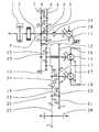
- FIG. 1shows a kinematic diagram of a power split transmission with the working pump arranged coaxial with respect to the input shaft;
- FIG. 2shows a power split transmission with the working pump not arranged coaxially with respect to the input shaft.
- FIG. 1is a diagrammatic representation of FIG. 1 .
- a drive engine 1drives the input shaft 2 of the power split transmission.
- the input shaft 2is connected in a rotationally fixed manner to the spur gear 3 .
- the spur gear 3is operatively connected to the spur gear 4 , wherein the clutch for forward travel 5 and the clutch for reverse travel 6 and the spur gear 3 and the spur gear 4 form the reversing unit 7 .
- the spur gear 8which can be connected to the spur gear 4 via the clutch for reverse travel 6
- the spur gear 9which can be connected to the spur gear 3 via the clutch for forward travel 5
- the spur gear 10is connected in a rotationally fixed manner to the outer central gear 11 of the planetary gear set 12 .
- the planetary gear set 12forms the summation gear for the mechanical power branching and the hydrostatic power branch.
- the inner central gear 13 of the planetary gear set 12is connected in a rotationally fixed manner to the first hydrostatic unit 14 .
- the planetary gear carrier 15is connected in a rotationally fixed manner to the spur gear 16 .
- the spur gear 16is operatively connected to the spur gear 17 , wherein the spur gear 17 is connected in a rotationally fixed manner to the second hydrostatic unit 18 and the gear clutch 19 for the second gear of the reduction gear 20 .
- the spur gear 17is operatively connected to spur gear 21 , which can be connected to spur gear 23 via the gear clutch 22 .
- the spur gear 17can be connected to spur gear 24 via the gear clutch 19 .
- the spur gear 24is operatively connected to spur gear 23 .
- the spur gear 23drives the spur gear 25 and the latter drives in turn the output drive 26 .
- the first hydrostatic unit 14 and the second hydrostatic unit 18are configured as hydrostatic units in a transverse axis design, wherein the displacements can be adjusted via a common component 27 and the hydrostatic units 14 and 18 are arranged adjacent to each other.
- a working pump 28as well as a feed and lubrication pressure pump 29 , is arranged coaxially with respect to the input shaft 2 .
- the first hydrostatic unit 14is adjusted to zero displacement and the second hydrostatic unit 18 is adjusted to its maximum displacement. In this situation, the output drive 26 is at standstill. If the common component 27 is now adjusted, then the first hydrostatic unit 14 is adjusted from its zero displacement and pumps pressurizing medium to the second hydrostatic unit 18 , which is connected to the first hydrostatic unit 14 in a closed circuit. The output drive 26 begins to rotate. At the maximum possible adjustment of the common component 27 , the first hydrostatic unit 14 is at its maximum displacement and the second hydrostatic unit 18 is at zero displacement. The total power is transferred herein exclusively via the mechanical power branch to the output drive 26 .
- the gear clutch 19is likewise operated in an engaging direction toward the engaged gear clutch 22 , wherein either the gear clutch 19 or the gear clutch 22 or both gear clutches are kept in a slip mode until the common component 27 , the first hydrostatic unit 14 , and the second hydrostatic unit 18 are adjusted in such a manner that the displacements and thus the rotational speed of the hydrostatic units 14 and 18 are adapted to the new gear ratio.
- the gear clutch 22is subsequently fully disengaged and the gear clutch 19 is fully engaged.
- the input drivecan now be further modified in its output speed by adjusting the common component 27 .
- FIG. 2
- This figurediffers from FIG. 1 exclusively in that the working pump 28 and the feed and lubrication pressure pump 29 are in drive connection with the spur gear 4 , whereby the working pump 28 and the feed and lubrication pressure pump 29 can be configured with a smaller displacement, since the rotational speed of the spur gear 4 is greater than the rotational speed of the spur gear 3 . It is also possible to only connect the working pump 28 to the spur gear 4 and the feed pump 29 to the input shaft 2 , or the working pump 28 to the input shaft 2 and the feed pump 29 to the spur gear 4 .
Landscapes
- Engineering & Computer Science (AREA)
- General Engineering & Computer Science (AREA)
- Mechanical Engineering (AREA)
- Structure Of Transmissions (AREA)
Abstract
Description
This application is a National Stage completion of PCT/EP2008/060764 filed Aug. 15, 2008, which claims priority from German patent application serial no. 10 2007 047 194.9 filed Oct. 2, 2007.
The invention concerns a power split transmission.
Power split transmissions of this kind have one hydrostatic power branch and one mechanical power branch, which are summed via a summation gear in order to drive an output means.
The hydrostatic-mechanical transmission with power split disclosed inDE 28 54 375 A1 has two shift ranges, and the continuously variable control of the transmission is carried out by means of the hydrostatic power branch.
The invention has as an object the creation of a power split transmission with at least two operating ranges, wherein at least two operating ranges are available in one forward travel direction and in one reverse travel direction, and the transmission is characterized by a simple control of the hydrostatic power branch.
The object is attained with a power split transmission of the specified kind, which has the characteristic features of the main claim.
The power split transmission has one hydrostatic power branch and one mechanical power branch, which are summed in a summation gear. A reversing gear, by means of which the direction of rotation of the transmission input shaft can be reversed depending on the desired direction of travel, is connected upstream of the summation gear.
The summation gear is preferably configured as a planetary gear set for use with the power split transmission in a working machine, for example, a wheel loader, wherein the outer central gear of the planetary gear set is operatively connected to the output shaft of the reversing gear, the sun gear of the planetary gear set is operatively connected to the first hydrostatic unit, and the planetary gear carrier of the planetary gear set is operatively connected to a downstream gear shifting mechanism. The gear shifting mechanism is configured herein as a spur gear unit, whereby the axle offset needed for the wheel loader can be obtained in this combination.
In one embodiment of the invention, a first clutch for forward travel is arranged in the reversing gear coaxially with respect to the input shaft of the power split transmission and the planetary gear set, the gear shifting mechanism and the clutch for reverse travel are arranged outside of the input shaft of the power split transmission, that is, not coaxial thereto. The second hydrostatic unit is operatively connected to the planetary gear carrier of the summation gear, either directly or via a spur gear stage, and is arranged preferably next to the first hydrostatic unit. The first and second hydrostatic units have a common component, by means of which the displacements of the first and of second hydrostatic units can be adjusted simultaneously, wherein the first and second hydrostatic units are configured as hydrostatic units in a transverse axis design. The displacements of the first and of the second hydrostatic unit are configured such that in the first operating mode of the power split transmission with rotating input shaft and stopped output shaft, the common component adjusts the first and the second hydrostatic units in such a way that the first hydrostatic unit, which is operatively connected to the sun gear, is adjusted to zero displacement, and the second hydrostatic unit, which is directly connected in operative connection to the planetary gear carrier, is adjusted to its maximum displacement. In a second mode of operation of the power split transmission at maximum possible rotational speed of the output drive, the displacement of the first hydrostatic unit is adjusted to its maximum displacement, and the displacement of the second hydrostatic unit is adjusted to zero displacement, whereby that the total power is transferred purely mechanically. If the standard transmission is to be shifted from a first gear to a second gear, then the two gear clutches are actuated to engage, wherein at least one of these gear clutches is kept in a slip mode until the load has been transferred from the one gear clutch to the other gear clutch, wherein the gear ratio, that is, the displacement, is reduced during this transfer via the common component by the progressive ratio between the first and the second gear. The power split transmission can be shifted without interruption of tractive force by means of this procedure during range shifting.
Additional features are disclosed in the description of the figures. In the figures:
Adrive engine 1 drives theinput shaft 2 of the power split transmission. Theinput shaft 2 is connected in a rotationally fixed manner to thespur gear 3. Thespur gear 3 is operatively connected to thespur gear 4, wherein the clutch forforward travel 5 and the clutch forreverse travel 6 and thespur gear 3 and thespur gear 4 form thereversing unit 7. Thespur gear 8, which can be connected to thespur gear 4 via the clutch forreverse travel 6, and thespur gear 9, which can be connected to thespur gear 3 via the clutch forforward travel 5, are operatively connected to thespur gear 10. Thespur gear 10 is connected in a rotationally fixed manner to the outercentral gear 11 of theplanetary gear set 12. The planetary gear set12 forms the summation gear for the mechanical power branching and the hydrostatic power branch. The innercentral gear 13 of theplanetary gear set 12 is connected in a rotationally fixed manner to the firsthydrostatic unit 14. Theplanetary gear carrier 15 is connected in a rotationally fixed manner to thespur gear 16. Thespur gear 16 is operatively connected to thespur gear 17, wherein thespur gear 17 is connected in a rotationally fixed manner to the secondhydrostatic unit 18 and thegear clutch 19 for the second gear of thereduction gear 20. Thespur gear 17 is operatively connected tospur gear 21, which can be connected to spurgear 23 via thegear clutch 22. Thespur gear 17 can be connected tospur gear 24 via thegear clutch 19. Thespur gear 24 is operatively connected tospur gear 23. Thespur gear 23 drives thespur gear 25 and the latter drives in turn theoutput drive 26. The firsthydrostatic unit 14 and the secondhydrostatic unit 18 are configured as hydrostatic units in a transverse axis design, wherein the displacements can be adjusted via acommon component 27 and thehydrostatic units pump 28, as well as a feed andlubrication pressure pump 29, is arranged coaxially with respect to theinput shaft 2. For startup in forward travel direction with rotatinginput shaft 2, the clutch forforward travel 5 is engaged, the clutch forreverse travel 6 is open, thegear clutch 19 is disengaged, and thegear clutch 22 is engaged. The firsthydrostatic unit 14 is adjusted to zero displacement and the secondhydrostatic unit 18 is adjusted to its maximum displacement. In this situation, theoutput drive 26 is at standstill. If thecommon component 27 is now adjusted, then the firsthydrostatic unit 14 is adjusted from its zero displacement and pumps pressurizing medium to the secondhydrostatic unit 18, which is connected to the firsthydrostatic unit 14 in a closed circuit. Theoutput drive 26 begins to rotate. At the maximum possible adjustment of thecommon component 27, the firsthydrostatic unit 14 is at its maximum displacement and the secondhydrostatic unit 18 is at zero displacement. The total power is transferred herein exclusively via the mechanical power branch to theoutput drive 26. If the second gear is to be selected, then thegear clutch 19 is likewise operated in an engaging direction toward the engagedgear clutch 22, wherein either thegear clutch 19 or thegear clutch 22 or both gear clutches are kept in a slip mode until thecommon component 27, the firsthydrostatic unit 14, and the secondhydrostatic unit 18 are adjusted in such a manner that the displacements and thus the rotational speed of thehydrostatic units gear clutch 22 is subsequently fully disengaged and thegear clutch 19 is fully engaged. The input drive can now be further modified in its output speed by adjusting thecommon component 27.
This figure differs fromFIG. 1 exclusively in that theworking pump 28 and the feed andlubrication pressure pump 29 are in drive connection with thespur gear 4, whereby theworking pump 28 and the feed andlubrication pressure pump 29 can be configured with a smaller displacement, since the rotational speed of thespur gear 4 is greater than the rotational speed of thespur gear 3. It is also possible to only connect theworking pump 28 to thespur gear 4 and thefeed pump 29 to theinput shaft 2, or theworking pump 28 to theinput shaft 2 and thefeed pump 29 to thespur gear 4.
- 1 Engine
- 2 Input shaft
- 3 Spur gear
- 4 Spur gear
- 5 Clutch for forward travel
- 6 Clutch for reverse travel
- 7 Reversing unit
- 8 Spur gear
- 9 Spur gear
- 10 Spur gear
- 11 Outer central gear
- 12 Planetary gear set
- 13 Inner central gear
- 14 First hydrostatic unit
- 15 Planetary gear carrier
- 16 Spur gear
- 17 Spur gear
- 18 Second hydrostatic unit
- 19 Gear clutch
- 20 Reduction gear
- 21 Spur gear
- 22 Gear clutch
- 23 Spur gear
- 24 Spur gear
- 25 Spur gear
- 26 Output drive
- 27 Common component
- 28 Working pump
- 29 Feed pump
Claims (9)
1. A power split transmission comprising a hydrostatic branch and a mechanical branch which are summed via a summation gear (12),
at least two operating ranges in one forward travel direction and at least two operating ranges in one reverse travel direction,
the hydrostatic branch having a first hydrostatic unit (14) and a second hydrostatic unit (18),
displacement of the first and the second hydrostatic units (14,18) being adjustable via a common component (27) which is connected to the first and the second hydrostatic units (14,19), and
a travel direction clutch for forward travel (5) is concentric with respect to an input shaft (2) of the power split transmission.
2. The power split transmission ofclaim 1 , wherein a gear shifting mechanism (20) is arranged between the summation gear (12) and an output drive (26).
3. The power split transmission ofclaim 2 , wherein, in a first gear, a planetary gear carrier (15) of the summation gear (12) is connectable to the output drive (26) via a first reduction stage of the gear shifting mechanism (20), and, in a second gear, the planetary gear carrier (15) of the summation gear (12) is connectable to the output drive (26) via a second reduction stage of the gear shifting mechanism (20).
4. The power split transmission ofclaim 1 , wherein, when an input shaft (2) rotates and an output drive (26) is at a standstill, the first hydrostatic unit (14) is adjusted to a zero displacement and the second hydrostatic unit (18) is adjusted to a maximum displacement.
5. The power split transmission ofclaim 1 , wherein, when an input shaft (2) rotates and the output drive (26) rotates at a maximum possible speed, the first hydrostatic unit (14) is adjusted to a maximum displacement and the second hydrostatic unit (18) is adjusted to a zero displacement.
6. A power split transmission comprising a hydrostatic branch and a mechanical branch which are summed via a summation gear (12),
at least two operating ranges in one forward travel direction and at least two operating ranges in one reverse travel direction,
the hydrostatic branch having a first hydrostatic unit (14) and a second hydrostatic unit (18), and
displacement of the first and the second hydrostatic units (14,18) being adjustable via a common component (27) which is connected to the first and the second hydrostatic units (14,19),
wherein the summation gear (12) comprises of a planetary gear set, an inner central sun gear (13) of the planetary gear set is connected to the first hydrostatic unit (14) and an outer central annular gear (11) of the planetary gear set is driven by an engine (1), and the second hydrostatic unit (18) is operatively connected to a planetary gear carrier (15) of the planetary gear set.
7. A power split transmission comprising a hydrostatic branch and a mechanical branch which are summed via a summation gear (12),
at least two operating ranges in one forward travel direction and at least two operating ranges in one reverse travel direction,
the hydrostatic branch having a first hydrostatic unit (14) and a second hydrostatic unit (18), and
displacement of the first and the second hydrostatic units (14,18) being adjustable via a common component (27) which is connected to the first and the second hydrostatic units (14,19),
wherein a reversing gear (7) is arranged, in a power flow, between an engine (1) and the summation gear (12).
8. A power split transmission comprising a hydrostatic branch and a mechanical branch which are summed via a summation gear (12),
at least two operating ranges in one forward travel direction and at least two operating ranges in one reverse travel direction,
the hydrostatic branch having a first hydrostatic unit (14) and a second hydrostatic unit (18), and
displacement of the first and the second hydrostatic units (14,18) being adjustable via a common component (27) which is connected to the first and the second hydrostatic units (14,19),
wherein a hydraulic working pump (28) is operatively connected to the input shaft (2) and is concentric with an input shaft (2) of the power split transmission.
9. A power split transmission comprising a hydrostatic branch and a mechanical branch which are summed via a summation gear (12),
at least two operating ranges in one forward travel direction and at least two operating ranges in one reverse travel direction,
the hydrostatic branch having a first hydrostatic unit (14) and a second hydrostatic unit (18), and
displacement of the first and the second hydrostatic units (14,18) being adjustable via a common component (27) which is connected to the first and the second hydrostatic units (14,19),
wherein a hydraulic working pump (28) is operatively connected to an output drive (4) of a travel direction clutch for reverse travel (6) and is concentric with the travel direction clutch (6) for reverse travel of the power split transmission.
Applications Claiming Priority (4)
| Application Number | Priority Date | Filing Date | Title |
|---|---|---|---|
| DE102007047194ADE102007047194A1 (en) | 2007-10-02 | 2007-10-02 | Power split transmission |
| DE102007047194 | 2007-10-02 | ||
| DE102007047194.9 | 2007-10-02 | ||
| PCT/EP2008/060764WO2009047042A1 (en) | 2007-10-02 | 2008-08-15 | Power split transmission |
Publications (2)
| Publication Number | Publication Date |
|---|---|
| US20100197438A1 US20100197438A1 (en) | 2010-08-05 |
| US8323138B2true US8323138B2 (en) | 2012-12-04 |
Family
ID=40090708
Family Applications (1)
| Application Number | Title | Priority Date | Filing Date |
|---|---|---|---|
| US12/679,525Active2029-10-23US8323138B2 (en) | 2007-10-02 | 2008-08-15 | Power split transmission |
Country Status (8)
| Country | Link |
|---|---|
| US (1) | US8323138B2 (en) |
| EP (1) | EP2195557B1 (en) |
| JP (1) | JP5238032B2 (en) |
| KR (1) | KR101389104B1 (en) |
| CN (1) | CN101809330B (en) |
| AT (1) | ATE535735T1 (en) |
| DE (1) | DE102007047194A1 (en) |
| WO (1) | WO2009047042A1 (en) |
Cited By (1)
| Publication number | Priority date | Publication date | Assignee | Title |
|---|---|---|---|---|
| US20160281831A1 (en)* | 2013-03-19 | 2016-09-29 | Zf Friedrichshafen Ag | Gearing device with secondarily coupled power split |
Families Citing this family (20)
| Publication number | Priority date | Publication date | Assignee | Title |
|---|---|---|---|---|
| DE102008001613A1 (en) | 2008-05-07 | 2009-11-12 | Zf Friedrichshafen Ag | Continuously variable transmission, with two power paths, has a hydrostatic unit for the first path and a mechanical unit for the second path |
| DE102009001602A1 (en)* | 2009-03-17 | 2010-09-23 | Zf Friedrichshafen Ag | Device for a vehicle drive train with a transmission device |
| US8696509B2 (en) | 2009-07-27 | 2014-04-15 | Dana Italia Spa | Power split transmission |
| DE102009045087B4 (en)* | 2009-09-29 | 2022-06-15 | Zf Friedrichshafen Ag | Transmission device with power split |
| DE102010001697A1 (en) | 2010-02-09 | 2011-08-11 | ZF Friedrichshafen AG, 88046 | Gearbox device has hydrostatic device formed by two hydrostatic shafts, where each of multiple switching elements is arranged on separate countershaft, and each of multiple switching elements is arranged on separate countershaft |
| DE102010001698A1 (en) | 2010-02-09 | 2011-08-11 | ZF Friedrichshafen AG, 88046 | Transmission device with power split |
| DE102010001699A1 (en) | 2010-02-09 | 2011-08-11 | ZF Friedrichshafen AG, 88046 | Gearbox device has hydrostatic device formed by two hydrostatic shafts, where each of multiple switching elements is arranged on separate countershaft, and torque is guided over gear wheel in direction of gearbox output shaft |
| RU2013105451A (en) | 2010-07-09 | 2014-08-20 | Мали Холдинг Аг | HYDRAULIC HYDROSTATIC-MECHANICAL TRANSMISSION WITH DIVISION OF POWER FLOW, METHOD OF OPERATION OF SUCH TRANSMISSION WITH DIVISION OF POWER FLOW, AND ALSO WHEEL LOADER WITH SUCH TRANSFER DIVISION |
| CN102146987B (en)* | 2011-01-18 | 2013-02-06 | 王云高 | Power shift speed changing box for matching engineering machine |
| DE102012108857B4 (en)* | 2012-09-20 | 2022-01-13 | Linde Hydraulics Gmbh & Co. Kg | Hydrostatic starter device for an internal combustion engine |
| DE102013204746A1 (en) | 2013-03-19 | 2014-09-25 | Zf Friedrichshafen Ag | Transmission device with secondary coupled power split |
| FR3006027B1 (en)* | 2013-05-24 | 2015-06-05 | Technoboost | METHOD FOR OPERATING A TRACTION CHAIN OF A HYBRID VEHICLE FOR REVERSE STARTS |
| DE102013220919B4 (en) | 2013-10-16 | 2022-01-13 | Zf Friedrichshafen Ag | Method of controlling a continuously variable transmission |
| DE102015223250A1 (en)* | 2015-11-25 | 2017-06-01 | Zf Friedrichshafen Ag | Power split transmission |
| DE102016200755A1 (en) | 2016-01-20 | 2017-07-20 | Avl Commercial Driveline & Tractor Engineering Gmbh | Stepless, hydrostatic-mechanical power split transmission and commercial vehicle with such a power split transmission |
| DE102016221126A1 (en) | 2016-10-26 | 2018-04-26 | Zf Friedrichshafen Ag | Method for performing a cold start |
| DE102017204285A1 (en) | 2017-03-15 | 2018-09-20 | Zf Friedrichshafen Ag | Method and control device for operating a drive train |
| DE102018218924A1 (en)* | 2018-11-06 | 2020-05-07 | Zf Friedrichshafen Ag | Method for switching off a transmission of a work machine |
| DE102019200079A1 (en) | 2019-01-07 | 2020-07-09 | Zf Friedrichshafen Ag | Method and control device for loading a work tool of a work machine |
| JP7419064B2 (en)* | 2019-12-27 | 2024-01-22 | 株式会社クボタ | work vehicle |
Citations (72)
| Publication number | Priority date | Publication date | Assignee | Title |
|---|---|---|---|---|
| US2583656A (en) | 1950-02-01 | 1952-01-29 | Lay Corp | Hydraulic automatic selective transmission, including tilt plates |
| US2808737A (en) | 1952-04-01 | 1957-10-08 | Bullard Co | Variable-speed transmission and method of operation |
| AT197650B (en) | 1951-09-19 | 1958-05-10 | Cambi Idraulici Badalini Spa | Infinitely variable fluid transmission |
| DE1069978B (en) | 1959-11-26 | Daimller-Benz Aktiengesellschaft, Stiuttgart-Untertürkheim | ||
| FR1197751A (en) | 1957-01-07 | 1959-12-02 | Von Roll Ag | Hydraulic control applicable to a hydrostatic mechanism for a tracked or wheeled vehicle |
| US3023638A (en) | 1959-11-10 | 1962-03-06 | Hobson Ltd H M | Constant speed units |
| DE976055C (en) | 1955-05-24 | 1963-01-31 | Heinrich Dr-Ing Ebert | Hydrostatic transmission, especially for motor vehicles |
| DE1174126B (en) | 1961-02-02 | 1964-07-16 | Linde Eismasch Ag | Infinitely variable transmission |
| US3204486A (en) | 1963-03-06 | 1965-09-07 | Lalio George M De | Infinitely variable power transmission |
| US3212358A (en) | 1962-01-16 | 1965-10-19 | Lalio George M De | Continuously variable power transmission |
| FR1483053A (en) | 1966-05-06 | 1967-06-02 | Fendt & Co Xaver | Device for controlling a hydrostatic power converter and vehicle provided with said device |
| DE1952966A1 (en) | 1968-10-21 | 1970-04-23 | Urs Systems Corp | Power transmission device |
| GB1206196A (en) | 1967-03-29 | 1970-09-23 | Daimler Benz Ag | Infinitely variable hydrostatic transmission for vehicles, especially for motor vehicles |
| US3601981A (en) | 1969-11-03 | 1971-08-31 | Lucas Industries Ltd | Control systems for hydraulic transmission systems |
| US3626787A (en) | 1969-11-24 | 1971-12-14 | White Motor Corp | Continuously variable transmission |
| US3714845A (en) | 1971-08-24 | 1973-02-06 | Gen Motors Corp | Hydromechanical transmission |
| US3834164A (en) | 1972-01-26 | 1974-09-10 | Kopat Ges Entwicklung Und Pate | Hydrostatic torque converter |
| US4019404A (en) | 1975-03-21 | 1977-04-26 | Sundstrand Corporation | Power transmission |
| US4024775A (en)* | 1975-07-09 | 1977-05-24 | Caterpillar Tractor Co. | Hydrostatic mechanical transmission and controls therefor |
| DE2757399A1 (en) | 1977-03-04 | 1978-09-07 | Sundstrand Corp | MANUAL TRANSMISSION |
| DE2854375A1 (en) | 1978-12-16 | 1980-06-19 | Zahnradfabrik Friedrichshafen | HYDROSTATIC-MECHANICAL GEARBOX WITH POWER BRANCHING |
| DE2904572A1 (en) | 1979-02-07 | 1980-08-14 | Maschf Augsburg Nuernberg Ag | Vehicle drive with differential output gearbox - has two sun-wheels of different dia. meshing with double planetary pinions on carrier strip |
| DE2844116A1 (en) | 1977-10-10 | 1982-07-22 | Le Moteur Moderne, 92100 Boulogne-Billancourt, Hauts-de-Seine | HYDROMECHANICAL TRANSMISSION FOR CONTINUOUSLY CHANGING THE RATIO OF AN INPUT AND OUTPUT SHAFT AND REVERSING THE DIRECTION OF ROTATION OF THE OUTPUT SHAFT |
| US4446756A (en) | 1979-12-15 | 1984-05-08 | Maschinenfabrik Augsburg-Nurnberg Aktiengesellschaft | Power divider gearbox with a planetary differential gear drive |
| DE8018579U1 (en) | 1980-07-10 | 1984-06-07 | J.M. Voith Gmbh, 7920 Heidenheim | Drive unit with a drive machine and a flywheel |
| US4563914A (en) | 1982-01-10 | 1986-01-14 | Industries Development Corporation (International Services) | Continuously variable transmission with auxiliary drive |
| WO1986000963A1 (en) | 1984-07-30 | 1986-02-13 | Sauer Italiana S.P.A. | Manual and automatic governor for a hydrostatic transmission |
| DE3622045A1 (en) | 1985-09-18 | 1987-03-26 | Michael Meyerle | CONTINUOUSLY HYDROMECHANICAL BRANCHING GEARBOX, ESPECIALLY FOR MOTOR VEHICLES |
| EP0234135A1 (en) | 1986-02-24 | 1987-09-02 | Shimadzu Corporation | Hydromechanical transmission |
| EP0234136A1 (en) | 1986-02-24 | 1987-09-02 | Shimadzu Corporation | Hydromechanical transmission |
| EP0235466A1 (en) | 1986-02-24 | 1987-09-09 | Shimadzu Corporation | Hydromechanical transmission |
| US4976664A (en) | 1988-07-27 | 1990-12-11 | Man Nutzfahrzeuge Aktiengesellschaft Of Munchen | Vehicle drive transmission having a high power ratio |
| US5071391A (en) | 1986-11-21 | 1991-12-10 | Shimadzu Corporation | Stepless speed changing hydrostatic transmission |
| EP0465752A1 (en) | 1990-06-20 | 1992-01-15 | Aragonesa De Equipamientos Para Automoviles, S.A. | Continuous gear change mechanism |
| DE4206023A1 (en) | 1992-02-27 | 1993-09-16 | Man Nutzfahrzeuge Ag | Continuously variable hydrostatic-mechanical transmission e.g. for independent drives in road vehicles - has split transmission with pair of hydrostatic units coupled to engine via gearbox and with output controlled by valves coupled to electrical controller |
| EP0577282A1 (en) | 1992-06-27 | 1994-01-05 | Massey Ferguson S.A. | Transmission |
| DE9402493U1 (en) | 1994-02-16 | 1995-06-14 | O & K Orenstein & Koppel Ag, 13581 Berlin | Power shift transmission, in particular for mobile construction and work machines |
| DE4443267A1 (en) | 1994-12-05 | 1996-06-13 | Claas Ohg | Powershift transmission with 5-shaft epicyclic gear |
| US5667452A (en) | 1995-04-06 | 1997-09-16 | Caterpillar Inc. | Split torque transmission |
| EP0683875B1 (en) | 1993-12-18 | 1998-04-08 | J.M. Voith GmbH | Continuously variable hydrostatic power-split transmission |
| DE19751993A1 (en) | 1996-11-25 | 1998-05-28 | Caterpillar Inc | Hydrostatic gear combined with mechanical gear |
| US5868640A (en) | 1996-12-04 | 1999-02-09 | Caterpillar Inc. | Hydromechanical transmission having four members and two planetaries |
| WO1999015813A2 (en) | 1997-09-20 | 1999-04-01 | Michael Meyerle | Continuously variable transmission, especially with power branching |
| US6029542A (en) | 1997-09-09 | 2000-02-29 | Steyr-Daimler-Puch Aktiengesellschaft | Power-split gear and its installation in a gear case |
| US6056661A (en) | 1999-06-14 | 2000-05-02 | General Motors Corporation | Multi-range transmission with input split planetary gear set and continuously variable transmission unit |
| WO2000043695A2 (en) | 1999-01-25 | 2000-07-27 | Michael Meyerle | Continuously variable hydrostatic-mechanical power split transmission |
| DE19954894A1 (en) | 1999-05-25 | 2000-12-21 | Liebherr Markus | Power split transmission |
| US6358174B1 (en)* | 1997-11-12 | 2002-03-19 | Folsom Technologies, Inc. | Hydraulic machine |
| US20020042319A1 (en) | 2000-09-26 | 2002-04-11 | Deere & Company, A Delaware Corporation | Transmission assembly with infinitely variable and constant transmission modules |
| US6485387B1 (en) | 2000-09-26 | 2002-11-26 | Deere & Company | Apparatus and method for determining the output speed of a hydrostatic unit in a hydro-mechanical transmission |
| DE20208495U1 (en) | 2002-06-01 | 2003-01-23 | Rainer, Johann, Dipl.-Ing. (FH), 84177 Gottfrieding | Continuous, dual power branching gearbox for vehicle has two parallel mutually engaged planetary gears, each with sun wheel, planetary bearer, planetary and hollow wheels |
| US20030089107A1 (en) | 2001-02-19 | 2003-05-15 | Nobuyuki Tani | Power unit |
| US20030150662A1 (en) | 2001-02-14 | 2003-08-14 | Nobuyuki Tani | Hydromechanical speedchange device and vehicle having speed change device mounted thereon |
| US20030166430A1 (en) | 1998-11-24 | 2003-09-04 | Folsom Technologies, Inc. | Parallel hydromechanical underdrive transmission |
| WO2004038257A1 (en) | 2002-10-22 | 2004-05-06 | Luk Lamellen Und Kupplungsbau Beteiligungs Kg | Power-split transmission having an infinitely variable ratio |
| US6761658B1 (en) | 2003-02-14 | 2004-07-13 | Deere & Company | Four mode hydro-mechanical transmission |
| DE10319252A1 (en) | 2003-04-28 | 2004-11-18 | Claas Industrietechnik Gmbh | Infinitely variable torque division gearbox for agricultural tractors and utility vehicles has a continuously adjustable ratio of speeds, two engaging/disengaging clutches and a driven shaft |
| US20040242357A1 (en) | 2003-05-27 | 2004-12-02 | Komatsu Ltd. | Hydromechanical transmission |
| EP1541898A2 (en) | 2003-12-12 | 2005-06-15 | CNH Italia S.p.A. | CVT transmission for motor vehicles, in particular for tractors |
| WO2006042434A1 (en) | 2004-10-20 | 2006-04-27 | Markus Liebherr International Ag | Power-branched transmission and method for the operation of such a transmission |
| US20060094554A1 (en) | 2004-10-28 | 2006-05-04 | Schmidt Michael R | Two-mode compound-split hydraulic continuously variable transmission |
| DE102006004223A1 (en) | 2005-01-31 | 2006-08-10 | Sauer-Danfoss Inc. | Method and means for switching a hydromechanical transmission |
| US20060276291A1 (en) | 2005-06-03 | 2006-12-07 | Fabry Mark D | Hydromechanical transmission |
| WO2007014706A1 (en) | 2005-08-02 | 2007-02-08 | Gloeckler Dieter | Transmission unit, particularly multirange transmission |
| JP2007085517A (en) | 2005-09-26 | 2007-04-05 | Kubota Corp | Variable speed transmission |
| EP1855029A2 (en) | 2006-05-11 | 2007-11-14 | CNH Italia S.p.A. | CVT hydromechanical drive, in particular for a farm tractor. |
| US20070277520A1 (en) | 2006-05-31 | 2007-12-06 | Sauer-Danfoss Inc | Hydraulic module with two integrated swashplate or oblique axis drive units |
| DE102006025348A1 (en) | 2006-05-31 | 2007-12-06 | Sauer-Danfoss Gmbh & Co Ohg | Hydrostatic-mechanical transmission |
| WO2008004360A1 (en) | 2006-07-06 | 2008-01-10 | Kubota Corporation | Shifting and power transmission device |
| DE112004000874B4 (en) | 2003-05-21 | 2008-04-30 | Komatsu Ltd. | transmission |
| US20080103006A1 (en) | 2006-10-30 | 2008-05-01 | Sauer-Danfoss Inc. | Hydromechanical transmission with input summer |
| EP1930627A1 (en) | 2005-09-30 | 2008-06-11 | Kubota Corporation | Speed change transmission device |
Family Cites Families (2)
| Publication number | Priority date | Publication date | Assignee | Title |
|---|---|---|---|---|
| JP4570418B2 (en)* | 2003-09-16 | 2010-10-27 | 株式会社小松製作所 | Control device for hydraulic-mechanical transmission |
| DE102004044510A1 (en)* | 2004-09-15 | 2006-03-30 | Zf Friedrichshafen Ag | Hydraulic transmission |
- 2007
- 2007-10-02DEDE102007047194Apatent/DE102007047194A1/ennot_activeWithdrawn
- 2008
- 2008-08-15CNCN2008801086799Apatent/CN101809330B/enactiveActive
- 2008-08-15EPEP08803056Apatent/EP2195557B1/enactiveActive
- 2008-08-15USUS12/679,525patent/US8323138B2/enactiveActive
- 2008-08-15WOPCT/EP2008/060764patent/WO2009047042A1/enactiveApplication Filing
- 2008-08-15KRKR1020107006994Apatent/KR101389104B1/enactiveActive
- 2008-08-15ATAT08803056Tpatent/ATE535735T1/enactive
- 2008-08-15JPJP2010527381Apatent/JP5238032B2/enactiveActive
Patent Citations (101)
| Publication number | Priority date | Publication date | Assignee | Title |
|---|---|---|---|---|
| DE1069978B (en) | 1959-11-26 | Daimller-Benz Aktiengesellschaft, Stiuttgart-Untertürkheim | ||
| US2583656A (en) | 1950-02-01 | 1952-01-29 | Lay Corp | Hydraulic automatic selective transmission, including tilt plates |
| AT197650B (en) | 1951-09-19 | 1958-05-10 | Cambi Idraulici Badalini Spa | Infinitely variable fluid transmission |
| US2808737A (en) | 1952-04-01 | 1957-10-08 | Bullard Co | Variable-speed transmission and method of operation |
| DE976055C (en) | 1955-05-24 | 1963-01-31 | Heinrich Dr-Ing Ebert | Hydrostatic transmission, especially for motor vehicles |
| FR1197751A (en) | 1957-01-07 | 1959-12-02 | Von Roll Ag | Hydraulic control applicable to a hydrostatic mechanism for a tracked or wheeled vehicle |
| US3023638A (en) | 1959-11-10 | 1962-03-06 | Hobson Ltd H M | Constant speed units |
| DE1174126B (en) | 1961-02-02 | 1964-07-16 | Linde Eismasch Ag | Infinitely variable transmission |
| US3212358A (en) | 1962-01-16 | 1965-10-19 | Lalio George M De | Continuously variable power transmission |
| US3204486A (en) | 1963-03-06 | 1965-09-07 | Lalio George M De | Infinitely variable power transmission |
| FR1483053A (en) | 1966-05-06 | 1967-06-02 | Fendt & Co Xaver | Device for controlling a hydrostatic power converter and vehicle provided with said device |
| GB1206196A (en) | 1967-03-29 | 1970-09-23 | Daimler Benz Ag | Infinitely variable hydrostatic transmission for vehicles, especially for motor vehicles |
| DE1952966A1 (en) | 1968-10-21 | 1970-04-23 | Urs Systems Corp | Power transmission device |
| US3580107A (en)* | 1968-10-21 | 1971-05-25 | Urs Systems Corp | Transmission |
| US3601981A (en) | 1969-11-03 | 1971-08-31 | Lucas Industries Ltd | Control systems for hydraulic transmission systems |
| US3626787A (en) | 1969-11-24 | 1971-12-14 | White Motor Corp | Continuously variable transmission |
| US3714845A (en) | 1971-08-24 | 1973-02-06 | Gen Motors Corp | Hydromechanical transmission |
| US3834164A (en) | 1972-01-26 | 1974-09-10 | Kopat Ges Entwicklung Und Pate | Hydrostatic torque converter |
| US4019404A (en) | 1975-03-21 | 1977-04-26 | Sundstrand Corporation | Power transmission |
| US4024775A (en)* | 1975-07-09 | 1977-05-24 | Caterpillar Tractor Co. | Hydrostatic mechanical transmission and controls therefor |
| DE2757399A1 (en) | 1977-03-04 | 1978-09-07 | Sundstrand Corp | MANUAL TRANSMISSION |
| US4121479A (en) | 1977-03-04 | 1978-10-24 | Sundstrand Corporation | Power transmission |
| DE2844116A1 (en) | 1977-10-10 | 1982-07-22 | Le Moteur Moderne, 92100 Boulogne-Billancourt, Hauts-de-Seine | HYDROMECHANICAL TRANSMISSION FOR CONTINUOUSLY CHANGING THE RATIO OF AN INPUT AND OUTPUT SHAFT AND REVERSING THE DIRECTION OF ROTATION OF THE OUTPUT SHAFT |
| US4434681A (en) | 1978-12-16 | 1984-03-06 | Zahnradfabrik Friedrichshafen Ag | Hydromechanical drive |
| DE2854375A1 (en) | 1978-12-16 | 1980-06-19 | Zahnradfabrik Friedrichshafen | HYDROSTATIC-MECHANICAL GEARBOX WITH POWER BRANCHING |
| DE2904572A1 (en) | 1979-02-07 | 1980-08-14 | Maschf Augsburg Nuernberg Ag | Vehicle drive with differential output gearbox - has two sun-wheels of different dia. meshing with double planetary pinions on carrier strip |
| US4446756A (en) | 1979-12-15 | 1984-05-08 | Maschinenfabrik Augsburg-Nurnberg Aktiengesellschaft | Power divider gearbox with a planetary differential gear drive |
| DE8018579U1 (en) | 1980-07-10 | 1984-06-07 | J.M. Voith Gmbh, 7920 Heidenheim | Drive unit with a drive machine and a flywheel |
| US4563914A (en) | 1982-01-10 | 1986-01-14 | Industries Development Corporation (International Services) | Continuously variable transmission with auxiliary drive |
| WO1986000963A1 (en) | 1984-07-30 | 1986-02-13 | Sauer Italiana S.P.A. | Manual and automatic governor for a hydrostatic transmission |
| DE3622045A1 (en) | 1985-09-18 | 1987-03-26 | Michael Meyerle | CONTINUOUSLY HYDROMECHANICAL BRANCHING GEARBOX, ESPECIALLY FOR MOTOR VEHICLES |
| EP0234135A1 (en) | 1986-02-24 | 1987-09-02 | Shimadzu Corporation | Hydromechanical transmission |
| EP0234136A1 (en) | 1986-02-24 | 1987-09-02 | Shimadzu Corporation | Hydromechanical transmission |
| EP0235466A1 (en) | 1986-02-24 | 1987-09-09 | Shimadzu Corporation | Hydromechanical transmission |
| US4776233A (en) | 1986-02-24 | 1988-10-11 | Shimadzu Corporation | Hydromechanical transmission and hydromechanical speed-change mechanism |
| US4813306A (en) | 1986-02-24 | 1989-03-21 | Shimadzu Corporation | Hydromechanical transmission |
| DE3786996T2 (en) | 1986-11-21 | 1993-12-23 | Shimadzu Corp | Continuously variable transmission. |
| US5071391A (en) | 1986-11-21 | 1991-12-10 | Shimadzu Corporation | Stepless speed changing hydrostatic transmission |
| US4976664A (en) | 1988-07-27 | 1990-12-11 | Man Nutzfahrzeuge Aktiengesellschaft Of Munchen | Vehicle drive transmission having a high power ratio |
| EP0465752A1 (en) | 1990-06-20 | 1992-01-15 | Aragonesa De Equipamientos Para Automoviles, S.A. | Continuous gear change mechanism |
| DE4206023A1 (en) | 1992-02-27 | 1993-09-16 | Man Nutzfahrzeuge Ag | Continuously variable hydrostatic-mechanical transmission e.g. for independent drives in road vehicles - has split transmission with pair of hydrostatic units coupled to engine via gearbox and with output controlled by valves coupled to electrical controller |
| EP0577282A1 (en) | 1992-06-27 | 1994-01-05 | Massey Ferguson S.A. | Transmission |
| US5421790A (en) | 1992-06-27 | 1995-06-06 | Massey-Ferguson S.A. | Continuously variable transmission |
| EP0683875B1 (en) | 1993-12-18 | 1998-04-08 | J.M. Voith GmbH | Continuously variable hydrostatic power-split transmission |
| US5766107A (en) | 1993-12-18 | 1998-06-16 | J.M. Voith Gmbh | Continuous hydrostatic power division transmission |
| DE9402493U1 (en) | 1994-02-16 | 1995-06-14 | O & K Orenstein & Koppel Ag, 13581 Berlin | Power shift transmission, in particular for mobile construction and work machines |
| DE4443267A1 (en) | 1994-12-05 | 1996-06-13 | Claas Ohg | Powershift transmission with 5-shaft epicyclic gear |
| US5643122A (en) | 1994-12-05 | 1997-07-01 | Claas Kommanditgesellschaft Auf Aktien | Power transmission with 5-stage planetary gear unit |
| US5667452A (en) | 1995-04-06 | 1997-09-16 | Caterpillar Inc. | Split torque transmission |
| DE19751993A1 (en) | 1996-11-25 | 1998-05-28 | Caterpillar Inc | Hydrostatic gear combined with mechanical gear |
| US5890981A (en) | 1996-11-25 | 1999-04-06 | Caterpillar Inc. | Hydromechanical transmission having three planetaries and five members |
| US5868640A (en) | 1996-12-04 | 1999-02-09 | Caterpillar Inc. | Hydromechanical transmission having four members and two planetaries |
| US6029542A (en) | 1997-09-09 | 2000-02-29 | Steyr-Daimler-Puch Aktiengesellschaft | Power-split gear and its installation in a gear case |
| DE19843069A1 (en) | 1997-09-20 | 1999-05-06 | Michael Meyerle | Continuously variable transmission, especially with power branching |
| WO1999015813A3 (en) | 1997-09-20 | 1999-10-07 | Michael Meyerle | Continuously variable transmission, especially with power branching |
| WO1999015813A2 (en) | 1997-09-20 | 1999-04-01 | Michael Meyerle | Continuously variable transmission, especially with power branching |
| US6358174B1 (en)* | 1997-11-12 | 2002-03-19 | Folsom Technologies, Inc. | Hydraulic machine |
| US20030166430A1 (en) | 1998-11-24 | 2003-09-04 | Folsom Technologies, Inc. | Parallel hydromechanical underdrive transmission |
| WO2000043695A2 (en) | 1999-01-25 | 2000-07-27 | Michael Meyerle | Continuously variable hydrostatic-mechanical power split transmission |
| DE10003174A1 (en) | 1999-01-25 | 2000-09-21 | Michael Meyerle | Continuously variable hydrostatic-mechanical split transmission regulates hydrostatic unit speed so coupling elements to be closed are stationary or synchronised |
| WO2000043695A3 (en) | 1999-01-25 | 2001-02-01 | Michael Meyerle | Continuously variable hydrostatic-mechanical power split transmission |
| DE19954894A1 (en) | 1999-05-25 | 2000-12-21 | Liebherr Markus | Power split transmission |
| US6056661A (en) | 1999-06-14 | 2000-05-02 | General Motors Corporation | Multi-range transmission with input split planetary gear set and continuously variable transmission unit |
| US6485387B1 (en) | 2000-09-26 | 2002-11-26 | Deere & Company | Apparatus and method for determining the output speed of a hydrostatic unit in a hydro-mechanical transmission |
| DE60103717T2 (en) | 2000-09-26 | 2004-10-28 | Deere & Company, Moline | Hydromechanical transmission |
| US20020042319A1 (en) | 2000-09-26 | 2002-04-11 | Deere & Company, A Delaware Corporation | Transmission assembly with infinitely variable and constant transmission modules |
| DE10047398A1 (en) | 2000-09-26 | 2002-04-11 | Deere & Co | Gear synthesis with stepless and constant gear modules |
| US6592485B2 (en) | 2000-09-26 | 2003-07-15 | Deere & Company | Transmission assembly with infinitely variable and constant transmission modules |
| US20030150662A1 (en) | 2001-02-14 | 2003-08-14 | Nobuyuki Tani | Hydromechanical speedchange device and vehicle having speed change device mounted thereon |
| US20030089107A1 (en) | 2001-02-19 | 2003-05-15 | Nobuyuki Tani | Power unit |
| DE20208495U1 (en) | 2002-06-01 | 2003-01-23 | Rainer, Johann, Dipl.-Ing. (FH), 84177 Gottfrieding | Continuous, dual power branching gearbox for vehicle has two parallel mutually engaged planetary gears, each with sun wheel, planetary bearer, planetary and hollow wheels |
| WO2004038257A1 (en) | 2002-10-22 | 2004-05-06 | Luk Lamellen Und Kupplungsbau Beteiligungs Kg | Power-split transmission having an infinitely variable ratio |
| US7097583B2 (en) | 2002-10-22 | 2006-08-29 | Luk Lamellen Und Kupplungsbau Beteiligungs Kg | Power-branched transmission with steplessly adjustable transmission ratio |
| US6761658B1 (en) | 2003-02-14 | 2004-07-13 | Deere & Company | Four mode hydro-mechanical transmission |
| WO2004072512A1 (en) | 2003-02-14 | 2004-08-26 | Deere & Company | Four mode hydro-mechanical transmission |
| DE10319252A1 (en) | 2003-04-28 | 2004-11-18 | Claas Industrietechnik Gmbh | Infinitely variable torque division gearbox for agricultural tractors and utility vehicles has a continuously adjustable ratio of speeds, two engaging/disengaging clutches and a driven shaft |
| US7448976B2 (en) | 2003-05-21 | 2008-11-11 | Komatsu Ltd. | Speed-changing device |
| DE112004000874B4 (en) | 2003-05-21 | 2008-04-30 | Komatsu Ltd. | transmission |
| US20040242357A1 (en) | 2003-05-27 | 2004-12-02 | Komatsu Ltd. | Hydromechanical transmission |
| EP1541898A2 (en) | 2003-12-12 | 2005-06-15 | CNH Italia S.p.A. | CVT transmission for motor vehicles, in particular for tractors |
| WO2006042434A1 (en) | 2004-10-20 | 2006-04-27 | Markus Liebherr International Ag | Power-branched transmission and method for the operation of such a transmission |
| US20080214349A1 (en) | 2004-10-20 | 2008-09-04 | Markus Liebherr International Ag | Power-Branched Transmission and Method For the Operation of Such a Transmission |
| US20060094554A1 (en) | 2004-10-28 | 2006-05-04 | Schmidt Michael R | Two-mode compound-split hydraulic continuously variable transmission |
| US7354368B2 (en) | 2005-01-31 | 2008-04-08 | Sauer-Danfoss Inc. | Method and means for shifting a hydromechanical transmission |
| DE102006004223A1 (en) | 2005-01-31 | 2006-08-10 | Sauer-Danfoss Inc. | Method and means for switching a hydromechanical transmission |
| US20060276291A1 (en) | 2005-06-03 | 2006-12-07 | Fabry Mark D | Hydromechanical transmission |
| WO2007014706A1 (en) | 2005-08-02 | 2007-02-08 | Gloeckler Dieter | Transmission unit, particularly multirange transmission |
| US20100056318A1 (en) | 2005-08-02 | 2010-03-04 | Gloeckler Dieter | Transmission unit, in particular a multi-range transmission |
| JP2007085517A (en) | 2005-09-26 | 2007-04-05 | Kubota Corp | Variable speed transmission |
| EP1930627A1 (en) | 2005-09-30 | 2008-06-11 | Kubota Corporation | Speed change transmission device |
| US20080214351A1 (en) | 2005-09-30 | 2008-09-04 | Kubota Corporation | Speed-Change Transmission Apparatus |
| US20080085801A1 (en) | 2006-05-11 | 2008-04-10 | Enrico Sedoni | CVT hydromechanical drive |
| EP1855029A2 (en) | 2006-05-11 | 2007-11-14 | CNH Italia S.p.A. | CVT hydromechanical drive, in particular for a farm tractor. |
| DE102006025347B3 (en) | 2006-05-31 | 2007-12-27 | Sauer-Danfoss Gmbh & Co Ohg | Hydromodule with two integrated swash plate or oblique axis engines |
| US20070281815A1 (en) | 2006-05-31 | 2007-12-06 | Sauer-Danfoss Inc. | Hydrostatic mechanical gearbox |
| DE102006025348A1 (en) | 2006-05-31 | 2007-12-06 | Sauer-Danfoss Gmbh & Co Ohg | Hydrostatic-mechanical transmission |
| US20070277520A1 (en) | 2006-05-31 | 2007-12-06 | Sauer-Danfoss Inc | Hydraulic module with two integrated swashplate or oblique axis drive units |
| WO2008004360A1 (en) | 2006-07-06 | 2008-01-10 | Kubota Corporation | Shifting and power transmission device |
| US20090270212A1 (en) | 2006-07-06 | 2009-10-29 | Kubota Corporation | Speed Change Transmission Apparatus |
| US20080103006A1 (en) | 2006-10-30 | 2008-05-01 | Sauer-Danfoss Inc. | Hydromechanical transmission with input summer |
| DE102007049412A1 (en) | 2006-10-30 | 2008-05-08 | Sauer-Danfoss Inc. | Hydromechanical power split transmission with input totalizer |
Cited By (2)
| Publication number | Priority date | Publication date | Assignee | Title |
|---|---|---|---|---|
| US20160281831A1 (en)* | 2013-03-19 | 2016-09-29 | Zf Friedrichshafen Ag | Gearing device with secondarily coupled power split |
| US9810305B2 (en)* | 2013-03-19 | 2017-11-07 | Zf Friedrichshafen Ag | Gearing device with secondarily coupled power split |
Also Published As
| Publication number | Publication date |
|---|---|
| KR101389104B1 (en) | 2014-04-25 |
| DE102007047194A1 (en) | 2009-04-09 |
| KR20100066530A (en) | 2010-06-17 |
| JP2010540869A (en) | 2010-12-24 |
| EP2195557B1 (en) | 2011-11-30 |
| JP5238032B2 (en) | 2013-07-17 |
| ATE535735T1 (en) | 2011-12-15 |
| US20100197438A1 (en) | 2010-08-05 |
| EP2195557A1 (en) | 2010-06-16 |
| CN101809330B (en) | 2012-05-30 |
| WO2009047042A1 (en) | 2009-04-16 |
| CN101809330A (en) | 2010-08-18 |
Similar Documents
| Publication | Publication Date | Title |
|---|---|---|
| US8323138B2 (en) | Power split transmission | |
| US8328676B2 (en) | Power split transmission | |
| US8696509B2 (en) | Power split transmission | |
| US8469850B2 (en) | Superposition transmission | |
| US6447422B1 (en) | Dual mode, geared neutral continuously variable transmission | |
| CA2344870C (en) | Hydro-mechanical transmission | |
| EP1061288A2 (en) | A continuously variable multi-range powertrain with a geared neutral | |
| US20030036451A1 (en) | Continuously variable hydro-mechanical transmission | |
| EP1061287A2 (en) | Multiple range continuously variable transmission | |
| WO2004104449A1 (en) | Speed-changing device | |
| US3982448A (en) | Input-split hydromechanical transmission | |
| US11293528B2 (en) | Working vehicle | |
| CN101213389A (en) | ratio limiting device | |
| EP3168498A1 (en) | Hydromechanical power split transmission assembly | |
| EP2955418B1 (en) | A variator-assisted transmission | |
| US6315691B1 (en) | Toothed selector clutch | |
| US6561942B2 (en) | Dual mode variable ratio transmission | |
| EP2118523B1 (en) | Method for controlling two variable displacement hydrostatic units in an infinitely variable hydro-mechanical transmission | |
| US8371979B2 (en) | Transmission unit, particularly range-change transmission | |
| CN108591411B (en) | A Transmission System That Can Realize Three Variable Speed Transmission Processes | |
| US8535190B2 (en) | Transmission device with power splitting | |
| US10322723B2 (en) | Variator-assisted transmission and launch control methods for such a transmission | |
| US20020082130A1 (en) | Hydromechanical transmission | |
| WO2007022209A1 (en) | Continuously variable transmission | |
| KR101326416B1 (en) | Transmission of vehicle |
Legal Events
| Date | Code | Title | Description |
|---|---|---|---|
| AS | Assignment | Owner name:ZF FRIEDRICHSHAFEN AG, GERMANY Free format text:ASSIGNMENT OF ASSIGNORS INTEREST;ASSIGNOR:LEGNER, JURGEN;REEL/FRAME:024173/0837 Effective date:20100212 | |
| FEPP | Fee payment procedure | Free format text:PAYOR NUMBER ASSIGNED (ORIGINAL EVENT CODE: ASPN); ENTITY STATUS OF PATENT OWNER: LARGE ENTITY | |
| STCF | Information on status: patent grant | Free format text:PATENTED CASE | |
| FPAY | Fee payment | Year of fee payment:4 | |
| MAFP | Maintenance fee payment | Free format text:PAYMENT OF MAINTENANCE FEE, 8TH YEAR, LARGE ENTITY (ORIGINAL EVENT CODE: M1552); ENTITY STATUS OF PATENT OWNER: LARGE ENTITY Year of fee payment:8 | |
| MAFP | Maintenance fee payment | Free format text:PAYMENT OF MAINTENANCE FEE, 12TH YEAR, LARGE ENTITY (ORIGINAL EVENT CODE: M1553); ENTITY STATUS OF PATENT OWNER: LARGE ENTITY Year of fee payment:12 |