US8322881B1 - Lighting fixture - Google Patents
Lighting fixtureDownload PDFInfo
- Publication number
- US8322881B1 US8322881B1US12/341,798US34179808AUS8322881B1US 8322881 B1US8322881 B1US 8322881B1US 34179808 AUS34179808 AUS 34179808AUS 8322881 B1US8322881 B1US 8322881B1
- Authority
- US
- United States
- Prior art keywords
- light emitting
- lighting
- leds
- led
- lighting fixture
- Prior art date
- Legal status (The legal status is an assumption and is not a legal conclusion. Google has not performed a legal analysis and makes no representation as to the accuracy of the status listed.)
- Active - Reinstated, expires
Links
Images


Classifications
- F—MECHANICAL ENGINEERING; LIGHTING; HEATING; WEAPONS; BLASTING
- F21—LIGHTING
- F21V—FUNCTIONAL FEATURES OR DETAILS OF LIGHTING DEVICES OR SYSTEMS THEREOF; STRUCTURAL COMBINATIONS OF LIGHTING DEVICES WITH OTHER ARTICLES, NOT OTHERWISE PROVIDED FOR
- F21V7/00—Reflectors for light sources
- F21V7/005—Reflectors for light sources with an elongated shape to cooperate with linear light sources
- F—MECHANICAL ENGINEERING; LIGHTING; HEATING; WEAPONS; BLASTING
- F21—LIGHTING
- F21S—NON-PORTABLE LIGHTING DEVICES; SYSTEMS THEREOF; VEHICLE LIGHTING DEVICES SPECIALLY ADAPTED FOR VEHICLE EXTERIORS
- F21S8/00—Lighting devices intended for fixed installation
- F21S8/02—Lighting devices intended for fixed installation of recess-mounted type, e.g. downlighters
- F21S8/026—Lighting devices intended for fixed installation of recess-mounted type, e.g. downlighters intended to be recessed in a ceiling or like overhead structure, e.g. suspended ceiling
- F—MECHANICAL ENGINEERING; LIGHTING; HEATING; WEAPONS; BLASTING
- F21—LIGHTING
- F21S—NON-PORTABLE LIGHTING DEVICES; SYSTEMS THEREOF; VEHICLE LIGHTING DEVICES SPECIALLY ADAPTED FOR VEHICLE EXTERIORS
- F21S8/00—Lighting devices intended for fixed installation
- F21S8/08—Lighting devices intended for fixed installation with a standard
- F21S8/085—Lighting devices intended for fixed installation with a standard of high-built type, e.g. street light
- F21S8/086—Lighting devices intended for fixed installation with a standard of high-built type, e.g. street light with lighting device attached sideways of the standard, e.g. for roads and highways
- F—MECHANICAL ENGINEERING; LIGHTING; HEATING; WEAPONS; BLASTING
- F21—LIGHTING
- F21V—FUNCTIONAL FEATURES OR DETAILS OF LIGHTING DEVICES OR SYSTEMS THEREOF; STRUCTURAL COMBINATIONS OF LIGHTING DEVICES WITH OTHER ARTICLES, NOT OTHERWISE PROVIDED FOR
- F21V17/00—Fastening of component parts of lighting devices, e.g. shades, globes, refractors, reflectors, filters, screens, grids or protective cages
- F21V17/10—Fastening of component parts of lighting devices, e.g. shades, globes, refractors, reflectors, filters, screens, grids or protective cages characterised by specific fastening means or way of fastening
- F21V17/16—Fastening of component parts of lighting devices, e.g. shades, globes, refractors, reflectors, filters, screens, grids or protective cages characterised by specific fastening means or way of fastening by deformation of parts; Snap action mounting
- F21V17/164—Fastening of component parts of lighting devices, e.g. shades, globes, refractors, reflectors, filters, screens, grids or protective cages characterised by specific fastening means or way of fastening by deformation of parts; Snap action mounting the parts being subjected to bending, e.g. snap joints
- F—MECHANICAL ENGINEERING; LIGHTING; HEATING; WEAPONS; BLASTING
- F21—LIGHTING
- F21V—FUNCTIONAL FEATURES OR DETAILS OF LIGHTING DEVICES OR SYSTEMS THEREOF; STRUCTURAL COMBINATIONS OF LIGHTING DEVICES WITH OTHER ARTICLES, NOT OTHERWISE PROVIDED FOR
- F21V23/00—Arrangement of electric circuit elements in or on lighting devices
- F21V23/04—Arrangement of electric circuit elements in or on lighting devices the elements being switches
- F—MECHANICAL ENGINEERING; LIGHTING; HEATING; WEAPONS; BLASTING
- F21—LIGHTING
- F21V—FUNCTIONAL FEATURES OR DETAILS OF LIGHTING DEVICES OR SYSTEMS THEREOF; STRUCTURAL COMBINATIONS OF LIGHTING DEVICES WITH OTHER ARTICLES, NOT OTHERWISE PROVIDED FOR
- F21V29/00—Protecting lighting devices from thermal damage; Cooling or heating arrangements specially adapted for lighting devices or systems
- F21V29/50—Cooling arrangements
- F21V29/70—Cooling arrangements characterised by passive heat-dissipating elements, e.g. heat-sinks
- F21V29/74—Cooling arrangements characterised by passive heat-dissipating elements, e.g. heat-sinks with fins or blades
- F—MECHANICAL ENGINEERING; LIGHTING; HEATING; WEAPONS; BLASTING
- F21—LIGHTING
- F21V—FUNCTIONAL FEATURES OR DETAILS OF LIGHTING DEVICES OR SYSTEMS THEREOF; STRUCTURAL COMBINATIONS OF LIGHTING DEVICES WITH OTHER ARTICLES, NOT OTHERWISE PROVIDED FOR
- F21V7/00—Reflectors for light sources
- F—MECHANICAL ENGINEERING; LIGHTING; HEATING; WEAPONS; BLASTING
- F21—LIGHTING
- F21V—FUNCTIONAL FEATURES OR DETAILS OF LIGHTING DEVICES OR SYSTEMS THEREOF; STRUCTURAL COMBINATIONS OF LIGHTING DEVICES WITH OTHER ARTICLES, NOT OTHERWISE PROVIDED FOR
- F21V7/00—Reflectors for light sources
- F21V7/04—Optical design
- F21V7/048—Optical design with facets structure
- F—MECHANICAL ENGINEERING; LIGHTING; HEATING; WEAPONS; BLASTING
- F21—LIGHTING
- F21V—FUNCTIONAL FEATURES OR DETAILS OF LIGHTING DEVICES OR SYSTEMS THEREOF; STRUCTURAL COMBINATIONS OF LIGHTING DEVICES WITH OTHER ARTICLES, NOT OTHERWISE PROVIDED FOR
- F21V7/00—Reflectors for light sources
- F21V7/22—Reflectors for light sources characterised by materials, surface treatments or coatings, e.g. dichroic reflectors
- F21V7/28—Reflectors for light sources characterised by materials, surface treatments or coatings, e.g. dichroic reflectors characterised by coatings
- H—ELECTRICITY
- H05—ELECTRIC TECHNIQUES NOT OTHERWISE PROVIDED FOR
- H05B—ELECTRIC HEATING; ELECTRIC LIGHT SOURCES NOT OTHERWISE PROVIDED FOR; CIRCUIT ARRANGEMENTS FOR ELECTRIC LIGHT SOURCES, IN GENERAL
- H05B45/00—Circuit arrangements for operating light-emitting diodes [LED]
- H05B45/10—Controlling the intensity of the light
- H—ELECTRICITY
- H05—ELECTRIC TECHNIQUES NOT OTHERWISE PROVIDED FOR
- H05B—ELECTRIC HEATING; ELECTRIC LIGHT SOURCES NOT OTHERWISE PROVIDED FOR; CIRCUIT ARRANGEMENTS FOR ELECTRIC LIGHT SOURCES, IN GENERAL
- H05B47/00—Circuit arrangements for operating light sources in general, i.e. where the type of light source is not relevant
- H05B47/10—Controlling the light source
- H05B47/105—Controlling the light source in response to determined parameters
- H05B47/11—Controlling the light source in response to determined parameters by determining the brightness or colour temperature of ambient light
- H—ELECTRICITY
- H05—ELECTRIC TECHNIQUES NOT OTHERWISE PROVIDED FOR
- H05B—ELECTRIC HEATING; ELECTRIC LIGHT SOURCES NOT OTHERWISE PROVIDED FOR; CIRCUIT ARRANGEMENTS FOR ELECTRIC LIGHT SOURCES, IN GENERAL
- H05B47/00—Circuit arrangements for operating light sources in general, i.e. where the type of light source is not relevant
- H05B47/10—Controlling the light source
- H05B47/16—Controlling the light source by timing means
- H—ELECTRICITY
- H05—ELECTRIC TECHNIQUES NOT OTHERWISE PROVIDED FOR
- H05B—ELECTRIC HEATING; ELECTRIC LIGHT SOURCES NOT OTHERWISE PROVIDED FOR; CIRCUIT ARRANGEMENTS FOR ELECTRIC LIGHT SOURCES, IN GENERAL
- H05B47/00—Circuit arrangements for operating light sources in general, i.e. where the type of light source is not relevant
- H05B47/10—Controlling the light source
- H05B47/175—Controlling the light source by remote control
- H05B47/19—Controlling the light source by remote control via wireless transmission
- F—MECHANICAL ENGINEERING; LIGHTING; HEATING; WEAPONS; BLASTING
- F21—LIGHTING
- F21W—INDEXING SCHEME ASSOCIATED WITH SUBCLASSES F21K, F21L, F21S and F21V, RELATING TO USES OR APPLICATIONS OF LIGHTING DEVICES OR SYSTEMS
- F21W2131/00—Use or application of lighting devices or systems not provided for in codes F21W2102/00-F21W2121/00
- F21W2131/10—Outdoor lighting
- F21W2131/103—Outdoor lighting of streets or roads
- F—MECHANICAL ENGINEERING; LIGHTING; HEATING; WEAPONS; BLASTING
- F21—LIGHTING
- F21Y—INDEXING SCHEME ASSOCIATED WITH SUBCLASSES F21K, F21L, F21S and F21V, RELATING TO THE FORM OR THE KIND OF THE LIGHT SOURCES OR OF THE COLOUR OF THE LIGHT EMITTED
- F21Y2101/00—Point-like light sources
- F—MECHANICAL ENGINEERING; LIGHTING; HEATING; WEAPONS; BLASTING
- F21—LIGHTING
- F21Y—INDEXING SCHEME ASSOCIATED WITH SUBCLASSES F21K, F21L, F21S and F21V, RELATING TO THE FORM OR THE KIND OF THE LIGHT SOURCES OR OF THE COLOUR OF THE LIGHT EMITTED
- F21Y2103/00—Elongate light sources, e.g. fluorescent tubes
- F21Y2103/10—Elongate light sources, e.g. fluorescent tubes comprising a linear array of point-like light-generating elements
- F—MECHANICAL ENGINEERING; LIGHTING; HEATING; WEAPONS; BLASTING
- F21—LIGHTING
- F21Y—INDEXING SCHEME ASSOCIATED WITH SUBCLASSES F21K, F21L, F21S and F21V, RELATING TO THE FORM OR THE KIND OF THE LIGHT SOURCES OR OF THE COLOUR OF THE LIGHT EMITTED
- F21Y2105/00—Planar light sources
- F21Y2105/10—Planar light sources comprising a two-dimensional array of point-like light-generating elements
- F—MECHANICAL ENGINEERING; LIGHTING; HEATING; WEAPONS; BLASTING
- F21—LIGHTING
- F21Y—INDEXING SCHEME ASSOCIATED WITH SUBCLASSES F21K, F21L, F21S and F21V, RELATING TO THE FORM OR THE KIND OF THE LIGHT SOURCES OR OF THE COLOUR OF THE LIGHT EMITTED
- F21Y2113/00—Combination of light sources
- F—MECHANICAL ENGINEERING; LIGHTING; HEATING; WEAPONS; BLASTING
- F21—LIGHTING
- F21Y—INDEXING SCHEME ASSOCIATED WITH SUBCLASSES F21K, F21L, F21S and F21V, RELATING TO THE FORM OR THE KIND OF THE LIGHT SOURCES OR OF THE COLOUR OF THE LIGHT EMITTED
- F21Y2115/00—Light-generating elements of semiconductor light sources
- F21Y2115/10—Light-emitting diodes [LED]
- H—ELECTRICITY
- H05—ELECTRIC TECHNIQUES NOT OTHERWISE PROVIDED FOR
- H05B—ELECTRIC HEATING; ELECTRIC LIGHT SOURCES NOT OTHERWISE PROVIDED FOR; CIRCUIT ARRANGEMENTS FOR ELECTRIC LIGHT SOURCES, IN GENERAL
- H05B45/00—Circuit arrangements for operating light-emitting diodes [LED]
- H05B45/10—Controlling the intensity of the light
- H05B45/12—Controlling the intensity of the light using optical feedback
- H—ELECTRICITY
- H05—ELECTRIC TECHNIQUES NOT OTHERWISE PROVIDED FOR
- H05B—ELECTRIC HEATING; ELECTRIC LIGHT SOURCES NOT OTHERWISE PROVIDED FOR; CIRCUIT ARRANGEMENTS FOR ELECTRIC LIGHT SOURCES, IN GENERAL
- H05B47/00—Circuit arrangements for operating light sources in general, i.e. where the type of light source is not relevant
- H05B47/10—Controlling the light source
- H05B47/175—Controlling the light source by remote control
- H05B47/19—Controlling the light source by remote control via wireless transmission
- H05B47/195—Controlling the light source by remote control via wireless transmission the transmission using visible or infrared light
- Y—GENERAL TAGGING OF NEW TECHNOLOGICAL DEVELOPMENTS; GENERAL TAGGING OF CROSS-SECTIONAL TECHNOLOGIES SPANNING OVER SEVERAL SECTIONS OF THE IPC; TECHNICAL SUBJECTS COVERED BY FORMER USPC CROSS-REFERENCE ART COLLECTIONS [XRACs] AND DIGESTS
- Y02—TECHNOLOGIES OR APPLICATIONS FOR MITIGATION OR ADAPTATION AGAINST CLIMATE CHANGE
- Y02B—CLIMATE CHANGE MITIGATION TECHNOLOGIES RELATED TO BUILDINGS, e.g. HOUSING, HOUSE APPLIANCES OR RELATED END-USER APPLICATIONS
- Y02B20/00—Energy efficient lighting technologies, e.g. halogen lamps or gas discharge lamps
- Y02B20/40—Control techniques providing energy savings, e.g. smart controller or presence detection
Definitions
- the present inventionrelates, in general, to lighting fixtures (luminaires) that utilize light emitting diodes (LEDs) as a light source and, more particularly, to lighting fixtures incorporating LEDs configured in a manner to amplify and direct light produced by such lighting fixtures.
- LEDslight emitting diodes
- incandescent light bulbsare very energy inefficient. A large percentage of the energy incandescent light bulbs consume is released as heat, rather than light.
- fluorescent bulbsare more efficient than incandescent light bulbs, fluorescent bulbs raise environmental concerns, and are still very inefficient when compared to LEDs or other similar solid state light emitters.
- incandescent and fluorescent light bulbshave short life spans when compared to solid state emitters. This requires lighting devices to be replaced more frequently. Such short life spans are particularly more problematic when used in overhead lighting in office buildings or in streetlights, where access may be difficult. Replacement is not only time consuming, but can be dangerous.
- the unwanted heat produced in these lighting systemsadds not only to additional energy costs but may also requires additional air conditioning to lower the temperature of the area lit by the system.
- additional air conditioningis typically provided by lights placed near the ceiling and directed downward. These buildings often require additional air conditioning to compensate for this energy produced as heat.
- LEDssolid state emitters
- LEDshave not been considered in the past as an option for providing quality light in many applications, such as streetlights and office lighting systems, because LEDs do not provide enough useful light at a distance.
- LEDsare a new technology, and therefore are more expensive. Accordingly, extending the use of LEDs is a particularly desirable goal.
- high-powered LEDshave been developed, thereby providing useful light output for incorporating LEDs into lighting fixtures for use as streetlights and office lights.
- the use of LEDs in such lighting fixturestypically requires a large number of LEDs clustered closely together to provide useful light output. Accordingly, lighting fixtures incorporating LEDs in this manner generate a large amount of heat energy when the LEDs emit light.
- each of the foregoing-described lighting fixturesrequires a complex heat dissipating mechanism to adequately remove the heat energy produced by the large number of LEDs.
- a lighting fixturefor use, for example, as a streetlight or an office light is disclosed and which provides useful light at a distance using only a small number of LEDs.
- a light fixtureincorporates a relatively simple heat dissipating mechanism in accordance with this disclosure.
- a light emitting diode (LED) lighting arrangement for a lighting fixtureis provided.
- the LED arrangementincludes a lighting strip having a plurality of light emitting diodes (LEDs) and a reflector that can be mounted to the lighting strip comprising multi-faceted side walls extending away from the light strip.
- Each of the light emitting diodesdesirably has a diode base and a light emitting portion.
- the multi-faceted side walls of the reflectorcause light produced by the plurality of light emitting diodes (LEDs) to be amplified and formed into a uniform beam.
- the lighting stripmay also include an electrical connector that allows the lighting strip to be operatively connected to a power supply, such as through driver circuitry and control circuitry.
- the reflectormay be constructed from silver-coated aluminum with a protective polymer coating.
- the plurality of light emitting diodes (LEDs)may be arranged in a linear row.
- the side walls of the reflectormay be configured to extend away from a base member that defines a plurality of openings receiving at least the light emitting portion of the plurality of light emitting diodes (LEDs), respectively.
- the side wallsmay be formed integral with the base member.
- the multi-faceted side wallsmay comprise multi-angle side walls.
- the side wallsmay include a first portion defining a first angle with the light emitting portion of the plurality of light emitting diodes (LEDs) and a second portion defining a second angle with the first portion. The first angle and second angle may be different angles.
- the side walls of the reflectormay extend away from a base member and may be symmetrical about an axis of symmetry that runs through a center of the base member.
- the side wallsmay extend away from a base member and each have a plurality of angles formed therein.
- the side wallsmay each comprise a first portion defining a first angle with the base member and a second portion defining a second angle with the first portion. The first angle and second angle may be different angles.
- the multi-faceted side wallsmay include multi-angle side walls.
- the lighting fixtureincludes a base plate having a front side and a rear side.
- a plurality of lighting stripsis mounted on the front side of the base plate.
- a reflectoris mounted to each of the lighting strips and comprises multi-faceted side walls extending away from the light strip.
- the lighting stripsare interconnected with a power supply through driver circuitry and control circuitry.
- the power supplymay be mounted to the rear side of the base plate within an enclosure, and may be connected to control circuitry, which is connected to driver circuitry, which is electrically coupled to the plurality of light emitting diodes (LEDs).
- Each of the lighting stripsincludes a plurality of light emitting diodes (LEDs), and each of the light emitting diodes desirably has a diode base and a light emitting portion.
- the multi-faceted side wallscause light produced by the plurality of light emitting diodes (LEDs) to be amplified and formed into a uniform beam.
- the plurality of light emitting diodes (LEDs) in each of the lighting stripsmay be arranged in a linear row.
- the reflectormay be constructed from silver-coated aluminum with a protective polymer coating.
- the side wallsmay be configured to extend away from a base member defining a plurality of openings receiving at least the light emitting portion of the plurality of light emitting diodes (LEDs), respectively.
- the side wallsmay include a first portion defining a first angle with the light emitting portion of the plurality of LEDs and a second portion defining a second angle with the first portion. The first angle and second angle may be different angles.
- the side wallsmay extend away from a base member and may be symmetrical about an axis of symmetry that runs through a center of the base member.
- the side wallsmay extend away from the base member and each have a plurality of angles formed therein.
- the side wallsmay each comprise a first portion defining a first angle with the base member and a second portion defining a second angle with the first portion.
- the first angle and second anglemay be different angles, and the multi-faceted side walls may be multi-angle side walls.
- the lighting stripsare connected to the base plate so as to permit at least conductive heat transfer from the lighting strips to the base plate.
- Heat transfer finsmay be provided on at least one side of the base plate to conduct heat to the ambient environment.
- the base platemay be formed of anodized aluminum comprising an enhanced conductive non-uniform heat-transferring surface texture.
- the lighting stripsmay be connected to the base plate such that inter-contacting surfaces between the lighting strips and base plate are separated by less than ten hundredth of an inch (0.01 inches). Desirably, the inter-contacting surfaces between the lighting strips and base plate may be separated by less than about one thousandth of an inch (0.001 inches).
- the lighting stripsmay be mounted to mounting stages upstanding from the base plate.
- a method of manufacturing a light emitting diode (LED) lighting arrangement for a lighting fixtureis disclosed and detailed herein.
- the methodgenerally includes the steps of providing a lighting strip having a plurality of light emitting diodes (LEDs), each desirably comprising a diode base and a light emitting portion; providing a reflector blank; forming a plurality of linearly arranged openings in the base member; bending the reflector blank to form a base member and multi-faceted side walls extending away from the base member to form a reflector; and associating the lighting strip with the reflector such that the plurality of openings respectively receive at least the light emitting portion of the plurality of light emitting diodes (LEDs).
- LEDslight emitting diodes
- the reflector blankmay be manufactured from silver-coated aluminum with a protective polymer coating.
- the multi-faceted side wallsmay be formed as multi-angle side walls.
- the side wallsmay be formed to have a first portion defining a first angle with the light emitting portion of the plurality of LEDs and a second portion defining a second angle with the first portion.
- the first angle and second anglemay be different angles.
- the side wallsmay be formed to be symmetrical about an axis of symmetry that runs through a center of the base member.
- FIG. 1is a front view of a first embodiment of a lighting fixture for exemplary use as a streetlight.
- FIG. 2is a rear view of the lighting fixture of FIG. 1 .
- FIG. 3is a transverse cross-sectional view of the lighting fixture of FIG. 1 .
- FIG. 4Ais a front view of a second embodiment of a lighting fixture for exemplary use as a streetlight.
- FIG. 4Bis a front perspective view of the second embodiment of a lighting fixture for exemplary use as a streetlight shown in FIG. 4A .
- FIG. 5is a cross-sectional view of the lighting fixture of FIGS. 4A-4B taken along line 5 - 5 in FIG. 4A .
- FIG. 6Ais a portion of the cross-sectional view of FIG. 5 enlarged for viewing.
- FIG. 6Bis an enlarged view of a mounting clip in one embodiment.
- FIG. 7Ais a rear view of the lighting fixture of FIGS. 4A-4B .
- FIG. 7Bis a rear perspective view of the lighting fixture of FIGS. 4A-4B .
- FIG. 8is a side view of a pole mounting assembly for use with the lighting fixture of FIGS. 4A-4B .
- FIG. 9is an exploded top view of the pole mounting assembly of FIG. 8 .
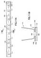
- FIG. 10Ais a top view of a light emitting diode (LED) lighting strip for use in the lighting fixture of FIGS. 4A-4B .
- LEDlight emitting diode
- FIG. 10Bis a cross-sectional view of the light emitting diode (LED) lighting strip of FIG. 10A taken along line 10 B- 10 B in FIG. 10A .
- LEDlight emitting diode
- FIG. 10Cis a cross-sectional view of the light emitting diode (LED) lighting strip of FIG. 10A taken along line 10 C- 10 C in FIG. 10A .
- LEDlight emitting diode
- FIG. 11Ais a top view of another embodiment of a light emitting diode (LED) lighting strip for use in the lighting fixture of FIGS. 4A-4B .
- LEDlight emitting diode
- FIG. 11Bis a cross-sectional view of the light emitting diode (LED) lighting strip of FIG. 11A taken along line 11 B- 11 B in FIG. 11A .
- LEDlight emitting diode
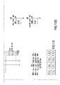
- FIG. 12is a schematic diagram of an exemplary embodiment of a driver circuit for use with the lighting fixture of FIGS. 4A-4B .
- FIGS. 13A-13Dare schematic diagrams of an exemplary computer circuit for use with the lighting fixture of FIGS. 4A-4B .
- FIG. 14is an exemplary flow diagram illustrating a possible control sequence for controlling operation of the lighting fixture of FIGS. 4A-4B .
- FIG. 15is a side perspective view of the lighting fixture FIGS. 4A-4B used as a streetlight.
- FIG. 16is cross-sectional view of the lighting emitting diode (LED) lighting strip adapted for use with the lighting fixture of FIGS. 4A-4B illustrating details of a reflector associated with the lighting strip.
- LEDlighting emitting diode
- FIG. 17is a cross-sectional view of another embodiment of the lighting emitting diode (LED) lighting strip adapted for use with the lighting fixture of FIGS. 4A-4B and comprising an alternative reflector.
- LEDlighting emitting diode
- FIG. 18is a top view of a blank used to manufacture the reflector of FIG. 17 .
- FIG. 19is a cross-sectional view of additional embodiment of the lighting emitting diode (LED) lighting strip adapted for use with the lighting fixture of FIGS. 4A-4B and comprising an additional embodiment of the reflector.
- LEDlighting emitting diode
- FIG. 20is a cross-sectional view of a further embodiment of the lighting emitting diode (LED) lighting strip adapted for use with the lighting fixture of FIGS. 4A-4B and comprising a further embodiment of the reflector.
- LEDlighting emitting diode
- FIG. 21is a top view of a blank used to manufacture the reflector of FIG. 20 .
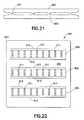
- FIG. 22is a front view of a lighting fixture in accordance with an embodiment adapted for use as an office lighting fixture.
- FIG. 23is a rear view of the office lighting fixture of FIG. 22 .
- FIG. 24is a side view of the office lighting fixture of FIG. 22 .
- FIG. 25is a cross-sectional view of a reflector adapted for used with a light emitting diode (LED) lighting strip used in lighting fixture of FIG. 22 .
- LEDlight emitting diode
- an embodiment of the present inventioninvolves a lighting arrangement incorporating one or more lighting strips comprising a plurality of light emitting diodes LEDs to provide a light emitting sub-assembly or device.
- a lighting fixturemay be provided that incorporates the LED lighting strips and desirably utilizes a shell or housing assembly of the lighting fixture as an integrated heat transfer device, often described herein as a thermal radiator, thereby effectively dissipating any heat created by the LEDs so as to prevent heat buildup within the lighting fixture and, thereby, permitting the LEDs to operate more efficiently for a longer life span.
- Additional embodimentsare directed to amplifying reflectors that may be associated with the lighting strips so that light produced by the plurality of light emitting diodes (LEDs) may be amplified and formed into a uniform beam which may be a focused beam useful, for example, as a spotlight, or a diffused beam useful, for example, as an overhead streetlight or possibly as an overhead office light.
- the combination of reflectors for amplifying or intensifying the light and the heat dissipation provided through the thermal radiation properties of the housingprovides for a lighting fixture adapted to provide effective light output for use as a street light, while not overheating and reducing the life span or safety of the street light.
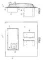
- Lighting fixture 1generally includes a housing 2 comprising a base plate 3 having a front side 5 and a rear side 7 .
- Base plate 3includes at least one and, preferably, a plurality of light emitting sub-assemblies 4 , also referred to herein as a lighting arrangement, particularly an LED lighting arrangement.
- Each light emitting sub-assembly 4is comprised of a lighting strip 9 , each including one or more surface-mounted LEDs 11 mounted thereto, and each light emitting sub-assembly may further include a reflector 13 mounted in a manner extending away from the lighting strip 9 , as will be described in more detail herein.
- Lighting strips 9are mounted to front side 5 of base plate 3 .
- Lighting strips 9may be mounted directly on front side 5 of base plate 3 , or may be mounted to a separate u-shaped channel or mounting stage that is directly mounted to base plate 3 , as described in more detail in connection with the embodiment of FIGS. 4-7 .
- Each lighting strip 9includes a plurality of surface-mount LEDs 11 mounted thereto, and may be constructed from any suitable material for mounting LEDs and associated circuitry, and is desirably constructed from aluminum.
- Base plate 3 and the base of lighting strip 9may be constructed from any suitable material adapted for radiating and transferring thermal energy.
- base plate 3 and lighting strip 9are constructed of aluminum or an aluminum alloy, such as aluminum alloy 1100 or aluminum alloy 3003 and, in particular, aluminum alloys subjected to an anodizing treatment.
- Lighting strip 9may have an exemplary overall thickness of about 1 ⁇ 8 inch thick, and base plate 3 may have an exemplary thickness about 1 ⁇ 8 to 1 ⁇ 4 inch thick.
- Base plate 3may also be formed in a representative iconic shape, such as a football, baseball glove, hockey stick, and the like to provide a decorative beam of light.
- LEDs 11are desirably high-power LEDs such as the LUXEON® REBEL manufactured by Phillips Lumileds Lighting Company or the CREE® XLAMP® XR-E LED manufactured by Cree, Inc.
- plasma emitter bulbsmay be used instead of LEDs 11 .
- Plasma emitter bulbsare typically the size of a dime. Each bulb is filled with a gas and metal halide materials. In operation, an electric field is applied to the bulb, which ionizes the gas molecules to create a gas plasma. The metal halides then completely join the gas plasma which emits a powerful white light.
- Such plasma emitter bulbsare currently manufactured by Luxim® Corporation.
- lighting fixture 1also includes a transparent cover 6 coupled to front side 5 of base plate 3 .
- Cover 6may be constructed of any suitable transparent material for passing light emitted by LEDs 11 therethrough, and is desirably selected from a polymeric material such as acrylic, ballistic acrylic, thermoplastic, polycarbonate, and the like.
- a polymeric materialsuch as acrylic, ballistic acrylic, thermoplastic, polycarbonate, and the like.
- One particularly suitable materialis LEXAN.
- the material forming cover 6is desirably shatterproof and otherwise weatherproof so as to prevent damage when exposed to the exterior environment.
- Transparent cover 6may be coupled to base plate 3 using any suitable fastening mechanism, such as using bolts 8 , so long as a generally airtight seal is maintained about the perimeter of housing 2 , thereby maintaining the interior portion of lighting fixture 1 as a sealed internal environment.
- a mounting bracket in the form of mounting member 10is coupled to rear side 7 of base plate 3 for mounting of lighting fixture 1 to an appropriate surface.
- Mounting member 10may comprise any general form for mounting to a particular surface, such as a plurality of mounting holes 12 for receiving a fastening member (not shown) which allows the lighting fixture 1 to be adjustably mounted to a pole.
- lighting fixture 1is configured to be mounted at a height sufficient to provide adequate lighting to a street or surface below. For instance, if lighting fixture 1 is mounted on a pole at a height of 30 feet above a street, lighting fixture 1 provides a lighting pattern that extends about 50 feet from the base of the pole and about 65 feet on either side of the pole.
- Each sub-assembly 4further includes a reflector 13 mounted so as to extend from the front side 5 of base plate 3 such that side walls 41 of reflector 13 extend at an angle from each of lighting strips 9 .
- Each reflector 13desirably includes a base portion (discussed in more detail herein) with a pair of side walls 41 extending from opposite sides thereof at an angle. Desirably, side walls 41 are integral with the base portion of reflector 13 .
- Reflector 13may be constructed of any reflective material, and may include a protective polymer coating thereon. Desirably, the material forming each reflector 13 has a reflectivity that is on the order of 95% to 98% reflective. Additionally, the polymer coating prevents corrosion on reflector 13 .
- An exemplary reflective materialis silver-coated aluminum, which is not to be construed as limiting, and any highly-reflective material may be used to construct the reflector assemblies.
- lighting fixture 1further includes a power supply and control circuitry (not shown) positioned within a rear housing 17 mounted on rear side 7 of base plate 3 .
- the power supply and control circuitryare electrically coupled to the plurality of LEDs 11 to provide effective lighting control, as described in more detail with respect to the embodiment of FIGS. 4-7 .
- Housing 17may also include a window 19 with a light detector in the form of a photoelectric eye 21 positioned thereunder.
- an acrylic rod or fiber optic array(not shown) may be positioned between window 19 and photoelectric eye 21 .
- photoelectric eye 21provides electronic signal(s) to the control circuitry which causes LEDs 11 to turn on when surrounding ambient light has dropped below a predetermined level as will be described hereinafter.
- An LED lightmay also be mounted on rear side 7 of base plate 3 and be coupled to the power supply and control circuitry for when, for example, utility workers are working on the pole where light fixture 1 is mounted. Such a separate, rear-mounted LED provides utility workers with appropriate lighting above lighting fixture 1 .
- This additional LED lightmay be turned on manually through the use of a magnetic switch, by an infrared sensor or by an ultrasonic sensor, as examples.
- Lighting fixture 101generally includes a housing 102 defined by a base plate 103 having a front side 105 forming a generally interior housing surface and a rear side 107 forming a generally outer housing surface for the lighting fixture.
- Lighting fixture 101includes at least one and, preferably, a plurality of light emitting sub-assemblies 104 , again also referred to herein as a lighting arrangement, particularly an LED lighting arrangement.
- Each light emitting sub-assembly 104includes a lighting strip 109 comprised of one or more surface-mounted LEDs 111 mounted to a circuit board substrate or base member 142 and each light emitting sub-assembly 104 may further include a reflector 141 mounted in a manner extending away from the lighting strip 109 , as will be described in more detail herein.
- Each lighting strip 109is mounted either directly or indirectly to base plate 103 in a manner permitting effective and efficient heat transfer between the LEDs 111 mounted to base member 142 and base plate 103 , as will be described in further detail herein.
- the LEDs 111may be mounted in a linear row or arrangement so that reflector 141 may effectively reflect light emitted by the LEDs 111 , amplify this light and direct the light in a manner effective for the intended purpose of the lighting fixture 101 , for example, as use as streetlight in the instant example or for other applications such as a spotlight, office overhead light, and other applications.
- the reflector 141may be configured to reflect and amplify the light from the LEDs 111 to achieve the light characteristics that are desired for the lighting fixture 101 .
- each lighting strip 109includes a plurality of linearly-arranged, surface-mount LEDs 111 mounted to base member 142 .
- Base member 142is desirably constructed, at least in part, of a similar material as base plate 103 , such as aluminum or aluminum alloy, preferably an anodized aluminum alloy.
- each lighting strip 109includes eight linearly-arranged LEDs 111 mounted to base member 142 .
- LEDs 111may be mounted to each lighting strip 109 .
- LEDs 111are desirably high-power LEDs such as the LUXEON® REBEL manufactured by Phillips Lumileds Lighting Company or the CREE® XLAMP® XR-E LED manufactured by Cree, Inc.
- plasma emitter bulbsmay be used instead of LEDs 111 . Such plasma emitter bulbs are currently manufactured by Luxim® Corporation, as noted previously.
- Base plate 103along with transparent cover 106 essentially forms the complete housing 102 of lighting fixture 101 .
- Base plate 103is typically constructed of a suitable material to structurally support lighting fixture 101 and to provide effective protection for the components and circuitry within lighting fixture 101 .
- base plate 103serves at least another purpose in that it also acts as a material for effectively and efficiently transferring thermal energy from LEDs 111 to dissipate heat therefrom, as will be further detailed herein.
- the interaction of base plate 103 and base member 142 effectively and efficiently conducts heat away from LEDs 111 and base plate 103is desirably adapted to transfer the heat energy to the ambient environment using any one or more of conductive, convective, and radiation heat transfer modes to the ambient environment.
- base plate 103may be constructed from any structurally supportive material that is adapted for transferring thermal energy.
- Base plate 103is desirably constructed of aluminum or an aluminum alloy, such as aluminum alloy 1100 or aluminum alloy 3003 and, in particular, aluminum alloys subjected to an anodizing treatment.
- Base plate 103may have an exemplary thickness about 1 ⁇ 8 to 1 ⁇ 4 inch thick.
- the base plate 103is provided with a heat-transferring surface texture, typically a non-uniform or non-smooth, somewhat roughened surface texture that increases the ability of the base plate 103 to transfer heat energy to the ambient environment and, accordingly, the anodizing process enhances the heat dissipating properties of base plate 103 , thereby allowing it to function as a particularly effective and efficient heat transfer device or mechanism, also termed herein as a “thermal radiator”.
- a heat-transferring surface texturetypically a non-uniform or non-smooth, somewhat roughened surface texture that increases the ability of the base plate 103 to transfer heat energy to the ambient environment and, accordingly, the anodizing process enhances the heat dissipating properties of base plate 103 , thereby allowing it to function as a particularly effective and efficient heat transfer device or mechanism, also termed herein as a “thermal radiator”.
- base plate 103may further include a plurality of thermal radiating fins 114 on rear side 107 to provide additional surface area for convective heat transfer and dissipation to the ambient environment, such that the LEDs 111 stay cool regardless of the outdoor temperature. Additionally, base plate 103 has an outer peripheral edge 112 that is curved away from a body of the base plate 103 at an angle of approximately 90°.
- lighting fixture 101includes a transparent cover 106 .
- Transparent cover 106may be manufactured from any suitable material such as, but not limited to, a polymeric material, such as acrylic, ballistic acrylic, thermoplastic, polycarbonate, and the like. Cover 106 is coupled with base plate 103 using any suitable mechanical fastening arrangement, so long as a generally airtight seal is maintained about the perimeter of housing 102 , thereby maintaining the interior portion of lighting fixture 101 as a sealed interior environment.
- transparent cover 106may be fitted such that an outer edge 108 is positioned adjacent to outer peripheral edge 112 of base plate 103 .
- a gasket 113is positioned between outer edge 108 of transparent cover 106 and outer peripheral edge 112 of base plate 103 to provide a generally fluid-tight seal therebetween.
- Transparent cover 106may also include at least one protective vent 118 .
- Protective vent 118provides an effective barrier against harsh weather conditions (e.g., rain, snow, high winds), while allowing water vapor to exit effectively from within transparent cover 106 , thereby reducing the likelihood of condensation accumulating beneath transparent cover 106 .
- Protective vent 118equalizes pressure between the transparent cover and the ambient environment and is desirably able to vent moisture that becomes trapped within the interior enclosure of housing 102 generally defined by transparent cover 106 and base plate 103 , while allowing only dry air to enter into the enclosure created by transparent cover 106 .
- An example of such a protective vent 118is the GORETM Protective Vent manufactured by W.L. Gore & Associates, Inc.
- a suitable clamp arrangementsuch as a plurality of spring clips 115 , is positioned over outer edge 108 of transparent cover 106 and outer peripheral edge 111 of base plate 103 to fixedly hold transparent cover 106 to base plate 103 .
- Spring clips 115are desirably formed with securing structure 117 , such as teeth, positioned on an inner surface thereof.
- Spring clips 115are desirably adapted to allow for transparent cover 106 to be quickly and easily removed.
- a special toolmay be provided for use with spring clips 115 to open and remove spring clips 115 from association with transparent cover 106 and base plate 103 .
- Pole mounting member 119includes a first clamp member 121 and a second clamp member 123 .
- First clamp memberdefines a first arcuate surface 125 and second clamp member defines a second, opposing arcuate surface 127 .
- First arcuate surface 125 and second arcuate surface 127are configured to face one another and capture a pole (not shown) therebetween.
- First clamp member 121 and second clamp member 123desirably each have an inside surface having a waffle pattern thereon. This waffle-pattern grips the pole when it is positioned between first clamp member 121 and second clamp member 123 thereby preventing rotation of the lighting fixture 101 relative to the pole.
- First clamp member 121 and second clamp member 123each also define a pair of arcuate slots 133 , 135 . Arcuate slots 133 , 135 are configured to receive respective bars 137 .
- Mounting bars 137are designed to move within arcuate slots 133 , 135 to allow lighting fixture 101 to be angularly adjusted for use in directing light output from lighting fixture 101 .
- lighting fixture 101is mounted to an extension pole extending from an upstanding pole (such as a telephone-style pole) and it is desired that lighting fixture 101 be positioned with the transparent cover 106 thereof facing downward and generally parallel to the ground surface, thereby directing light output directly downwardly.
- the arrangement of mounting bars 137 and arcuate slots 133 , 135provide lighting fixture to be mounted in such a manner regardless of the angle that the extension pole extends from the upstanding pole, as will be appreciated by those skilled in the art. It is also contemplated that alternative mounting clamps may be utilized with the present lighting fixture, depending upon the particular installation application.
- lighting fixture 101includes a plurality of light emitting sub-assemblies 104 including LED lighting strips 109 on front side 105 of base plate 103 .
- Each lighting strip 109includes a plurality of surface-mount LEDs 111 mounted onto circuit board or base member 142 in electrical contact/connection therewith and a reflector 141 mounted thereto.
- reflector 141defines multiple facets formed therein that amplify the light provided by LEDs 111 as will be discussed in greater detail hereinafter. Such facts may be angled fog nations in the body of the reflector 141 but reflector 141 is not intended to be limited to such facets.
- Facetsshould be read broadly in connection with this disclosure as a formation(s) in the body of reflector 141 that amplify the light output of the LEDs 111 and direct the amplified and desirably uniform light outward from the light fixture 101 for any desirable application.
- Lighting fixtures 1 , 101 in accordance with this disclosureexhibit effective and efficient dissipation of the heat generated by LEDs 11 , 111 .
- this heat dissipationis accomplished utilizing the entire housing of the lighting fixture 1 , 101 as a heat transfer device which effectively transfers heat energy generated LEDs 1 , 111 to the external environment.
- base plate 103may be formed of specific materials having suitable heat transfer characteristics and this material may be anodized and coated to provide a surface texture on the base plate 103 having enhanced heat transferring properties.
- Heat-transfer fins 114are also provided on base plate 103 for improving heat transferring attributes of base plate 103 .
- a further aspect of the heat transferring ability of light fixture 101 in particularis the arrangement of LEDs 111 with circuit board base member 142 and the mounting of the base member 142 to the base plate 103 . As described next herein, this arrangement enhances the heat transfer from LEDs 111 to base plate 103 .
- each lighting strip 109includes a singular line of LEDs 111 mounted onto base member 142 .
- Base member 142is desirably constructed of the same material as base plate 103 .
- base member 142represents a circuit substrate for LEDs 111 , including a metallic base supporting substrate layer 142 a , such as anodized aluminum oxide, with a non-conductive layer 142 b on a surface thereof, such as a ceramic layer or enamel layer.
- Electronic circuitryis then printed onto the non-conductive layer 142 b , with a second non-conductive layer positioned over the circuitry.
- Such a configurationis generally known in the semi-conductor art and the illustration of metallic base supporting substrate layer 142 a and non-conductive layer 142 b is for explanatory purposes only. If desired, a fiberglass layer may also be provided between the circuitry and the second non-conductive layer.
- the LEDs 111are mounted to the surface of base member 142 in electrical contact with the circuitry therein, thereby forming each lighting strip 109 .
- Reflector 141is further mounted on the surface of base member 142 , with LEDs 111 extending through openings 144 through the base portion of reflector 141 .
- each reflector 141comprises opposed side walls defining facets, as mentioned previously; various embodiments of reflector 141 are described herein but each such embodiment is generally in the form of an elongated channel structure having a base portion or member and side walls defining said facets.
- the base portion or memberis desirably positioned flush with the top surface of base member 142 of lighting strip 109 and is mounted thereon using suitable fastening means, such as an adhesive, bolts, rivets, and the like.
- reflector 141defines openings 144 through the base portion such that when reflector 141 is mounted to base member 142 , light from LEDs 111 can reflect off the interior surfaces of the side walls of the reflector 141 , as will be described in greater detail with reference to the reflector embodiments depicted in FIGS. 16-21 .
- Each lighting strip 109 with reflector 141 mounted theretothereby forms each light emitting sub-assembly 104 .
- Each lighting strip 109also includes an electrical connector 149 that allows the lighting strip 109 of the light emitting sub-assembly 104 to be operatively connected to a driver circuit 150 .
- driver circuit 150divides the power output from a power supply 151 equally among the plurality of lighting strips 109 , such as four lighting strips 109 in the instant embodiment, with little to no variation in amperage between the respective lighting strips 109 . This division is effective in extending the lifespan of LEDs 111 .
- base plate 103 of entire housing 102forms a mechanism for dissipating thermal energy to the ambient environment, essentially creating a heat transfer mechanism for dissipating heat generated by the LEDs 111 in each lighting strip 109 .
- An aspect of the mounting of LEDs 111 on lighting strip 109is that there is significant physical contact between the bottom surface of lighting strip 109 and base plate 103 which provides robust heat transfer between the lighting strip 109 and base plate 103 and heat produced the LEDs 111 on the lighting strip 109 is effectively conducted to base plate 103 for transfer to the ambient environment.
- the housing 102 of lighting fixture 101acts as a thermal radiating mechanism or device in accordance with this disclosure.
- direct physical contact between the portion of lighting strip 109 and base plate 103generally comprises base member 142 being in significant surface area contact with base plate 103 such that any gap between the inter-contacting surfaces is less than one hundredth of an inch (0.01 inches), and preferably less than about one thousandth of an inch (0.001 inches).
- This inter-contacting surface engagementis effective in achieving the desired heat transfer from the respective lighting strips 109 to base plate 103 .
- this disclosurecontemplates the foregoing-described engagement of each lighting strip 109 with base plate 103 to achieve the desired cooling of LEDs 111 .
- base member 142 for each lighting strip 109may be mounted directly to base plate 103 or indirectly to base plate 103 by some intervening structure. Any such intervening structure is desirably connected to base plate 103 so as not to inhibit substantially the heat transfer between base member 142 and base plate 103 of housing 102 .
- conventional fastening methodsmay be used to mount the respective lighting strips 109 to the front side 105 of base plate 103 .
- Such conventional fastening methodsinclude, for example, using mechanical fasteners such as screws, bolts or rivets, conductive adhesives, welding, or other known attachment means.
- portions of light emitting sub-assembly 104may be interconnected using mechanical fasteners that extend below the bottom surface of the sub-assembly 104 , such that the bottom surface of the thus-prepared light emitting sub-assembly 104 includes a discontinuous surface.
- reflector 141may be attached to lighting strip 109 through a rivet, which extends through respective holes in base member 142 of lighting strip 109 below the bottom thereof creating a protrusion, thereby preventing the bottom surface of lighting strip 109 from providing a smooth surface for direct contact with a separate surface, such as base plate 103 .
- a separate mounting bracketmay be used to support the lighting strips 109 on base plate 103 so as to maintain effective contact for heat transfer, and such intervening structure should not inhibit heat transfer from the lighting strips 109 to the base plate 103 in accordance with this disclosure. For example, as depicted in FIGS.
- lighting strips 109may be mounted to a separate mounting stage 148 , such as in the form of a u-shaped channel, which is directly mounted to base plate 103 .
- base plate 103may include a series of mounting stages 148 as a u-shaped channel that is unitarily formed with base plate 103 or otherwise connected thereto, such as through welding, for providing effective heat transfer therebetween.
- Mounting stages 148desirably conduct heat energy effectively and efficiently from lighting strips 109 to the main body of base plate 103 .
- each lighting strip 109may further be mounted onto a separate mounting member 143 .
- each light emitting sub-assembly 104may further include a mounting member 143 acting as a support plate for mounting base member 142 of lighting strip 109 (including electrically connected LEDs 111 ) thereto.
- Mounting member 143may be formed of any suitable material adapted for providing structural support to lighting strip 109 , and is desirably formed of the same material as base member 142 of lighting strip 109 , such as an anodized aluminum alloy, having the desirable heat transfer characteristics described previously.
- Mounting member 143generally has the same thickness as base member 142 , and is desirably of the same general length as base member 142 and desirably has a width greater than 1.5 times that of base member 142 and, more desirably, a width equal to or greater than two times that of base member 142 . In this manner, any protrusion formed from a fastening member extending through base member 142 will be offset from the attachment between mounting member 143 and stage 148 .
- light emitting sub-assembly 104may be effectively attached to base plate 103 via stage 148 with substantially the entire bottom surface of lighting strip 109 contacting mounting member 143 , and with mounting member 143 effectively contacting the entire upper surface of stage 148 .
- stage 148provides a mechanism for offset attachment of light emitting sub-assembly 104 so as to provide for sufficient contact between mounting member 143 and the upper surface of stage 148 for effect thermal transfer.
- stage 148can further provide a mechanism for additional surface area for heat transfer so as to further dissipate heat generated by LEDs 111 through mounting member 143 .
- mounting member 143(including lighting strip 109 attached thereto) may be connected to stage 148 in any known manner.
- mounting member 143defines a plurality of spaced grooves 145 formed along one longitudinal end thereof. Each of the grooves 145 is configured to receive a fastening member 147 to mount lighting strip 109 to stage 148 and, thereby, to the front side 105 of base plate 103 .
- a plurality of fastening memberscan be used to mount lighting strip 109 , thereby ensuring proper contact between the bottom surface area of mounting member 143 and stage 148 to provide effective heat transfer therebetween, which is effectively accomplished by limiting the gap between the bottom surface of mounting member 143 and the top surface of stage 148 to less than about 0.01 inches.
- each of the lighting strips 109is mounted to an individual stages 148 provided on the front side 105 of base plate 103 .
- the individual lighting strips 109can easily be mounted or removed from base plate 103 expediting replacement of a defective and/or damaged lighting strip 109 .
- the foregoing mounting configurationallows for a quick and easy change of LED lighting strips 109 , for example, if one of LED lighting strips 109 is damaged or defective. It is known that in conventional incandescent lighting fixtures, replacement of a worn out or defective lamp involves mere replacement of the bulb unit.
- LED lightsrepresent circuit chips that are electrically mounted onto a circuit board. Accordingly, replacement of a worn or defective LED chip involves replacement of the entire LED board.
- the attachment and mounting configuration contemplated through the various embodiments in this disclosureprovides a mechanism for quick and easy replacement of one or more LED lighting strips 109 , without requiring significant modification or rebuilding of the lighting fixture. Moreover, by providing multiple strips of LEDs in a single fixture, if one LED light or strip fails, the fixture will still be able to provide light output through the remaining functional lighting strips, albeit at a reduced level, until such time that the malfunctioning lighting strip or individual lighting assembly can be replaced.
- transparent cover 106is removed by removal of clamps 115 .
- Fastening members 147 positioned in grooves 145can then be loosened and removed using an appropriate tool.
- the defective or damaged LED lighting strip 109is removed from front side 105 of base plate 103 .
- electrical connector 149is disconnected from driver circuit 150 .
- a new LED lighting strip 109is supplanted for the defective or damaged LED lighting strip 109 .
- Transparent cover 106is then reassembled to base plate 103 .
- lighting strips 109may be configured to be mounted to stages 148 in a slightly different manner.
- Lighting strip 109 of FIGS. 11A-11Bis identical to that disclosed in previous embodiments, with the exception that “keyhole” shaped openings 156 extend through the surface of lighting strip 109 .
- Such keyhole openings 156provide a mechanism for attachment of lighting strip 109 to base plate 103 of housing 102 .
- mechanical fastenerssuch as screws, may be inserted into keyhole openings 156 and extend through corresponding openings 158 in underlying mounting member 143 to engage a stage 148 on base plate 103 .
- the mechanical engagementis desirably sufficient to enable effective and efficient heat transfer between the lighting strip 109 and base plate 103 .
- the keyhole openings 156allow lateral adjustment of lighting strip 109 relative to mounting member 143 to allow for proper attachment of a reflector 141 to the lighting strip 109 .
- a plurality of spaced fastenersare desirably used so as provide for effective surface contacting engagement between the bottom surface of lighting strip 109 and the top surface of stage 148 on base plate 103 for effective heat transfer therebetween, as discussed previously. It will be clear that the use of individual stages 148 for mounting the respective lighting strips 109 to base plate 103 may be eliminated such that the lighting strips 109 are mounted directly to base plate 103 .
- lighting fixture 101includes a power supply 151 , driver circuit 150 and computer circuit 160 .
- Power supply 151is desirably positioned within a housing 153 mounted on rear side 107 of base plate 103 .
- Driver circuit 150 and computer circuit 160are desirably mounted on front side 105 of base plate 103 beneath transparent cover 106 , thereby providing effective protection from the environment.
- Power supply 151is electrically coupled to a control board in the form of computer circuit 160 via a wire 155 extending through base plate 103 .
- Computer circuit 160is, in turn, coupled to a driver circuit board 150 .
- Driver circuit 150is electrically coupled to each lighting strip 109 via individual electrical connectors 149 .
- Driver circuit 150divides the power output from a power supply 151 equally among the four lighting strips 109 in the present embodiment.
- Driver circuit 150is electrically coupled to and controlled by computer circuit 160 to control operation of the individual lighting strips 109 .
- Each individual LED 111is electrically connected in series on each respective lighting strip 109 . Moreover, each respective lighting strip is connected in parallel to driver circuit 150 . Such an arrangement provides the driver circuit 150 with the ability to maintain the amperage constant even in the event that one or more LEDs 111 in any of the respective lighting strips 109 should fail. Such an arrangement also prevents an overload of power to any of the lighting strips 109 or other LEDs 111 thereon in the event of such a failure of one or more LEDs, thereby preventing premature burn out and failure of the remaining working LEDs, such as to prior to replacement of and individual lighting strip 109 .
- a light detectoris desirably provided in association with the light fixture 101 .
- the light detectorcomprises a photoelectric eye 170 that is mounted on housing 153 of power supply 151 and is electrically coupled to computer circuit 160 .
- Photoelectric eye 170is provided to turn on the LEDs 111 when surrounding ambient light has dropped below a predetermined level as will be described hereinafter.
- An exemplary embodiment of computer circuit 160is illustrated in FIG. 13 .
- Computer circuit 160utilizes a microcontroller chip 1300 as the primary means for controlling the light output by lighting fixture 101 . However, this is not to be construed as limiting as the use of other circuitry configurations, microprocessors, and microcontrollers may be substituted.
- driver circuit 150is illustrated in FIG. 12 .
- computer circuit 160is provided for automated control of various functions of lighting fixture 101 .
- computer circuit 160may include circuitry for controlling a remote camera (not shown) that may be provided with lighting fixture 101 .
- computer circuit 160may include circuitry for interaction with a separate wireless device that is adapted for programming the control board for operation of the lighting fixture.
- computer circuit 160may include circuitry to communicate with a separate remote control device via two-way radio-frequency (RF) so as to program the lighting fixture 101 .
- RFradio-frequency
- Other communication vehicles for communication with computer circuit 160such as via infrared (IR) light, are intended to be encompassed by this disclosure.
- lighting fixture 101may include a solar-power capability for powering computer circuit 160 and lighting strips 109 .
- computer circuit 160works in conjunction with photoelectric eye 170 to automatically turn exemplary street lighting fixture 101 on and off based on ambient light conditions, and to adjust the lighting at predetermined time periods.
- FIG. 14the on-off and power adjustment features of lighting fixture 101 are schematically illustrated.
- poweris supplied to computer circuit 160 thereby initializing the computer circuit 160 at block 1400 .
- photoelectric eye 170looks for diminished ambient light, signaling, for example, the arrival of dusk, if the lighting fixture 101 is intended for use as a street lamp, and this information is provided as an input to computer circuit 160 .
- Once sufficiently diminished light (such as at dusk), as detected by photoelectric eye 170is determined by computer circuit 160 , the computer circuit 160 turns lighting fixture 101 on at full power at block 1420 .
- the power of the light outputmay be reduced by a predetermined amount for further energy conservation, for example, in the middle of the night when fewer people are likely to be in the vicinity of street lighting fixture 101 .
- a counter in the computer circuit 160may begin counting.
- the computer circuit 160may reduce power to the LEDs 111 to save power.
- computer circuit 160may be programmed to turn on the lighting fixture 109 at a scheduled time, such as at 6:00 PM.
- the power reduction to light output ratiois not a 1:1 ratio, such that, for example, a 50% reduction in power output continues to provide for an overall light output of the lighting fixture of about 75% of the normal light output, thereby resulting in only about a 25% reduction in light output with a 50% reduction in power.
- photoelectric eye 170looks for increased ambient light signaling, for example, the arrival of dawn. Once sufficient ambient light (such as at dawn) is detected by photoelectric eye 170 at block 1460 , LEDs 111 of lighting fixture 101 are turned off by the computer circuit 160 and the process returns to block 1410 .
- LEDs 111 of lighting fixture 101are turned off by the computer circuit 160 and the process returns to block 1410 .
- this processextends the life of LEDs 111 .
- the controller of computer circuit 160also provides a safety start feature.
- the safety start featureallows the LEDs 111 to turn on slowly over a predetermined time interval. The LEDs 111 start at an off position. Once the computer circuit 160 sends a signal to turn on the LEDs 111 , the LEDs are turned on at a low power and the power is gradually increased over a predetermined period, such as a 2 to 3 second interval, until full power is reached.
- the purpose of this safety start featureis to protect the human eye from sudden brightness created when the LEDs 111 are turned on at full power. This feature also prevents “welder's flash” when the LEDs 111 are turned on.
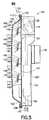
- Lighting fixture 101is configured to be mounted by pole mounting member 119 to a pole 181 at a height sufficient to provide adequate lighting to a street 183 or surface below. For instance, if lighting fixture 101 is mounted on a pole at a height of about 30 feet above a street, lighting fixture 101 provides a lighting pattern that extends about 50 feet from the base of the pole and about 65 feet on either side of the pole. It is further contemplated that lighting fixture 101 can be adapted for other attachment mechanisms, such as a rectangular pole, a surface mount, etc.
- the inventorshave determined that for providing effective light output at a conventional distance for a streetlight (such as about 25-40 feet from the ground surface), four lighting strips 109 including 8 separate LED chips mounted thereon is particularly useful, with each LED chip rated at 80-120 lumens.
- the light output with such an arrangement having individual LED chips rated at 107 lumenseach represents about 2.5 foot-candles at a distance of 32 feet without any reflectors attached to the lighting strips.
- a similar arrangement with individual LED chips rated at 107 lumenseach represents about 6.7 foot-candles at a distance of 32 feet. Accordingly, the reflector arrangement significantly amplifies and intensifies the light output for the lighting fixture 101 .
- Lighting fixture 101may be assembled by the following general and non-limiting procedure. First, driver circuit 150 and control circuit 160 are mounted to base plate 103 and electrically interconnected. Then, lighting strips 109 are mounted to base plate 103 via the individual mounting members 143 and/or stages 148 and using suitable fastening means such as mechanical fasteners and the like. Next, each lighting strip 109 is electrically coupled to driver circuit 150 by individual electrical connectors 149 . Next, individual reflectors 141 are mounted onto lighting strips 109 as discussed hereinafter with reference to FIG. 16 . Transparent cover 106 may then be positioned over base plate 103 and secured thereto with spring clips 115 .
- Pole mounting member 119is mounted to rear side 107 of base plate 103 , and is adapted to cooperate with pole 181 as shown in FIG. 15 .
- Power supply 151is installed within housing 153 and is electrically connected to control circuit 160 through base plate 103 , and light detector 170 is attached to housing 153 and electrically connected to control circuit 160 .
- the reflector assemblyincludes a base member 184 and a pair of desirably integral side walls 185 extend from opposite sides of the base member 184 at an angle.
- Each LED 111includes a light emitting portion 187 .
- Reflector assembly 141is mounted to lighting strip 109 such that a bottom edge of each side wall 185 extends from a bottom portion of light emitting portion 187 of LED 111 .
- Each side wall 185 of reflector assembly 141includes a first facet or first portion 186 defining a first angle ⁇ with the base portion 184 of reflector 141 adjacent the bottom portion of light emitting portion 187 of LED 111 , and a second facet or second portion 188 that defines a second angle (I) with first portion 186 .
- the combination of these anglescreates facets in side walls 185 , thereby creating a multi-faceted side wall which amplifies the light provided by LEDs 111 . It is contemplated that the multiple facets reflect the light that is output from the LEDs back toward other facets of the walls of reflector 141 , thereby amplifying the light.
- a multi-faceted reflectormay also include reflectors having a parabolic shape.
- the arrangement of reflector 141 extending from base member 184allows all of the light produced by LEDs 111 to be reflected and amplified by reflector 141 .
- the angles in side walls 185 of reflector 141 along with the arrangement of reflector 141 such that it extends from the bottom portion of light emitting portion 187 of LED 111allows lighting fixture 101 to produce useable light while using a small number of LEDs 111 (e.g., the exemplary embodiment illustrated in FIG. 4 has eight LEDs 111 per lighting strip 109 and four lighting strips 109 for a total of thirty-two LEDs 111 ).
- FIG. 17provides a cross-sectional view of a first reflector, generally denoted as reference numeral 200 that is also desirably used when lighting fixture 1 or lighting fixture 101 is used as a streetlight but provides a different effect from the previously discussed embodiment.
- Reflector 200includes a base portion or member 201 with a pair of integral side walls 203 extending from opposite sides thereof at an angle.
- Base member 201includes a plurality of holes 205 used to fasten reflector 200 to lighting strip 9 or lighting strip 109 using any suitable fastening means.
- Base member 201also defines a plurality of gaps or openings 207 formed therein.
- Base member 201 of reflector 200is mounted over one of the lighting strips 9 or lighting strips 109 such that surface-mount LEDs 11 or LEDs 111 positioned on lighting strips 9 or strips 109 extend through gaps 207 and side walls 203 of reflector 200 extend at an angle from lighting strip 9 or strip 109 .
- Each of side walls 203 of reflector 200has several angles therein as shown in FIG. 17 .
- Each side wall 203 of reflector 200includes a first portion 209 that extends from base member 201 at a first angle ⁇ of, for example, about 115° to about 130°, such as about 123°.
- Side walls 203further include a second portion 211 that defines a second angle ⁇ with the first portion 209 ; this angle is approximately between 160° to about 180°, such as about 170°.
- side walls 203in the present configuration, include a third portion 213 that defines a third angle ⁇ with the second portion 211 ; this angle is again about 160° to about 180°, such as about 170°.
- This configurationcreates an overall angle of about 40° between ends 215 of each of side walls 203 of reflector 200 .
- the combination of these anglescreates facets in the reflector which amplify the light provided by LEDs 11 or LEDs 111 .
- side walls 203 of reflector assemblies 200amplifies the light from each of the plurality of strips 9 or strips 109 of LEDs 11 or LEDs 111 and spreads the light into what appears to be a wash or bath of light.
- Reflector 200is desirably constructed from a sheet of silver-coated aluminum with a protective polymer coating. Such a material has a reflectivity that is from about 95% to 98% reflective. Additionally, the polymer coating prevents corrosion on reflector 200 .
- the use of silver-coated aluminum reflectorsis not to be construed as limiting as any highly-reflective material may be used to construct the reflector assemblies.
- Reflector blank 217is a flat sheet that that shaped to form side walls 203 extending from base member 201 , and a plurality of holes 205 and a plurality of gaps 207 are cut in the reflector blank 217 using, for example, a laser. Reflector blank 217 is then bent into the shape discussed hereinabove using a brake press.
- This reflector 300includes a base portion or member 301 with a pair of integral side walls 303 extending from opposite sides thereof at an angle. Each of side walls 303 of reflector 300 has several angles therein as shown in FIG. 19 .
- Each side wall 303 of reflector 300includes a first portion 305 that extends from lighting strip 9 or strip 109 at an initial or first angle ⁇ of, for example, about 115° to about 130°, such as about 121°.
- Side walls 305 of reflector 300further include a second portion 307 that defines a second angle ⁇ with the first portion 305 ; this angle is approximately between 160° to about 180°, such as about 170°. This configuration creates an overall angle of about 60° between ends 309 of each side wall 303 of reflector 300 .
- Reflector assemblies 300are constructed from silver-coated aluminum with a protective polymer coating as described previously.
- This reflector 400includes a base portion or member 401 with a pair of integral side walls 403 extending from opposite sides thereof at an angle. Each side wall 403 of reflector 400 has several angles therein as shown in FIG. 20 .
- Each side wall 403 of reflector 400includes a first portion 405 that extends from base member 401 at a first angle ⁇ of, for example, about 110° to about 120°, such as about 115°.
- Side walls 403further include a second portion 407 that defines a second angle ⁇ with the first portion 405 ; this angle is, for example, about 170° to about 180°, such as about 177°.
- Reflector assemblies 400are also constructed from silver-coated aluminum with a protective polymer coating in like manner to previous embodiments.
- FIGS. 17-21illustrate possible configurations of the reflector assemblies, this is not to be construed as limiting the present invention as other suitable configurations may be constructed.
- Various other types of reflectors for use in LED lighting fixtureshave been envisioned.
- the reflectorsmay be of a rounded-type with multiple facet angles.
- a lighting fixture 501for use as office lighting, includes a base plate 503 having a front side 505 and a rear side 507 defined by a periphery 512 .
- Three strips 509are mounted on front side 505 of base plate 503 .
- Each strip 509includes a plurality of surface-mount LEDs 511 mounted thereto.
- Base plate 503functions as a heat sink for LEDs 511 and is oversized compared to lighting strips 509 to ensure that LEDs 511 stay cool; base plate 503 has the same heat cooling attributes of base plate 103 discussed previously and the previous discussion of base plate 103 is equally applicable to base plate 503 .
- Base plate 503provides surface area for cooling LEDs 511 which extends LED life.
- Lighting fixture 500is typically intended for indoor use. Accordingly, a sealed cover is not required.
- a housing 521is mounted to front side 501 of base plate 503 , which also houses a power supply and driver circuitry and a lens cover (not shown). The housing itself is used for installing the fixture in office ceilings and the like.
- reflectors 513is mounted to front side 505 of base plate 503 such that side walls 517 extend from each of the lighting strips 509 .
- Each reflector 513includes a base portion or member 515 with a pair of integral side walls 517 extending from opposite sides thereof at an angle.
- Base member 515 of reflector 513is mounted on front side 505 of base plate 503 over one of the strips 509 such that surface-mount LEDs 511 positioned on strips 509 extend through gaps or openings formed in base 515 , and side walls 517 of reflector 513 extend at an angle from each of the lighting strips 519 .
- Each side wall 517 of reflector 513extends from base member 515 at an angle ⁇ of, for example, about 115°. This configuration creates an overall angle of about, for example, 90° between ends 519 of each side wall 517 of reflector 513 .
- Side walls 517 of reflector 513amplify the light provided by LEDs 511 .
- side walls 517 of reflector 513direct the light from each of the three strips 509 of LEDs 511 and focus the light into what appears to be a uniform beam of light.
- Reflectors 513are desirably constructed from silver-coated aluminum with a protective polymer coating in like manner to previous embodiments.
Landscapes
- Engineering & Computer Science (AREA)
- General Engineering & Computer Science (AREA)
- Computer Networks & Wireless Communication (AREA)
- Non-Portable Lighting Devices Or Systems Thereof (AREA)
- Arrangement Of Elements, Cooling, Sealing, Or The Like Of Lighting Devices (AREA)
Abstract
Description
Claims (37)
Priority Applications (4)
| Application Number | Priority Date | Filing Date | Title |
|---|---|---|---|
| US12/341,798US8322881B1 (en) | 2007-12-21 | 2008-12-22 | Lighting fixture |
| US13/692,402US9699854B2 (en) | 2007-12-21 | 2012-12-03 | Lighting fixture |
| US15/186,142US11959631B2 (en) | 2007-12-21 | 2016-06-17 | Lighting fixture |
| US18/604,477US20250102132A1 (en) | 2007-12-21 | 2024-03-13 | Lighting Fixture |
Applications Claiming Priority (4)
| Application Number | Priority Date | Filing Date | Title |
|---|---|---|---|
| US1571307P | 2007-12-21 | 2007-12-21 | |
| US9457108P | 2008-09-05 | 2008-09-05 | |
| US9455808P | 2008-09-05 | 2008-09-05 | |
| US12/341,798US8322881B1 (en) | 2007-12-21 | 2008-12-22 | Lighting fixture |
Related Child Applications (1)
| Application Number | Title | Priority Date | Filing Date |
|---|---|---|---|
| US13/692,402ContinuationUS9699854B2 (en) | 2007-12-21 | 2012-12-03 | Lighting fixture |
Publications (1)
| Publication Number | Publication Date |
|---|---|
| US8322881B1true US8322881B1 (en) | 2012-12-04 |
Family
ID=47226622
Family Applications (4)
| Application Number | Title | Priority Date | Filing Date |
|---|---|---|---|
| US12/341,798Active - Reinstated2031-04-13US8322881B1 (en) | 2007-12-21 | 2008-12-22 | Lighting fixture |
| US13/692,402ActiveUS9699854B2 (en) | 2007-12-21 | 2012-12-03 | Lighting fixture |
| US15/186,142Active2029-07-22US11959631B2 (en) | 2007-12-21 | 2016-06-17 | Lighting fixture |
| US18/604,477PendingUS20250102132A1 (en) | 2007-12-21 | 2024-03-13 | Lighting Fixture |
Family Applications After (3)
| Application Number | Title | Priority Date | Filing Date |
|---|---|---|---|
| US13/692,402ActiveUS9699854B2 (en) | 2007-12-21 | 2012-12-03 | Lighting fixture |
| US15/186,142Active2029-07-22US11959631B2 (en) | 2007-12-21 | 2016-06-17 | Lighting fixture |
| US18/604,477PendingUS20250102132A1 (en) | 2007-12-21 | 2024-03-13 | Lighting Fixture |
Country Status (1)
| Country | Link |
|---|---|
| US (4) | US8322881B1 (en) |
Cited By (37)
| Publication number | Priority date | Publication date | Assignee | Title |
|---|---|---|---|---|
| US20110273886A1 (en)* | 2010-05-07 | 2011-11-10 | Min-Hao Michael Lu | Luminaire having non-revealed area light sources |
| US20120002408A1 (en)* | 2010-07-01 | 2012-01-05 | Jan Flemming Samuel Lichten | Lighting fixture for a poultry house |
| US20130033889A1 (en)* | 2011-08-03 | 2013-02-07 | Li-Sheng Teng | Light guide decorative plate and touch light decorative plate |
| US20130039054A1 (en)* | 2011-08-09 | 2013-02-14 | Foxsemicon Integrated Technology, Inc. | Light-emitting diode lamp |
| US20130063934A1 (en)* | 2011-09-09 | 2013-03-14 | Llyod E. VERMELAND | Water resistant lighting fixture |
| US20130155675A1 (en)* | 2007-12-21 | 2013-06-20 | Appalachian Lighting Systems, Inc. | Lighting Fixture |
| US20130250562A1 (en)* | 2012-03-23 | 2013-09-26 | Toshiba Lighting & Technology Corporation | Wiring board device, luminaire, and manufacturing method of the wiring board device |
| US20140168991A1 (en)* | 2012-12-14 | 2014-06-19 | Jong-Chen KIM | Led lamp |
| US20140218913A1 (en)* | 2013-02-04 | 2014-08-07 | Galtronics Corporation Ltd. | Lighting device with integrated slot antenna |
| US9028096B2 (en)* | 2011-10-05 | 2015-05-12 | Dialight Corporation | Angled street light fixture |
| US9182096B2 (en)* | 2013-03-06 | 2015-11-10 | Cree, Inc. | Light fixture |
| RU2572092C2 (en)* | 2014-03-31 | 2015-12-27 | Общество с ограниченной ответственностью "СПЕКОМИКС-М" | Light-emitting diode lighting fixture |
| WO2016033320A1 (en)* | 2014-08-28 | 2016-03-03 | Cooper Technologies Company | Lighting fixture |
| US20160131350A1 (en)* | 2013-06-09 | 2016-05-12 | Sichuan Sunfor Light Co., Ltd. | Ultrathin led light engine |
| US20160178148A1 (en)* | 2013-08-26 | 2016-06-23 | Kmw Inc. | Led streetlamp |
| US20170051911A1 (en)* | 2014-04-29 | 2017-02-23 | Qingbo XIE | Waterproof led lamp and led lamp set |
| US10168023B1 (en)* | 2015-10-28 | 2019-01-01 | NLS Lighting, LLC | Reflector based illumination system |
| US10208907B2 (en)* | 2017-01-05 | 2019-02-19 | Lite-On Electronics (Guangzhou) Limited | Lighting device and reflective plate therefor for making the lighting device generate a predetermined light type |
| US20190137081A1 (en)* | 2012-05-08 | 2019-05-09 | Eaton Intelligent Power Limited | Systems, Methods, and Devices for Providing Rotatable Light Modules |
| US10323807B2 (en)* | 2015-08-20 | 2019-06-18 | Natalia Olegovna Sterkina | Method of generating a light output and an elongate cornice lamp for the implementation thereof |
| US10337693B1 (en) | 2017-02-10 | 2019-07-02 | Musco Corporation | Apparatus method, and system for cost-effective lighting system retrofits including LED luminaires |
| US10344948B1 (en) | 2017-02-10 | 2019-07-09 | Musco Corporation | Glare control, horizontal beam containment, and controls in cost-effective LED lighting system retrofits and other applications |
| US20200049324A1 (en)* | 2016-02-27 | 2020-02-13 | Sergiy Vasylyev | Method of making structurally reinforced illumination panels |
| US10681798B2 (en)* | 2015-09-30 | 2020-06-09 | Chiscan Holding, Llc | Devices for controlling non-thermal plasma emitters |
| US20200240600A1 (en)* | 2019-01-28 | 2020-07-30 | Shenzhen Fototech Photographic Equipment Co., Ltd | Curlable Lamp |
| US10741107B2 (en) | 2013-12-31 | 2020-08-11 | Ultravision Technologies, Llc | Modular display panel |
| US10891881B2 (en) | 2012-07-30 | 2021-01-12 | Ultravision Technologies, Llc | Lighting assembly with LEDs and optical elements |
| US11102877B2 (en)* | 2015-09-30 | 2021-08-24 | Chiscan Holdings, L.L.C. | Apparatus and methods for deactivating microorganisms with non-thermal plasma |
| US20220136687A1 (en)* | 2014-05-23 | 2022-05-05 | Hubbell Incorporated | Luminaire With Adjustable Lamp Modules |
| RU212090U1 (en)* | 2022-03-15 | 2022-07-06 | Публичное акционерное общество "Татнефть" имени В.Д. Шашина | Reflective screen |
| US20220221113A1 (en)* | 2019-05-13 | 2022-07-14 | Signify Holding B.V. | Led strip configurtions for large area round luminaires providing homogeneous lighting |
| USD964925S1 (en)* | 2019-08-20 | 2022-09-27 | Christopher McMurry | Charging base tray for flameless candles |
| US20230161127A1 (en)* | 2020-04-15 | 2023-05-25 | CommScope Connectivity Belgium BV | Device and method for sealing cables in telecommunications enclosures |
| USRE49637E1 (en) | 2008-04-04 | 2023-08-29 | Ideal Industries Lighting Llc | Systems and methods for high output, high color quality light |
| US12069793B2 (en) | 2020-04-09 | 2024-08-20 | Chiscan Holdings Pte. Ltd. | Treatment of infectious diseases using non-thermal plasma |
| CN119103515A (en)* | 2024-09-24 | 2024-12-10 | 深圳市奇异电气有限公司 | A light intensity adaptive clean lamp |
| US12372219B2 (en)* | 2014-05-30 | 2025-07-29 | Cree Lighting Usa Llc | LED luminaire with a cavity, finned interior, and a curved outer wall extending from a surface on which the light source is mounted |
Families Citing this family (7)
| Publication number | Priority date | Publication date | Assignee | Title |
|---|---|---|---|---|
| US20130175557A1 (en)* | 2011-09-02 | 2013-07-11 | The Procter & Gamble Company | Light emitting apparatus |
| TWI507126B (en)* | 2014-07-22 | 2015-11-11 | 玉晶光電股份有限公司 | Color adjustable fish lamp |
| ES2532051B1 (en)* | 2014-08-05 | 2016-01-04 | The Mad Pixel Factory S.L. | LED lighting device |
| US10612753B2 (en) | 2016-12-19 | 2020-04-07 | Current Lighting Solutions, Llc | Roadway fixture systems with integrated transceiving equipment |
| US11632848B2 (en) | 2019-06-03 | 2023-04-18 | Pauly Enterprises, LLC | Interconnected remote control lighting system |
| WO2023060273A1 (en)* | 2021-10-07 | 2023-04-13 | Far Uv Technologies, Inc. | Improved disinfection lighting systems and methods |
| WO2025166226A1 (en)* | 2024-02-02 | 2025-08-07 | Neotek, Inc. | Modular lighting fixture, system, and method for optimized plant growth in controlled environments |
Citations (70)
| Publication number | Priority date | Publication date | Assignee | Title |
|---|---|---|---|---|
| US5580156A (en)* | 1994-09-27 | 1996-12-03 | Koito Manufacturing Co., Ltd. | Marker apparatus |
| US5723868A (en)* | 1995-05-15 | 1998-03-03 | Welch Allyn, Inc. | Illuminating assembly for use with bar code readers |
| US6547416B2 (en) | 2000-12-21 | 2003-04-15 | Koninklijke Philips Electronics N.V. | Faceted multi-chip package to provide a beam of uniform white light from multiple monochrome LEDs |
| US6644841B2 (en) | 2002-03-01 | 2003-11-11 | Gelcore Llc | Light emitting diode reflector |
| US6648490B2 (en) | 2001-04-04 | 2003-11-18 | Erco Leuchten Gmbh | Reflector lighting fixture, especially for in-the-floor, in-the-wall or in-the-ceiling lighting |
| JP2004200102A (en) | 2002-12-20 | 2004-07-15 | Kankyo Shomei:Kk | Exterior illumination fixture by white light emitting diode |
| US6784357B1 (en) | 2002-02-07 | 2004-08-31 | Chao Hsiang Wang | Solar energy-operated street-lamp system |
| US20050111220A1 (en)* | 2003-11-21 | 2005-05-26 | Smith Todd J. | Composite reflecting surface for linear LED array |
| US6942361B1 (en) | 2002-12-19 | 2005-09-13 | Toshiji Kishimura | Light source for white color LED lighting and white color LED lighting device |
| US6971781B2 (en) | 2004-03-18 | 2005-12-06 | The Boeing Company | Remote source lighting |
| US20060056169A1 (en) | 2004-09-10 | 2006-03-16 | Pervaiz Lodhie | Light module using led clusters |
| US7067992B2 (en) | 2002-11-19 | 2006-06-27 | Denovo Lighting, Llc | Power controls for tube mounted LEDs with ballast |
| US7090370B2 (en) | 2001-06-08 | 2006-08-15 | Advanced Leds Limited | Exterior luminaire |
| US7114832B2 (en) | 2003-10-06 | 2006-10-03 | Illumination Management Solutions, Inc. | Method for shifting energy between beams when focusing or defocusing |
| US7119498B2 (en) | 2003-12-29 | 2006-10-10 | Texas Instruments Incorporated | Current control device for driving LED devices |
| US20060237738A1 (en) | 1997-11-19 | 2006-10-26 | Salam Hassan P A | LED lamps |
| US7172319B2 (en) | 2004-03-30 | 2007-02-06 | Illumination Management Solutions, Inc. | Apparatus and method for improved illumination area fill |
| US20070081339A1 (en) | 2005-10-07 | 2007-04-12 | Chung Huai-Ku | LED light source module with high efficiency heat dissipation |
| US7217009B2 (en) | 2003-09-29 | 2007-05-15 | Erco Leuchten Gmbh | Reflector-type light fixture |
| US7233115B2 (en) | 2004-03-15 | 2007-06-19 | Color Kinetics Incorporated | LED-based lighting network power control methods and apparatus |
| US20070153526A1 (en) | 2005-12-29 | 2007-07-05 | Lam Chiang Lim | LED housing |
| WO2007088665A1 (en) | 2006-01-31 | 2007-08-09 | Solar Wind Technology Inc. | Illumination device and illumination system |
| US20070195527A1 (en) | 2004-08-18 | 2007-08-23 | Remco Solid State Lighting Inc. | System and method for power control in a led luminaire |
| US20070201225A1 (en) | 2006-02-27 | 2007-08-30 | Illumination Management Systems | LED device for wide beam generation |
| US20070211463A1 (en) | 2000-12-20 | 2007-09-13 | Gestion Proche Inc. | Lighting device |
| US7275841B2 (en) | 2004-02-17 | 2007-10-02 | William M Kelly | Utility lamp |
| US20070230171A1 (en) | 2004-11-30 | 2007-10-04 | Toshio Hiratsuka | Illumination Unit and Illumination Apparatus |
| US7278761B2 (en) | 2005-10-06 | 2007-10-09 | Thermalking Technology International Co. | Heat dissipating pole illumination device |
| US20070247856A1 (en) | 2006-04-05 | 2007-10-25 | Wang Shih C | Lighting unit reflector |
| US20070263388A1 (en) | 2006-05-12 | 2007-11-15 | Industrial Technology Research Institute | Illumination device of flexible lighting angle |
| US20070285927A1 (en) | 2006-06-12 | 2007-12-13 | Grand Halo Technology Co., Ltd. | Light-emitting device |
| US20080002399A1 (en) | 2006-06-29 | 2008-01-03 | Russell George Villard | Modular led lighting fixture |
| CN101101096A (en) | 2007-07-27 | 2008-01-09 | 江苏伯乐达光电科技有限公司 | Highly effective slot-shaped reflective cover and its uses in LED road lamp |
| US20080055908A1 (en) | 2006-08-30 | 2008-03-06 | Chung Wu | Assembled structure of large-sized led lamp |
| US20080062689A1 (en) | 2006-09-12 | 2008-03-13 | Russell George Villard | Led lighting fixture |
| US20080062691A1 (en) | 2006-09-12 | 2008-03-13 | Russell George Villard | LED lighting fixture |
| US7347706B1 (en) | 2005-07-21 | 2008-03-25 | Leotek Electronics Corporation | Light emitting diode (LED) based street light and other lighting applications |
| US20080080162A1 (en) | 2006-09-30 | 2008-04-03 | Ruud Lighting, Inc. | LED Light Fixture with Uninterruptible Power Supply |
| US20080078524A1 (en) | 2006-09-30 | 2008-04-03 | Ruud Lighting, Inc. | Modular LED Units |
| US20080080196A1 (en) | 2006-09-30 | 2008-04-03 | Ruud Lighting, Inc. | LED Floodlight Fixture |
| US20080089069A1 (en) | 2006-10-11 | 2008-04-17 | Medendorp Nicholas W | Methods and Apparatus for Improved Heat Spreading in Solid State Lighting Systems |
| US20080089070A1 (en) | 2006-10-12 | 2008-04-17 | Chin-Wen Wang | Led lamp module with adjustable illuminating angle |
| US20080123340A1 (en) | 2006-11-27 | 2008-05-29 | Mcclellan Thomas | Light device having LED illumination and electronic circuit board in an enclosure |
| CN101191591A (en) | 2006-11-27 | 2008-06-04 | 杜忠良 | LED road lamp device |
| US20080136661A1 (en) | 2000-11-15 | 2008-06-12 | Federal Law Enforcement Development Service, Inc. | Led warning light and communication system |
| USD574549S1 (en) | 2007-05-04 | 2008-08-05 | Ruud Lighting, Inc. | Lighting fixture with top mount |
| USD574548S1 (en) | 2007-02-21 | 2008-08-05 | Ruud Lighting, Inc. | Ceiling lighting fixture |
| US7407307B2 (en) | 2005-08-30 | 2008-08-05 | Kabushikikaisha Mirai | Illuminating panel and illuminating device |
| US20080192476A1 (en) | 2005-08-30 | 2008-08-14 | Kabushikikaisha Mirai | Illuminating Device |
| US20080198572A1 (en) | 2007-02-21 | 2008-08-21 | Medendorp Nicholas W | LED lighting systems including luminescent layers on remote reflectors |
| USD576330S1 (en) | 2006-09-29 | 2008-09-02 | Ruud Lighting, Inc. | LED floodlight |
| USD576331S1 (en) | 2007-05-04 | 2008-09-02 | Ruud Lighting, Inc. | Curved pole with lighting fixture |
| USD576332S1 (en) | 2006-09-29 | 2008-09-02 | Ruud Lighting, Inc. | Wall-mount LED floodlight |
| US7420811B2 (en) | 2006-09-14 | 2008-09-02 | Tsung-Wen Chan | Heat sink structure for light-emitting diode based streetlamp |
| US20080212329A1 (en) | 2004-12-07 | 2008-09-04 | Louis Duguay | Assembly of Light Emitting Diodes for Lighting Applications |
| US20080219001A1 (en) | 2004-08-18 | 2008-09-11 | Ronald James Russell | Led Control Utilizing Dynamic Resistance of Leds |
| US20080231201A1 (en) | 2007-03-22 | 2008-09-25 | Robert Higley | Led lighting fixture |
| USD577847S1 (en) | 2007-11-07 | 2008-09-30 | Ruud Lighting, Inc. | Round floodlight fixture |
| US20080239750A1 (en) | 2007-03-28 | 2008-10-02 | Hon Hai Precision Industry Co., Ltd. | Led lamp assembly |
| US20080239722A1 (en) | 2007-04-02 | 2008-10-02 | Ruud Lighting, Inc. | Light-Directing LED Apparatus |
| US20080239751A1 (en) | 2007-03-27 | 2008-10-02 | Hon Hai Precision Industry Co., Ltd. | Led lamp assembly |
| US20080247170A1 (en) | 2005-03-03 | 2008-10-09 | Dialight Corporation | Led illumination device with a highly uniform illumination pattern |
| USD578695S1 (en) | 2008-03-10 | 2008-10-14 | Foxconn Technology Co., Ltd. | LED lamp assembly |
| USD578696S1 (en) | 2008-03-21 | 2008-10-14 | Foxconn Technology Co., Ltd. | LED lamp assembly |
| USD578698S1 (en) | 2008-03-24 | 2008-10-14 | Foxconn Technology Co., Ltd. | LED lamp |
| USD578697S1 (en) | 2008-03-21 | 2008-10-14 | Foxconn Technology Co., Ltd. | LED lamp |
| US20080253125A1 (en) | 2007-04-11 | 2008-10-16 | Shung-Wen Kang | High power LED lighting assembly incorporated with a heat dissipation module with heat pipe |
| US20080253122A1 (en) | 2007-04-13 | 2008-10-16 | B/E Aerospace, Inc. | Led lighting system for retrofitting an aircraft cabin fluorescent lighting system |
| US20090168395A1 (en)* | 2007-12-26 | 2009-07-02 | Lumination Llc | Directional linear light source |
| US7963664B2 (en)* | 2006-03-23 | 2011-06-21 | Koninklijke Philips Electronics N.V. | Lighting device with OLEDs |
Family Cites Families (156)
| Publication number | Priority date | Publication date | Assignee | Title |
|---|---|---|---|---|
| US3123308A (en) | 1964-03-03 | Franck | ||
| KR101201307B1 (en)* | 2005-06-30 | 2012-11-14 | 엘지디스플레이 주식회사 | Back Light Unit |
| US2368810A (en) | 1942-12-02 | 1945-02-06 | Miller Co | Lighting fixture |
| US2379798A (en) | 1942-12-26 | 1945-07-03 | Edwin F Guth | Lighting fixture |
| US2422378A (en) | 1943-11-22 | 1947-06-17 | California Inst Res Found | Low-level reflector |
| US2487468A (en) | 1944-07-07 | 1949-11-08 | Miller Co | Fluorescent lighting luminaire |
| US2420943A (en) | 1946-01-09 | 1947-05-20 | Freeman Harry | Lighting equipment |
| US2567014A (en) | 1948-02-18 | 1951-09-04 | Sylvania Electric Prod | Fixture for tubular electric lamps |
| US2537398A (en) | 1948-12-03 | 1951-01-09 | Samuel Herst | Lighting fixture for elongated tubular lamps |
| US2678380A (en) | 1950-12-09 | 1954-05-11 | Sidney B Westby | Arc discharge lighting fixture |
| US2619585A (en) | 1951-05-16 | 1952-11-25 | Peters Joseph | Adjustable elongated reflector |
| BE532581A (en) | 1954-01-29 | |||
| US3025391A (en) | 1958-10-30 | 1962-03-13 | John C Virden Company | Fluorescent lighting fixture |
| US3247368A (en) | 1963-07-16 | 1966-04-19 | Arnold Company Inc | Fluorescent lighting fixture |
| US3592700A (en) | 1968-08-05 | 1971-07-13 | Mc Donnell Douglas Corp | Polymer coating of metals |
| GB1285977A (en) | 1968-12-23 | 1972-08-16 | Gam Rad | Improved turbidimeter |
| US4041306A (en) | 1975-12-15 | 1977-08-09 | Kim Lighting, Inc. | Luminaire and reflector therefor |
| US4213182A (en) | 1978-12-06 | 1980-07-15 | General Electric Company | Programmable energy load controller system and methods |
| US4307150A (en) | 1979-08-13 | 1981-12-22 | Minnesota Mining And Manufacturing Company | Weatherable solar reflector |
| US4719546A (en) | 1986-05-21 | 1988-01-12 | Spitz Russell W | Fluorescent lighting apparatus |
| GB2204181B (en) | 1987-04-27 | 1990-03-21 | Thermalloy Inc | Heat sink apparatus and method of manufacture |
| US4933821A (en) | 1989-05-05 | 1990-06-12 | Minnesota Mining And Manufacturing Company | Reflector edge illuminator for fluorescent light |
| US4933823A (en) | 1989-06-19 | 1990-06-12 | Martin Processing, Inc. | Reflector material for artificial light source |
| US5301122A (en) | 1992-02-12 | 1994-04-05 | Measuring And Monitoring, Inc. | Measuring and monitoring system |
| US5578839A (en) | 1992-11-20 | 1996-11-26 | Nichia Chemical Industries, Ltd. | Light-emitting gallium nitride-based compound semiconductor device |
| US5357170A (en) | 1993-02-12 | 1994-10-18 | Lutron Electronics Co., Inc. | Lighting control system with priority override |
| JPH06295175A (en) | 1993-04-08 | 1994-10-21 | Kawai Musical Instr Mfg Co Ltd | Sound control device |
| US5803590A (en) | 1996-03-08 | 1998-09-08 | Thomas & Betts Corporation | Roadway luminaire |
| US5895114A (en)* | 1996-05-29 | 1999-04-20 | Hubbell Incorporated | Lighting fixture with lamp end support for transverse, single-ended lamp |
| JP3076966B2 (en) | 1996-06-14 | 2000-08-14 | スタンレー電気株式会社 | Light emitting diode element |
| US5857767A (en) | 1996-09-23 | 1999-01-12 | Relume Corporation | Thermal management system for L.E.D. arrays |
| TW330233B (en) | 1997-01-23 | 1998-04-21 | Philips Eloctronics N V | Luminary |
| US6028396A (en) | 1997-08-19 | 2000-02-22 | Dark To Light | Luminaire diagnostic system |
| US6452339B1 (en) | 1997-08-19 | 2002-09-17 | Acuity Brands, Inc. | Photocontroller diagnostic system |
| JP3185977B2 (en) | 1998-08-12 | 2001-07-11 | スタンレー電気株式会社 | LED lamp |
| US6510265B1 (en) | 1999-04-21 | 2003-01-21 | Lucent Technologies Inc. | High-speed multi mode fiber optic link |
| US6257737B1 (en) | 1999-05-20 | 2001-07-10 | Philips Electronics Na | Low-profile luminaire having a reflector for mixing light from a multi-color linear array of LEDs |
| US6078425A (en) | 1999-06-09 | 2000-06-20 | The Regents Of The University Of California | Durable silver coating for mirrors |
| USD430688S (en) | 1999-09-15 | 2000-09-05 | Genlyte Thomas Group Llc | Flourescent lamp fixture |
| US20050174473A1 (en)* | 1999-11-18 | 2005-08-11 | Color Kinetics, Inc. | Photography methods and systems |
| US6318886B1 (en) | 2000-02-11 | 2001-11-20 | Whelen Engineering Company | High flux led assembly |
| US6257735B1 (en) | 2000-02-19 | 2001-07-10 | Smartlite, Inc. | Fluorescent light reflector |
| US6262396B1 (en)* | 2000-03-07 | 2001-07-17 | Hatco Corporation | Oven device for rapid heating of food items |
| US6452217B1 (en) | 2000-06-30 | 2002-09-17 | General Electric Company | High power LED lamp structure using phase change cooling enhancements for LED lighting products |
| US6481130B1 (en) | 2000-08-11 | 2002-11-19 | Leotek Electronics Corporation | Light emitting diode linear array with lens stripe for illuminated signs |
| US6841944B2 (en) | 2000-08-22 | 2005-01-11 | Acuity Brands, Inc. | Luminaire diagnostic and configuration identification system |
| TWI243095B (en) | 2001-04-24 | 2005-11-11 | Mitsui Chemicals Inc | Lamp reflector and reflector |
| US6577512B2 (en) | 2001-05-25 | 2003-06-10 | Koninklijke Philips Electronics N.V. | Power supply for LEDs |
| US6578986B2 (en)* | 2001-06-29 | 2003-06-17 | Permlight Products, Inc. | Modular mounting arrangement and method for light emitting diodes |
| US20030036810A1 (en) | 2001-08-15 | 2003-02-20 | Petite Thomas D. | System and method for controlling generation over an integrated wireless network |
| WO2003026031A1 (en)* | 2001-09-11 | 2003-03-27 | Bridgestone Corporation | Condensing element and forming method therefor and condensing element-carrying led lamp and linear light emitting device using led lamp as light source |
| US6682211B2 (en) | 2001-09-28 | 2004-01-27 | Osram Sylvania Inc. | Replaceable LED lamp capsule |
| US6871983B2 (en) | 2001-10-25 | 2005-03-29 | Tir Systems Ltd. | Solid state continuous sealed clean room light fixture |
| DE50204514D1 (en) | 2001-11-23 | 2005-11-17 | Regent Beleuchtungskoerper Ag | Light distributor, lighting device with at least one light distributor and method for producing a light distributor |
| US6586890B2 (en) | 2001-12-05 | 2003-07-01 | Koninklijke Philips Electronics N.V. | LED driver circuit with PWM output |
| US6851834B2 (en) | 2001-12-21 | 2005-02-08 | Joseph A. Leysath | Light emitting diode lamp having parabolic reflector and diffuser |
| US6641284B2 (en) | 2002-02-21 | 2003-11-04 | Whelen Engineering Company, Inc. | LED light assembly |
| USD463058S1 (en) | 2002-03-05 | 2002-09-17 | Genlyte Thomas Group Llc | Luminaire |
| US6880952B2 (en)* | 2002-03-18 | 2005-04-19 | Wintriss Engineering Corporation | Extensible linear light emitting diode illumination source |
| US7048412B2 (en) | 2002-06-10 | 2006-05-23 | Lumileds Lighting U.S., Llc | Axial LED source |
| US20040002792A1 (en) | 2002-06-28 | 2004-01-01 | Encelium Technologies Inc. | Lighting energy management system and method |
| CA107155S (en) | 2002-07-04 | 2005-05-06 | Zumtobel Staff Gmbh | Lighting fixture |
| US6853151B2 (en) | 2002-11-19 | 2005-02-08 | Denovo Lighting, Llc | LED retrofit lamp |
| US7101056B2 (en) | 2002-12-04 | 2006-09-05 | Gelcore Llc | Illuminated LED street sign |
| US6990394B2 (en) | 2002-12-24 | 2006-01-24 | Pasternak Barton A | Lighting control system and method |
| US6976775B2 (en) | 2003-04-25 | 2005-12-20 | Stanley Electric Co., Ltd. | Vehicle lamp |
| US7011428B1 (en) | 2003-07-22 | 2006-03-14 | Acuity Brands, Inc. | Luminaires having patterned surfaces |
| JP2005056653A (en) | 2003-08-01 | 2005-03-03 | Fuji Photo Film Co Ltd | Light source device |
| US20050025416A1 (en) | 2003-08-01 | 2005-02-03 | Optium Corporation | Optical fiber transmission system with increased effective modal bandwidth transmission |
| US7215088B1 (en) | 2003-08-26 | 2007-05-08 | Finelite | System and architecture for controlling lighting through a low-voltage bus |
| CA2479868A1 (en) | 2003-09-02 | 2005-03-02 | Ronald E. Brick | Light fixture |
| USD505221S1 (en) | 2003-09-16 | 2005-05-17 | Genlyte Thomas Group Llc | Luminaire |
| US7198386B2 (en) | 2003-09-17 | 2007-04-03 | Integrated Illumination Systems, Inc. | Versatile thermally advanced LED fixture |
| US7167777B2 (en) | 2003-11-04 | 2007-01-23 | Powerweb Technologies | Wireless internet lighting control system |
| US7144135B2 (en) | 2003-11-26 | 2006-12-05 | Philips Lumileds Lighting Company, Llc | LED lamp heat sink |
| US20050116597A1 (en) | 2003-12-02 | 2005-06-02 | Yung-Hsiang Hsu | Light bulb |
| US7196459B2 (en) | 2003-12-05 | 2007-03-27 | International Resistive Co. Of Texas, L.P. | Light emitting assembly with heat dissipating support |
| USD496121S1 (en) | 2004-02-03 | 2004-09-14 | Ledalite Architectural Products | Recessed fluorescent luminaire |
| US8770796B2 (en)* | 2004-02-24 | 2014-07-08 | Musco Corporation | Energy efficient high intensity lighting fixture and method and system for efficient, effective, and energy saving high intensity lighting |
| MXPA06010839A (en) | 2004-03-10 | 2007-02-21 | Truck Lite Co | Interior lamp. |
| US20100094478A1 (en) | 2005-04-18 | 2010-04-15 | Gary Fails | Power supply and methods thereof |
| US7202608B2 (en) | 2004-06-30 | 2007-04-10 | Tir Systems Ltd. | Switched constant current driving and control circuit |
| US7847486B2 (en) | 2004-08-04 | 2010-12-07 | Dr. LED (Holdings), Inc | LED lighting system |
| US7405093B2 (en) | 2004-08-18 | 2008-07-29 | Cree, Inc. | Methods of assembly for a semiconductor light emitting device package |
| US7223998B2 (en) | 2004-09-10 | 2007-05-29 | The Regents Of The University Of California | White, single or multi-color light emitting diodes by recycling guided modes |
| USD545485S1 (en) | 2004-11-10 | 2007-06-26 | Ip Holdings, Llc | Light reflector |
| USD545484S1 (en) | 2004-11-10 | 2007-06-26 | Ip Holdings, Llc | Reflective light housing |
| USD544136S1 (en) | 2004-11-10 | 2007-06-05 | Ip Holdings, Llc | Reflector |
| USD544994S1 (en) | 2004-11-10 | 2007-06-19 | Ip Holdings, Llc | Light reflector |
| JP4521759B2 (en)* | 2004-11-26 | 2010-08-11 | 株式会社リコー | Exhaust device and image forming apparatus having the exhaust device |
| USD544138S1 (en) | 2004-12-27 | 2007-06-05 | Ip Holdings, Llc | Light reflector |
| US7857482B2 (en)* | 2004-12-30 | 2010-12-28 | Cooper Technologies Company | Linear lighting apparatus with increased light-transmission efficiency |
| US20070002511A1 (en) | 2005-02-10 | 2007-01-04 | Nisar Chaudhry | Meter-base surge protector |
| US7270449B2 (en) | 2005-02-17 | 2007-09-18 | Alan Uke | Lighting system and method and reflector for use in same |
| US7144140B2 (en) | 2005-02-25 | 2006-12-05 | Tsung-Ting Sun | Heat dissipating apparatus for lighting utility |
| US20060232984A1 (en) | 2005-03-08 | 2006-10-19 | Kory Schuknecht | Compact fluorescent lamp fixture ventilation method and apparatus |
| US20090273433A1 (en) | 2005-03-12 | 2009-11-05 | Rigatti Christopher J | Method of automatically programming a new ballast on a digital ballast communication link |
| US7766518B2 (en)* | 2005-05-23 | 2010-08-03 | Philips Solid-State Lighting Solutions, Inc. | LED-based light-generating modules for socket engagement, and methods of assembling, installing and removing same |
| US7321115B2 (en) | 2005-06-30 | 2008-01-22 | Streetlight Intelligence International, Ltd | Sensor housing having locking member with multiplicity of angular rotations and methods of aligning |
| USD544995S1 (en) | 2005-07-14 | 2007-06-19 | Ip Holdings, Llc | Horticulture light reflector |
| US8611275B2 (en) | 2005-08-17 | 2013-12-17 | Intel Corporation | Methods and apparatus for providing an integrated multi-hop routing and cooperative diversity system |
| CA2559182C (en) | 2005-09-12 | 2017-05-09 | Acuity Brands, Inc. | Network operation center for a light management system having networked intelligent luminaire managers |
| US7676915B2 (en) | 2005-09-22 | 2010-03-16 | The Artak Ter-Hovhanissian Patent Trust | Process for manufacturing an LED lamp with integrated heat sink |
| TWI391600B (en) | 2005-09-27 | 2013-04-01 | Koninkl Philips Electronics Nv | Led lighting fixtures |
| KR100616695B1 (en) | 2005-10-04 | 2006-08-28 | 삼성전기주식회사 | High Power LED Package |
| TWI303302B (en) | 2005-10-18 | 2008-11-21 | Nat Univ Tsing Hua | Heat dissipation devices for led lamps |
| DE102005051248B4 (en) | 2005-10-26 | 2008-06-26 | Audi Ag | Light unit, in particular for a motor vehicle |
| NO328169B1 (en) | 2005-11-01 | 2009-12-21 | Tandberg Telecom As | An illumination device |
| US7213940B1 (en) | 2005-12-21 | 2007-05-08 | Led Lighting Fixtures, Inc. | Lighting device and lighting method |
| TWM296338U (en) | 2006-02-08 | 2006-08-21 | Augux Co Ltd | Arrangement structure of a multi-surface light source |
| SG136078A1 (en) | 2006-03-17 | 2007-10-29 | Applied Materials Inc | Uv cure system |
| JP2009531823A (en) | 2006-03-30 | 2009-09-03 | コーニンクレッカ フィリップス エレクトロニクス エヌ ヴィ | lighting equipment |
| US7593229B2 (en) | 2006-03-31 | 2009-09-22 | Hong Kong Applied Science & Technology Research Institute Co. Ltd | Heat exchange enhancement |
| US7658514B2 (en) | 2006-04-13 | 2010-02-09 | Lg Electronics Inc. | Light guide, method and apparatus for manufacturing the same, and illuminating system having the same |
| US7648257B2 (en) | 2006-04-21 | 2010-01-19 | Cree, Inc. | Light emitting diode packages |
| US7571063B2 (en) | 2006-04-28 | 2009-08-04 | Admmicro Properties Llc | Lighting performance power monitoring system and method with optional integrated light control |
| US7604380B2 (en) | 2006-06-30 | 2009-10-20 | Dialight Corporation | Apparatus for using heat pipes in controlling temperature of an LED light unit |
| DE202006010949U1 (en) | 2006-07-14 | 2006-09-07 | Chen, Chia-Yi, Donggang | Light e.g. road lantern comprises framework and number of ribs, which are arranged at upper side of framework, number of LEDs at framework and transparent cover is fastened at lower side of the framework |
| US7329030B1 (en) | 2006-08-17 | 2008-02-12 | Augux., Ltd. | Assembling structure for LED road lamp and heat dissipating module |
| USD564127S1 (en) | 2006-09-19 | 2008-03-11 | Robern, Inc. | Light fixture |
| US7745959B2 (en) | 2006-09-22 | 2010-06-29 | Siemens Industry, Inc. | Integrated lighting control panel with analog inputs/outputs |
| WO2008086396A2 (en) | 2007-01-09 | 2008-07-17 | Power Monitors Inc. | Method and apparatus for smart circuit breaker |
| WO2008098360A1 (en) | 2007-02-16 | 2008-08-21 | Koninklijke Philips Electronics N.V. | Optical system for luminaire |
| US8406937B2 (en) | 2008-03-27 | 2013-03-26 | Orion Energy Systems, Inc. | System and method for reducing peak and off-peak electricity demand by monitoring, controlling and metering high intensity fluorescent lighting in a facility |
| US20080283621A1 (en) | 2007-05-16 | 2008-11-20 | Inncom International, Inc. | Occupant controlled energy management system and method for managing energy consumption in a multi-unit building |
| US20080304267A1 (en) | 2007-06-07 | 2008-12-11 | Lin Yu-Ho | Stationary led lamp |
| TWM323020U (en) | 2007-06-20 | 2007-12-01 | Ching-Huei Chen | Illuminating lamps and lanterns using spotlight |
| US7959330B2 (en) | 2007-08-13 | 2011-06-14 | Yasuki Hashimoto | Power LED lighting assembly |
| US8742686B2 (en) | 2007-09-24 | 2014-06-03 | Integrated Illumination Systems, Inc. | Systems and methods for providing an OEM level networked lighting system |
| US8140279B2 (en) | 2007-09-24 | 2012-03-20 | Budderfly Ventures, Llc | Computer based energy management |
| US8186855B2 (en) | 2007-10-01 | 2012-05-29 | Wassel James J | LED lamp apparatus and method of making an LED lamp apparatus |
| US8322881B1 (en)* | 2007-12-21 | 2012-12-04 | Appalachian Lighting Systems, Inc. | Lighting fixture |
| USD604447S1 (en) | 2008-03-18 | 2009-11-17 | Zumtobel Lighting Gmbh | Light |
| US8866408B2 (en) | 2008-04-14 | 2014-10-21 | Digital Lumens Incorporated | Methods, apparatus, and systems for automatic power adjustment based on energy demand information |
| US8373362B2 (en)* | 2008-04-14 | 2013-02-12 | Digital Lumens Incorporated | Methods, systems, and apparatus for commissioning an LED lighting fixture with remote reporting |
| US8368321B2 (en) | 2008-04-14 | 2013-02-05 | Digital Lumens Incorporated | Power management unit with rules-based power consumption management |
| CA2721486A1 (en) | 2008-04-14 | 2009-10-22 | Digital Lumens Incorporated | Modular lighting systems |
| US8805550B2 (en) | 2008-04-14 | 2014-08-12 | Digital Lumens Incorporated | Power management unit with power source arbitration |
| US8823277B2 (en) | 2008-04-14 | 2014-09-02 | Digital Lumens Incorporated | Methods, systems, and apparatus for mapping a network of lighting fixtures with light module identification |
| KR100923220B1 (en) | 2008-06-04 | 2009-10-27 | (주)골든칩스 | Standby Power Minimizer for Switching Mode Power Supplies |
| US8240875B2 (en)* | 2008-06-25 | 2012-08-14 | Cree, Inc. | Solid state linear array modules for general illumination |
| US20100010683A1 (en) | 2008-07-14 | 2010-01-14 | Lawrence Kates | Method and apparatus for power-limiting electrical access |
| US8092037B2 (en) | 2008-08-22 | 2012-01-10 | Philips Electronics North America Corporation | Fluorescent light fixture retrofit kit |
| US7942545B2 (en) | 2008-08-22 | 2011-05-17 | Philips Electronics North America Corporation | Ballast access hatch in reflector |
| US8260471B2 (en) | 2008-08-27 | 2012-09-04 | Herman Miller, Inc. | Energy distribution management system |
| US8324817B2 (en) | 2008-10-24 | 2012-12-04 | Ilumisys, Inc. | Light and light sensor |
| US7938562B2 (en) | 2008-10-24 | 2011-05-10 | Altair Engineering, Inc. | Lighting including integral communication apparatus |
| CA2957199C (en) | 2008-11-26 | 2019-01-08 | Wireless Environment, Llc | Wireless lighting devices and applications |
| US20100148673A1 (en)* | 2008-12-12 | 2010-06-17 | Glenn Stewart | LED Replacement Light For Fluorescent Lighting Fixtures |
| USD612989S1 (en) | 2009-07-30 | 2010-03-30 | St. Ives Laboratories, Inc. | Cosmetic product |
| US8604712B2 (en) | 2010-08-17 | 2013-12-10 | Keystone L.E.D. Holdings Llc | LED luminaires power supply |
| WO2013014564A1 (en) | 2011-07-25 | 2013-01-31 | Koninklijke Philips Electronics N.V. | Daylight sensing arrangement for a hybrid luminaire |
| US8573820B2 (en)* | 2011-10-26 | 2013-11-05 | Honeywell International Inc. | Modular LED based aircraft rear position light |
| US20130107527A1 (en)* | 2011-11-01 | 2013-05-02 | Lsi Industries, Inc. | Luminaires and lighting structures |
| US9188290B2 (en)* | 2012-04-10 | 2015-11-17 | Cree, Inc. | Indirect linear fixture |
| US9593829B2 (en)* | 2013-04-22 | 2017-03-14 | Lucifer Lighting Company | Hinge-mounted rotating base spotlight |
- 2008
- 2008-12-22USUS12/341,798patent/US8322881B1/enactiveActive - Reinstated
- 2012
- 2012-12-03USUS13/692,402patent/US9699854B2/enactiveActive
- 2016
- 2016-06-17USUS15/186,142patent/US11959631B2/enactiveActive
- 2024
- 2024-03-13USUS18/604,477patent/US20250102132A1/enactivePending
Patent Citations (71)
| Publication number | Priority date | Publication date | Assignee | Title |
|---|---|---|---|---|
| US5580156A (en)* | 1994-09-27 | 1996-12-03 | Koito Manufacturing Co., Ltd. | Marker apparatus |
| US5723868A (en)* | 1995-05-15 | 1998-03-03 | Welch Allyn, Inc. | Illuminating assembly for use with bar code readers |
| US20060237738A1 (en) | 1997-11-19 | 2006-10-26 | Salam Hassan P A | LED lamps |
| US20080136661A1 (en) | 2000-11-15 | 2008-06-12 | Federal Law Enforcement Development Service, Inc. | Led warning light and communication system |
| US20070211463A1 (en) | 2000-12-20 | 2007-09-13 | Gestion Proche Inc. | Lighting device |
| US6547416B2 (en) | 2000-12-21 | 2003-04-15 | Koninklijke Philips Electronics N.V. | Faceted multi-chip package to provide a beam of uniform white light from multiple monochrome LEDs |
| US6648490B2 (en) | 2001-04-04 | 2003-11-18 | Erco Leuchten Gmbh | Reflector lighting fixture, especially for in-the-floor, in-the-wall or in-the-ceiling lighting |
| US7090370B2 (en) | 2001-06-08 | 2006-08-15 | Advanced Leds Limited | Exterior luminaire |
| US6784357B1 (en) | 2002-02-07 | 2004-08-31 | Chao Hsiang Wang | Solar energy-operated street-lamp system |
| US6644841B2 (en) | 2002-03-01 | 2003-11-11 | Gelcore Llc | Light emitting diode reflector |
| US7067992B2 (en) | 2002-11-19 | 2006-06-27 | Denovo Lighting, Llc | Power controls for tube mounted LEDs with ballast |
| US6942361B1 (en) | 2002-12-19 | 2005-09-13 | Toshiji Kishimura | Light source for white color LED lighting and white color LED lighting device |
| JP2004200102A (en) | 2002-12-20 | 2004-07-15 | Kankyo Shomei:Kk | Exterior illumination fixture by white light emitting diode |
| US7217009B2 (en) | 2003-09-29 | 2007-05-15 | Erco Leuchten Gmbh | Reflector-type light fixture |
| US7114832B2 (en) | 2003-10-06 | 2006-10-03 | Illumination Management Solutions, Inc. | Method for shifting energy between beams when focusing or defocusing |
| US20050111220A1 (en)* | 2003-11-21 | 2005-05-26 | Smith Todd J. | Composite reflecting surface for linear LED array |
| US7119498B2 (en) | 2003-12-29 | 2006-10-10 | Texas Instruments Incorporated | Current control device for driving LED devices |
| US7275841B2 (en) | 2004-02-17 | 2007-10-02 | William M Kelly | Utility lamp |
| US7233115B2 (en) | 2004-03-15 | 2007-06-19 | Color Kinetics Incorporated | LED-based lighting network power control methods and apparatus |
| US6971781B2 (en) | 2004-03-18 | 2005-12-06 | The Boeing Company | Remote source lighting |
| US7172319B2 (en) | 2004-03-30 | 2007-02-06 | Illumination Management Solutions, Inc. | Apparatus and method for improved illumination area fill |
| US7438447B2 (en) | 2004-03-30 | 2008-10-21 | Illumination Management Solutions Inc. | Apparatus and method for improved illumination area fill |
| US20070195527A1 (en) | 2004-08-18 | 2007-08-23 | Remco Solid State Lighting Inc. | System and method for power control in a led luminaire |
| US20080219001A1 (en) | 2004-08-18 | 2008-09-11 | Ronald James Russell | Led Control Utilizing Dynamic Resistance of Leds |
| US20060056169A1 (en) | 2004-09-10 | 2006-03-16 | Pervaiz Lodhie | Light module using led clusters |
| US20070230171A1 (en) | 2004-11-30 | 2007-10-04 | Toshio Hiratsuka | Illumination Unit and Illumination Apparatus |
| US20080212329A1 (en) | 2004-12-07 | 2008-09-04 | Louis Duguay | Assembly of Light Emitting Diodes for Lighting Applications |
| US20080247170A1 (en) | 2005-03-03 | 2008-10-09 | Dialight Corporation | Led illumination device with a highly uniform illumination pattern |
| US7347706B1 (en) | 2005-07-21 | 2008-03-25 | Leotek Electronics Corporation | Light emitting diode (LED) based street light and other lighting applications |
| US7407307B2 (en) | 2005-08-30 | 2008-08-05 | Kabushikikaisha Mirai | Illuminating panel and illuminating device |
| US20080192476A1 (en) | 2005-08-30 | 2008-08-14 | Kabushikikaisha Mirai | Illuminating Device |
| US7278761B2 (en) | 2005-10-06 | 2007-10-09 | Thermalking Technology International Co. | Heat dissipating pole illumination device |
| US20070081339A1 (en) | 2005-10-07 | 2007-04-12 | Chung Huai-Ku | LED light source module with high efficiency heat dissipation |
| US20070153526A1 (en) | 2005-12-29 | 2007-07-05 | Lam Chiang Lim | LED housing |
| WO2007088665A1 (en) | 2006-01-31 | 2007-08-09 | Solar Wind Technology Inc. | Illumination device and illumination system |
| US20070201225A1 (en) | 2006-02-27 | 2007-08-30 | Illumination Management Systems | LED device for wide beam generation |
| US7963664B2 (en)* | 2006-03-23 | 2011-06-21 | Koninklijke Philips Electronics N.V. | Lighting device with OLEDs |
| US20070247856A1 (en) | 2006-04-05 | 2007-10-25 | Wang Shih C | Lighting unit reflector |
| US20070263388A1 (en) | 2006-05-12 | 2007-11-15 | Industrial Technology Research Institute | Illumination device of flexible lighting angle |
| US20070285927A1 (en) | 2006-06-12 | 2007-12-13 | Grand Halo Technology Co., Ltd. | Light-emitting device |
| US20080002399A1 (en) | 2006-06-29 | 2008-01-03 | Russell George Villard | Modular led lighting fixture |
| US20080055908A1 (en) | 2006-08-30 | 2008-03-06 | Chung Wu | Assembled structure of large-sized led lamp |
| US20080062689A1 (en) | 2006-09-12 | 2008-03-13 | Russell George Villard | Led lighting fixture |
| US20080062691A1 (en) | 2006-09-12 | 2008-03-13 | Russell George Villard | LED lighting fixture |
| US7420811B2 (en) | 2006-09-14 | 2008-09-02 | Tsung-Wen Chan | Heat sink structure for light-emitting diode based streetlamp |
| USD576330S1 (en) | 2006-09-29 | 2008-09-02 | Ruud Lighting, Inc. | LED floodlight |
| USD576332S1 (en) | 2006-09-29 | 2008-09-02 | Ruud Lighting, Inc. | Wall-mount LED floodlight |
| US20080080162A1 (en) | 2006-09-30 | 2008-04-03 | Ruud Lighting, Inc. | LED Light Fixture with Uninterruptible Power Supply |
| US20080078524A1 (en) | 2006-09-30 | 2008-04-03 | Ruud Lighting, Inc. | Modular LED Units |
| US20080080196A1 (en) | 2006-09-30 | 2008-04-03 | Ruud Lighting, Inc. | LED Floodlight Fixture |
| US20080089069A1 (en) | 2006-10-11 | 2008-04-17 | Medendorp Nicholas W | Methods and Apparatus for Improved Heat Spreading in Solid State Lighting Systems |
| US20080089070A1 (en) | 2006-10-12 | 2008-04-17 | Chin-Wen Wang | Led lamp module with adjustable illuminating angle |
| CN101191591A (en) | 2006-11-27 | 2008-06-04 | 杜忠良 | LED road lamp device |
| US20080123340A1 (en) | 2006-11-27 | 2008-05-29 | Mcclellan Thomas | Light device having LED illumination and electronic circuit board in an enclosure |
| US20080198572A1 (en) | 2007-02-21 | 2008-08-21 | Medendorp Nicholas W | LED lighting systems including luminescent layers on remote reflectors |
| USD574548S1 (en) | 2007-02-21 | 2008-08-05 | Ruud Lighting, Inc. | Ceiling lighting fixture |
| US20080231201A1 (en) | 2007-03-22 | 2008-09-25 | Robert Higley | Led lighting fixture |
| US20080239751A1 (en) | 2007-03-27 | 2008-10-02 | Hon Hai Precision Industry Co., Ltd. | Led lamp assembly |
| US20080239750A1 (en) | 2007-03-28 | 2008-10-02 | Hon Hai Precision Industry Co., Ltd. | Led lamp assembly |
| US20080239722A1 (en) | 2007-04-02 | 2008-10-02 | Ruud Lighting, Inc. | Light-Directing LED Apparatus |
| US20080253125A1 (en) | 2007-04-11 | 2008-10-16 | Shung-Wen Kang | High power LED lighting assembly incorporated with a heat dissipation module with heat pipe |
| US20080253122A1 (en) | 2007-04-13 | 2008-10-16 | B/E Aerospace, Inc. | Led lighting system for retrofitting an aircraft cabin fluorescent lighting system |
| USD576331S1 (en) | 2007-05-04 | 2008-09-02 | Ruud Lighting, Inc. | Curved pole with lighting fixture |
| USD574549S1 (en) | 2007-05-04 | 2008-08-05 | Ruud Lighting, Inc. | Lighting fixture with top mount |
| CN101101096A (en) | 2007-07-27 | 2008-01-09 | 江苏伯乐达光电科技有限公司 | Highly effective slot-shaped reflective cover and its uses in LED road lamp |
| USD577847S1 (en) | 2007-11-07 | 2008-09-30 | Ruud Lighting, Inc. | Round floodlight fixture |
| US20090168395A1 (en)* | 2007-12-26 | 2009-07-02 | Lumination Llc | Directional linear light source |
| USD578695S1 (en) | 2008-03-10 | 2008-10-14 | Foxconn Technology Co., Ltd. | LED lamp assembly |
| USD578697S1 (en) | 2008-03-21 | 2008-10-14 | Foxconn Technology Co., Ltd. | LED lamp |
| USD578696S1 (en) | 2008-03-21 | 2008-10-14 | Foxconn Technology Co., Ltd. | LED lamp assembly |
| USD578698S1 (en) | 2008-03-24 | 2008-10-14 | Foxconn Technology Co., Ltd. | LED lamp |
Non-Patent Citations (3)
| Title |
|---|
| "Cree® XLamp® XR-E LED Data Sheet", Cree LED Light, 2006-2007. |
| "Power light source: LUXEON® Rebel", Technical Datasheet DS56, Philips, 2007. |
| Bibee, Greg, "'Lighting Class' LED Design Basics", 2008. |
Cited By (54)
| Publication number | Priority date | Publication date | Assignee | Title |
|---|---|---|---|---|
| US20130155675A1 (en)* | 2007-12-21 | 2013-06-20 | Appalachian Lighting Systems, Inc. | Lighting Fixture |
| US11959631B2 (en) | 2007-12-21 | 2024-04-16 | Appalachian Lighting Systems, Inc. | Lighting fixture |
| US9699854B2 (en)* | 2007-12-21 | 2017-07-04 | Appalachian Lighting Systems, Inc. | Lighting fixture |
| USRE49637E1 (en) | 2008-04-04 | 2023-08-29 | Ideal Industries Lighting Llc | Systems and methods for high output, high color quality light |
| US20110273886A1 (en)* | 2010-05-07 | 2011-11-10 | Min-Hao Michael Lu | Luminaire having non-revealed area light sources |
| US8657463B2 (en)* | 2010-07-01 | 2014-02-25 | Jan Flemming Samuel Lichten | Lighting fixture for a poultry house |
| US20120002408A1 (en)* | 2010-07-01 | 2012-01-05 | Jan Flemming Samuel Lichten | Lighting fixture for a poultry house |
| US20130033889A1 (en)* | 2011-08-03 | 2013-02-07 | Li-Sheng Teng | Light guide decorative plate and touch light decorative plate |
| US8651719B2 (en)* | 2011-08-03 | 2014-02-18 | Wistron Corporation | Light guide decorative plate and touch light decorative plate |
| US20130039054A1 (en)* | 2011-08-09 | 2013-02-14 | Foxsemicon Integrated Technology, Inc. | Light-emitting diode lamp |
| US20130063934A1 (en)* | 2011-09-09 | 2013-03-14 | Llyod E. VERMELAND | Water resistant lighting fixture |
| US8770785B2 (en)* | 2011-09-09 | 2014-07-08 | 555 International, Inc. | Water resistant lighting fixture |
| US9028096B2 (en)* | 2011-10-05 | 2015-05-12 | Dialight Corporation | Angled street light fixture |
| US20130250562A1 (en)* | 2012-03-23 | 2013-09-26 | Toshiba Lighting & Technology Corporation | Wiring board device, luminaire, and manufacturing method of the wiring board device |
| US20190137081A1 (en)* | 2012-05-08 | 2019-05-09 | Eaton Intelligent Power Limited | Systems, Methods, and Devices for Providing Rotatable Light Modules |
| US10891881B2 (en) | 2012-07-30 | 2021-01-12 | Ultravision Technologies, Llc | Lighting assembly with LEDs and optical elements |
| US9470378B2 (en)* | 2012-12-14 | 2016-10-18 | Jong-Chen KIM | LED lamp |
| US20140168991A1 (en)* | 2012-12-14 | 2014-06-19 | Jong-Chen KIM | Led lamp |
| US20140218913A1 (en)* | 2013-02-04 | 2014-08-07 | Galtronics Corporation Ltd. | Lighting device with integrated slot antenna |
| US9182096B2 (en)* | 2013-03-06 | 2015-11-10 | Cree, Inc. | Light fixture |
| US9982876B2 (en)* | 2013-06-09 | 2018-05-29 | Sichuan Sunfor Light Co., Ltd | Ultrathin LED light engine |
| US20160131350A1 (en)* | 2013-06-09 | 2016-05-12 | Sichuan Sunfor Light Co., Ltd. | Ultrathin led light engine |
| US10174893B2 (en)* | 2013-08-26 | 2019-01-08 | Gigatera Inc. | LED streetlamp |
| US20160178148A1 (en)* | 2013-08-26 | 2016-06-23 | Kmw Inc. | Led streetlamp |
| US10741107B2 (en) | 2013-12-31 | 2020-08-11 | Ultravision Technologies, Llc | Modular display panel |
| RU2572092C2 (en)* | 2014-03-31 | 2015-12-27 | Общество с ограниченной ответственностью "СПЕКОМИКС-М" | Light-emitting diode lighting fixture |
| US20170051911A1 (en)* | 2014-04-29 | 2017-02-23 | Qingbo XIE | Waterproof led lamp and led lamp set |
| US12135120B2 (en)* | 2014-05-23 | 2024-11-05 | HLI Solutions, Inc. | Luminaire with adjustable lamp modules |
| US20220136687A1 (en)* | 2014-05-23 | 2022-05-05 | Hubbell Incorporated | Luminaire With Adjustable Lamp Modules |
| US12372219B2 (en)* | 2014-05-30 | 2025-07-29 | Cree Lighting Usa Llc | LED luminaire with a cavity, finned interior, and a curved outer wall extending from a surface on which the light source is mounted |
| US10317060B2 (en) | 2014-08-28 | 2019-06-11 | Eaton Intelligent Power Limited | Lighting fixture |
| WO2016033320A1 (en)* | 2014-08-28 | 2016-03-03 | Cooper Technologies Company | Lighting fixture |
| EP3186552B1 (en) | 2014-08-28 | 2020-08-12 | Signify Holding B.V. | Lighting fixture |
| US10816179B2 (en) | 2014-08-28 | 2020-10-27 | Signify Holding B.V. | Lighting fixture |
| US10323807B2 (en)* | 2015-08-20 | 2019-06-18 | Natalia Olegovna Sterkina | Method of generating a light output and an elongate cornice lamp for the implementation thereof |
| US11622439B2 (en) | 2015-09-30 | 2023-04-04 | Chiscan Holdings, Llc | Apparatus and methods for treatment using non-thermal plasma |
| US10681798B2 (en)* | 2015-09-30 | 2020-06-09 | Chiscan Holding, Llc | Devices for controlling non-thermal plasma emitters |
| US11102877B2 (en)* | 2015-09-30 | 2021-08-24 | Chiscan Holdings, L.L.C. | Apparatus and methods for deactivating microorganisms with non-thermal plasma |
| US10168023B1 (en)* | 2015-10-28 | 2019-01-01 | NLS Lighting, LLC | Reflector based illumination system |
| US20200049324A1 (en)* | 2016-02-27 | 2020-02-13 | Sergiy Vasylyev | Method of making structurally reinforced illumination panels |
| US10920959B2 (en)* | 2016-02-27 | 2021-02-16 | S.V.V. Technology Innovations, Inc. | Method of making structurally reinforced illumination panels |
| US11300269B2 (en) | 2016-02-27 | 2022-04-12 | S.V.V. Technology Innovations, Inc. | Structurally reinforced illumination panels employing LED strips |
| US10208907B2 (en)* | 2017-01-05 | 2019-02-19 | Lite-On Electronics (Guangzhou) Limited | Lighting device and reflective plate therefor for making the lighting device generate a predetermined light type |
| US10344948B1 (en) | 2017-02-10 | 2019-07-09 | Musco Corporation | Glare control, horizontal beam containment, and controls in cost-effective LED lighting system retrofits and other applications |
| US10337693B1 (en) | 2017-02-10 | 2019-07-02 | Musco Corporation | Apparatus method, and system for cost-effective lighting system retrofits including LED luminaires |
| US20200240600A1 (en)* | 2019-01-28 | 2020-07-30 | Shenzhen Fototech Photographic Equipment Co., Ltd | Curlable Lamp |
| US20220221113A1 (en)* | 2019-05-13 | 2022-07-14 | Signify Holding B.V. | Led strip configurtions for large area round luminaires providing homogeneous lighting |
| US11774047B2 (en)* | 2019-05-13 | 2023-10-03 | Signify Holding, B.V. | LED strip configurtions for large area round luminaires providing homogeneous lighting |
| USD964925S1 (en)* | 2019-08-20 | 2022-09-27 | Christopher McMurry | Charging base tray for flameless candles |
| USD1039485S1 (en) | 2019-08-20 | 2024-08-20 | Christopher McMurry | Flameless candles and charging base assembly |
| US12069793B2 (en) | 2020-04-09 | 2024-08-20 | Chiscan Holdings Pte. Ltd. | Treatment of infectious diseases using non-thermal plasma |
| US20230161127A1 (en)* | 2020-04-15 | 2023-05-25 | CommScope Connectivity Belgium BV | Device and method for sealing cables in telecommunications enclosures |
| RU212090U1 (en)* | 2022-03-15 | 2022-07-06 | Публичное акционерное общество "Татнефть" имени В.Д. Шашина | Reflective screen |
| CN119103515A (en)* | 2024-09-24 | 2024-12-10 | 深圳市奇异电气有限公司 | A light intensity adaptive clean lamp |
Also Published As
| Publication number | Publication date |
|---|---|
| US9699854B2 (en) | 2017-07-04 |
| US11959631B2 (en) | 2024-04-16 |
| US20130155675A1 (en) | 2013-06-20 |
| US20250102132A1 (en) | 2025-03-27 |
| US20160302281A1 (en) | 2016-10-13 |
| US20240060622A9 (en) | 2024-02-22 |
Similar Documents
| Publication | Publication Date | Title |
|---|---|---|
| US20250102132A1 (en) | Lighting Fixture | |
| US9829190B2 (en) | LED lamp apparatus and method of making an LED lamp apparatus | |
| US8641234B2 (en) | Lamppost head assembly with adjustable LED heat sink support | |
| US9074743B2 (en) | LED based down light | |
| US8152336B2 (en) | Removable LED light module for use in a light fixture assembly | |
| US7611264B1 (en) | LED lamp | |
| US8770797B2 (en) | Illumination device having heat dissipating means and light sensor | |
| JP2012529740A (en) | Customizable, long-life and high thermal efficiency environmentally friendly solid state lighting | |
| US10253965B2 (en) | Heated lens lighting arrangement with optic cable extending from light source to an opening in heat exchanger | |
| US20160053982A1 (en) | Outdoor lighting fixture | |
| US20170328553A1 (en) | Led luminaire light fixture for a lamppost | |
| KR101136048B1 (en) | Led ceiling downlingt with effective heat dissipation | |
| US20230122405A1 (en) | Lighting fixture | |
| KR101079860B1 (en) | Led lighting fixtures | |
| JP3163001U (en) | Lighting device for street light | |
| KR20110024087A (en) | Led street light | |
| WO2016033571A1 (en) | Optical lighting system and method | |
| KR20110093590A (en) | LED lighting device | |
| KR101091577B1 (en) | LED luminaires with improved coverage and heat dissipation | |
| KR20120005974U (en) | Assembling structure of the illuminators for medical usage | |
| US20140247599A1 (en) | Lighting Assembly | |
| KR101049831B1 (en) | LED lighting device | |
| CN209672131U (en) | A kind of LED light mould group, headlamp and its street lamp | |
| KR101049834B1 (en) | LED lighting device with LED glare and LED lighting device for easy glare prevention and light distribution control | |
| KR100946625B1 (en) | Led lighting device |
Legal Events
| Date | Code | Title | Description |
|---|---|---|---|
| AS | Assignment | Owner name:APPALACHIAN LIGHTING SYSTEMS, INC., PENNSYLVANIA Free format text:ASSIGNMENT OF ASSIGNORS INTEREST;ASSIGNOR:WASSEL, JAMES J.;REEL/FRAME:022166/0622 Effective date:20090125 | |
| ZAAA | Notice of allowance and fees due | Free format text:ORIGINAL CODE: NOA | |
| ZAAB | Notice of allowance mailed | Free format text:ORIGINAL CODE: MN/=. | |
| STCF | Information on status: patent grant | Free format text:PATENTED CASE | |
| CC | Certificate of correction | ||
| AS | Assignment | Owner name:SYNAPSE WIRELESS, INC., ALABAMA Free format text:SECURITY AGREEMENT;ASSIGNOR:APPALACHIAN LIGHTING SYSTEMS, INC.;REEL/FRAME:030812/0973 Effective date:20130708 | |
| FPAY | Fee payment | Year of fee payment:4 | |
| FEPP | Fee payment procedure | Free format text:MAINTENANCE FEE REMINDER MAILED (ORIGINAL EVENT CODE: REM.); ENTITY STATUS OF PATENT OWNER: SMALL ENTITY | |
| FEPP | Fee payment procedure | Free format text:7.5 YR SURCHARGE - LATE PMT W/IN 6 MO, SMALL ENTITY (ORIGINAL EVENT CODE: M2555); ENTITY STATUS OF PATENT OWNER: SMALL ENTITY | |
| MAFP | Maintenance fee payment | Free format text:PAYMENT OF MAINTENANCE FEE, 8TH YR, SMALL ENTITY (ORIGINAL EVENT CODE: M2552); ENTITY STATUS OF PATENT OWNER: SMALL ENTITY Year of fee payment:8 | |
| AS | Assignment | Owner name:ALSI HOLDINGS, LLC, PENNSYLVANIA Free format text:ASSIGNMENT OF ASSIGNORS INTEREST;ASSIGNOR:APPALACHIAN LIGHTING SYSTEMS, INC.;REEL/FRAME:057339/0967 Effective date:20200918 | |
| AS | Assignment | Owner name:LIT-US CHISUM 21-A, LLC, NEW YORK Free format text:SECURITY INTEREST;ASSIGNOR:ALSI HOLDINGS LLC;REEL/FRAME:057535/0627 Effective date:20200917 | |
| AS | Assignment | Owner name:APPALACHIAN LIGHTING SYSTEMS, INC., PENNSYLVANIA Free format text:RELEASE BY SECURED PARTY;ASSIGNOR:SYNAPSE WIRELESS, INC;REEL/FRAME:057550/0435 Effective date:20210901 | |
| IPR | Aia trial proceeding filed before the patent and appeal board: inter partes review | Free format text:TRIAL NO: IPR2023-00145 Opponent name:CURRENT LIGHTING SOLUTIONS, LLC, ANDHLI SOLUTIONS, INC. Effective date:20221102 | |
| FEPP | Fee payment procedure | Free format text:MAINTENANCE FEE REMINDER MAILED (ORIGINAL EVENT CODE: REM.); ENTITY STATUS OF PATENT OWNER: SMALL ENTITY | |
| LAPS | Lapse for failure to pay maintenance fees | Free format text:PATENT EXPIRED FOR FAILURE TO PAY MAINTENANCE FEES (ORIGINAL EVENT CODE: EXP.); ENTITY STATUS OF PATENT OWNER: SMALL ENTITY | |
| STCH | Information on status: patent discontinuation | Free format text:PATENT EXPIRED DUE TO NONPAYMENT OF MAINTENANCE FEES UNDER 37 CFR 1.362 | |
| PRDP | Patent reinstated due to the acceptance of a late maintenance fee | Effective date:20250201 | |
| FP | Lapsed due to failure to pay maintenance fee | Effective date:20241204 | |
| FEPP | Fee payment procedure | Free format text:PETITION RELATED TO MAINTENANCE FEES FILED (ORIGINAL EVENT CODE: PMFP); ENTITY STATUS OF PATENT OWNER: SMALL ENTITY Free format text:PETITION RELATED TO MAINTENANCE FEES GRANTED (ORIGINAL EVENT CODE: PMFG); ENTITY STATUS OF PATENT OWNER: SMALL ENTITY Free format text:SURCHARGE, PETITION TO ACCEPT PYMT AFTER EXP, UNINTENTIONAL. (ORIGINAL EVENT CODE: M2558); ENTITY STATUS OF PATENT OWNER: SMALL ENTITY | |
| MAFP | Maintenance fee payment | Free format text:PAYMENT OF MAINTENANCE FEE, 12TH YR, SMALL ENTITY (ORIGINAL EVENT CODE: M2553); ENTITY STATUS OF PATENT OWNER: SMALL ENTITY Year of fee payment:12 | |
| STCF | Information on status: patent grant | Free format text:PATENTED CASE |